ds54 - digitrax, inc. · 6.1.2 slow motion turnout machines 15 6.1.3 adjusting slow motion speed 16...
TRANSCRIPT

R
DigitraxCommand Control
LocoNet
R
DS54 Quad Stationary Decoder
for Digital Command Controlwith Programmable
LocoNet Inputs & Outputs
Digitrax, Inc.450 Cemetery ST #206
Norcross, GA 30071 USA(770) 441-7992 Fax (770)441-0759
www.digitrax.com
Digitrax Manuals & Instructions are updated periodically. Please visit www.digitrax.com for the latest version of all manuals.
This manual was updated 07/03.

1
1.0 Introduction 3
2.0 DS54 Features & Specifications 3
3.0 Terminology 3
4.0 DS54 Connections & Specifications 6
5.0 Installing A DS54 Under The Layout 95.1 Auxiliary Power 10
6.0 Using the DS54’s Outputs 126.1 Turnout Machines 146.1.1 Solenoid Turnout Machines 146.1.2 Slow Motion Turnout Machines 156.1.3 Adjusting Slow Motion Speed 166.1.4 Using two slow motion machines on one output 176.2 Using Bi-polar Turnout Machines and DC Motors with DS54 186.3 Controlling Stationary Lamps with the DS54 19
7.0 Issuing SWITCH Commands With A Digitrax Throttle 197.1 DT400 Series Throttle 197.2 DT300 Series Throttle 217.3 UT Series Throttle 227.4 DT100 & DT200 Series Throttles 227.5 DT300 & DT400 Series Throttles 23
8.0 Troubleshooting Turnout Operation Problems 25
9.0 DS54 Addresses 269.1 Changing the Address of a DS54 Installed on the Layout 27
10.0 Using DS54 Input 2810.1 Standard Turnout Position Reporting 2910.1.1 Wiring for Standard Turnout Position Reporting 2910.1.2 Program DS54 for Standard Turnout Position Reporting 3010.2 Exact Turnout Position Reporting 3110.2.1 Wiring for Exact Turnout Position Reporting 3110.2.2 Programming the DS54 for Exact Turnout Position Reporting 31
11.0 DS54 CV Programming Steps 35
DS54 Quad Stationary Decoder Users ManualTable of Contents
12.0 DS54 Basic Configuration Variables and Values 3512.1 DS54 Output Type CVs 3612.2 DS54 Basic CV Programming Example 38
13.0 Intermediate DS54 CVs 4013.1 Trigger/Task Configuration Variables 4013.2 Message Type CVs 4213.3 Programming Example: Trigger/Task & Message Type CVs 4513.4 Using a Digitrax BD-1 Occupancy Detector 53
14.0 Route Control CVs (Advanced) 5414.1 Local Route Control CVs 5514.2 Cascade Turnout Control Messages 58
15.0 Reading Back CVs and CV Values 59
16.0 DS54 Troubleshooting Instructions 59
17.0 Warranty and Repair Information 66
2
Digitrax, Atlas, Peco, Circuitron, Tortoise, SwitchMaster, Snap Switch, LocoNet, Genesis II,Empire Builder II, Chief II, Super Chief, and others included in this manual are trademarks ofvarious manufacturers including Digitrax, Atlas, Peco, Circuitron and others. Turnoutmachines and other devices that can be controlled with DS54 are made by many different man-ufacturers and those used here are examples only.
Digitrax, Inc. is not responsible for unintentional errors or omissions in this document.
©Digitrax, Inc. All Rights Reserved. Printed in USA REV 07/03
Digitrax, Inc. owns the rights to the following patents which may cover some or all of the products coveredin this manual: US 6,275,739, 6,536,716, 6,533,223, 6,367,742 B1, 6,533,224. Additional patent applicationsare pending.
DS54 Quad Stationary Decoder Users ManualTable of Contents (continued)

1.0 Introduction
The DS54 is a DCC stationary decoder that can control multiple items that arefixed around the layout. Things like turnouts, lights, signals, sound and otherimmobile devices can be controlled with the DS54. The DS54 comes from thefactory already programmed to operate solenoid turnouts. If you don’t want touse any of the advanced functions, then you are set to go!
The DS54 has LocoNet messaging capabilities that let you send informationback to the system. This information can be used to expand the capabilities ofyour layout. It can be used for animation or even for occupancy detection whenused with BD1s and the DS54’s capabilities don't stop there.
2.0 DS54 Features & Specifications
Four outputs that can control slow motion and/or solenoid turnout machines,lights, sound modules, DC motors, etc.
Eight inputs that can be set up for turnout control, occupancy detection, sig-naling systems and animation control.
DS54 is completely programmable. Each of DS54’s 4 outputs can be set upindependently to run solenoid turnout machines, slow motion turnout machine,lamps, animation devices or other stationary devices on the layout. This meansthat you could control a Tortoise, a Snap Switch, a blinking light, and a rotatingwindmill with one DS54.
It can handle over 2000 switch (or stationary) addresses. The stationaryaddress range is separate from the DCC mobile address range that controlslocomotives. This means that a locomotive with mobile decoder address 15 anda turnout with switch address 15 are controlled completely separate from eachother.
DS54 can handle over 4000 sensors on a layout.
3.0 Terminology
The DS54 is a quad stationary decoder. Each DS54 has a stationary decoderaddress: 01-511. Each DS54 has four independent function cells: A, B, C &D. Each function cell has both output and input wires. Each cell has its ownswitch address that controls the device attached to the function cell. Thismeans that each DS54 has 4 switch addresses available for each stationarydecoder address.
3

SWITCH commands are sent by throttles via the command station to theswitch addresses to control each function cell.
Each DS54 function cell A, B, C, & D can be set up with one of 3 differentoutput types:
1. Pulse for solenoid turnout machine operation2. Steady for slow motion turnout machine operation3. Blinking for lamp operation.
Each DS54 function cell A, B, C, & D also has 8 inputs called Auxiliaryinputs & Switch inputs. AuxA input & SwitchA input, AuxB input & SwitchBinput, AuxC input & SwitchC input and AuxD input & SwitchD input. Theseinputs can be used for feedback like reporting turnout position or occupancy.In this manual, the DS54’s inputs (that could be function cell A, B, C, or D) arereferred to as follows: Aux_ input or Switch_ input. For example, AuxA inputor SwitchD input. where you see the notation Aux_ input or Switch_ input thismeans that any function cell A, B, C, or D may be inserted.
Stationary decoders, like the DS54, have their own configuration variables orCVs, that are used to set up the outputs and inputs described above. CVs areused to set the decoder’s stationary address, control whether the output is static,pulsed or blinking, set up how the decoder reacts to various triggers, controllocal routes and cascaded routes. Stationary decoders are most often used tocontrol turnouts and routes.
Turnout position: Closed and Thrown Turnouts are called closed where therouting is through the straight leg or set for the mainline. Turnouts are calledthrown when the routing is through the curved leg or set for the divergingroute. On the throttle this is displayed as “c” (closed) & “t” (thrown).
Figure 1: Turnout Position, Closed & Thrown
A turnoutis closed when it isset forstraight through operation.
A turnoutis thrownwhen it is set fordiverging routeoperation.
4

Turnout position reporting is done two ways with the DS54 & LocoNet:
The first is the standard position reporting method. With this method anexternal microswitch is attached to the red wire on the DS54 output cable andthe output is programmed to send a message when the turnout position isclosed. With this method of reporting, LocoNet uses the turnout position infor-mation to infer when the turnout position is thrown.
The other is exact turnout position reporting. With this method, the DS54 ishooked up to two turnout reporting microswitches and the DS54 is pro-grammed to send the information to the LocoNet system. Using this informa-tion, the command station always knows the exact position of the turnout, evenif it was changed manually.
A Task is the action performed by a function cell when it receives a valid trig-ger. A Trigger is an event detected on the layout that causes a function cell toexecute a task. A trigger can be set up several different ways. A trigger can beset up to happen based on whether either an input or and output is ON or OFF.A level trigger set up will cause a trigger when the input changes from OFF toON & ON to OFF. A negative edge trigger occurs when there is a change fromON to OFF. A positive edge trigger occurs when the input is off and there is achange from OFF to ON.
Function cells can be set up to handle triggers in two ways: non-retriggerablemeans that the current output action must be completed before a new trigger isaccepted. Re-triggerable means that the DS54 function cell will accept a newtrigger and begin a new action before it completes its current output action.
A Route is set up by linking stationary decoders together so that they performseveral operations based on a single command sent from the command station.It is sort of like “consisting” turnouts. A Local Route is one that is handled bya single DS54 without intervention from the command station. A Cascadedroute is the operation of one or more function cells on more than one DS54 tooperate a specific route. Nested route is a route that is part of another route.
Hexadecimal and decimal notation: In this manual CVs are shown as deci-mal numbers and CV values are shown as hexadecimal and decimal numbers inthe following format x##/###. For example x20/032 means hex 20 or decimal032. When using a Digitrax DT100 or DT200 throttle to program CVs, the CVvalues will be displayed on the throttle as hexadecimal numbers. With a DT300or DT400, CV values can be displayed as either hex or decimal numbers.When the numbers are decimal, three digits appear in the display. When thenumber displayed is hexadecimal an “x” is displayed before two hex digits.Please consult the hex to decimal conversion table at the end of this manual totranslate the hex digits to decimal.
5

4.0 DS54 Connections & Specifications
DS54 Outputs: The four outputs for the DS54 are four telephone type connec-tors labeled A, B, C & D. These are 4 pin connectors and are used to link theDS54 to the turnout machines or other layout devices controlled by the DS54.
DS54 Output Cables: DS54 output cables are included with each DS54. Thesecables can also be purchased from DigiKey & other TelCo suppliers. Thesecables are shipped with a 4 pin telco handset type plug at both ends. To make 2output cables, cut the cable at a location that makes the cut ends reach theturnouts or other devices you want to hook up. Plug the connector end into theDS54’s outputs and hook the other end to the turnouts or other devices youwish to control.
A
B
C
D
RJ126 pin
CV Program Enable Link(must be open for normal operation)
#6-32 Screw Terminals
PAPB
DS54 Inputs:9 Pin Connector(If not usingexternal inputs,leave disconnected)
LocoNetConnection(To provide feedback messaging)
AddressProgramButton
Auxiliary Power12-16V AC/DC
Digitrax PS12, PS515 or equivalent
Red (+) (-) Black
PAPB
PAPB
OpenNormal
Operation
ClosedFor
ProgrammingCV’s
DS54 Outputs:4 Pin Telco Type Connectors
DS54 Output Cables
4 Conductor
Local GroundConnection(Do not connect tohouse ground!)
Figure 3: DS54 Board Layout
6
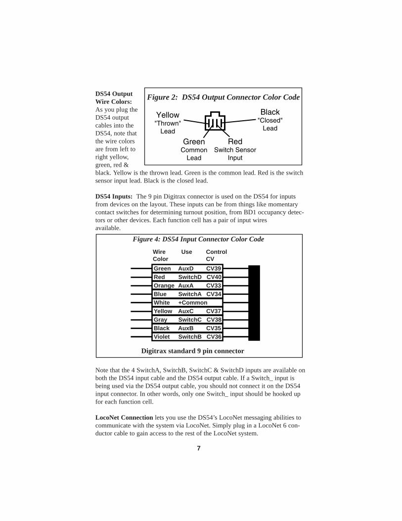
DS54 OutputWire Colors: As you plug theDS54 outputcables into theDS54, note thatthe wire colorsare from left toright yellow,green, red &black. Yellow is the thrown lead. Green is the common lead. Red is the switchsensor input lead. Black is the closed lead.
DS54 Inputs: The 9 pin Digitrax connector is used on the DS54 for inputsfrom devices on the layout. These inputs can be from things like momentarycontact switches for determining turnout position, from BD1 occupancy detec-tors or other devices. Each function cell has a pair of input wiresavailable.
Note that the 4 SwitchA, SwitchB, SwitchC & SwitchD inputs are available onboth the DS54 input cable and the DS54 output cable. If a Switch_ input isbeing used via the DS54 output cable, you should not connect it on the DS54input connector. In other words, only one Switch_ input should be hooked upfor each function cell.
LocoNet Connection lets you use the DS54’s LocoNet messaging abilities tocommunicate with the system via LocoNet. Simply plug in a LocoNet 6 con-ductor cable to gain access to the rest of the LocoNet system.
Violet � SwitchB CV36
Green � AuxD � CV39Red � SwitchD CV40Orange� AuxA � CV33Blue � SwitchA CV34White � +CommonYellow � AuxC � CV37Gray � SwitchC CV38Black � AuxB � CV35
WireColor
Use ControlCV
Figure 4: DS54 Input Connector Color Code
Digitrax standard 9 pin connector
GreenCommon
Lead
Black"Closed"
Lead
Yellow"Thrown"
Lead
RedSwitch Sensor
Input
Figure 2: DS54 Output Connector Color Code
7

CV Program Enable Link is used to program the DS54. It must be in theopen position with one pin uncovered for regular operation. To program theDS54, move the link so that it is closed with both pins covered to enable pro-gramming. Be sure to put the Programming Enable Link back in the open posi-tion when programming is completed.
Address Program Button is used to program the DS54’s stationary addressand 4 associated switch addresses.
Local Ground: the screw terminal next to the LocoNet connector is the localDS54 ground for connecting devices to the the DS54. If using the DS54 onlyfor switch control, LocoNet and system ground are not required. Connectingthe DS54 to the booster via LocoNet for feedback messaging will provide anynecessary system ground. DO NOT connect this to a house ground (water pipe,electrical ground connection, etc) or it may result in damage to the DS54.
Auxiliary Power 12-16V AC/DC connections: red (+) & black (-) wires areused to connect an auxiliary 12-16 volt AC/DC power source. Digitrax recom-mends use of auxiliary power for all turnout machine types to achieve optimaloperation. Digitrax PS12 Power Supply is excellent for this purpose.
#6-32 Screw Terminals are for connecting the DS54 to the local section ofDCC powered track. The DS54 normally gets its power via these terminals.
5.0 Installing A DS54 Under The Layout
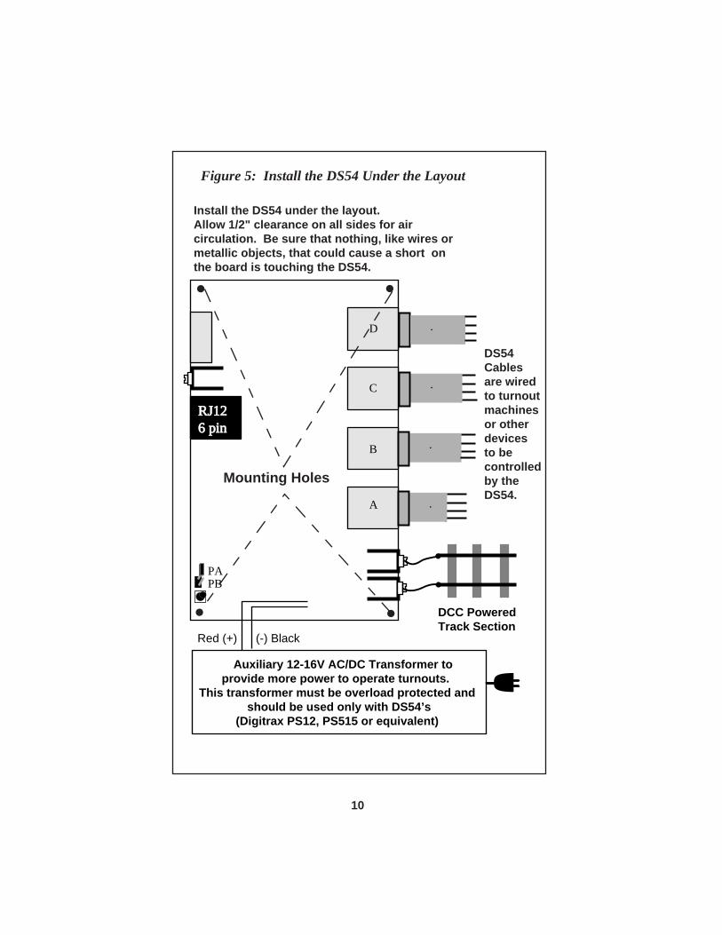
Refer to Figure 5: Install the DS54 Under the Layout. To Install the DS54 under the layout:
1. DS54s can be programmed either before or after they are installed onthe layout. If you are installing your first DS54 and will use switchaddresses 01, 02, 03 & 04 only for operating solenoid type turnoutmachines you can proceed with the installation. a) For slow motion turnout machines see Section 6.1.2. b) To change the switch addresses or other CVs see theProgramming Section below before proceeding with the installa-tion.c) To set up feedback or other intermediate and advance fea-tures, see Sections 13 & 14 and program the DS54 before pro-ceeding with the installation
2. Mount the DS54 under the layout using the four mounting holes inthe corners of the unit.
3. Allow a minimum of 1/2" spacing all around for air circulation. 4. Be sure that no metallic objects or wires are touching the board that
could create a short circuit.
8
5. The DS54 board can be physically located anywhere that is conve-nient to the turnouts under its control.
6. To connect to LocoNet, simply run a LocoNet cable from the closestLocoNet device that is already hooked up and plug it in to theLocoNet port on the DS54. Remember to test the LocoNet cableswith the LT1 tester that came with your starter set. If you are notusing the feedback features built in to the DS54 you do not need toconnect to the RJ12 LocoNet Connection.
7. Power the DS54 by connecting the #6-32 screw terminals to a localsection of DCC powered track. Connect one wire to each DCC pow-ered rail (polarity does not matter). 20 to 22AWG wire is recom-mended for this connection.
5.1 Auxiliary PowerTo provide enough power to the DS54 to avoid power drops on the systemwhen multiple turnout machines are operated simultaneously or if you wantslow motion turnouts to operate faster, provide additional power to the DS54.
Digitrax recommends using auxiliary power for all turnout machine types.
This auxiliary power can be from any transformer with a voltage between 12V & 16V AC/DC. The transformer should be overload protected and only beused with DS54s. Digitrax PS12 12V AC Adapter is excellent for providingauxiliary power for DS54s. The red auxiliary power input is positive (+) andthe black is negative (-). See Figures 3 & 5.
When using more than one DS54, make sure that the polarity is the samefor all auxiliary power inputs.
9
A
B
C
D
RJ126 pin
PAPB
Auxiliary 12-16V AC/DC Transformer toprovide more power to operate turnouts.
This transformer must be overload protected and should be used only with DS54’s
(Digitrax PS12, PS515 or equivalent)
DCC Powered Track Section
Mounting Holes
DS54 Cablesare wiredto turnoutmachines or otherdevicesto becontrolledby theDS54.
Install the DS54 under the layout.Allow 1/2" clearance on all sides for aircirculation. Be sure that nothing, like wires ormetallic objects, that could cause a short on the board is touching the DS54.
Red (+) (-) Black
Figure 5: Install the DS54 Under the Layout
10

11
GreenCommonLead
Black"Closed"Lead
Switch #1
Solenoid Turnout MachineNon ReportingHook-Up Example
Yellow"Thrown"Lead
Each individual output can be hooked up as a reporting or
non-reporting switch, as a solenoid or slow motion turnout machine or
as another type of accessory.
GreenCommonLead
Black "Closed" Lead
Yellow"Thrown"Lead
RedSwitchSensorInputLeadReporting
Hook-Up Example
If you are not using reporting, simply leave the red switch sensorinput lead unconnected.
To use turnout reporting, connect switches as shown so contactsare closed when the turnout is closed, & connect the DS54 toLocoNet with a LocoNet 6 conductor cable via the 6 pin RJ12 connector on the DS54.
DS5
4 C
able
s fr
om D
S54
RedLead
Not Used
Solenoid Turnout Machine
Figure 6: Hooking up solenoid turnout machines.Non-reporting and reporting examples

6.0 Using the DS54’s Outputs
Each of the DS54’s outputs can be set up to run solenoid (snap) turnoutmachines, slow motion (Tortoise type) turnout machines, bi-polar turnoutmachines, DC motors and lamps on the layout. More than one type of outputmay be combined on each DS54 to control different types of turnout machines,DC motors and/or lamps, all controlled by one DS54!
6.1 Turnout Machines
Most DS54s are used to control turnout machines on the layouts. The following Sections illustrate how to hook up each kind of turnout machine.
6.1.1 Solenoid Turnout Machines
A solenoid turnout machine is operated by a pulse of current that operates theturnout. Atlas and Peco snap switches are examples of this type of turnoutmachine. The DS54 comes from the factory programmed for operatingsolenoid turnout machines. When using only solenoid turnouts, simply hook upthe DS54 according to Figure 6.
As it comes from the factory, the DS54 is set up for pulse retriggerable opera-tion with a duration of about .125 seconds. This means that each time a turnoutis activated, the DS54 sends a pulse of current to the appropriate solenoid forabout 1/8th of a second. Retriggerable means that if another command is sentto the DS54 before the first action is completed, the DS54 will ignore the firstcommand and execute the new one immediately.
CAUTION: Controlling more than one solenoid turnout with a single DS54 output is not recommended.
To hook up solenoid turnout machines:
1. Disconnect or turn off DCC track power and any auxiliary power sup-plies installed on the layout.
2. Install the DS54 under the layout and provide power for it asdescribed in Section 5.0.
3. The DS54 is programmed at the factory to stationary decoder address01 so that the Outputs A, B, C, & D correspond to switch addressnumbers 01, 02, 03, and 04 respectively.
4. Connect each turnout machine to the DS54 using the four-pin cablesprovided.
5. Connect the black wire to the closed lead on the turnout machine6. Connect the green wire to the "common" lead on the turnout machine
12

13
ABCD
RJ1
26
pin
CV
Prog
ram
En
able
Lin
k(in
stal
l jum
per l
ink
betw
een
PA &
PB
durin
g pr
ogra
mm
ing)
#6-3
2 Sc
rew
Te
rmin
als
PA PBIs
olat
ed P
rogr
amm
ing
Trac
kPA PBPA PB
Yello
w"T
hrow
n"Le
ad
Atta
ch to
eith
erra
il of
Pro
gram
min
gTr
ack
with
a c
lip le
ad10
0 oh
m2
wat
tR
esis
tor
Ope
nN
orm
alO
pera
tion
Clo
sed
For
CV
Prog
ram
min
g
Prog
ram
Fee
dbac
k A
dapt
er (N
eede
d fo
rpr
ogra
mm
ing
and
read
ing
back
CVs
)
Figure 7 : Programming DS54 CVs and Reading back CVs

7. Connect the yellow wire to the thrown lead on the turnout machine8. Connect the heavy red and black auxiliary power wires to the dedicat-
ed DS54 auxiliary power supply (Digitrax PS12 or equivalent).9. (Optional) Connect the red wire in the DS54 output cable as shown to
a switch sensor input for standard turnout position reporting. Exactturnout position reporting is discussed in detail in Section 10.
10. Turn on the DCC track power and auxiliary DS54 power supply. 11. Issue a SWITCH command to switch address 01 from a throttle. (To
do this, put the throttle in SWITCH mode, select switch address 01and press the c or t button on the throttle to operate the turnout.)OutputA of the DS54 will send a pulse to the turnout machine con-nected to it each time the turnout is commanded to change fromclosed to thrown & vice-versa.
12. Send commands to switch address 02 and OutputB will operate theturnout connected to it. Continue with switch address 03 & 04 tocheck Outputs C & D.
6.1.2 Slow Motion Turnout Machines
A slow motion turnout machine uses a steady stream of current to move theturnout. Examples of slow motion turnout machines are Tortoise (made byCircuitron) and SwitchMaster. Since the DS54 comes from the factory set foroperation of solenoid turnout machines, CVs 03, 04, 05, & 06 will have to bereprogrammed to set up the DS54 for slow motion operation of one or moreoutputs. CV programming will be covered in more detail shortly.
How to set up a DS54 for Slow Motion Turnout Operation:
1. Move the CV Program Enable Link so that both pins PA & PB arecovered to enable programming.
2. Connect the DS54 to the programming track as shown in Figure 7.You can use the 100ohm 2 watt resistor that came with your starterset test kit to protect the DS54 from being damaged if track power isapplied accidentally during programming.
3. Put the system into programming mode. 4. Program CV03 to the value of x20/032 (20 hex or 32 decimal). 5. Repeat step 4 to program CV04 to x20/032, CV05 to x20/032 &
CV06 to x20/032 to set up all four outputs on the DS54 for operat-ing slow motion turnout machines.
14

The chart below shows you which CV and which CV value to programfor each of the DS54’s outputs and their corresponding values.
6. When you are finished entering values for each of the DS54’sOutputs, exit programming mode.
7. Move the CV Program Enable Link so that only one pin is covered todisable programming mode on the DS54.
8. Proceed with connecting the DS54 to slow motion turnout machineson the layout as shown in Figure 8.
Black Closed Lead
Yellow Thrown Lead
Green Common Lead
1
8
Slow-MotionTurnoutMotor
To DS54
Red Switch Sensor Input Lead
Figure 8: Hook up for Slow Motion Turnout Machine
CV# Usage Solenoid Slow Motion CV03 OutputA x00/000 x20/032 CV04 OutputB x00/000 x20/032 CV05 OutputC x00/000 x20/032 CV06 OutputD x00/000 x20/032
15
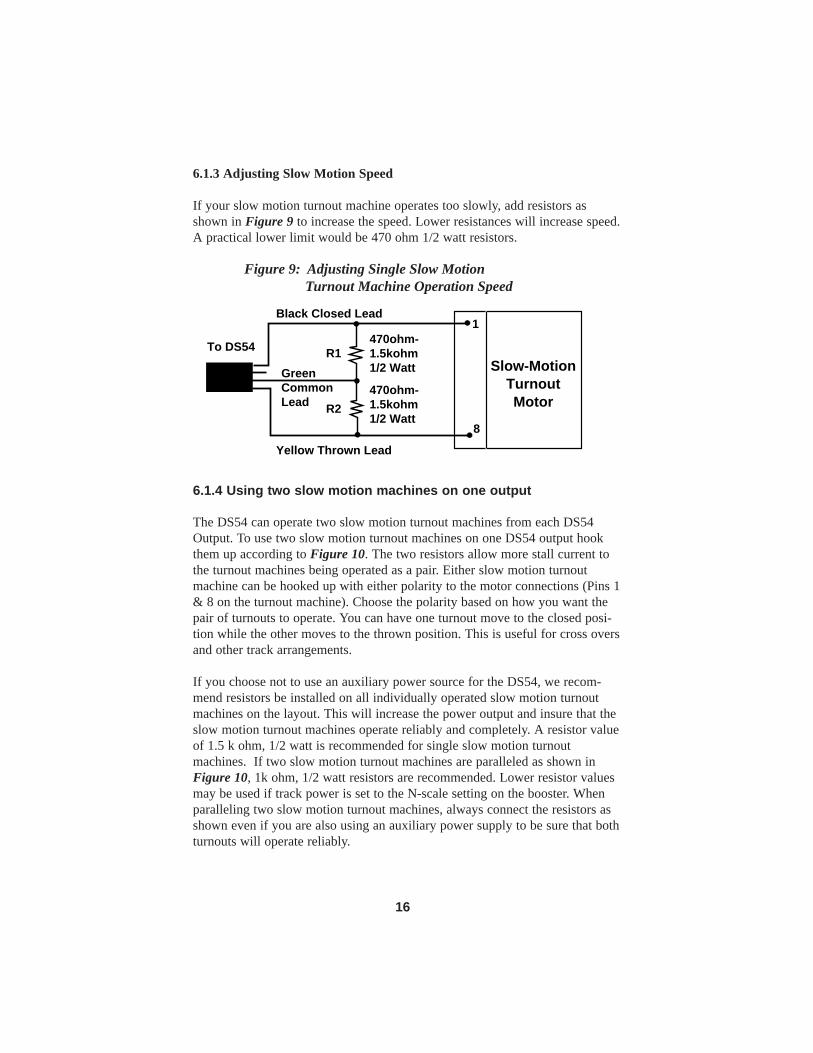
6.1.3 Adjusting Slow Motion Speed
If your slow motion turnout machine operates too slowly, add resistors asshown in Figure 9 to increase the speed. Lower resistances will increase speed.A practical lower limit would be 470 ohm 1/2 watt resistors.
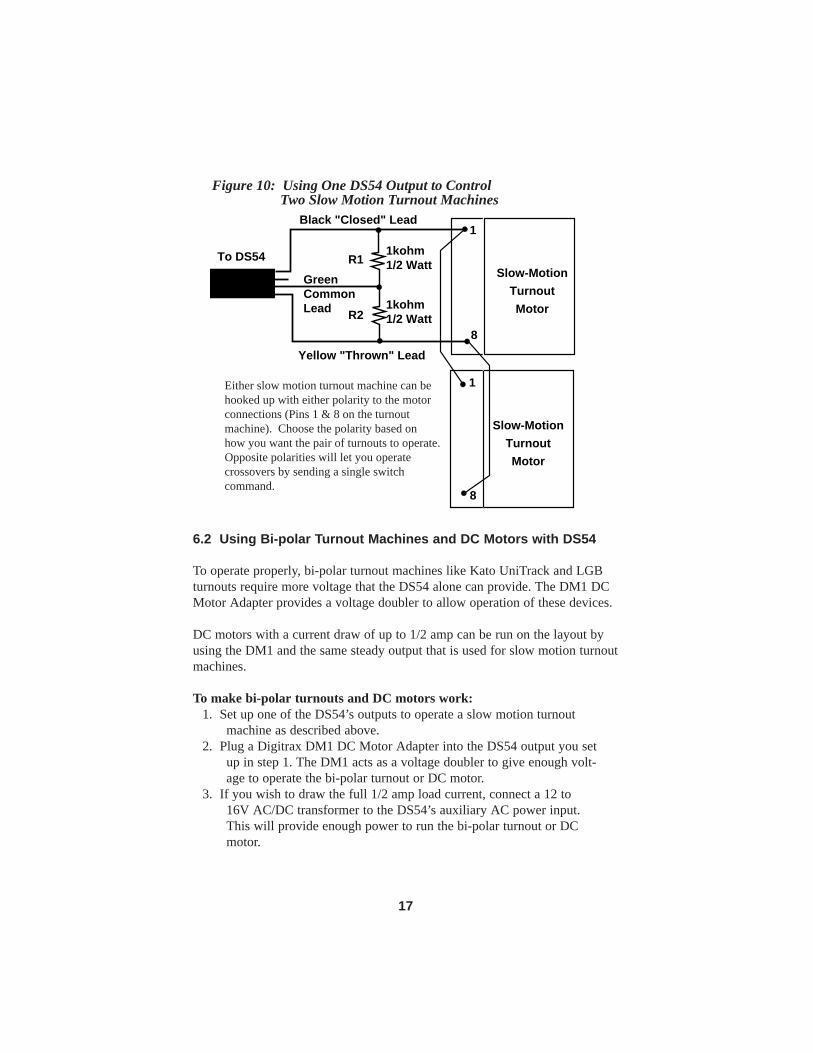
6.1.4 Using two slow motion machines on one output
The DS54 can operate two slow motion turnout machines from each DS54Output. To use two slow motion turnout machines on one DS54 output hookthem up according to Figure 10. The two resistors allow more stall current tothe turnout machines being operated as a pair. Either slow motion turnoutmachine can be hooked up with either polarity to the motor connections (Pins 1& 8 on the turnout machine). Choose the polarity based on how you want thepair of turnouts to operate. You can have one turnout move to the closed posi-tion while the other moves to the thrown position. This is useful for cross oversand other track arrangements.
If you choose not to use an auxiliary power source for the DS54, we recom-mend resistors be installed on all individually operated slow motion turnoutmachines on the layout. This will increase the power output and insure that theslow motion turnout machines operate reliably and completely. A resistor valueof 1.5 k ohm, 1/2 watt is recommended for single slow motion turnoutmachines. If two slow motion turnout machines are paralleled as shown inFigure 10, 1k ohm, 1/2 watt resistors are recommended. Lower resistor valuesmay be used if track power is set to the N-scale setting on the booster. Whenparalleling two slow motion turnout machines, always connect the resistors asshown even if you are also using an auxiliary power supply to be sure that bothturnouts will operate reliably.
Black Closed Lead
Yellow Thrown Lead
GreenCommonLead
1
8
Slow-MotionTurnoutMotor
470ohm-1.5kohm1/2 Watt
R1
R2
To DS54
470ohm-1.5kohm1/2 Watt
Figure 9: Adjusting Single Slow Motion Turnout Machine Operation Speed
16
6.2 Using Bi-polar Turnout Machines and DC Motors with DS54
To operate properly, bi-polar turnout machines like Kato UniTrack and LGBturnouts require more voltage that the DS54 alone can provide. The DM1 DCMotor Adapter provides a voltage doubler to allow operation of these devices.
DC motors with a current draw of up to 1/2 amp can be run on the layout byusing the DM1 and the same steady output that is used for slow motion turnoutmachines.
To make bi-polar turnouts and DC motors work:1. Set up one of the DS54’s outputs to operate a slow motion turnout
machine as described above.2. Plug a Digitrax DM1 DC Motor Adapter into the DS54 output you set
up in step 1. The DM1 acts as a voltage doubler to give enough volt-age to operate the bi-polar turnout or DC motor.
3. If you wish to draw the full 1/2 amp load current, connect a 12 to16V AC/DC transformer to the DS54’s auxiliary AC power input.This will provide enough power to run the bi-polar turnout or DCmotor.
Black "Closed" Lead
Yellow "Thrown" Lead
GreenCommonLead
1
8
Slow-MotionTurnoutMotor
1kohm1/2 WattR1
R21kohm1/2 Watt
1
8
Slow-MotionTurnoutMotor
To DS54
Figure 10: Using One DS54 Output to Control Two Slow Motion Turnout Machines
Either slow motion turnout machine can behooked up with either polarity to the motorconnections (Pins 1 & 8 on the turnoutmachine). Choose the polarity based onhow you want the pair of turnouts to operate.Opposite polarities will let you operatecrossovers by sending a single switchcommand.
17

6.3 Controlling Stationary Lamps with the DS54
The DS54’s outputs can control lamps on the layout, too. Each lamp can be setup to be on steady when activated by the throttle or they can be set to blink at arange of rates. For lamp control, program the output type CV for the functioncell you are using to a value of x20/032 to x27/039. See Table II for the blink-ing effect caused by each different CV value.
For operating lamps a closed command (“c”) turns the lamp ON and a throwncommand (“t”) turns the lamp OFF.
7.0 Issuing SWITCH Commands With A Digitrax Throttle
Digitrax produces many different throttles that can be used with LocoNet sys-tems. The following instructions will help you learn to operate your DS54swith most Digitrax throttles. If the throttle you are using is not detailed here,please consult your Starter Set Manual or Throttle Manual for completeinstructions.
7.1 DT400 Series Throttle
To change the position of a switch or turnout
1. Press the SWCH key to enter switch mode. When you enterSwitch mode, the throttle knobs & direction keys will continue tocontrol the loco addresses running on the throttle. Loco speed willbe displayed on the bar graph and loco direction will be displayedon the direction indicators for each throttle. The numeric keypad will
be used to enter switch numbers and the OPTN t and CLOC c
Keys are used to tell the switch or turnout in which direction itshould operate.
2. The last switch decoder address selected by the throttle is displayedon the text line followed by a “c” or a “t”.
3. The LCD indicates the switch position using the c or t as follows:“t” indicates that the switch is “thrown” (for a turnout, the diverging
route is set)“c” indicates that the switch is “closed” (for a turnout, the mainline
route is set) If the “t” or “c” indicator is flashing it means that the LocoNet
Command Station does not know the current switch position. Asteady “t” or “c” indicates that the command station knows the posi-tion of the switch.
C L O C
c
O P T N
t
S W C HS W C H
18

4. Use the numeric keypad to enter the switch address you want tochange
5. Once the desired switch address appears in the text area of the throt-tle, you will see either “c” or “t” on the right side of the = sign in thedisplay. If the “c” or “t” is flashing, the command station does not
know the position for this turnout. Press the OPTN t Key to
move the switch to the “thrown” position OR the CLOC c Key to move it to the “closed” position.
6. If the switch selected is a turnout connected to an accessory decoder,it will change position from closed to thrown or vice-versa. If theswitch selected is an op switch setting for the command station, thesoftware switch inside the command station will be changed.
7. After commanding the switch “closed” or “thrown” the switch posi-tion display will stop flashing, since the command station nowknows the current switch position.
Note that the accessory decoders in the system are accessible to all throttles orcontrol devices with switch control capabilities & are not reserved in-use to asingle throttle like locomotive decoders.
8. When you have finished Sw (switch) operations, return to Fn (Normal
Operating Mode) by pressing the EXIT Key or the FUNC Key
9. The next time you enter Sw mode , the DT400 will remember whereyou left off & start at the last switch address & position you used.
F U N C
E X I T
C L O CC L O C
cc
O P T NO P T N
tt
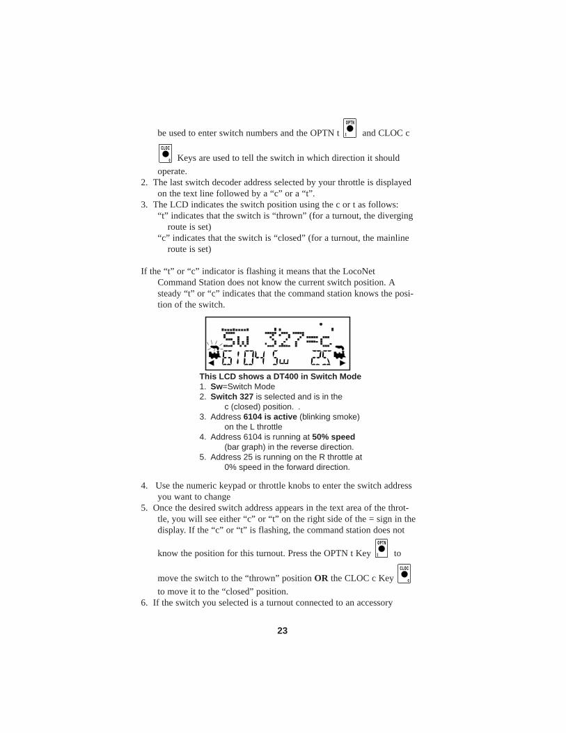
This LCD shows a DT400 in Switch Mode1. Sw=Switch Mode2. Switch 327 is selected and is in the
c (closed) position. .3. Address 6104 is active (blinking smoke)
on the L throttle4. Address 6104 is running at 50% speed
(bar graph) in the reverse direction.5. Address 25 is running on the R throttle at
0% speed in the forward direction.
19

20
7.2 DT300 Series ThrottleTo change the position of a turnout using a DT300 Series Throttle:
1. Press the MODE Key until the mode indicator in the center ofthe bottom line of the DT300’s LCD shows Sw.
2. The last switch decoder address selected on the throttle is displayedon the text line followed by a “c” or a “t”.
3. The LCD indicates the switch position using the c or t as follows:“t” indicates that the switch is “thrown” (for a turnout, the diverging
route is set)“c” indicates that the switch is “closed” (for a turnout, the mainline
route is set)
If the “t” or “c” indicator is flashing it means that the LocoNetCommand Station does not know the current switch position.
This display example shows Switch Address Number 327 is in the closedposition.
4. Dial up the switch address you want to change by using either throt-
tle knob or the Y + and N - Keys. You can also use the Lthrottle knob to set the 100s and the R throttle knob to set the 1s.
5. Once the desired switch address appears in the test area of the throt-tle, you will see either “c” or “t” on the right side of the = sign in thedisplay. If the “c” or “t” is flashing, the command station does notknow the position for this turnout. Press either the L Reverse Key
to move the switch to the “thrown” position or the R Reverse
Key to move it to the “closed” position.6. If the switch you selected is a turnout connected to an accessory
decoder, it will change position from closed to thrown or vice-versa.If the switch selected in an op switch setting for the DB150 com-mand station, the software switch will be changed.
7. After commanding the switch “closed” or “thrown” the switch posi-tion display will stop flashing, since the command station nowknows the current switch position.
Note that the accessory decoders in the system are accessible to all throttles or
Rc
L t
NY +
This LCD shows a DT400 in Switch Mod
M O D E

control devices with switch control capabilities & are not reserved in-use to asingle throttle like locomotive decoders.
When Sw (switch) operations are complete, return to Lo (Loco) mode by:
1. Pressing the MODE Key twice (skipping past MU mode), 2. Pressing down on either throttle knob or3. Wait for the 6 second no-input inactivity time-out to return the DT300
to the Lo (Loco) default mode. The next time you enter Sw mode , the DT300 will remember where you leftoff & start at the last switch address & position you accessed.
7.3 UT Series ThrottleTo change the position of a turnout using a UT Series Throttle:
1. Press the "RUN/STOP" and the "OpSw" buttons at the same time toactivate "SWITCH" Mode.
2. Use the two rotary selectors on the UT2 to select the turnout addressto throw or close (With the UT2 you are limited to a two digitturnout address).
3. The "c" LED will light if the last known state of the turnout selectedis the "closed" position.
4. Press "ACQ" to throw or close the turnout.5. The "c" LED will be dark if the last known state of the turnout select-
ed is the "thrown" position.6. If the "c" LED flashes on and off, the turnout state is unknown.7. Return the rotary selector switches to the locomotive address before
exiting "Switch Mode". If the locomotive address is not correct thelocomotive will be released.
8. Press "RUN/STOP" and "OPSW" at the same time to return to normaloperation.
While in "Switch" Mode, you can still control the speed and direction of yourlocomotive. Functions will also operate normally while in SWITCH Mode.
7.4 DT100 & DT200 Series Throttles
To change the position of a turnout using a D100 or DT200 SeriesThrottle:
1. Press the MODE/DISP key until the SWITCH mode indicator is litin the LCD.
2. The display shows the switch address in the left hand side of the dis-play and the turnout position in the left hand side of the display. Youwill see a two digit switch address followed by a -t or -c for thrown
M O D E
21
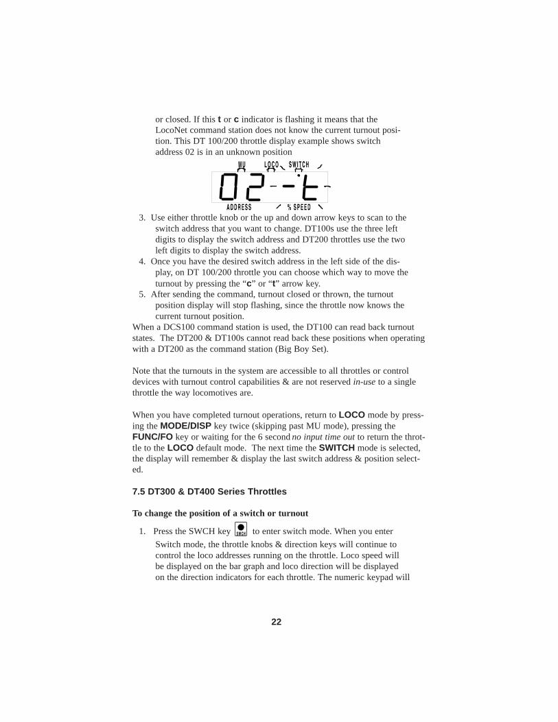
or closed. If this t or c indicator is flashing it means that theLocoNet command station does not know the current turnout posi-tion. This DT 100/200 throttle display example shows switchaddress 02 is in an unknown position
3. Use either throttle knob or the up and down arrow keys to scan to theswitch address that you want to change. DT100s use the three leftdigits to display the switch address and DT200 throttles use the twoleft digits to display the switch address.
4. Once you have the desired switch address in the left side of the dis-play, on DT 100/200 throttle you can choose which way to move theturnout by pressing the “c” or “t” arrow key.
5. After sending the command, turnout closed or thrown, the turnoutposition display will stop flashing, since the throttle now knows thecurrent turnout position.
When a DCS100 command station is used, the DT100 can read back turnoutstates. The DT200 & DT100s cannot read back these positions when operatingwith a DT200 as the command station (Big Boy Set).
Note that the turnouts in the system are accessible to all throttles or controldevices with turnout control capabilities & are not reserved in-use to a singlethrottle the way locomotives are.
When you have completed turnout operations, return to LOCO mode by press-ing the MODE/DISP key twice (skipping past MU mode), pressing theFUNC/FO key or waiting for the 6 second no input time out to return the throt-tle to the LOCO default mode. The next time the SWITCH mode is selected,the display will remember & display the last switch address & position select-ed.
7.5 DT300 & DT400 Series Throttles
To change the position of a switch or turnout
1. Press the SWCH key to enter switch mode. When you enterSwitch mode, the throttle knobs & direction keys will continue tocontrol the loco addresses running on the throttle. Loco speed willbe displayed on the bar graph and loco direction will be displayedon the direction indicators for each throttle. The numeric keypad will
S W C H
22
be used to enter switch numbers and the OPTN t and CLOC c
Keys are used to tell the switch in which direction it shouldoperate.
2. The last switch decoder address selected by your throttle is displayedon the text line followed by a “c” or a “t”.
3. The LCD indicates the switch position using the c or t as follows:“t” indicates that the switch is “thrown” (for a turnout, the diverging
route is set)“c” indicates that the switch is “closed” (for a turnout, the mainline
route is set)
If the “t” or “c” indicator is flashing it means that the LocoNetCommand Station does not know the current switch position. Asteady “t” or “c” indicates that the command station knows the posi-tion of the switch.
4. Use the numeric keypad or throttle knobs to enter the switch addressyou want to change
5. Once the desired switch address appears in the text area of the throt-tle, you will see either “c” or “t” on the right side of the = sign in thedisplay. If the “c” or “t” is flashing, the command station does not
know the position for this turnout. Press the OPTN t Key to
move the switch to the “thrown” position OR the CLOC c Key to move it to the “closed” position.
6. If the switch you selected is a turnout connected to an accessory
C L O C
c
O P T N
t
This LCD shows a DT400 in Switch Mode1. Sw=Switch Mode2. Switch 327 is selected and is in the
c (closed) position. .3. Address 6104 is active (blinking smoke)
on the L throttle4. Address 6104 is running at 50% speed
(bar graph) in the reverse direction.5. Address 25 is running on the R throttle at
0% speed in the forward direction.
C L O C
c
O P T N
t
23
decoder, it will change position from closed to thrown or vice-versa.If the switch you selected is an op switch setting for your commandstation, the software switch inside the command station will bechanged.
7. After commanding the switch “closed” or “thrown” the switch posi-tion display will stop flashing, since the command station nowknows the current switch position.
Note that the accessory decoders in the system are accessible to all throttles orcontrol devices with switch control capabilities & are not reserved in-use to asingle throttle like locomotive decoders.
8. When you have finished your Sw (switch) operations you can return
to Fn (Normal Operating Mode) by pressing the EXIT Key or
the FUNC Key .
9. The next time you enter Sw mode , the throttle will remember whereyou left off & start at the last switch address & position youaccessed.
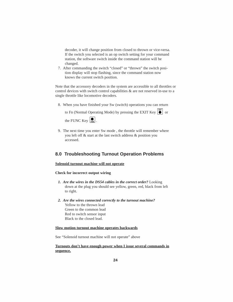
8.0 Troubleshooting Turnout Operation Problems
Solenoid turnout machine will not operate
Check for incorrect output wiring
1. Are the wires in the DS54 cables in the correct order? Lookingdown at the plug you should see yellow, green, red, black from leftto right.
2. Are the wires connected correctly to the turnout machine?Yellow to the thrown lead Green to the common leadRed to switch sensor input Black to the closed lead.
Slow motion turnout machine operates backwards
See “Solenoid turnout machine will not operate” above
Turnouts don’t have enough power when I issue several commands insequence.
F U N C
E X I T
24

Add auxiliary AC for better turnout response. This auxiliary AC/DC can befrom any transformer with a voltage between 12V & 16V AC/DC. This trans-former should be overload protected & only be used with DS54s & not sharedwith boosters in the system. If you are only sending commands to one solenoidat a time, wait for about 1/2 second between commands and you probablywon’t need to use the auxiliary AC/DC input. Digitrax PS12 & PS515 are greatfor this purpose.
Balky solenoid turnouts
If the turnout is balky & does not operate reliably, check for mechanical fric-tion or jamming problems. These mechanical problems must be remedied, forproper operation. If you are still having problems after correcting mechanicalissues, a higher voltage might help the solenoid turnout work more reliably.See above info on adding auxiliary AC/DC input.
Turnout position does not correspond to command issued
If the system shows the turnout should be thrown, but the solenoid actuallycloses the turnout, reverse the wiring for the solenoid turnout machine. Simplydisconnect the plug output lead from the DS54, & reverse the solenoid connec-tions to the black & yellow (outer 2 wires in the flat cable) leads that activatethe solenoid. Plug in again & recheck that the turnout position matches thatreported by the system.
9.0 DS54 AddressesEach DS54 can be programmed to access 4 of the 2044 switch addresses acces-sible with the DS54. Each DS54 has a stationary decoder address (there are 511stationary decoder addresses). Each stationary decoder address has four consec-utive switch addresses associated with the DS54’s four outputs. This meansthat DS54 switch addresses come in groups of 4.
511 Stationary decoder addresses x 4 Switch addresses Equals 2044 switch addresses.
For each DS54, OutputA corresponds to the first switch address in an station-ary decoder address group. For example, if you program the DS54 to stationarydecoder address 02, it will respond to the group of switch addresses 05, 06, 07,& 08, OutputA will be switch address 05, OutputB will be 06, OutputC will be07, & OutputD will be 08.
Note: The Stationary Decoder Address is actually programmed into CV513.
25

Since this CV is not accessible by all DCC systems, the DS54 is set up so thatlower CVs, starting with CV01 can be used for programming. If you are usinga system that does access high CVs, simply add 512 to the CV numbers yousee in this manual.
Address Set Up for DS54 BEFORE Installation on Layout:1. If you are using this method of programming, be sure that the DS54 is
not connected to the rest of your layout. It should only be connectedto the programming output of the DCS100 or DCS50. If using aDB150, be sure the DS54 is isolated from the rest of the layout.
2. Start with the command station in PROGRAM mode.3. Move the DS54’s CV Program Enable Link so that both pins PA &
PB are covered to enable programming.4. Connect the yellow wire of one of the outputs through a 100ohm
resistor to one of the rail terminals on the DS54. See Figure 7.5. Press the address program button on the DS54 you to set up and hold
for about 2 seconds.6. Go into PROGRAM Mode with your throttle. Select PAGED PRO-
GRAMMING. Send a SWITCH command from the throttle usingany address in the range of 4 addresses you want to set up for theDS54. The address of the SWITCH command sent will automatical-ly be programmed into your DS54.
7. When you are finished, exit programming mode on your throttle andopen the DS54’s programming link.
Switch address groups do not have to be used in order. So, if you have just 2DS54s on your layout, you could program them as follows: DS54 stationarydecoder address 07 with switch addresses 25, 26, 27, 28 and DS54 stationarydecoder address 15 with switch addresses 53, 54, 55, 56 on the layout.
These examples will get you started:DS54 outputs & corresponding switch addresses DS54’s 4 function cells respond to DCC commands for these switch addresses DS54 Stationary Decoder Address
Switch Address- Function Cell A
Switch Address- Function Cell B
Switch Address- Function Cell C
Switch Address- Function Cell D
01 01 02 03 04 02 05 06 07 08 03 09 10 11 12 04 13 14 15 16 05 17 18 19 20
26

9.1 Changing the Address of a DS54 Installed on the LayoutThis procedure lets you change the DS54’s stationary decoder addresses andassociated group of four switch addresses only. For information about program-ming other CVs see Section 12 below. This procedure can be used for decodersinstalled on the layout. Using this procedure, you can change addresses withouthaving to remove the decoder from the layout.
For Switch Addresses 01-252:1. Turn on DCC track power.2. Press & hold the Address Program Button on the DS54 for 1 second
then release it. This will cause the DS54 to accept the next SWITCHcommand sent from the command station and re-program theDS54’s stationary decoder address and its four related switchaddresses.
3. Use a throttle to send a SWITCH command to any switch address inthe group of four switch addresses that you want to program theDS54 to respond to. You can send either a c or t command.
4. Once the SWITCH command is received, the DS54 decoder returnsto normal operating mode.
For Switch Addresses 253 & above:After completing steps 1-4 above,
5. Turn track power off for about 10 seconds, then turn track power backon to complete updating the programming in the DS54. Do this stepif you are changing the address of a decoder either to or from anaddress higher than 252.
10.0 Using DS54 Inputs
The DS54 has 8 inputs that can be used for turnout position reporting, layoutautomation, occupancy detection, etc. Figure 11 shows how the wires on theDigitrax Standard 9 pin wire harness are used as DS54 inputs. Notice that eachfunction cell A, B, C, & D has two input wires. The 2 input wires for functioncell A are called SwitchA input and AuxA input. The 2 input wires for functioncell B are called SwitchB input and AuxB input and so on. The white wire onthe connector provides the +Common power connection.
27
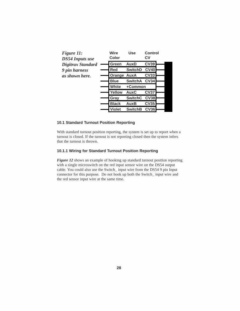
10.1 Standard Turnout Position Reporting
With standard turnout position reporting, the system is set up to report when aturnout is closed. If the turnout is not reporting closed then the system infersthat the turnout is thrown.
10.1.1 Wiring for Standard Turnout Position Reporting
Figure 12 shows an example of hooking up standard turnout position reportingwith a single microswitch on the red input sensor wire on the DS54 outputcable. You could also use the Switch_ input wire from the DS54 9 pin Inputconnector for this purpose. Do not hook up both the Switch_ input wire andthe red sensor input wire at the same time.
Violet � SwitchB CV36
Green � AuxD � CV39Red � SwitchD CV40Orange� AuxA � CV33Blue � SwitchA CV34White � +CommonYellow � AuxC � CV37Gray � SwitchC CV38Black � AuxB � CV35
WireColor
Use ControlCV
Figure 11: DS54 Inputs useDigitrax Standard 9 pin harness as shown here.
28

Link
age
ALi
nkag
e B
Con
nect
to s
low
mot
ion
actu
ator
or h
and
thro
w le
ver.
PAPB
XAXB
"Dire
ct P
oint
Sens
e In
put"
See
Text
C1
D1
IN40
01or
sim
ilar
devi
ce10
uf, 2
5Vor
sim
ilar
devi
ce
MS2
MS1
Com
Nor
mal
lyO
pen
Nor
mal
lyO
pen
Com
+CO
M
Switc
hDin
put
Aux
Din
put
Stan
dard
Tur
nout
Pos
ition
Fee
dbac
k:
Adju
st L
inka
ge A
so
that
mic
rosw
itch
MS1
is
act
ivat
ed w
hen
the
turn
out i
s cl
osed
for
stan
dard
feed
back
. St
anda
rd fe
edba
ckte
lls y
ou w
heth
er th
e tu
rnou
t is
clos
ed.
Exac
t Tur
nout
Pos
ition
Fee
dbac
k:
Adju
st L
inka
ge B
so
that
mic
rosw
itch
MS2
is
act
ivat
ed w
hen
the
turn
out i
s th
row
n.
Addi
ng th
e se
cond
mic
rosw
itch
give
s yo
uex
act f
eedb
ack
as to
whe
ther
the
turn
out i
scl
osed
, thr
own
or in
tran
sit.
Bla
ck, D
S54
Com
mon
Figure 12: Turnout position reporting with DS54
29

10.1.2 Program DS54 for Standard Turnout Position Reporting
To set up standard turnout position reporting, program the Switch_ input typeCV and the Switch_ message type CV.
10.2 Exact Turnout Position Reporting
Exact turnout position reporting uses LocoNet messages that tell the systemwhether the turnout is thrown, closed, or unsafe/in transit. When using exactturnout position reporting, the system reports that the turnout is unsafe/in tran-sit during the interval between closed and thrown messages.
10.2.1 Wiring for Exact Turnout Position Reporting
Figure 12 shows how to set up a turnout for exact turnout position reporting.In this diagram two microswitches, MS1 and MS2, are used to determine theposition of the turnout that is reported to the system. The microswitches areconnected to the throw bar of the turnout or to the actuator of the turnoutmachine. When the turnout is closed, MS1 is in contact with the actuator andthe message that the turnout is actually closed is sent to the system. This mes-sage can be used to display the turnout position in handheld throttles, on com-puter throttles or even on LEDs mounted on a layout fascia panel. When theturnout is operated, the second microswitch, MS2, makes contact and anothermessage is sent indicating that the turnout is in the thrown position. While theturnout is in transit, the system will report that the turnout position is notknown (and therefor unsafe/in transit)..
When hooking up a DS54 for exact turnout position reporting, follow the con-vention of using the Switch_ input wire for reporting closed and the Aux_input wire to report thrown. The message for closed and thrown is sent whenthe input is activated.
10.2.2 Programming the DS54 for Exact Turnout Position Reporting
To implement exact turnout position reporting, program the Aux_ input mes-sage type for exact feedback. The default for the Aux_ input line tells the sys-tem that it is not being used for exact feedback reporting. So, you will need toprogram that information into the DS54. Choose the appropriate Message TypeCV for the function cell you are using from Table V. From Table VI, deter-mine that the CV value for exact position reporting is x8A/138. Program theDS54 to those values.
Note that the SwitchA input associated with OutputA is used & not the AuxAinput, which could have been programmed for the same task, since both AuxAinput & SwitchA input can cause changes to OutputA.
30

A
B
C
D
RJ126 pin
PAPB
Red�(+)
TrackPowerFeeds
Black�(-)
BD-1Block
Black Red
Detection Section Single GappedFor Occupancy Detector BD-1
To DCC Booster
LayoutPower Off
Local RouteChangeTurnout "C"ChangeTurnout "B"ChangeTurnout "A"
GreenM5
GrayM4
M3
M2
M1White
Orange
Black
Yellow
AuxD
SwitchC
AuxC
AuxB
AuxA
#6-32TerminalsAuxiliary
12-16V AC/DCPower Supply
Power+Common
DigitraxStandard9 PinConnector
LocoNetConnector O
utpu
ts
Inputs
Red SwitchD Input
Fascia MountedSwitches
WireColor Input
Figure 13: DS54 Hook-Up Example
31
Solenoid Turnout
GreenCommon
Black closed
YellowThrown
Red(SwitchA
input)
Reporting Hook-Up Example
Crossing Gate With 12V Lamps
Yellow
Red (SwitchD
input)
GreenBlack
1
8
BlackYellow
1
8
Yellow
Black
Green
Red (SwitchB input)
SWB
SWA
Non-Reporting Hook-Up Example
Reporting Hook-Up Example
Slow MotionTurnout Machine
Slow MotionTurnout Machine
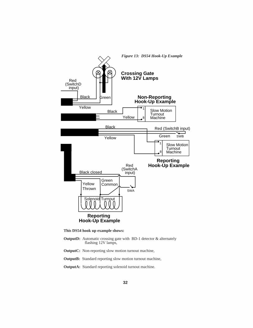
Figure 13: DS54 Hook-Up Example
This DS54 hook up example shows:
OutputD: Automatic crossing gate with BD-1 detector & alternately flashing 12V lamps,
OutputC: Non-reporting slow motion turnout machine,
OutputB: Standard reporting slow motion turnout machine,
OutputA: Standard reporting solenoid turnout machine.
32

The SwitchA input was used because it is wired into the same 4 wire cablegoing to the turnout, & is readily available at the solenoid turnout being set upfor feedback.
SwitchA input is being used solely to generate a turnout feedback message toLocoNet & is not causing any changes to OutputA. This feedback message willbe sent any time SwitchA input sees a change, because a LEVEL type of trig-gering is used for SwitchA input. Level triggering will cause a trigger on bothOFF to ON & ON to OFF input changes. In this way the DS54 will report anytime the turnout change from closed to thrown or vice-versa.
Note that this single feedback microswitch, SWA, can only positively reportthat the turnout is closed & will not report that the turnout is jammed, unsafe orin transit. You can arrange the AuxA input (being used in this example just totoggle OutputA, as a local turnout control) to positively report the thrown posi-tion of the turnout.
An example of this exact turnout feedback reporting is given in Figure 12. Inthis case the system can tell that the turnout is positively closed, positivelythrown or is "unsafe/in-transit". If you need this level of feedback certainty,you can achieve it by using both inputs as shown in Figure 12. When usingexact position reporting, the system controller or any device on LocoNet canassume the turnout is unsafe in the period between a feedback message sayingone of the inputs has changed to OFF (the turnout is moving from a knownsafe state) & the next feedback message from this switch address showing apositive ON or exact thrown or closed position is seen.
The LocoNet convention for turnout feedback message reporting is that theSwitch_ input ON reports a turnout is positively closed. The Aux_ input can beused either as the thrown indicator when ON, or could be used to report theposition of a different manual turnout or other device. If you want to use theAux_ input type for this thrown or exact position reporting, you will need tosetup the Aux_ message type for exact feedback. The system controller caninfer from this DS54 setting to interpret this meaning, since the default mean-ing for the Aux_ input is that it is NOT being used as a for exact thrown feed-back indication, but is available for independent use, such as reporting on ahand-operated turnout setting or local turnout control.
Figure 12 shows using external turnout contacts (e.g., a microswitch) to indi-cate to the DS54 the turnout position. It is also possible to place direct contactson the turnout so that when the points are in the correct position they connectthe Track Power (DCC packets) via a diode (D1) & capacitor (C1) to the DS54Switch_ input or Aux_ input line, as a "direct point sense input." This avoidsthe friction & use of an external microswitch, if a contact is readily made. As also shown in Figure 12, it is possible to isolate the turnout points, PA &
33

PB and use their connection to either of the powered rails to signal the turnoutposition. In this method you will need to isolate the two points PA & PB withgaps at XA & XB so the turnout is "non power-routing" (always best withDCC) to the rest of the powered rails. Be very careful with this method, sincethe rail sections PA & PB when set, are only being powered via a small lowpressure contact area to the adjacent rail & may not be able to carry the fullDCC load current when being jostled by wheels rolling over them.
11.0 DS54 CV Programming Steps
The DS54 can be programmed using a programming track or on the layoutafter it is installed. If you choose to program the DS54 after it is installed onthe layout, you must remove all DCC equipped locomotives, remove DS54auxiliary power, disconnect the 9 pin DS54 input plug and all 4 DS54 out-puts before you program DS54s. Because of this, Digitrax strongly recom-mends that the DS54 be programmed and tested before installation on the lay-out.
1. Plan how you want to use the DS54. Determine which CVs and CVvalues you want to program using the tables in this manual. At theend of this manual there are four blank forms that detail all CVsused to control each of the DS54’s function cells. Make copies foreach DS54 on the layout & use them in planning the CV settings forsetting up each function cell of the DS54. Once you know what youwant a particular DS54 to do, use the charts provided in this manualto look up the CVs and determine which CV values need to pro-grammed to accomplish your goal. Write them down on the formsand proceed to steps 2-8 below to program the DS54.
2. Move the CV Program Enable Link so that both pins PA & PB arecovered to enable programming.
3. Connect the DS54 to the programming track as shown in Figure 7 orif the DS54 is already installed on the layout and you want to pro-gram it directly on the layout, remove all DCC equipped locomo-tives, remove DS54 auxiliary power, disconnect the 9 pin DS54input plug and all 4 DS54 outputs before programming DS54s.
4. Put the system into programming mode. 5. Follow the instructions for the throttle you are using to select the CV
and CV Value to program 6. Repeat step 5 for as many CVs and their CV values as you want to
program.7. When you are finished programming, exit the programming mode. 8. Move the CV Program Enable Link so that only one pin is covered to
disable programming mode on the DS54.12.0 DS54 Basic Configuration Variables and Values
34

The DS54 has several kinds of configuration variables or CVs that let you setup how the DS54 will operate.
Hexadecimal and decimal notation: In this manual CVs are shown as deci-mal numbers and CV values are shown as hexadecimal and decimal numbers inthe following format x##/###. For example x20/032 means hex 20 or decimal032. When you use a Digitrax DT100 or DT200 throttle to program CVs theCV values will be displayed on the throttle as hexadecimal numbers. If you areusing a DT300 or DT100 you can display the CV values as either hex or deci-mal numbers. When the numbers are decimal, you will see three digits in thedisplay, when the number displayed is hexadecimal you will see an “x” beforethe two digits displayed. Please consult the hex to decimal conversion table(Table XI)at the end of this manual to translate the hex digits to decimal.
12.1 DS54 Output Type CVs
DS54 Output type CVs determine how the output from each function cell onthe DS54 will work. These are the CV numbers associated with each output.
Output Type CV Values: The following tables list the CV values that are usedto set up the DS54’s output types. Decide the type of output you need, find thecorrect CV number for the output you want to program from Table I and thecorrect CV value for the type you want to set up in Table II and program thechosen CV number to the chosen CV value.
Table I: Output Type CVs: CV03, CV04, CV05, CV06
CV# Usage Value range (default x00/000)
Defined by
CV03 Output Type for A x00-x27/000-039 Table II CV04 Output Type for B x00-x27/000-039 Table II CV05 Output Type for C x00-x27/000-039 Table II CV06 Output Type for D x00-x27/000-039 Table II
35

Table II: CV03, CV04, CV05, & CV06 Values for setting up the type of output and the duration of the pulse or blink rate for lamps for each function cell A, B, C, & D on the DS54.
CV Value
Output Type Duration Use With
x00 (default)
Pulse retriggerable 0.125 sec Solenoid
x01/001 Pulse retriggerable 0.25 sec Solenoid x02/002 Pulse retriggerable 0.35 sec Solenoid x03/003 Pulse retriggerable 0.5 sec Solenoid x04/004 Pulse retriggerable 0.625 sec Solenoid x05/005 Pulse retriggerable 0.75 sec Solenoid x06/006 Pulse retriggerable 0.9 sec Solenoid x07/007 Pulse retriggerable 1 sec Solenoid x08/008 Pulse retriggerable 2 secs Solenoid x09/009 Pulse retriggerable 3 secs Solenoid x0A/010 Pulse retriggerable 4 secs Solenoid x0B/011 Pulse retriggerable 5 secs Solenoid x0C/012 Pulse retriggerable 6 secs Solenoid x0D/013 Pulse retriggerable 7.5 secs Solenoid x0E/014 Pulse retriggerable 10 secs Solenoid x0F/015 Pulse retriggerable 12 secs Solenoid
CV Value
Output Type Duration Use With
x10/016 Pulse no-retrigger 0.125 sec Solenoid x11/017 Pulse no-retrigger 0.25 sec Solenoid x12/018 Pulse no-retrigger 0.35 sec Solenoid x13/019 Pulse no-retrigger 0.5 sec Solenoid x14/020 Pulse no-retrigger 0.625 sec Solenoid x15/021 Pulse no-retrigger 0.75 sec Solenoid x16/022 Pulse no-retrigger 0.9 sec Solenoid x17/023 Pulse no-retrigger 1 sec Solenoid x18/024 Pulse no-retrigger 2 secs Solenoid x19/025 Pulse no-retrigger 3 secs Solenoid x1A/026 Pulse no-retrigger 4 secs Solenoid
36

12.2 DS54 Basic CV Programming Example
Set up DS54 Outputs for 1 Solenoid Turnout Machine, 2 Slow MotionTurnout Machines & 1 Crossing Gate with Detector
1. Determine which CVs and CV values you want to program using thetables in this manual.
2. Move the CV Program Enable Link so that both pins PA & PB arecovered to enable programming.
3. Connect the DS54 to the programming track or if the DS54 is alreadyinstalled on the layout and you want to program it directly on thelayout, remove all DCC equipped locomotives, remove DS54 auxil-iary power, disconnect the 9 pin DS54 input plug and all 4 DS54
Table II (continued): CV Value
Output Type Duration Use With
x1B/027 Pulse no-retrigger 5 secs Solenoid x1C/028 Pulse no-retrigger 6 secs Solenoid x1D/029 Pulse no-retrigger 7.5 secs Solenoid x1E/030 Pulse no-retrigger 10 secs Solenoid x1F/031 Pulse no-retrigger 12 secs Solenoid
CV Value
Output Type Duration Use With
x20/032 Static Steady Slow motion
CV Value
Output Type Duration Use With
x21/033 Blinking 0.125 sec Lamp x22/034 Blinking 0.25 sec Lamp x23/035 Blinking 0.5 sec Lamp x24/036 Blinking 1 sec Lamp x25/037 Blinking 2 secs Lamp x26/038 Blinking 4 secs Lamp x27/039 Blinking 8 secs Lamp x28/040 through xFF/255
Reserved for future features
37

outputs before you program DS54s. 4. Put the system into programming mode. 5. Using a throttle, select the CV you want to program.6. Select the CV value you want to program for the CV. 7. Press the appropriate keys on the throttle to program the CV you
selected to the CV value you have chosen.8. Repeat steps 5 through 7 for as many CVs and their CV values as you
want to program.9. When you are finished programming, exit the programming mode.10. Move the CV Program Enable Link so that only one pin is covered
to disable programming mode on the DS54.11. Install or reconnect the DS54 on the layout and wire the turnout
machines, crossing gate and fascia mounted switches as shown inFigure 13.
Program the DS54’s outputs for this example as follows:
A. Set up OutputA as a solenoid with a 1/4 second non-retriggerable out-put. Table I lists the CVs that determine the output type for each function cell.Table I shows that the CV value programmed into CV03 determines the outputtype for function cell A.Table II lists the possible CV values and their effects. From Table II, a CVvalue of x11/017 will operate a solenoid turnout machine with a 1/4 secondnon-retriggerable pulse. Follow the programming steps above to programCV03 to a value of x11/017.
B. Set up OutputB to operate a slow motion turnout machine.Refer to Table I to determine that the output type CV for OutputB is CV04.Refer to Table II to determine that CV value that will give the result desired.In this case the CV value is x20/032. Again, follow the steps outlined above toprogram CV04 to a value of x20/032.
C. Set up OutputC to operate a slow motion turnout machine. Refer toRefer to Table I to determine that the output type CV for OutputC is CV05.Refer to Table II to determine that CV value that will give the result desired.In this case the CV value is x20/032.Again, follow the steps outlined above to program CV05 to a value ofx20/032.
D. Set up OutputD to operate a lamp that is blinking with a 1 secondduration when the output is turned ON (closed=ON). Refer to Table I todetermine that the output type CV for OutputC is CV06. Refer to Table II todetermine that CV value that will give the result desired. In this case the CVvalue is x24/036.
38

Again, follow the steps outlined above to program CV06 to a value ofx24/036.
By programming the 4 Output type CVs (CV03, CV04, CV05 or CV06) youhave set up the output types needed for each of the DS54’s outputs for thisexample.
This example is continued in Section 13.3 where programming the inputson the DS54 is covered.
13.0 Intermediate DS54 CVs
13.1 Trigger/Task Configuration Variables
Each of the 8 DS54 inputs have a CV number that controls how they respondto input signals. The response is defined by a trigger and a task. An input isON if it is connected to greater than +6 Volts with respect to DS54 negativecommon line up to a maximum of 20Volts. A voltage from 0 to less than +6Volts is considered OFF. If an input line is left disconnected it is by definitionOFF.
Digitrax recommends programming these CV values in hex as shown here. Toprogram in decimal, compute the hex number and convert it using the conver-sion table (Table XI) at the end of this manual.
The trigger/task CV values in hex are made up of two digits. The left digit setsup the trigger conditions that must occur to initiate a task specified by the rightdigit of the CV value in hex. The right digit sets up the task that will occurwhen the trigger conditions are met. Once you determine this two digit hex CV
Table III: DS54 Input Trigger/Task CV's, CV value ranges & associated wire colors
CV # Input Values
(00 default) Input wire color
Pin
CV33 AuxA x00-xFF Orange 3 CV34 SwitchA x00-xFF Blue 4 CV35 AuxB x00-xFF Black 8 CV36 SwitchB x00-xFF Violet 9 CV37 AuxC x00-xFF Yellow 6 CV38 SwitchC x00-xFF Gray 7 CV39 AuxD x00-xFF Green 1 CV40 SwitchD x00-xFF Red 2 Common Lead
White 5
39
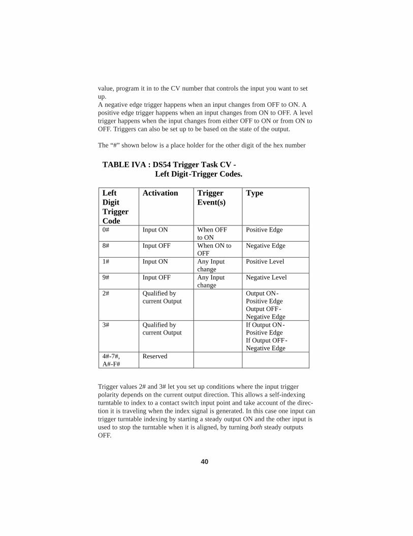
value, program it in to the CV number that controls the input you want to setup.A negative edge trigger happens when an input changes from OFF to ON. Apositive edge trigger happens when an input changes from ON to OFF. A leveltrigger happens when the input changes from either OFF to ON or from ON toOFF. Triggers can also be set up to be based on the state of the output.
The “#” shown below is a place holder for the other digit of the hex number
Trigger values 2# and 3# let you set up conditions where the input triggerpolarity depends on the current output direction. This allows a self-indexingturntable to index to a contact switch input point and take account of the direc-tion it is traveling when the index signal is generated. In this case one input cantrigger turntable indexing by starting a steady output ON and the other input isused to stop the turntable when it is aligned, by turning both steady outputsOFF.
TABLE IVA : DS54 Trigger Task CV - Left Digit-Trigger Codes.
Left Digit Trigger Code
Activation Trigger Event(s)
Type
0# Input ON When OFF to ON
Positive Edge
8# Input OFF When ON to OFF
Negative Edge
1# Input ON Any Input change
Positive Level
9# Input OFF Any Input change
Negative Level
2# Qualified by current Output
Output ON-Positive Edge Output OFF-Negative Edge
3# Qualified by current Output
If Output ON-Positive Edge If Output OFF-Negative Edge
4#-7#, A#-F#
Reserved
40
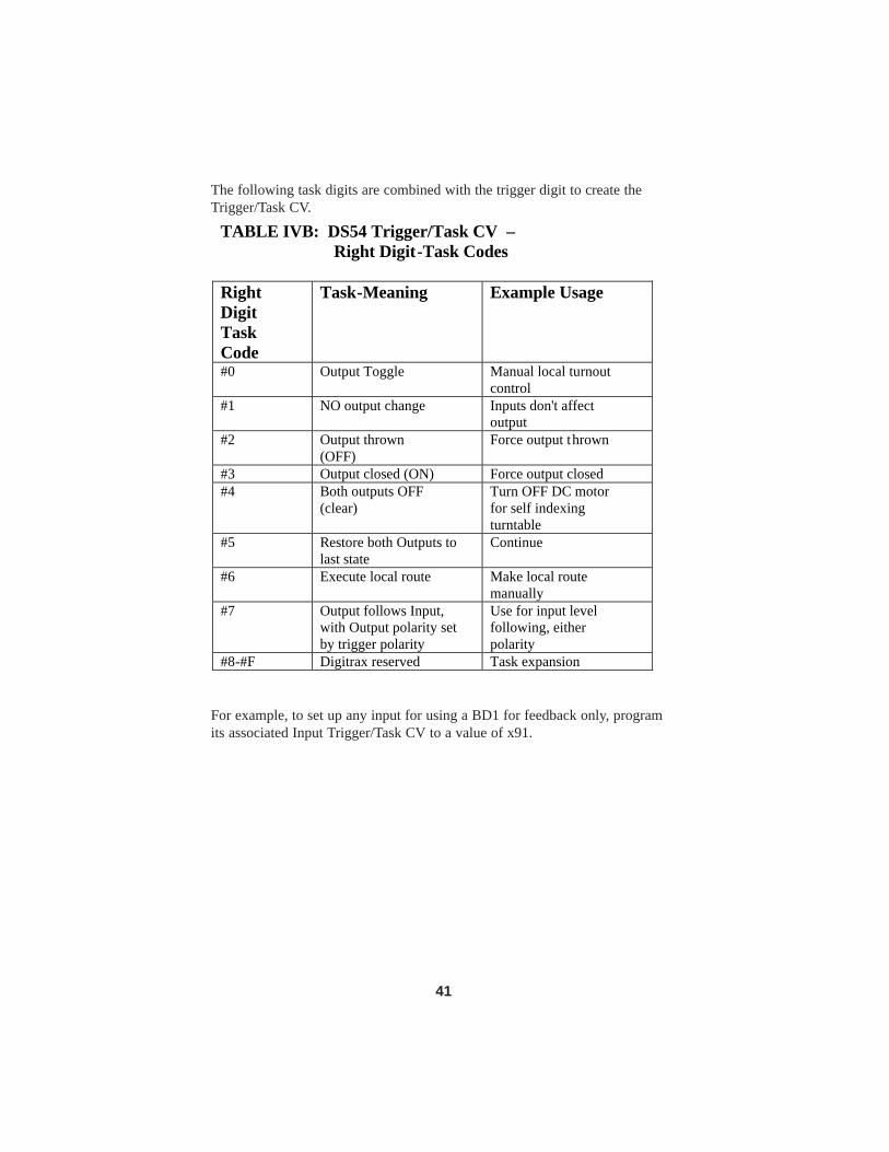
The following task digits are combined with the trigger digit to create theTrigger/Task CV.
For example, to set up any input for using a BD1 for feedback only, programits associated Input Trigger/Task CV to a value of x91.
TABLE IVB: DS54 Trigger/Task CV – Right Digit-Task Codes
Right Digit Task Code
Task-Meaning Example Usage
#0
Output Toggle Manual local turnout control
#1 NO output change Inputs don't affect output
#2 Output thrown (OFF)
Force output thrown
#3 Output closed (ON) Force output closed #4 Both outputs OFF
(clear) Turn OFF DC motor for self indexing turntable
#5 Restore both Outputs to last state
Continue
#6 Execute local route Make local route manually
#7 Output follows Input, with Output polarity set by trigger polarity
Use for input level following, either polarity
#8-#F Digitrax reserved Task expansion
41

13.2 Message Type CVs
When the input Trigger conditions are met, the DS54 can send a number of dif-ferent messages to LocoNet. These messages are set up by programmingMessage type CVs. If LocoNet is not operating or disconnected, the DS54 willcontinue with all its normal tasks and queue all messages till the LocoNet con-nection is reestablished. A DCC RESET will clear all pending messages. Notethat the DS54 device messages are a higher priority than any throttle update, sosensors are always guaranteed fastest access to LocoNet.
Table V: DS54 Message Type CV's
CV # USAGE: Message Type
Default Code
Defined by
CV41 AuxA Input message 00 Table VI CV42 SwitchA Input &
OutputA change messages 00 Table VI
CV43 AuxB Input message 00 Table VI CV44 SwitchB Input & OutputB
change msgs 00 Table VI
CV45 AuxC Input message 00 Table VI CV46 SwitchC Input & OutputC
change msgs 00 Table VI
CV47 AuxD Input message 00 Table VI CV48 SwitchD Input and
OutputD change messages 00 Table VI
42

Notes for Message type CV Values:*Note that the output on change message can only be enabled in the CV entryfor the Switch_ Input message CV for a particular cell. For example, CV44can use these x81-x83 CV values to allow output on change messages for cellB (OutputB). For the Aux input lines, message type CV values x80-x83 willnot allow output change messages for their cell. Output on change messageswill only be generated if a local input condition within the DS54 has changedthe output.
** The Exact feedback message type only applies to Aux_ inputs (not Switch_inputs). There is no exact status effect for Switch_ inputs.
Table VI: DS54 Message Type CV Values CV Val (hex)
LocoNet Message Sent Result
x00 Sensor input message Input treated as general sensor
x01 No LocoNet messages this cell No messages at all x02 Turnout feedback message Inupt is turnout
position feedback x03 Cascaded turnout request Send cascade
turnout request message
x04 System Power ON/Off Send ON/OFF based on trigger
x05 System STOP/RUN Send STOP/RUN based on trigger
x06-x09 Digitrax reserved x0A** Exact turnout feedback
message AUX input is exact feedback
x0B-x7F Digitrax reserved x80* Output state & sensor input
message Output message on output change
x81* Output state message Send output message, output changed
x82* Output state & turnout feedback message
As well as message type defined by lower digit code
x83* Output state & cascaded turnout request
x84-x89 Digitrax reserved x8A Exact turnout feedback
message AUX input is exact feedback
x8B-xFF Digitrax reserved
43

The Cascaded Turnout requests refer to an associated pair of CVs, in the rangeCV57 to CV72, that define a turnout change request to be sent via LocoNet tothe system master command station when this input is triggered. This willresult in a turnout command being generated and sent to the DCC rails, basedon the turnout’s switch address and position set up in the input's associatedCascade Turnout request CVs. Note that this switch address could be defined,for example in a command station, as a chain of MU'ed turnouts (or a route)that would then be executed by this "cascade" type message.
Message type CV values x04 and x05 are special codes. Messages type CVvalues of x04 and x05 can be used to create various system control buttons orexternal switches, like emergency STOP, POWER ON or POWER OFF, con-nected via a DS54. They send messages based on the state of the input whenthe trigger conditions are met.
Message Type x04:If the Input is ON at trigger, the message will be Power ONIf the Input is OFF at trigger, the message will be Power OFF.
In this case, if the Trigger to be Positive edge (Trig/Task=x0#) is chosen, thePower ON message will be sent if a momentary switch is used on the input toan ON voltage level. In the case of LEVEL trigger input (Trig/Task=x1#)Power On will be sent when the input is ON, and Power OFF will be sentwhen the input is OFF (unconnected)
Message Type x05:If the Input is ON at trigger, the message will be STOP (IDLE the layout)If the Input is OFF at trigger, the message will be START (actually Power ON)
Note that the Task codes that operate on local Outputs and the Message Typecodes are independent in operation but are executed by the same input triggerconditions.
LocoNet messages distinguish between Output state message, Feedback mes-sage and Sensor Message types. In all cases the DS54 stationary decoderaddress and 4 related switch addresses of the output or input are contained inthe message to uniquely identify the source of the message.
44
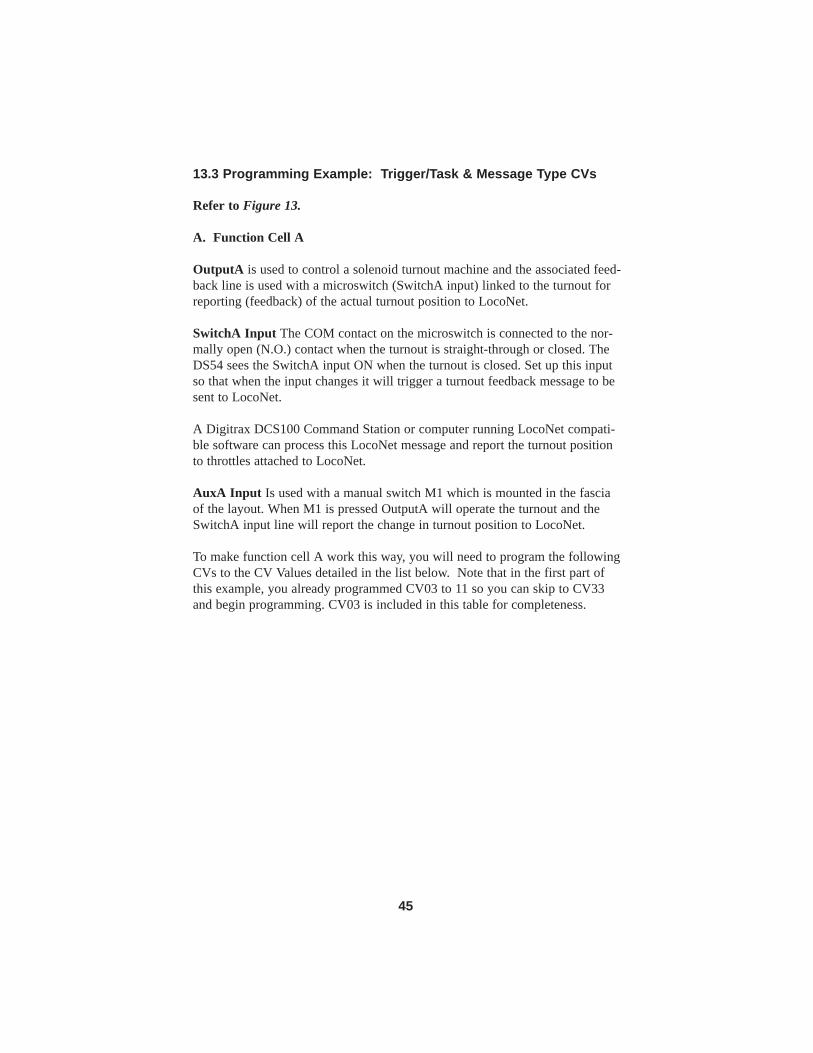
13.3 Programming Example: Trigger/Task & Message Type CVs
Refer to Figure 13.
A. Function Cell A
OutputA is used to control a solenoid turnout machine and the associated feed-back line is used with a microswitch (SwitchA input) linked to the turnout forreporting (feedback) of the actual turnout position to LocoNet.
SwitchA Input The COM contact on the microswitch is connected to the nor-mally open (N.O.) contact when the turnout is straight-through or closed. TheDS54 sees the SwitchA input ON when the turnout is closed. Set up this inputso that when the input changes it will trigger a turnout feedback message to besent to LocoNet.
A Digitrax DCS100 Command Station or computer running LocoNet compati-ble software can process this LocoNet message and report the turnout positionto throttles attached to LocoNet.
AuxA Input Is used with a manual switch M1 which is mounted in the fasciaof the layout. When M1 is pressed OutputA will operate the turnout and theSwitchA input line will report the change in turnout position to LocoNet.
To make function cell A work this way, you will need to program the followingCVs to the CV Values detailed in the list below. Note that in the first part ofthis example, you already programmed CV03 to 11 so you can skip to CV33and begin programming. CV03 is included in this table for completeness.
45

In this example, the SwitchA input associated with OutputA is used instead ofthe AuxA input. The AuxA input could have been programmed for the sametask, since both AuxA input & SwitchA input can cause changes to OutputA.The SwitchA input was used in this example because it is wired into the 4 wirecable going to the turnout and is readily available at the solenoid turnout beingset up for feedback.
In this example the SwitchA input is used only to generate a turnout feedbackmessage to LocoNet & is not set up to cause any changes to OutputA. Thisfeedback message will be sent any time SwitchA input sees a change, becausea level type of triggering for SwitchA input has been chosen. Level triggeringwill cause a trigger when either OFF to ON or ON to OFF input changes occur.With level triggering the DS54 will report any time the turnout change fromclosed to thrown or vice-versa.
This single feedback sensor switch, SWA, can only positively report that theturnout is closed. It can not report that the turnout is jammed, unsafe or in tran-sit.
Set up function cell A to control a solenoid turnout
machine with standard turnout position reporting and fascia mounted turnout control button.
CV# CV Val
hex/dec Usage Effect Comment
CV03 x11/017 Output type for A
Non-retriggerable 0.25 second pulse for solenoid
Setup for solenoid turnout on OutputA
CV33 x00/000 AuxA input Trig/task
Change OutputA when switch M1 pressed
Local OutputA control
CV34 x11/017 SwitchA input Trig/task
Trigger on level, no output task-message only
OutputA feedback
CV41 x01/001 AuxA input message type
No messages sent
SwitchA input reports feedback
CV42 x02/002 SwitchA message type
Send OutputA feedback message
OutputA feedback message
46

In this example the AuxA input is used to operate the turnout attached toOutputA from a manual switch mounted in the fascia panel. This allows for theturnout to be operated either from the manual switch or from the throttle.
B. Function Cell B
OutputB is used to control a slow motion turnout machine with a turnout feed-back sensor microswitch, SWB.
SwitchB Input The COM contact on the microswitch is connected to the nor-mally open (N.O.) contact when the turnout is straight-through or closed. TheDS54 sees the SwitchB input line ON when the turnout is closed. Set up thisinput so that when the input changes it will trigger a turnout feedback messageto be sent to LocoNet.
AuxB Input Is used with a manual switch M2 which is mounted in the fasciaof the layout. When manual switch M2 is pressed Output B will operate theturnout and the SwitchB input line will report the change in turnout position toLocoNet.
To make function cell B work this way, program the following CVs to the CVValues detailed in the list below. Note that in the first part of this example, youalready programmed CV04 to x20/032 so you can skip to CV35 and begin pro-gramming. CV04 is included in this table for completeness.
47

Set up function cell B to control a slow motion turnout machine with standard turnout position reporting and
fascia mounted turnout control button. CV# CV Val
hex/dec Usage Effect Comment
CV04 x20/032 Output type for B
Steady output type
Setup for slow motion OutputB
CV35 x00/000 AuxB input Trig/task
Change OutputB when switch M2 pressed
Local OutputB control
CV36 x11/017 SwitchB input Trig/task
Trigger on level, no output task-message only
OutputB feedback
CV43 x01/001 AuxB input message type
No messages sent
SwitchB input reports feedback
CV44 x02/002 SwitchB message type
Send OutputB feedback message
OutputB feedback message
48

C. Function Cell C
OutputC is set up to control a slow motion turnout machine without turnoutfeedback.
SwitchC Input the red wire in the DS54 output cable is not connected
AuxC Input is used with a manual switch M3 which is mounted in the fasciaof the layout. When M3 is pressed OutputC will operate the turnout.
For OutputC, a positive feedback turnout input is not being used, but a messagecan still be sent to LocoNet indicating that OutputC has changed state. This canbe done with either the AuxC local control input or if the Local Route triggered(on SwitchC input) changes OutputC. In this case, the LocoNet device trackingturnout states will mark the turnout in a known Output state, but without posi-tive feedback. If there is a command over the DCC rails that changes OutputC,there will be NO messages triggered, since it is NOT a Local input event & the
Set up function cell C to control slow motion turnout
machine with no turnout position reporting and a fascia mounted turnout control button.
CV# CV Val
hex/dec Usage Effect Comment
CV05 x20/032 Output type for C
Steady output Setup for OutputC Slow Motion type
CV37 x00/000 AuxC input Trig/task
Change OutputC when switch M3 pressed
Local OutputC control
CV38 x06/006 SwitchC input Trig/task
Trigger on edge, generate local route
Local Route from switch M4
CV45 x01/001 AuxC message type
No messages sent
No feedback
CV46 x81/129 SwitchC message type
Output change message only
Update turnout output state only
49

LocoNet Master Command station issued the request & hence knows theintended turnout position. Note that with CV54, OutputD was not included inthe local route and A was set to closed and B & C were set to thrown whenmanual switch M4 is pressed. To make this work, program the following CVsand CV Values.
CV# CV Val
hex/dec Usage Effect Comment
CV53 x00/000 AuxC Local Route
None Not used for Route
CV54 x71/113 Switch C Input
Include Outputs Route A+B+C, Not D
OutputA Local closed, B+C thrown
50

D. Function Cell D
OutputD is used as an automatic crossing gate controller with occupancydetection.
SwitchD Input is used to monitor a Digitrax BD1 occupancy detector.
AuxD Input is used with a fascia mounted manual switch M5 that is set up toshut off layout power.
The D output type is configured to operate as a blinking output when the out-put is ON (closed). The Trigger/Task configuration for the SwitchD input issetup to turn OutputD ON (lights blink) when the occupancy detector is ON,showing a locomotive is occupying the protected detection section. If OutputDshould be OFF (non-blinking) when SwitchD input is ON (BD1 detection sec-tion occupied), change the Trigger to Negative Level, i.e., CV40=x97/151, togive the output sense a reversed meaning. In this example, a DCC command for OutputD to be closed or ON will remote-
Set up function cell D as an automatic crossing gate controller with block detection and a fascia mounted
manual switch to shut layout power off. CV# CV Val
hex/dec Usage Effect Comment
CV06 x24/036 Output type for D
Blinking (alternating) output at 1 second period
Setup for lights for crossing gate
CV39 x80/128 AuxD input Trig/task
Power OFF when M5 pressed, Negative Edge
Emergency Power OFF
CV40 x17/023 SwitchD input Trig/task
Trigger on level, have output D ON if BD1 is ON
Block detector link to crossing gate lights
CV47 x04/004 AuxD message type
Send power off message when AuxD goes OFF
Press & release M5 for power OFF
CV48 x00/000 SwitchD message type
Send sensor message from block detector
For signal system & CTC panels
51

ly start the signal lights flashing & the thrown or OFF command will turn OFFthe signal lights.
Set up the SwitchD input to generate a LocoNet sensor message when it detectsthat the detection section is occupied (ON) & also when the detection sectionbecomes unoccupied (OFF), this results from the Trigger being set for leveltype (both changes). This ensures the system will be updated as to the currentstate, occupied or not-occupied, of the occupancy detector.
13.4 Using a Digitrax BD1 Occupancy Detector
The Digitrax BD1 has internal "anti-chatter filtering" to ensure that when thelocomotive crosses the gap into the detected section, the uncertainties of whereit is picking up track power from are filtered out. The occupancy detector willonly operate (ON) when the locomotive (or current load) is inside the detectedsection and there are no shorts across the isolation gaps.
The BD1 is a high sensitivity occupancy detector designed for DCC operations,and needs a maximum resistance across the tracks of 15 K ohms to operate ONproperly. Naturally, you should NOT connect any other devices or loads acrossthe detection section that you wish the BD1 to report occupancy status of, oth-erwise the BD1 will not be able to report OFF or “clear”.
The thin black wire on the BD1 be attached only to the heavy black DS54common wire. The thin red wire from the BD1 should be attached to the DS54input lead chosen for the task. The short heavy leads of the BD1 are connectedto carry the track current from a powered track section INTO the detection sec-tion where the detection rail has been gapped at both ends of just one of therails. For correct operation it is important that the heavy lead marked "Block"be connected to the isolated rail of the detection section. To lower the sensitivi-ty of the BD1 occupancy detector, you can connect a 1/4 watt resistor in therange of 47 ohms to 1K ohms across the BD1's heavy input leads, the exactvalue can be determined by trial for the sensitivity you desire. The output ofthe BD1 can be checked with a regular DC voltmeter. If the BD1 red wire isover +6 volts with respect to the black wire, the detection section will bereported as occupied or "ON". You can put a 10K 1/4 watt resistor across thedetection section to verify that it is working correctly, when the voltmeter isconnected and the BD1 black and red leads are correctly connected to a DS54.
Figure 14 shows how multiple detection sections can be handled by a singleBD1 to automate a more complex version of an automatic crossing gate. In thisexample, red LEDs are used as the crossing gate lights. Two diodes, D1 andD2, are used to energize a solenoid to operate the gate and operate a soundmodule from the output voltage when the lights are flashing.
52

Figure 14: Automatic crossing gate with multiple detection sections
To DS54Output D
YellowRed
Green
Black
BD-1
Block
LED 1 LED 2
D1
D2
+15V to +20V
OptionalCrossingGate Solenoid1 amp max
OptionalBellSoundModule
+
-IN4001
R11kohm1/2 wattResistor
Detection SectionsPower Bypass 1
Track 1
Track 2(optional)
Track 3(optional)
Rail A Rail BTo DCCBooster
Power Bypass 2
Power Bypass 3
Single GapsOnly
BlackTo DS54 NegativeCommon (22 AWGBlack Wire)
53

14.0 Route Control CVs (Advanced)
14.1 Local Route Control CVs
A Route can be set up by linking stationary decoders together so that they per-form several operations based on a single command sent from the commandstation. It is sort of like “consisting” turnouts. A Local Route is one that ishandled by a single DS54 without intervention from the command station.
Any DS54 input can be set up to generate a local route. A local route is a taskthat can include any or all of a particular DS54’s 4 function cells and define thesettings these function cell outputs will have when that route is operated.
The outputs that are included in a local route are set up in the left digit of theCV value programmed into the Local Route Set up CV. For any cell or cellsthat are included in the route by the left digit, the right digit of the CV valuecontrols whether the output will be in the closed (ON) or thrown (OFF) posi-tion when the route is activated. The left (inclusion) and right (position) digitsare combined to form the CV value in hex to program into the Local Route Setup CV.
The local route will be executed when the trigger condition for this input linehas been met. It is sensible to only trigger a local route on an edge and not alevel trigger condition since the route is executed as a fixed predefined pattern,and having 2 successive activations on a single momentary key press is redun-dant.
When programming these values, Digitrax recommends that you use hex num-bers. Alternately, you can compute the hex number and use the conversiontable (Table XI) to determine the decimal value to program.
Table VII: DS54 Local Route CV's CV# Local Route Set up for CV49 AuxA input CV50 SwitchA input CV51 AuxB input CV52 SwitchB input CV53 AuxC input CV54 SwitchC input CV55 AuxD input CV56 SwitchD input
54

In Table VIIIA the “#” is a place holder that will be filled in with the rightdigit that determines turnout position from Table VIIIB.
Table VIIIA: DS54 Local Route Set up CV Value: Left Digit Function Cells Included in Local Route
Left Digit
Function Cells/Outputs included in Local Route
0# none 1# A 2# B 3# A+B 4# C 5# A+C 6# C+B 7# A+B+C 8# D 9# D+A A# D+B B# D+A+B C# D+C D# D+C+A E# D+B+C F# D+C+B+A
55

In Table VIIIB the “#” is a place holder that will be filled in with the left digitthat determines turnout position from Table VIIIA.
Table VIIIB: DS54 Local Route Set Up CV Right Digit Turnout Position Control
Right Digit
Enabled Cells/Outputs in Route to Set ON/CLOSED. (Un-named are made OFF/THROWN)
#0 none (all OFF/THROWN) #1 A #2 B #3 A+B #4 C #5 A+C #6 C+B #7 A+B+C #8 D #9 D+A #A D+B #B D+A+B #C D+C #D D+C+A #E D+B+C #F D+C+B+A (all ON/CLOSED)
56

14.2 Cascade Turnout Control Messages
A Cascaded route is the operation of one or more turnouts by a function cellwhen it sends a request for the command station to initiate the required action.
Cascade turnout control messages can be set up to be sent to LocoNet when theinput trigger condition is met for any of the DS54’s 8 input lines. These mes-sages are controlled by a pair of CVs, the Cascade Control CV and the CascadeAddress CV as follows:
Cascade Control CV: this CV has 3 valid CV values-xB0, x90, or x00. Allother values are reserved by Digitrax for future expansion.
Table IX: Cascade Turnout Request Message CV's CV Number
Use Default Range (hex)
CV57 AuxA Cascade Control 00 xB0 or x90 or x00 CV58 AuxA Cascade Address 00 x00-x7F CV59 SwitchA Cascade
Control 00 xB0 or x90 or x00
CV60 SwitchA Cascade Address
00 x00-x7F
CV61 AuxB Cascade Control 00 xB0 or x90 or x00 CV62 AuxB Cascade Address 00 x00-x7F CV63 SwitchB Cascade
Control 00 xB0 or x90 or x00
CV64 SwitchB Cascade Address
00 x00-x7F
CV65 AuxC Cascade Contr ol 00 xB0 or x90 or x00 CV66 AuxC Cascade Address 00 x00-x7F CV67 SwitchC Cascade
Control 00 xB0 or x90 or x00
CV68 SwitchC Cascade Address
00 x00-x7F
CV69 AuxD Cascade Control 00 xB0 or x90 or x00 CV70 AuxD Cascade Address 00 x00-x7F CV71 SwitchD Cascade
Control 00 xB0 or x90 or x00
CV72 SwitchD Cascade Address
00 x00-x7F
57

Cascade Address CV: This CV has a valid range of x00 to x7F. This numberis the hexadecimal value of the (Turnout number -1). e.g Turnout number 1would have a Cascade address of x00. See Table XI for Decimal to hexadeci-mal conversions
15.0 Reading Back CVs and CV Values
If you use a programming track and device, like a DCS100 or PR1, that canread back CVs and their values, you can place the Program Enable Link in theclosed position and hook up a Program Read Back Adapter as shown in Figure7. The Program Read Back Adapter consists of a 120 ohm 2 watt resistor con-nected to the yellow and black leads of one of the DS54’s outputs. The otherend of the resistor is connected to one of the programming track rails; it doesn'tmatter which one. (If you still have the resistor from the test kit that wasincluded in your starter set, you can use it for this purpose. You can also use a12V 5W automotive lamp instead of the resistor.)
Follow your system manual’s instructions for reading back CVs and their val-ues.
16.0 DS54 Troubleshooting Instructions
Be sure you understand how to do CV programming with the throttle youare using. CV values shown are 00 or 000 for decimal and x00 for hex. Readyour manual carefully to be sure you are using the appropriate values whenprogramming the DS54.
DT100 & DT200 throttles do not support decimal.
DT300 & DT400 throttles default to decimal but you can toggle between deci-mal and hex by clicking the right knob. You know you are in hex mode if thedisplay shows the value with an "x" prefix like “x00”. As you click the righthand knob, it toggles the value displayed as hex and decimal.
Table X: Cascade Control CV's Value Meaning x00/000 Cascade Turnout message disabled
(default) xB0/176 Change Cascade turnout number to
CLOSED (ON) x90/144 Change Cascade turnout number to
THROWN (OFF)
58
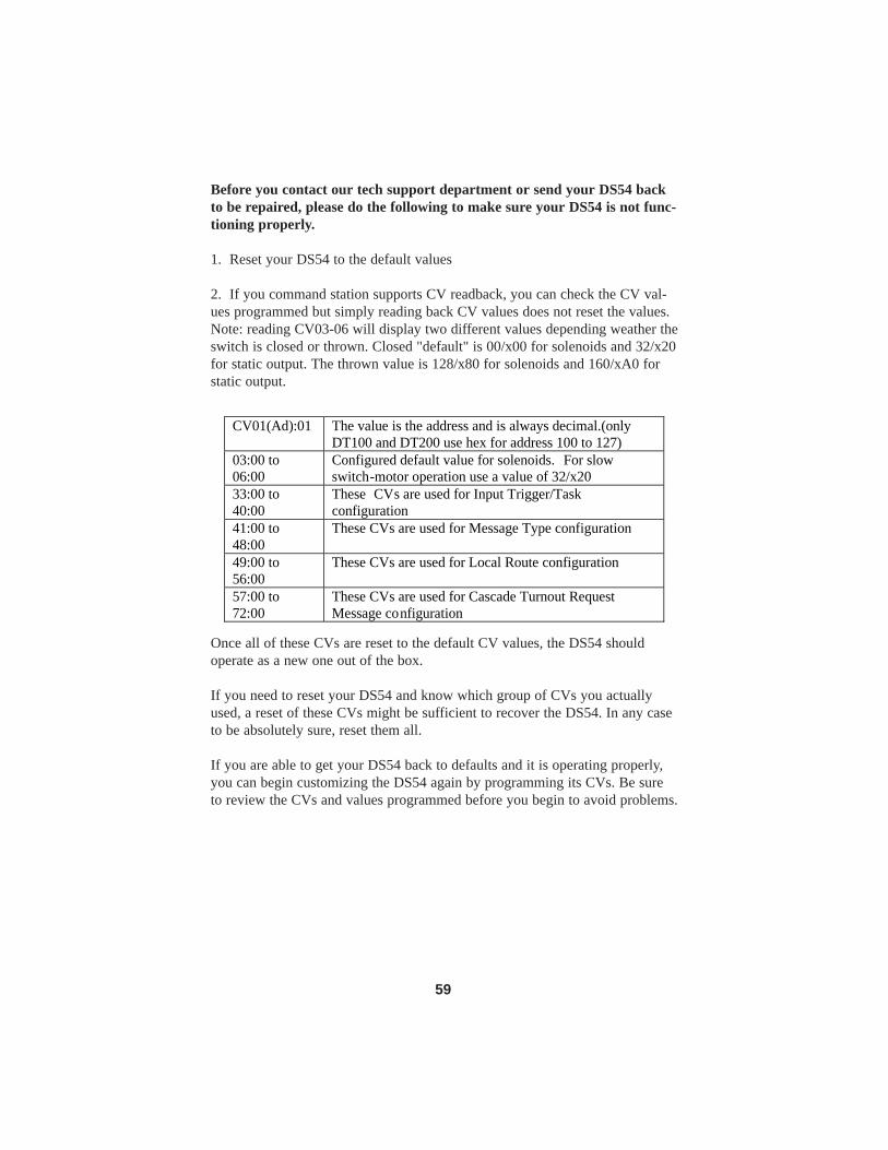
Before you contact our tech support department or send your DS54 backto be repaired, please do the following to make sure your DS54 is not func-tioning properly.
1. Reset your DS54 to the default values
2. If you command station supports CV readback, you can check the CV val-ues programmed but simply reading back CV values does not reset the values.Note: reading CV03-06 will display two different values depending weather theswitch is closed or thrown. Closed "default" is 00/x00 for solenoids and 32/x20for static output. The thrown value is 128/x80 for solenoids and 160/xA0 forstatic output.
Once all of these CVs are reset to the default CV values, the DS54 shouldoperate as a new one out of the box.
If you need to reset your DS54 and know which group of CVs you actuallyused, a reset of these CVs might be sufficient to recover the DS54. In any caseto be absolutely sure, reset them all.
If you are able to get your DS54 back to defaults and it is operating properly,you can begin customizing the DS54 again by programming its CVs. Be sureto review the CVs and values programmed before you begin to avoid problems.
CV01(Ad):01
The value is the address and is always decimal.(only DT100 and DT200 use hex for address 100 to 127)
03:00 to 06:00
Configured default value for solenoids. For slow switch-motor operation use a value of 32/x20
33:00 to 40:00
These CVs are used for Input Trigger/Task configuration
41:00 to 48:00
These CVs are used for Message Type configuration
49:00 to 56:00
These CVs are used for Local Route configuration
57:00 to 72:00
These CVs are used for Cascade Turnout Request Message configuration
59

60
The following four forms detail all CVs used to control each of the DS54’sfunction cells. Use them in planning the CV settings for setting up each func-tion cell of the DS54. Once you know what you want the DS54 to do, look upthe CVs and their values that you need to program in this manual. Write themdown here, program the decoder on the programming track, test the decoderand then install the decoder on the layout.
Table XI: Decimal to Hexadecimal Conversion Chart DEC HEX DEC HEX DEC HEX DEC HEX DEC HEX DEC HEX DEC HEX 00 00 39 27 78 4E 117 75 156 9c 195 c3 234 EA 01 01 40 28 79 4F 118 76 157 9d 196 c4 235 Eb 02 02 41 29 80 50 119 77 158 9E 197 c5 236 Ec 03 03 42 2A 81 51 120 78 159 9F 198 c6 237 Ed 04 04 43 2b 82 52 121 79 160 A0 199 c7 238 EE 05 05 44 2c 83 53 122 7A 161 A1 200 c8 239 EF 06 06 45 2d 84 54 123 7b 162 A2 201 c9 240 F0 07 07 46 2E 85 55 124 7c 163 A3 202 cA 241 F1 08 08 47 2F 86 56 125 7d 164 A4 203 cb 242 F2 09 09 48 30 87 57 126 7E 165 A5 204 cc 243 F3 10 0A 49 31 88 58 127 7F 166 A6 205 cd 244 F4 11 0b 50 32 89 59 128 80 167 A7 206 cE 245 F5 12 0c 51 33 90 5A 129 81 168 A8 207 cF 246 F6 13 0d 52 34 91 5b 130 82 169 A9 208 d0 247 F7 14 0E 53 35 92 5c 131 83 170 AA 209 d1 248 F8 15 0F 54 36 93 5d 132 84 171 Ab 210 d2 249 F9 16 10 55 37 94 5E 133 85 172 Ac 211 d3 250 FA 17 11 56 38 95 5F 134 86 173 Ad 212 d4 251 Fb 18 12 57 39 96 60 135 87 174 AE 213 d5 252 Fc 19 13 58 3A 97 61 136 88 175 AF 214 d6 253 Fd 20 14 59 3b 98 62 137 89 176 b0 215 d7 254 FE 21 15 60 3c 99 63 138 8A 177 b1 216 d8 255 FF 22 16 61 3d 100 64 139 8b 178 b2 217 d9 23 17 62 3E 101 65 140 8c 179 b3 218 dA 24 18 63 3F 102 66 141 8d 180 b4 219 db 25 19 64 40 103 67 142 8E 181 b5 220 dc 26 1A 65 41 104 68 143 8F 182 b6 221 dd 27 1b 66 42 105 69 144 90 183 b7 222 dE 28 1c 67 43 106 6A 145 91 184 b8 223 dF 29 1d 68 44 107 6b 146 92 185 b9 224 E0 30 1E 69 45 108 6c 147 93 186 bA 225 E1 31 1F 70 46 109 6d 148 94 187 bb 226 E2 32 20 71 47 110 6E 149 95 188 bc 227 E3 33 21 72 48 111 6F 150 96 189 bd 228 E4 34 22 73 49 112 70 151 97 190 bE 229 E5 35 23 74 4A 113 71 152 98 191 bF 230 E6 36 24 75 4b 114 72 153 99 192 c0 231 E7 37 25 76 4c 115 73 154 9A 193 c1 232 E8 38 26 77 4d 116 74 155 9b 194 c2 233 E9

61
DS54#_____ Function Cell A Turnout Address_______ Description of set -up: ___________________________________________________________________________________________________________________________________________________ CV# CV
Value Use Desired Effect/Comments
CV03
Output type
Trig
CV33 AuxA input Trigger/task
Task Trig
CV34 SwitchA Trigger/task
Task Msg type
CV41 AuxA message type Output msg?
Msg type
CV42 SwitchA message type Output msg?
Local route in A
CV49 AuxA
ON/Closed A Local route set up in A
CV50 SwitchA
On/Closed A
CV57 AuxA Cascade Control
Cascade effect
CV58 AuxA Cascade Address
Turnout # (hex value is # -1)
CV59 SwitchA Cascade Control
Cascade effect
CV60 SwitchA Cascade Address
Turnout # (hex value is # -1)

62
DS54#_____ Function Cell B Turnout Address_______ Description of set -up: ___________________________________________________________________________________________________________________________________________________ CV# CV
Value Use Desired Effect/Comments
CV04
Output type
Trig
CV35 AuxB input Trigger/task
Task Trig
CV36 SwitchB Trigger/task
Task Msg type
CV43 AuxB message type Output msg?
Msg type
CV44 SwitchB message type Output msg?
Local route in B
CV51 AuxB
ON/Closed B Local route set up in B
CV52 SwitchB
On/Closed B
CV61 AuxB Cascade Control
Cascade effect
CV62 Aux B Cascade Address
Turnout # (hex value is # -1)
CV63 Switch B Cascade Control
Cascade effect
CV64 Switch B Cascade Address
Turnout # (hex value is # -1)
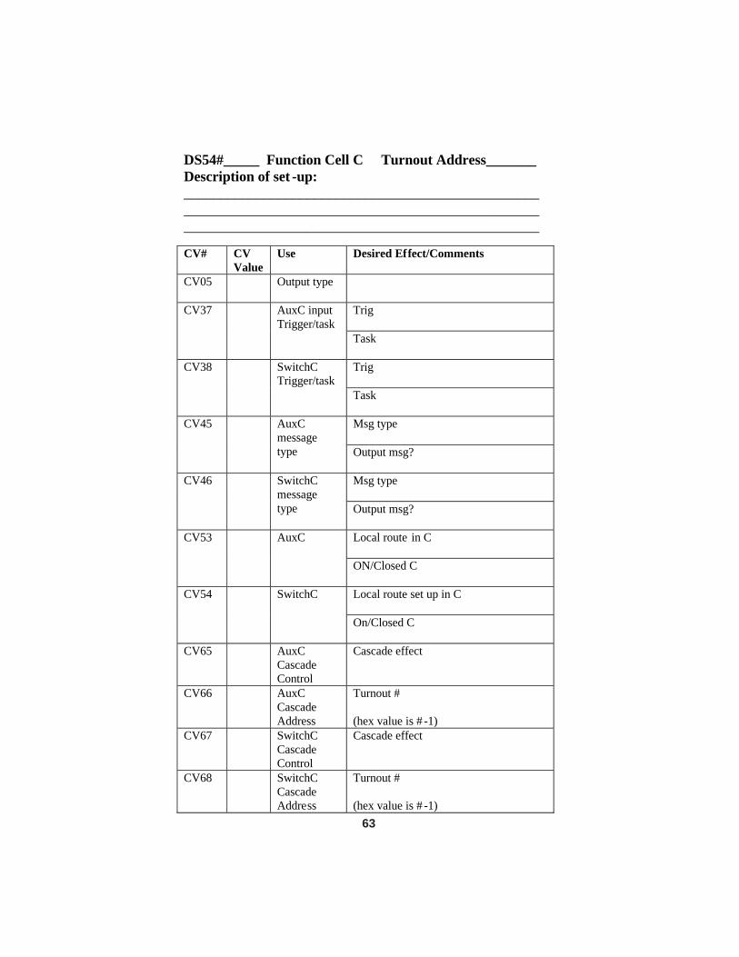
63
DS54#_____ Function Cell C Turnout Address_______ Description of set -up: ___________________________________________________________________________________________________________________________________________________ CV# CV
Value Use Desired Effect/Comments
CV05
Output type
Trig
CV37 AuxC input Trigger/task
Task Trig
CV38 SwitchC Trigger/task
Task Msg type
CV45 AuxC message type Output msg?
Msg type
CV46 SwitchC message type Output msg?
Local route in C
CV53 AuxC
ON/Closed C Local route set up in C
CV54 SwitchC
On/Closed C
CV65 AuxC Cascade Control
Cascade effect
CV66 AuxC Cascade Address
Turnout # (hex value is # -1)
CV67 SwitchC Cascade Control
Cascade effect
CV68 SwitchC Cascade Address
Turnout # (hex value is # -1)
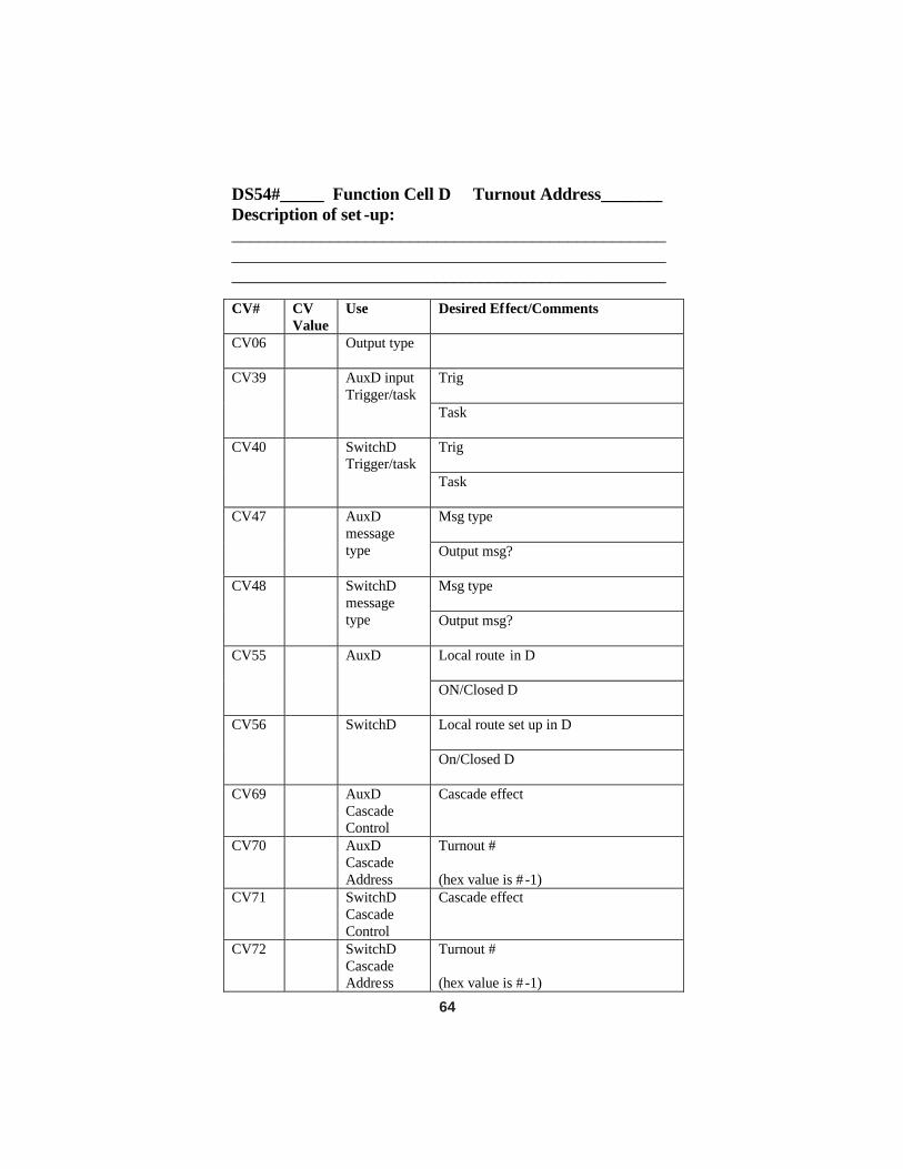
64
DS54#_____ Function Cell D Turnout Address_______ Description of set -up: ___________________________________________________________________________________________________________________________________________________ CV# CV
Value Use Desired Effect/Comments
CV06
Output type
Trig
CV39 AuxD input Trigger/task
Task Trig
CV40 SwitchD Trigger/task
Task Msg type
CV47 AuxD message type Output msg?
Msg type
CV48 SwitchD message type Output msg?
Local route in D
CV55 AuxD
ON/Closed D Local route set up in D
CV56 SwitchD
On/Closed D
CV69 AuxD Cascade Control
Cascade effect
CV70 AuxD Cascade Address
Turnout # (hex value is # -1)
CV71 SwitchD Cascade Control
Cascade effect
CV72 SwitchD Cascade Address
Turnout # (hex value is # -1)
17.0 Warranty and Repair InformationDS54
One year guarantee on DS54. See www.digitrax.com for current war-ranty policies and procedures. These units are not user serviceable. If adefect occurs, return the unit to Digitrax for service. Digitrax will repair orreplace DS54s at our discretion at no charge to you for one year from pur-chase date. This warranty excludes damage due to abuse, such as failure toproperly protect against input over current with a fuse or circuit breaker orapplying excessive input voltage to the unit. We will make any repairneeded because of physical damage or electrical abuse at fair and reason-able rates.
All warranties on Digitrax products are limited to refund of purchaseprice or repair or replacement of Digitrax products at the sole discretion ofDigitrax. In the event that Digitrax products are not installed or used inaccordance with the manufacturer's specifications, any and all warrantieseither expressed or implied are void. Except to the extent expressly statedin this section, there are no warranties, express or implied, including butnot limited to any warranties of merchantability or fitness for a particularpurpose.
Digitrax, Inc. reserves the right to make changes in design and specifi-cations and/or to make additions or improvements in its products withoutimposing any obligations upon itself to install these changes, additions orimprovements on products previously manufactured.
FCC InformationRadio or TV Interference: (this information is MANDATED by the FCC)
This equipment has been tested and found to comply with the limits for a Class B digital device,pursuant to part 15 of the FCC rules. These limits are designed to provide reasonable protectionagainst harmful interference when the equipment is operated in a residential environment. Thisequipment generates, uses and can radiate radio frequency energy and, if not installed and used inaccordance with the instruction manual, may cause harmful interference to radio communications.However, there is no guarantee that interference will not occur in a particular installation. If thisequipment does cause harmful interference to radio or television reception, which can be deter-mined by turning the equipment off and on, the user is encouraged to try to correct the interferenceby one or more of the following measures:
-Reorient or relocate the receiving antenna.-Increase the separation between the equipment and the receiver.-Connect the equipment into an outlet on a circuit different form that to which the
receiver is connected.-Consult the dealer or an experienced radio/TV technician for help.
Note that any modifications to the equipment not expressly approved by Digitrax voids the user'sauthority to operate under and be in compliance with CFR 47 rules, as administered by theFederal Communication Commission. Digitrax believes any conscientiously installed equip-ment following guidelines in this manual would be unlikely to experience RFI problems.
65