document insertion unit-h1 service...
TRANSCRIPT
654321
Document Insertion Unit-H1
Service Manual
August 3, 2009Revision 0

0
0�
�
ApplicationThis manual has been issued by Canon Inc. for qualified persons to learn technical theory, installation, maintenance, and repair of products. This manual covers all localities where the products are sold. For this reason, there may be information in this manual that does not apply to your locality.
CorrectionsThis manual may contain technical inaccuracies or typographical errors due to improvements
or changes in products. When changes occur in applica�le products or in the contents of this manual, Canon will release technical information as the need arises. In the event of major changes in the contents of this manual over a long or short period, Canon will issue a new edition of this manual.
The following paragraph does not apply to any countries where such provisions are inconsistent with local law.
TrademarksThe product names and company names used in this manual are the registered trademarks of the individual companies.
CopyrightThis manual is copyrighted with all rights reserved. Under the copyright laws, this manual may not be copied, reproduced or translated into another language, in whole or in part, without the written consent of Canon Inc.
(C) CANON INC. 2007
CautionUse of this manual should �e strictly supervised to avoid disclosure of confidential information.
0
0c
c
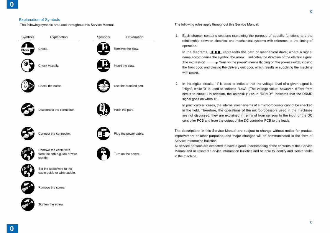
Explanation of Sym�olsThe following symbols are used throughout this Service Manual.
Sym�ols Explanation Sym�ols Explanation
Check. Remove the claw.
Check visually. Insert the claw.
Check the noise. Use the �undled part.
Disconnect the connector. Push the part.
Connect the connector. Plug the power cable.
Remove the cable/wire from the cable guide or wire saddle.
Turn on the power.
Set the cable/wire to the cable guide or wire saddle.
Remove the screw.
Tighten the screw.
The following rules apply throughout this Service Manual:
1. Each chapter contains sections explaining the purpose of specific functions and the relationship between electrical and mechanical systems with reference to the timing of operation.
In the diagrams, represents the path of mechanical drive; where a signal name accompanies the symbol, the arrow indicates the direction of the electric signal. The expression "turn on the power" means flipping on the power switch, closing the front door, and closing the delivery unit door, which results in supplying the machine with power.
2. In the digital circuits, '1' is used to indicate that the voltage level of a given signal is "High", while '0' is used to indicate "Low". (The voltage value, however, differs from circuit to circuit.) In addition, the asterisk (*) as in "DRMD*" indicates that the DRMD signal goes on when '0'.
In practically all cases, the internal mechanisms of a microprocessor cannot be checked in the field. Therefore, the operations of the microprocessors used in the machines are not discussed: they are explained in terms of from sensors to the input of the DC controller PCB and from the output of the DC controller PCB to the loads.
The descriptions in this Service Manual are subject to change without notice for product improvement or other purposes, and major changes will be communicated in the form of Service Information �ulletins.All service persons are expected to have a good understanding of the contents of this Service Manual and all relevant Service Information �ulletins and �e a�le to identify and isolate faults in the machine.

0
0d
d
0
0e
e
Contents Safety Precautions 0-1
Points to Note About Turning Off the Main Power Switch ----------0-2Notes Before it Works Serving ---------------------------------------------0-3
1 Product Outline 1-1Features -------------------------------------------------------------------------1-2Specifications ------------------------------------------------------------------1-3Names of Parts ----------------------------------------------------------------1-4
External View(Front) -------------------------------------------------------------- 1-4External View(Rear) --------------------------------------------------------------- 1-4External View(Internal) ----------------------------------------------------------- 1-5
2 Technology 2-1Basic Configuration -----------------------------------------------------------2-2
Functional Configuration --------------------------------------------------------- 2-2Overview of Electrical Circuitry ------------------------------------------------- 2-2Component Configuration ------------------------------------------------------- 2-3Drive Configuration ---------------------------------------------------------------- 2-4Basic movement outline ---------------------------------------------------------- 2-4
Various Modes of Control ---------------------------------------------------2-6Outline of operations -------------------------------------------------------------- 2-6Jam Detection ---------------------------------------------------------------------2-15Power Supply ----------------------------------------------------------------------2-17Work of service --------------------------------------------------------------------2-19
3 Periodic Servicing 3-1List of Work for Scheduled Servicing ------------------------------------3-2
4 Parts Replacement/Cleaning Procedure 4-1List Of Parts --------------------------------------------------------------------4-2
External / Internal Covers -------------------------------------------------------- 4-2Consuma�le Parts Requiring Periodic Replacement and Cleaning Points --------------------------------------------------------------------------------- 4-3Motors/PCBs/Others -------------------------------------------------------------- 4-4List of Sensors ---------------------------------------------------------------------- 4-5
External/Innernal Covers ----------------------------------------------------4-6Removing the Rear Upper Cover ---------------------------------------------- 4-6Removing the Rear Lower Cover ---------------------------------------------- 4-7Removing the Front Upper Cover --------------------------------------------- 4-7Removing the Front Inner Cover ----------------------------------------------- 4-8Removing the Inserter Rear Cover -------------------------------------------- 4-9Changing the Inserter Top Cover Open/Close Angle --------------------- 4-9Removing the Inserter Front Cover ------------------------------------------4-10Changing the Middle Guide Open/Close Angle ---------------------------4-10Changing the Inserter Open Angle ------------------------------------------- 4-11
Removing the Main Unit --------------------------------------------------- 4-12Removing the Upper Tray Unit ------------------------------------------------4-12Removing the Lower Tray Unit ------------------------------------------------4-13Removing the Inserter Pickup Unit -------------------------------------------4-13
Consuma�le Parts Requiring Periodic Replacement and Cleaning Points -------------------------------------------------------------------------- 4-15
Removing the Inserter pickup rollers (upper) ------------------------------4-15Removing the Inserter pickup roller (lower) --------------------------------4-16Removing the Inserter separation roller (upper) --------------------------4-16Removing the Inserter separation roller (lower) ---------------------------4-17Removing the Inserter feed roller (upper) ----------------------------------4-17Removing the Inserter feed roller (lower) -----------------------------------4-18Removing the Inserter torque limiter (upper) ------------------------------4-18Removing the Inserter torque limiter (lower) -------------------------------4-19Removing the Inserter electromagnetic clutch (upper) ------------------4-19Removing the Inserter electromagnetic clutch (lower) ------------------4-20
Removing the Motor -------------------------------------------------------- 4-21Removing the Tray Pickup Motor (M1) --------------------------------------4-21Removing the Drive Switchover Motor (M4) -------------------------------4-22Removing the Upper Tray Lift Motor (M2) ----------------------------------4-23Removing the Lower Tray Lift Motor (M3) ----------------------------------4-23
0
0f
f
Removing the PCB --------------------------------------------------------- 4-24Removing the DC Controller PCB -------------------------------------------4-24Removing the Upper Tray LED PCB -----------------------------------------4-25Removing the Lower Tray LED PCB -----------------------------------------4-25
Removing the Sensor ------------------------------------------------------ 4-27Removing the Upper tray empty sensor (S9) -----------------------------4-27Removing the Upper tray width sensor (S10) -----------------------------4-28Removing the Upper tray last paper sensor (S11) -----------------------4-29Removing the Low tray empty sensor (S12) -------------------------------4-29Removing the Low tray width sensor (S13) --------------------------------4-30Removing the Low tray last paper sensor 1 (S14) -----------------------4-31Removing the Low tray last paper sensor 2 (S15) -----------------------4-32
5 Adjustment 5-1Adjustment at Time of Parts Replacement -----------------------------5-2
6 Installation 6-1Making Pre-installation Checks --------------------------------------------6-2
Checking the Power Supply ----------------------------------------------------- 6-2Checking the Installation Space ------------------------------------------------ 6-2Cautions at the Time of Installation -------------------------------------------- 6-3
Checking Bundled Components -------------------------------------------6-4Unpacking -----------------------------------------------------------------------6-5
Unpacking Procedure ------------------------------------------------------------- 6-5Installation Procedure --------------------------------------------------------6-7
Preparation for Installation on Upstream Connection Machine Side - 6-7Connecting to Connection Machine ------------------------------------------- 6-8Height/Inclination Checks -------------------------------------------------------6-10Connecting the Ca�les ----------------------------------------------------------6-13Connecting the Wire saddle ----------------------------------------------------6-14Making Checks after Completion of Installation Work -------------------6-15Operation Checks -----------------------------------------------------------------6-15
7 Appendix 7-1Service Tools -------------------------------------------------------------------7-2
General Circuit Diagram -----------------------------------------------------7-3General Circuit Diagram --------------------------------------------------------- 7-3
Safety PrecautionsPoints to Note A�out Turn ing Off the Main Power SwitchNotes Before it Works Serving
■
■

0
00-2
0-2
Points to Note About Turning Off the Main Power Switch
Points to Note About Turning Off the Main Power Switch
Points to Note About Turning Off the Main Power SwitchThis machine has two switches related to power supply, the Power switch and the breaker.Turning on the Power switch powers this machine.The �reaker detects an excess current and electric leakage to protect you against an electric shock.
MEMO:Explain to the customer that the breaker must be checked once or twice a month and the result must �e recorded.

0
00-3
0-3
Points to Note About Turning Off the Main Power Switch
Points to Note About Turning Off the Main Power Switch
Notes Before it Works Serving
CAUTION:
At servicing, be sure to turn off the power source according to the specified steps and disconnect the power plug.
CAUTION:
Do not turn off the power switch when downloading is under way.
Turning off the main power switch while downloading is under way can disable the machine.
1
1 Product Outline
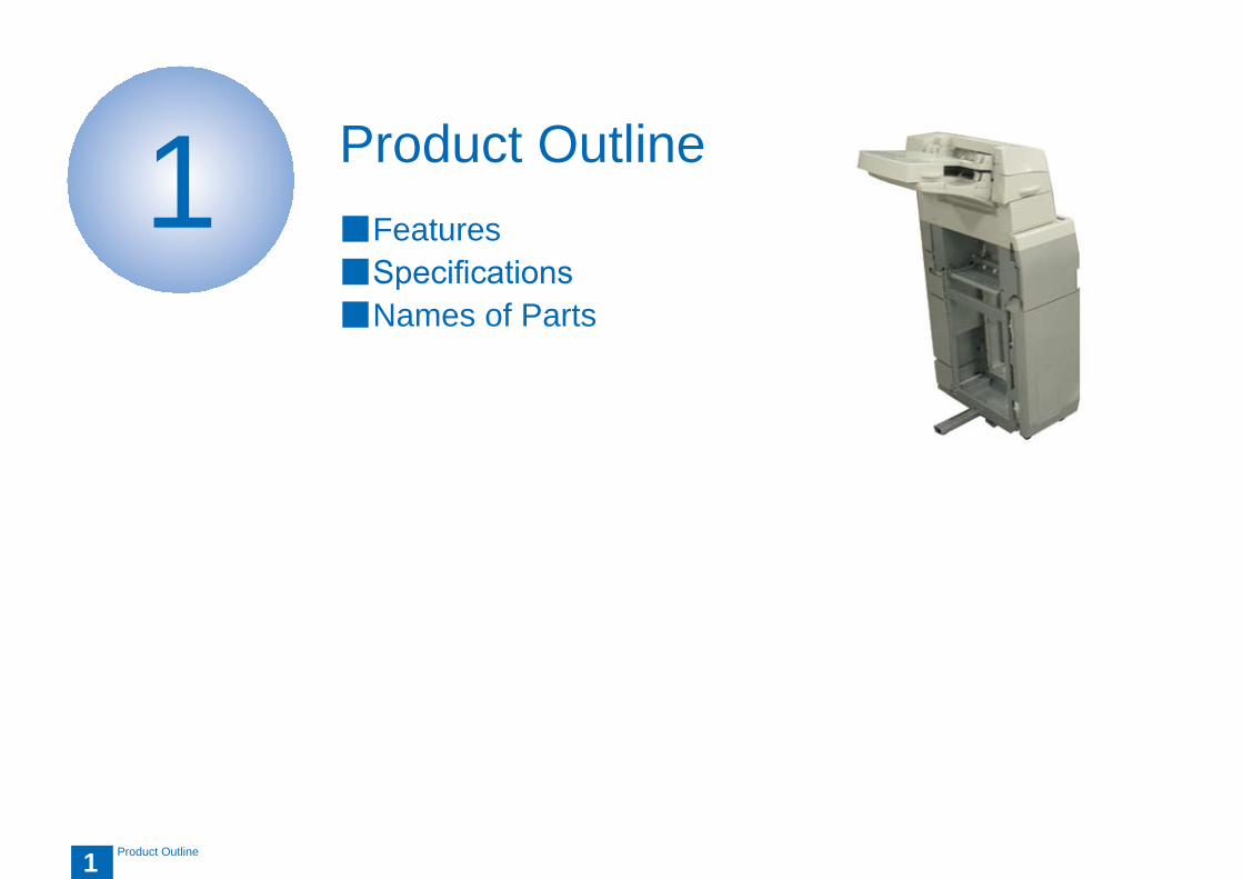
Product OutlineFeaturesSpecificationsNames of Parts
■■■

1
11-2
1-2
Product Outline > Features
Product Outline > Features
Features
A free-standing inserter with a reversal feature, supporting a set of two large tray bins.Each tray has a capacity of 200 sheets.
●
●
1
11-3
1-3
Product Outline > Specifications
Product Outline > Specifications
Specifications
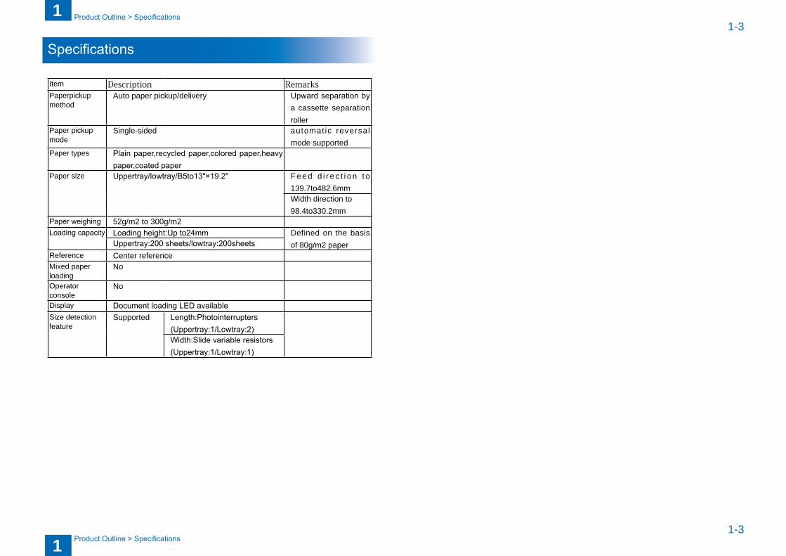
Item Description RemarksPaperpickup method
Auto paper pickup/delivery Upward separation by a cassette separation roller
Paper pickup mode
Single-sided automat ic reversal mode supported
Paper types Plain paper,recycled paper,colored paper,heavy paper,coated paper
Paper size Uppertray/lowtray/B5to13"×19.2" F e e d d i r e c t i o n t o 139.7to482.6mmWidth direction to 98.4to330.2mm
Paper weighing 52g/m2 to 300g/m2Loading capacity Loading height:Up to24mm Defined on the �asis
of 80g/m2 paperUppertray:200 sheets/lowtray:200sheetsReference Center referenceMixed paper loading
No
Operator console
No
Display Document loading LED availableSize detection feature
Supported Length:Photointerrupters(Uppertray:1/Lowtray:2)Width:Slide variable resistors(Uppertray:1/Lowtray:1)
1
11-4
1-4
Product Outline > Names of Parts > External View(Rear)
Product Outline > Names of Parts > External View(Rear)
Names of Parts
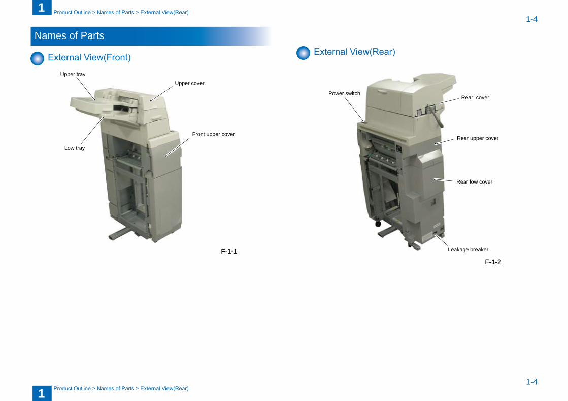
External View(Front)
Upper tray
Low tray
Upper cover
Front upper cover
F-1-1F-1-1
External View(Rear)
Power switch
Leakage breaker
Rear low cover
Rear upper cover
Rear cover
F-1-2F-1-2
1
11-5
1-5
Product Outline > Names of Parts > External View(Internal)
Product Outline > Names of Parts > External View(Internal)
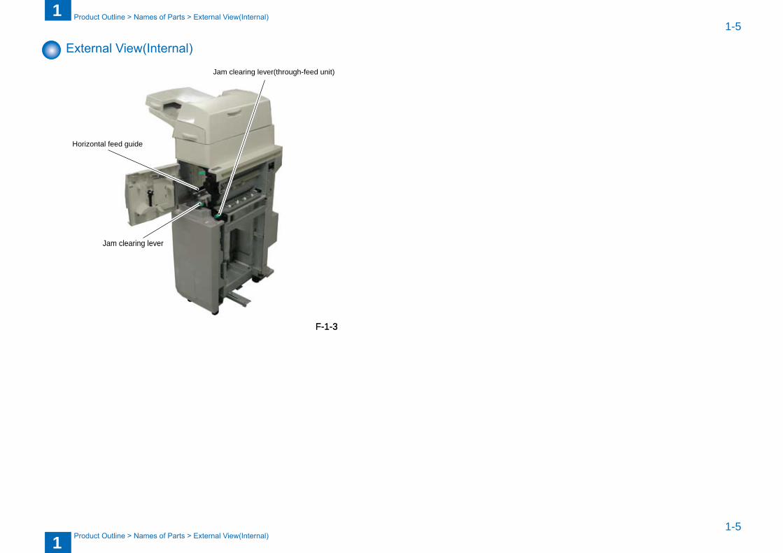
External View(Internal)
Horizontal feed guide
Jam clearing lever(through-feed unit)
Jam clearing lever
F-1-3F-1-3
2
2 Technology
TechnologyBasic ConfigurationControlsJam DetectionPower SupplyWork of service
■■■■■
2
22-2
2-2
Technology > Basic Configuration > Overview of Electrical Circuitry
Technology > Basic Configuration > Overview of Electrical Circuitry
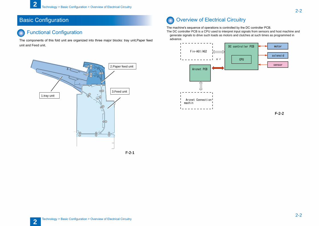
Basic Configuration
Functional ConfigurationThe components of this fold unit are organized into three major blocks: tray unit,Paper feed unit and Feed unit.
1.tray unit
2.Paper feed unit
3.Feed unit
F-2-1F-2-1
Overview of Electrical CircuitryThe machine's sequence of operations is controlled by the DC controller PCB.The DC controller PCB is a CPU used to interpret input signals from sensors and host machine and
generate signals to drive such loads as motors and clutches at such times as programmed in advance.
Fin-AG1/AG2
DC controller PCB motor
solenoid
sensor
CPU
Arcnet Connection machin
Arcnet PCB
or
F-2-2F-2-2
2
22-3
2-3
Technology > Basic Configuration > Component Configuration > Sensor Layout
Technology > Basic Configuration > Component Configuration > Sensor Layout
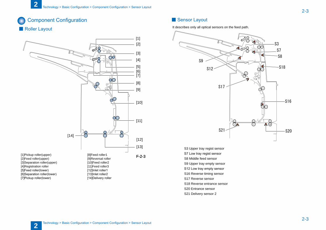
Component ConfigurationRoller Layout
[1]
[12]
[13]
[14]
[2]
[3]
[4]
[5][6][7]
[8]
[9]
[10]
[11]
[1]Pickup roller(upper) [8]Feed roller1 [2]Feed roller(upper) [9]Reversal roller [3]Separation roller(upper) [10]Feed roller2 [4]Registration roller [11]Feed roller3 [5]Feed roller(lower) [12]Inlet roller1 [6]Separation roller(lower) [13]Inlet roller2 [7]Pickup roller(lower) [14]Delivery roller
■
F-2-3F-2-3
Sensor LayoutIt descri�es only all optical sensors on the feed path.
S20S21
S3
S16
S17
S9
S12
S7
S8
S18
S3 Upper tray regist sensor S7 Low tray regist sensor S8 Middle feed sensor S9 Upper tray empty sensor S12 Low tray empty sensor S16 Reverse timing sensor S17 Reverse sensor S18 Reverse entrance sensor S20 Entrance sensor S21 Delivery sensor 2
■
2
22-4
2-4
Technology > Basic Configuration > Basic movement outline > Surface insert operation
Technology > Basic Configuration > Basic movement outline > Surface insert operation
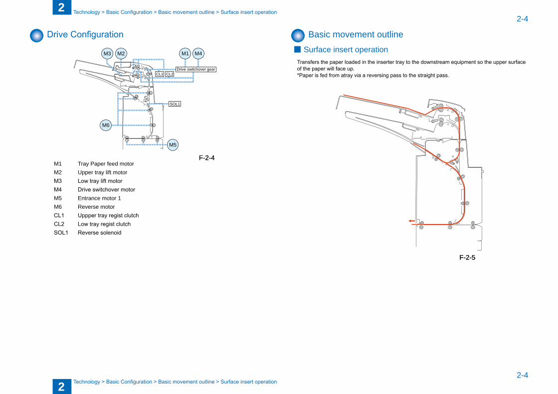
Drive Configuration
M1 M4
Drive switchover gearCL1 CL2
SOL1
M3 M2
M6
M5
M1 Tray Paper feed motor M2 Upper tray lift motor M3 Low tray lift motor M4 Drive switchover motor M5 Entrance motor 1 M6 Reverse motor CL1 Uppper tray regist clutch CL2 Low tray regist clutch SOL1 Reverse solenoid
F-2-4F-2-4
Basic movement outlineSurface insert operation
Transfers the paper loaded in the inserter tray to the downstream equipment so the upper surface of the paper will face up.
*Paper is fed from atray via a reversing pass to the straight pass.
■
F-2-5F-2-5
2
22-5
2-5
Technology > Basic Configuration > Basic movement outline > Insetrter pickup tray switch operation
Technology > Basic Configuration > Basic movement outline > Insetrter pickup tray switch operation
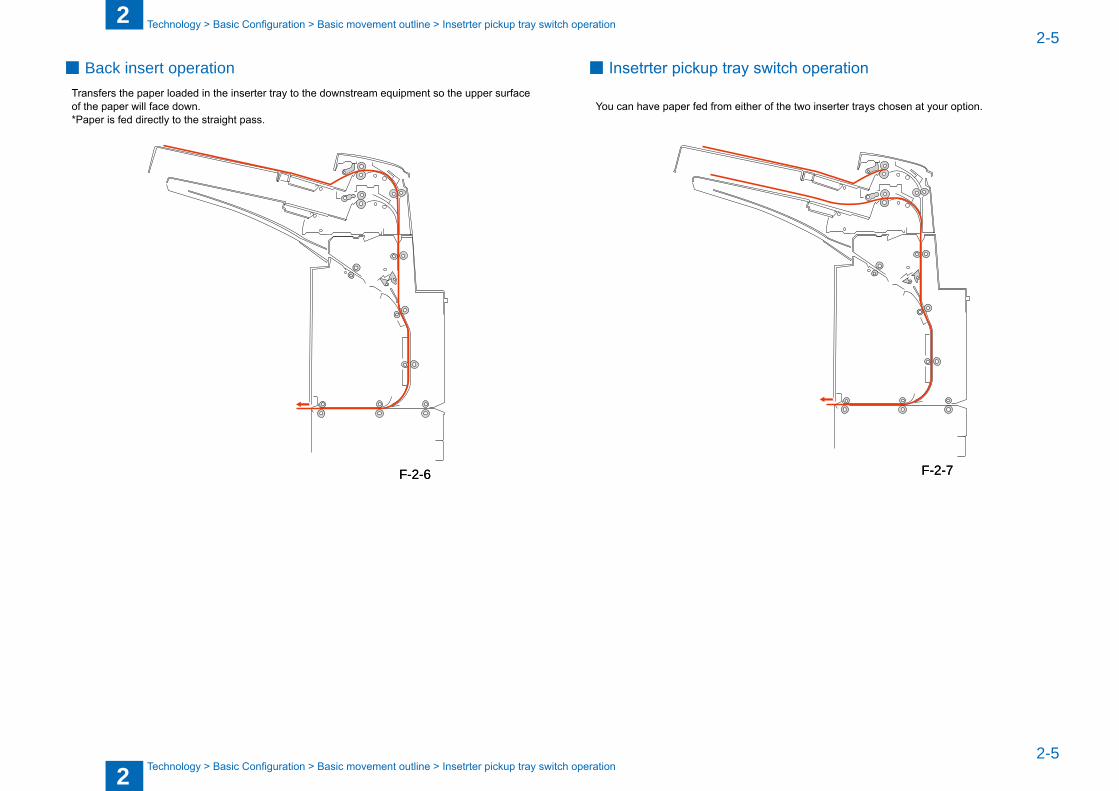
Back insert operation Transfers the paper loaded in the inserter tray to the downstream equipment so the upper surface
of the paper will face down. *Paper is fed directly to the straight pass.
■
F-2-6F-2-6
Insetrter pickup tray switch operation
You can have paper fed from either of the two inserter trays chosen at your option.
■
F-2-7F-2-7
2
22-6
2-6
Technology > Various Modes of Control > Outline of operations > Sequence of surface insert operation
Technology > Various Modes of Control > Outline of operations > Sequence of surface insert operation
Various Modes of Control
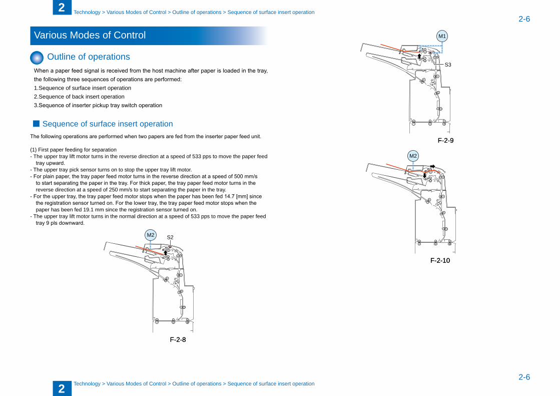
Outline of operationsWhen a paper feed signal is received from the host machine after paper is loaded in the tray, the following three sequences of operations are performed:1.Sequence of surface insert operation2.Sequence of �ack insert operation3.Sequence of inserter pickup tray switch operation
Sequence of surface insert operation The following operations are performed when two papers are fed from the inserter paper feed unit.
(1) First paper feeding for separation- The upper tray lift motor turns in the reverse direction at a speed of 533 pps to move the paper feed
tray upward.- The upper tray pick sensor turns on to stop the upper tray lift motor. - For plain paper, the tray paper feed motor turns in the reverse direction at a speed of 500 mm/s
to start separating the paper in the tray. For thick paper, the tray paper feed motor turns in the reverse direction at a speed of 250 mm/s to start separating the paper in the tray.
- For the upper tray, the tray paper feed motor stops when the paper has been fed 14.7 [mm] since the registration sensor turned on. For the lower tray, the tray paper feed motor stops when the paper has �een fed 19.1 mm since the registration sensor turned on.
- The upper tray lift motor turns in the normal direction at a speed of 533 pps to move the paper feed tray 9 pls downward.
S2M2
■
F-2-8F-2-8
S3
M1
M2
F-2-9F-2-9
F-2-10F-2-10
2
22-7
2-7
Technology > Various Modes of Control > Outline of operations > Sequence of surface insert operation
Technology > Various Modes of Control > Outline of operations > Sequence of surface insert operation
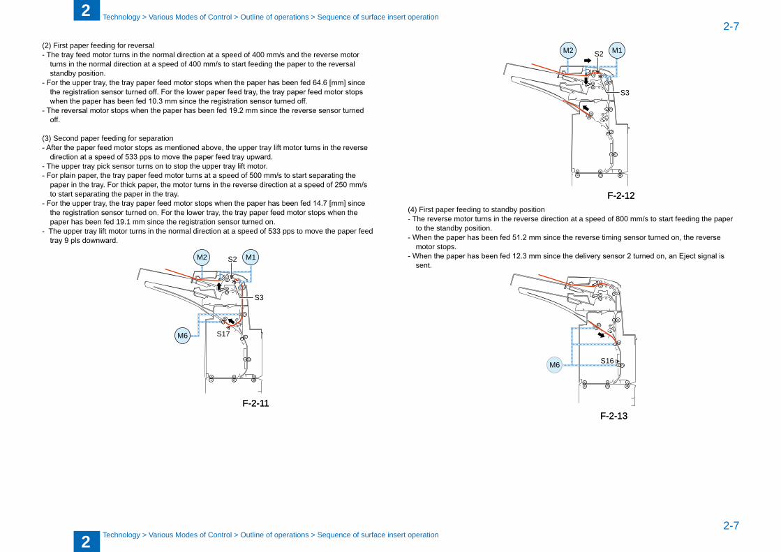
(2) First paper feeding for reversal - The tray feed motor turns in the normal direction at a speed of 400 mm/s and the reverse motor
turns in the normal direction at a speed of 400 mm/s to start feeding the paper to the reversal stand�y position.
- For the upper tray, the tray paper feed motor stops when the paper has been fed 64.6 [mm] since the registration sensor turned off. For the lower paper feed tray, the tray paper feed motor stops when the paper has been fed 10.3 mm since the registration sensor turned off.
- The reversal motor stops when the paper has been fed 19.2 mm since the reverse sensor turned off.
(3) Second paper feeding for separation- After the paper feed motor stops as mentioned above, the upper tray lift motor turns in the reverse
direction at a speed of 533 pps to move the paper feed tray upward.- The upper tray pick sensor turns on to stop the upper tray lift motor.- For plain paper, the tray paper feed motor turns at a speed of 500 mm/s to start separating the
paper in the tray. For thick paper, the motor turns in the reverse direction at a speed of 250 mm/s to start separating the paper in the tray.
- For the upper tray, the tray paper feed motor stops when the paper has been fed 14.7 [mm] since the registration sensor turned on. For the lower tray, the tray paper feed motor stops when the paper has �een fed 19.1 mm since the registration sensor turned on.
- The upper tray lift motor turns in the normal direction at a speed of 533 pps to move the paper feed tray 9 pls downward.
S3
S17
S2
M6
M2 M1
F-2-11F-2-11
M2
S3
S2 M1
(4) First paper feeding to stand�y position - The reverse motor turns in the reverse direction at a speed of 800 mm/s to start feeding the paper
to the stand�y position.- When the paper has been fed 51.2 mm since the reverse timing sensor turned on, the reverse
motor stops.- When the paper has been fed 12.3 mm since the delivery sensor 2 turned on, an Eject signal is
sent.
M6 S16
F-2-12F-2-12
F-2-13F-2-13
2
22-8
2-8
Technology > Various Modes of Control > Outline of operations > Sequence of surface insert operation
Technology > Various Modes of Control > Outline of operations > Sequence of surface insert operation
M6 S16
S21
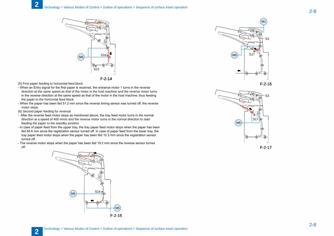
(5) First paper feeding to horizontal feed �lock- When an Entry signal for the first paper is received, the entrance motor 1 turns in the reverse
direction at the same speed as that of the motor in the host machine and the reverse motor turns in the reverse direction at the same speed as that of the motor in the host machine, thus feeding the paper to the horizontal feed �lock.
- When the paper has been fed 51.2 mm since the reverse timing sensor was turned off, the reverse motor stops.
(6) Second paper feeding for reversal- After the reverse feed motor stops as mentioned above, the tray feed motor turns in the normal
direction at a speed of 400 mm/s and the reverse motor turns in the normal direction to start feeding the paper to the stand�y position.
- In case of paper feed from the upper tray, the tray paper feed motor stops when the paper has been fed 64.6 mm since the registration sensor turned off. In case of paper feed from the lower tray, the tray paper feed motor stops when the paper has been fed 10.3 mm since the registration sensor turned off.
- The reverse motor stops when the paper has been fed 19.2 mm since the reverse sensor turned off.
M6 S16
M5
F-2-14F-2-14
F-2-15F-2-15
S3
S17M6
M1
S3
S17M6
F-2-16F-2-16
F-2-17F-2-17
2
22-9
2-9
Technology > Various Modes of Control > Outline of operations > Sequence of surface insert operation
Technology > Various Modes of Control > Outline of operations > Sequence of surface insert operation
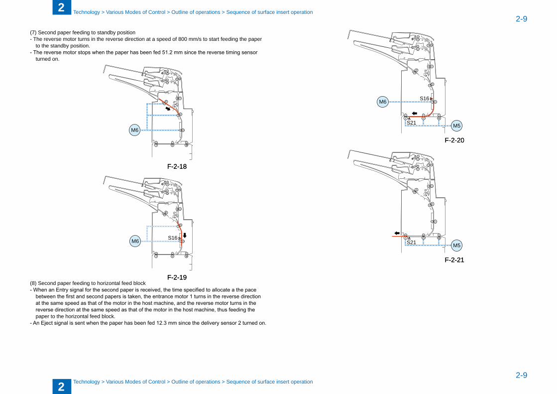
(7) Second paper feeding to stand�y position- The reverse motor turns in the reverse direction at a speed of 800 mm/s to start feeding the paper
to the stand�y position.- The reverse motor stops when the paper has been fed 51.2 mm since the reverse timing sensor
turned on.
M6
M6 S16
(8) Second paper feeding to horizontal feed �lock- When an Entry signal for the second paper is received, the time specified to allocate a the pace
between the first and second papers is taken, the entrance motor 1 turns in the reverse direction at the same speed as that of the motor in the host machine, and the reverse motor turns in the reverse direction at the same speed as that of the motor in the host machine, thus feeding the paper to the horizontal feed �lock.
- An Eject signal is sent when the paper has been fed 12.3 mm since the delivery sensor 2 turned on.
F-2-18F-2-18
F-2-19F-2-19
M6 S16
M5S21
M5S21
F-2-20F-2-20
F-2-21F-2-21
2
22-10
2-10
Technology > Various Modes of Control > Outline of operations > Sequence of �ack insert operation
Technology > Various Modes of Control > Outline of operations > Sequence of �ack insert operation
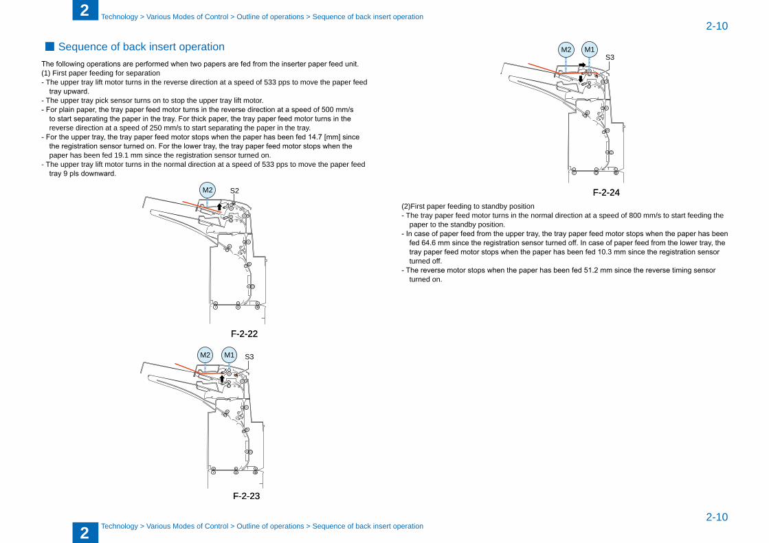
Sequence of �ack insert operationThe following operations are performed when two papers are fed from the inserter paper feed unit.(1) First paper feeding for separation- The upper tray lift motor turns in the reverse direction at a speed of 533 pps to move the paper feed
tray upward.- The upper tray pick sensor turns on to stop the upper tray lift motor. - For plain paper, the tray paper feed motor turns in the reverse direction at a speed of 500 mm/s
to start separating the paper in the tray. For thick paper, the tray paper feed motor turns in the reverse direction at a speed of 250 mm/s to start separating the paper in the tray.
- For the upper tray, the tray paper feed motor stops when the paper has been fed 14.7 [mm] since the registration sensor turned on. For the lower tray, the tray paper feed motor stops when the paper has �een fed 19.1 mm since the registration sensor turned on.
- The upper tray lift motor turns in the normal direction at a speed of 533 pps to move the paper feed tray 9 pls downward.
S2M2
S3M2 M1
■
F-2-22F-2-22
F-2-23F-2-23
M2S3
M1
(2)First paper feeding to stand�y position- The tray paper feed motor turns in the normal direction at a speed of 800 mm/s to start feeding the
paper to the stand�y position.- In case of paper feed from the upper tray, the tray paper feed motor stops when the paper has been
fed 64.6 mm since the registration sensor turned off. In case of paper feed from the lower tray, the tray paper feed motor stops when the paper has been fed 10.3 mm since the registration sensor turned off.
- The reverse motor stops when the paper has been fed 51.2 mm since the reverse timing sensor turned on.
F-2-24F-2-24
2
22-11
2-11
Technology > Various Modes of Control > Outline of operations > Sequence of �ack insert operation
Technology > Various Modes of Control > Outline of operations > Sequence of �ack insert operation
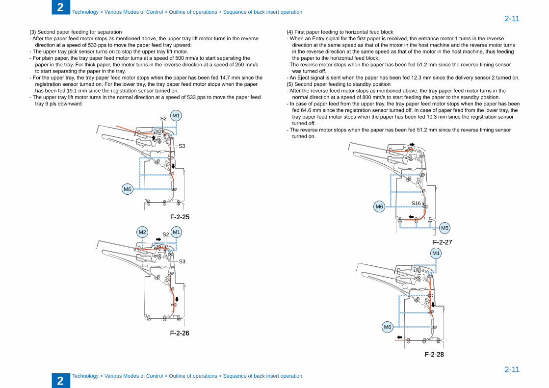
(3) Second paper feeding for separation- After the paper feed motor stops as mentioned above, the upper tray lift motor turns in the reverse
direction at a speed of 533 pps to move the paper feed tray upward.- The upper tray pick sensor turns on to stop the upper tray lift motor.- For plain paper, the tray paper feed motor turns at a speed of 500 mm/s to start separating the
paper in the tray. For thick paper, the motor turns in the reverse direction at a speed of 250 mm/s to start separating the paper in the tray.
- For the upper tray, the tray paper feed motor stops when the paper has been fed 14.7 mm since the registration sensor turned on. For the lower tray, the tray paper feed motor stops when the paper has �een fed 19.1 mm since the registration sensor turned on.
- The upper tray lift motor turns in the normal direction at a speed of 533 pps to move the paper feed tray 9 pls downward.
S2
S3
M6
M1
S2
S3
M2 M1
F-2-25F-2-25
F-2-26F-2-26
(4) First paper feeding to horizontal feed �lock- When an Entry signal for the first paper is received, the entrance motor 1 turns in the reverse
direction at the same speed as that of the motor in the host machine and the reverse motor turns in the reverse direction at the same speed as that of the motor in the host machine, thus feeding the paper to the horizontal feed �lock.
- The reverse motor stops when the paper has been fed 51.2 mm since the reverse timing sensor was turned off.
- An Eject signal is sent when the paper has been fed 12.3 mm since the delivery sensor 2 turned on.(5) Second paper feeding to stand�y position- After the reverse feed motor stops as mentioned above, the tray paper feed motor turns in the
normal direction at a speed of 800 mm/s to start feeding the paper to the stand�y position.- In case of paper feed from the upper tray, the tray paper feed motor stops when the paper has been
fed 64.6 mm since the registration sensor turned off. In case of paper feed from the lower tray, the tray paper feed motor stops when the paper has been fed 10.3 mm since the registration sensor turned off.
- The reverse motor stops when the paper has been fed 51.2 mm since the reverse timing sensor turned on.
S16M6
M5
M6
M1
F-2-27F-2-27
F-2-28F-2-28
2
22-12
2-12
Technology > Various Modes of Control > Outline of operations > Sequence of inserter pickup tray switch operation
Technology > Various Modes of Control > Outline of operations > Sequence of inserter pickup tray switch operation
M6
M1
S16
S3
(6) Second paper feeding to horizontal feed �lock- When an Entry signal for the second paper is received, the time specified to allocate a the pace
between the first and second papers is taken, the entrance motor 1 turns in the reverse direction at the same speed as that of the motor in the host machine, and the reverse motor turns in the reverse direction at the same speed as that of the motor in the host machine, thus feeding the paper to the horizontal feed �lock.
- The reverse motor stops when the paper has been fed 51.2 mm since the reverse timing sensor was turned off.
- An Eject signal is sent when the paper has been fed 12.3 mm since the delivery sensor 2 turned on.
S21
M6
M5
F-2-29F-2-29
F-2-30F-2-30
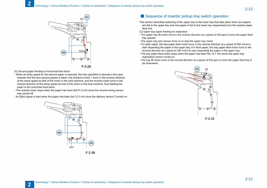
Sequence of inserter pickup tray switch operationThis section describes switching of the upper tray to the lower tray that take place when two papers
are fed to the upper tray and one paper is fed to the lower tray respectively from the inserter paper feed unit.
(1) Upper tray paper feeding for separation- The upper tray lift motor turns in the reverse direction at a speed of 533 pps to move the paper feed
tray upward.- The upper tray pick sensor turns on to stop the upper tray motor.- For plain paper, the tray paper feed motor turns in the reverse direction at a speed of 500 mm/s to
start separating the paper in the upper tray. For thick paper, the tray paper feed motor turns in the reverse direction at a speed of 250 mm/s to start separating the paper in the upper tray.
- The tray paper feed motor stops when the paper has been fed 14.7 mm since the upper tray registration sensor turned on.
- The tray lift motor turns in the normal direction at a speed of 533 pps to move the paper feed tray 9 pls downward.
S2M2
■
F-2-31F-2-31
2
22-13
2-13
Technology > Various Modes of Control > Outline of operations > Sequence of inserter pickup tray switch operation
Technology > Various Modes of Control > Outline of operations > Sequence of inserter pickup tray switch operation
S2 M1
M1M2
S3
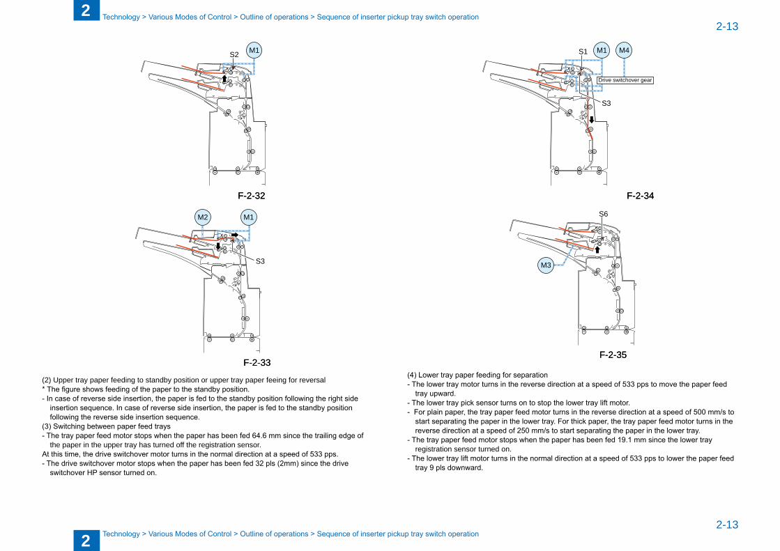
(2) Upper tray paper feeding to stand�y position or upper tray paper feeing for reversal* The figure shows feeding of the paper to the standby position.- In case of reverse side insertion, the paper is fed to the standby position following the right side
insertion sequence. In case of reverse side insertion, the paper is fed to the standby position following the reverse side insertion sequence.
(3) Switching between paper feed trays- The tray paper feed motor stops when the paper has been fed 64.6 mm since the trailing edge of
the paper in the upper tray has turned off the registration sensor. At this time, the drive switchover motor turns in the normal direction at a speed of 533 pps. - The drive switchover motor stops when the paper has been fed 32 pls (2mm) since the drive
switchover HP sensor turned on.
F-2-32F-2-32
F-2-33F-2-33
Drive switchover gear
M1 M4
S3
S1
S6
M3
(4) Lower tray paper feeding for separation- The lower tray motor turns in the reverse direction at a speed of 533 pps to move the paper feed
tray upward.- The lower tray pick sensor turns on to stop the lower tray lift motor.- For plain paper, the tray paper feed motor turns in the reverse direction at a speed of 500 mm/s to
start separating the paper in the lower tray. For thick paper, the tray paper feed motor turns in the reverse direction at a speed of 250 mm/s to start separating the paper in the lower tray.
- The tray paper feed motor stops when the paper has been fed 19.1 mm since the lower tray registration sensor turned on.
- The lower tray lift motor turns in the normal direction at a speed of 533 pps to lower the paper feed tray 9 pls downward.
F-2-34F-2-34
F-2-35F-2-35
2
22-14
2-14
Technology > Various Modes of Control > Outline of operations > Sequence of inserter pickup tray switch operation
Technology > Various Modes of Control > Outline of operations > Sequence of inserter pickup tray switch operation
S7 M1
M3
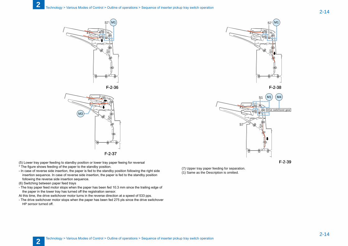
(5) Lower tray paper feeding to standby position or lower tray paper feeing for reversal* The figure shows feeding of the paper to the standby position.- In case of reverse side insertion, the paper is fed to the standby position following the right side
insertion sequence. In case of reverse side insertion, the paper is fed to the standby position following the reverse side insertion sequence.
(6) Switching between paper feed trays- The tray paper feed motor stops when the paper has been fed 10.3 mm since the trailing edge of
the paper in the lower tray has turned off the registration sensor. At this time, the drive switchover motor turns in the reverse direction at a speed of 533 pps.- The drive switchover motor stops when the paper has been fed 275 pls since the drive switchover
HP sensor turned off.
F-2-36F-2-36
F-2-37F-2-37
S7 M1
M1 M4
S7
S1
Drive switchover gear
(7) Upper tray paper feeding for separation. (1) Same as the Description is omitted.
F-2-38F-2-38
F-2-39F-2-39
2
22-15
2-15
Technology > Various Modes of Control > Jam Detection > Jam Type
Technology > Various Modes of Control > Jam Detection > Jam Type
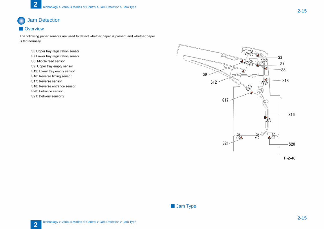
Jam DetectionOverview
The following paper sensors are used to detect whether paper is present and whether paper is fed normally.
S3 Upper tray registration sensor S7 Lower tray registration sensor S8: Middle feed sensor S9: Upper tray empty sensor S12: Lower tray empty sensor S16: Reverse timing sensor S17: Reverse sensor S18: Reverse entrance sensor S20: Entrance sensor S21: Delivery sensor 2
■
S20S21
S3
S16
S17
S9
S12
S7
S8
S18
Jam Type■
F-2-40F-2-40
2
22-16
2-16
Technology > Various Modes of Control > Jam Detection > Jam Type
Technology > Various Modes of Control > Jam Detection > Jam Type
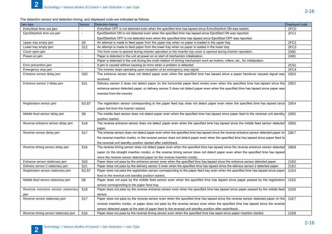
The detection sensor and detection timing, and displayed code are indicated as follows.Jam type Sensor Detection timing Displayed code
EntryStart time-out jam - EntryStart OFF is not detected even when the specified time has lapsed since EntryStartAck ON was replied. 2FC0EjectStartAck time-out jam - EjectStartAck ON is not detected even when the specified time has lapsed since EjectStart ON was reported.
EjectStartAck OFF is not detected even when the specified time has lapsed since EjectStart OFF was reported.2FC1
Upper tray empty jam S9 An attempt is made to feed paper from the upper tray when no paper is loaded in the upper tray. 2FC2Lower tray empty jam S12 An attempt is made to feed paper from the lower tray when no paper is loaded in the lower tray. 2FC3Cover open jam - The front cover is opened during inserter operation or the inserter top cover is opened during inserter operation. 2300Power-on jam - Paper is detected in the unit at power-on or start of mechanism initialization. 2400
- Paper is detected in the unit during the multi-rotation of driving mechanism such as motors, rollers, etc., for initialization.Error prevention jam - A jam is caused without causing an error when a problem is detected. 2C01Emergency stop jam - The inserter stops operating upon reception of an emergency stop signal. 2FC4Entrance sensor delay jam S20 The entrance sensor does not detect paper even when the specified time has lapsed since a paper handover request signal was
received. 20E0
Entrance sensor 2 delay jam S21 Delivery sensor 2 does not detect paper (in the horizontal paper feed mode) even when the specified time has lapsed since the entrance sensor detected paper, or delivery sensor 2 does not detect paper even when the specified time has lapsed since paper was inserted from the inserter.
20E2
Registration sensor jam S3,S7 The registration sensor corresponding to the paper feed tray does not detect paper even when the specified time has lapsed since paper fed from the inserter started.
20E4
Middle feed sensor delay jam S8 The middle feed sensor does not detect paper even when the specified time has lapsed since paper feed to the reversal unit standby position started.
20E5
Reverse entrance sensor delay jam S18 The reverse entrance sensor does not detect paper even when the specified time has lapsed since the middle feed sensor detected paper.
20E6
Reverse sensor delay jam S17 The reverse sensor does not detect paper even when the specified time has lapsed since the reverse entrance sensor detected paper (in the reverse insertion mode), or the reverse sensor does not detect paper even when the specified time has lapsed since paper feed to the reversal unit standby position started after switchback.
20E7
Reverse timing sensor delay jam S16 The reverse timing sensor does not detect paper even when the specified time has lapsed since the reverse entrance sensor detected paper (in the straight insertion mode), or the reverse timing sensor does not detect paper even when the specified time has lapsed since the reverse sensor detected paper (in the reverse insertion mode).
20E8
Entrance sensor stationary jam S20 Paper does not pass by the entrance sensor even when the specified time has lapsed since the entrance sensor detected paper. 21E0Delivery sensor 2 stationary jam S21 Paper does not pass by the delivery sensor 2 even when the specified time has lapsed since the delivery sensor 2 detected paper. 21E2Registration sensor stationary jam S3,S7 Paper does not pass the registration sensor corresponding to the paper feed tray even when the specified time has lapsed since paper
feed to the reversal unit stand�y position started.21E4
Middle feed sensor stationary jam S8 Paper does not pass by the middle feed sensor even when the specified time has lapsed since paper passed by the registration sensor corresponding to the paper feed tray.
21E5
Reverse entrance sensor stationary jam
S18 Paper does not pass by the reverse entrance sensor even when the specified time has lapsed since paper passed by the middle feed sensor.
21E6
Reverse sensor stationary jam S17 Paper does not pass by the reverse sensor even when the specified time has lapsed since the reverse sensor detected paper (in the reverse insertion mode), or paper does not pass by the reverse sensor even when the specified time has lapsed since the reverse sensor detected paper at the start of paper feed to the reversal unit standby position after switchback.
21E7
Reverse timing sensor stationary jam S16 Paper does not pass by the reverse timing sensor even when the specified time has lased since paper insertion started. 21E8

2
22-17
2-17
Technology > Various Modes of Control > Power Supply > Protection Function
Technology > Various Modes of Control > Power Supply > Protection Function
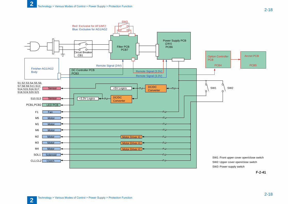
Power SupplyThe external AC power supplied to this machine passes through the filter PCB, and the filtered AC power is converted to 24 VDC. The 24 VDC is supplied to the DC control PCB from which it is supplied to the load-related parts (motors, solenoids, fans, and clutches) as it is or converted to 5 VDC or 3.3 VDC �y the DC-DC to �e supplied to logic-related parts (sensors).
Protection FunctionThe power supply PCB incorporates a primary-side, secondary-side overcurrent, and overvoltage protection circuits.
Each of load-related 24V lines has a fuse. If overcurrent or overvoltage occurs in a load (motor, etc.) due to a trouble such as a short circuit, the fuse blows to actuate the protection mechanism. Each of logic-related 5V/3.3V lines also has a fuse to actuate the protection mechanism.
■
2
22-18
2-18
Technology > Various Modes of Control > Power Supply > Protection Function
Technology > Various Modes of Control > Power Supply > Protection Function
Sensor
DC/DCConverter
+5V Logics
+3.3V Logics
Motor Driver IC
Motor Driver IC
Motor Driver IC
Circuit BreakerCB1
Filter PCBPCB7
Power Supply PCB(24V)PCB6
DC Controller PCBPCB3
LED PCB
Solenoid
Clutch
Motor
Motor
Motor
S1,S2,S3,S4,S5,S6,S7,S8,S9,S11,S12,S14,S15,S16,S17,S18,S19,S20,S21
M2
M3
M4
Motor
Motor
Motor
FanF1
M5
M1
M6
PCB1,PCB2
SOL1
CL1,CL2
SW1
Remote Signal (24V)
Remote Signal (3.3V)
Finisher-AG1/AG2Body
SW3Red: Exclusive for AF1/AF2
Remote Signal (3.3V)
Blue: Exclusive for AG1/AG2
SW2
SensorS10,S13
Option ControllerPCB
PCB4
SW1:Front upper cover open/close switchSW2:Upper cover open/close switchSW3:Power supply switch
Arcnet PCB
PCB5
DC/DCConverter
F-2-41F-2-41
2
22-19
2-19
Technology > Various Modes of Control > Work of service > Upgrading
Technology > Various Modes of Control > Work of service > Upgrading
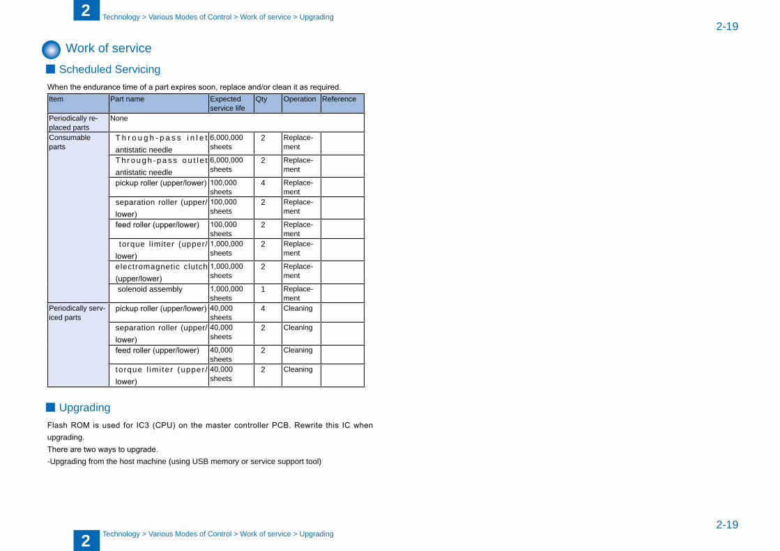
Work of serviceScheduled Servicing
When the endurance time of a part expires soon, replace and/or clean it as required.Item Part name Expected
service lifeQty Operation Reference
Periodically re-placed parts
None
Consuma�le parts
T h r o u g h - p a s s i n l e t antistatic needle
6,000,000 sheets
2 Replace-ment
T h r o u g h - p a s s o u t l e t antistatic needle
6,000,000 sheets
2 Replace-ment
pickup roller (upper/lower) 100,000 sheets
4 Replace-ment
separation roller (upper/lower)
100,000 sheets
2 Replace-ment
feed roller (upper/lower) 100,000 sheets
2 Replace-ment
torque l imiter (upper/lower)
1,000,000 sheets
2 Replace-ment
electromagnetic clutch (upper/lower)
1,000,000 sheets
2 Replace-ment
solenoid assem�ly 1,000,000 sheets
1 Replace-ment
Periodically serv-iced parts
pickup roller (upper/lower) 40,000 sheets
4 Cleaning
separation roller (upper/lower)
40,000 sheets
2 Cleaning
feed roller (upper/lower) 40,000 sheets
2 Cleaning
torque l imi ter (upper /lower)
40,000 sheets
2 Cleaning
UpgradingFlash ROM is used for IC3 (CPU) on the master controller PCB. Rewrite this IC when upgrading.There are two ways to upgrade.-Upgrading from the host machine (using USB memory or service support tool)
■
■

3
3 Periodic Servicing
P e r i o d i c Servicing
Periodic services items■
3
33-2
3-2
Periodic Servicing > List of Work for Scheduled Servicing
Periodic Servicing > List of Work for Scheduled Servicing
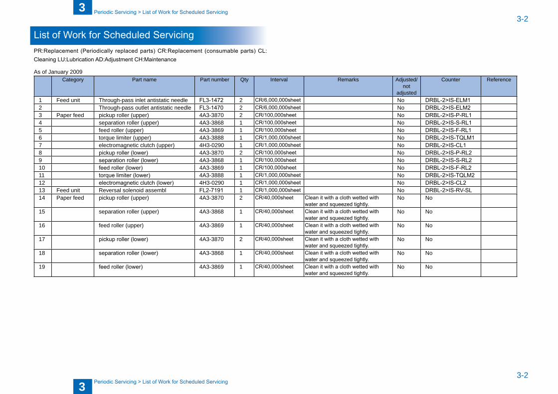
List of Work for Scheduled ServicingPR:Replacement (Periodically replaced parts) CR:Replacement (consumable parts) CL:Cleaning LU:Lubrication AD:Adjustment CH:Maintenance
As of January 2009№ Category Part name Part num�er Qty Interval Remarks Adjusted/
not adjusted
Counter Reference
1 Feed unit Through-pass inlet antistatic needle FL3-1472 2 CR/6,000,000sheet No DRBL-2>IS-ELM12 Through-pass outlet antistatic needle FL3-1470 2 CR/6,000,000sheet No DRBL-2>IS-ELM23 Paper feed pickup roller (upper) 4A3-3870 2 CR/100,000sheet No DRBL-2>IS-P-RL14 separation roller (upper) 4A3-3868 1 CR/100,000sheet No DRBL-2>IS-S-RL15 feed roller (upper) 4A3-3869 1 CR/100,000sheet No DRBL-2>IS-F-RL16 torque limiter (upper) 4A3-3888 1 CR/1,000,000sheet No DRBL-2>IS-TQLM17 electromagnetic clutch (upper) 4H3-0290 1 CR/1,000,000sheet No DRBL-2>IS-CL18 pickup roller (lower) 4A3-3870 2 CR/100,000sheet No DRBL-2>IS-P-RL29 separation roller (lower) 4A3-3868 1 CR/100,000sheet No DRBL-2>IS-S-RL210 feed roller (lower) 4A3-3869 1 CR/100,000sheet No DRBL-2>IS-F-RL211 torque limiter (lower) 4A3-3888 1 CR/1,000,000sheet No DRBL-2>IS-TQLM212 electromagnetic clutch (lower) 4H3-0290 1 CR/1,000,000sheet No DRBL-2>IS-CL213 Feed unit Reversal solenoid assem�l FL2-7191 1 CR/1,000,000sheet No DRBL-2>IS-RV-SL14 Paper feed pickup roller (upper) 4A3-3870 2 CR/40,000sheet Clean it with a cloth wetted with
water and squeezed tightly.No No
15 separation roller (upper) 4A3-3868 1 CR/40,000sheet Clean it with a cloth wetted with water and squeezed tightly.
No No
16 feed roller (upper) 4A3-3869 1 CR/40,000sheet Clean it with a cloth wetted with water and squeezed tightly.
No No
17 pickup roller (lower) 4A3-3870 2 CR/40,000sheet Clean it with a cloth wetted with water and squeezed tightly.
No No
18 separation roller (lower) 4A3-3868 1 CR/40,000sheet Clean it with a cloth wetted with water and squeezed tightly.
No No
19 feed roller (lower) 4A3-3869 1 CR/40,000sheet Clean it with a cloth wetted with water and squeezed tightly.
No No

4
4 Parts Replacement/Cleaning Procedure
P a r t s Rep lacemen t /C l e a n i n g Procedure
List of PartsExternal / Internal CoversMain UnitsC o n s u m a � l e P a r t s R e q u i r i n g P e r i o d i c R e p l a c e m e n t a n d Cleaning PointsMotors / PCBs Sensors
■■■■
■■
4
44-2
4-2
Parts Replacement/Cleaning Procedure > List Of Parts > External / Internal Covers
Parts Replacement/Cleaning Procedure > List Of Parts > External / Internal Covers
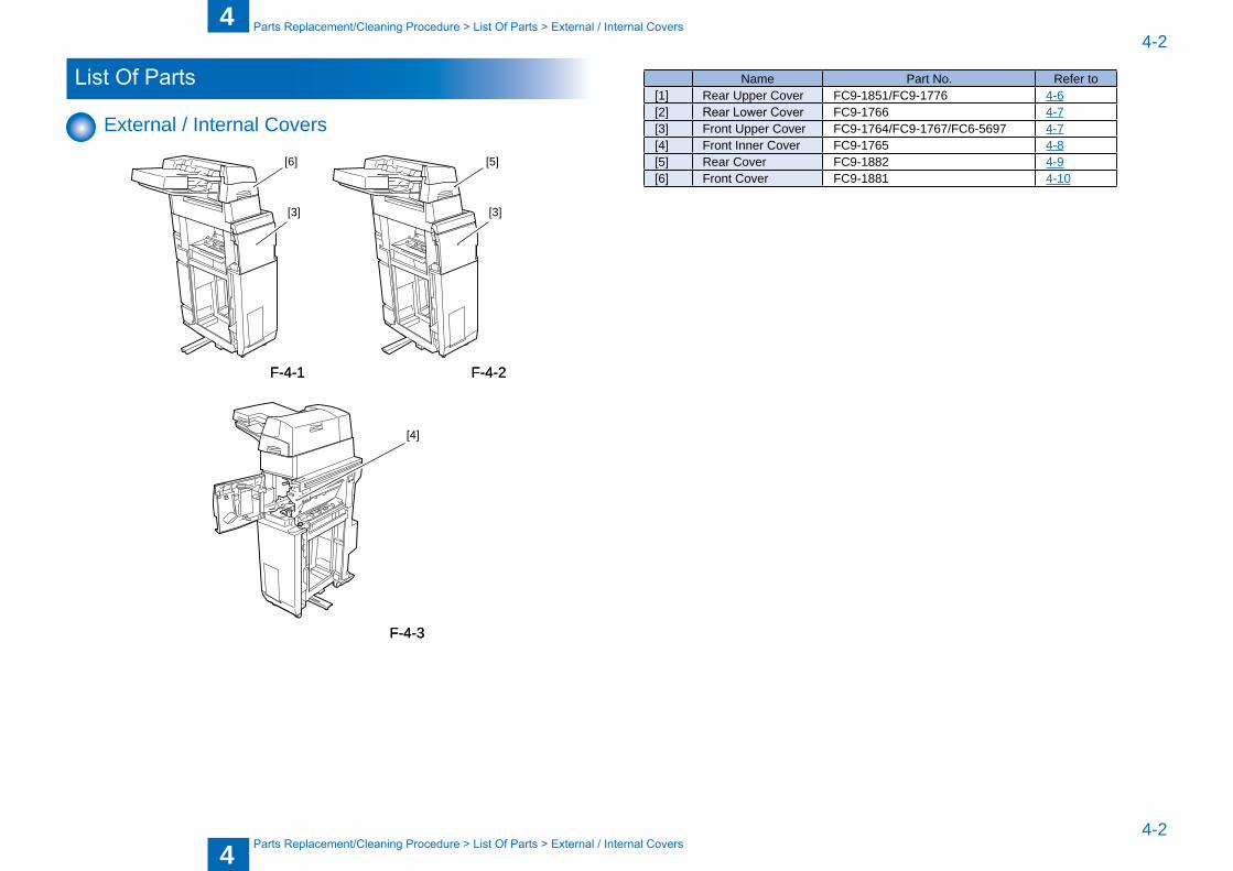
List Of Parts
External / Internal Covers
[6]
[3]
[5]
[3]
[4]
F-4-1F-4-1 F-4-2F-4-2
F-4-3F-4-3
№ Name Part No. Refer to[1] Rear Upper Cover FC9-1851/FC9-1776 4-6[2] Rear Lower Cover FC9-1766 4-7[3] Front Upper Cover FC9-1764/FC9-1767/FC6-5697 4-7[4] Front Inner Cover FC9-1765 4-8[5] Rear Cover FC9-1882 4-9[6] Front Cover FC9-1881 4-10
4
44-3
4-3
Parts Replacement/Cleaning Procedure > List Of Parts > Consumable Parts Requiring Periodic Replacement and Cleaning Points
Parts Replacement/Cleaning Procedure > List Of Parts > Consumable Parts Requiring Periodic Replacement and Cleaning Points
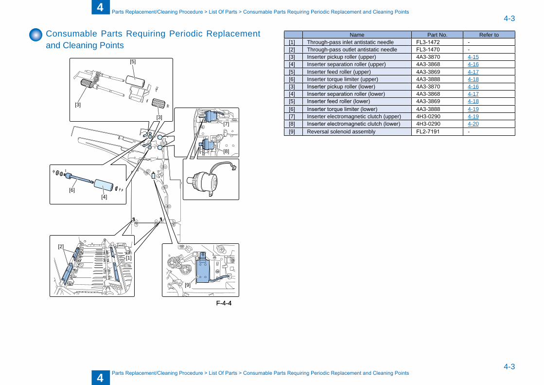
Consuma�le Parts Requiring Periodic Replacement and Cleaning Points
[5]
[3]
[3]
[6][4]
[7]
[9]
[1]
[2]
[8]
F-4-4F-4-4
№ Name Part No. Refer to[1] Through-pass inlet antistatic needle FL3-1472 -[2] Through-pass outlet antistatic needle FL3-1470 -[3] Inserter pickup roller (upper) 4A3-3870 4-15[4] Inserter separation roller (upper) 4A3-3868 4-16[5] Inserter feed roller (upper) 4A3-3869 4-17[6] Inserter torque limiter (upper) 4A3-3888 4-18[3] Inserter pickup roller (lower) 4A3-3870 4-16[4] Inserter separation roller (lower) 4A3-3868 4-17[5] Inserter feed roller (lower) 4A3-3869 4-18[6] Inserter torque limiter (lower) 4A3-3888 4-19[7] Inserter electromagnetic clutch (upper) 4H3-0290 4-19[8] Inserter electromagnetic clutch (lower) 4H3-0290 4-20[9] Reversal solenoid assem�ly FL2-7191 -
4
44-4
4-4
Parts Replacement/Cleaning Procedure > List Of Parts > Motors/PCBs/Others
Parts Replacement/Cleaning Procedure > List Of Parts > Motors/PCBs/Others
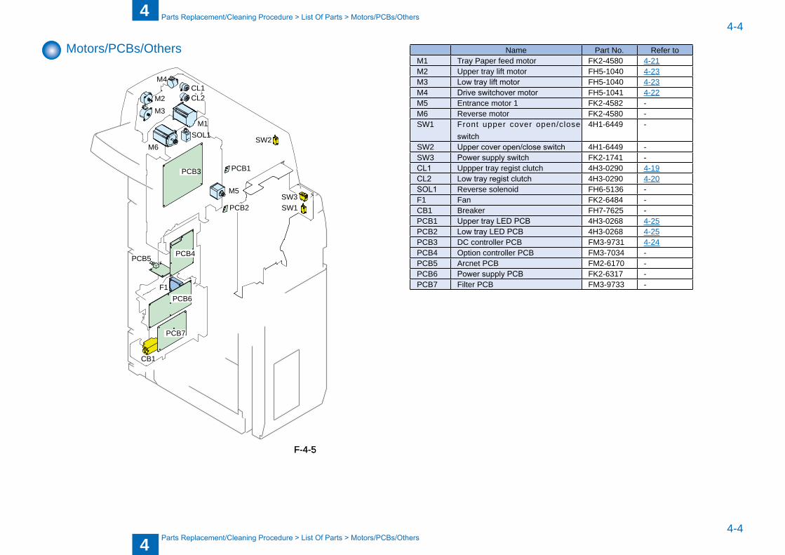
Motors/PCBs/Others
PCB3
PCB4
PCB6
PCB5
PCB7
SOL1
SW3SW1
SW2
CL1
CB1
F1
CL2
M4
M2
M1
M5
PCB1
PCB2
M3
M6
F-4-5F-4-5
№ Name Part No. Refer toM1 Tray Paper feed motor FK2-4580 4-21M2 Upper tray lift motor FH5-1040 4-23M3 Low tray lift motor FH5-1040 4-23M4 Drive switchover motor FH5-1041 4-22M5 Entrance motor 1 FK2-4582 -M6 Reverse motor FK2-4580 -SW1 Front upper cover open/close
switch4H1-6449 -
SW2 Upper cover open/close switch 4H1-6449 -SW3 Power supply switch FK2-1741 -CL1 Uppper tray regist clutch 4H3-0290 4-19CL2 Low tray regist clutch 4H3-0290 4-20SOL1 Reverse solenoid FH6-5136 -F1 Fan FK2-6484 -CB1 Breaker FH7-7625 -PCB1 Upper tray LED PCB 4H3-0268 4-25PCB2 Low tray LED PCB 4H3-0268 4-25PCB3 DC controller PCB FM3-9731 4-24PCB4 Option controller PCB FM3-7034 -PCB5 Arcnet PCB FM2-6170 -PCB6 Power supply PCB FK2-6317 -PCB7 Filter PCB FM3-9733 -
4
44-5
4-5
Parts Replacement/Cleaning Procedure > List Of Parts > List of Sensors
Parts Replacement/Cleaning Procedure > List Of Parts > List of Sensors
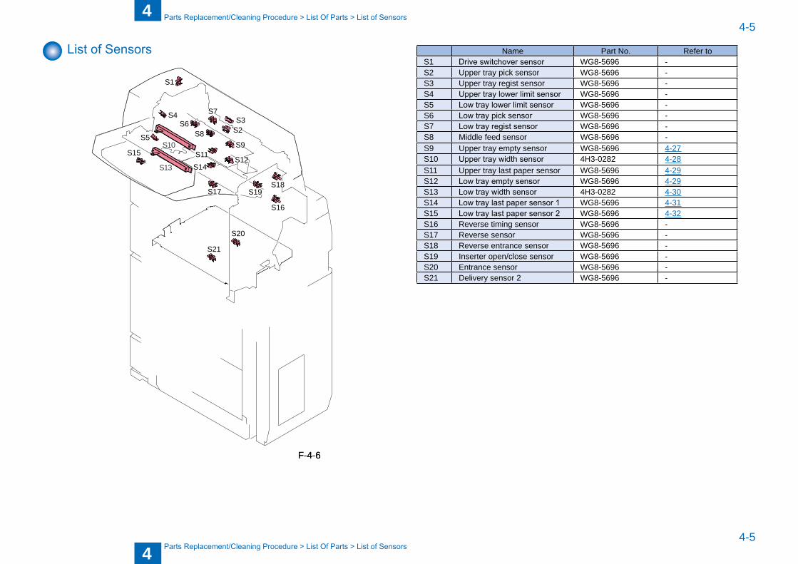
List of Sensors
S15
S5
S4S6
S9
S16
S20
S21
S18S17
S14S12
S19
S1
S3S7
S2S8
S11
S13
S10
F-4-6F-4-6
№ Name Part No. Refer toS1 Drive switchover sensor WG8-5696 -S2 Upper tray pick sensor WG8-5696 -S3 Upper tray regist sensor WG8-5696 -S4 Upper tray lower limit sensor WG8-5696 -S5 Low tray lower limit sensor WG8-5696 -S6 Low tray pick sensor WG8-5696 -S7 Low tray regist sensor WG8-5696 -S8 Middle feed sensor WG8-5696 -S9 Upper tray empty sensor WG8-5696 4-27S10 Upper tray width sensor 4H3-0282 4-28S11 Upper tray last paper sensor WG8-5696 4-29S12 Low tray empty sensor WG8-5696 4-29S13 Low tray width sensor 4H3-0282 4-30S14 Low tray last paper sensor 1 WG8-5696 4-31S15 Low tray last paper sensor 2 WG8-5696 4-32S16 Reverse timing sensor WG8-5696 -S17 Reverse sensor WG8-5696 -S18 Reverse entrance sensor WG8-5696 -S19 Inserter open/close sensor WG8-5696 -S20 Entrance sensor WG8-5696 -S21 Delivery sensor 2 WG8-5696 -
4
44-6
4-6
Parts Replacement/Cleaning Procedure > External/Innernal Covers > Removing the Rear Upper Cover
Parts Replacement/Cleaning Procedure > External/Innernal Covers > Removing the Rear Upper Cover
External/Innernal Covers
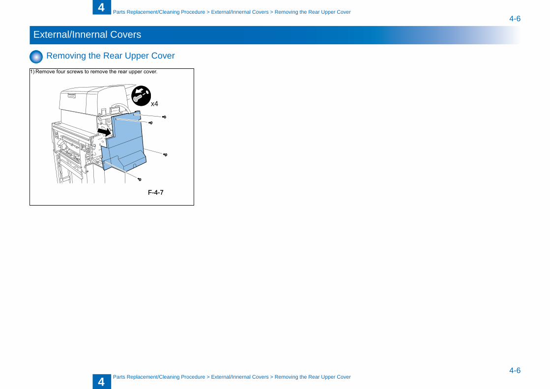
Removing the Rear Upper Cover
1) Remove four screws to remove the rear upper cover.
x4
F-4-7F-4-7
4
44-7
4-7
Parts Replacement/Cleaning Procedure > External/Innernal Covers > Removing the Front Upper Cover
Parts Replacement/Cleaning Procedure > External/Innernal Covers > Removing the Front Upper Cover
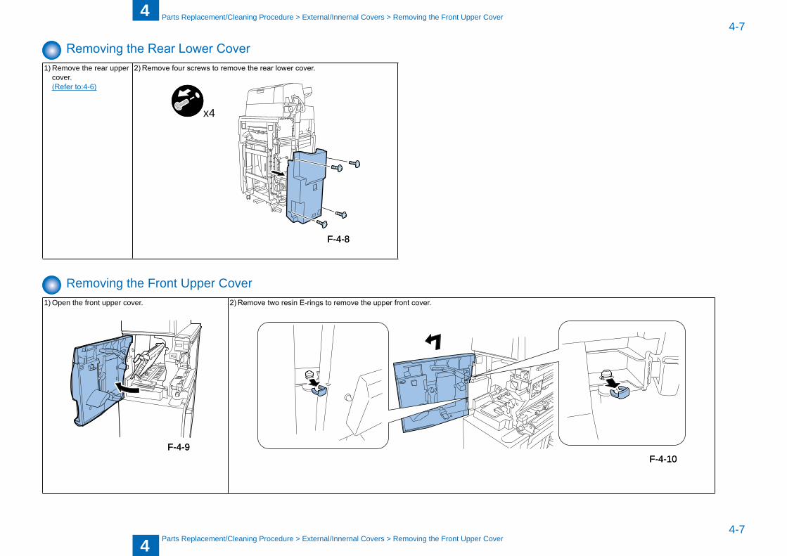
Removing the Rear Lower Cover1) Remove the rear upper
cover. (Refer to:4-6)
2) Remove four screws to remove the rear lower cover.
x4
Removing the Front Upper Cover1) Open the front upper cover. 2) Remove two resin E-rings to remove the upper front cover.
F-4-8F-4-8
F-4-9F-4-9F-4-10F-4-10
4
44-8
4-8
Parts Replacement/Cleaning Procedure > External/Innernal Covers > Removing the Front Inner Cover
Parts Replacement/Cleaning Procedure > External/Innernal Covers > Removing the Front Inner Cover
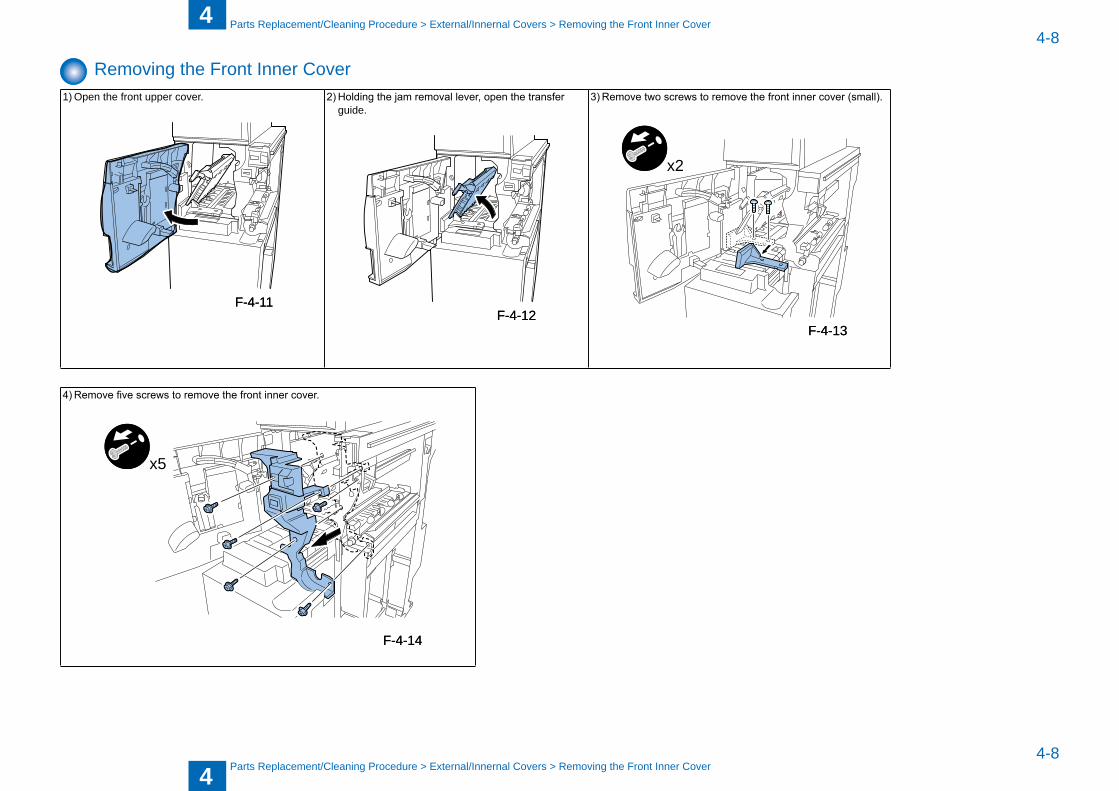
Removing the Front Inner Cover1) Open the front upper cover. 2) Holding the jam removal lever, open the transfer
guide.3) Remove two screws to remove the front inner cover (small).
x2
4) Remove five screws to remove the front inner cover.
x5
F-4-11F-4-11F-4-12F-4-12
F-4-13F-4-13
F-4-14F-4-14
4
44-9
4-9
Parts Replacement/Cleaning Procedure > External/Innernal Covers > Changing the Inserter Top Cover Open/Close Angle
Parts Replacement/Cleaning Procedure > External/Innernal Covers > Changing the Inserter Top Cover Open/Close Angle
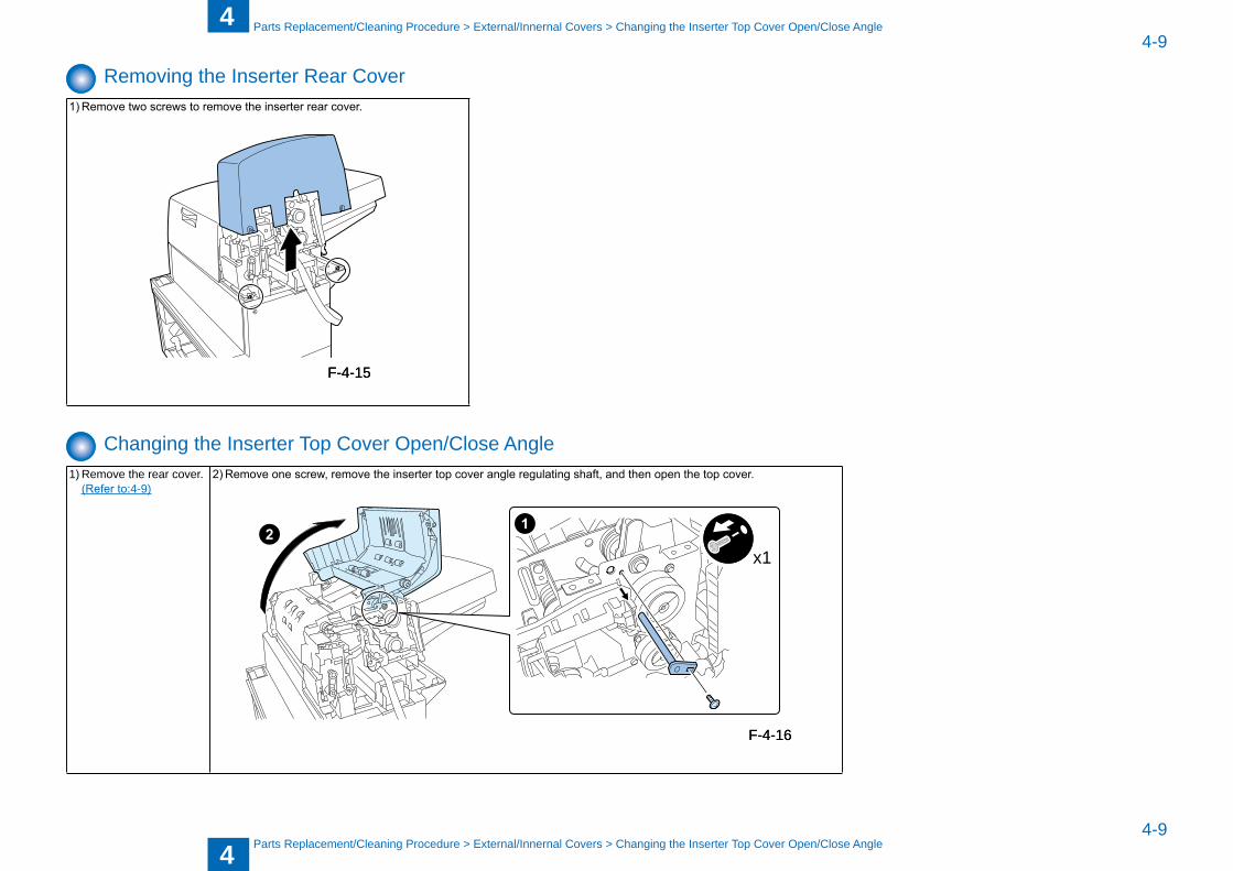
Removing the Inserter Rear Cover1) Remove two screws to remove the inserter rear cover.
Changing the Inserter Top Cover Open/Close Angle1) Remove the rear cover. (Refer to:4-9)
2) Remove one screw, remove the inserter top cover angle regulating shaft, and then open the top cover.
x1
F-4-15F-4-15
F-4-16F-4-16
4
44-10
4-10
Parts Replacement/Cleaning Procedure > External/Innernal Covers > Changing the Middle Guide Open/Close Angle
Parts Replacement/Cleaning Procedure > External/Innernal Covers > Changing the Middle Guide Open/Close Angle
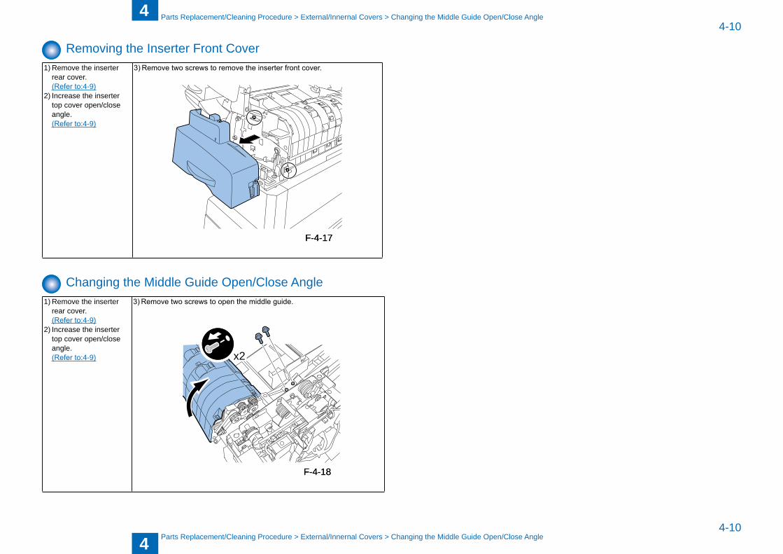
Removing the Inserter Front Cover1) Remove the inserter
rear cover. (Refer to:4-9)2) Increase the inserter
top cover open/close angle.
(Refer to:4-9)
3) Remove two screws to remove the inserter front cover.
Changing the Middle Guide Open/Close Angle1) Remove the inserter
rear cover. (Refer to:4-9)2) Increase the inserter
top cover open/close angle.
(Refer to:4-9)
3) Remove two screws to open the middle guide.
x2
F-4-17F-4-17
F-4-18F-4-18
4
44-11
4-11
Parts Replacement/Cleaning Procedure > External/Innernal Covers > Changing the Inserter Open Angle
Parts Replacement/Cleaning Procedure > External/Innernal Covers > Changing the Inserter Open Angle
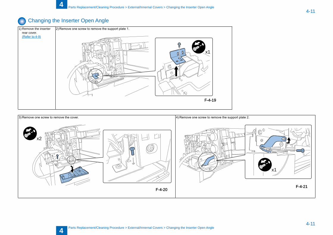
Changing the Inserter Open Angle1) Remove the inserter
rear cover. (Refer to:4-9)
2) Remove one screw to remove the support plate 1.
x1
3) Remove one screw to remove the cover.
x2
4) Remove one screw to remove the support plate 2.
x1
F-4-19F-4-19
F-4-20F-4-20F-4-21F-4-21
4
44-12
4-12
Parts Replacement/Cleaning Procedure > Removing the Main Unit > Removing the Upper Tray Unit
Parts Replacement/Cleaning Procedure > Removing the Main Unit > Removing the Upper Tray Unit
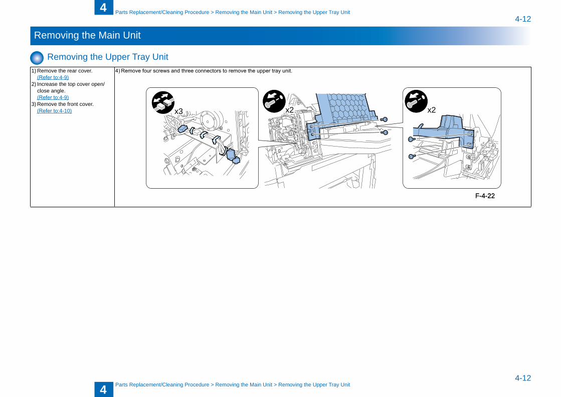
Removing the Main Unit
Removing the Upper Tray Unit1) Remove the rear cover. (Refer to:4-9)2) Increase the top cover open/
close angle. (Refer to:4-9)3) Remove the front cover. (Refer to:4-10)
4) Remove four screws and three connectors to remove the upper tray unit.
x2 x2x3
F-4-22F-4-22
4
44-13
4-13
Parts Replacement/Cleaning Procedure > Removing the Main Unit > Removing the Inserter Pickup Unit
Parts Replacement/Cleaning Procedure > Removing the Main Unit > Removing the Inserter Pickup Unit
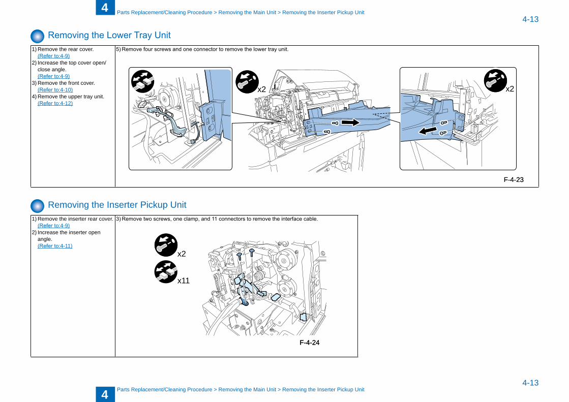
Removing the Lower Tray Unit1) Remove the rear cover. (Refer to:4-9)2) Increase the top cover open/
close angle. (Refer to:4-9)3) Remove the front cover. (Refer to:4-10)4) Remove the upper tray unit. (Refer to:4-12)
5) Remove four screws and one connector to remove the lower tray unit.
x2 x2
Removing the Inserter Pickup Unit1) Remove the inserter rear cover. (Refer to:4-9)2) Increase the inserter open
angle. (Refer to:4-11)
3) Remove two screws, one clamp, and 11 connectors to remove the interface cable.
x2
x11
F-4-23F-4-23
F-4-24F-4-24
4
44-14
4-14
Parts Replacement/Cleaning Procedure > Removing the Main Unit > Removing the Inserter Pickup Unit
Parts Replacement/Cleaning Procedure > Removing the Main Unit > Removing the Inserter Pickup Unit
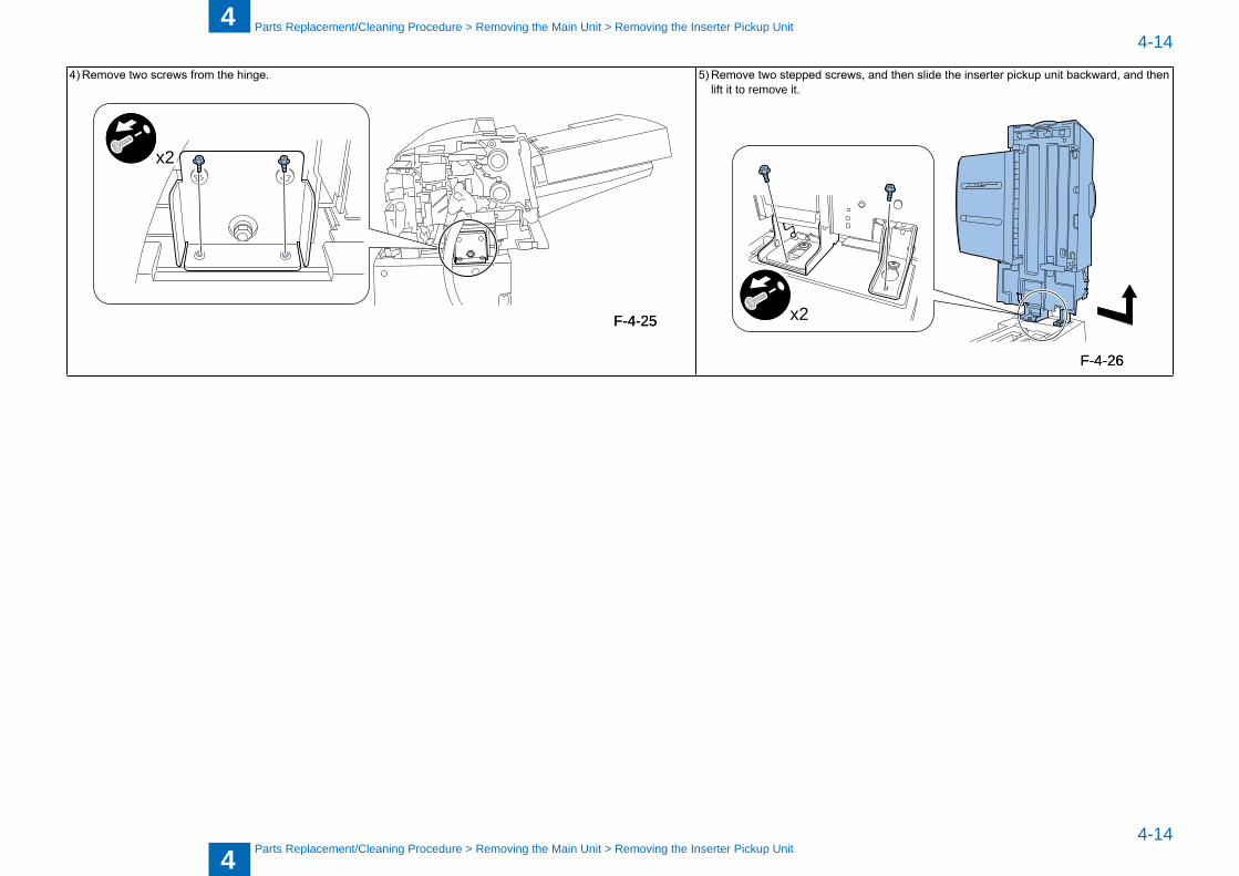
4) Remove two screws from the hinge.
x2
5) Remove two stepped screws, and then slide the inserter pickup unit backward, and then lift it to remove it.
x2F-4-25F-4-25
F-4-26F-4-26
4
44-15
4-15
Parts Replacement/Cleaning Procedure > Consuma�le Parts Requiring Periodic Replacement and Cleaning Points > Removing the Inserter pickup rollers (upper)
Parts Replacement/Cleaning Procedure > Consuma�le Parts Requiring Periodic Replacement and Cleaning Points > Removing the Inserter pickup rollers (upper)
Consuma�le Parts Requiring Periodic Replacement and Cleaning Points
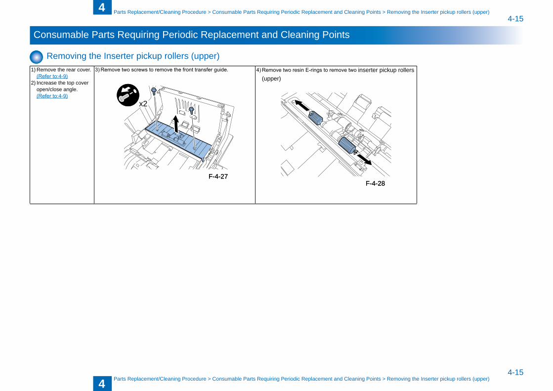
Removing the Inserter pickup rollers (upper)1) Remove the rear cover. (Refer to:4-9)2) Increase the top cover
open/close angle. (Refer to:4-9)
3) Remove two screws to remove the front transfer guide.
x2
4) Remove two resin E-rings to remove two inserter pickup rollers (upper)
F-4-27F-4-27F-4-28F-4-28
4
44-16
4-16
Parts Replacement/Cleaning Procedure > Consuma�le Parts Requiring Periodic Replacement and Cleaning Points > Removing the Inserter separation roller (upper)
Parts Replacement/Cleaning Procedure > Consuma�le Parts Requiring Periodic Replacement and Cleaning Points > Removing the Inserter separation roller (upper)
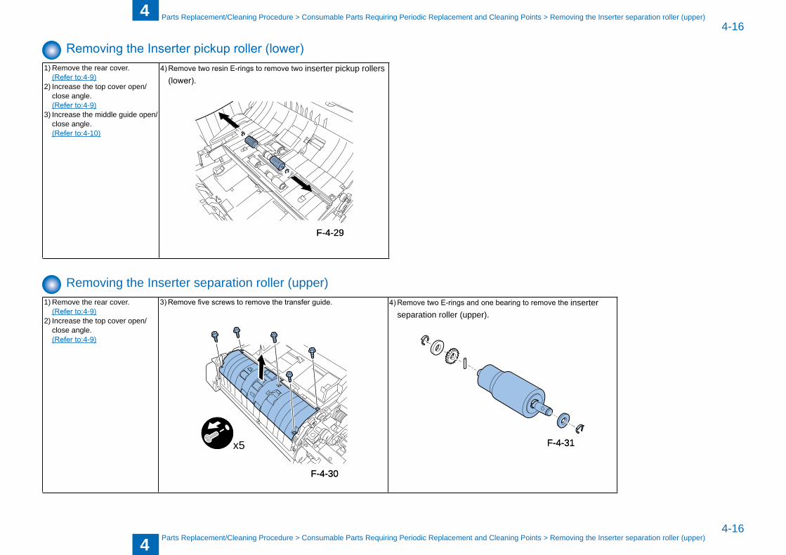
Removing the Inserter pickup roller (lower)1) Remove the rear cover. (Refer to:4-9)2) Increase the top cover open/
close angle. (Refer to:4-9)3) Increase the middle guide open/
close angle. (Refer to:4-10)
4) Remove two resin E-rings to remove two inserter pickup rollers (lower).
Removing the Inserter separation roller (upper)1) Remove the rear cover. (Refer to:4-9)2) Increase the top cover open/
close angle. (Refer to:4-9)
3) Remove five screws to remove the transfer guide.
x5
4) Remove two E-rings and one bearing to remove the inserter separation roller (upper).
F-4-29F-4-29
F-4-30F-4-30
F-4-31F-4-31
4
44-17
4-17
Parts Replacement/Cleaning Procedure > Consuma�le Parts Requiring Periodic Replacement and Cleaning Points > Removing the Inserter feed roller (upper)
Parts Replacement/Cleaning Procedure > Consuma�le Parts Requiring Periodic Replacement and Cleaning Points > Removing the Inserter feed roller (upper)
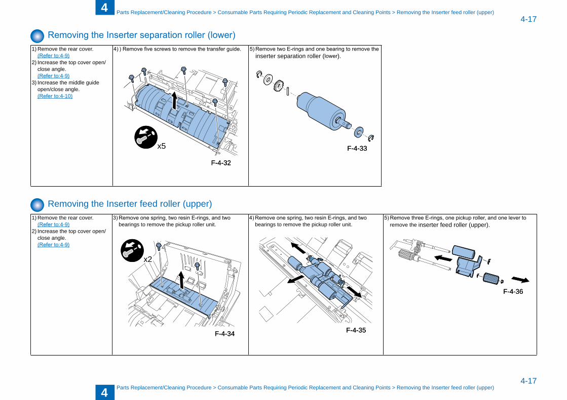
Removing the Inserter separation roller (lower)1) Remove the rear cover. (Refer to:4-9)2) Increase the top cover open/
close angle. (Refer to:4-9)3) Increase the middle guide
open/close angle. (Refer to:4-10)
4) ) Remove five screws to remove the transfer guide.
x5
5) Remove two E-rings and one bearing to remove the inserter separation roller (lower).
Removing the Inserter feed roller (upper)1) Remove the rear cover. (Refer to:4-9)2) Increase the top cover open/
close angle. (Refer to:4-9)
3) Remove one spring, two resin E-rings, and two �earings to remove the pickup roller unit.
x2
4) Remove one spring, two resin E-rings, and two �earings to remove the pickup roller unit.
5) Remove three E-rings, one pickup roller, and one lever to remove the inserter feed roller (upper).
F-4-32F-4-32
F-4-33F-4-33
F-4-34F-4-34 F-4-35F-4-35
F-4-36F-4-36
4
44-18
4-18
Parts Replacement/Cleaning Procedure > Consuma�le Parts Requiring Periodic Replacement and Cleaning Points > Removing the Inserter torque limiter (upper)
Parts Replacement/Cleaning Procedure > Consuma�le Parts Requiring Periodic Replacement and Cleaning Points > Removing the Inserter torque limiter (upper)
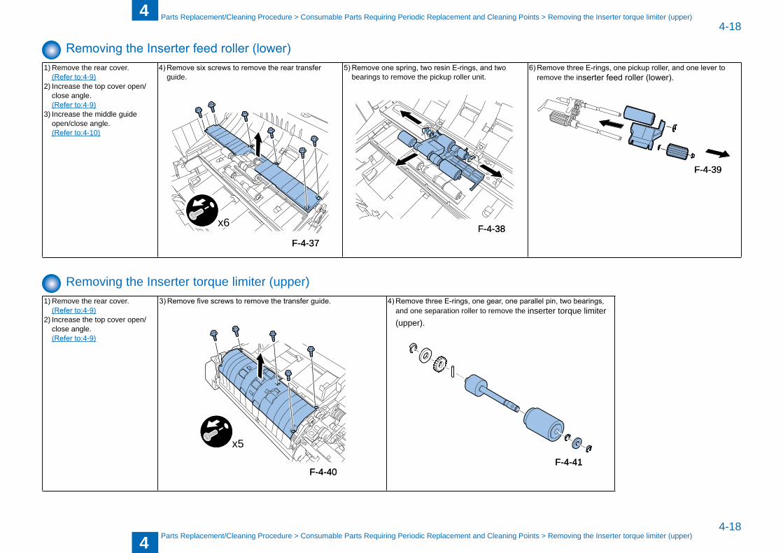
Removing the Inserter feed roller (lower)1) Remove the rear cover. (Refer to:4-9)2) Increase the top cover open/
close angle. (Refer to:4-9)3) Increase the middle guide
open/close angle. (Refer to:4-10)
4) Remove six screws to remove the rear transfer guide.
x6
5) Remove one spring, two resin E-rings, and two �earings to remove the pickup roller unit.
6) Remove three E-rings, one pickup roller, and one lever to remove the inserter feed roller (lower).
Removing the Inserter torque limiter (upper)1) Remove the rear cover. (Refer to:4-9)2) Increase the top cover open/
close angle. (Refer to:4-9)
3) Remove five screws to remove the transfer guide.
x5
4) Remove three E-rings, one gear, one parallel pin, two bearings, and one separation roller to remove the inserter torque limiter (upper).
F-4-37F-4-37F-4-38F-4-38
F-4-39F-4-39
F-4-40F-4-40F-4-41F-4-41
4
44-19
4-19
Parts Replacement/Cleaning Procedure > Consuma�le Parts Requiring Periodic Replacement and Cleaning Points > Removing the Inserter electromagnetic clutch (upper)
Parts Replacement/Cleaning Procedure > Consuma�le Parts Requiring Periodic Replacement and Cleaning Points > Removing the Inserter electromagnetic clutch (upper)
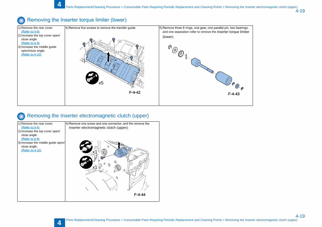
Removing the Inserter torque limiter (lower)1) Remove the rear cover. (Refer to:4-9)2) Increase the top cover open/
close angle. (Refer to:4-9)3) Increase the middle guide
open/close angle. (Refer to:4-10)
4) Remove five screws to remove the transfer guide.
x5
5) Remove three E-rings, one gear, one parallel pin, two bearings, and one separation roller to remove the inserter torque limiter (lower).
Removing the Inserter electromagnetic clutch (upper)1) Remove the rear cover. (Refer to:4-9)2) Increase the top cover open/
close angle. (Refer to:4-9)3) Increase the middle guide open/
close angle. (Refer to:4-10)
4) Remove one screw and one connector, and the remove the inserter electromagnetic clutch (upper).
x1
x1
F-4-42F-4-42 F-4-43F-4-43
F-4-44F-4-44
4
44-20
4-20
Parts Replacement/Cleaning Procedure > Consumable Parts Requiring Periodic Replacement and Cleaning Points > Removing the Inserter electromagnetic clutch (lower)
Parts Replacement/Cleaning Procedure > Consumable Parts Requiring Periodic Replacement and Cleaning Points > Removing the Inserter electromagnetic clutch (lower)
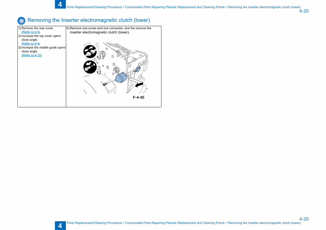
Removing the Inserter electromagnetic clutch (lower)1) Remove the rear cover. (Refer to:4-9)2) Increase the top cover open/
close angle. (Refer to:4-9)3) Increase the middle guide open/
close angle. (Refer to:4-10)
4) Remove one screw and one connector, and the remove the inserter electromagnetic clutch (lower).
x1
x1
F-4-45F-4-45
4
44-21
4-21
Parts Replacement/Cleaning Procedure > Removing the Motor > Removing the Tray Pickup Motor (M1)
Parts Replacement/Cleaning Procedure > Removing the Motor > Removing the Tray Pickup Motor (M1)
Removing the Motor
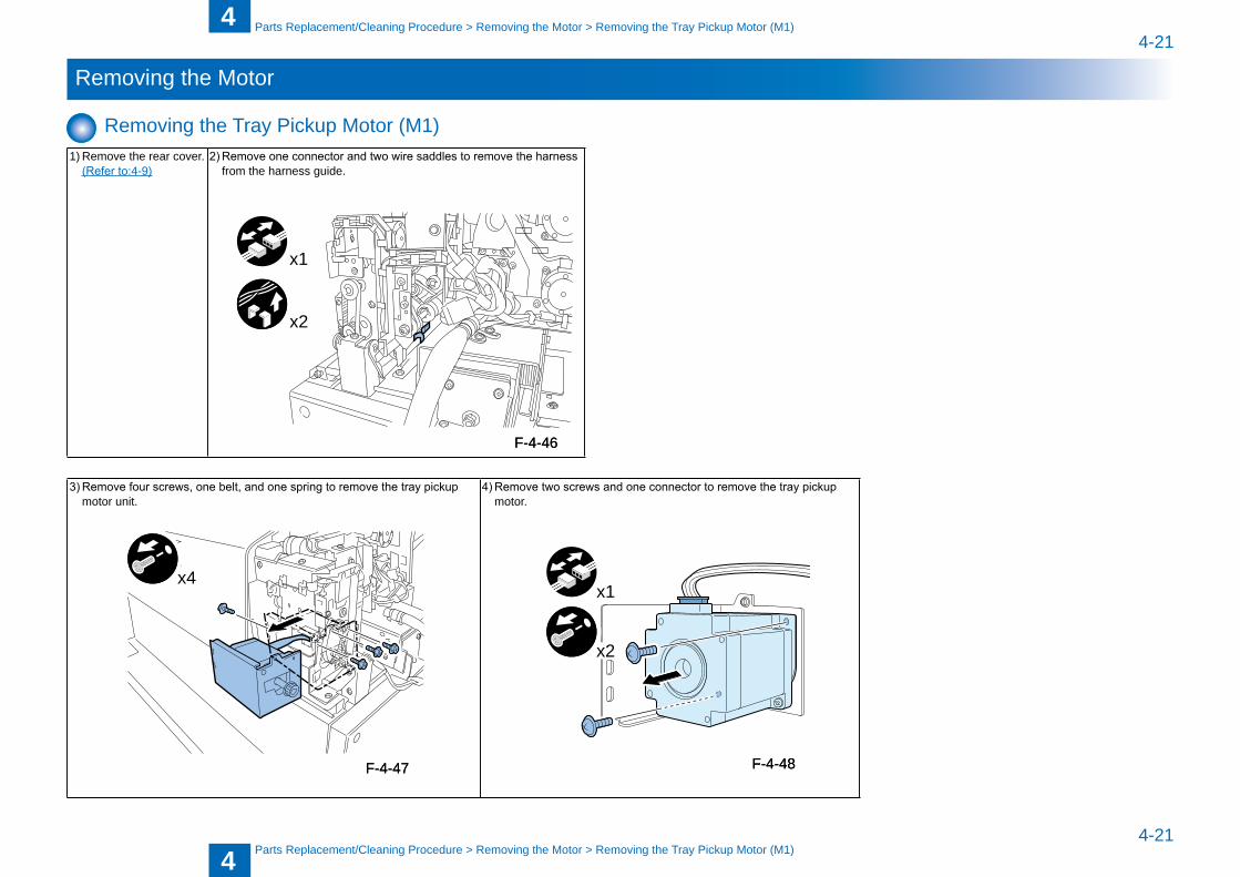
Removing the Tray Pickup Motor (M1)1) Remove the rear cover. (Refer to:4-9)
2) Remove one connector and two wire saddles to remove the harness from the harness guide.
x1
x2
3) Remove four screws, one belt, and one spring to remove the tray pickup motor unit.
x4
4) Remove two screws and one connector to remove the tray pickup motor.
x2
x1
F-4-46F-4-46
F-4-47F-4-47 F-4-48F-4-48
4
44-22
4-22
Parts Replacement/Cleaning Procedure > Removing the Motor > Removing the Drive Switchover Motor (M4)
Parts Replacement/Cleaning Procedure > Removing the Motor > Removing the Drive Switchover Motor (M4)
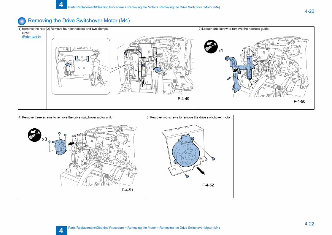
Removing the Drive Switchover Motor (M4)1) Remove the rear
cover. (Refer to:4-9)
2) Remove four connectors and two clamps. 2) Loosen one screw to remove the harness guide.
x1
4) Remove three screws to remove the drive switchover motor unit.
x3
5) Remove two screws to remove the drive switchover motor.
F-4-49F-4-49F-4-50F-4-50
F-4-51F-4-51F-4-52F-4-52
4
44-23
4-23
Parts Replacement/Cleaning Procedure > Removing the Motor > Removing the Lower Tray Lift Motor (M3)
Parts Replacement/Cleaning Procedure > Removing the Motor > Removing the Lower Tray Lift Motor (M3)
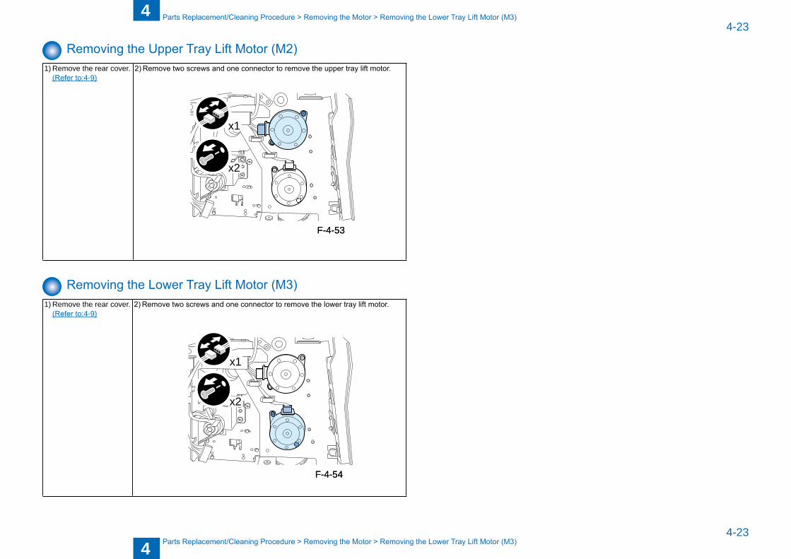
Removing the Upper Tray Lift Motor (M2)1) Remove the rear cover. (Refer to:4-9)
2) Remove two screws and one connector to remove the upper tray lift motor.
x2
x1
Removing the Lower Tray Lift Motor (M3)1) Remove the rear cover. (Refer to:4-9)
2) Remove two screws and one connector to remove the lower tray lift motor.
x2
x1
F-4-53F-4-53
F-4-54F-4-54
4
44-24
4-24
Parts Replacement/Cleaning Procedure > Removing the PCB > Removing the DC Controller PCB
Parts Replacement/Cleaning Procedure > Removing the PCB > Removing the DC Controller PCB
Removing the PCB
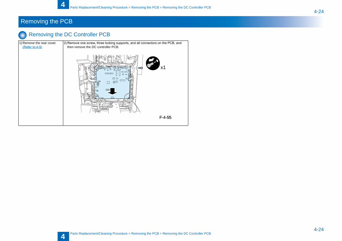
Removing the DC Controller PCB 1) Remove the rear cover. (Refer to:4-9)
2) Remove one screw, three locking supports, and all connectors on the PCB, and then remove the DC controller PCB.
x1
F-4-55F-4-55
4
44-25
4-25
Parts Replacement/Cleaning Procedure > Removing the PCB > Removing the Lower Tray LED PCB
Parts Replacement/Cleaning Procedure > Removing the PCB > Removing the Lower Tray LED PCB
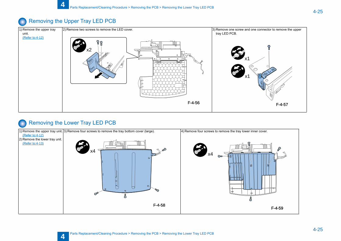
Removing the Upper Tray LED PCB1) Remove the upper tray
unit. (Refer to:4-12)
2) Remove two screws to remove the LED cover.
x2
3) Remove one screw and one connector to remove the upper tray LED PCB.
x1
x1
Removing the Lower Tray LED PCB1) Remove the upper tray unit. (Refer to:4-12)2) Remove the lower tray unit. (Refer to:4-13)
3) Remove four screws to remove the tray bottom cover (large).
x4
4) Remove four screws to remove the tray lower inner cover.
x4
F-4-56F-4-56 F-4-57F-4-57
F-4-58F-4-58F-4-59F-4-59
4
44-26
4-26
Parts Replacement/Cleaning Procedure > Removing the PCB > Removing the Lower Tray LED PCB
Parts Replacement/Cleaning Procedure > Removing the PCB > Removing the Lower Tray LED PCB
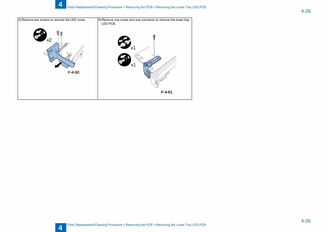
5) Remove two screws to remove the LED cover.
x2
6) Remove one screw and one connector to remove the lower tray LED PCB.
x1
x1
F-4-60F-4-60
F-4-61F-4-61
4
44-27
4-27
Parts Replacement/Cleaning Procedure > Removing the Sensor > Removing the Upper tray empty sensor (S9)
Parts Replacement/Cleaning Procedure > Removing the Sensor > Removing the Upper tray empty sensor (S9)
Removing the Sensor
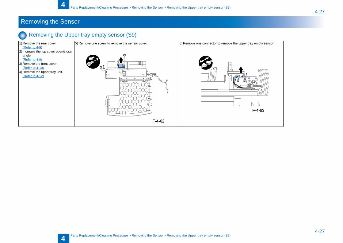
Removing the Upper tray empty sensor (S9) 1) Remove the rear cover. (Refer to:4-9)2) Increase the top cover open/close
angle. (Refer to:4-9)3) Remove the front cover. (Refer to:4-10)4) Remove the upper tray unit. (Refer to:4-12)
5) Remove one screw to remove the sensor cover.
x1
6) Remove one connector to remove the upper tray empty sensor.
x1
F-4-62F-4-62
F-4-63F-4-63
4
44-28
4-28
Parts Replacement/Cleaning Procedure > Removing the Sensor > Removing the Upper tray width sensor (S10)
Parts Replacement/Cleaning Procedure > Removing the Sensor > Removing the Upper tray width sensor (S10)
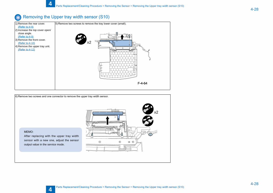
Removing the Upper tray width sensor (S10)1) Remove the rear cover. (Refer to:4-9)2) Increase the top cover open/
close angle. (Refer to:4-9)3) Remove the front cover. (Refer to:4-10)4) Remove the upper tray unit. (Refer to:4-12)
5) Remove two screws to remove the tray lower cover (small).
x2
6) Remove two screws and one connector to remove the upper tray width sensor.
MEMO:After replacing with the upper tray width sensor with a new one, adjust the sensor output value in the service mode.
x2
F-4-64F-4-64
4
44-29
4-29
Parts Replacement/Cleaning Procedure > Removing the Sensor > Removing the Low tray empty sensor (S12)
Parts Replacement/Cleaning Procedure > Removing the Sensor > Removing the Low tray empty sensor (S12)
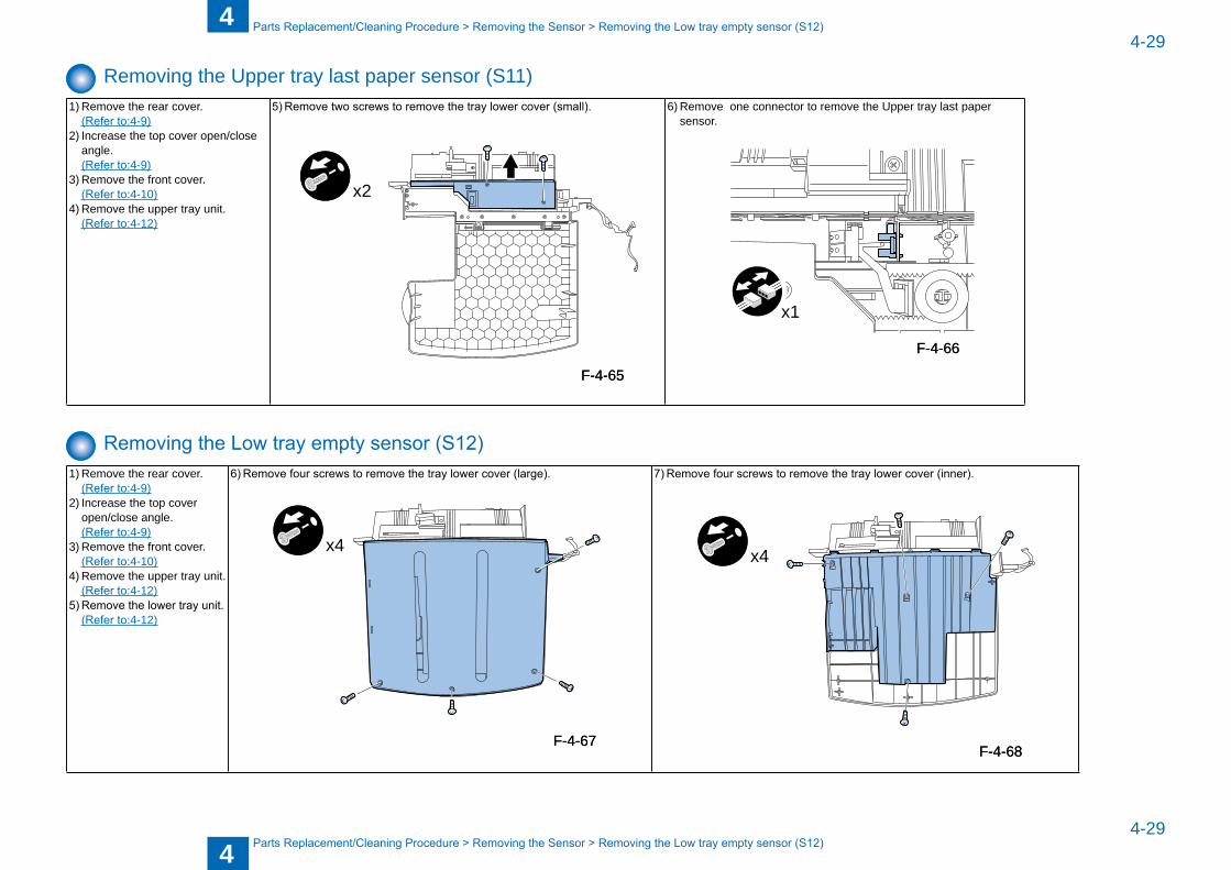
Removing the Upper tray last paper sensor (S11)1) Remove the rear cover. (Refer to:4-9)2) Increase the top cover open/close
angle. (Refer to:4-9)3) Remove the front cover. (Refer to:4-10)4) Remove the upper tray unit. (Refer to:4-12)
5) Remove two screws to remove the tray lower cover (small).
x2
6) Remove one connector to remove the Upper tray last paper sensor.
x1
Removing the Low tray empty sensor (S12)1) Remove the rear cover. (Refer to:4-9)2) Increase the top cover
open/close angle. (Refer to:4-9)3) Remove the front cover. (Refer to:4-10)4) Remove the upper tray unit. (Refer to:4-12)5) Remove the lower tray unit. (Refer to:4-12)
6) Remove four screws to remove the tray lower cover (large).
x4
7) Remove four screws to remove the tray lower cover (inner).
x4
F-4-65F-4-65
F-4-66F-4-66
F-4-67F-4-67F-4-68F-4-68
4
44-30
4-30
Parts Replacement/Cleaning Procedure > Removing the Sensor > Removing the Low tray width sensor (S13)
Parts Replacement/Cleaning Procedure > Removing the Sensor > Removing the Low tray width sensor (S13)
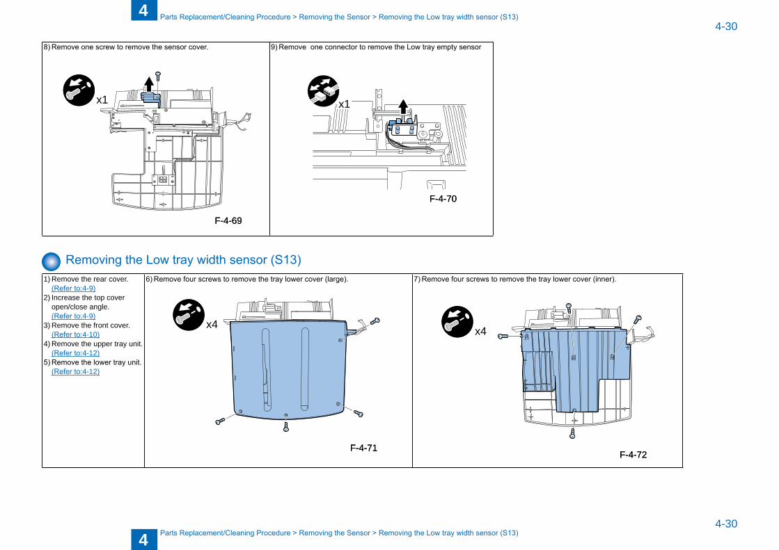
8) Remove one screw to remove the sensor cover.
x1
9) Remove one connector to remove the Low tray empty sensor
x1
Removing the Low tray width sensor (S13)1) Remove the rear cover. (Refer to:4-9)2) Increase the top cover
open/close angle. (Refer to:4-9)3) Remove the front cover. (Refer to:4-10)4) Remove the upper tray unit. (Refer to:4-12)5) Remove the lower tray unit. (Refer to:4-12)
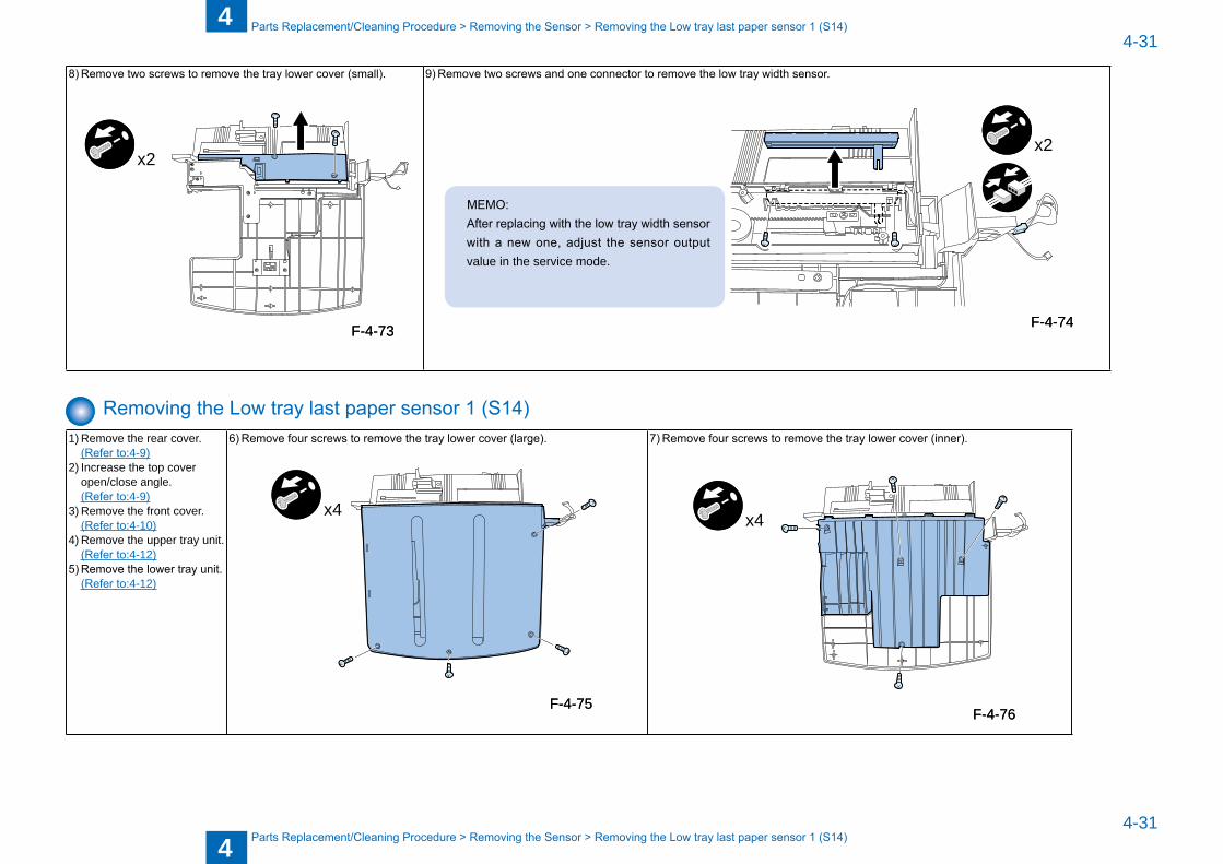
6) Remove four screws to remove the tray lower cover (large).
x4
7) Remove four screws to remove the tray lower cover (inner).
x4
F-4-69F-4-69
F-4-70F-4-70
F-4-71F-4-71F-4-72F-4-72
4
44-31
4-31
Parts Replacement/Cleaning Procedure > Removing the Sensor > Removing the Low tray last paper sensor 1 (S14)
Parts Replacement/Cleaning Procedure > Removing the Sensor > Removing the Low tray last paper sensor 1 (S14)
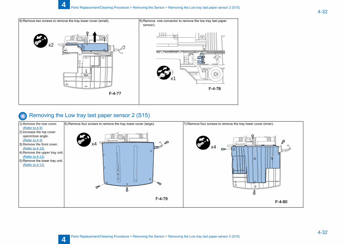
8) Remove two screws to remove the tray lower cover (small).
x2
9) Remove two screws and one connector to remove the low tray width sensor.
MEMO:After replacing with the low tray width sensor with a new one, adjust the sensor output value in the service mode.
x2
Removing the Low tray last paper sensor 1 (S14)1) Remove the rear cover. (Refer to:4-9)2) Increase the top cover
open/close angle. (Refer to:4-9)3) Remove the front cover. (Refer to:4-10)4) Remove the upper tray unit. (Refer to:4-12)5) Remove the lower tray unit. (Refer to:4-12)
6) Remove four screws to remove the tray lower cover (large).
x4
7) Remove four screws to remove the tray lower cover (inner).
x4
F-4-73F-4-73 F-4-74F-4-74
F-4-75F-4-75F-4-76F-4-76
4
44-32
4-32
Parts Replacement/Cleaning Procedure > Removing the Sensor > Removing the Low tray last paper sensor 2 (S15)
Parts Replacement/Cleaning Procedure > Removing the Sensor > Removing the Low tray last paper sensor 2 (S15)
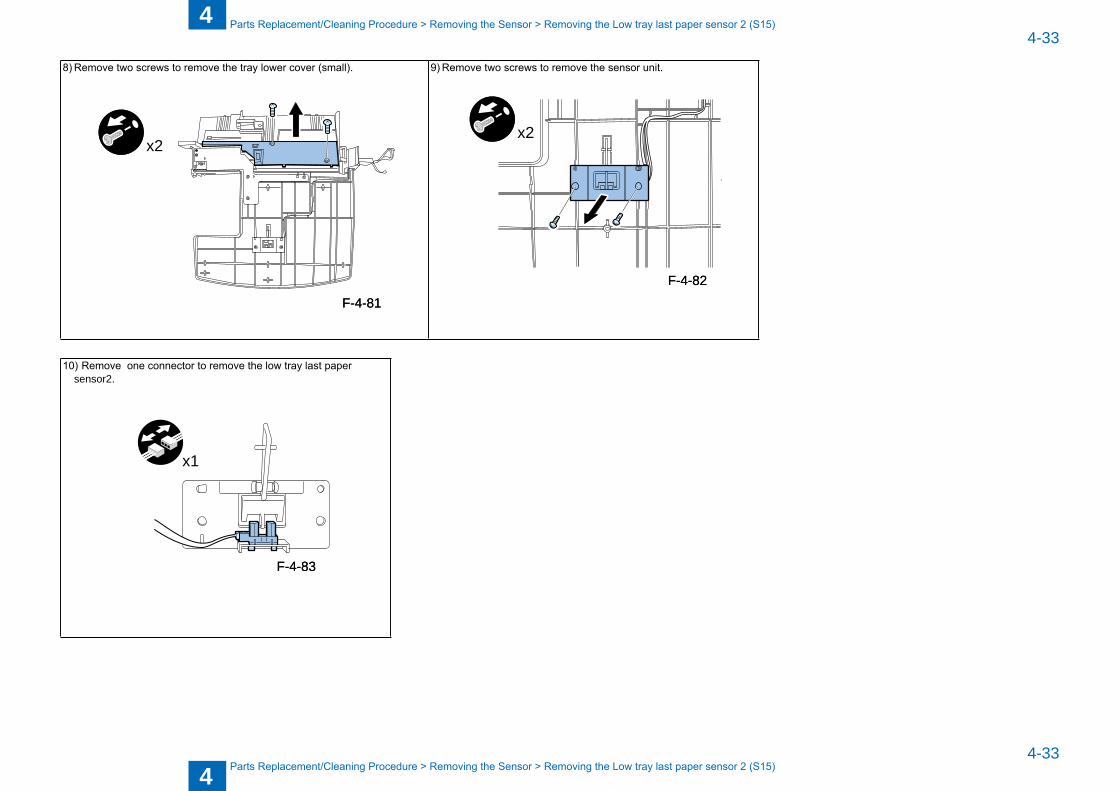
8) Remove two screws to remove the tray lower cover (small).
x2
9) Remove one connector to remove the low tray last paper sensor1.
x1
Removing the Low tray last paper sensor 2 (S15)1) Remove the rear cover. (Refer to:4-9)2) Increase the top cover
open/close angle. (Refer to:4-9)3) Remove the front cover. (Refer to:4-10)4) Remove the upper tray unit. (Refer to:4-12)5) Remove the lower tray unit. (Refer to:4-12)
6) Remove four screws to remove the tray lower cover (large).
x4
7) Remove four screws to remove the tray lower cover (inner).
x4
F-4-77F-4-77F-4-78F-4-78
F-4-79F-4-79F-4-80F-4-80
4
44-33
4-33
Parts Replacement/Cleaning Procedure > Removing the Sensor > Removing the Low tray last paper sensor 2 (S15)
Parts Replacement/Cleaning Procedure > Removing the Sensor > Removing the Low tray last paper sensor 2 (S15)
8) Remove two screws to remove the tray lower cover (small).
x2
9) Remove two screws to remove the sensor unit.
x2
z
10) Remove one connector to remove the low tray last paper sensor2.
x1
F-4-81F-4-81
F-4-82F-4-82
F-4-83F-4-83
5
5 Adjustment
AdjustmentAdjustment at Time of Parts Replacement
■
5
55-2
5-2
Adjustment > Adjustment at Time of Parts Replacement
Adjustment > Adjustment at Time of Parts Replacement
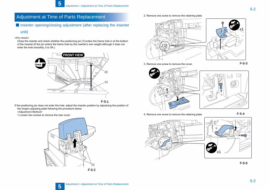
Adjustment at Time of Parts ReplacementInserter opening/closing adjustment (after replacing the inserter
unit)<Pre-check> Close the inserter and check whether the positioning pin [1] enters the frame hole in at the bottom
of the inserter.(If the pin enters the frame hole by the inserter's own weight although it does not enter the hole smoothly, it is OK.)
[1]
[2]
If the positioning pin does not enter the hole, adjust the inserter position by adjustuing the position of
the hinge's adjusting plate following the procedure below. <Adjustment Method> 1.Loosen two screws to remove the rear cover.
[1]
■
F-5-1F-5-1
F-5-2F-5-2
2. Remove one screw to remove the retaining plate.
x1
3. Remove one screw to remove the cover.
x2
4. Remove one screw to remove the retaining plate.
x1
F-5-3F-5-3
F-5-4F-5-4
F-5-5F-5-5
5
55-3
5-3
Adjustment > Adjustment at Time of Parts Replacement
Adjustment > Adjustment at Time of Parts Replacement
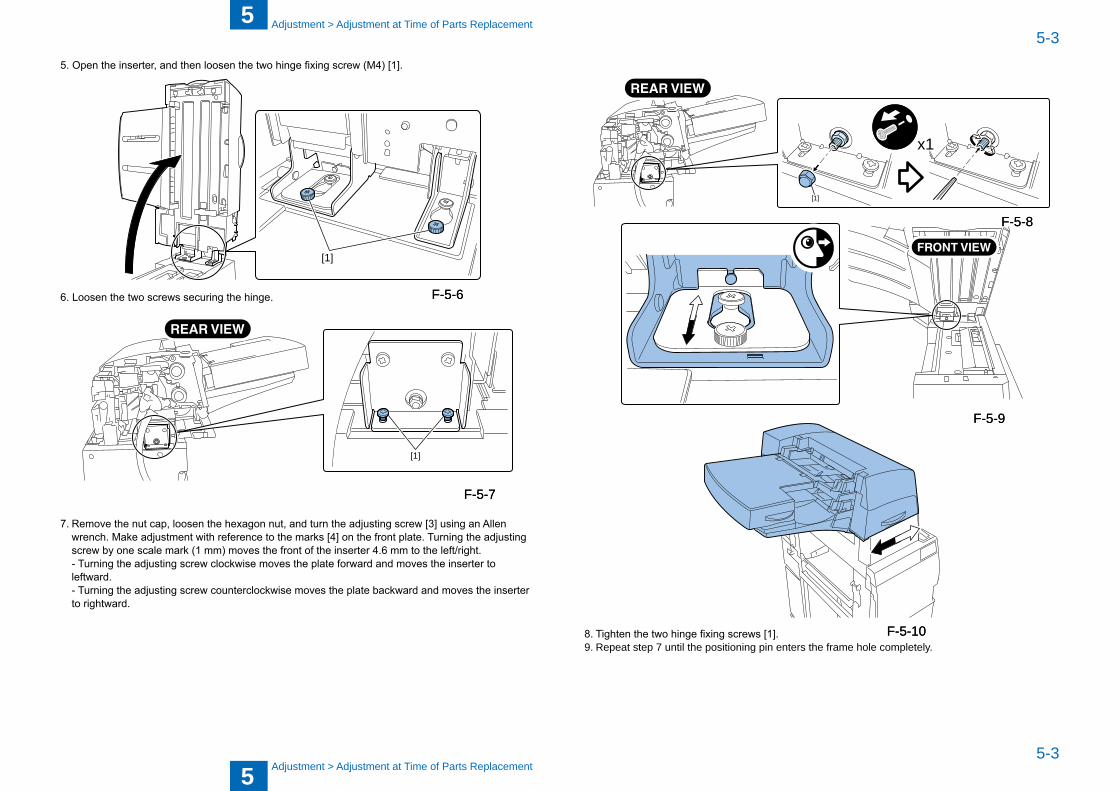
5. Open the inserter, and then loosen the two hinge fixing screw (M4) [1].
[1]
6. Loosen the two screws securing the hinge.
[1]
7. Remove the nut cap, loosen the hexagon nut, and turn the adjusting screw [3] using an Allen wrench. Make adjustment with reference to the marks [4] on the front plate. Turning the adjusting screw by one scale mark (1 mm) moves the front of the inserter 4.6 mm to the left/right.
- Turning the adjusting screw clockwise moves the plate forward and moves the inserter to leftward.
- Turning the adjusting screw counterclockwise moves the plate backward and moves the inserter to rightward.
F-5-6F-5-6
F-5-7F-5-7
[1]
x1
8. Tighten the two hinge fixing screws [1]. 9. Repeat step 7 until the positioning pin enters the frame hole completely.
F-5-8F-5-8
F-5-9F-5-9
F-5-10F-5-10
5
55-4
5-4
Adjustment > Adjustment at Time of Parts Replacement
Adjustment > Adjustment at Time of Parts Replacement
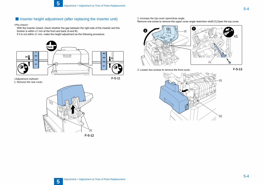
Inserter height adjustment (after replacing the inserter unit)<Pre-check> With the inserter closed, check whether the gap between the right side of the inserter and the
finisher is within ±1 mm at the front and back (A and B). If it is not within ±1 mm, make the height adjustment as the following procedure.
<Adjustment method>1. Remove the rear cover.
[1]
■
F-5-11F-5-11
F-5-12F-5-12
2. Increase the top cover open/close angle.Remove one screw to remove the upper cover angle restriction shaft [1].Open the top cover.
x1
[1]
[2]
3. Loosen two screws to remove the front cover.
[2]
[1]
F-5-13F-5-13
5
55-5
5-5
Adjustment > Adjustment at Time of Parts Replacement
Adjustment > Adjustment at Time of Parts Replacement
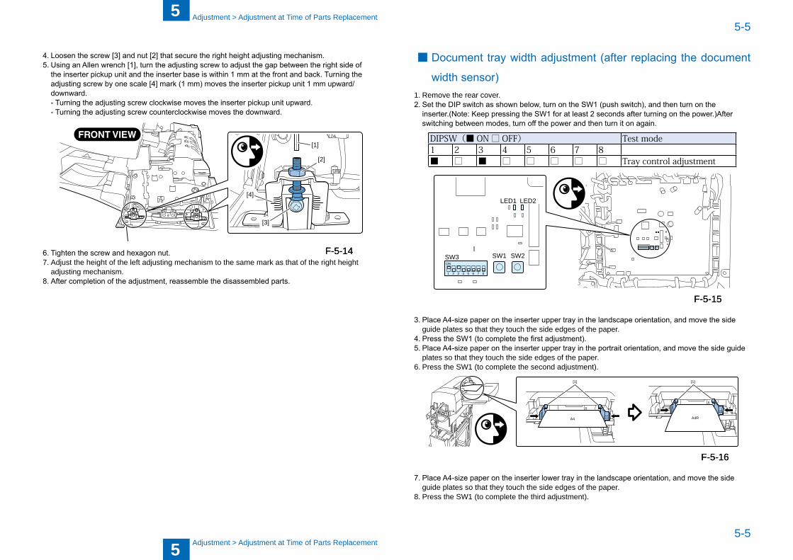
4. Loosen the screw [3] and nut [2] that secure the right height adjusting mechanism.5. Using an Allen wrench [1], turn the adjusting screw to adjust the gap between the right side of
the inserter pickup unit and the inserter base is within 1 mm at the front and back. Turning the adjusting screw by one scale [4] mark (1 mm) moves the inserter pickup unit 1 mm upward/downward.
- Turning the adjusting screw clockwise moves the inserter pickup unit upward. - Turning the adjusting screw counterclockwise moves the downward.
[3]
[1]
[2]
[4]
6. Tighten the screw and hexagon nut. 7. Adjust the height of the left adjusting mechanism to the same mark as that of the right height
adjusting mechanism. 8. After completion of the adjustment, reassemble the disassembled parts.
F-5-14F-5-14
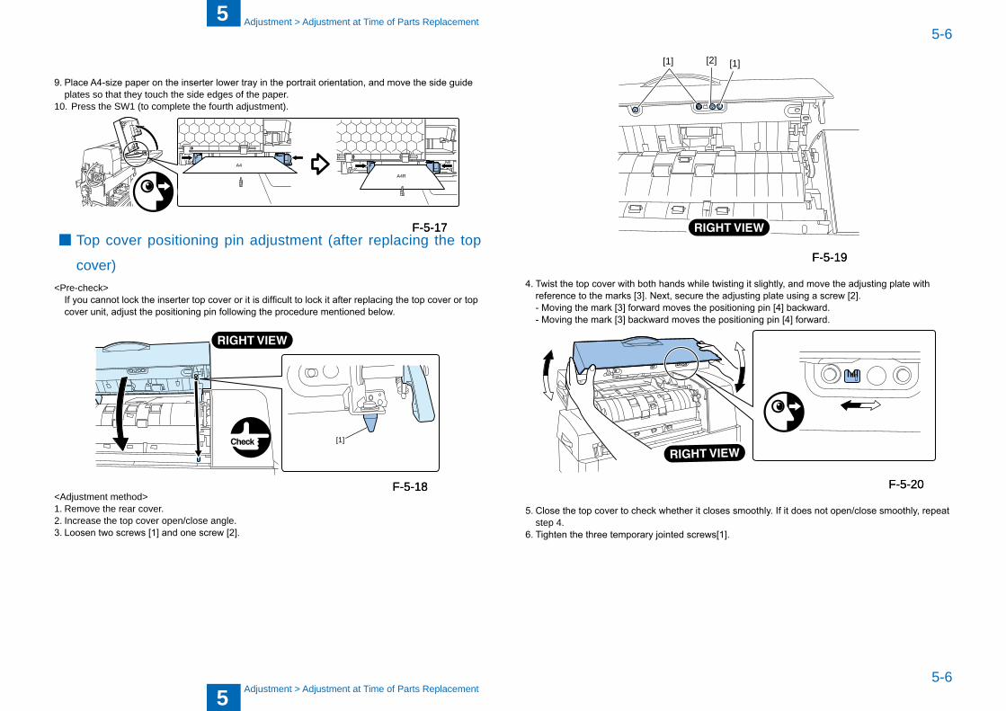
Document tray width adjustment (after replacing the document
width sensor)1. Remove the rear cover.2. Set the DIP switch as shown below, turn on the SW1 (push switch), and then turn on the
inserter.(Note: Keep pressing the SW1 for at least 2 seconds after turning on the power.)After switching between modes, turn off the power and then turn it on again.
DIPSW(■ ON□ OFF) Testmode1 2 3 4 5 6 7 8■ □ ■ □ □ □ □ □ Traycontroladjustment
LED1
SW3ON
1 2 3 4 5 6 7 8
SW1 SW2
LED2
3. Place A4-size paper on the inserter upper tray in the landscape orientation, and move the side guide plates so that they touch the side edges of the paper.
4. Press the SW1 (to complete the first adjustment).5. Place A4-size paper on the inserter upper tray in the portrait orientation, and move the side guide
plates so that they touch the side edges of the paper. 6. Press the SW1 (to complete the second adjustment).
A4 A4R
[1][1]
7. Place A4-size paper on the inserter lower tray in the landscape orientation, and move the side guide plates so that they touch the side edges of the paper.
8. Press the SW1 (to complete the third adjustment).
■
F-5-15F-5-15
F-5-16F-5-16
5
55-6
5-6
Adjustment > Adjustment at Time of Parts Replacement
Adjustment > Adjustment at Time of Parts Replacement
9. Place A4-size paper on the inserter lower tray in the portrait orientation, and move the side guide plates so that they touch the side edges of the paper.
10. Press the SW1 (to complete the fourth adjustment).
A4
A4R
Top cover positioning pin adjustment (after replacing the top
cover)<Pre-check> If you cannot lock the inserter top cover or it is difficult to lock it after replacing the top cover or top
cover unit, adjust the positioning pin following the procedure mentioned below.
[1]
<Adjustment method>1. Remove the rear cover. 2. Increase the top cover open/close angle. 3. Loosen two screws [1] and one screw [2].
■F-5-17F-5-17
F-5-18F-5-18
[1] [1][2]
4. Twist the top cover with both hands while twisting it slightly, and move the adjusting plate with reference to the marks [3]. Next, secure the adjusting plate using a screw [2].
- Moving the mark [3] forward moves the positioning pin [4] backward. - Moving the mark [3] backward moves the positioning pin [4] forward.
5. Close the top cover to check whether it closes smoothly. If it does not open/close smoothly, repeat step 4.
6. Tighten the three temporary jointed screws[1].
F-5-19F-5-19
F-5-20F-5-20
6 InstallationMaking Pre-installation ChecksC h e c k i n g B u n d l e d ComponentsUnpackingInstallation Procedure
■
■
■■
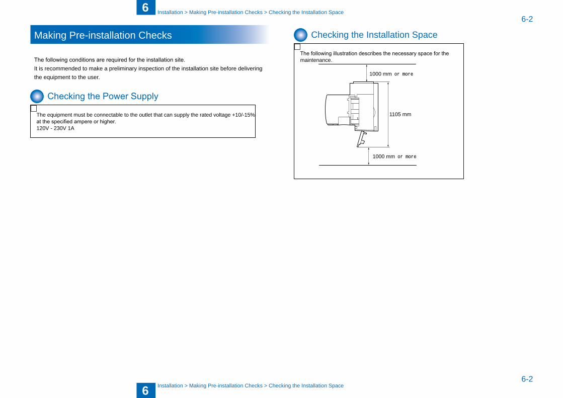
6
66-2
6-2
Installation > Making Pre-installation Checks > Checking the Installation Space
Installation > Making Pre-installation Checks > Checking the Installation Space
Making Pre-installation Checks
The following conditions are required for the installation site.It is recommended to make a preliminary inspection of the installation site �efore delivering the equipment to the user.
Checking the Power Supply
The equipment must �e connecta�le to the outlet that can supply the rated voltage +10/-15% at the specified ampere or higher.
120V - 230V 1A
Checking the Installation Space
The following illustration describes the necessary space for the maintenance.
1105 mm
1000 mm or more
1000 mm or more
6
66-3
6-3
Installation > Making Pre-installation Checks > Cautions at the Time of Installation
Installation > Making Pre-installation Checks > Cautions at the Time of Installation
Cautions at the Time of Installation
1. Turn off the host machine.
CAUTION
Before installing this equipment, be sure to perform the following steps in the specified order.
1) Turn OFF the main power switch of the host machine. 2) Be sure that the control panel display and the main power lamp are both turned OFF, and
then disconnect the power plug.
2. A�out the Installation This equipment is approx.55.0kg, so it should require two or more personnel to install.
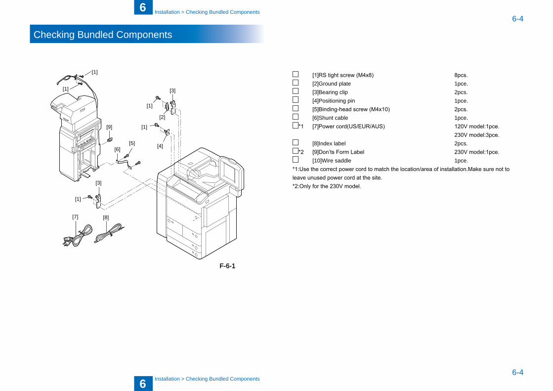
6
66-4
6-4
Installation > Checking Bundled Components
Installation > Checking Bundled Components
Checking Bundled Components
[3]
[1]
[1]
[1]
[7] [8]
[2]
[4][5][6]
[3]
[1]
[1]
[9]
F-6-1F-6-1
[1]RS tight screw (M4x8) 8pcs. [2]Ground plate 1pce. [3]Bearing clip 2pcs. [4]Positioning pin 1pce. [5]Binding-head screw (M4x10) 2pcs. [6]Shunt ca�le 1pce.*1 [7]Power cord(US/EUR/AUS) 120V model:1pce.
230V model:3pce. [8]Index la�el 2pcs.*2 [9]Don’ts Form Label 230V model:1pce. [10]Wire saddle 1pce.
*1:Use the correct power cord to match the location/area of installation.Make sure not to leave unused power cord at the site.*2:Only for the 230V model.

6
66-5
6-5
Installation > Unpacking > Unpacking Procedure
Installation > Unpacking > Unpacking Procedure
Unpacking
Unpacking Procedure
MEMOThe equipment ships, secured by tapes, cush-ioning and other materials to protect it from vi�ration and impact during transit. Remove all such tapes and cushioning materials as in-structed below before installing the equipment. (Keep all the shipping fixtures and cushion-ing materials in a safe place for later reuse in reshipping the equipment, as for relocation and repairs.)
1) Take out the accessory �ox from the package.
CAUTION
Leave the four cushioning materials attached to the inserter in position.
Removing the cushioning materials could result in a deformation of the mounting portion or elsewhere.
F-6-2F-6-2
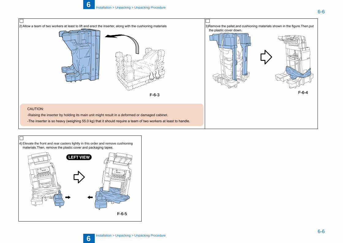
6
66-6
6-6
Installation > Unpacking > Unpacking Procedure
Installation > Unpacking > Unpacking Procedure
2) Allow a team of two workers at least to lift and erect the inserter, along with the cushioning materials
CAUTION:
-Raising the inserter �y holding its main unit might result in a deformed or damaged ca�inet.
-The inserter is so heavy (weighing 55.0 kg) that it should require a team of two workers at least to handle.
3)Remove the pallet,and cushioning materials shown in the figure.Then,put the plastic cover down.
4) Elevate the front and rear casters lightly in this order and remove cushioning materials.Then, remove the plastic cover and packaging tapes.
F-6-3F-6-3 F-6-4F-6-4
F-6-5F-6-5
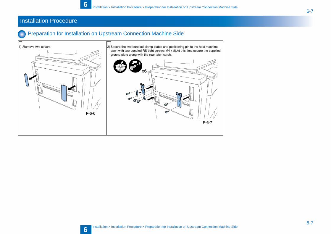
6
66-7
6-7
Installation > Installation Procedure > Preparation for Installation on Upstream Connection Machine Side
Installation > Installation Procedure > Preparation for Installation on Upstream Connection Machine Side
Installation Procedure
Preparation for Installation on Upstream Connection Machine Side
1) .Remove two covers. 2) Secure the two bundled clamp plates and positioning pin to the host machine each with two bundled RS tight screws(M4 x 8).At this time,secure the supplied ground plate along with the rear latch catch.
x6
F-6-6F-6-6
F-6-7F-6-7
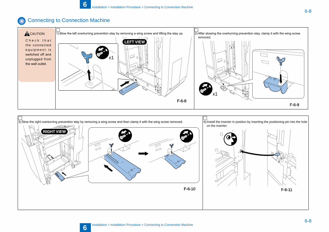
6
66-8
6-8
Installation > Installation Procedure > Connecting to Connection Machine
Installation > Installation Procedure > Connecting to Connection Machine
Connecting to Connection Machine
CAUTION
C h e c k t h a t the connected e q u i p m e n t i s switched off and unplugged from the wall outlet.
1) Stow the left overturning prevention stay by removing a wing screw and lifting the stay up.
x1
2) After stowing the overturning prevention stay, clamp it with the wing screw removed.
x1
3) Stow the right overturning prevention stay by removing a wing screw and then clamp it with the wing screw removed. 4) Install the inserter in position �y inserting the positioning pin into the hole on the inserter.
F-6-8F-6-8F-6-9F-6-9
F-6-10F-6-10 F-6-11F-6-11

6
66-9
6-9
Installation > Installation Procedure > Connecting to Connection Machine
Installation > Installation Procedure > Connecting to Connection Machine
5) With the Upper front cover open, remove one screw and press the lock lever to hook on the bearing clip. Reinstall the screw removed to secure the lock lever.
6) Close the Upper front cover.
F-6-12F-6-12
F-6-13F-6-13
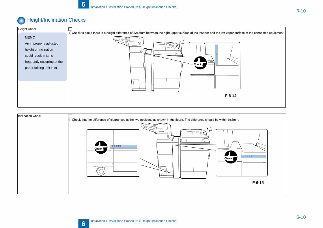
6
66-10
6-10
Installation > Installation Procedure > Height/Inclination Checks
Installation > Installation Procedure > Height/Inclination Checks
Height/Inclination ChecksHeight Check
MEMO
An improperly adjusted
height or inclination
could result in jams
frequently occurring at the
paper folding unit inlet.
1) Check to see if there is a height difference of 22±3mm between the right upper surface of the inserter and the left upper surface of the connected equipment.
Inclination Check1) Check that the difference of clearances at the two positions as shown in the figure. The difference should be within 0±2mm.
F-6-14F-6-14
F-6-15F-6-15
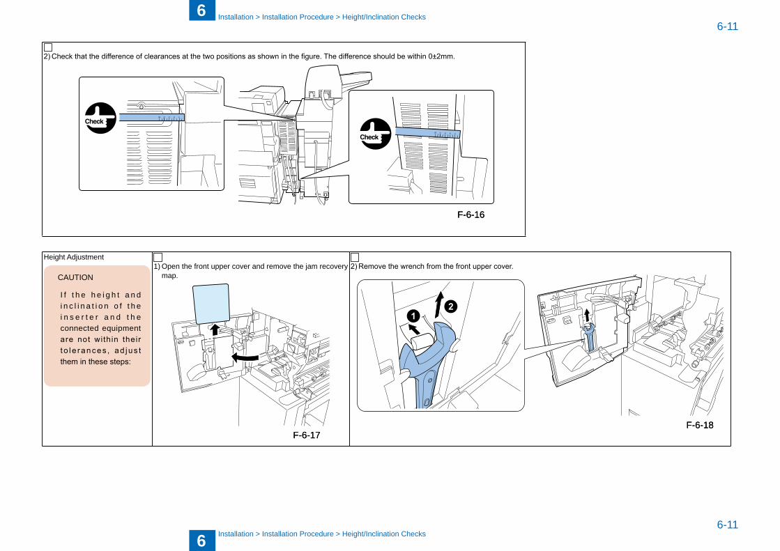
6
66-11
6-11
Installation > Installation Procedure > Height/Inclination Checks
Installation > Installation Procedure > Height/Inclination Checks
2) Check that the difference of clearances at the two positions as shown in the figure. The difference should be within 0±2mm.
Height Adjustment
CAUTION
I f t h e h e i g h t a n d i n c l i n a t i o n o f t h e i n s e r t e r a n d t h e connected equipment are not within their t o l e rances , ad jus t them in these steps:
1) Open the front upper cover and remove the jam recovery map.
2) Remove the wrench from the front upper cover.
F-6-16F-6-16
F-6-17F-6-17F-6-18F-6-18
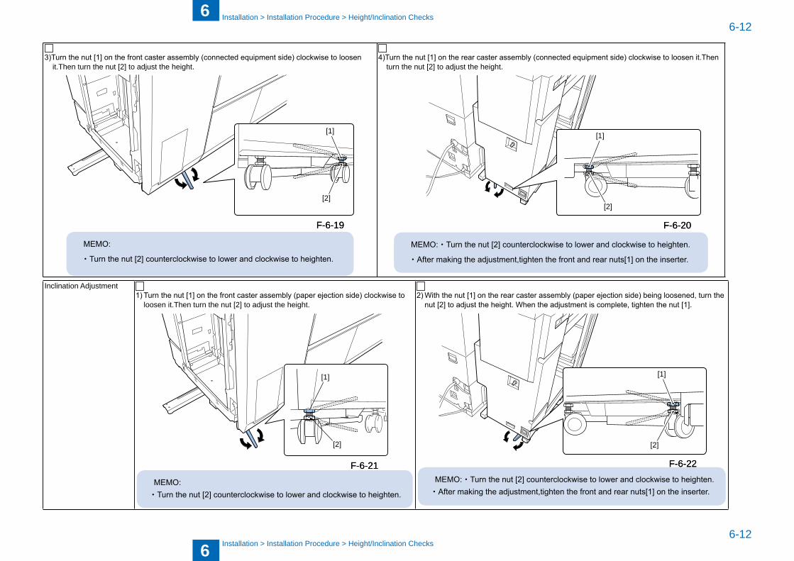
6
66-12
6-12
Installation > Installation Procedure > Height/Inclination Checks
Installation > Installation Procedure > Height/Inclination Checks
3)Turn the nut [1] on the front caster assembly (connected equipment side) clockwise to loosen it.Then turn the nut [2] to adjust the height.
[1]
[2]
MEMO:
・Turn the nut [2] counterclockwise to lower and clockwise to heighten.
4)Turn the nut [1] on the rear caster assembly (connected equipment side) clockwise to loosen it.Then turn the nut [2] to adjust the height.
[1]
[2]
MEMO:・Turn the nut [2] counterclockwise to lower and clockwise to heighten.
・After making the adjustment,tighten the front and rear nuts[1] on the inserter.
Inclination Adjustment1) Turn the nut [1] on the front caster assembly (paper ejection side) clockwise to
loosen it.Then turn the nut [2] to adjust the height.
[1]
[2]
MEMO:・Turn the nut [2] counterclockwise to lower and clockwise to heighten.
2) With the nut [1] on the rear caster assembly (paper ejection side) being loosened, turn the nut [2] to adjust the height. When the adjustment is complete, tighten the nut [1].
[1]
[2]
MEMO:・Turn the nut [2] counterclockwise to lower and clockwise to heighten.・After making the adjustment,tighten the front and rear nuts[1] on the inserter.
F-6-19F-6-19 F-6-20F-6-20
F-6-21F-6-21 F-6-22F-6-22
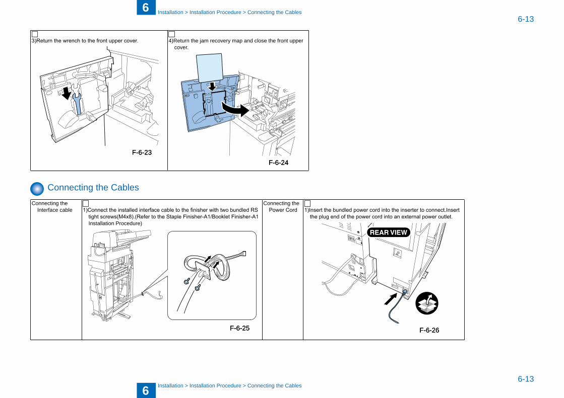
6
66-13
6-13
Installation > Installation Procedure > Connecting the Ca�les
Installation > Installation Procedure > Connecting the Ca�les
3)Return the wrench to the front upper cover. 4)Return the jam recovery map and close the front upper cover.
Connecting the Ca�lesConnecting the
Interface ca�le 1)Connect the installed interface cable to the finisher with two bundled RS tight screws(M4x8).(Refer to the Staple Finisher-A1/Booklet Finisher-A1 Installation Procedure)
Connecting the Power Cord 1)Insert the bundled power cord into the inserter to connect.Insert
the plug end of the power cord into an external power outlet.
F-6-23F-6-23F-6-24F-6-24
F-6-25F-6-25 F-6-26F-6-26
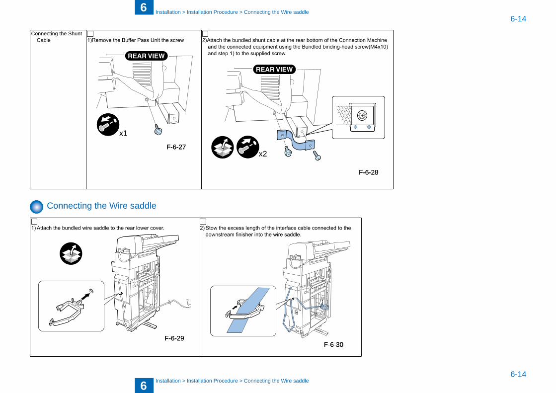
6
66-14
6-14
Installation > Installation Procedure > Connecting the Wire saddle
Installation > Installation Procedure > Connecting the Wire saddle
Connecting the Shunt Ca�le 1)Remove the Buffer Pass Unit the screw
x1
2)Attach the �undled shunt ca�le at the rear �ottom of the Connection Machine and the connected equipment using the Bundled binding-head screw(M4x10) and step 1) to the supplied screw.
x2
Connecting the Wire saddle
1) Attach the bundled wire saddle to the rear lower cover. 2) Stow the excess length of the interface cable connected to the downstream finisher into the wire saddle.
F-6-27F-6-27
F-6-28F-6-28
F-6-29F-6-29F-6-30F-6-30
6
66-15
6-15
Installation > Installation Procedure > Operation Checks
Installation > Installation Procedure > Operation Checks
Making Checks after Completion of Installation Work
Take back the following parts which are no longer necessary: [1]Cover of the Buffer Pass Unit 2pcs. [2]Power cord 2pcs.(230Vmodel) [3]Binding-head screw(M4x10) 1pce.
Operation Checks
1) After completion of installation, connect the power plug of the host machin and equipment to the power outlet. Then open the switch cover and turn ON the main power switch.
2) In the operation check mode, check for cover sheet insertion operation

7
7 Appendix
AppendixService ToolsGeneral Circuit Diagram
■■
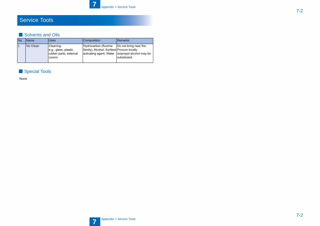
7
77-2
7-2
Appendix > Service Tools
Appendix > Service Tools
Service Tools
Solvents and OilsNo. Name Uses Composition Remarks
1 Vic Clean Cleaning:e.g., glass, plastic, rubber parts, external covers
Hydrocarbon (fluorine family), Alcohol, Surface activating agent, Water
Do not bring near fire.Procure locally.Isopropyl alcohol may �esu�stituted.
Special ToolsNone
■
■
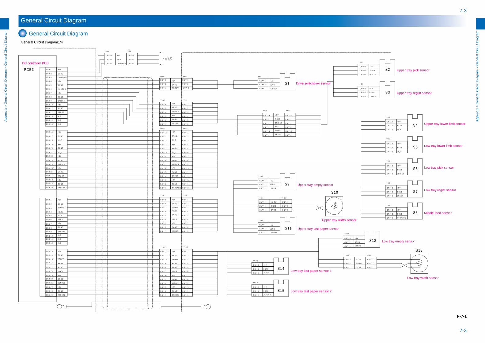
7-3
7-3
App
endi
x >
Gen
eral
Circ
uit D
iagr
am >
Gen
eral
Circ
uit D
iagr
am
App
endi
x >
Gen
eral
Circ
uit D
iagr
am >
Gen
eral
Circ
uit D
iagr
am
General Circuit Diagram
General Circuit DiagramGeneral Circuit Diagram1/4
Upper tray empty sensor
Low tray last paper sensor 2
+ 5 V
+ 3 . 3 V
S G N D
S G N D
2 E N D S 1
S G N D
T Y U K A N S
2 P I C K S
+ 5 V
S1
S6
S7
C N 9 - 9
S G N D
C N 9 - 1 0
C N 9 - 1 1
+ 5 V
C N 9 - 1 2
S G N D
C N 9 - 8
+ 5 V
2 L _ S
S G N D
2 R E G S
S G N D
+ 5 V
2 E N D S 2
S G N D
+ 5 V
S5
+ 5 V
2 V R S
S9
K U D O U S
S G N D
S11
C N 9 - 7
+ 5 V
2 E M P S
D F O P E N S
C N 9 - 6
C N 9 - 5
S G N D
+ 5 V
K U D O U S
S G N D
C N 9 - 4
C N 9 - 3
C N 9 - 2
C N 9 - 1
+ 5 V
S8
C N 9 - 1 3 N . C
N . C
N . C
C N * * - 3
C N * * - 1
C N * * - 4
C N * * - 6
C N * * - 2
C N * * - 5
C N 9 - 1 4
C N 9 - 1 5
C N 9 - 1 8
C N 9 - 3 0
C N 9 - 2 2
C N 9 - 2 6
C N 9 - 2 7
C N 9 - 1 7
C N 9 - 2 3
C N 9 - 2 8
C N 9 - 2 1
C N 9 - 2 4
C N 9 - 1 6
C N 9 - 2 5
C N 9 - 2 0
C N 9 - 2 9
C N 9 - 1 9
+ 5 V
S G N D
1 P I C K S
+ 5 V
1 R E G S
S G N D
S G N D
1 L - S
+ 5 V
C N 8 - 3
C N 8 - 1 5
C N 8 - 7
C N 8 - 1 1
C N 8 - 1 2
C N 8 - 2
C N 8 - 8
C N 8 - 1 3
C N 8 - 6
C N 8 - 9
C N 8 - 2 0
C N 8 - 2 1
C N 8 - 1
C N 8 - 1 0
C N 8 - 1 8
C N 8 - 5
C N 8 - 2 4
C N 8 - 1 7
C N 8 - 1 4
C N 8 - 4
C N 8 - 1 9
C N 8 - 1 6
C N 8 - 2 3
C N 8 - 2 2
+ 5 V
1 E N D S 1
1 E M P S
S G N D
S G N D
+ 5 V
S G N D
1 V R S
+ 3 . 3 V
N . C
N . C
N . C
D F O P E N S
S G N D
S G N D
S G N D
+ 5 V
+ 5 V
+ 5 V
1 R E G S
S G N D
+ 5 V
1 P I C K S
K U D O U C N * * - 3
C N * * - 2
C N * * - 1
S G N D
C N * * - 1
C N * * - 2
C N * * - 3
C N * * - 2
C N * * - 3
C N * * - 1 1 P I C K S
+ 5 V
C N * * - 2 S G N D
C N * * - 1
C N * * - 3 + 5 V
1 R E G S
C N * * - 9
C N * * - 1 0
C N * * - 3
C N * * - 1 4
C N * * - 2
C N * * - 1 3
C N * * - 1 5
C N * * - 5
C N * * - 7
C N * * - 4
C N * * - 1 1
C N * * - 1
C N * * - 6
C N * * - 8
C N * * - 1 2
+ 5 V
2 L _ S
2 R E G S
S G N D
2 P I C K S
+ 5 V
S G N D
1 L - S
S G N D
T Y U K A N S
S G N D
+ 5 V
+ 5 V
+ 5 V
S G N D
C N * * - 3
C N * * - 1 5
C N * * - 1 4
C N * * - 1
C N * * - 5
C N * * - 2
C N * * - 7
C N * * - 9
C N * * - 8
C N * * - 4
C N * * - 1 0
C N * * - 6
C N * * - 1 1
C N * * - 1 3
C N * * - 1 2
S G N D
C N * * - 1
S G N DC N * * - 2
C N * * - 3
C N * * - 3
C N * * - 2
C N * * - 1
+ 5 V
C N * * - 1
C N * * - 2
C N * * - 3
S G N D
S G N D
+ 5 V
C N * * - 1
C N * * - 3 + 5 V
+ 5 V
C N * * - 2
S G N D
+ 5 V
C N * * - 2
C N * * - 3
C N * * - 1
2 P I C K S
2 L _ S
T Y U K A N S
1 L - S
2 R E G S
S3
S2
S4
C N * * - 9
C N * * - 3
C N * * - 2
C N * * - 5
C N * * - 7
C N * * - 4
C N * * - 1
C N * * - 6
C N * * - 8
+ 3 . 3 V
+ 5 V
S G N D
S G N D
+ 5 V
S G N D
C N * * - 6
C N * * - 9
C N * * - 5
C N * * - 4
C N * * - 2
C N * * - 8
C N * * - 3
C N * * - 1
C N * * - 7
C N * * - 2
C N * * - 1
C N * * - 2
C N * * - 3
S G N D
S G N D
C N * * - 1
C N * * - 3 + 5 V
+ 5 V
1 E M P S
1 E N D S 1
1 V R S
+ 3 . 3 V
S10
S G N D
C N * * - 1
C N * * - 2
C N * * - 3
C N * * - 3
C N * * - 1
C N * * - 2
C N * * - 2
C N * * - 1
+ 5 V
+ 5 V
S G N D
C N * * - 2 S G N D
+ 3 . 3 V
S12
C N * * - 1 2 E N D S 1
2 E M P S
2 V R S
S G N D
C N * * - 3
S14C N * * - 3
C N * * - 1
S13
C N * * - 2
C N * * - 3C N * * - 1
C N * * - 3
C N * * - 2
S G N D
C N * * - 1
+ 5 V
C N * * - 2 S152 E N D S 2
C N * * - 3
C N * * - 2
C N * * - 3
C N * * - 6
C N * * - 9
C N * * - 1 0
C N * * - 5
C N * * - 4
C N * * - 1 1
C N * * - 2
C N * * - 8
C N * * - 1 2
C N * * - 3
C N * * - 5
C N * * - 1
C N * * - 7
C N * * - 7
C N * * - 4
C N * * - 1 1
C N * * - 1
C N * * - 6
C N * * - 8
C N * * - 1 2
C N * * - 1 0
C N * * - 9
2 E M P S
+ 5 V
S G N D
2 V R S
S G N D
2 E N D S 2
S G N D
S G N D
+ 5 V
+ 5 V
+ 3 . 3 V
2 E N D S 1
1 E N D S 1
1 E M P S
1 V R S
C N * * - 1
C N * * - 2
C N * * - 3
C N * * - 1
C N * * - 5
C N * * - 6
C N * * - 2
C N * * - 4
C N * * - 3
C N * * - 4
+ 5 V C N * * - 4
+ 5 V 1-**NC6-**NC
S G N D
1 P I C K S C N * * - 3
1 R E G S
5-**NC2-**NC S G N D
C N * * - 3
C N * * - 5
C N * * - 6C N * * - 1
C N * * - 2
C N * * - 3
C N * * - 2
C N * * - 1
C N * * - 1
C N * * - 2
C N * * - 3
A
PCB3
DC controller PCB
Drive switchover sensor
Upper tray pick sensor
Upper tray regist sensor
Upper tray lower limit sensor
Low tray lower limit sensor
Low tray pick sensor
Low tray regist sensor
Middle feed sensor
Low tray last paper sensor 1
Upper tray width sensor
Upper tray last paper sensor
Low tray empty sensor
Low tray width sensor
* *=48 * *=49
* *=50 * *=51
* *=52
* *=53
* *=54 * *=55
* *=56
* *=57
* *=58
* *=59
* *=60
* *=61 * *=62
* *=63
* *=64 * *=65
* *=69
* *=164 * *=165
* *=169
* *=166
* *=167 * *=168
* *=170
to
* *=43 * *=44
* *=45 * *=46 * *=47
F-7-1F-7-1
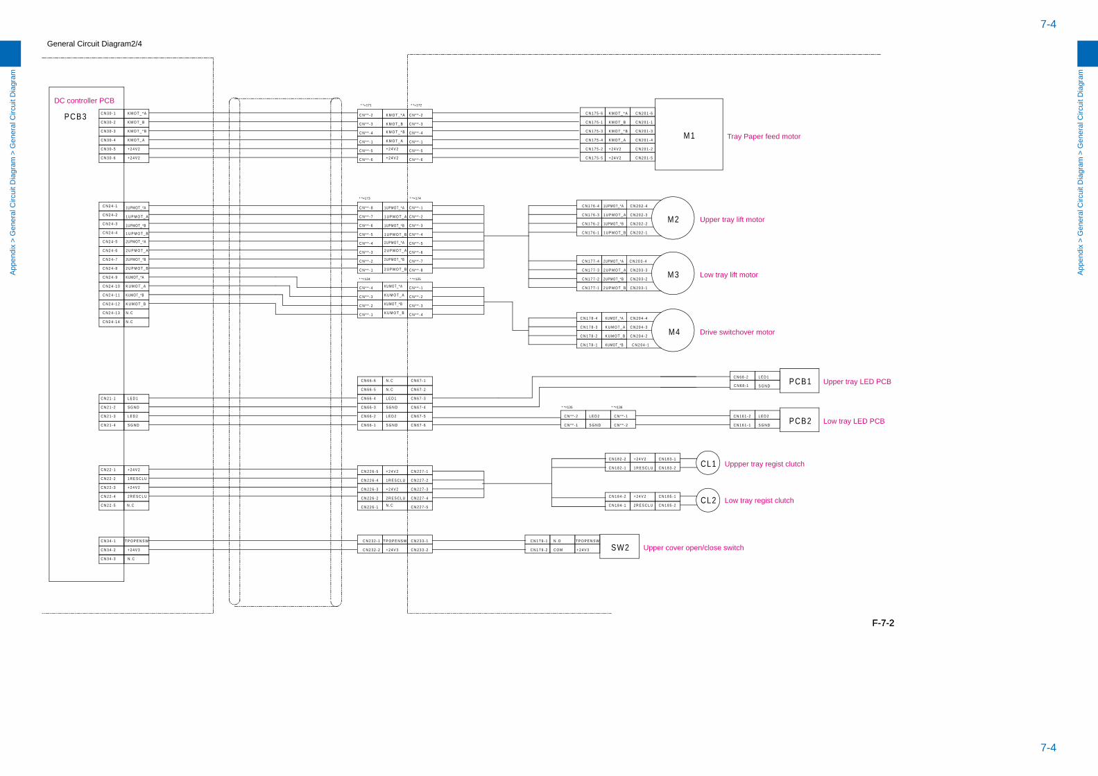
7-4
7-4
App
endi
x >
Gen
eral
Circ
uit D
iagr
am >
Gen
eral
Circ
uit D
iagr
am
App
endi
x >
Gen
eral
Circ
uit D
iagr
am >
Gen
eral
Circ
uit D
iagr
am
General Circuit Diagram2/4
K M O T _ BC N 3 0 - 2
1UPMOT_*A
C N 1 7 5 - 6K M O T _ * A
K M O T _ * B
K M O T _ * A
+ 2 4 V 2
C N 3 0 - 3
C N 3 0 - 5
M2
K M O T _ A
1 U P M O T _ BC N 2 4 - 4
C N 3 0 - 6
K M O T _ A
1UPMOT_*BC N 2 4 - 3
K M O T _ * B
C N 3 0 - 1
+ 2 4 V 2 C N 1 7 5 - 5
C N 1 7 5 - 3
K M O T _ B
+ 2 4 V 2
1 U P M O T _ A
C N 1 7 5 - 4C N 3 0 - 4
+ 2 4 V 2
C N 2 4 - 1
C N 2 4 - 2
C N 1 7 5 - 2
C N 1 7 5 - 1
C N 2 4 - 5
C N 2 4 - 8
C N 2 4 - 6
C N 2 4 - 7
C N 2 4 - 1 2
C N 2 4 - 9
C N 2 4 - 1 1
C N 2 4 - 1 0
2UPMOT_*A
2UPMOT_*BM3
2 U P M O T _ A
2 U P M O T _ B
M4
N . C
C N 2 4 - 1 4
C N 2 4 - 1 3
N . C
C N 2 0 1 - 4
C N 2 0 1 - 1
C N 2 0 1 - 3
C N 2 0 1 - 6
C N 2 0 1 - 2
C N 2 0 1 - 5
C N 1 7 6 - 1
C N 1 7 6 - 2
C N 1 7 6 - 4
C N 1 7 6 - 3
C N 2 0 2 - 4
C N 2 0 2 - 3
C N 2 0 2 - 2
C N 2 0 2 - 1
C N 1 7 7 - 1
C N 1 7 7 - 2
C N 1 7 7 - 3
C N 1 7 7 - 4 C N 2 0 3 - 4
C N 2 0 3 - 3
C N 2 0 3 - 2
C N 2 0 3 - 1
C N 1 7 8 - 3
C N 1 7 8 - 2
C N 1 7 8 - 1
C N 1 7 8 - 4
K U M O T _ A
KUMOT_*A
KUMOT_*B
K U M O T _ B
C N 2 0 4 - 4
C N 2 0 4 - 3
C N 2 0 4 - 2
C N 2 0 4 - 1
2UPMOT_*B
1UPMOT_*B
K U M O T _ B
2 U P M O T _ B
1 U P M O T _ A
KUMOT_*A
2UPMOT_*A
1 U P M O T _ B
K U M O T _ A
2 U P M O T _ A
KUMOT_*B
1UPMOT_*A
+ 2 4 V 2
+ 2 4 V 2
C N * * - 1
C N * * - 5
C N * * - 6
C N * * - 2
C N * * - 4
C N * * - 3
C N * * - 1
C N * * - 5
C N * * - 6
C N * * - 7
C N * * - 2
C N * * - 8
C N * * - 4
C N * * - 3
C N * * - 7
C N * * - 6
C N * * - 1
C N * * - 8
C N * * - 5
C N * * - 3
C N * * - 4
C N * * - 2
C N * * - 2
C N * * - 1
C N * * - 4
C N * * - 3
C N * * - 1
C N * * - 3
C N * * - 4
C N * * - 2
2UPMOT_*B
1 U P M O T _ A
2 U P M O T _ A
1UPMOT_*B
2UPMOT_*A
2 U P M O T _ B
1 U P M O T _ B
1UPMOT_*A
K U M O T _ A
KUMOT_*A
K U M O T _ B
KUMOT_*B
C N 6 7 - 4
C N 3 4 - 1
C N 1 8 3 - 1
S G N D
C N 2 3 3 - 2
C N 2 1 - 4
C N 1 8 4 - 2
L E D 2
C N 2 3 3 - 1
C N 1 8 2 - 1
C N 6 7 - 2
C N 2 2 6 - 3
C N 1 8 5 - 2
+ 2 4 V 2 C N 2 2 7 - 1
C N 2 2 - 4
L E D 1
T P O P E N S W
C N 1 6 1 - 1
CL1
CL2
C N 6 6 - 3
C N 2 2 6 - 2
C N 3 4 - 2
L E D 1
C N 1 7 9 - 1
C N 6 7 - 1
+ 2 4 V 2
C N 1 8 5 - 1
C N 2 3 2 - 2
C N 6 8 - 2
N . C
C N 1 6 1 - 2L E D 2
C N 2 2 - 1
1 R E S C L UC N 2 2 - 2
C N 1 8 3 - 2
S G N D
2 R E S C L U
C N 2 2 6 - 1
C N 2 2 7 - 4
C N 2 1 - 3
+ 2 4 V 2
C N 1 7 9 - 2
1 R E S C L U
SW2
C N 6 6 - 1
C N 1 8 2 - 2
1 R E S C L U
C N 2 3 2 - 1
S G N D
+ 2 4 V 3
C N 2 2 - 3 C N 2 2 7 - 3
L E D 2
C O M + 2 4 V 3
T P O P E N S W
C N 2 1 - 1 C N 6 6 - 4
C N 6 6 - 2
S G N D
C N 6 7 - 3
+ 2 4 V 2
+ 2 4 V 2
C N 2 2 7 - 2
T P O P E N S W
C N 3 4 - 3
C N 2 2 6 - 4
C N 2 1 - 2
N . O
C N 1 8 4 - 1
L E D 1
+ 2 4 V 2
S G N D
2 R E S C L U
S G N D
2 R E S C L U
+ 2 4 V 3
C N 2 2 - 5 N . C N . C
C N 2 2 6 - 5
C N 2 2 7 - 5
K M O T _ A
K M O T _ B
K M O T _ * B
K M O T _ * A
C N * * - 6
C N * * - 5
C N * * - 3
C N * * - 1
C N * * - 4
C N * * - 2
C N 6 6 - 5
C N 6 6 - 6
N . C
N . C
C N 6 7 - 6
C N 6 7 - 5 C N * * - 1L E D 2
C N * * - 2S G N D
C N * * - 2
C N * * - 1
PCB1
PCB2
PCB3
C N 6 8 - 1
M1
DC controller PCB
Tray Paper feed motor
Upper tray lift motor
Low tray lift motor
Drive switchover motor
Upper tray LED PCB
Low tray LED PCB
Uppper tray regist clutch
Low tray regist clutch
Upper cover open/close switch
* *=171 * *=172
* *=173 * *=174
* *=124 * *=125
* *=135 * *=136
F-7-2F-7-2
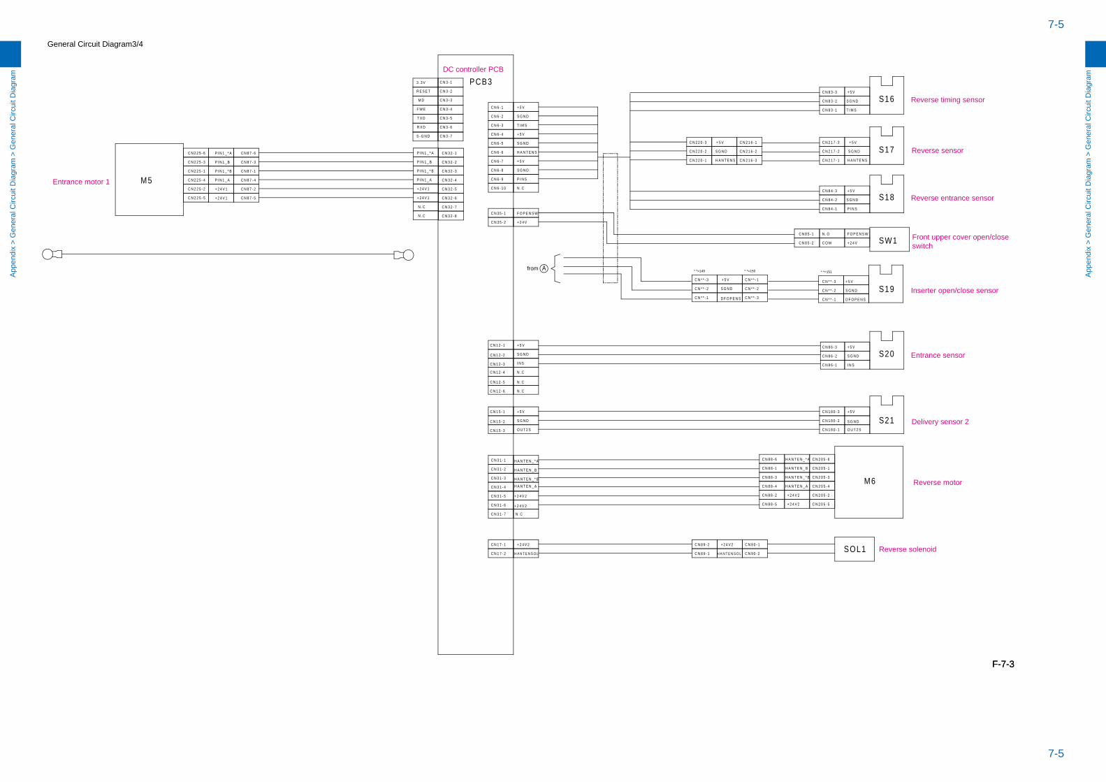
7-5
7-5
App
endi
x >
Gen
eral
Circ
uit D
iagr
am >
Gen
eral
Circ
uit D
iagr
am
App
endi
x >
Gen
eral
Circ
uit D
iagr
am >
Gen
eral
Circ
uit D
iagr
am
General Circuit Diagram3/4
C N 3 1 - 4
C N 3 2 - 5
C N 2 2 5 - 6
+ 2 4 V 2
SW1
P I N S
A
C N 8 8 - 3
C N 8 7 - 1
T I M S
C N 1 2 - 3
C N 3 2 - 7
H A N T E N _ A
+ 2 4 V 2
C N 2 2 5 - 5
C N 3 2 - 2
C N 2 1 6 - 2
C N 3 2 - 3
C N 1 2 - 1
P I N 1 _ A
H A N T E N _ B
C N 3 - 7
+ 2 4 V 2
C N 3 5 - 2
N . C
C N 1 2 - 6
+ 2 4 V
C N 2 1 6 - 1
C N 8 3 - 2
I N S
C N 6 - 7
S G N D
F W E
+ 2 4 V 1
+ 2 4 V 2
H A N T E N S O LC N 1 7 - 2
N . C
+ 2 4 V 1
+ 5 V
C N 3 5 - 1
C N 3 - 6
P I N 1 _ A
C O M
+ 5 V
S G N D
S G N D
S18
C N 3 - 3
N . C
T I M S
C N 2 1 7 - 3
C N 8 4 - 1
+ 5 V
C N 8 6 - 1
C N 8 8 - 5
C N 8 3 - 3
+ 5 V
C N 3 - 5
+ 5 V
N . O
P I N 1 _ * A
+ 2 4 V 2
F O P E N S W
S20
+ 2 4 V
C N 2 1 7 - 2
M5
R E S E T + 5 V
C N 3 2 - 6
P I N 1 _ B
C N 3 2 - 1
N . C
S G N D
C N 8 6 - 3
P I N 1 _ B
M D S16
C N 3 2 - 8
C N 3 1 - 1
S G N D
N . C
C N 3 2 - 4
C N 3 1 - 6
+ 5 V
C N 1 8 0 - 3
C N * * - 1
H A N T E N SC N 8 7 - 3
H A N T E N S O L
C N 3 - 2
C N 6 - 1
C N * * - 2
C N 9 0 - 1
C N 1 2 - 5
+ 2 4 V 1
C N 9 0 - 2
C N 1 8 0 - 1
S G N D
P I N 1 _ * B
+ 5 V
C N 6 - 6
+ 5 V
P I N 1 _ * B
C N 6 - 3
S G N D
C N 8 6 - 2
C N 6 - 2
H A N T E N _ * A
S G N D
C N 3 1 - 2
C N 2 1 6 - 3
C N * * - 3
C N 8 4 - 3
S - G N D
C N 2 0 5 - 1
C N 8 9 - 1
C N 1 8 0 - 2
I N S
C N 2 1 7 - 1
+ 2 4 V 1
C N * * - 1
C N 3 - 1
C N 2 2 0 - 1
C N 2 0 5 - 4C N 8 8 - 4
O U T 2 S
D F O P E N SC N * * - 3
C N 6 - 9
T X D
C N 1 5 - 3
C N 2 0 5 - 2
C N 8 5 - 1
C N 3 1 - 3
S G N D
C N 8 7 - 4
C N 3 1 - 7
C N 1 5 - 1
C N * * - 1
R X D
C N 2 0 5 - 5
P I N 1 _ * A
C N 1 2 - 4
+ 5 V
F O P E N S W
H A N T E N _ * B
N . C
C N 6 - 5
M6
C N * * - 3
C N 8 7 - 6
C N 3 - 4
C N 2 0 5 - 6
S G N D
C N 3 1 - 5
O U T 2 S
H A N T E N _ A
N . C
SOL1
C N * * - 2
H A N T E N S
H A N T E N S
C N 2 2 5 - 2
C N 2 0 5 - 3
S G N D
S G N D
C N * * - 2
C N 6 - 8
C N 8 7 - 2
S21
H A N T E N _ * A
S19
C N 8 7 - 5
S17C N 2 2 5 - 3
C N 8 3 - 1
D F O P E N S
C N 8 9 - 2
C N 6 - 4
C N 1 5 - 2
C N 2 2 0 - 2
+ 5 V
H A N T E N _ B C N 8 8 - 1
C N 2 2 5 - 1
C N 1 7 - 1
C N 6 - 1 0
C N 8 8 - 6
C N 8 8 - 2
+ 2 4 V 2
C N 2 2 0 - 3
C N 8 4 - 2
H A N T E N _ * B
C N 2 2 5 - 4
+ 5 V
P I N S
C N 8 5 - 2
C N 1 2 - 2
+ 5 V
S G N D
PCB33 . 3 V
Entrance motor 1
DC controller PCB
Reverse timing sensor
Reverse sensor
Reverse entrance sensor
Front upper cover open/close switch
Inserter open/close sensor
Entrance sensor
Delivery sensor 2
Reverse motor
Reverse solenoid
from * *=149 * *=150 * *=151
F-7-3F-7-3
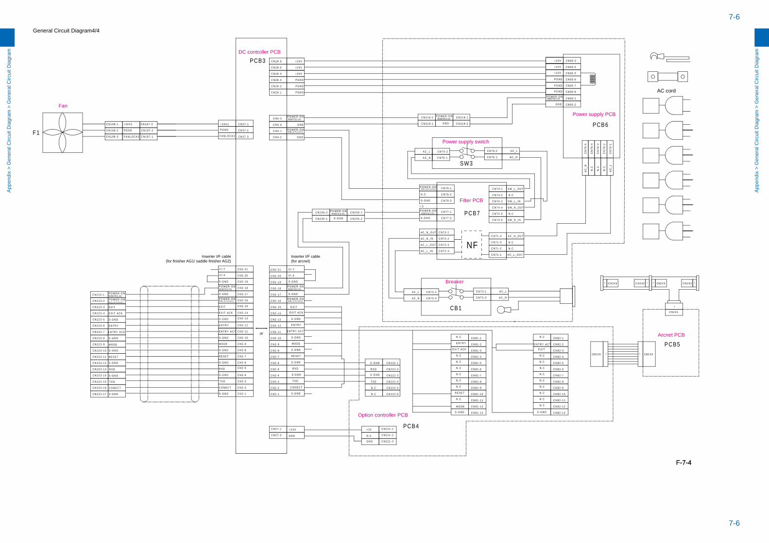
7-6
7-6
App
endi
x >
Gen
eral
Circ
uit D
iagr
am >
Gen
eral
Circ
uit D
iagr
am
App
endi
x >
Gen
eral
Circ
uit D
iagr
am >
Gen
eral
Circ
uit D
iagr
am
General Circuit Diagram4/4
M O D E
P O W E R - O N C N 2 - 1 6
E X I T
R E S E T
E N T R Y A C T
S - G N D
C O N E C T
C N 2 - 1 7
C N 2 - 1 2
R X D
C N 2 - 8
C N 2 - 7
E N T R Y
C N 2 - 6
C N 2 - 1 4
C N 2 - 3
C N 2 - 2
C N 2 - 9
E X I T A C K
S - G N D
C N 2 - 1 1
C N 2 - 4
T X D
C N 2 - 1S - G N D
S - G N D
C N 2 - 1 0S - G N D
S - G N D
S - G N D
C N 2 2 2 - 5
E N T R Y
C N 2 2 2 - 1
A C _ L
C N 7 2 - 1
C N 7 3 - 2
A C _ N _ O U T
S - G N D
T X D
C N 7 3 - 3
C N 2 2 2 - 3
R E S E T
C N 2 2 2 - 4
C N 7 1 - 3
C N 2 2 2 - 6
S - G N D
E N T R Y A C T
C N 4 - 4
S - G N D
C N 2 8 - 5
R X D
C N 2 8 - 6
S - G N D
N . C
C N 7 3 - 4
C N 4 - 3
N . C
R X D
M O D E
C N 2 8 - 4
S - G N D
A C _ N
S - G N D
C N 7 1 - 4A C _ N _ I N
E X I T A C K
A C _ L
C N 7 2 - 2
C N 2 8 - 2
S - G N D
T X D
C N 7 3 - 1
C N 2 8 - 3
C N 2 8 - 1
P O W E R - O NC N 4 - 1
G N D
NF
C N 2 2 2 - 2
A C _ N
N.C
N.C
N.C
AC
_L
AC
_N
C N 7 7 - 1
C N 7 7 - 2
A C _ N
A C _ L C N 7 5 - 2 A C _ L
C N 7 5 - 1
C N 7 6 - 2
C N 7 6 - 1 A C _ N
E X I T
C O N E C T
S - G N D
CN
78-3
CN
78-4
CN
78-5
CN
78-2
CN
78-1
C N 8 0 - 6
C N 8 0 - 4
C N 8 0 - 5
C N 8 0 - 3
C N 8 0 - 1
C N 8 0 - 2
+ 2 4 V
+ 2 4 V
+ 2 4 V
C N 2 1 9 - 1
C N 2 1 9 - 2 C N 2 1 8 - 1
C N 2 1 8 - 2
G N D
G N D
C N 2 7 - 1
C N 2 7 - 2 G N D
+ 2 4 V
G N D
C N 2 2 1 - 2
C N 2 2 1 - 3
C N 2 2 1 - 1+ 2 4
N . C
C N 8 1 - 1
E X I TE X I T A C K
S - G N D
E N T R Y E N T R Y A C T
M O D E
R E S E T
N . C
N . C
N . C
N . C
N . C
N . C
N . C
N . C
N . C
N . C
N . C
N . C
N . C
N . C
N . C
N . C
N . C
N . C
P G N D
+ 2 4 V
+ 2 4 V
P G N D
P G N D
P G N D
+ 2 4 V
P G N D
P G N D
S - G N D
C N 7 2 - 3
A C _ L _ I NC N 7 1 - 1
C N 7 1 - 2
A C _ L _ O U T
N . C
N . C
C N 8 1 - 2
C N 8 1 - 3
C N 8 1 - 4
C N 8 1 - 5
C N 8 1 - 6
C N 8 1 - 7
C N 8 1 - 8
C N 8 1 - 9
C N 8 1 - 1 0
C N 8 1 - 1 1
C N 8 1 - 1 2
C N 8 1 - 1 3
C N 8 2 - 1
C N 8 2 - 2
C N 8 2 - 3
C N 8 2 - 4
C N 8 2 - 5
C N 8 2 - 6
C N 8 2 - 7
C N 8 2 - 8
C N 8 2 - 9
C N 8 2 - 1 0
C N 8 2 - 1 1
C N 8 2 - 1 2
C N 8 2 - 1 3
C N 2 3 5 - 1C N 2 3 6 - 2
C N 2 3 5 - 2C N 2 3 6 - 1 S - G N D
C N 8 0 - 8
C N 8 0 - 7
S - G N D
M O D E
C O N E C T
T X D
P O W E R - O N
E N T R Y A C K
E N T R Y
R E S E T
E X I T
S - G N D
S - G N D
S - G N D
R X D
S - G N D
E X I T A C K
S - G N D
C N 2 2 3 - 1
C N 4 - 2 G N D
S - G N D
C N 2 - 1 8
C N 2 - 1 9
C N 2 - 2 0
C N 2 - 2 1
S - G N D
C N 2 - 2 1
S - G N D
REMOTE(3.3V)
P O W E R - O N
S - G N D
C N 7 2 - 4
A C _ N _ O U T
A C _ L _ O U T
C N 7 4 - 1
C N 7 4 - 2
C N 7 4 - 4
C N 7 4 - 3
C N 7 4 - 6
C N 7 4 - 5
S W _ L _ O U T
N . C
S W _ L _ I N
N . C
S W _ N _ I N
S W _ N _ O U T
C N 7 9 - 1
C N 7 9 - 2N . C
S - G N D C N 7 9 - 3
P O W E R - O N
2
R E L A Y ( 2 4 V )
P O W E R - O NP O W E R - O NREMOTE(3.3V)
R E L A Y ( 2 4 V )
P O W E R - O NREMOTE(3.3V)
R E L A Y ( 2 4 V )
P O W E R - O NREMOTE(3.3V) REMOTE(3.3V)
P O W E R - O N
P O W E R - O N
R E L A Y ( 2 4 V )
REMOTE(3.3V)P O W E R - O N
REMOTE(3.3V)
P O W E R - O NREMOTE(3.3V)
R E L A Y ( 2 4 V )
C N 1 9 8 - 3F1 P G N DC N 1 9 8 - 2 C N 1 9 7 - 2
C N 1 9 8 - 1 C N 1 9 7 - 3
C N 1 9 7 - 1
+ 2 4 V 1
F A N L O C K 3 C N 3 7 - 3
C N 3 7 - 1
C N 3 7 - 2
+ 2 4 V 1
F A N L O C K 3
P G N D
SW3
CB1
C N 2 - 2 0
C N 2 - 1 9
C N 2 - 1 8
C N 2 - 1 7
C N 2 - 1 6
C N 2 - 1 5
C N 2 - 1 4
C N 2 - 1 3
C N 2 - 1 2
C N 2 - 1 1
C N 2 - 1 0
C N 2 - 9
C N 2 - 8
C N 2 - 7
C N 2 - 6
C N 2 - 5
C N 2 - 4
C N 2 - 3
C N 2 - 2
C N 2 - 1
C N 2 2 3 - 2
C N 2 2 3 - 3
C N 2 2 3 - 4
C N 2 2 3 - 5
C N 2 2 3 - 6
C N 2 2 3 - 7
C N 2 2 3 - 8
C N 2 2 3 - 9
C N 2 2 3 - 1 0
C N 2 2 3 - 1 1
C N 2 2 3 - 1 2
C N 2 2 3 - 1 3
C N 2 2 3 - 1 4
C N 2 2 3 - 1 5
C N 2 2 3 - 1 6
C N 2 2 3 - 1 7
PCB4
PCB6
PCB7
042NC*932NC *
C N 2 4 1
PCB5
*
C N 2 4 4C N 2 4 5 342NC** ** C N 2 4 2
PCB3
AC cord
C N 2 - 1 5
C N 2 - 1 3
C N 2 - 5
Power supply switch
Filter PCB
Breaker
Option controller PCB
Arcnet PCB
Power supply PCB
V I - Y V I - Y
V I - X V I - X
or
Inserter I/F cable(for arcnet)
Fan
DC controller PCB
Inserter I/F cable(for finisher AG1/ saddle finisher AG2)
F-7-4F-7-4