paper deck unit-b2 service manual - canon...
TRANSCRIPT

654321
Paper Deck Unit-B2
Service Manual
September 9, 2013Revision 2

0
00-2
0-2
ApplicationThis manual has been issued by Canon Inc. for qualified persons to learn technical theory, installation, maintenance, and repair of products. This manual covers all localities where the products are sold. For this reason, there may be information in this manual that does not apply to your locality.
CorrectionsThis manual may contain technical inaccuracies or typographical errors due to improvements or changes in products. When changes occur in applicable products or in the contents of this manual, Canon will release technical information as the need arises. In the event of major changes in the contents of this manual over a long or short period, Canon will issue a new edition of this manual.
The following paragraph does not apply to any countries where such provisions are inconsistent with local law.
TrademarksThe product names and company names used in this manual are the registered trademarks of the individual companies.
CopyrightThis manual is copyrighted with all rights reserved. Under the copyright laws, this manual may not be copied, reproduced or translated into another language, in whole or in part, without the consent of Canon Inc.
© CANON INC. 2013
CautionUse of this manual should be strictly supervised to avoid disclosure of confidential information.

0
00-3
0-3
Explanation of SymbolsThe following symbols are used throughout this Service Manual.
Symbols Explanation Symbols Explanation
Check Remove the claw.
Check visually. Insert the claw.
Check the noise. Use the bundled part.
Disconnect the connector. Push the part.
Connect the connector. Plug the power cable.
Remove the cable/wire from the cable guide or wire saddle.
Turn on the power.
Set the cable/wire to the cable guide or wire saddle.
Remove the screw.
Tighten the screw.
The following rules apply throughout this Service Manual:
1. Each chapter contains sections explaining the purpose of specific functions and the relationship between electrical and mechanical systems with reference to the timing of operation.
In the diagrams, represents the path of mechanical drive; where a signal name accompanies the symbol, the arrow indicates the direction of the electric signal. The expression "turn on the power" means flipping on the power switch, closing the front door, and closing the delivery unit door, which results in supplying the machine with power.
2. In the digital circuits, '1' is used to indicate that the voltage level of a given signal is "High", while '0' is used to indicate "Low". (The voltage value, however, differs from circuit to circuit.) In addition, the asterisk (*) as in "DRMD*" indicates that the DRMD signal goes on when '0'.
In practically all cases, the internal mechanisms of a microprocessor cannot be checked in the field. Therefore, the operations of the microprocessors used in the machines are not discussed: they are explained in terms of from sensors to the input of the DC controller PCB and from the output of the DC controller PCB to the loads.
The descriptions in this Service Manual are subject to change without notice for product improvement or other purposes, and major changes will be communicated in the form of Service Information bulletins.
All service persons are expected to have a good understanding of the contents of this Service Manual and all relevant Service Information bulletins and be able to identify and isolate faults in the machine.

Blank Page

0
00-5
0-5
Contents0 Safety Precautions
Notes Before Servicing ------------------------------------------------------0-7Points to Note at Cleaning --------------------------------------------------0-7
1 Product OutlineFeatures -------------------------------------------------------------------------1-2Specifications ------------------------------------------------------------------1-2
Specifications -------------------------------------------------------------------------------- 1-2Names of Parts ----------------------------------------------------------------1-3
External View -------------------------------------------------------------------------------- 1-3Parts Components-------------------------------------------------------------------------- 1-3
2 TechnologyBasic Configuration -----------------------------------------------------------2-2
Outline -------------------------------------------------------------------------------- 2-2Pickup Operation ------------------------------------------------------------------- 2-2
Controls --------------------------------------------------------------------------2-4Paper Detection ---------------------------------------------------------------2-5
Detecting the Presence/Absence of Paper ---------------------------------- 2-5Switching the Deck Paper Size ------------------------------------------------- 2-5Detecting the Level of Paper ---------------------------------------------------- 2-5
Deck Lifter ----------------------------------------------------------------------2-6Detecting the Presence/Absence of Paper on the Lifter ----------------- 2-6
Opening /Closing the Compartment --------------------------------------2-7Opening/Closing the Compartment ------------------------------------------- 2-7
Detecting Jams ----------------------------------------------------------------2-8Overview ----------------------------------------------------------------------------- 2-8
Power Supply ------------------------------------------------------------------2-9Outline -------------------------------------------------------------------------------- 2-9
Diagram of the Power Supply System. ------------------------------------------------ 2-9Protection Function ---------------------------------------------------------------- 2-9
Work of Service -------------------------------------------------------------- 2-10When replacing the parts -------------------------------------------------------2-10Periodic Servicing -----------------------------------------------------------------2-10Upgrading ---------------------------------------------------------------------------2-10
3 Periodic ServicingList of Work for Scheduled Servicing ------------------------------------3-2
4 Parts Replacement and Cleaning ProcedureList of Parts ---------------------------------------------------------------------4-2
External Covers -------------------------------------------------------------------- 4-2Main Units --------------------------------------------------------------------------- 4-2List of Consumable Parts ------------------------------------------------------- 4-3Electric Part ------------------------------------------------------------------------- 4-4
External Covers ---------------------------------------------------------------4-5Removing the Left Rear Cover ---------------------------------------------------------- 4-5Removing the Front Cover --------------------------------------------------------------- 4-5Removing the Left Upper Cover -------------------------------------------------------- 4-5Removing the Rear Cover ---------------------------------------------------------------- 4-5Removing the Front Cover (upper) ----------------------------------------------------- 4-6Removing the Upper Cover -------------------------------------------------------------- 4-6Removing the Right Cover --------------------------------------------------------------- 4-6
Main Units -----------------------------------------------------------------------4-8Removing the Deck Pickup Unit ----------------------------------------------- 4-8
Parts Replacement and Cleaning Procedure. -------------------------4-9Removing the Deck Pickup Roller ------------------------------------------------------ 4-9Points to Note When Mounting the Pickup Roller ---------------------------------- 4-9Removing the Deck Feed Roller -------------------------------------------------------4-10Points to Note When Mounting the Deck Feed Roller ----------------------------4-10Removing the Deck Separation Roller -----------------------------------------------4-10
Electric Part ------------------------------------------------------------------- 4-11Removing the Deck Pickup Clutch (CL2D) -----------------------------------------4-11Removing the Deck Main Motor (M1D) ----------------------------------------------4-11Removing the Deck Lifter Motor (M2D) ----------------------------------------------4-12Removing the Deck Driver PCB -------------------------------------------------------4-13Removing the Open Switch PCB ------------------------------------------------------4-13
Other Parts ------------------------------------------------------------------- 4-14

0
00-6
0-6
Removing from the Host Machine --------------------------------------------4-14Cassette Heater Unit----------------------------------------------------------------------4-14Previous preparations --------------------------------------------------------------------4-14Detaching the Deck From Its Host Machine ----------------------------------------4-14How to open deck -------------------------------------------------------------------------4-14
Lifter part ----------------------------------------------------------------------------4-15Positioning the Deck Lifter---------------------------------------------------------------4-15Removing the Lifter Cable (deck front) -----------------------------------------------4-16Removing the Lifter Cable (deck rear) -----------------------------------------------4-17Routing the Lifter Cable ------------------------------------------------------------------4-19
5 AdjustmentsAdjustment ----------------------------------------------------------------------5-2
Basic Adjustment ------------------------------------------------------------------- 5-2 Checking the Image Rear/Front Position for Pickup from the Side Paper Deck 5-2Adjusting the Rear/Front Registration for the Side Paper Deck ---------------- 5-2Adjusting the Pressure of the Deck Separation Roller ---------------------------- 5-2Adjusting the Position of the Spacer --------------------------------------------------- 5-3Adjusting the Height of the Side Spacer ---------------------------------------------- 5-5Switching the Paper Size of the Deck ------------------------------------------------- 5-5Adjusting the Paper Level Indicator ---------------------------------------------------- 5-6
Measures at Time of Parts Replacement ------------------------------------ 5-8Position of the Deck Pickup Roller Releasing Solenoid (SL1) ------------------ 5-8Stringing the Lifter Cable ----------------------------------------------------------------- 5-8Points to Note When Mounting the Deck Pickup Roller -------------------------- 5-9Points to Note When Mounting the Deck Feed Roller ----------------------------- 5-9Points to Note When Mounting the Front Cover -----------------------------------5-10
6 InstallationHow to Utilize This Installation Procedure ------------------------------6-2
When Using the Contained Parts (Bundled Components in the Shipping Carton) -------------------------------------------------------------------------------- 6-2Symbols in the Illustration ------------------------------------------------------- 6-2
Product Name ------------------------------------------------------------------6-2Checks to Make before Installation ---------------------------------------6-2Check items when Turning OFF the Main Power ---------------------6-2
Checking the Supplied Parts -----------------------------------------------6-3Unpacking Procedure --------------------------------------------------------6-4Installation procedure --------------------------------------------------------6-5
Installation procedure(iR ADVANCE 4000 series) ------------------------- 6-5Preparing at the Host Machine ---------------------------------------------------------- 6-5Connecting with the Host Machine and Preparing at the Paper Deck -------- 6-9Checking the Remaining Parts ---------------------------------------------------------6-14
Installation procedure(iR ADVANCE C5000 series) ----------------------6-14Preparing at the Host Machine ---------------------------------------------------------6-14Connecting with the Host Machine and Preparing at the Paper Deck -------6-19Checking the Remaining Parts ---------------------------------------------------------6-25
Changing the Paper Size ------------------------------------------------- 6-25Adjustment -------------------------------------------------------------------- 6-26
Adjusting the Left Edge Margin ------------------------------------------------6-26For iR ADVANCE 4000 series ----------------------------------------------------------6-26For iR ADVANCE C5000 series --------------------------------------------------------6-26
Adjusting the Position of the Front Cover -----------------------------------6-27
AppendixService Tools ----------------------------------------------------------------------ii
Solvents and Oils ------------------------------------------------------------------------------ iiSpecial Tools ------------------------------------------------------------------------------------ ii
General Circuit Diagram ------------------------------------------------------- iiiGeneral Circuit Diagram (1/1) --------------------------------------------------------------iii
Signal Name List ---------------------------------------------------------------- iv

Safety Precautions ■Notes Before Servicing ■Points to Note at Cleaning
0
00-8
0-8
Safety Precautions > Points to Note at Cleaning
Safety Precautions > Points to Note at Cleaning
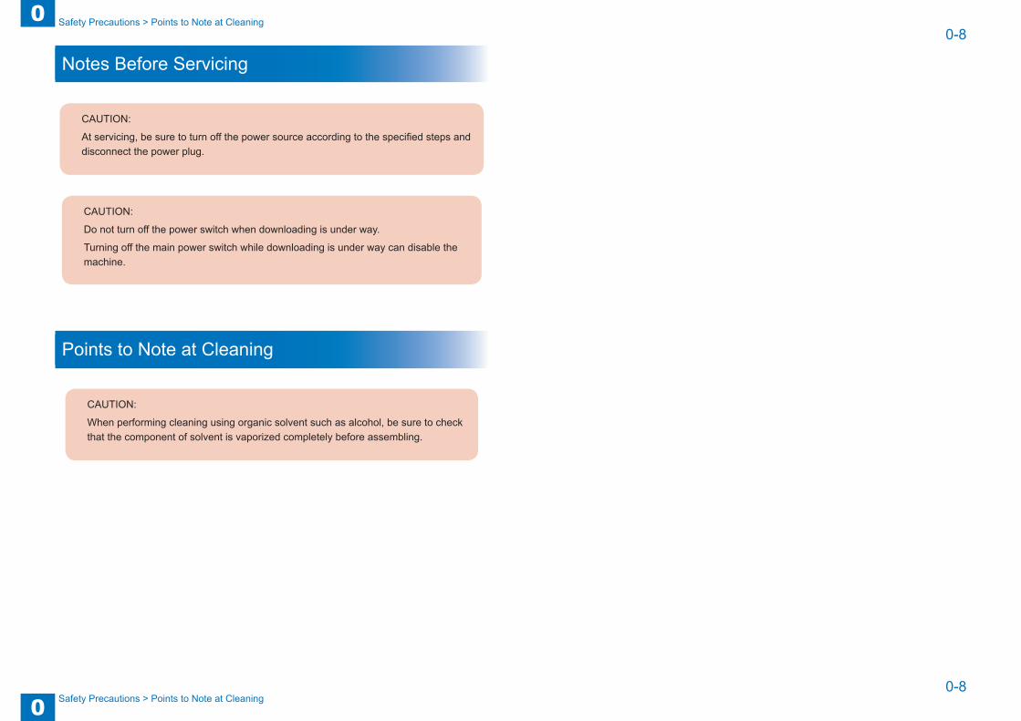
Notes Before Servicing
CAUTION:
At servicing, be sure to turn off the power source according to the specified steps and disconnect the power plug.
CAUTION:
Do not turn off the power switch when downloading is under way.
Turning off the main power switch while downloading is under way can disable the machine.
Points to Note at Cleaning
CAUTION:
When performing cleaning using organic solvent such as alcohol, be sure to check that the component of solvent is vaporized completely before assembling.

1
1 Product Outline
Product Outline ■Features ■Specifications ■Names of Parts

1
11-2
1-2
Product Outline > Specifications
Product Outline > Specifications
Features• Installation improvement
Operation free caster
Specifications ■ Specifications
Item SpecificationsPickup RetardPaper accomodation Front loadingCopy paper Plain paper, recycled paper, thick paper, bond paperPaper weight For iR ADVANCE 4000 Series: 60g/m2 to 128g/m2
For iR ADVANCE C5000 Series: 52g/m2 to 163g/m2Reproduction type A4, LTRPaper stack 2700 sheets(80 g/m2)
3000 sheets(60 g/m2)Dimensions (W) 372mm X (D) 603mm X (H) 473mmWeight 37kgPower supply DC from the host machine
NOTE:The above specifications are subject to change for product improvement.
T-1-1

1
11-3
1-3
Product Outline > Names of Parts
Product Outline > Names of Parts
Names of Parts ■ External View
Deck release grip
Front cover(upper)
Compartment open/close switch
Front cover Right cover
Rear cover
Upper cover
F-1-1
■ Parts Components
M2D
M1D[1]
[2]
[3]
[4]
[5]
[6]
[7][8]
[9]
[11]
[12]
[13]
[14]
[15]
[10]
[1] Deck lifter upper limit sensor (PS3D) [9] Deck lifter motor (M2D)[2] Deck lifter position sensor (PS4D) [10] Pickup roller[3] Deck paper supply position sensor (PS8D) [11] Feed roller[4] Deck paper level sensor (PS7D) [12] Separation roller[5] Deck open detecting switch (SW1D) [13] Deck lifter cable[6] Deck lifter lower limit detecting switch (SW2D)
[14] Lifter
[7] Deck open switch (SW100D) [15] Paper[8] Deck main motor (M1D)
F-1-2

2
2 Technology
Technology ■Basic Configuration ■Controls ■Paper Detection ■Deck Lifter ■Opening /Closing the Compartment ■Detecting Jams ■Power Supply ■Work of Service

2
22-2
2-2
Technology > Basic Configuration > Pickup Operation
Technology > Basic Configuration > Pickup Operation
Basic Configuration
OutlineNumber of sheets 2700 (A4/LTR; paper of 80 g/m2)Operation In response to control signals from the host machine’s DC
controllerDrive Deck lifter motor (M2D) for movement of the deck
Deck main motor (M1D) for pickup/feeding of paper
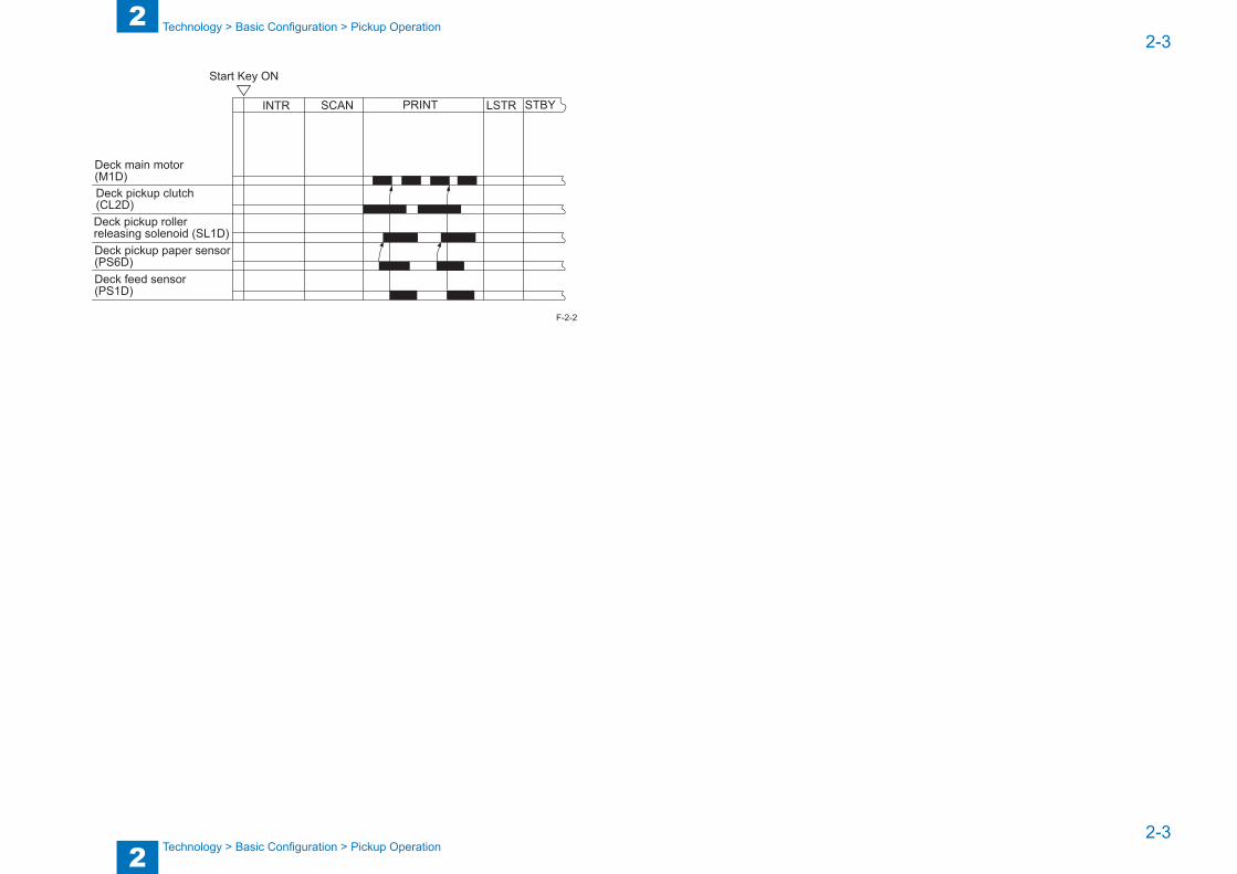
Pickup OperationWhen the Start key is pressed, the deck pickup clutch (CL2D) goes ON. Then, the deck main motor (M1D) goes ON, and the rotation of the pickup roller moves the paper into the machine.The pickup/feeding roller and the separation roller make sure that no more than a single sheet of paper is picked up.After the deck pickup sensor (PS6D) has detected the presence of paper, the pickup roller leaves the surface of paper when the deck pickup roller releasing solenoid (SL1D) goes ON.When paper is fed, the deck feed roller rotates to move the paper to the registration roller of the host machine, where the paper is looped so that it does not skew.The registration roller is controlled so that the image on the photosensitive drum and the leading edge of the paper will match.
T-2-1
<If pickup is not detected within a specific period of time>If, for some reason, the deck pickup sensor (PS6D) does not detect paper in the presence of the deck pickup detection signal, the machine will issue an alarm code.
PS1D
PS6DCL2D
SL1D
M1D
DC controller PCB(host machine)
Deck driver PCB
Dec
k fe
ed d
etec
tion
sign
al(P
_OU
T_S
EN
S)
Dec
k pi
ckup
clu
tch
driv
e si
gnal
(FE
ED
_CL_
ON
*)
Dec
k pi
ckup
rolle
r rel
easi
ng s
olen
oid
driv
e si
gnal
(PIC
KU
P_S
L_O
N*)
Dec
k m
ain
mot
or d
rive
sign
al
Dec
k pi
ckup
det
ectio
n si
gnal
(FE
ED
_SE
NS
)
F-2-1
2
22-3
2-3
Technology > Basic Configuration > Pickup Operation
Technology > Basic Configuration > Pickup Operation
INTR LSTR STBY
Deck main motor(M1D)Deck pickup clutch(CL2D)Deck pickup roller releasing solenoid (SL1D)Deck pickup paper sensor(PS6D)Deck feed sensor(PS1D)
SCAN PRINT
Start Key ON
F-2-2
2
22-4
2-4
Technology > Controls
Technology > Controls
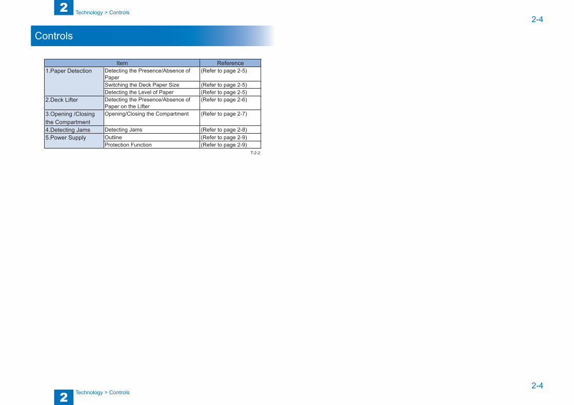
Controls
Item Reference1.Paper Detection Detecting the Presence/Absence of
Paper(Refer to page 2-5)
Switching the Deck Paper Size (Refer to page 2-5)Detecting the Level of Paper (Refer to page 2-5)
2.Deck Lifter Detecting the Presence/Absence of Paper on the Lifter
(Refer to page 2-6)
3.Opening /Closing the Compartment
Opening/Closing the Compartment (Refer to page 2-7)
4.Detecting Jams Detecting Jams (Refer to page 2-8)5.Power Supply Outline (Refer to page 2-9)
Protection Function (Refer to page 2-9)T-2-2

2
22-5
2-5
Technology > Paper Detection > Detecting the Level of Paper
Technology > Paper Detection > Detecting the Level of Paper
Paper Detection
Detecting the Presence/Absence of PaperThe deck paper absent sensor [1] (PS2D) is used to detect the presence/absence of paper.The paper [3] deposited on the lifter [2] runs out.The paper detecting lever [4] of the pickup roller assembly moves past the deck paper absent sensor.The machine indicates a message to indicate the absence of paper (on the host machine’s control panel).
[2]
[1]
[3]
[4]
[2]
[1][4]
F-2-3
Switching the Deck Paper SizeEnter the appropriate paper size in service mode (Lv.1) OPTION>ACC>DK-P.Move the guide plate inside the deck to suit the paper size, and enter the size in service mode (at time of installation or at the request of the user).
Detecting the Level of PaperThe following sensors are used to detect the level of paper:- Deck paper supply position sensor (PS8D)- Deck paper level sensor (PS7D)- Deck paper absent sensor (PS2D)The mechanism of detection can indicate an approximate level of paper inside the compartment on the host machine’s control panel.
Paper level PS2D PS8D PS7D Indication on control panel100% to about 50%
1 1 1
About 50% to about 10%
1 1 0
About 10% or less 1 0 0
No paper 0 0 0T-2-3

2
22-6
2-6
Technology > Deck Lifter > Detecting the Presence/Absence of Paper on the Lifter
Technology > Deck Lifter > Detecting the Presence/Absence of Paper on the Lifter
Deck Lifter
Detecting the Presence/Absence of Paper on the LifterThe deck’s lifter detects the presence/absence of paper as follows:
Operation: Moved up or down by switching the direction of rotation of the deck lifter motor (M2D).
Drive: Obtained from the deck lifter motor (M2D) through cable and reel.
1. Moving Up the LifterThe compartment is pushed inside the deck.The deck open detecting switch (SW1D) is pressed.The deck open sensor (PS9D) detects the light-blocking plate.- Stopping the LifterThe deck lifter position sensor (PS4D) detects the top surface of the stack of paper to stop the lifter.<Preventing damage to the deck caused by excess ascent>An upper limit is set, and it is detected using the deck lifter upper limit sensor (PS3D) in consideration of the following:The sensor lever blocks the deck lifter position sensor for some reason (i.e., the lifter fails to stop its ascent).
2. Moving Down the LifterThe deck open switch (SW100D) is pressed.- Stopping the LifterThe lifter stops where the lifter moves past the sensor lever of the deck paper supply position sensor (PS8D); i.e., at the falling edge of sensor output.<Addition of paper in this condition>The added paper pushes the lever of the deck paper supply position sensor (PS8D).The lifter moves farther down until the stack of paper moves past the sensor lever.
3. Adding PaperEach time paper is added, the lifter repeats moving down until the deck lifter lower limit detecting switch (SW2D) is pressed (i.e., maximum paper supply
level).
M2D
M1D[1]
[2]
[3]
[4]
[5]
[6]
[7][8]
[9]
[11]
[12]
[13]
[14]
[15]
[10]
[1] Deck lifter upper limit sensor (PS3D) [9] Deck lifter motor (M2D)[2] Deck lifter position sensor (PS4D) [10] Pickup roller[3] Deck paper supply position sensor (PS8D) [11] Feed roller[4] Deck paper level sensor (PS7D) [12] Separation roller[5] Deck open detecting switch (SW1D) [13] Deck lifter cable[6] Deck lifter lower limit detecting switch (SW2D)
[14] Lifter
[7] Deck open switch (SW100D) [15] Paper[8] Deck main motor (M1D)

2
22-7
2-7
Technology > Opening /Closing the Compartment > Opening/Closing the Compartment
Technology > Opening /Closing the Compartment > Opening/Closing the Compartment
Opening /Closing the Compartment
Opening/Closing the Compartment<Opening the compartment>The deck open switch (SW100D) is pressed.The deck open solenoid (SL2D) goes on.The compartment is unlocked, and the force of the spring pushes it several centimeters toward the front.The deck lifter motor (M2D) starts to rotate.The lifter inside the compartment moves down.<Closing the compartment>The compartment is pushed inside the deck.The deck open sensor (PS9D) detects the light-blocking plate inside the compartment.The lifter moves up to the pickup motor.<Deck open indicator (LED100D) goes on or flashes>The deck open indicator is used to indicate that the deck lifter motor is rotating to open/close the deck.
Deck lifter lower limit signal (DLLD)
J4- 7
Deck lifter motor drive signalJ4-9,10
M2D
DC
con
trolle
r PC
B
Dec
k dr
iver
PC
B
Deck lifter
Deck open detection signal(DOPD*)
Deck open solenoid drive signal
Deck open signal(DECK_OPEN_SW)
Open Direction
Deck open indictor LED ON signal(LEDSW_LEDON)
SW2D
SL2D
SW1D
Open switch PCB
SW100D
LED100D
J20-1
J20-4
Deck lifter upper limit detection signal(LIFT_M_UPLMT)
PS3D J5A- 9
Deck open detection signal (DECK_OPEN_SENS)
PS9D
(compartment)
J5A- 4
J5A- 1
J6- 7
J7- 3
J6-2
(host machine)
(DECK_LOCKOFF_SL_ON*)
9 : LIFT_M_UP10 : LIFT_M_DOWN( )
F-2-4
* *
Deck open indicator(LED100D)
Deck lifter motor(M2D)
Deck paper supply position sensor (PS8D)
Deck open detecting switch (SW1D)
Deck open solenoid (SL2D)
Deck lifter position sensor (PS4D)
Deck lifter lower limit detecting switch (SW2D)
Deck open sensor(PS9D)
ON FlashingFlashing OFF
Deck open switch ON Compartment set
Compartment open
Deck lifter down Deck lifter up
*:varies depending on the level of paper.
F-2-5
2
22-8
2-8
Technology > Detecting Jams > Overview
Technology > Detecting Jams > Overview
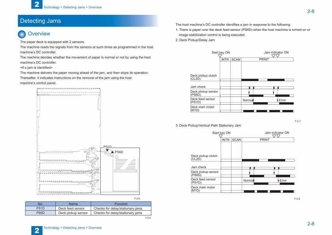
Detecting Jams
OverviewThe paper deck is equipped with 2 sensors.The machine reads the signals from the sensors at such times as programmed in the host machine’s DC controller.The machine decides whether the movement of paper is normal or not by using the host machine’s DC controller.<if a jam is identified>The machine delivers the paper moving ahead of the jam, and then stops its operation. Thereafter, it indicates instructions on the removal of the jam using the hostmachine’s control panel.
PS1D
PS6D
No. Name FunctionPS1D Deck feed sensor Checks for delay/stationary jamsPS6D Deck pickup sensor Checks for delay/stationary jams
F-2-6
T-2-4
The host machine’s DC controller identifies a jam in response to the following:1. There is paper over the deck feed sensor (PS6D) when the host machine is turned on or
image stabilization control is being executed.2. Deck Pickup/Delay Jam
Start key ON Jam indicator ON
INTR SCAN PRINT
Deck pickup clutch (CL2D)
Jam checkDeck pickup sensor (PS6D)Deck feed sensor (PS1D)Deck main motor (M1D)
Normal Error
3. Deck Pickup/Vertical Path Stationery Jam
Start key ON Jam indicator ON
INTR SCAN PRINT
Deck pickup clutch (CL2D)
Jam checkDeck pickup sensor (PS6D)Deck feed sensor (PS1D)Deck main motor (M1D)
Normal Error
F-2-7
F-2-8

2
22-9
2-9
Technology > Power Supply > Protection Function
Technology > Power Supply > Protection Function
Power Supply
Outline ■ Diagram of the Power Supply System.
The following is a diagram of the machine’s power supply system. The side deck is supplied with power by its host machine (24V). The 24V power is convertedby the side deck driver PCB into for output to sensor and the side deck driver PCB.The 5 V power is generated by side deck driver PCB based on 24V power and supplied for driving sensors and the side deck driver PCB.
J0224V
5V
24V- motors- solenoids- clutch- switches
- sensors
Hostmachine
Side deck driver PCB
2FU01
DC5V Power
F-2-9
Protection FunctionThe 24 V power supply is equipped with a fuse (FU01) designed to blow when an overcurrent flows.

2
22-10
2-10
Technology > Work of Service > Upgrading
Technology > Work of Service > Upgrading
Work of Service
When replacing the partsNo. Name Description
1 Deck Pickup Roller Releasing Solenoid (SL1)
Mounting position adjustment
2 Lifter Cable Stringing the Lifter Cable
3 Deck Pickup Roller Direction attention for installation4 Deck Feed Roller Direction attention for installation5 Front Cover Cover gap adjustment for installation
Periodic ServicingPR:Replacement (Periodically replaced parts) CR:Replacement (consumable parts) CL:Cleaning LU:Lubrication AD:Adjustment CH:Maintenance
No. Name Part No. Qty Life1 Pickup roller (front) FF5-7829 1 CR/500,000 sheets2 Pickup roller (rear) FF5-7830 1 CR/500,000 sheets3 Feed roller FF5-7541 1 CR/500,000 sheets4 Separation roller FB2-7777 1 CR/500,000 sheets
UpgradingNone
T-2-5
T-2-6

3
3 Periodic Servicing
Periodic Servicing ■List of Work for Scheduled Servicing

3
33-2
3-2
Periodic Servicing > List of Work for Scheduled Servicing
Periodic Servicing > List of Work for Scheduled Servicing
List of Work for Scheduled ServicingPR:Replacement (Periodically replaced parts) CR:Replacement (consumable parts) CL:Cleaning LU:Lubrication AD:Adjustment CH:MaintenanceAs of Nov 2011
No. Name Part No. Qty Life COUNTER Adjusted/Not adjusted
Remark Reference
1 Pickup roller (front) FF5-7829 1 CR/500,000 sheets DRBL-2>PD-PU-RL No actual number250,000 sheets in the HHenvironment (30 degrees, 80% RH)
(Refer to page 4-9)
2 Pickup roller (rear) FF5-7830 1 CR/500,000 sheets DRBL-2>PD-PU-RL No actual number250,000 sheets in the HHenvironment (30 degrees, 80% RH)
3 Feed roller FF5-7541 1 CR/500,000 sheets DRBL-2>PD-FD-RL No (Refer to page 4-10)
4 Separation roller FB2-7777 1 CR/500,000 sheets DRBL-2>PD-SP-RL No (Refer to page 4-10)
T-3-1

4
4 Parts Replacement and Cleaning Procedure
Parts Replacement and Cleaning Procedure
■List of Parts ■External Covers ■Main Units ■Parts Replacement and Cleaning Procedure. ■Electric Part ■Other Parts

4
44-2
4-2
Parts Replacement and Cleaning Procedure > List of Parts > Main Units
Parts Replacement and Cleaning Procedure > List of Parts > Main Units
List of Parts
External Covers
[6]
[7][5]
[4]
[3]
[1]
[2]
No. Name Refer to[1] Front cover (upper) (Refer to page 4-6)[2] Front cover (Refer to page 4-5)[3] Right cover (Refer to page 4-6)[4] Upper cover (Refer to page 4-6)[5] Rear cover (Refer to page 4-5)[6] Left rear cover (Refer to page 4-5)[7] Left upper cover (Refer to page 4-5)
F-4-1
T-4-1
Main Units
[1]
No. Name Part No Refer to[1] Removing the Deck Pickup Unit FM4-5896 (Refer to page 4-8)
F-4-2
T-4-2

4
44-3
4-3
Parts Replacement and Cleaning Procedure > List of Parts > List of Consumable Parts
Parts Replacement and Cleaning Procedure > List of Parts > List of Consumable Parts
List of Consumable Parts
[1]
[2]
[3]
No. Name Part No Refer to1 Pickup Roller(Front)
Pickup Roller(Rear)FF5-7829FF5-7830
(Refer to page 4-9)
2 Feed Roller FF5-7541 (Refer to page 4-10)3 Separation Roller FB2-7777 (Refer to page 4-10)
T-4-3

4
44-4
4-4
Parts Replacement and Cleaning Procedure > List of Parts > Electric Part
Parts Replacement and Cleaning Procedure > List of Parts > Electric Part
Electric Part
SW2D
SW1D
PS6D
PS5D
PS1D
PS4D
PS2DPS3D
PS7D
SW100D
PS9D
PS8D
M1D
[PCB]
SL2D
M2D
SL1D
LED100D
CL2D
F-4-3
No. Name Refer toCL2D Deck pickup clutch (Refer to
page 4-11)SL1D Deck pickup roller release solenoid -SL2D Deck open solenoid -SW1D Deck open sensing switch -SW2D Deck lifter lower limit sensing switch -
SW100D Deck open switch (Refer to page 4-13)LED100D Deck open indication
M1D Deck main motor (Refer to page 4-11)
M2D Deck lifter motor (Refer to page 4-12)
PS1D Deck feeder sensor -PS2D Deck paper-out sensor -PS3D Deck lifter upper limit sensor -PS4D Deck lifter position sensor -PS5D Deck set sensor -PS6D Deck pickup sensor -PS7D Deck paper level sensor -PS8D Deck paper replenishing position sensor -PS9D Deck open sensor -[PCB] Deck contoroller PCB (Refer to
page 4-13)T-4-4

4
44-5
4-5
Parts Replacement and Cleaning Procedure > External Covers
Parts Replacement and Cleaning Procedure > External Covers
External Covers ■ Removing the Left Rear Cover
1) Free the deck from its host machine.2) Remove the 2 screws [1] and 2 self-tapping screws [3]; then, detach the left rear cover [3].
■ Removing the Front Cover1) Remove the 4 screws [1], and detach the front cover [2] to the front. Do not
[1]
[2]
F-4-4
F-4-5
■ Removing the Left Upper Cover1) Remove the 2 screws [1], and detach the left upper cover.
■ Removing the Rear Cover1) Remove the 2 binding screws [1] and the 4 RS tightening screws [3]; then,detach the rear
cover [2].
F-4-6
F-4-7

4
44-6
4-6
Parts Replacement and Cleaning Procedure > External Covers
Parts Replacement and Cleaning Procedure > External Covers
■ Removing the Front Cover (upper)1) Remove the 3 screws [1], and disconnect the connector; then, detach the front cover (upper)
[3].
CAUTION:
When mounting the front cover (upper), be sure that the harness to the open switch PCB is not trapped and all connectors are properly connected.
■ Removing the Upper Cover1) Remove the 2 screws [1], and detach the upper cover [2].
F-4-8
F-4-9
■ Removing the Right Cover1) Remove the 3 screws [1], and shift down the right cover [2], then, detach it toward the
front.
F-4-10

4
44-7
4-7
Parts Replacement and Cleaning Procedure > External Covers
Parts Replacement and Cleaning Procedure > External Covers
CAUTION:
When mounting the right cover, be sure that the claw [1] on the top of the right cover is in the hole [2] of the paper deck stay and the right edge [3] is inside the rear cover [4].
F-4-11

4
44-8
4-8
Parts Replacement and Cleaning Procedure > Main Units > Removing the Deck Pickup Unit
Parts Replacement and Cleaning Procedure > Main Units > Removing the Deck Pickup Unit
Main Units
Removing the Deck Pickup Unit1) Remove the left rear cover."Removing the Left Rear Cover"(page 4-5).2) Remove the left upper cover."Removing the Left Upper Cover"(page 4-5).3) Remove the rear cover."Removing the Rear Cover"(page 4-5).4) Remove the front cover (upper)."Removing the Front Cover (upper)"(page 4-6).5) Remove the upper cover."Removing the Upper Cover"(page 4-6).6) Detach the deck release grip [1] in upward direction.7) Disconnect the 2 connectors [2], and remove the 5 screws [3].8) Detach the pickup harness [4].9) Remove the deck pickup unit [5].
F-4-12
CAUTION:
When mourning the deck pickup unit [1], tighten the 3 screws [2] first and then the remaining 2 screws [3].
F-4-13

4
44-9
4-9
Parts Replacement and Cleaning Procedure > Parts Replacement and Cleaning Procedure.
Parts Replacement and Cleaning Procedure > Parts Replacement and Cleaning Procedure.
Parts Replacement and Cleaning Procedure. ■ Removing the Deck Pickup Roller
1) Remove the left rear cover."Removing the Left Rear Cover"(page 4-5).2) Remove the left upper cover."Removing the Upper Cover"(page 4-6).3) Remove the rear cover."Removing the Rear Cover"(page 4-5).4) Remove the front cover (upper)."Removing the Front Cover (upper)"(page 4-6).5) Remove the upper cover."Removing the Upper Cover"(page 4-6).6) Remove the deck pickup unit."Removing the Deck Pickup Unit"(page 4-8).7) Turn over the deck pickup unit; then, remove the resin ring [1] (1 each) and 2 deck pickup
rollers [2].
[1]
[2]
CAUTION:
The pickup roller has its own orientation (direction of rotation), requiring care when mounting it.
F-4-14
■ Points to Note When Mounting the Pickup Roller
● Front of the MachineThe pickup roller has its own orientation [1].When mounting the deck pickup roller [2] found at the front of the machine, be sure that the marking [4] on the collar [3] is toward the front of the machine and the marking [5] on the side of the roller is toward the rear of the machine.
● Rear of the MachineThe pickup roller has its own orientation [6]. When mounting the deck pickup roller [7] at the rear of the machine, be sure that the marking [9] on the collar [8] and the marking [10] on the side of the roller are toward the rear of the machine.
[6]
[7]
[9]
[8][10]
[1]
[2][4]
[5][3]
F-4-15

4
44-10
4-10
Parts Replacement and Cleaning Procedure > Parts Replacement and Cleaning Procedure.
Parts Replacement and Cleaning Procedure > Parts Replacement and Cleaning Procedure.
■ Removing the Deck Feed Roller1) Remove the left rear cover."Removing the Left Rear Cover"(page 4-5).2) Remove the left upper cover."Removing the Left Upper Cover"(page 4-5).3) Remove the rear cover."Removing the Rear Cover"(page 4-5).4) Remove the front cover (upper)."Removing the Front Cover (upper)"(page 4-6).5) Remove the upper cover."Removing the Upper Cover"(page 4-6).6) Remove the deck pickup unit."Removing the Deck Pickup Unit"(page 4-8).7) Remove the resin ring [1], and detach the deck pickup/feed roller [2] and the drive belt [3]
to the front.
[2]
[3]
[1]
■ Points to Note When Mounting the Deck Feed RollerWhen mounting the deck feed roller [1], be sure that the belt pulley [2] is toward the front of the machine. There is no specific orientation to observe when fitting the feed roller rubber to the feed roller shaft.
[1]
[2]
F-4-16
F-4-17
■ Removing the Deck Separation Roller1) Free the deck from its host machine, and remove the 2 screws [1] and the separation roller
support plate [2].
2) Detach the pickup roller [1] from the holder [2].
[1][2]
3) Detach the shaft [1] in the direction of the arrow.
[1]
CAUTION:
The urethane sponge segment of the deck separation roller is pink immediately after foaming; it changes in color from pink to orange and then to yellow as time passes, accelerated if exposed to light.
This is a general characteristic of a urethane sponge, and will not affect its performance.
The part is not identified by its color, and there are not multiple parts classified according to color.
F-4-18
F-4-19
F-4-20

4
44-11
4-11
Parts Replacement and Cleaning Procedure > Electric Part
Parts Replacement and Cleaning Procedure > Electric Part
Electric Part ■ Removing the Deck Pickup Clutch (CL2D)
1) Remove the left rear cover."Removing the Left Rear Cover"(page 4-5).2) Remove the left upper cover."Removing the Upper Cover"(page 4-6).3) Remove the rear cover."Removing the Rear Cover"(page 4-5).4) Remove the front cover (upper)."Removing the Front Cover (upper)"(page 4-6).5) Remove the upper cover."Removing the Upper Cover"(page 4-6).6) Remove the deck pickup unit."Removing the Deck Pickup Unit"(page 4-8).7) Disconnect the connector [1], and remove the E-ring [2]; then, detach the deck pickup
clutch [3].
CAUTION:
When mounting the deck pickup clutch, be sure that the clutch is fitted to the stop [4]. Also, be sure that the harness is fitted to the U-groove [5] of the guide.
[1]
[3]
[2][4] [5]
F-4-21
■ Removing the Deck Main Motor (M1D)1) Remove the left rear cover."Removing the Left Rear Cover"(page 4-5).2) Remove the rear cover."Removing the Rear Cover"(page 4-5).
CAUTION:
Disconnect the connector [1], and remove the 2 screws [2]; then, detach the deck main motor [3].
At this time, take care not to damage the gear found at the tip of the motor spindle
[1]
[3]
[2]
[2]
4
44-12
4-12
Parts Replacement and Cleaning Procedure > Electric Part
Parts Replacement and Cleaning Procedure > Electric Part
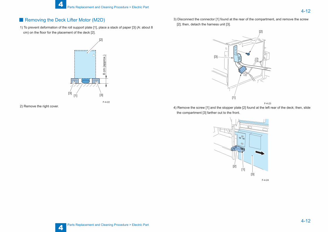
■ Removing the Deck Lifter Motor (M2D)1) To prevent deformation of the roll support plate [1], place a stack of paper [3] (A: about 8
cm) on the floor for the placement of the deck [2].
[2]
[3][3][1]
8 cm
(app
rox.
)2) Remove the right cover.
F-4-22
3) Disconnect the connector [1] found at the rear of the compartment, and remove the screw [2]; then, detach the harness unit [3].
[1]
[3]
[2]
4) Remove the screw [1] and the stopper plate [2] found at the left rear of the deck; then, slide the compartment [3] farther out to the front.
[3]
[2][1]
F-4-23
F-4-24

4
44-13
4-13
Parts Replacement and Cleaning Procedure > Electric Part
Parts Replacement and Cleaning Procedure > Electric Part
5) Remove the 3 screws [2] each from the left/right of the compartment rail [1]; then, lift the compartment [3] about 1 cm, and detach it to the front.
6) Place the compartment on the stack of paper you have previously pre-pared. Be sure to use the stack of paper to prevent deformation of the roll support plate.
7) Disconnect the connector [1], and remove the 5 screws [2]; then, detach the deck lifter motor unit [3].
[1]
[2]
[2][3]
F-4-25
F-4-26
■ Removing the Deck Driver PCB1) Remove the left rear cover."Removing the Left Rear Cover"(page 4-5).2) Remove the rear cover."Removing the Rear Cover"(page 4-5).3) Disconnect the 8 connectors [1], and remove the 4 screws [2]; then, detach the deck driver
PCB [3].
■ Removing the Open Switch PCB1) Open the compartment."How to open deck"(page 4-14).2) Remove the front cover (upper)."Removing the Front Cover (upper)"(page 4-6).3) Remove the 2 screws [2] from inside the front cover (upper) [1], and detach the open
switch PCB [3].
[3]
[1]
[2]
F-4-27
F-4-28

4
44-14
4-14
Parts Replacement and Cleaning Procedure > Other Parts > Removing from the Host Machine > How to open deck
Parts Replacement and Cleaning Procedure > Other Parts > Removing from the Host Machine > How to open deck
Other Parts
Removing from the Host Machine ■ Cassette Heater Unit
When the cassette heater unit is installed in the paper deck, remove it necessarily prior to disassembling.
■ Previous preparations1) To prevent deformation of the roll support plate [1], place a stack of paper [3] (A: about 8
cm) on the floor for the placement of the deck [2].
[2]
[3][3][1]
A
F-4-29
■ Detaching the Deck From Its Host Machine1) Remove the the connect acble.2) Push the deck release grip [1] to free the deck form its host machine.3) Remove the 3 screws from the left side, and detach the deck.
[1]
[2]
■ How to open deck1) Push the deck release grip [1] to free the deck form its host machine; then,push down the
latch plate [2] found at the left rear to open the compartment.
F-4-30
F-4-31

4
44-15
4-15
Parts Replacement and Cleaning Procedure > Other Parts > Lifter part > Positioning the Deck Lifter
Parts Replacement and Cleaning Procedure > Other Parts > Lifter part > Positioning the Deck Lifter
Lifter part ■ Positioning the Deck Lifter
1) Push the deck release grip [1] to free the deck form its host machine; then,push down the latch plate [2] found at the left rear to open the compartment.
2) If there is any paper, remove all of it.3) Connect the power plug, and turn on the host machine.4) Push the sensor flag [2] of the paper supply position sensor found inside the compartment
[1] so that the deck lifter moves down. (The deck lifter will stop as soon as you release the flag.)
[2] [1]
NOTE:If the deck lifter [1] is in up position, move it so that distance A from the base plate of the compartment of the deck is about 7cm.
[1]
A
F-4-32
F-4-33
6) Insert a hex wrench [3] into the hole of the lifter drive shaft [2] so that itserves to keep the spindle from turning.
[1]
[2]
7) Disconnect the power plug.F-4-34
4
44-16
4-16
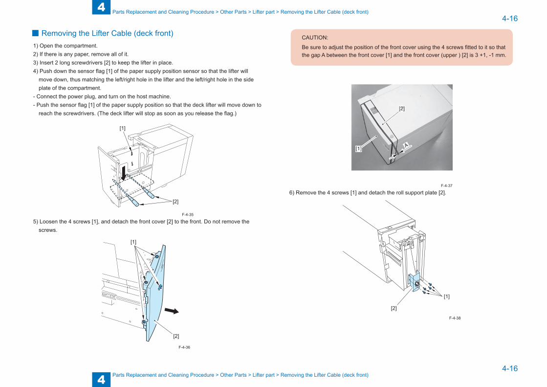
Parts Replacement and Cleaning Procedure > Other Parts > Lifter part > Removing the Lifter Cable (deck front)
Parts Replacement and Cleaning Procedure > Other Parts > Lifter part > Removing the Lifter Cable (deck front)
■ Removing the Lifter Cable (deck front)1) Open the compartment.2) If there is any paper, remove all of it.3) Insert 2 long screwdrivers [2] to keep the lifter in place.4) Push down the sensor flag [1] of the paper supply position sensor so that the lifter will
move down, thus matching the left/right hole in the lifter and the left/right hole in the side plate of the compartment.
- Connect the power plug, and turn on the host machine.- Push the sensor flag [1] of the paper supply position so that the deck lifter will move down to
reach the screwdrivers. (The deck lifter will stop as soon as you release the flag.)
[1]
[2]
5) Loosen the 4 screws [1], and detach the front cover [2] to the front. Do not remove the screws.
[1]
[2]
F-4-35
F-4-36
CAUTION:
Be sure to adjust the position of the front cover using the 4 screws fitted to it so that the gap A between the front cover [1] and the front cover (upper ) [2] is 3 +1, -1 mm.
6) Remove the 4 screws [1] and detach the roll support plate [2].
[2]
[1]
F-4-37
F-4-38

4
44-17
4-17
Parts Replacement and Cleaning Procedure > Other Parts > Lifter part > Removing the Lifter Cable (deck rear)
Parts Replacement and Cleaning Procedure > Other Parts > Lifter part > Removing the Lifter Cable (deck rear)
7) Remove the E-ring [2], and detach the pulley cover [3].8) Remove the 2 screws [4] and the cable fixing plate [5] found on the left side; then, detach
the lifter cable [6].9) Remove the 2 screws [7] and the cable fixing plate [8] found on the right side; then, detach
the lifter cable [9].10) Detach the inside lifter cable [9] from the inside pulley [1] by removing the 2 set screws [12]
and then the outside pulley [11].
[10] [5] [8]
[3] [4] [9][11]
[7] [6][2]
[1]
CAUTION:
When mounting the pulley cover, be sure to mach the claw [A] against the hole in the front side plate of the compartment..
[A]
F-4-39
F-4-40
■ Removing the Lifter Cable (deck rear)1) Open the compartment.2) If there is any paper, remove all of it.3) Remove the screw [1], and detach the upper sensor cover [2] and the lower sensor cover [3].4) Disconnect the 4 connectors [4].
[1]
[4][2]
[3]
[4]
[4]
CAUTION:
There are 2 claws on the top of the sensor cover; be sure to take care not to break them when removing the cover.
F-4-41

4
44-18
4-18
Parts Replacement and Cleaning Procedure > Other Parts > Lifter part > Removing the Lifter Cable (deck rear)
Parts Replacement and Cleaning Procedure > Other Parts > Lifter part > Removing the Lifter Cable (deck rear)
5) Remove the 5 screws [2], and detach the plate [1].
[2]
[1]
[2]
[2]
6) Insert a hex wrench [2] or the like into the hole of the lifter drive shaft [1] to keep it from turning.
CAUTION:
If you fail to perform this step, the lifter cable will become slack as soon as you remove the lifter motor unit.
[1]
[2]
7) Remove the lifter motor unit.
F-4-42
F-4-43
8) Remove the bearing [1], gear [2], parallel pin [3], E-ring [4], and detach the pulley cover [5].9) Remove the 2 screws [6], and detach the right cable fixing plate [7]; then, detach the
outside lifter cable [8].10) Remove the 2 screws [9], and detach the left cable fixing plate [10]; then, detach the
inside lifter cable [11].11) Remove the 2 set screws and detach the outside pulley [13] to detach the inside lifter
cable [11] from the inside pulley [12].
[1]
[2]
[3][4]
[5]
[8][11]
[6][7]
[12][13]
[9] [10]
F-4-44

4
44-19
4-19
Parts Replacement and Cleaning Procedure > Other Parts > Lifter part > Routing the Lifter Cable
Parts Replacement and Cleaning Procedure > Other Parts > Lifter part > Routing the Lifter Cable
■ Routing the Lifter Cable1) Check to be sure that the lifter driver shaft [1] and the lifter [2] are fixed in place by the 2
hex screwdrivers [4] and a hex wrench [3] or the like.2) Secure the 4 cable fixing plates [5] in place to the lifter using 2 screws each.3) Hook the lifter cable [6] on the 4 pulleys [7].4) Hook the ball of the lifter cable on the 2 pulleys found at the front/rear of the lifter drive
shaft; then, wind the cable about 1.5 times along the groove of the pulley. At this time, see to it that the lifter cable is taut just enough to lift the long screwdrivers used
to keep the lifter in place.5) Secure the 2 pulleys [5] in place to the lifer drive shaft using a set screw [9] (1 each).6) After mounting all pulleys you have removed to the lifter drive shaft,measure the height
A from the base plate of the compartment to the top surface of the lifter at several points, thereby making sure that the lifter is level.
[4]
[8]
[9]
[5]
[7]
[7]
[1]
[2][5]
[9][8]
[3][5]
[6]
[5]
[A]
[A]
[A]
[A]
F-4-45

5
5 Adjustments
Adjustments ■Basic Adjustment ■Measures at Time of Parts Replacement

5
55-2
5-2
Adjustments > Adjustment > Basic Adjustment > Adjusting the Pressure of the Deck Separation Roller
Adjustments > Adjustment > Basic Adjustment > Adjusting the Pressure of the Deck Separation Roller
Adjustment
Basic Adjustment ■ Checking the Image Rear/Front Position for Pickup from the
Side Paper DeckMake a 100% copy, and check to make sure that the margin on the front of the image is 2.0 -/+1.0 mm; if not, adjust the registration.
02
4
6
810
(-) (+)
2.0±1.5mm
■ Adjusting the Rear/Front Registration for the Side Paper Deck1) Push the deck releasing grip [1] to detach the deck from the host machine;1 then, push
down the latch plate [2] found at the left rear with a finger to open the compartment.
F-5-1
F-5-2
3) Close the compartment, and check to make sure that the gap of the front cover is 3 -/+1 mm.
4) If not 3 -/+1 mm, adjust the front cover.
3±1mm
[2]
[1]
■ Adjusting the Pressure of the Deck Separation RollerIf pickup faults or double feeding occurs when the deck is used as the source of paper, relocate the pressure spring [2] of the deck separation roller [1]:- If pickup faults occur, move the spring in the direction of arrow A.- If double-feeding occurs, move the spring in the direction of arrow B.
A
B
[1]
[2]
F-5-3
F-5-4

5
55-3
5-3
Adjustments > Adjustment > Basic Adjustment > Adjusting the Position of the Spacer
Adjustments > Adjustment > Basic Adjustment > Adjusting the Position of the Spacer
■ Adjusting the Position of the SpacerIf the compartment cannot be opened/closed smoothly and, thus, requires adjustment of the spacer mounted to the front of the deck, go through the following:1) Push the deck releasing grip [1] to detach the deck from the host machine;then, push down
the latch plate [2] found at the left rear with a finger to open the compartment.2) Loosen the 4 screws [1], and detach the front cover [2] toward the front. Do not remove these screws.
[1]
[2]
F-5-5
CAUTION:
• When attaching the front cover, be sure that the coupling [1] used to indicate the paper level is correctly matched.
[1]• Adjust the position of the front cover by using 4 screws on it so that gap A between
the front cover [1] and the front cover top [2] is 3 -/+1 mm.• If you moved the paper level indicator belt or the deck lifter, you must adjust the
paper level indicator.
[1]
[2]
A
F-5-6
F-5-7

5
55-4
5-4
Adjustments > Adjustment > Basic Adjustment > Adjusting the Position of the Spacer
Adjustments > Adjustment > Basic Adjustment > Adjusting the Position of the Spacer
3) Move the drive belt [2] of the paper level indicator found in the front cover [1] in the direction of the arrow [4] lightly by hand (i.e., so that the area of white increases).
[1]
[2]
[3]
[4]
CAUTION:
Keep in mind that you can damage the drive mechanism of the paper level indicator if you operate the deck without correcting the spatial relationship between the paper level indicator and the deck lifter.
F-5-8
4) With the compartment set in the deck, turn the 4 mounting screws [4] of the spacer support plate [3] so that the distance A between the spacer [1] and the floor [2] is about 5 mm.
[4]
[5]
[2][1]
[3]A
[4]
NOTE:At this time, use the index [5] on the front side plate as a reference.
F-5-9

5
55-5
5-5
Adjustments > Adjustment > Basic Adjustment > Switching the Paper Size of the Deck
Adjustments > Adjustment > Basic Adjustment > Switching the Paper Size of the Deck
■ Adjusting the Height of the Side Spacera. Before Starting the Work1) Slide the machine out of its host machine, and then slide it back in. Check to see if the
impact of the movement has displaced the host machine or if the machine has wobbled. If so, adjust the height of the side spacer; otherwise,this adjustment may be skipped.
b. Making Adjustments1) Connect the machine to its host machine.2) Remove all paper from the deck.3) Remove the machine's right cover.4) Loosen the 2 fixing screws [2] of the side spacer [1].5) Bring the side spacer in contact with the floor, and tighten the fixing screw.
[1]
[2]
NOTE:At this time, refer to the indexes so that the left and right screws are at the index.
6) Disconnect and then connect the machine from and to its host machine. If the movement is not heavy, attach the machine's right cover, put paper back in, and then end the work. If the movement is heavy, go to the next step.
7) Check the index of the side spacer.8) Loosen the side spacer fixing screw.9) By referring to the index, move the side spacer up by 1 mm; then, tighten the fixing screw.10) Attach the right, and put paper in the deck
F-5-10
■ Switching the Paper Size of the DeckAs needed to suit the user's needs, go through the following to change the deck paper size:1) Push the deck releasing grip [1] to detach the deck from the host machine;then, push down
the latch plate [2] found at the left rear with a finger to open the compartment.2) Loosen the 4 screws [1], and detach the front cover [2] toward the front. Do not remove
these screws.
[1]
[2]
F-5-11

5
55-6
5-6
Adjustments > Adjustment > Basic Adjustment > Adjusting the Paper Level Indicator
Adjustments > Adjustment > Basic Adjustment > Adjusting the Paper Level Indicator
CAUTION:
• When attaching the front cover, be sure that the coupling [1] used to indicate the paper level is correctly matched.
[1]• Adjust the position of the front cover by using 4 screws on it so that gap A between
the front cover [1] and the front cover top [2] is 3 -/+1 mm.• If you moved the paper level indicator belt or the deck lifter, you must adjust the
paper level indicator.
[1]
[2]
A
F-5-12
F-5-13
■ Adjusting the Paper Level Indicator1) Move the drive belt [2] of the paper level indicator found in the front cover [1] in the
direction of the arrow [4] lightly by hand (i.e., so that the area of white increases).
[1]
[2]
[3]
[4]
CAUTION:
Keep in mind that you can damage the drive mechanism of the paper level indicator if you operate the deck without correcting the spatial relationship between the paper level indicator and the deck lifter.
F-5-14

5
55-7
5-7
Adjustments > Adjustment > Basic Adjustment > Adjusting the Paper Level Indicator
Adjustments > Adjustment > Basic Adjustment > Adjusting the Paper Level Indicator
2) If the lifter is up, move it to its lower limit.3) Remove the screw [1], and fit the paper trailing edge guide plate [2] to suit the new paper
size. (Do not perform this step if for LTR.)4) Remove the screw [3] (1 each), and fit the left/right guide plate [4] to suit the new paper
size.
[2] [1] [3]
[4]
5) Execute 'machine specifications selection' in source mode to set the new paper size.
NOTE:(Lv.1) COPIER>OPTION>ACC>DK-Pmachine specifications selection
F-5-15

5
55-8
5-8
Adjustments > Adjustment > Measures at Time of Parts Replacement > Stringing the Lifter Cable
Adjustments > Adjustment > Measures at Time of Parts Replacement > Stringing the Lifter Cable
Measures at Time of Parts Replacement ■ Position of the Deck Pickup Roller Releasing Solenoid (SL1)
Before removing the deck pickup roller releasing solenoid [1] from the support plate, takemental note of the position of the 2 fixing screws [2] with reference to the index on thesupport plate. Or, mark the position of the solenoid on the support with a scriber. When mounting the solenoid on its own, secure it in place to its initial position.
[1]
[2]
F-5-16
■ Stringing the Lifter Cable1) Check to make sure that the lifter drive shaft [1] and the lifter [2] are fixed in place using a
hex wrench [3] and 2 long screwdrivers [4], respectively.2) Fix the 4 cable fixing plates [5] in place to the lifter using 2 screws each.3) Hook the lifer cable [6] on the 4 pulleys [7] above.4) Hook the ball of the lifter cable on the 2 front/rear pulleys [8] of the lifter drive shaft; then,
wind it about 1.5 times along the groove of the pulley. At this time, be sure to keep the lifter cable taut so that the long drivers used to keep the
lifter are slightly lifted by the cable.5) Fix the 2 pulleys [5] in place to the lifter drive shaft with a set screw [9] (1 pc. each).6) Fit all removed pulleys to the lifter shaft; then, measure the height A from the base plate of
the compartment to the top face of the lifter, thus making sure that the lifter is level.
[A]
[A]
[A]
[A]
[3]
[4][5]
[5]
[5]
[5]
[6]
[7]
[7]
[8] [9]
[8]
[9]
[1]
F-5-17

5
55-9
5-9
Adjustments > Adjustment > Measures at Time of Parts Replacement > Points to Note When Mounting the Deck Feed Roller
Adjustments > Adjustment > Measures at Time of Parts Replacement > Points to Note When Mounting the Deck Feed Roller
■ Points to Note When Mounting the Deck Pickup RollerFront of the Machine (collar [3]; silver-colored)It has its own direction of rotation [1]; when mounting the deck pickup roller [2] to the front of the machine, be sure that the marking [4] found on the collar [3] is to the front of the machine.Rear of the Machine (collar [7]; gold-cover)It has its own direction of rotation [6]; when mounting the deck pickup roller [6] to the rear of the machine, be sure that the marking [8] found on the collar [7] is to the rear of the machine.
[1]
[2][3]
[4]
[5]
[6][7]
[8]
F-5-18
■ Points to Note When Mounting the Deck Feed RollerWhen mounting the deck feed roller [1], be sure so that the belt pulley [2] is to the front of the machine.
[1]
[2]
F-5-19

5
55-10
5-10
Adjustments > Adjustment > Measures at Time of Parts Replacement > Points to Note When Mounting the Front Cover
Adjustments > Adjustment > Measures at Time of Parts Replacement > Points to Note When Mounting the Front Cover
■ Points to Note When Mounting the Front Cover1) When mounting the front cover to the deck, be sure to match it against the coupling for the
paper level indicator.
[1]
2) Be sure to mount the front cover [1] so that the gap between the front over [1] and the upper front cover [2] is 3 +/-1 mm.
3) If you moved the paper level indicator belt or the deck lifter, you must adjust the paper level indicator.
3±1mm
[2]
[1]
F-5-20
F-5-21
CAUTION:
If you inadvertently moved the paper level indicator belt [2] behind the front cover [1] when removing the front cover, or moved the deck lifter,move the deck lifter to its lower limit, and then move the arrow (shown in the figure to the right) until it stops so that the area [3] of white increase; then,mount the front cover.
(If the deck is operated without matching the paper level indicator and the deck lifter position, the drive mechanisms of the paper level indicator can suffer damage.)
[3][1]
[2]
F-5-22

6
6 Installation
Installation ■How to Utilize This Installation Procedure ■Product Name ■Checks to Make before Installation ■Check items when Turning OFF the Main Power ■Checking the Supplied Parts ■Unpacking Procedure ■Installation procedure ■Changing the Paper Size ■Adjustment

6
66-2
6-2
Installation > Check items when Turning OFF the Main Power
Installation > Check items when Turning OFF the Main Power
How to Utilize This Installation Procedure
When Using the Contained Parts (Bundled Components in the Shipping Carton)
A syambole is described on the illustration in the case of using the parts included in thepackage of this product.
Packaged Item
Symbols in the IllustrationThe frequently-performed operations are described with symbols in this procedure.
Connector
Disconnect
Screw
Tighten Remove Connect Secure Free
Harness
PushInsert Plug in Turn on
Sound CheckCheck Visual Check
Claw
Remove
Checking instruction
F-6-1
F-6-2
Product NameSafety regulations require the product's name to be registered. In some regions where this product is sold, the following name may be registered instead.
F280370
Checks to Make before InstallationThe minimum space required for installation and maintenance is shown below.
100 mm or more
500 mm or more
Check items when Turning OFF the Main Power1. The host machine and the pedestal have properly been installed.2. Check that the main power switch is OFF.
1) Turn OFF the main power switch of the host machine.2) Be sure that the control panel display and the main power lamp are both turned OFF,
and then disconnect the power plug.
F-6-3

6
66-3
6-3
Installation > Checking the Supplied Parts
Installation > Checking the Supplied Parts
Checking the Supplied PartsOpen the container box and check that none of the included parts is missing.
[5][11]
[18]
[1][3]
[4]
[7]
[6]
[2]
[5]
[8]
[9]
[13]
C
C
B
A
[5]
[5]
[17]
[12]
[10]
iR ADVANCE 4000s
iR ADVANCE C5000s
[5]
[5][16]
[14]
[5]
[15]
F-6-4
□ [1] Paper deck 1unit□ [2] Lifter plate sheet 1pc (*1)□ [3] Open label 1pc□ [4] Paper deck right cover 1pc□ [5] Binding screw (M4x8) 12pcs (*2)□ [6] Bottom stay cover 2pcs□ [7] Paper size label 1pc□ [8] Roller support plate 1pc□ [9] Right cover guide 1pc□ [10] Deck mounting stay 1pc□ [11] Latch front cover 1pc□ [12] Latch catch guide 1pc□ [13] Wire saddle 1pc
For iR ADVANCE 4000 series
□ [14] Binding screw (M4x30)(Silver) 5pcs□ [15] Latch catch A 1pc□ [16] Latch catch B 1pc
For iR ADVANCE C5000 series
□ [17] Binding screw (M4x40)(Black) 5pcs□ [18] Latch catch C 2pcs
*1: A4 model only (Not included for LTR model)*2: Use 12 pieces of the screws when this unit is equipped to iR ADVANCE C5000 series. Use 11 pieces of the screws when this unit is equipped to iR ADVANCE 4000 series.

6
66-4
6-4
Installation > Unpacking Procedure
Installation > Unpacking Procedure
Unpacking Procedure
CAUTION:
The paper deck is secured with packaging tapes and cushioning materials to protect it against vibration and shock during transportation. Remove all packaging tapes and cushioning materials before installing the equipment. Save the removed cushioning materials in case you need to use them again to transport the equipment for relocation or repair.
1) Open the plastic packing bag of the paper deck and then take out the paper deck from the palette.
Caution:
When holding the paper deck at the installation, be ready with the two persons and surely hold the right and left stays. Fail to do so may result in the deformation of the paper deck. (Weight: approximately 30 kg)
F-6-5
2) Remove the roller pressure release part and the package tape from the paper deck.
F-6-6

6
66-5
6-5
Installation > Installation procedure > Installation procedure(iR ADVANCE 4000 series) > Preparing at the Host Machine
Installation > Installation procedure > Installation procedure(iR ADVANCE 4000 series) > Preparing at the Host Machine
Installation procedure
Installation procedure(iR ADVANCE 4000 series)
NOTE: Follow the installation procedure depending on the connected host machine as the procedures are different for each.-When the paper deck is connected to iR ADVANCE C5000 series, see p. 6-14.
■ Preparing at the Host Machine
1) Draw out the upper cassette. Then cut the blindfold covers on the front side, right front side and right rear side of the host machine using the nipper.
NOTE:Be sure to check that there is no burr after cutting with nippers.
F-6-7
6
66-6
6-6
Installation > Installation procedure > Installation procedure(iR ADVANCE 4000 series) > Preparing at the Host Machine
Installation > Installation procedure > Installation procedure(iR ADVANCE 4000 series) > Preparing at the Host Machine
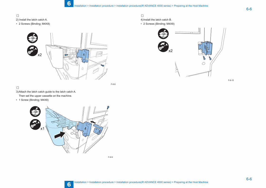
2) Install the latch catch A.• 2 Screws (Binding; M4X8)
x2
3) Attach the latch catch guide to the latch catch A. Then set the upper cassette on the machine.• 1 Screw (Binding; M4X8)
x1
F-6-8
F-6-9
4) Install the latch catch B.• 2 Screws (Binding; M4X8)
Bx2
F-6-10
6
66-7
6-7
Installation > Installation procedure > Installation procedure(iR ADVANCE 4000 series) > Preparing at the Host Machine
Installation > Installation procedure > Installation procedure(iR ADVANCE 4000 series) > Preparing at the Host Machine
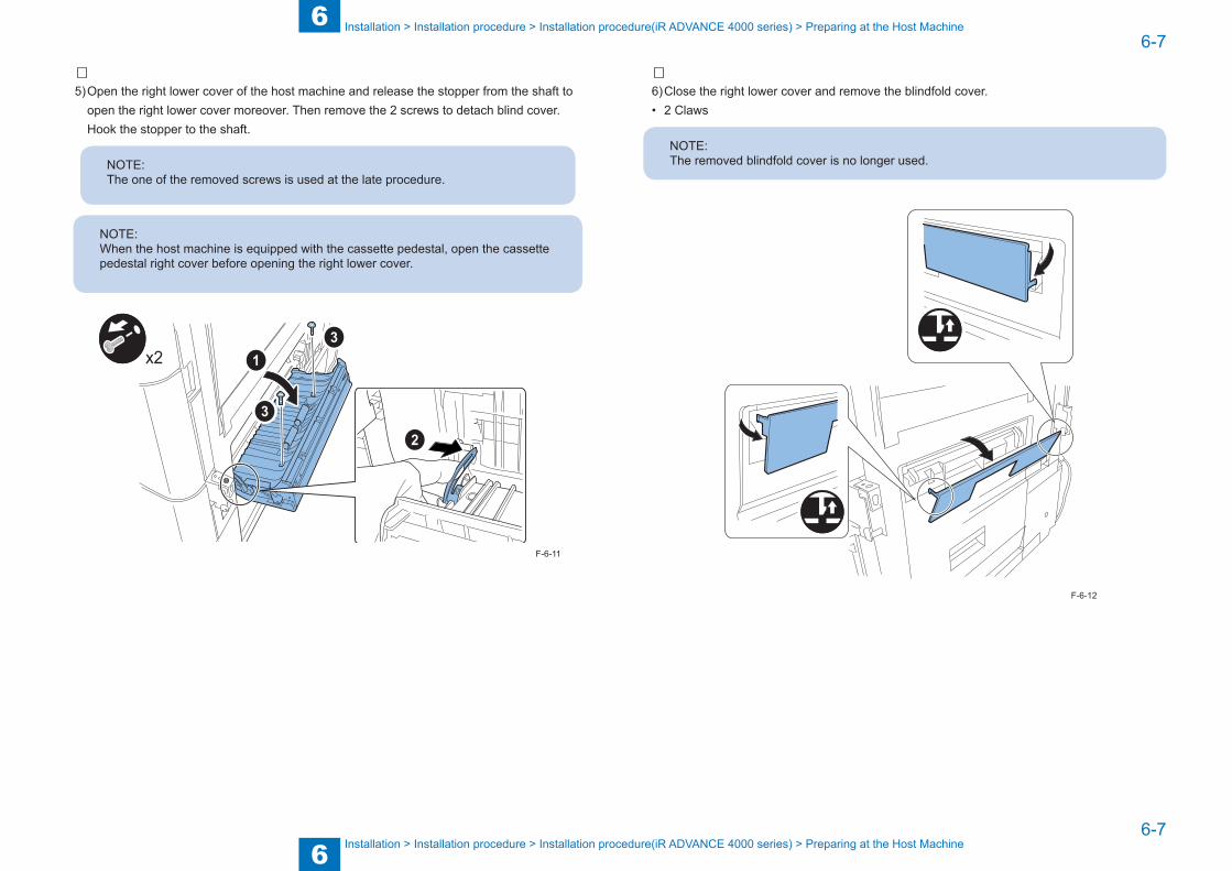
5) Open the right lower cover of the host machine and release the stopper from the shaft to open the right lower cover moreover. Then remove the 2 screws to detach blind cover. Hook the stopper to the shaft.
NOTE:The one of the removed screws is used at the late procedure.
NOTE:When the host machine is equipped with the cassette pedestal, open the cassette pedestal right cover before opening the right lower cover.
x2
F-6-11
6) Close the right lower cover and remove the blindfold cover. • 2 Claws
NOTE:The removed blindfold cover is no longer used.
F-6-12
6
66-8
6-8
Installation > Installation procedure > Installation procedure(iR ADVANCE 4000 series) > Preparing at the Host Machine
Installation > Installation procedure > Installation procedure(iR ADVANCE 4000 series) > Preparing at the Host Machine
7) Open the right lower cover and release the stopper from the shaft.8) Set the right cover guide to the position shown in the figure and hold the right cover guide.
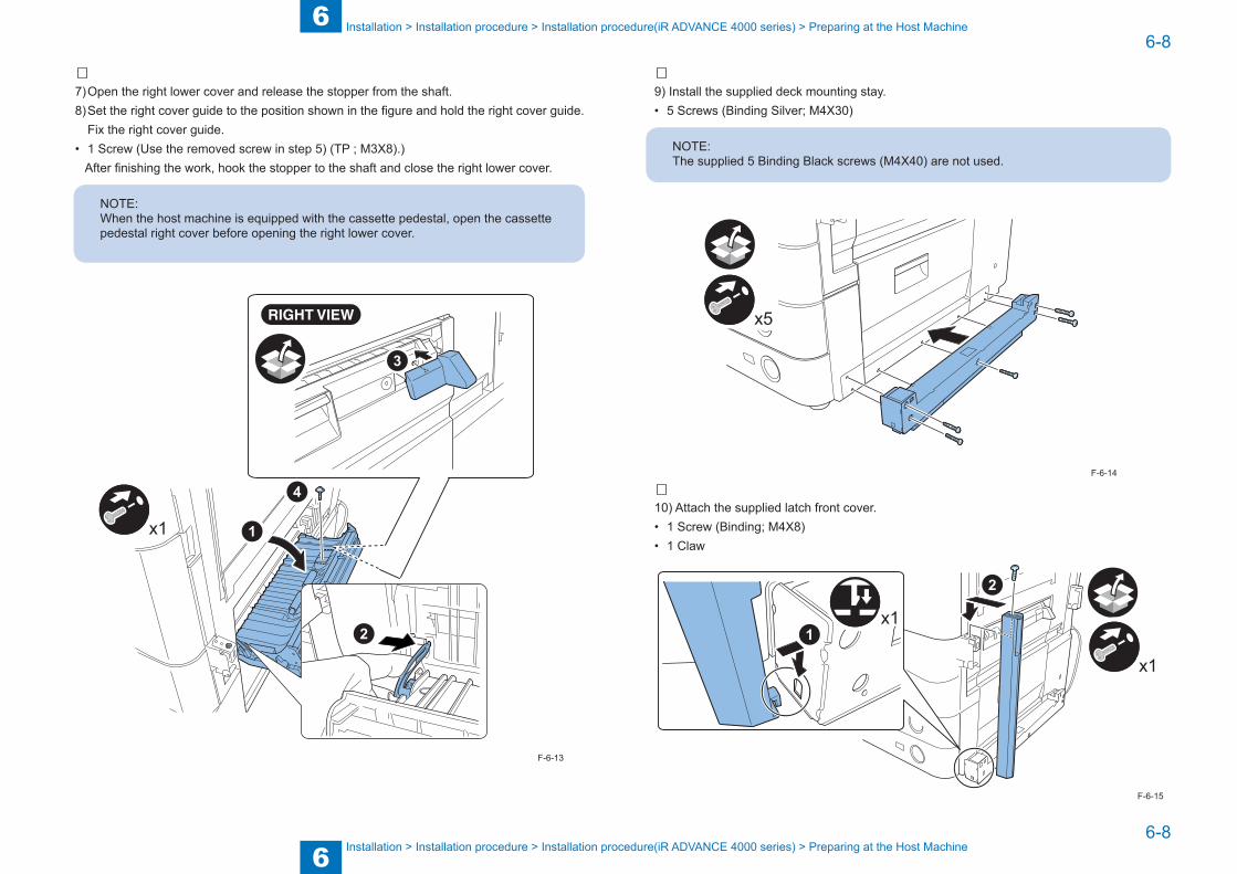
Fix the right cover guide.• 1 Screw (Use the removed screw in step 5) (TP ; M3X8).) After finishing the work, hook the stopper to the shaft and close the right lower cover.
NOTE:When the host machine is equipped with the cassette pedestal, open the cassette pedestal right cover before opening the right lower cover.
x1
F-6-13
9) Install the supplied deck mounting stay.• 5 Screws (Binding Silver; M4X30)
NOTE:The supplied 5 Binding Black screws (M4X40) are not used.
x5
10) Attach the supplied latch front cover.• 1 Screw (Binding; M4X8)• 1 Claw
x1
x1
F-6-14
F-6-15

6
66-9
6-9
Installation > Installation procedure > Installation procedure(iR ADVANCE 4000 series) > Connecting with the Host Machine and Preparing at the Paper Deck
Installation > Installation procedure > Installation procedure(iR ADVANCE 4000 series) > Connecting with the Host Machine and Preparing at the Paper Deck
■ Connecting with the Host Machine and Preparing at the Paper
Deck
1) Remove the bracket from the right side of the paper deck.• 4 Screws
NOTE:The removed screws are used later.
x4
2) Install the roller support plate at 3mm high position from the floor. • 2 Screws (Use the removed screw in step 1) (RS ; M4X8).)
F-6-16
x2
3㎜
3) Draw the deck mounting cradle, insert the positioning pin to the hole of deck mounting stay and then fix the deck mounting cradle.
• 3 Screws (Binding; M4X8)
x3
F-6-17
F-6-18
F-6-19
6
66-10
6-10
Installation > Installation procedure > Installation procedure(iR ADVANCE 4000 series) > Connecting with the Host Machine and Preparing at the Paper Deck
Installation > Installation procedure > Installation procedure(iR ADVANCE 4000 series) > Connecting with the Host Machine and Preparing at the Paper Deck
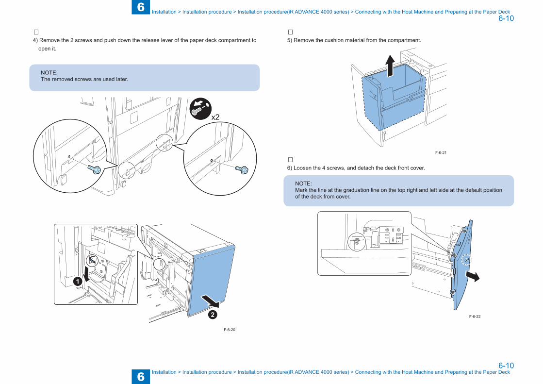
4) Remove the 2 screws and push down the release lever of the paper deck compartment to open it.
NOTE:The removed screws are used later.
x2
F-6-20
5) Remove the cushion material from the compartment.
6) Loosen the 4 screws, and detach the deck front cover.
NOTE:Mark the line at the graduation line on the top right and left side at the default position of the deck from cover.
F-6-21
F-6-22

6
66-11
6-11
Installation > Installation procedure > Installation procedure(iR ADVANCE 4000 series) > Connecting with the Host Machine and Preparing at the Paper Deck
Installation > Installation procedure > Installation procedure(iR ADVANCE 4000 series) > Connecting with the Host Machine and Preparing at the Paper Deck
7) Push the compartment, and then connect the paper deck to the host machine.
8) Loosen the 4 screws retaining the roller support plate on the front side and then set the clearance between the roller and the floor for 3mm. Tighten the 4 screws with the roller support plate.
3mm
9) Remove the paper deck from the host machine and then draw out the compartment.
F-6-23
F-6-24
10) Fit the deck front cover with the coupling of the paper level indicator; then tighten the screw while adjusting the graduation level at which you marked at step 6).
6).
NOTE:Turn the gear of the paper level indicator fully counterclockwise until it is indicated "White".
11) Connect the paper deck to the host machine
F-6-25
F-6-26

6
66-12
6-12
Installation > Installation procedure > Installation procedure(iR ADVANCE 4000 series) > Connecting with the Host Machine and Preparing at the Paper Deck
Installation > Installation procedure > Installation procedure(iR ADVANCE 4000 series) > Connecting with the Host Machine and Preparing at the Paper Deck
12) Install the 2 bottom stay covers.• 2 Screws (Binding; M4X8)
x2
13) Install the paper deck right cover.• 3 Screws (Use the screw removed in step 1) and step 4) (RS ; M3X8).)• 2 Claws
NOTE:Hook claws of the upper part of the paper deck right cover on top holes of the paper deck main unit stay. Insert the right edge to the inside of the rear cover.
x3
x2
F-6-27
F-6-28
14) Close the compartment.
15) Remove the connector blindfold plate of the host machine. (The removed plate is not used.)
16) Remove the blindfold seal at the rear side of the host machine and attach the Wire Saddle at which the seal is removed. Then clamp the cable as shown in the figure.
1
x1
F-6-29
F-6-30
6
66-13
6-13
Installation > Installation procedure > Installation procedure(iR ADVANCE 4000 series) > Connecting with the Host Machine and Preparing at the Paper Deck
Installation > Installation procedure > Installation procedure(iR ADVANCE 4000 series) > Connecting with the Host Machine and Preparing at the Paper Deck
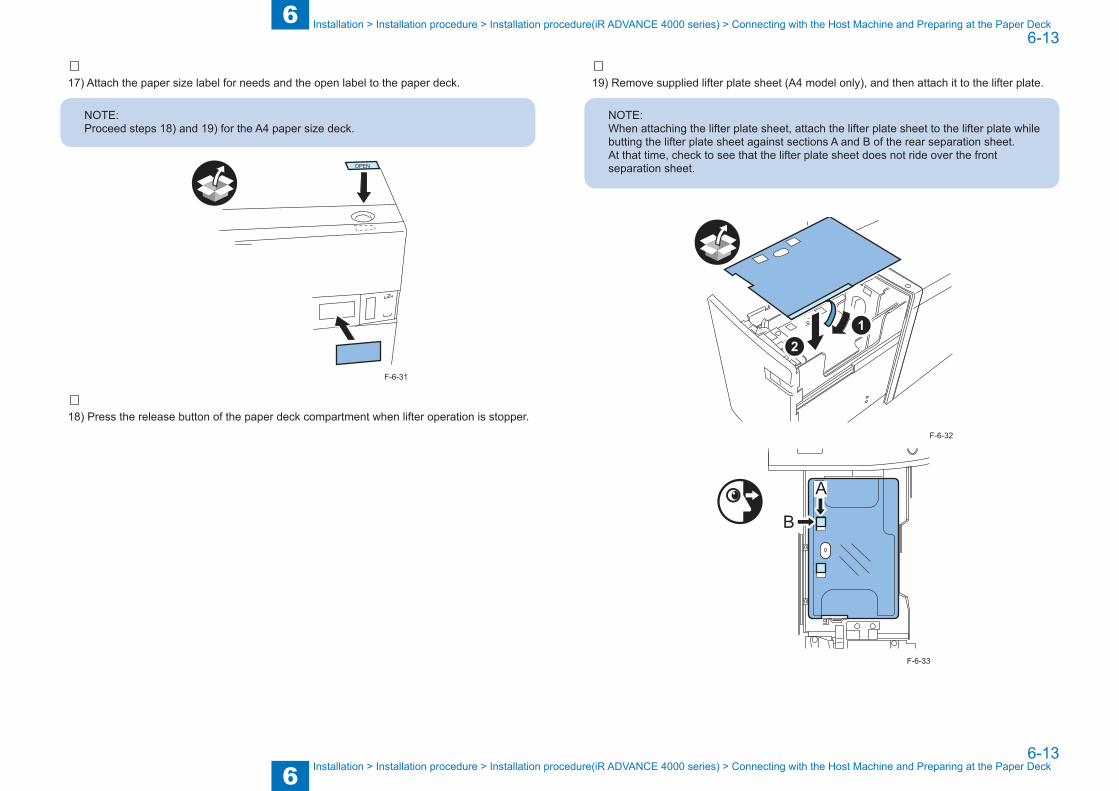
17) Attach the paper size label for needs and the open label to the paper deck.
NOTE:Proceed steps 18) and 19) for the A4 paper size deck.
OPEN
18) Press the release button of the paper deck compartment when lifter operation is stopper.
F-6-31
19) Remove supplied lifter plate sheet (A4 model only), and then attach it to the lifter plate.
NOTE:When attaching the lifter plate sheet, attach the lifter plate sheet to the lifter plate while butting the lifter plate sheet against sections A and B of the rear separation sheet. At that time, check to see that the lifter plate sheet does not ride over the front separation sheet.
A
B
F-6-32
F-6-33

6
66-14
6-14
Installation > Installation procedure > Installation procedure(iR ADVANCE C5000 series) > Preparing at the Host Machine
Installation > Installation procedure > Installation procedure(iR ADVANCE C5000 series) > Preparing at the Host Machine
■ Checking the Remaining Parts1) The following parts remain after installing the paper deck. Make sure not to leave the parts
at the site.
NOTE:After the work, proceed “Changing the Paper Size (p. 6-25)” and “Adjustment (p. 6-26)”.
C
[1] Latch catch C 2pcs [2] Binding screw (M4x40)(Black) 5pcs
[3] Binding screw (M4x8) 1pc
[4] Tapping screw (M3X8) 1pc
[5] RS-tight screw (M4X8) 1pc
[6] Blindfold cover 1pc
F-6-34
Installation procedure(iR ADVANCE C5000 series)
NOTE:Follow the installation procedure depending on the connected host machine because the procedures are different each other.-When the paper deck is connected to iR ADVANCE 4000 series, see p. 6-5.
■ Preparing at the Host Machine
1) Cut out the blindfold cover on the right rear side of the host machine using the nipper.
F-6-35

6
66-15
6-15
Installation > Installation procedure > Installation procedure(iR ADVANCE C5000 series) > Preparing at the Host Machine
Installation > Installation procedure > Installation procedure(iR ADVANCE C5000 series) > Preparing at the Host Machine
2) Open the second and first cassettes and the front cover, then remove the small right cover • 1 Screw
NOTE:The removed screw is used later.
x2
PUSH
x1
F-6-36
F-6-37
3) Cut out the upper part of the small right front cover using the nipper, and then reinstall the lower part to the original position with the screw removed at step 2).
NOTE:The removed upper part is no longer used.
F-6-38
6
66-16
6-16
Installation > Installation procedure > Installation procedure(iR ADVANCE C5000 series) > Preparing at the Host Machine
Installation > Installation procedure > Installation procedure(iR ADVANCE C5000 series) > Preparing at the Host Machine
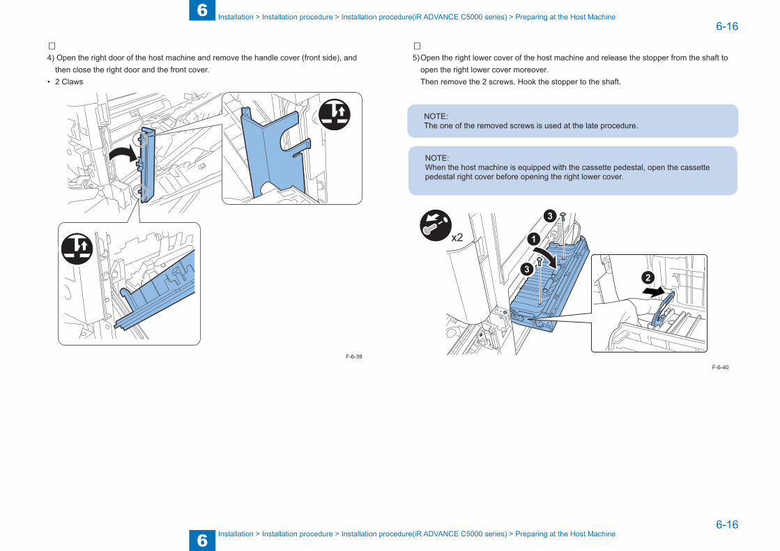
4) Open the right door of the host machine and remove the handle cover (front side), and then close the right door and the front cover.
• 2 Claws
F-6-39
5) Open the right lower cover of the host machine and release the stopper from the shaft to open the right lower cover moreover.
Then remove the 2 screws. Hook the stopper to the shaft.
NOTE:The one of the removed screws is used at the late procedure.
NOTE:When the host machine is equipped with the cassette pedestal, open the cassette pedestal right cover before opening the right lower cover.
x2
F-6-40

6
66-17
6-17
Installation > Installation procedure > Installation procedure(iR ADVANCE C5000 series) > Preparing at the Host Machine
Installation > Installation procedure > Installation procedure(iR ADVANCE C5000 series) > Preparing at the Host Machine
6) Close the right lower cover and remove the blindfold cover. • 2 Claws
NOTE:The removed blindfold cover is no longer used.
F-6-41
7) Open the right lower cover and release the stopper from the shaft.8) Set the right cover guide to the position shown in the figure and hold the right cover guide.
Fix the right cover guide.• 1 Screw (Use the removed screw in step 5) (TP ; M3X8).) After finishing the work, hook the stopper to the shaft and close the right lower cover.
NOTE:When the host machine is equipping with the cassette pedestal, open the cassette pedestal right cover before opening the right lower cover.
x1
F-6-42

6
66-18
6-18
Installation > Installation procedure > Installation procedure(iR ADVANCE C5000 series) > Preparing at the Host Machine
Installation > Installation procedure > Installation procedure(iR ADVANCE C5000 series) > Preparing at the Host Machine
9) Install the latch catch C in the position where the blindfold cover was removed at step 1).• 2 Screws (Binding; M4X8)
x2
10) Pull up the handle as shown. Then install the latch catch C in the position where the upper part of the small right front cover was removed at step 2).
• 3 Screws (Binding; M4X8)
x3
F-6-43
F-6-44
11) Open the right door of the host machine and reinstall the handle cover (front side) removed at step 4 to the original position. Then close all covers and set the cassettes into the machine.
• 2 Claws
x2
12) Install the latch catch guide on the front side of latch catch C.• 1 Screw (Binding; M4X8)
x1
F-6-45
F-6-46

6
66-19
6-19
Installation > Installation procedure > Installation procedure(iR ADVANCE C5000 series) > Connecting with the Host Machine and Preparing at the Paper Deck
Installation > Installation procedure > Installation procedure(iR ADVANCE C5000 series) > Connecting with the Host Machine and Preparing at the Paper Deck
13) Install the supplied deck mounting stay. • 5 Screws (Binding Black; M4X40)
NOTE:The supplied 5 Binding Silver screws (M4X30) are not used.
x5
14) Attach the supplied latch front cover.• 1 Screw (Binding; M4X8)• 1 Claw
x1
x1
F-6-47
F-6-48
■ Connecting with the Host Machine and Preparing at the Paper
Deck
1) Remove the bracket from the right side of the paper deck.• 4 Screws
NOTE:The two pieces of the removed screws are used later.
x4
F-6-49
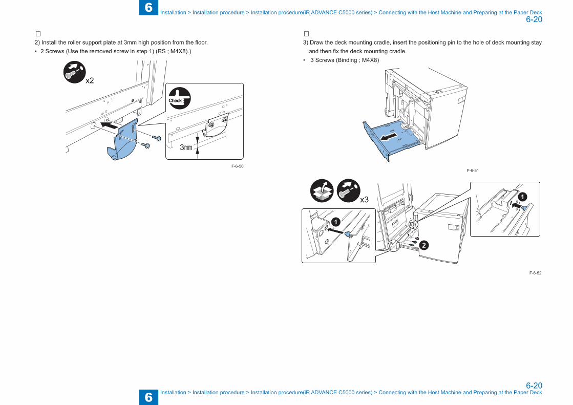
6
66-20
6-20
Installation > Installation procedure > Installation procedure(iR ADVANCE C5000 series) > Connecting with the Host Machine and Preparing at the Paper Deck
Installation > Installation procedure > Installation procedure(iR ADVANCE C5000 series) > Connecting with the Host Machine and Preparing at the Paper Deck
2) Install the roller support plate at 3mm high position from the floor. • 2 Screws (Use the removed screw in step 1) (RS ; M4X8).)
x2
3㎜
F-6-50
3) Draw the deck mounting cradle, insert the positioning pin to the hole of deck mounting stay and then fix the deck mounting cradle.
• 3 Screws (Binding ; M4X8)
x3
F-6-51
F-6-52

6
66-21
6-21
Installation > Installation procedure > Installation procedure(iR ADVANCE C5000 series) > Connecting with the Host Machine and Preparing at the Paper Deck
Installation > Installation procedure > Installation procedure(iR ADVANCE C5000 series) > Connecting with the Host Machine and Preparing at the Paper Deck
4) Remove the 2 screws and push down the release lever of the paper deck compartment to open it.
NOTE:The removed screws are used later.
x2
F-6-53
F-6-54
5) Remove the cushion material from the compartment.
6) Loosen the 4 screws, and detach the deck front cover.
NOTE:Mark line on the scale of the top right and left at which the cover is originally attached.
F-6-55
F-6-56

6
66-22
6-22
Installation > Installation procedure > Installation procedure(iR ADVANCE C5000 series) > Connecting with the Host Machine and Preparing at the Paper Deck
Installation > Installation procedure > Installation procedure(iR ADVANCE C5000 series) > Connecting with the Host Machine and Preparing at the Paper Deck
7) Push the compartment, and then connect the paper deck to the host machine.
8) Loosen the 4 screws retaining the roller support plate on the front side and then set the clearance between the roller and the floor for 3mm. Tighten the 4 screws with the roller support plate.
3mm
9) Remove the paper deck from the host machine and then draw out the compartment.
F-6-57
F-6-58
10) Fit the deck front cover with the coupling of the paper level indicator; then tighten the screw while adjusting the graduation level at which you marked at step 6).
6).
NOTE:Turn the gear of the paper level indicator fully counterclockwise until it is indicated "White".
11) Connect the paper deck to the host machine.
F-6-59
F-6-60

6
66-23
6-23
Installation > Installation procedure > Installation procedure(iR ADVANCE C5000 series) > Connecting with the Host Machine and Preparing at the Paper Deck
Installation > Installation procedure > Installation procedure(iR ADVANCE C5000 series) > Connecting with the Host Machine and Preparing at the Paper Deck
12) Install the 2 bottom stay covers.• 2 Screws (Binding; M4X8)
x2
13) Install the paper deck right cover.• 3 Screws (Use the screw removed in step 1) and step 4) (RS ; M3X8).)• 2 Claws
NOTE:Hook claws of the upper part of the paper deck right cover on top holes of the paper deck main unit stay. Insert the right edge to the inside of the rear cover.
x3
x2
F-6-61
F-6-62
14) Close the compartment.
15) Remove the connector blindfold plate of the host machine. (The removed plate is not used.)
16)Remove the blindfold seal at the rear side of the host machine and attach the Wire Saddle at which the seal is removed. Then clamp the cable as shown in the figure.
x1
F-6-63
F-6-64

6
66-24
6-24
Installation > Installation procedure > Installation procedure(iR ADVANCE C5000 series) > Connecting with the Host Machine and Preparing at the Paper Deck
Installation > Installation procedure > Installation procedure(iR ADVANCE C5000 series) > Connecting with the Host Machine and Preparing at the Paper Deck
17) Attach the paper size label for needs and the open label to the paper deck.
NOTE:Proceed steps 18) and 19) for the A4 paper size deck.
OPEN
18) Press the release button of the paper deck compartment when lifter operation is stopper.
F-6-65
19) Remove supplied lifter plate sheet (A4 model only), and then attach it to the lifter plate.
NOTE:When attaching the lifter plate sheet, attach the lifter plate sheet to the lifter plate while butting the lifter plate sheet against sections A and B of the rear separation sheet. At that time, check to see that the lifter plate sheet has not ridden over the front separation sheet.
A
B
F-6-66
F-6-67
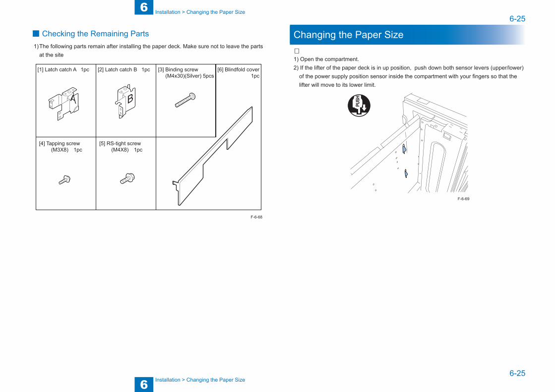
6
66-25
6-25
Installation > Changing the Paper Size
Installation > Changing the Paper Size
■ Checking the Remaining Parts1) The following parts remain after installing the paper deck. Make sure not to leave the parts
at the site
BA
[1] Latch catch A 1pc [2] Latch catch B 1pc [3] Binding screw (M4x30)(Silver) 5pcs
[4] Tapping screw (M3X8) 1pc
[5] RS-tight screw (M4X8) 1pc
[6] Blindfold cover 1pc
F-6-68
Changing the Paper Size
1) Open the compartment.2) If the lifter of the paper deck is in up position, push down both sensor levers (upper/lower)
of the power supply position sensor inside the compartment with your fingers so that the lifter will move to its lower limit.
F-6-69

6
66-26
6-26
Installation > Adjustment > Adjusting the Left Edge Margin > For iR ADVANCE C5000 series
Installation > Adjustment > Adjusting the Left Edge Margin > For iR ADVANCE C5000 series
3) Remove the 1 screw, and mount the paper rear end guide plate to suit the new paper size.4) In the same way, remove the screw for each, and adjust the position of the left/right guide
plates to suit the new paper size.
NOTE:If the size is set to LTR, it is unnecessary to use the rear end guide plate. To find out the paper size, check the mark on the bottom plate.
x3
5) In service mode, set the new paper size: LEVEL1/COPIER>OPTION>ACC>DK-P.
-When the host machine is iR ADVANCE 4000 series: 0: A4, 2: LTR-When the host machine is iR ADVANCE C5000 series: 0: A4, 1: LTR
NOTE:After you have changed the paper size, be sure to turn off and then on the host machine.
Adjustment
Adjusting the Left Edge Margin ■ For iR ADVANCE 4000 series
1) Check to make sure that the 2 adjusters of the pedestal of the host machine are in contact with the floor.
2) Turn on the host machine.3) Check to see that the paper deck is used as the paper feeding and the operation is correct.4) Make copies/prints of the test image, and check the output images to see that the left edge
margin of the paper deck is the standard: within 2.5 +/- 1.5 mm. Otherwise, perform the following:
<Left Edge Margin Adjustment of Paper Deck>4-1) Set the host machine to the service mode (LEVEL 2) and select “DK-ADJ-Y”.
LEVEL2/COPIER>ADJUST>MISC>DK-ADJ-Y4-2) According to the test image, change the input value.
As the value is changed by 1, the left edge margin is increased or decreased by 0.1 mm.+: Left margin becomes larger. (An image moves to the right.)-: Left margin becomes smaller. (An image moves to the left.)
4-3) After the completion of the adjustment, exit the service mode.
■ For iR ADVANCE C5000 series
1) Check to make sure that the 2 adjusters of the pedestal of the host machine are in contact with the floor.
2) Turn on the host machine.3) Check to see that the paper deck is used as the paper feeding and the operation is correct.4) Make copies/prints of the test image, and check the output images to see that the left edge
margin of the paper deck is the standard: within 2.5 +/- 1.5 mm. Otherwise, perform the following:
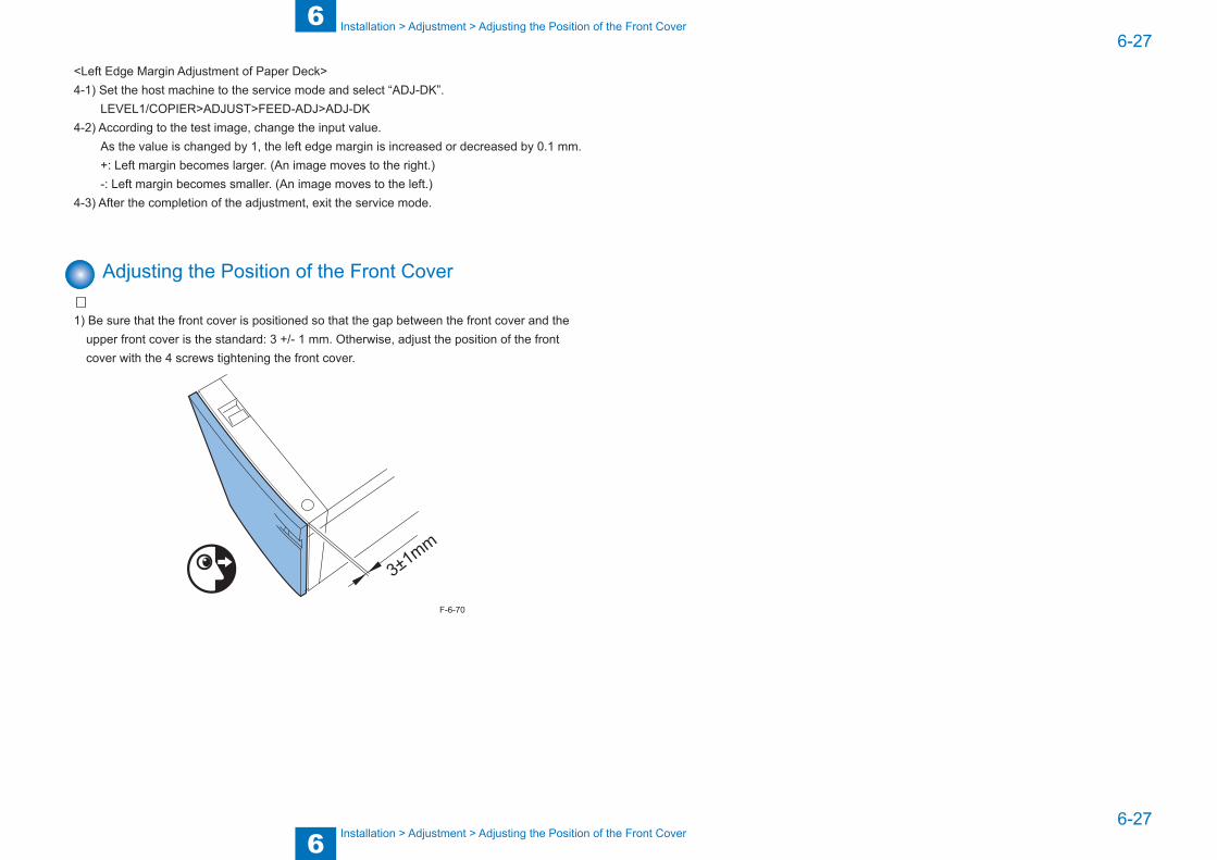
6
66-27
6-27
Installation > Adjustment > Adjusting the Position of the Front Cover
Installation > Adjustment > Adjusting the Position of the Front Cover
<Left Edge Margin Adjustment of Paper Deck>4-1) Set the host machine to the service mode and select “ADJ-DK”.
LEVEL1/COPIER>ADJUST>FEED-ADJ>ADJ-DK4-2) According to the test image, change the input value.
As the value is changed by 1, the left edge margin is increased or decreased by 0.1 mm.+: Left margin becomes larger. (An image moves to the right.)-: Left margin becomes smaller. (An image moves to the left.)
4-3) After the completion of the adjustment, exit the service mode.
Adjusting the Position of the Front Cover
1) Be sure that the front cover is positioned so that the gap between the front cover and the upper front cover is the standard: 3 +/- 1 mm. Otherwise, adjust the position of the front cover with the 4 screws tightening the front cover.
3±1mm
F-6-70

Appendix ■Service Tools ■General Circuit Diagram ■Signal Name List
7
7ii
ii
Appendix > Service Tools
Appendix > Service Tools
Service Tools ■ Solvents and Oils
Name Uses Composition RemarksAlcohol Cleaning; e.g.,
Glass, plastic, rubber; external covers
Fluoride-family hydrocarbonAlcoholSurface activating agentWater
Do not bring near fire.Procure locally.Substitute: IPA (isopropyl alcohol)
Solvent Cleaning; e.g., Metal; oil or toner stain.
Fluoride-family hydrocarbonChlorine-family hydrocarbonAlcohol
Do not bring near fire.Procure locallySubstitute: MEK (methyl ethyl ketone)
■ Special Tools• None
T-7-1

iii
iii
App
endi
x >
Gen
eral
Circ
uit D
iagr
am
App
endi
x >
Gen
eral
Circ
uit D
iagr
am
General Circuit Diagram ■ General Circuit Diagram (1/1)
12345678910
12345678910
F
E
D
C
B
A
F
E
D
C
B
A
M
B13A13 8
M
CLSL
SL
LED
SW
_LE
DO
N
GN
D
PAP
_TO
P_S
EN
S
LIFT
_M_U
PLM
T
PAP
_SE
NS
GN
D
GN
D
GN
D
24V
U24
VU
PIC
KU
P_S
L_O
N*
GN
D
FEE
D_S
EN
S
GN
D
24V
U
P_O
UT_
SE
NS
PAP_VL_EMP_U
5V
PAP_VL_EMP_L
LIFT
_LO
W_L
MT
GN
D
LIFT
_M_U
P
5V
RX
EN
D
GN
D
RX
DAT
A*
SIC
LOC
K
TXLO
AD
TXD
ATA
*
RX
OU
TEN
*
24V
R
FEE
D_M
_A
24V
R
DE
CK
_LO
CK
OFF
_SL_
ON
*5V5V
24V
U
GN
D
DE
CK
_MO
UN
T_S
EN
S
5V 5VDE
CK
_OP
EN
_SE
NS
GN
D
FEE
D_M
_A*
LIFT
_M_D
OW
N
LIFT_M_DOWN
GN
D
LIFT
_LO
W_L
MT
LIFT_M_UP
5V
PAP
_VL_
EM
P_L
GND
PAP
_VL_
EM
P_U
5VP_O
UT_
SE
NS
5V
PU
LL_C
L_O
N*
24V
U
5V
GN
D
5VFEE
D_S
EN
S
GN
D
FEE
D_C
L_O
N*
PIC
KU
P_S
L_O
N*
24V
U5V5V5V
GN
D
5V 5V 5V
GN
D
GN
D
PAP
_SE
NS
LIFT
_M_U
PLM
T
PAP
_TO
P_S
EN
S
GN
D
5V GN
D
DE
CK
_OP
EN
_SW
DE
CK
_OP
EN
_SW
24V
OU
T
24V
IN
GND
FEED_CL_ON*
GN
D FEE
D_M
_B*
FEE
D_M
_B*
LED
SW
_LE
DO
N
24V
5V
MT1
1 2 3 4 5 6 7 8
J7050B
1234567 J123 1 J3
2 3 41
J7050
1234
J19D
3 2 1
PS1D
3 2 1
PS6D
3 2 1
PS4D
3 2 1
PS3D
123
PS2D
J18H
12
J18D
3 2 1J12
1 2 3J26
1 32J7
1
2
SL2D
21J27F
2 31 J31
4 3 2 1 J20
81 2 3 4 5 6 7 9 10J22M
1097654321 8J22F
81 2 3 4 5 6 7 9 10J4
2
1
SL1D 2
1
CL2D
2
1
M2D
123
PS5D
3 2 1
PS9D
J6
21
SW1D
21
SW
3D
21
LED
1
1 2 3 4 J19L 123J23
1 2
J16L
21 J18L
J5H
10982 3 4 5 61 7J10L
12
J16DJ16H
123J17
123
J29
21
J28L
1413121110982 3 4 5 61 7 J15L
J15H
14 13 12 11 10 9 8 23456 17
J15DJ19HJ10H
13
10 9 8 23456 17
J10D
1
J5A J5B
3 2 1
PS7D
123
PS8D
3 2 1J24
123
J25L
J25H
321J25D
21
J27M
12
J28D
J28H
6 7 8
3 2 1
J30
5432
654321
M1D
1 2
SW2D
21 3 4 875 6
10
9
11 12 13
1 2 3 54 8 976 10 1 1 12
123
J14123
J133 2 1
J11
3 4 5 61 2 J2
Deck Contoroller PCB
Deck Feeder Sensor
Deck Set Sensor
Deck Open Sensor
Deck Pickup Sensor
Deck Paper Level Sensor
Deck Paper Replenishing
Position Sensor
Deck Lifter Position Sensor
Deck Pickup Roller Release Solenoid
Deck Pickup Clutch
Deck Open Solenoid
Deck Lifter Motor
Deck Lifter Lower Limit
Sensing Switch
Deck Main Motor Deck Open Sensing Switch
Cassette Heater Unit
Open Switch PCB
Deck Paper-Out Sensor
Deck Lifter Upper Limit
Sensor
F-7-1

iv
iv
Signal Name List
Jack No. Pin No Abbreviated Signal Name Signal NameJ1 1 RXOUTEN*
2 TXDATA*3 TXLOAD4 RXDATA*5 RXEND6 GND GND7 SICLOCK
J2 1 FEED_M_B Deck main motor B (M1)2 24VR 24VR3 FEED_M_B* Deck main motor B*(M1)4 FEED_M_A Deck main motor A (M1)5 24VR 24VR6 FEED_M_A* Deck main motor A*(M1)
J3 1 5V 5V2 24V 24V3 GND GND
J4 1 GND GND2 PAP_VL_EMP_U Deck paper replenishing position sensor
signal(PS8)3 5V 5V45 PAP_VL_EMP_L Deck paper level sensor signal(PS7)6 5V 5V7 LIFT_LOW_LMT Deck lifter lower limit sensing switch
signal(SW2)8 GND GND9 LIFT_M_UP Deck lifter motor UP signal(M2)10 LIFT_M_DOWN Deck lifter motor DOWN signal(M2)
J5A 1 LEDSW_LEDON Deck open indication signal(LED1)2 5V 5V3 GND GND4 DECK_OPEN_SW Deck open switch signal(SW3)5 GND GND6 PAP_SENS Deck paper-out sensor signal(PS2)7 5V 5V8 GND GND9 LIFT_M_UPLMT Deck lifter upper limit sensor signal(PS3)10 5V 5V11 GND GND12 PAP_TOP_SENS Deck lifter position sensor signal(PS4)13 5V 5V
J5B 1 24VU 24VU2 PICKUP_SL_ON* Deck pickup roller release solenoid
signal(SL1)3 GND GND4 FEED_SENS Deck pickup sensor signal(PS6)5 5V 5V6 24VU 24VU7 PULL_CL_ON*8 GND GND9 P_OUT_SENS Deck feeder sensor signal(PS1)10 5V 5V11 24VU 24VU12 FEED_CL_ON* Deck pickup clutch signal(CL2)13 - -
J6 1 24VU 24VU2 DECK_LOCKOFF_SL_ON* Deck open solenoid signal(SL2)3 GND GND4 DECK_MOUNT_SENS Deck set sensor signal(PS5)5 5V 5V6 GND GND7 DECK_OPEN_SENS Deck open sensor signal(PS9)8 5V 5V
J7 1 24VOUT 24VOUT2 - -3 24VIN 24VIN
T-7-2