direct conversion for space solar power - nasa's … · direct conversion for space solar...
TRANSCRIPT

Direct Conversion for Space Solar Power
Nicholas Boechler, advisor Dr. Narayanan Komerath
School of Aerospace Engineering, Georgia Institute of Technology, Atlanta GA 30332 [email protected]

Table of Contents: A. Introduction pg. 1 B. Project Goals pg. 2 C. Road Blocks to Space Solar Power pg. 3 D. Applicable Technologies Survey and Analysis pg. 5 E. System Designs pg. 8 F. Applications pg. 22 G. Conclusion pg. 24 H. Bibliography pg. 25

A. INTRODUCTION: Space Solar Power (SSP) is a powerful yet nearly untapped resource with revolutionary potential. SSP systems currently have several roadblocks to their implementation. With the technology in use today, converting solar power to useable energy is inefficient, the required converters have a large mass per unit power, and launching those converters is expensive. More fundamentally, in all current SSP systems, energy must be converted to DC before being converted again into whatever form is necessary. If techniques could be discovered for converting broadband sunlight directly to a useable narrowband application dependent frequency, many fundamental breakthroughs in aerospace endeavors can be achieved. This project studied a large number of options that might lead to direct conversion. Those technology options were analyzed according to which would warrant further exploration from the point of view of aerospace systems applications and possible mass per unit power. Estimates of the possible mass per unit power of potential direct conversion systems were made, and future applications that would benefit from those direct conversion systems were identified. Three possible concepts were developed to various stages of maturity depending on the simplicity and feasibility of the concept. Initially a concept was developed based on W.C. Brown’s and ITN Energy System’s, microwave and optical rectenna work respectively [1,2,3]. Basically, solar radiation is coupled to a thin film nanofabricated antenna array including either rectification components or THz sampling for wave reconstruction. The system is estimated to have a possible specific power of 4.658 kW/kg, which is a 1763% increase over traditional photovoltaics. The next two concepts use solar sail-like parabolic reflectors to focus large amounts of sunlight onto a medium. In one concept the medium is a dielectrically modulated shocked photonic crystal based on the work of Dr. Joannopoulos that can linearly shift the frequency and simultaneously narrow the band. The last concept incorporates a medium of low density molecular vapor contained in cylindrical resonator tube constructed from solar sail material producing a non-linear emission similar to naturally occurring astronomical MASERs. This MASER system is estimated to have a specific power of 3.539 kW/kg, which is a 1415% improvement over traditional photovoltaics. There are several applications that would benefit from direct conversion systems. Most obviously would be a SSP grid. Direct conversion systems are estimated to cut the cost of launching a satellite with equivalent power output to approximately 5-7% of the cost. Additionally, the variability of the possible output allows for higher frequency transmissions that cause less beam spreading and subsequently less ground based infrastructure. Electric propulsion systems would also benefit directly by drastically reducing on board mass both from higher specific power and direct conversion to the necessary ionization frequency. Additionally the inclusion of solar sail allows for possible hybridization. As with any sufficiently advanced concept, it is impossible to know for sure where the problems, roadblocks, and successes may lie in the future. This said, each of the major concepts described has been justifiably proven to warrant further exploration and study based on their revolutionary potential. They are a true shift from the paradigm of conventional SSP.
1

B. PROJECT GOALS: When the “Direct Conversion for Space Solar Power” project was proposed in May of 2005 several project goals were outlined as follows in order to narrow the scope of this rather large undertaking: B1. Identify Applicable Technologies: Explore large number of options that might lead to direct conversion. One solution might not be the answer, so several types of conversion technology must be explored. B2. Analyze for Aerospace Applications: In preliminary review of this field, it has become evident that there has been not much attention paid to high power/low mass systems. Even after finding a technology that would warrant further exploration, it must be looked at from the point of view of aerospace systems applications and possible mass per unit power. B3. Estimate Specific Power: Provide a justifiable estimate of mass per unit power of future direct conversion systems. B4. Future Applications: Identify possible future applications that would benefit from direct conversion technology.
2

C. ROADBLOCKS TO SPACE SOLAR POWER: Since the development of SSP as a concept there have been several practical and technological roadblocks that have prohibited its implementation. The two most critical problems, which play into and further cause other areas of difficulty, are the nature of current photovoltaic technology itself and high launch costs. C1. Photovoltaic Solar Cell Technology: The current method for solar power generation is based upon essentially the same technology as the original silicon photovoltaic cells. These cells work by using photons to excite electrons in a semiconductor to produce an electric current. This method is fundamentally limited for several reasons. Sunlight is broadband energy and only photons with certain energy can dislodge an electron. To become part of the circuit the electron must jump a band gap specific to the material. All the energy put into jumping this band gap is converted to waste heat. Because of this, traditional photovoltaic cells already have around a 55% theoretical efficiency loss [4]. In addition, photovoltaic cells produce only direct current, and consideration must be taken that many space applications require EM radiation or other waveform currents. This re-conversion system would require extra mass and add an extra factor for efficiency loss, compared to something that already has an outgoing alternating current. The table below specifies a range of solar cell performance values from literature. Note of course that some claims made are not necessarily practical, but for the purpose of comparison and wide range has been listed. Table 1: Data on Solar Cell Performance: Solar Cell Performance Thick Film Thin Film Efficiency ~25-40% ~10-20% Specific Power ~.05-.25 kW/kg ~.05-.25 kW/kg Power Density ~.1-.4 kW/m2 ~.1-.4 kW/m2
References: [5,6,7,8] Note: There are some claims for higher specific power thin film solar cells for space (1-1.4 kW/kg) [6]. C2. High Launch Costs: Probably the most critical roadblock to a presence in space is high launch costs. Because of this, when dealing with SSP systems the specific power of a system is make or break for the success of the system as a whole. This can be magnified even further to the point that a SSP satellite with a given high specific power may not be able to recuperate its launch costs from power sales over its lifetime, therefore making it cost prohibitive. This launch cost problem is also further exasperated by conventional re-supply and stabilization problems. More specifically, with a large number of SSP satellites in orbit, they will have to be continually adjusted to be kept in their orbit due to solar pressure, orbital decay, and any other destabilizing factors. Thus the launch cost for launching additional propellant must also be taken into consideration, perhaps further decreasing the necessary specific power. Some current prices for low earth orbit launches [9]:
3

Table 2: LEO Launch Prices Booster 2004 Cost ($ millions) Payload to LEO (kg) $/kg Atlas 5 551 125.1 20,050 6239.4 Delta 4 Heavy 193.4 25,800 7496.12 Space Shuttle 284 24,400 11639.3 Titan 4B 491.6 21,680 22675.3 References: [9]
4

D. APPLICABLE TECHNOLOGIES SURVEY AND ANALYSIS: The initial phase of the project was to explore a large number of technological options that might lead to direct conversion. These options were then analyzed in terms of efficiency, specific power, and feasibility. It is worthwhile to note that while many of these technologies for one reason or another was not focused upon in the later stages of the project, many still have a fundamental aspect that lends to possibly solving the direct conversion problem and should be kept in mind for future exploration. D1. Signal Processing Solutions: Signal processing solutions would initially seem to be the most obvious solution to frequency conversion, but unfortunately none are very efficient or much of an improvement from the existing photovoltaics plus microwave transmitter system. Assuming broadband sunlight could be rectified, a configuration of diodes in the form of a mixer powered by an oscillator could achieve a frequency shift. The output would be the sum and difference of the input and oscillator frequencies, one of which would need to be filtered out. The oscillator would also require its own power source. Aside from the need for an undetermined quantity of power to be supplied to the oscillator, this system would be inherently inefficient due to the incorporation of a filter, and it doesn’t take into account that you would be dealing with an initial broadband current. Other options include modulating the input signal with an RF signal, which is very inefficient. In addition there are many products on the market today that provide a small range of frequency translation such as SAW filter circuits and international AC converters, but again these have a very low translation range and efficiency. Tube, Cyclotron, and Magnetron type devices also fall into this category. These devices fundamentally work by producing an EM field by crossing a magnetic field with electrons produced by a DC power supply from a cathode to anode. These devices are the current and most common way of producing microwave radiation. There are several problems however with this setup in relation to SSP systems. These problems include mechanical tolerances, scaling problems, quality decay over time, weight, impedance mismatching, and breakdown fields. Most of these problems get amplified the higher frequency output attempted, further decreasing the efficiency. These higher frequency issues would be especially pertinent to this application considering many of the applications depend on beam spreading during transmission which is minimized at higher frequencies. In addition the whole concept of direct conversion strives to eliminate just this type of DC to AC step. D2. Rapidly Ionizing Plasma: Studies have shown that an interaction between EM radiation and rapidly ionizing plasma can cause a frequency up-shift. It was also discovered that there is a simultaneous frequency down-shift [10], which seems particularly applicable. However, it would be difficult to develop a viable concept considering that a large amount of energy would be required to continually re-ionize the plasma. D3. Nanofabricated Antennae: EM radiation of lower frequencies (microwave and lower) have traditionally been generated and then transmitted through antennae in the classical sense. EM
5

radiation of higher optical frequencies has been more difficult because of decreasing size to the realm where quantum mechanics must be taken into consideration. Developing a beam in the optical frequencies has been accomplished by LASERs but is somewhat inefficient due to the population inversion. If nanofabricated antennae were possible perhaps the induced current could be downshifted slightly to a lower, application dependent frequency and re-emitted as a focused optical beam in a more classical physics manner. This is theoretically possible considering that ITN claims that it can be done with its optical rectenna [3]. Although ITN is doing it in the other direction by absorbing the radiation, it should be theoretically possible to symmetrically re-emit it in a similar fashion with tailored geometry for the emission of a focused beam. D4. Optical Resonators: Optical resonators take broadband light and convert it to an amplified narrow band. Resonators have a clear benefit to applications needing EM radiation amplification, but also might be used in direct frequency conversion. There is a Jet Propulsion Lab proposal for a toroidal or disk-like optical resonator made of an optically non-linear material for parametric frequency conversion [11]. In addition, one of the main benefits of resonators in general is the simplicity and low weight. A simple resonator can be made out of two parallel plates of reflective material. However, resonators in general have the critical drawback that they work by amplifying the resonant frequency and rejecting the non-resonant frequency, thereby implying an energy and efficiency loss. D5. Optical Rectenna: An optical rectenna is an antenna that couples with and rectifies optical radiation to DC. According to antenna theory, antenna length will scale linearly with the wavelength of the incoming radiation [3]. The theory is that a antenna array of certain scale can capture radiation of wavelengths greater that the smallest dipole resolution of the array but no greater than the size of the whole array, much in a manner similar to a Fourier transform. It is believed that a correctly designed and constructed antenna array could absorb solar radiation with 100% efficiency [3]. For broadband solar radiation the antenna would be an array of tiny half-wave dipoles, corresponding to wavelengths of approximately 2-0.3 µm [3]. At this scale the rectenna could also couple with other radiation sources such as albedo encountered by planetary passes or Jupiter’s radiation belts. The incident radiation induces a waveform current into the antenna array which would be traditionally converted to DC by a non linear element such as a diode. This concept will be further explored in system designs. D6. Shocked Photonic Crystals: In 2003 a group at MIT used a simulation to show that non-relativistic reversed Doppler Shift with near 100% efficiency in light occurs when light is reflected from a moving shock wave propagating through a photonic crystal. The system potentially offers tunable pulse rate and carrier frequency based upon artificial band gap size and can narrow the bandwidth of the incident radiation. After a significant amount of iterations light could be dramatically shifted in frequency. It was proposed that a similar system be used in micro-electrical-mechanical devices [12,13,14]. This technology will be utilized and further described in the direct conversion initial system designs. D7. Solar Pumped LASERs and MASERs: Respectively, the acronyms stand for Light or Microwave Amplification by Stimulated Emission. Both function in essentially the same way. Energy from the pumping mechanism, which is solar radiation in this case, causes excited states in the molecules of the gain medium. Enough excitation causes a population inversion and the
6

emission of EM radiation as the particle falls to a lower energy state. One important difference between MASERs and LASERs is that LASERs utilize electro-optical transitions while MASERs use ro-vibrational transitions. A critical argument can be made that because of scale that MASER transitions should be much easier to control and therefore potentially more efficient. This concept is well suited for direct conversion in that a broadband energy source can be re-emitted non-linearly in a narrowband form. The big drawback is that there is a fundamental inefficiency associated with population inversion that remains to be seen to what extent it can be minimized. These concepts will also be incorporated into later design concepts.
7

E. SYSTEM DESIGNS: E1. Optical Rectenna System: E1a. History and Background: In the 1960’s W.C. Brown pioneered the field of wireless power transmission with his work on microwave rectennae. He successfully developed a helicopter powered by a microwave rectenna [1,2]. The rectenna demonstrated efficiencies from 85-91%. It had directive properties similar to the half-wave dipole in that there was little variation in capture efficiency based on the angle of incidence of the incoming radiation. His design for a light weight and flexible thin film etched circuit rectenna weighed approximately .25 kg/m2 [2].
Figure 1: Photo W.C. Brown’s Thin Film Etched Circuit Rectenna
Reference: [2]
Figure 2: Diagram of W.C. Brown’s Thin Film Etched Circuit Rectenna
Reference: [2]
In 2002 ITN Energy Systems published its work on optical rectennae. The design consisted of an antenna array and a high frequency metal-insulator-metal diode to rectify the AC field across the antenna to DC power. ITN estimated theoretical conversion efficiencies greater than 85%. For antennae on the optical scale, ITN found that a majority of the energy in the surface modes is carried in the dielectric above the antenna so surface losses must be taken into consideration. Also the antenna must be designed to couple with a complex, broadband waveform. Unfortunately only 1% efficiency was actually achieved during testing which can be attributed at least partially to problems associated with early stages of nanofabrication. [1] E1b. Estimate: Simply based off of cited numbers from W.C. Brown and ITN [1,2,3], and estimate for a SSP system incorporating an optical rectenna can be made. ITN cited a range of theoretical coupling efficiencies of 85-100%. Taking the low end of this range, using W.C.
8

Brown’s estimated weight for a thin film etched circuit rectenna, and assuming an average solar energy density of 1.37 kW/m2 gives the following attributes:
Power Density = 1.165 kW/m2 Specific Power = 4.658 kW/kg
Comparing against the upper end of the range of data cited in table 1 for photovoltaic specific power shows that an optical rectenna could provide a 1763% increase in specific power over conventional photovoltaics. It must be noted that this estimate, as all other estimates in this paper, have a large uncertainty that highly depends on which end of the ranges are used. Because of this, finding a specific uncertainty value would be unproductive. However, the estimate can still serve as an example as to the providence of the concept. In addition these estimates generally take values at the end of the ranges in favor of traditional photovoltaics. E1c. Problems and Possibilities: The major problem with an optical rectenna with respect to direct conversion is that although you may be able to couple to the radiation, it is still a broadband waveform until it is rectified. Once the induced current is rectified, it becomes DC, and there will be the same initial problem; that the current must be re-oscillated which requires mass, energy, and a loss of efficiency. For the purposes of this project it would not be a true direct conversion system. A possible solution is that the incoming broadband radiation could be filtered at least at the highest incident frequency or preferentially even a multiple of the highest frequency, and then additively restructured to form a lower frequency signal. It would be effectively similar to a Fourier Approximation. This concept is roughly demonstrated in figure 3. Once formed into a lower frequency wave it could be retransmitted using a simple microwave antenna such as is used in many current applications.
Low Frequency Wave Approximation with High Frequency Broad Band Sampling
-1.5
-1
-0.5
0
0.5
1
1.5
0 10 20 30 40 50 60
Time
Am
plitu
de
Target f=f0
f=8*f0
f=4*f0
f=2*f0
f=f0
f=3*f0
Approximation
Figure 3: Rough 5 Term Low Frequency Sine Wave Approximation with Sampling at 2x the
Highest Frequency, Inducing Polarity Shifts at Axis Crossings
9

Another benefit given a high enough sampling rate and the ability to process data at that speed would be a tunable signal. This would be extremely important when trying to adapt the same overlying concept to various applications that have their own application dependent frequency. Also, a system with a central sampling system would entail significantly less mass and complexity without the need for incoming wavelength scale rectification components such as dispersed filters and diodes. This could potentially increase both efficiency and specific power. It is also important to note that the optical rectennae should still be seriously considered with respect to conventional space solar power without the need for THz sampling. Just based off the specific power improvement, if SSP concepts utilizing microwave generators had their standard photovoltaics replaced with optical rectennae, it might improve the system to the point where it is actually feasible. Optical rectennae could possibly also be applied to more futuristic concepts, some of which are detailed further in this report. For instance in the case of a problem with direct sunlight pumipng, an optical antenna grid could be used to pump a LASER for re-transmission using the broadband signal. Despite this possibility, the reasoning was made that if any LASER or MASER type device could be pumped by a broadband signal from an antenna array, then it should still be able to be as easily pumped directly by sunlight focused by a parabolic reflector. This reflector could be built out of solar sail type material and would be theoretically lighter and significantly easier to construct than a nanofabricated optical antenna. E2. Shocked Photonic Crystal System: E2a. Overview: A paper by Dr. Joannopoulos at MIT describes a simulation that shows that radiation traveling through a shocked photonic crystal will undergo a frequency shift while simultaneously narrowing the bandwidth [12,13]. This effect fits the goal of direct frequency conversion and narrowing of bandwidth perfectly.
Figure 4: Simulation of Frequency Shift in Shocked Photonic Crystal by Dr. Joannopoulos
Reference: [13]
10

The overall concept of photonic crystals and their applications is described in Dr. Joannopoulos’ book “Photonic Crystals: The Road from Theory to Practice [14].” Essentially he explains that photonic crystals can be fabricated on the nano-scale and through the creation of the correctly placed defects and tailored geometry can create perfect resonant cavities or waveguides depending on the design of the crystal structure. The efficiency of such devices largely depends on the quality of fabrication, but simulations show near 100% efficiency in theory [12,13,14].
Figure 5: Model of 3D Photonic Crystal by Dr. Joannopoulos
Reference: [14]
E2b. Shocked Photonic Crystal Direct Conversion Concept: The proposed photonic crystal direct conversion system uses an ultra-light parabolic reflector, probably very similar to a solar sail to focus as much solar radiation as possible through the photonic crystal. As the radiation passes through the shocked crystal the broadband solar radiation is shifted down in frequency and the band is narrowed.
Figure 6: Initial Photonic Crystal Direct Conversion Concept Visualization
11

E2c. Estimation and Analysis: Provided that the sail could be kept static enough by itself to act as an efficient reflector, specific mass would be somewhere on the order of 1-10 g/m2 [15]. The amount of light that could be focused onto the crystal would be limited mainly by the melting temperature of the crystal, and to what extent you can scale the crystal without losing efficiency. The biggest collector possible would probably be the most desirable, assuming that it would increase the mass per unit power by minimizing the effect any structure of the system would come into play. As shown in figure 6 the crystals would probably have to be shielded with as near perfectly reflecting material as possible, aside from the areas designated for absorption and emission, to minimize the efficiency losses do to scattering, and any other such edge effects. The emission from the crystal would then also have to be focused, probably by another somewhat similar reflector, considering the most likely unpredictable nature of the emission. These factors should play into estimating the system attributes as detailed below: Photonic Crystal Efficiency Components:
Photonic Crystal Mass per Unit Power Calculations:
12

E2d. Further Problems and Considerations: Another difficulty lies in that you need to actually send a shock through the crystal to get the predicted effect. A physical shock takes a significant amount of energy so it probably would be impractical for this type of application. The other option would be to use a “shock like” modulation of the dielectric using a non-linear optical effect. This “shock like” modulation should require significantly less energy, and in comparison to the overall power of the system should minimal. However the energy that goes into this sort of modulation is yet to be determined. Regardless, as specified in the symbolic calculations, its own power supply and mass of the subsystem would need to be taken into account when calculating efficiency and specific power. More problems may occur because of such a large frequency shift. The frequency or bandwidth at a given point might become mismatched with the design of the crystal. If some such difficulty is the case, then different shocked photonic crystals could be placed serially. Each crystal would be tailored to the expected type of radiation that it will be modifying. The other option would be to make one crystal that changes from end to end. Essentially some sort of gradient of geometry as the shock passes through the crystal. The biggest, and ultimately prohibiting problem with this system, is that this is a linear effect. A frequency shift from optical to microwave wavelengths is a factor on the order of 10,000. Given the relatively small simulated shifts, and the need for a shock to pass the whole way through the crystal, this could result in a very long crystal. A long crystal implies high weight and low efficiency. Any small deviation from simulated efficiency over a 10,000x shift in frequency could be amplified severely. This difficulty shows exactly why a non-linear system would be favorable for this sort of application. Despite this, the fact that there is a simultaneous bandwidth narrowing and frequency shift shows that this concept is worth further study. There are several applications where this could be vastly superior to current conventional methods. Photonic crystals in another form could also potentially be utilized for a SSP concept in other facets such as sharp angle wave guides [14] among a whole other array of uses. However, in comparison to other non-linear options, this concept is not as effective considering the resulting probable high weight and effective lower efficiency. The ultimate answer, which complies with the NIAC timeframe, is that the further nanotechnology fabrication progresses, the closer the actual efficiencies can approach simulated values. E3: Solar Pumped MASER System: E3a. Background: Astronomers for some time now have been discovering bright spectral emissions created by naturally occurring interstellar MASERs [16,17]. This naturally occurring phenomenon seems particularly suitable to the application of direct conversion. Essentially a low density molecular gas is excited by collisions from photons and molecules from a broadband radiation source and emits an intense narrowband in the microwave region. The fundamental concept as mentioned previously is fundamentally analogous to LASER systems. Intensity and frequency of the emission varies nonlinearly with the pumping radiation.
13

In 1963 Z.J. Kiss, H.R. Lewis, and R.C. Duncan Jr. published a paper entitled “Sun Pumped Continuous Optical MASER [18].” Although the experimental efficiency is low and the device is different conceptually, it is an example to MASER system feasibility. Another more recent system concept, presented at the Space Technology & Applications International Forum conference 2005, was Taku Saiki’s “Development of Solar-Pumped LASERs for Space Solar Power Station.” It describes a solar pumped solid state Nd/Cr:YAG ceramic LASER with optical to optical conversion efficiencies up to 38% [19]. The most promising thus far is a proposal for a mid-range infrared continuous wave LASER from DARPA that cites a 50% wall plug efficiency [20]. E3b. Efficiency Argument: One of the cruxes for a solar pumped MASER system is an efficiency argument based upon the scale of the transitions. A tested efficiency of 38% [19] by a solid state LASER and a hopefully soon to be proven 50% wall plug efficiency [20] implies that even higher efficiencies are possible for a low density molecular vapor. This is due to the fact that a LASER uses electronic transitions to excite electrons through different optical modes, whereas a MASER would use molecular rotation and vibration modes of excitation. The fact that a MASER involves modes and transitions on the molecular level, whereas a LASER uses subatomic transition, should imply higher efficiency purely based on the size of the particles dealt with. In addition the MASER system would produce much longer wavelengths, which would again simplify the system just based upon scale. The only reason that this hasn’t been proven is that there has been no driving force to develop an efficient high frequency, high power MASER. Given a fraction of the energy, time, and money that has been expended on developing LASERs, MASER systems should be able to cite higher efficiencies. E3c. Initial MASER Direct Conversion System Concept: Similarly to the photonic crystal system, the MASER system proposed uses an ultra-light parabolic reflector to focus as much solar radiation as possible through the molecular vapor. The temperature limits, area and volume relationships are essentially the same. The system will basically be a fine energy balance between the cooling effect of the vacuum of space and the heating effect due to the solar radiation. The goal is to keep the gas at just the right energy level to maximize transitions that produce the desired wavelength. The MASER and molecular vapor would again probably have to be shielded with as near perfectly reflecting material as possible, aside from the areas designated for absorption and emission, to minimize the efficiency losses do to scattering and emissions not in the desired direction. The emission from the MASER would also have to be focused, probably by another reflector. A visualization of one possible system concept is featured below:
14

Figure 7: Initial MASER Direct Conversion System Concept Visualization
E3d. Estimation Analysis: There are several modes for possible efficiency loss in such a system. Losses could occur in between the parabolic reflector and the interface with the MASER itself, such as unpredicted scattering off the reflector, non-perfect absorption into the molecular vapor, energy imbalance, or unpredicted emission modes. Within the MASER itself, the gas would have to be kept at a very uniform temperature otherwise unpredicted results and therefore losses would occur. Also it is probable that a portion of the solar spectrum because of its broadband nature will be ineffective for exciting the molecules to the correct mode, therefore causing efficiency loss. The specific power should end up being substantial for such a system considering the high amount of sunlight that could be harnessed by the large solar sail and focused down onto the single central MASER system. Listed below is a general formulation of an equation for mass per unit power and efficiency:
15

MASER Efficiency Components:
MASER Mass per Unit Power Calculations:
E3e. Secondary Design Iteration and Selection Reasoning: After many different concepts were considered, the concept pursued furthest was the solar pumped MASER. This decision was made for several reasons. Primarily, it is a nonlinear relationship which suggests a low weight for the conversion medium, or in this case the molecular vapor. Second, most naturally occurring MASERs are low density which again is suitable for the SSP application. An argument also can be made for a MASER’s efficiency. It should be reasonable to assume that given further study, or at least study comparable to that given to LASERs, that the achievable efficiency is higher than what is available for LASERs based purely on the scale of the transitions being dealt with. It is the difference between dealing with subatomic particles to molecules as a whole. This said, for the purpose of this top level estimate the efficiency will be assumed to be 50% as based off the DARPA LASER [20]. One of the other promising attributes of a MASER system is that theoretically any molecule can undergo this MASER transition. So in theory, given further study, different molecules could be tailored or chosen to provide any desired output frequency. The ability to provide application dependent frequencies is extremely important to the success of the overlying concept as a whole. In addition assuming the correct correlations and relationships could be made, it would
16

theoretically be possible to create or choose a molecule with the most preferential properties. The most preferential properties would be dictated by properties related to the energy balance and mass of the system. For instance, a molecule with low molecular weight would be preferable. Or perhaps, a molecule that has dense MASER emission lines at a higher energy level would be desirable to keep the volume of the gas low by pumping more light through a smaller area. An example of naturally occurring MASER molecules and their corresponding transition and frequency output is listed below:
Figure 8: Listing of Astronomical MASERs
Reference: [16]
Figure 9: Vibration-Rotation Levels of SiO MASER
Reference: [17]
17

Just based off this limited data of naturally occurring MASERs, Silicon Monoxide offers the most promising frequency output. Output at 129 or 86 GHz would be preferable for atmospheric transmission given the approximate 90% transmission efficiency and the high frequency for low beam spreading, as specified in figure 10. Additionally the are near ground state energy levels making isolation of the transition easier.
Figure 10: Atmospheric Transmission Chart
Reference: [21] E3f. Secondary Design Description: A top level design was made based on a naturally occurring Silicon Monoxide MASER. The second iteration design is very similar to the first, with the important difference that the light will be focused into a long thin tube or array of tubes. Naturally occurring MASERs are often modeled as spheres, which from any direction will appear to be a cylindrical MASER column which is referred to as a filamentary MASER. These filaments have been modeled mathematically and with further study could be tailored based upon the incoming energy, molecule, and desired frequency. The reasoning behind the filamentary design is that it would give the focused light the greatest chance to interact with the SiO molecules while maintaining the same low density. In addition, the tube will act as a resonator given that the radius is a multiple of the desired wavelength. The tube will resonate at and amplify all wavelengths of the radius and any wavelength sub harmonic that is an integer factor of the radius. This is internally reflecting tube will minimize any scattering and hopefully be able to cause re-use of wavelengths emitted at an incorrect transition for instance.
18
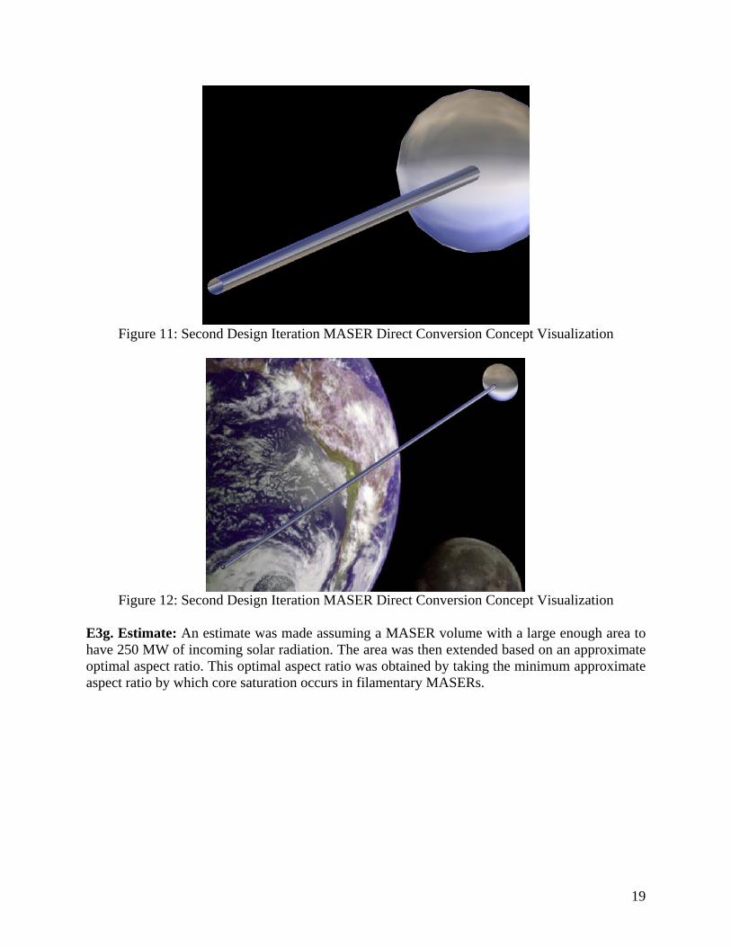
Figure 11: Second Design Iteration MASER Direct Conversion Concept Visualization
Figure 12: Second Design Iteration MASER Direct Conversion Concept Visualization
E3g. Estimate: An estimate was made assuming a MASER volume with a large enough area to have 250 MW of incoming solar radiation. The area was then extended based on an approximate optimal aspect ratio. This optimal aspect ratio was obtained by taking the minimum approximate aspect ratio by which core saturation occurs in filamentary MASERs.
19

Figure 13: MASER Aspect Ratio Relationship
Reference: [17] This volume was filled with an average naturally occurring SiO number density. The radius was scaled down by a factor of ten, proportionally increasing the density of the prior volume. This is based on essentially an argument for energy balance, that the energy will be focused into a smaller volume with more molecules to excite. An estimate of mass for a parabolic reflector of the original area and the surface area of the new smaller MASER column volume was made based on an average value of solar sail type reflective material. This estimated payload was then multiplied by an average of 3.3 as per typical satellite structural and system mass data from Space Mission Analysis and Design [22]. It should be noted that for comparison purposes, previous estimates of standard photovoltaics and optical rectennae do not include this factor, and are simply comparing the properties of the array. However, in an effort to take into any account any necessary structure to support a reflector and tube made of solar sail material this factor was included.
20

ESTIMATE CALCULATIONS: Typical Number Density of SiO MASER 1E+10 particles/cm3
SiO Molecular Weight 44 gram/mol Avagadros Number 6.02E+23 particles/mol Molecular Density 7.31E-13 g/cm3
Optimal Aspect Ratio from Chart 35 L/R Average Solar Energy Density 1370 W/m2
Incoming Energy 2.5E+08 W Reflector Area 182481.8 m2
Reflector Radius 241.0098 m Tube Length 8435.345 m Volume of Gas 1.54E+09 m3
Volume of Gas 1.54E+15 cm3
Mass of Vapor 1124.694 g Mass of Vapor 1.124694 kg Average Solar Sail Reflector Density 7.33 g/m2
Reflector Mass 1337.591 kg Tube Radius 24.10098 m Tube Surface Area 1277372 m2
Tube Mass 9363.139 kg Total Weight (Including 3.3*Payload from SMAD) 35316.12 kg Output Power Assuming 50% Efficiency 125000 kW Specific Power 3.53946 kW/kg Standard Photovoltaic Specific Power 0.25 kW/kg Percent Improvement over Conventional PV 1415.784 %
Table 3: MASER Direct Conversion System Estimates
21

G. APPLICATIONS: G1. Space Solar Power Grid: Aside from “saving the world,” space solar power is a great idea that has been around for a fairly long time. It ultimately offers nearly free and unlimited energy. In response to skeptical comments as to a space based solar power grid, further explanation as to the benefits of a SSP grid versus ground based solar power system will be reiterated. Primarily the SSP system gets 24 hours/day sunlight versus a maximum of 8, resulting in an initial factor of three. Additionally, there is atmospheric effects as shown in figure 10 that drastically reduce the solar energy density at the ground. Ground based solar power is also affected by seasons, weather, and land availability. Functional SSP would be a tremendous breakthrough. The main issue faced by such a project is the state of current technology. Specifically, launch costs, solar cell efficiency, and an infrastructure that would be receptive to such a grid. Based off the estimates listed in table 3, the benefit of alternative SSP technologies is evident. Cost savings of this magnitude transforms any SSP concept into feasibility. Additionally these revolutionary systems were designed around 100 GHz which would significantly reduce ground based infrastructure and therefore cost by limiting beam spreading. Compared to a commonly cited 2.4 GHz system the ground “foot print” of the beam should be nominally 2.4% as large. Comparison of a 125 MW Output SSP Satellite
Specific Power (kW/kg)
Mass (kg) Cost Using Atlas V at 6239.4 $/kg - ($)
Percent Cost of Conventional PV (%)
Conventional Photovoltaics 0.25 500000 3119700000 100Optical Rectenna 4.658 26835.55174 167437741.5 5.367110348MASER 3.539 35320.71207 220380050.9 7.064142413
Table 4: SSP Technology Estimate Comparison
These savings combined with an evolutionary path to SSP in order to solve the chicken and the egg issue of developing such a system would be a powerful proposal. Recently Prof. Narayanan Komerath detailed an evolutionary path in papers entitled “An Evolutionary Path for Space Solar Power” presented at the 2006 STAIF and ASCE conferences [23,24,25]. The evolutionary path was to develop a space based power transmission system, which would pay for itself from the savings from transmission costs. Further, such a system would enable green energy sources such as wind and solar plants to become base load sources and exchange power anywhere across the world. [23,24,25] G2. Electric Propulsion: Over the years a multitude of electric propulsion systems have been proposed and developed. The major drawback of these systems is a high mass per unit thrust, due to the power source and transmission system. One of the most commonly known forms of electric propulsion, ion engines, work by ionizing propellant particles by EM radiation such as xenon gas and accelerating them through an electric field. Magnetoplasma engines are a newer concept but work on somewhat similar priciples: heating neutral hydrogen gas into plasma using electric fields and contained by magnetic fields, the plasma then passes through an RF booster to further ionize the hydrogen plasma [16]. The University of Washington has also been looking into various other electric plasma based propulsion methods.
22

These propulsion systems could all be revolutionized by the massive amounts of energy available from the sun that could be harnessed by direct conversion systems. Energy could also be beamed from a solar power grid. This would eliminate one of the important opposition points to electric propulsion; that electric propulsion must often utilize massive on board power systems such as nuclear power generation in order keep power over the long range in which electric propulsion becomes effective. Direct conversion options eliminate the need for an onboard power system, which would both decrease the launch cost and increase the effectiveness of the propulsion system. Furthermore, direct frequency conversion is especially applicable because of the need for EM radiation to ionize particles. Mass and efficiency could be saved by directly converting to the needed radiation frequency. These mass savings are extremely important because of the low thrust nature of electric propulsion systems. As specified by the designs the direct conversion systems all either utilize a solar sail reflector or a thin film array. In the case of the thin film array, perhaps with future advances in fabrication technology, direct conversion technology might be combined with a solar sail. Landis suggests a hybrid electric propulsion and solar sail system [17]. In addition to direct conversion applying to the electric propulsion system, it would help as a sail by providing initial thrust and the magnitude of thrust needed for a mission.
23

H. CONCLUSION: The project goal, concepts developed, critical enabling technologies, and applications are detailed in table 5:
Table 5: Direct Conversion for SSP Summary
Direct Conversion for SSP Summary: Goal: Convert broadband solar radiation directly to lower narrowband frequency Concepts:
1. Optical Rectenna System: Solar radiation is coupled to thin film nanofabricated antenna array including either rectification components or THz sampling for wave reconstruction
a. Efficiency: 85-100% b. Specific Power Estimate: 4.658 kW/kg
2. Shocked Photonic Crystal System: Solar radiation gathered by solar sail-like parabolic reflector is focused through tailored dielectrically modulated shocked photonic crystal which simultaneously narrows the band and downshifts the frequency
3. Solar Pumped MASER System: Solar radiation gathered by solar sail-like parabolic reflector is focused through a low density molecular vapor contained in cylindrical resonator tube constructed from solar sail material producing a non-linear emission
a. Efficiency: > 50% b. Specific Power Estimate: 3.539 kW/kg
Critical Technologies:
1. Nanofabrication: sub 100 nm resolution 2. Control System: utilizes incoming power to stabilize SSP systems in orbit 3. Ultra Thin Solar Sail Fabrication 4. Terahertz Sampling: > 3000 THz
Applications:
1. Space Solar Power Grid 2. Electric Propulsion
To reiterate, direct conversion offers the potential to realize SSP as a feasible aerospace concept. The ability to convert broadband sunlight directly to a useable narrowband application dependent frequency reduces system mass and complexity while increasing efficiency and specific power. Out of the diverse array of possible technologies and options studied, a handful of concepts have shown potential to warrant further study. They have the potential to be enabling technologies in their own right for SSP systems and be a true paradigm shift for SSP.
24

I. BIBLIOGRAPHY: [1] Brown, W.C., “The History of Power Transmission By Radio Waves”. IEEE Trans.Vol. MTT-32, p:1230 (1984). [2] Brown, W.C., “Performance characteristics of the thin-film, etched-circuit rectenna”. IEEE MTT-S International Microwave Symposium Digest, p: 365- 367 (1984). [3] Berland, B., “PhotoVoltaic Technologies Beyond the Horizon: Optical Rectenna Solar Cell”. Final Report, NREL/SR-520-33263, February 2003. [4] U.S. Department of Energy, “Bandgap Energies of Semiconductors and Light”. Feb 2004. http://www.eere.energy.gov/solar/bandgap_energies.html[5] Murphy, D. M., Ekanazi, M.I., White, S.F., Spence, B.R., “Thin-Film and Crystalline Solar Cell Array System Performance Comparisons”. AEC-Able (ABLE) Engineering. [6] Tuttle, J.R., Szalaj A., Keane J., “A 15.2% AM0 / 1433 W/KG THIN-FILM CU(IN,GA)SE2 SOLAR CELL FOR SPACE APPLICATIONS”. 28th IEEE Photovoltaics Specialists Conference, Anchorage, AK September 15-22, 2000 [7] Kellum, M., Laubscher, B., “Solar Power Satellite Systems With a Space Elevator”. LAUR-04-4073. 3rd Annual International Space Elevator Conference, Washington, D.C., 29 June2004. [8] National Center for Photovoltaics. “Photovoltaics New Energy for the New Millenium”. www.nrel.gov/ncpv. [9] Robel, Michael K. “The cost of medium lift”. The Space Review. June 1, 2004. http://www.thespacereview.com/article/150/1[10] Ren, A., Kuo, S.P., “Frequency Downshift in Rapidly Ionizing Media”. 1994. [11] Iltchenko, V., Matsko, A., Savchenkov, A., Maleki, L., “A Resonator for Low-Threshold Frequency Conversion”. JPL. http://www.nasatech.com/Briefs/Dec04/NPO30638.html[12] Joannopoulos, John D., Reed, E., Soljacic, M., “Color of Shock Waves in Photonic Crystals”. Physical Review Letters. 23 May 2003. [13] Joannopoulos, John D., Reed, E., Soljacic, M., “Reversed Doppler Effect in Photonic Crystals”. Physical Review Letters. Sept 2003. [14] Joannopoulos, John D., Johnson, Steven G., “Photonic Cystals: The Road from Theory to Practice.” Massachusetts Institute of Technology. 2002. [15] “Solar Sail Technology Development: Mission Senarios” JPL. Mar 2002. http://solarsails.jpl.nasa.gov/introduction/mission-scenarios.html[16] M. Reid, J. Moran, “MASERs”. Annual Review of Astronomy and Astrophysics 1981. [17] Elitzur, M. “Astronomical MASERs”. Kluwer Academic Publishers. 1992. [18] Kiss, Z. J., Lewis, H. R., Duncan, R. C. Jr., “Sun Pumped Continuous Optical MASER”. Applied Physics Letters. March 1963. [19] Saiki, T., Uchida, S., Motokoshi, S., Imasaki, K., Nakatsuka, M., Nagayama, H., Saito, Y., Niino, M., Mori, M., “Development of Solar-Pumped LASERs for Space Solar Power Station”. Space Technology Applications International Forum. October 2005. [20] DARPA Efficient Mid-wave Infrared LASERs (EMIL) BAA06-20. http://www.fbo.gov/spg/ODA/DARPA/CMO/BAA06%2D20/Attachments.html[21] ARO (Arizona Radiowave Observatory) Website: “What is Submillimeter Astronomy?” http://kp12m.as.arizona.edu/docs/what_is_submillimeter.htm Accessed 5/1/2006. [22] Wiley L.J., Wertz J.R., “Space Mission Analysis and Design, 3rd Edition” Microcosm Press; 3rd edition (October 1999)
25

[23] Boechler, N., Hameer, S., Wanis, S., Komerath, N., “An Evolutionary Model for Space Solar Power”. STAIF 2006. [24] Boechler, N., Hameer, S., Wanis, S., Komerath, N., “An Evolutionary Model for Space Solar Power”. ASCE 2006. [25] Komerath, N., Wanis S., “The Kyoto Space Power Grid: Phase 1” 14 Feb. 2005 [26] NASA's Human Exploration and Development of Space Enterprise, “Propulsion Systems of the Future”. 15 May 2003. http://www.nasa.gov/vision/space/travelinginspace/future_propulsion.html[27] Winglee, R., “Magnetized Beamed Plasma Propulsion (MagBeam).” NIAC. March 2005. [28] Landis, Geoffrey A., “Optics and Materials Considerations for a LASER-propelled Lightsail”. Paper IAA-89-664 at the 40th International Astronautical Federation Congress, Málaga, Spain, Oct. 7-12, 1989. Revised December, 1989.
26