digtal simulation of mli based dynamic voltage restorer ... · pdf filea detailed analysis on...
TRANSCRIPT
ABSTRACT:
The Dynamic voltage restorer [DVR], a custom power device has been used to protect sensitive loads from the effect of voltage sags /swells on the distribution feeder. The DVR’s main function is to inject the difference in voltage to the power line and thus maintain the load side voltage at the optimum value. This paper presents the modeling aspects of the DVR system with the MLI working against voltage sags/swells by simulation. The digital simulation is carried out using MATLAB/SIMULINK. dc/dc converter is used to adjust the DC link voltage considering the amount of voltage sag so that the maximum possible output voltage levels are generated for a wide range of voltage sags.
Keywords- Powerquality, Dynamic voltage Restorer[DVR],Multilevel Inverter[MLI],Pulse width modulation[PWM],Total harmonic distortion[THD].
I. INTRODUCTION
A common characteristic of most electronics is that they are sensitive to voltage variations. Computers and other sensitive loads can lower their performance or even shutdown the process they are in control due to those variations. Voltage variations can be classified as disturbances that produce voltages below the nominal value, which are called voltage sags, and disturbances that produce voltages above the nominal value, which are called voltage swells.
Voltage sag is defined as a sudden reduction of supply voltage down 90% to 10% of nominal, followed by a recovery after a short period of time. Atypical duration of sag is 10ms to 1 minute. Voltage sag can cause loss of production in automated processes since voltage sag can trip a motor or cause its controller to malfunction. Voltage swell is defined as sudden increasing of supply voltage up 110% to180% in RMS voltage at the fundamental frequency with duration from 10ms to 1 minute. Switching off a large inductive load or energizing a large capacitor bank is atypical system event that causes swells. During
power disturbances Dynamic Voltage Restorer (DVR) installed in front of a critical load will appropriately provide correction to that load only. Also DVR cannot provide compensation during full power interruptions. Voltage sag is a momentary decrease in RMS voltage lasting between half a cycle to a few seconds. It is generally caused by faults in the power system and is characterized by its magnitude and duration. Voltage sag magnitude is defined as the net RMS voltage during voltage sag, which is usually in per unit of the nominal voltage level. The voltage sag magnitude depends on various factors like the type of fault, the location of the fault and the fault impedance.
Voltage sag/swell is most important power quality problems challenging the utility industry can be compensated and power is injected into the distribution system. By injecting voltage with a phase advance with respect to the sustained source-side voltage, reactive power can be utilized to help voltage restoration [1]. Dynamic Voltage Restorer, which consists of a set of series and shunt converters connected back-to-back, three series transformers, and a dc capacitor installed on the common dc link [3]. The Pulse-width modulation of Z-source inverter has recently been proposed as an alternative power conversion concept as they have both voltage buck and boost capabilities [4].The Z-source converter employs a unique X-shaped impedance network on its dc side for achieving both voltage-buck and boost capabilities this unique features that cannot be obtained in the traditional voltage-source and current-source converters. The proposed system is able to compensate long and significantly large voltage sags [2], [5] and [9].
Passivity-based dynamical feedback controllers can be derived for the indirect stabilization of the average output voltage. The derived controllers are based on a suitable stabilizing “damping injection” scheme [7]. Transformerless self-charging dynamic voltage restorer series compensation device used to mitigate voltage sags.
A detailed analysis on the control of the restorer for voltage sag mitigation and dc-link voltage regulation are presented [8]. Installation of the world's first Dynamic
DIGTAL SIMULATION OF MLI BASED DYNAMIC VOLTAGE RESTORER FOR VOLTAGE SAG
COMPENSATION SMITHA SETHUMADHAVAN1, Dr.P.USHARANI2
1 ME.scholar. Department of Electrical Engineering, RMK Engineering College, Kavaraipettai
2 Professor, Department of Electrical Engineering, RMK Engineering College, Kavaraipettai
International Journal of Scientific & Engineering Research, Volume 5, Issue 6, June-2014 ISSN 2229-5518
30
IJSER © 2014 http://www.ijser.org
IJSER

Voltage Restorer (DVR) on a major use. Utility system to protect a critical customer plant load from power system voltage disturbances. The installed system at an automated yarn manufacturing and weaving factory provides protection from disturbances [10].
The modeling and simulation of ZSI based DVR is presented [11]and [13]. The modeling and simulation of IDVR is presented [12]and [15]. Simulation of MLI based DVR is presented in [16].In this paper the modeling and implementation of Multilevel inverter based dynamic voltage restorer for voltage sag compensation is presented. The simulation results are presented to show the effectiveness of the proposed control method.
II. DYNAMIC VOLTAGE RESTORER
The control strategy is designed using the in-phase compensation technique. Voltage sag is detected as a sudden change in the magnitude of the load voltage.
Fig.1. Basic Operation of DVR
Dynamic voltage restorer was originally proposed to compensate for voltage disturbances on distribution systems. A typical DVR scheme is shown in Fig. 1. The restoration is based on injecting AC voltages in series with the incoming three-phase network, the purpose of which is to improve voltage quality by adjustment in voltage magnitude, wave-shape, and phase shift. These are important voltage attributes as they can affect the performance of the load equipment. Voltage restoration involves energy injection into the distribution systems and this determines the capacity of the energy storage device required in the restoration scheme
Fig. 2 shows the proposed DVR. It consists of an energy storage, a dc/dc converter, a multilevel inverter and the injection transformers. The capacitor C is used as a filter. The main aim in the proposed topology is to adjust the dc link voltage according to the amount of voltage sag. The dc output voltage of the energy storage(Vin ) is given to a dc/dc converter as its input voltage. The dc/dc converter offers a variable dc link voltage (Vdc) so that it can be adjusted considering the amount of voltage sag. A new method for application of a multilevel inverter in the
DVR structure is proposed in this paper. The proposed method relies on the adjusting the dc voltage input of the multilevel inverter using a dc/dc converter according to the voltage sag. As a result, for a wide range of voltage sag, the proposed DVR generates all of the possible voltage levels which is not possible in the existing methodologies. Cascaded seven level inverter is used.
Fig. 2 Block Diagram of MLI based DVR
III. VOLTAGE SAG COMPENSATION IN DYNAMIC VOLTAGE RESTORER
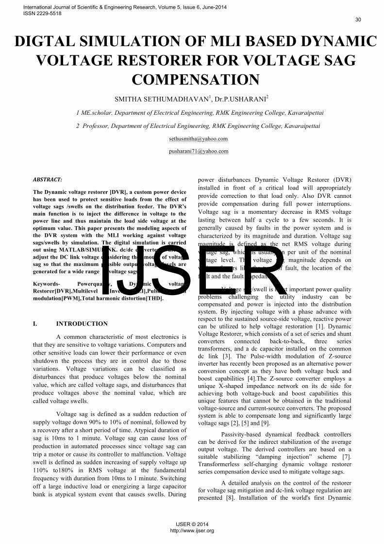
The simulation circuit of MLI based DVR is shown in Fig.3. The subsystem 4 consists of boost converter and multilevel inverter pulse generator which is shown in Fig.4.Initially the system was subjected to voltage sag at t=400ms and remains up to t=700ms with the total voltage sag duration of 300ms, in a run time of 1000ms. The cascaded seven level MLI switching pulses and FFT analysis of MLI output voltage is shown in Fig.5&7. The response of MLI based DVR for voltage sag compensation is shown in Fig.6. Uncompensated voltage, an injected voltage (seven level cascaded MLI) and the compensated voltages are shown in Fig.6.
International Journal of Scientific & Engineering Research, Volume 5, Issue 6, June-2014 ISSN 2229-5518
31
IJSER © 2014 http://www.ijser.org
IJSER
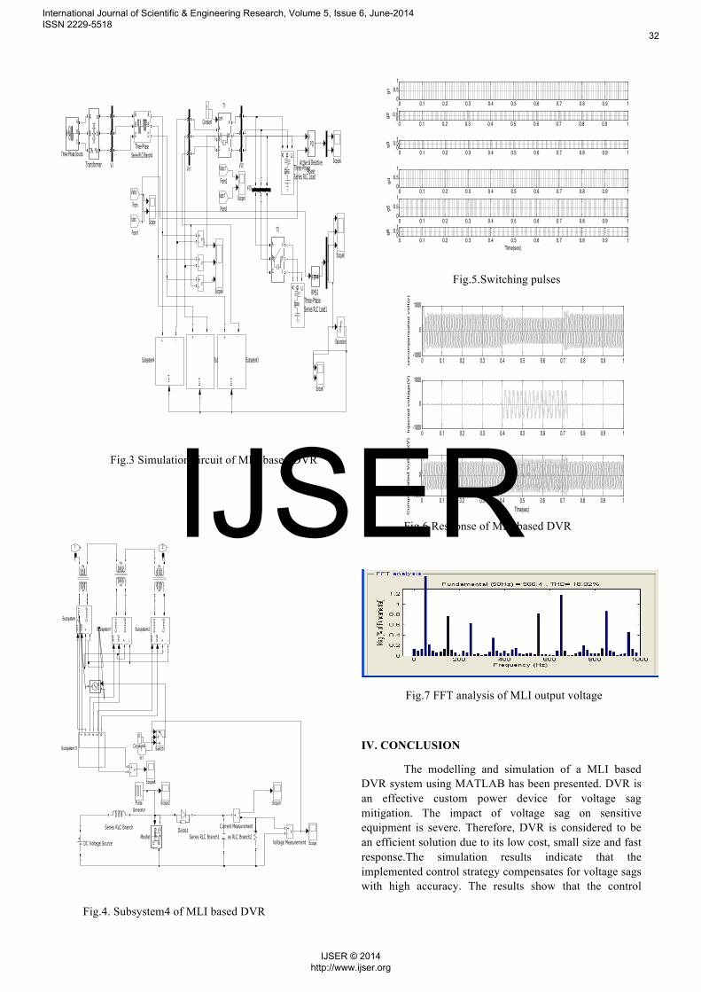
Fig.3 Simulation circuit of MLI based DVR
Fig.4. Subsystem4 of MLI based DVR
Fig.5.Switching pulses
Fig.6 Response of MLI based DVR
Fig.7 FFT analysis of MLI output voltage
IV. CONCLUSION
The modelling and simulation of a MLI based DVR system using MATLAB has been presented. DVR is an effective custom power device for voltage sag mitigation. The impact of voltage sag on sensitive equipment is severe. Therefore, DVR is considered to be an efficient solution due to its low cost, small size and fast response.The simulation results indicate that the implemented control strategy compensates for voltage sags with high accuracy. The results show that the control
v+-
v+-
v+-
A B C
a b cV-I3
A
B
C
a
b
c
V-I2
A
B
C
a
b
c
V-I1
A
B
C
a
b
c
V-I
A
B
C
a
b
c
Transformer
ABC
Three-Phase Source
A B CThree-PhaseSeries RLC Load1
A B C
Three-PhaseSeries RLC Load
ABC
ABCThree-Phase
Series RLC Branch4
A
B
C
a
b
c
T2
comABC
a
b
c
T1
In
1
+ -
Subsystem7
In
1
+ -
Subsystem4
In
1
+ -
Subsystem3
Scope7
Scope6
Scope5
Scope4
Scope1
Scope
Saturation
signalrms
RMS1
Iabc1
From3
Vabc1
From2
Iabc
From1
Vabc
From
1
Constant
V
IPQ
Active & ReactivePower
2 -1 +
v+-
v+-
Voltage Measurement
Switch1
In1
In2
+ -
Conn1
Conn2
Subsystem2
1 2 3 4 5 6
Subsystem11
In1
In2
+ -
Conn1
Conn2
Subsystem1In1
In2
+ -
Conn1
Conn2
Subsystem
Series RLC Branch2Series RLC Branch1Series RLC Branch
Scope8
Scope2 Scope1
Scope
PulseGenerator
gm
DS
Mosfet
12
12
12
Diode1
DC Voltage Source
i+ -Current Measurement
s-+
0
Constant51In1
0 0.1 0.2 0.3 0.4 0.5 0.6 0.7 0.8 0.9 10
0.51
g1
0 0.1 0.2 0.3 0.4 0.5 0.6 0.7 0.8 0.9 10
0.51
g2
0 0.1 0.2 0.3 0.4 0.5 0.6 0.7 0.8 0.9 10
0.51g3
0 0.1 0.2 0.3 0.4 0.5 0.6 0.7 0.8 0.9 10
0.51
g4
0 0.1 0.2 0.3 0.4 0.5 0.6 0.7 0.8 0.9 10
0.51
g5
0 0.1 0.2 0.3 0.4 0.5 0.6 0.7 0.8 0.9 10
0.51
Time(sec)
g6
0 0.1 0.2 0.3 0.4 0.5 0.6 0.7 0.8 0.9 1-1000
0
1000
uncom
pensate
d v
olt(v
)
0 0.1 0.2 0.3 0.4 0.5 0.6 0.7 0.8 0.9 1-1000
0
1000
Inje
cte
d v
oltage(V
)
0 0.1 0.2 0.3 0.4 0.5 0.6 0.7 0.8 0.9 1-1000
0
1000
Time(sec)
Com
pensate
d V
oltage(V
)
International Journal of Scientific & Engineering Research, Volume 5, Issue 6, June-2014 ISSN 2229-5518
32
IJSER © 2014 http://www.ijser.org
IJSER

technique is simple and efficient method for voltage sag compensation.
REFERENCES
[1] Choi S. S, Li B. H, and Vilathgamuwa D. M (2000) “Dynamic voltage restoration with minimum energy injection,” IEEE Trans. Power Systems, vol. 15, pp. 51-57.
[2] Gajanayake C. J, Vilathgamuwa D. M, and Loh P. C (2005) “Small-signal and signal-flow-graph modeling of switched Z-source impedance network,” IEEE Power Electronics Letters, vol. 3, pp. 111-116.
[3] Jimichi T, Fujita H., and Akagi H. (2005) “Design and experimentation of a dynamic voltage restorer capable of significantly reducing an energystorage element,” in Conf. Record Industry Applications Conference,14th IAS Annual Meeting..
[4] Loh P. C, Vilathgamuwa D. M, Lai Y. S, Chua G. T, and Li Y (2004) “Pulse-width modulation of Z-source inverters,” in Conf. Record IEEE Industry Applications Conference, 39th IAS Annual Meeting.
[5] Peng F. Z. (2003) “Z-source inverter,” IEEE Trans. Industry Applications, vol.39, pp. 504-510.
[6] Samra N. A, Neft C, Sundaram A, and Malcolm W (1995) “The distribution system dynamic voltage restorer and its applications at industrial facilities with sensitive loads,” in Proc. Power Conversion Intell. Motion Power Quality Long Beach, CA.
[7] Sira-Ramirez H and Ortega R (1995) “Passivity-based controllers for the stabilization of DC-to-DC power converters,” in Proc. 34th IEEE Conference on Decision and Control.
[8] Sng E. K. K, Choi S. S, and Vilathgamuwa D. M (2004) “Analysis of series compensation and DC-link voltage controls of a transformerless selfcharging dynamic voltage restorer,” IEEE Trans. Power Delivery, vol.19, pp. 1511-1518.
[9] Torabzad S, Babaei E, Kalantari M (2010) “Z-Source Inverter based Dynamic Voltage Restorer” 1st Power Electronic & Drive Systems & Technologies Conference.
[10] Woodley N. H, Morgan L, and Sundaram A (1999) “Experience with an inverter-based dynamic voltage restorer,” IEEE Trans. Power Delivery, vol. 14, pp. 1181-1186.
[11] Usha Rani P. and Rama Reddy S. (2011), ‘Digital Simulation of an Interline Dynamic Voltage Restorer for Voltage Compensation’, International conference on Computer, Communication and Electrical Technology ICCCET 2011, 18th& 19th March 2011, National College of Engineering, pp. 133-139 ( IEEE Xplore 978-1-4244-9391-3/11)
[12] Usha Rani P. and Rama Reddy S. (2011), ‘Modeling and Simulation ZSI based DVR for voltage compensation’, International conference on Computer, Communication and Electrical Technology ICCCET 2011, 18th& 19th March 2011, National College of
Engineering, pp. 90-96 (IEEE Xplore 978-1-4244-9391-3/11)
[13] Usha Rani P. and Rama Reddy S. (2011), ‘Voltage sag / swell compensation in an interline dynamic voltage restorer’, International conference on Emerging Trends in Electrical and Computer Technology, ICETECT 2011, 23rd& 24th March 2011, St. Xaviers Catholic College of Engineering, pp. 309-314 (IEEE Xplore 978-1-4244-7925-2/11)
[14] Usha Rani P. and Rama Reddy S. (2011), ‘Voltage sag / swell compensation using Z-source inverter based dynamic voltage restorer’, International conference on Emerging Trends in Electrical and Computer Technology, ICETECT 2011, 23rd& 24th March 2011, St. Xaviers Catholic College of Engineering, pp. 268-273 (IEEE Xplore 978-1-4244-7925-2/11)
[15] Usha Rani P (2013), ‘Voltage Swell Compensation in an Interline Dynamic Voltage Restorer’, Journal of Scientific and Industrial Research, -Accepted for publication-JSIR-5101-Ref.MSS/Rev/JSIR-5101 21.06.2013
[16] Ebrahim Babaei and Mohammad Farhadi Kangarlu (2011)”A new scheme for MLI based DVR”, International Conference on Electrical machines and systemsICEMS,PP1-6
International Journal of Scientific & Engineering Research, Volume 5, Issue 6, June-2014 ISSN 2229-5518
33
IJSER © 2014 http://www.ijser.org
IJSER

International Journal of Scientific & Engineering Research, Volume 5, Issue 6, June-2014 ISSN 2229-5518
34
IJSER © 2014 http://www.ijser.org
IJSER