development of cooling and cleaning systems for enhanced
TRANSCRIPT

MultiCraft
International Journal of Engineering, Science and Technology
Vol. 8, No. 1, 2016, pp. 43-56
INTERNATIONAL JOURNAL OF
ENGINEERING, SCIENCE AND TECHNOLOGY
www.ijest-ng.com www.ajol.info/index.php/ijest
2016 MultiCraft Limited. All rights reserved
Development of cooling and cleaning systems for enhanced gas quality for 3.7 kW gasifier-engine integrated system
K. M. Nataraj1, N.R. Banapurmath2, G. Manavendra3, V.S. Yaliwal4
1Department of Mechanical Engineering, J.S.S. Academy of Technical Education, Bangalore,560 060 INDIA 2 Department of Mechanical Engineering, B.V.B. College of Engineering and Technology, Hubli 580 031, Karnataka, INDIA
3 Department of Mechanical Engineering, B.I.E.T. Davangere 577004, Karnataka, INDIA
4 Department of Mechanical Engineering, S.D.M. College of Engineering and Technology, Dharwad 580 002, Karnataka, INDIA E-mail: [email protected], Tel. No. : +91 9880726748
Abstract Energy from biomass based gasifier-engine integrated systems are becoming more popular for power generation applications in rural and urban driven societies. The quality of producer gas from the down draft gasifiers plays a significant role in power generation aspects. During gasification, tar is produced and its magnitude depends on the type of gasification process and biomass feedstock used which can vary from biomass to municipal solid waste (MSW) available. The pollutants generated from gasification include particulate matter, tars, and char and acid gases. A major challenge for commercializing the gasification process is to reduce tar. In order to address these tar related problems a cleaning and cooling system has been developed in house that facilitates tar removal to acceptable levels tolerated by the internal combustion (IC) engine and meets emission standards as well. The main objective of the present work is to reduce tar level and develop control strategies for improving the performance and emission of diesel engines. Results showed that the brake thermal efficiency of the dual fuel engine used was increased by 2-4% and tar was reduced from325 mg/Nm3 in the gasifier to 60-50 mg/Nm3entering the engine. In addition, the emission levels such as hydrocarbon, carbon monoxide were reduced comparatively with developed cooling-cleaning system provided in the conventional gasifier-engine system. The biomass consumption rate was40kg/h. Air and gas flow rates were measured to be 18.8 m3/h and 20.12 kg/h respectively. The temperature of the gas after developed cooling and cleaning system was found to be 34 °C. Keywords: Dual fuel engine, cooling-cleaning system, Rice bran oil methyl ester, tar, performance, emissions. DOI: http://dx.doi.org/10.4314/ijest.v8i1.4
1. Introduction Most of the Indian villagers depend on agriculture for their daily living. India is made up of about 6 lakh villages and is the 3rd largest in energy utilization. To full fill the needs of Indian energy need it is becoming difficult because of increasing population. This can be addressed suitably if some percent of energy is produced through renewable energy sources like biodiesel and biomass derived gaseous fuel (Banapurmath et al., 2008; Banapurmath et al., 2009; Basavarajappa et al., 2015). This seems to be more appropriate, because India has a huge potential for biomass and agricultural residues. Also even if India could utilize complete waste land, it will be able to fulfil the demand to some extent. As conventional biomass utilization processes are crude and highly inefficient, and have the capability of substituting conventional energy sources with renewable energy sources used in hybrid mode energy generation for future requirements. Open air burning of biomass results in inefficient energy utilization, liberation and process environmental hazards. Therefore, a feasible solution for technical application of biomass energy is use of biomass through a gasification process. Gasification technology and development is on the rising side of the knowledge curve, thus in future; gasification systems may turn out to be more attractive even at higher capacity levels for safe power application. Thus, the technologies are being promoted by the Ministry for Conversion of Biomass to electricity via biomass gasification.

Nataraj et al. / International Journal of Engineering, Science and Technology, Vol. 8, No. 1, 2016, pp. 43-56 44
Although biomass is getting increased attention as renewable energy source, one of the existing problems still to be addressed is the reduction of the high level of tar present in the product gas from gasification of biomass. Biomass gasification is the process by which solid biomass materials are converted using a series of thermochemical reactions, to a combustible gas called producer gas. Slower combustion in a gasifier and slow heating rate due to low temperature results in the formation of high molecular weight hydrocarbons called as tar. The conversion of biomass to product gas results in tar and corresponds to as much as one third of mass feed. The combustible gas comprises mainly of carbon monoxide (18-22%); hydrogen (15-20%); methane (1-5%); carbon dioxide (8-12%) and nitrogen (45-55%). The calorific value of producer gas is 4.2 – 5.0 kJ/m3.Gasification with good quality gas in terms of energy and lowtar content in the gas is the main research in gasification process as far as gas is required for engine applications. Tar content in the product gas depends on the operating parameters of gasifier, fuel type, oxidizing agent and gasifier type. The producer gas leaving gasifier has temperature of about 300-400 0C for wood gas and 400-500 0C for charcoal gas. Presence of tar in the gas results in corrosion of engine components and equipment. It gets mixed with soot and ashes tar traces and steam vapour, which causes wear and tear of engine components (Mandwe et al., 2006; Rathore et al., 2009; Patak et al., 2007; Singh et al., 2014). In addition this will lead to high hydrocarbon and carbon monoxide emissions if it is used for engine applications. Gas cleaning and waste handling in a gasifier-engine system is one of the challenges for the adoption of the technology at small-scale power generation. Parikh et al. (1989) have reported that the design and volume content of cooling-cleaning system is an important aspect of the gasifier-engine system design. In view of this, to eliminate the tar from the producer gas, it is essential to carry out cleaning over tar and dust particles from the product gas before its engine application. In this context, external heating of a tar containing gas (in a range of 900–1150 0C) results in polymerization of small tar components, which produces heavier hydrocarbons. This polymerization finally leads to the formation of soot. In practice, this soot can be removed by means of an appropriate filter. Therefore, this process can be used for gas cleaning (Houbenet al., 2002; Knoef, 2005; Brandt and Henriksen, 1996). The research work presented mainly finds application in power generation sector for rural population. Hence the present study was carried out with sole objective of developing a dry filter system for a single cylinder, four stroke, and water-cooled, direct injection diesel engine application having conventional cooling cleaning system and to conduct the performance test on the gasifier-engine system. Comparison of existing filter with the developed two stage (dry filter 1 and 2) has been presented and analyzed. 2. Development of cooling and cleaning system The use of dry sand filters after a wet filter has been reported by the Indian Institute of Science and is found to be ineffective and simple way of removing particulates and tar from the gas (Mukunda et al., 1994). The cooling and cleaning system was developed to improve the volumetric efficiency of engine and clean the product gas. Design and volume content of cooling–cleaning system is an important aspect of the gasifier-engine system design (Parikh et al., 1989). Good design of such systems with filters adopted significantly improves the performance of the engine. The tar laden gas causes erosion, corrosion and environmental problems in downstream equipment (Bridgewater, 1995). In the present work, two dry filters (1 and 2) were developed which filters the impurities and lowers the temperature of gas substantially. Initially, cleaning and cooling of producer gas leaving the gasifier was carried out by wet filter alone and then a combination of wet and two dry filters were developed as shown in Fig. 1. The cooled producer gas is then allowed to pass through a silica chamber in order to remove the moisture content of the gas. The two-stage filtering ensures that the gas is cleaned tothe desired level for use in the engine applications. Vapours of organic compounds in the gas filtered will be transferredtothe filter 1 and 2respectively.In the dry filter, water vapour or tar condenses from the gas stream. In the developed dry filters large 10 mm thick stainless steel were used and inside filter was mounted to prevent high tar and dust. The dry filter 1 was designed with an increased volume by 60% and dry filter 2 by 100% compared to engine swept volume which provides a larger contact area for the cleaned gas. Wet filter, newly developed dry filters of cooling and cleaning system are as shown in Figure 1(a), (b) and (c) , dimensions of the dry filter 1 and 2 as shown in table1 . Wet filter is made up of mild steel and has internal metallic mesh wound by non-woven textile fabric filter for removal of tar and gas particle with water content that is not removed by wet filter cooling system. Outlet from wet filter is connected to bottom of 1stdry Filter for inlet of gas and from top of 1st Filter for outlet of gas is connected to bottom of 2nddry Filter and from top of filter outlet of gas is intern connected to inlet of Venturimeter where measured quantity of producer gas is let into engine cylinder during the operation. Gas lines which is used in the cooling and cleaning system is made of 1 inch flexible heat resistant pipe.

Nataraj et al. / International Journal of Engineering, Science and Technology, Vol. 8, No. 1, 2016, pp. 43-56 45
(a) Wet filter
Fig (b) Dry Filter-1
Fig (c) Dry Filter-2
Fig. 1 Dry filters 1 and 2 and their details
Table1 Dimensions of Dry filters TYPE DIMENSIONS
Dry Filter (Hot gas cleaning)
Filter-1 ФD2=1250mm, H1=470mm, H2=490mm Filter-2 ФD3=1500mm, H3=470mm, H2=490mm

Nataraj et al. / International Journal of Engineering, Science and Technology, Vol. 8, No. 1, 2016, pp. 43-56 46
3. Characterization of coconut shell biomass derived producer gas
In the present study woody biomass from coconut shell was cut into suitable size and separated and dried. Coconut shell biomass for down draft gasifier and renewable liquid fuel derived from Rice bran oil called as Rice bran oil methyl ester (ROME) were used for the engine applications and their properties are listed in Table2. Table 3 gives the typical composition of producer gas derived from coconut shell biomass obtained from gasification on volumetric basis.
Table 2 Properties of Diesel, Rice bran Oil and Coconut shell biomass
Coconut shell Biomass Sl No
Properties Diesel Rice Bran oil
ROME Property Biomass
1 Viscosity @ 40 0 C (cst)
4.59 44.850 5.6 Moisture content (% w/w)
15.4
2 Flash point 0 C 56 270 163 Ash content (w/w) 0.99 3 Calorific Value in
kJ / kg 45000 35800 36,010 Volatile matter
(%w/w) 81
4 Specific gravity 0.830 0.915 0.870 Fixed carbon (%w/w) 14.8
5 Density Kg / m3 830 915 890 Sulphur (%w/w) 0.12 8 Type of oil ---- Non
edible Non edible
Nitrogen (% w/w) 0.29
Calorific value (cal/g) 3188
Density (kg/m3) 340
Table 3 Composition of producer gas from Coconut shell biomass from downstream of gasifier
Constituents Biomass
CO2, % H2, % CO, % N2, % CH4, % Water
vapor, % Calorific value,
kJ/Nm3 Coconut Shell biomass
8-14 14 19.0 -- 3 4 4800
4. Experimental setup The gasifier-engine system consists of a diesel engine, downdraft gasifier; gas cooler-cleaner set up, coupled to an eddy current dynamometer for loading arrangement and is shown in Figure 1. The specification of the engine and gasifier is given in Table 3. The engine was coupled to an eddy current dynamometer. The injector opening pressure and the static injection timing as specified by the engine manufacturer were 205 bar and 230 before top dead centre (bTDC), respectively. The producer gas was generated using downdraft gasifier. Gas flow was measured using a calibrated venturimeter provided with digital gas flow meter. The maximum compression ratio used is 17.5. The cooling of the engine was accomplished by the water circulating through the jackets of the engine block and cylinder head. The cylinder pressure was measured using piezoelectric transducer fitted to the cylinder head. In the present study, the amount of both the injected fuels (diesel and ROME) was measured on a volumetric basis. Liquid fuel injection was kept constant by adjusting the governor speed so that a constant speed is maintained in both the injected fuel combinations. Hartridge smoke meter and five-gas analyzer was used to measure exhaust gas during the steady-state operation. Throughout the experiments, the gas flow rate and the engine speed were kept constant. For the present experimental investigation on dual fuel engine, an injection timing of 270bTDC and injection pressures of 205 and 240 bar for diesel and ROME were maintained respectively. Finally, the results obtained with the ROME–producer gas operation were compared with diesel–producer gas operation. 4.1 Pressure Measurement In the experimental work, pressure drops were measured regularly across the gasifier, the gas clean-up systems (including wet and dry filters 1 and 2) and for air flow across orifice plate. The pressures within the gasifier will be close to atmospheric and generally will be measured in centimeters of water column. Pressure drops and differential pressures can be measured by a U-tube

Nataraj et al. / International Journal of Engineering, Science and Technology, Vol. 8, No. 1, 2016, pp. 43-56 47
manometer (0 – 100mm range) filled with colored liquid. For convenience and portability, they can be made from transparent glass tube and flexible pipes. Commercial units are available in a wide range of accuracies, from 0.25% - 3% of the full-scale reading. 4.2 Gas Flow Measurement Clean gas flow was measured using a venturimeter with digital manometer as shown in experimental set. The venturimeter provided gives a higher pressure signal with a minimum pressure drop, because the divergent downstream section of the meter conserves gas momentum by converting velocity back into pressure. The venturimeter is designed in such a way that the surfaces the impact offered by tars and particles are avoided and hence contaminant build up is minimal and the maintenance required for a permanent installation is reduced. 4.3 Temperature Measurements Thermocouples (such as Chromel-Alumel type K) have been used to measure various gasifier temperatures. Low temperatures are suitably measured with ordinary thermometers. Thermocouples have also been used along with automatic recording of the measurements done. Chromel-Alumel (type K) thermocouples can be used continuously to record higher temperatures and provide an almost linear electrical signal of 40 /lVrc. Sheath thermocouples with sheathing are used during experimentation with producer gas applications, because thermocouple alloys will react with various gas compositions. Thermocouples are best suited to most gasifier measurements.
Fig. 2: Experimental Test Rig
Nataraj et al. / International Journal of Engineering, Science and Technology, Vol. 8, No. 1, 2016, pp. 43-56 48
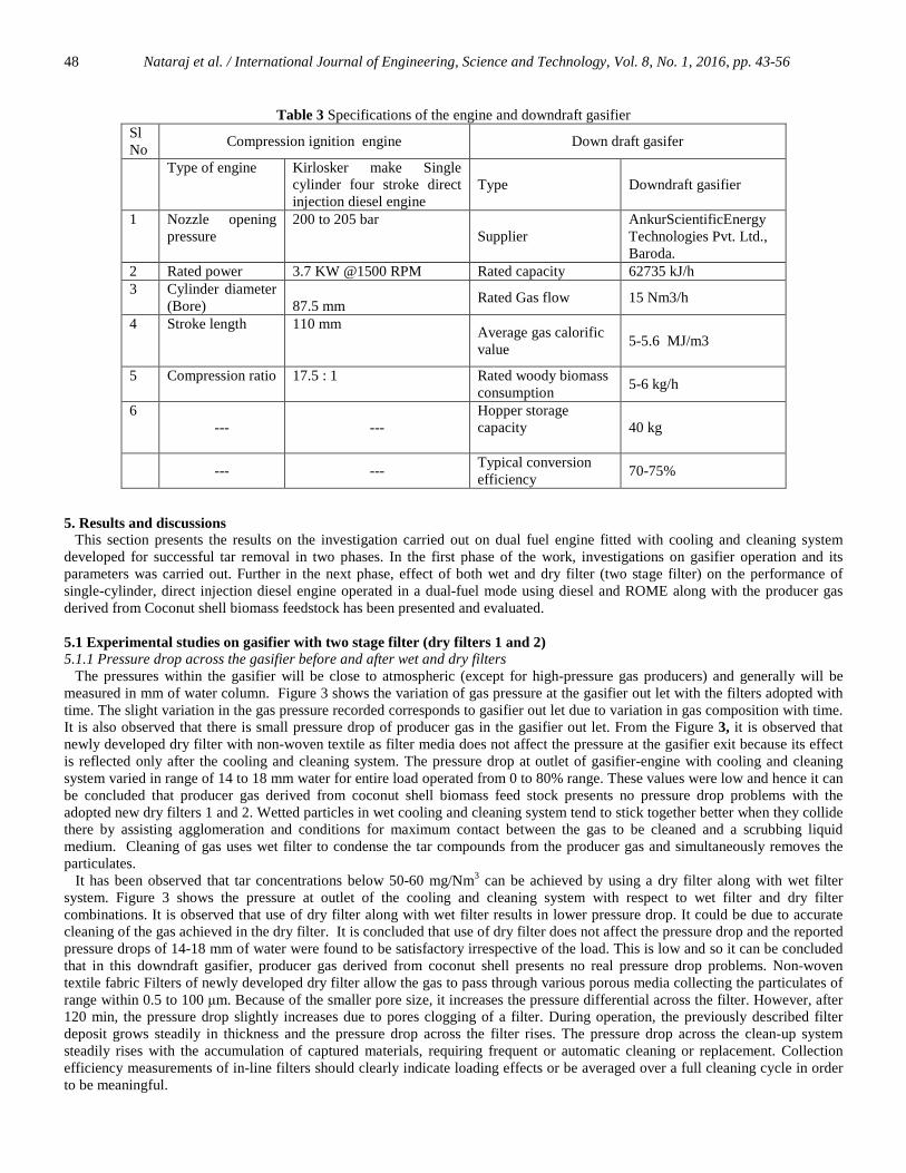
Table 3 Specifications of the engine and downdraft gasifier Sl No
Compression ignition engine Down draft gasifer
Type of engine Kirlosker make Single cylinder four stroke direct injection diesel engine
Type Downdraft gasifier
1 Nozzle opening pressure
200 to 205 bar Supplier
AnkurScientificEnergy Technologies Pvt. Ltd., Baroda.
2 Rated power 3.7 KW @1500 RPM Rated capacity 62735 kJ/h 3 Cylinder diameter
(Bore) 87.5 mm
Rated Gas flow 15 Nm3/h
4 Stroke length 110 mm Average gas calorific value
5-5.6 MJ/m3
5 Compression ratio 17.5 : 1 Rated woody biomass consumption
5-6 kg/h
6 --- ---
Hopper storage capacity
40 kg
--- ---
Typical conversion efficiency
70-75%
5. Results and discussions This section presents the results on the investigation carried out on dual fuel engine fitted with cooling and cleaning system developed for successful tar removal in two phases. In the first phase of the work, investigations on gasifier operation and its parameters was carried out. Further in the next phase, effect of both wet and dry filter (two stage filter) on the performance of single-cylinder, direct injection diesel engine operated in a dual-fuel mode using diesel and ROME along with the producer gas derived from Coconut shell biomass feedstock has been presented and evaluated. 5.1 Experimental studies on gasifier with two stage filter (dry filters 1 and 2) 5.1.1 Pressure drop across the gasifier before and after wet and dry filters The pressures within the gasifier will be close to atmospheric (except for high-pressure gas producers) and generally will be measured in mm of water column. Figure 3 shows the variation of gas pressure at the gasifier out let with the filters adopted with time. The slight variation in the gas pressure recorded corresponds to gasifier out let due to variation in gas composition with time. It is also observed that there is small pressure drop of producer gas in the gasifier out let. From the Figure 3, it is observed that newly developed dry filter with non-woven textile as filter media does not affect the pressure at the gasifier exit because its effect is reflected only after the cooling and cleaning system. The pressure drop at outlet of gasifier-engine with cooling and cleaning system varied in range of 14 to 18 mm water for entire load operated from 0 to 80% range. These values were low and hence it can be concluded that producer gas derived from coconut shell biomass feed stock presents no pressure drop problems with the adopted new dry filters 1 and 2. Wetted particles in wet cooling and cleaning system tend to stick together better when they collide there by assisting agglomeration and conditions for maximum contact between the gas to be cleaned and a scrubbing liquid medium. Cleaning of gas uses wet filter to condense the tar compounds from the producer gas and simultaneously removes the particulates. It has been observed that tar concentrations below 50-60 mg/Nm3 can be achieved by using a dry filter along with wet filter system. Figure 3 shows the pressure at outlet of the cooling and cleaning system with respect to wet filter and dry filter combinations. It is observed that use of dry filter along with wet filter results in lower pressure drop. It could be due to accurate cleaning of the gas achieved in the dry filter. It is concluded that use of dry filter does not affect the pressure drop and the reported pressure drops of 14-18 mm of water were found to be satisfactory irrespective of the load. This is low and so it can be concluded that in this downdraft gasifier, producer gas derived from coconut shell presents no real pressure drop problems. Non-woven textile fabric Filters of newly developed dry filter allow the gas to pass through various porous media collecting the particulates of range within 0.5 to 100 µm. Because of the smaller pore size, it increases the pressure differential across the filter. However, after 120 min, the pressure drop slightly increases due to pores clogging of a filter. During operation, the previously described filter deposit grows steadily in thickness and the pressure drop across the filter rises. The pressure drop across the clean-up system steadily rises with the accumulation of captured materials, requiring frequent or automatic cleaning or replacement. Collection efficiency measurements of in-line filters should clearly indicate loading effects or be averaged over a full cleaning cycle in order to be meaningful.

Nataraj et al. / International Journal of Engineering, Science and Technology, Vol. 8, No. 1, 2016, pp. 43-56 49
Fig. 3 Variation of pressure drop with time
5.1.2 Temperature of the gas before and after the dry filter:
Variation of temperature of gas with respect to time for both wet and dry filter combinations is shown in Figure 4. It can be observed from the figures that the gas temperature increases with increasing in time. This is because increased air fuel ratio increases the amount of oxygen input and thus there is increase in degree of oxidation of volatiles. These volatiles in return convert more chemical energy into sensible heat energy and results in higher temperature. It is mandatory that that temperature of around 30 - 40 0C is favorable for I.C. engine applications. Thus higher temperature more than 40 0C does not seem to be favorable for engine applications. On an average the temperature of gas leaving the gasifier is found to be 350 to 400oC. If the temperature is more than 400oC, is an indication that partial combustion of gas is taking place. This generally happens when the air flow rate through the gasifier is higher than the designed value. Coconut shell has acceptable temperature range due to acceptable volatile matter in it. However, ash presence in the coconut shell leads to some operational problems. After 120 min of gasifier operation the temperature of gas becomes low because of formation of clinker due to ash fusion in reduction zone, with uneven size of fuel and temperature increases gradually because of lower volatile matter available in biomass feed stock. Results showed that use of non-woven textile as fabric dry filters lowers the gas temperature due more residence time in the dry filter. This will indeed facilitate gas directly to the engine inlet.
Fig. 4 Variation of temperature with time
5.1.3 Superficial velocity:
Variation of superficial velocity with time is shown in Figure 5. Superficial velocity (SV) within range of 0.01 to 0.4 m/s were reported associated with low gravimetric tar (Yamazaki et al.,) and SV more than 2.5 m/s creates negative effect of reducing the tar conversion by shortening the residence time and more char fragments from bed conversion into high particle yield which in turn increases work load on cooling and cleaning system. SV within range of 0.01 to 0.18 m/s, further provides filtration and

Nataraj et al. / International Journal of Engineering, Science and Technology, Vol. 8, No. 1, 2016, pp. 43-56 50
cooling of producer gas in cooling and cleaning system makes the gas composition suitable for I.C. engine Operation. Figure 6 shows the flow rate of producer gas through both wet and dry filter systems and it is observed that the dry filters 1 and 2 reduce the gas flow rate when compared to wet filter and hence ensures a SV of acceptable norms.
Figure 5: Variation of Superficial velocity with time
Fig. 6 Variation of flow rate with time
5.2 Performance evaluation of the gasifier-engine system:
In the second phase of the work, effect of two stage filter on the performance of diesel engine operating on dual fuel mode has been presented and evaluated. During experimental investigation, the dual fuel mode is operated with manufacturer setting with wet filter (injection timing: 230bTDC, injection pressure: 205 bar, compression ratio: 17.5) and optimized engine setting (injection timing: 270bTDC, injection pressure: 230 bar, compression ratio: 17.5) with wet and dry filter 1. Further, the work was extended to study the effect of adding second dry filter 2 along filter 1 and existing wet filter. The engine was operated at constant speed of 1500 rpm and operated with nozzle having 4 hole each orifice of 0.2 mm diameter and carburetor (45o). Finally, the effect of developed dry filter on the performance of dual fuel engine was compared and analyzed in the following section.
5.2.1 Performance characteristics:

Nataraj et al. / International Journal of Engineering, Science and Technology, Vol. 8, No. 1, 2016, pp. 43-56 51
Effect of dual fuel operation on the brake thermal efficiency (BTE) at all loads is presented in Figure 7. The BTE of the dual-fuel engine operated using diesel–producer gas with wet filter, and along with dry filter 1 and 2 at 80% load were found to be 16.34, 17.12% and 18.9% respectively. From the results, higher BTE was observed for diesel–producer gas operation compared to ROME-producer gas operation in both versions of wet filter and dry filter 1 and 2 respectively. For ROME and PG combination being same incomplete combustion caused by the high molecular weight hydrocarbons (tar), lower air/fuel equivalence ratio in wet filter system shows lowered performance when compared to that using wet and dry filter (1 and 2) combinations.
Further increased ignition delay of ROME operation along with lower flame temperature and flame velocity of producer gas is responsible for the observed trends. In addition, for the same fuel combination, dual fuel operation with both wet and dry filters 1and 2 resulted in improved BTE. This could be due to improved quality of producer gas, volumetric efficiency and air-producer gas mixing available. The equivalence ratios for diesel-producer gas with existing filter, ROME–producer gas operation with wet filter, and dry filter 1 and 2 were found to be 0.66, 0.54, 0.56 and 0.60respectively at 80% load. It clearly indicates that there is insufficient air for the complete combustion of the ROME–producer gas combination when wet filter alone was used.
Fig. 7 Variation of brake thermal efficiency with brake power
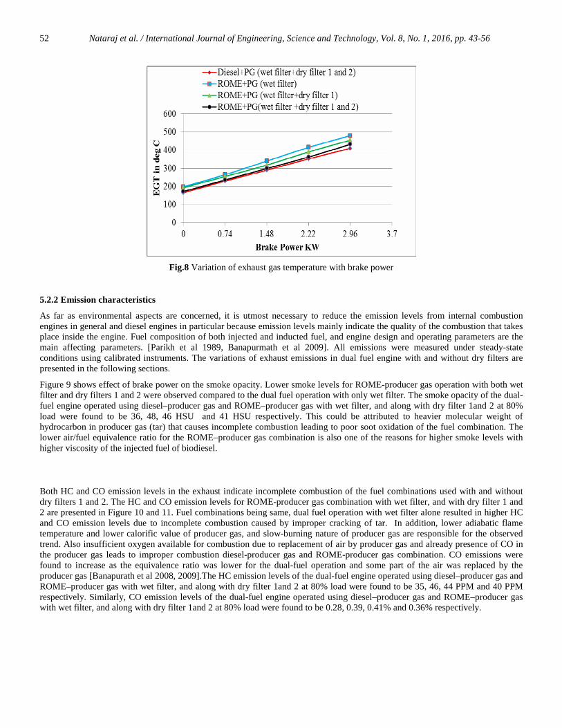
Figure 8 shows the variation of exhaust gas temperature (EGT) with brake power. ROME– producer gas dual fuel engine operation with wet filter results in to higher EGT compared to that operation with both wet, dry filters 1and 2 combinations used. EGT depends on the quality of producer gas, amount of producer gas inducted into the engine cylinder, nature of combustion and how much producer gas was taking part in the combustion. Higher EGT was observed with wet filter due to incomplete combustion caused by the combustion of ROME along with slow burning producer gas. This could also be attributed to burning of fuel combination in diffusion combustion phase rather than premixed combustion phase [Banapurmath et al., 2008]. For the same fuel combination of ROME-producer gas, wet filter with dry filter 1 and 2 resulted in lower EGT compared to the dual fuel engine with only wet filter operation and could be attributed to the fact that less heat energy was utilized for better combustion caused by the presence of tar. In addition, decreased flame velocity during rapid combustion phase leading to slow burning of the fuels used is also responsible for these observed trends. The EGT of the dual-fuel engine operated using diesel–producer gas and ROME–producer gas with wet filter, and along with dry filter 1and 2 at 80% load were found to be 390, 445, 432 0C and 410 0C respectively.
Nataraj et al. / International Journal of Engineering, Science and Technology, Vol. 8, No. 1, 2016, pp. 43-56 52
Fig.8 Variation of exhaust gas temperature with brake power
5.2.2 Emission characteristics
As far as environmental aspects are concerned, it is utmost necessary to reduce the emission levels from internal combustion engines in general and diesel engines in particular because emission levels mainly indicate the quality of the combustion that takes place inside the engine. Fuel composition of both injected and inducted fuel, and engine design and operating parameters are the main affecting parameters. [Parikh et al 1989, Banapurmath et al 2009]. All emissions were measured under steady-state conditions using calibrated instruments. The variations of exhaust emissions in dual fuel engine with and without dry filters are presented in the following sections.
Figure 9 shows effect of brake power on the smoke opacity. Lower smoke levels for ROME-producer gas operation with both wet filter and dry filters 1 and 2 were observed compared to the dual fuel operation with only wet filter. The smoke opacity of the dual-fuel engine operated using diesel–producer gas and ROME–producer gas with wet filter, and along with dry filter 1and 2 at 80% load were found to be 36, 48, 46 HSU and 41 HSU respectively. This could be attributed to heavier molecular weight of hydrocarbon in producer gas (tar) that causes incomplete combustion leading to poor soot oxidation of the fuel combination. The lower air/fuel equivalence ratio for the ROME–producer gas combination is also one of the reasons for higher smoke levels with higher viscosity of the injected fuel of biodiesel.
Both HC and CO emission levels in the exhaust indicate incomplete combustion of the fuel combinations used with and without dry filters 1 and 2. The HC and CO emission levels for ROME-producer gas combination with wet filter, and with dry filter 1 and 2 are presented in Figure 10 and 11. Fuel combinations being same, dual fuel operation with wet filter alone resulted in higher HC and CO emission levels due to incomplete combustion caused by improper cracking of tar. In addition, lower adiabatic flame temperature and lower calorific value of producer gas, and slow-burning nature of producer gas are responsible for the observed trend. Also insufficient oxygen available for combustion due to replacement of air by producer gas and already presence of CO in the producer gas leads to improper combustion diesel-producer gas and ROME-producer gas combination. CO emissions were found to increase as the equivalence ratio was lower for the dual-fuel operation and some part of the air was replaced by the producer gas [Banapurath et al 2008, 2009].The HC emission levels of the dual-fuel engine operated using diesel–producer gas and ROME–producer gas with wet filter, and along with dry filter 1and 2 at 80% load were found to be 35, 46, 44 PPM and 40 PPM respectively. Similarly, CO emission levels of the dual-fuel engine operated using diesel–producer gas and ROME–producer gas with wet filter, and along with dry filter 1and 2 at 80% load were found to be 0.28, 0.39, 0.41% and 0.36% respectively.

Nataraj et al. / International Journal of Engineering, Science and Technology, Vol. 8, No. 1, 2016, pp. 43-56 53
Fig. 9 Variation of smoke opacity with brake power
Fig. 10 Variation of hydrocarbon emission with brake power
Fig.11 Variation of carbon monoxide emission with brake power
The NOx emission levels for different filter combinations are presented in Figure 12. It is observed that ROME–producer gas-fuelled dual-fuel operation with both wet and dry filter 1 and 2 resulted in higher NOx levels compared to dual fuel operation with wet filter alone over the entire load range. It could be attributed to higher heat release during premixed combustion phase because of better quality producer gas with reduced high molecular weight hydrocarbon (tar) resulted in better combustion. This is the reason why BTE is higher for diesel–producer gas and ROME-producer gas operation with both combined filter arrangements

Nataraj et al. / International Journal of Engineering, Science and Technology, Vol. 8, No. 1, 2016, pp. 43-56 54
used. However, properties of both injected and inducted fuel are same, lower air/fuel equivalence ratio over the entire load range and the unavailability of oxygen for combustion leads to lower NOx levels with dual fuel operation using wet filter alone. The NOx emission levels of the dual-fuel engine operated using diesel–producer gas and ROME–producer gas with wet filter, and along with dry filter 1and 2 at 80% load were found to be 87, 71, 75 PPM and 82 PPM respectively.
Fig. 12 Variation of nitric oxide emission with brake power
5.3 Fuel substitution
Figure 13 presents the fuel substitution for the dual-fuel operation with different filters combinations used. The maximum fuel substitution is given prime importance in dual fuel mode of operation and it depends on injected fuel’s physico-chemical properties of the supplementary fuel such as cetane number, viscosity and calorific value and basic engine design. Fuel substitution values were higher for combined filter arrangement compared to wet filter operation alone as they improve both quantity and quality of the producer gas. Dual fuel operation with combined filter arrangement improves brake thermal efficiency and lowers specific fuel consumption. This means lesser fuel is consumed and hence allowing more producer gas burning to produce at the same power output. The percentage of fuel substitution in the dual-fuel engine operated using diesel–producer gas and ROME–producer gas combination and with wet filter and along with dry filter 1 and 2 were found to be 68, 58, 62 and 64% respectively at 80% load.
Fig.12 Variation of fuel substitution with brake power
6. Conclusions
Some important findings on the effect of cooling cleaning systems (wet and dry type filters) on engine performance and environmental aspects in dual fuel mode of operation when using producer gas derived from coconut shell and diesel and ROME as an injected fuel are highlighted in the present paper and following conclusions are made from the present study.
� The diesel and ROME can be used as injected fuel in dual fuel mode with producer gas induction and this feature does not require any major engine modifications.
� The developed cooling and cleaning system worked satisfactorily on the fuel and engine parameters selected.

Nataraj et al. / International Journal of Engineering, Science and Technology, Vol. 8, No. 1, 2016, pp. 43-56 55
� Improved cooling and cleaning systems adopted adequately with novel filter usage improves the producer gas quality which further improves performance of dual fuel engine.
� On an average, at optimum operating conditions and at the 80% load, the ROME–producer gas derived from Coconut shell biomass operation resulted in increased BTE of 5.4 and 4.1% compared to operation of ROME- producer gas operation with wet filter and dry filter1, respectively.
� Smoke opacity was decreased by 8.1 and 6.2% for the ROME–producer gas derived from biomass operation with dry filters 1 and 2 compared with wet filter and dry filter.
� Similarly, for the ROME–producer gas operation with wet filter and dry filter 1 HC emission levels were increased by 12.1 and 8.2 % and CO emission levels were increased by 16.2 and 8.2% compared to with dry filters 1 and 2at 80% load.
� The power de-rating in producer gas operated dual fuel engine is of the order of 20-30% and the same can be addressed by suitably adopting a turbocharger. Advanced technologies like turbo-charging, advanced injection timing, higher injection pressure, the use of a higher compression ratio and the addition of hydrogen in the producer gas can improve the performance of dual fuel engine.
� In addition to the findings on environmental aspects, the study proved that the CI engine could be run safely on vegetable oil –producer gas combination.
On the whole, it can be seen that the dual-fuel mode of operation with ROME and producer gas along with combined filter arrangement resulted in better performance and smooth engine operation. An integrated gasifier–engine system always favours better quality of producer gas. The properties of producer gas derived from good biomass feedstock and the tar greatly affect the engine performance.
6.1 Limitations of the study
� Producer gas has low flame velocity which leads to low mean effective pressure hence efficient combustion chamber has to be designed for producer gas engine arrangement.
� De rating of the engine due to low calorific value of producer gas
� Select a suitable producer gas feedstock which produces low value of tar
Nomenclature I.C engine: Internal combustion engines GV: Gas Valve C.I engine: Compression ignition engines V:Venturimeter bTDC: Before top dead center DM: Digital manometer BTE: Brake thermal efficiency Wi: water inlet HC: Hydrocarbon Wo: water outlet CO: Carbon monoxide M:Manometer NOx: Nitric oxide TI: Temperature Indicator EGT: Exhaust Gas Temperature SI: Speed Indicator PPM: Parts per million ROME: Rice bran Oil Methyl Easter CP: Centrifugal Pump HSU: Hartridge Smoke Unit PG: Producer Gas P1 , T1 of producer gas at outlet of gasifier P2 , T2 of producer gas at exit of 1st dry filter P3, T3 of producer gas at exit of 2nd dry filter P4 ,T4 of producer gas entering engine cylinder P - Pressure gauge F - Digital flow meter C -Computer D1 - 1st dry filter of cooling & cleaning system D2 - 2nd dry filter of cooling & cleaning system A - Ash pit, B - Blower, T – Fuel Tank D -Electric dynamometer E.G - Exhaust gas analyzer S.M-Smoke meter, V-Venturimeter, E - Diesel engine References Parikh P.P., Bhave A.G., Kapse D.V., Ketkar A., Bhagwat A.P., 1988. Design and development of a wood gasifier for I.C. engine
applications – new approach for minimization of tar. In: Proceedings of international conference on research in thermochemical biomass conversion, Phoenix, Arizona, USA. pp 1071–87.
Parikh P.P., Bhave A.G., Kapse D.V., Shasikantha. 1989. Study of thermal and emission performance of small gasifier-dual fuel engine systems. Biomass, Vol 19, pp 75–97.
Bridgewater A.V., 1995. The technical and economic feasibility of biomass gasification for power generation. Fuel, Vol. 74, pp 631–53.

Nataraj et al. / International Journal of Engineering, Science and Technology, Vol. 8, No. 1, 2016, pp. 43-56 56
Mukunda H.S., Dasappa S., Paul P.J., Rajan N.K.S., Shrinivasa U., 1994. Gasifiers and combustors for biomass–technology and field studies. Energy Sustainable Development, Vol. 1, No. 3, pp 1- 6.
Banapurmath N.R., Tewari P.G., Hosmath R.S., 2009. Effect of biodiesel derived from Honge oil and its blends with diesel when directly injected at different injection pressures and injection timings in single-cylinder water-cooled compression ignition engine, Proceedings of the Institution of Mechanical Engineers, Part A: Journal of Power and Energy, Vol. 223, pp 31-40.
Banapurmath N.R., Tewari P.G., Hosmath R.S., 2008. Experimental investigation of four stroke direct injection diesel engine operated on dual fuel mode with producer gas as a inducted fuel and Honge oil and Honge oil methyl ester as injected fuels, Renewable Energy, Vol. 33, No. 9, pp 2007 – 2018.
D.N. Basavarajappa, N.R. Banapurmath, V.S. Yaliwal, G. Manavendra 2015. Comparative study on effect of blending, thermal barrier coating (LHR) on UOME biodiesel fuelled engine International Journal of Engineering, Science and Technology Vol. 7, No. 2, pp 54-69.
Singh R.N., Singh S.P., Balwanshi J.B., 2014. Tar removal from Producer Gas: A Review, Research Journal of Engineering Sciences, Vol. 3, No. 10, pp16-22.
Rathore N. S., Panwar N. L. Vijay ChiplunkarY., 1009. Design and techno economic evaluation of biomass gasifier for industrial thermal applications, African Journal of Environmental Science and Technology. Vol. 3, Issur 1, pp. 006-012.
Pathak B. S., Kapatel D. V., Bhoi P. R., Sharma A.M., Vyas D. K., 2007. Design and Development of Sand Bed Filter for Upgrading Producer Gas to IC Engine Quality Fuel , International Energy Journal. Vol. 8, pp 15-20.
Mandwe D. S., Gadge S. R., Dubey A. K., Khambalkar V. P., 2006. Design and development of a 20 kW cleaning and cooling system for a wood-chip gasifier, Journal of Energy in Southern Africa, Vol 17, No 4, pp 1-5.
Houben M.P., De Lange H.C., Van Steenhoven A.A., 2005. Tar reduction through partial combustion of fuel gas. Fuel. Vol. 84, pp 817–824.
Knoef, H. A. M., Ed., 2005. Handbook biomass gasification. BTG Biomass Technology Group: Enscheda, Peder Brandt, Elfinn Larsen, Ulrik Henriksen, 2000. High Tar Reduction in a Two-Stage Gasifier, Energy Fuels. , Vol. 14, No. 4,
pp 816–819. DOI: 10.1021/ef990182m
Biographical notes K. M. Nataraj is of R.Y.M Engineering College, Bellary, Karnataka, India N.R.Banapurmath is of B.V.B College of Engineering and Technology, Hubli, Karnataka, India
G. Manavendra is of the Department of Mechanical Engineering, B.I.E.T. Davangere 577004, Karnataka, India V.S. Yaliwal is of the Department of Mechanical Engineering, S.D.M. College of Engineering and Technology, Dharwad 580 002, Karnataka, INDIA Received August 2015 Accepted November 2015 Final acceptance in revised form December 2015