enhanced two-phase cooling
TRANSCRIPT
Enhanced Two-Phase Cooling
Darin Sharar: GTS / Army Research Laboratory*, University of Maryland+
Contributors: Brian Morgan*, Nicholas Jankowski*, and Avram Bar-Cohen+
Sensors & Electron Devices Directorate
U.S. Army Research Laboratory
2800 Powder Mill Rd.
Adelphi, MD 20783
Presented March 14, 2012
Outline
Two-phase offset fin minichannel cold plate
•Introduction
•Modeling
•Design and fabrication
•Performance
Two-phase surface enhancements
•Introduction
•Passive techniques
•Nucleate boiling enhancement
•Convective vaporization enhancement
1
Introduction & Motivation
Vehicle / Mission
Payloads
Distributed Power Conversion
Electronics
• AC/AC converters
• DC/DC converters
• Output switches
• Power inverters
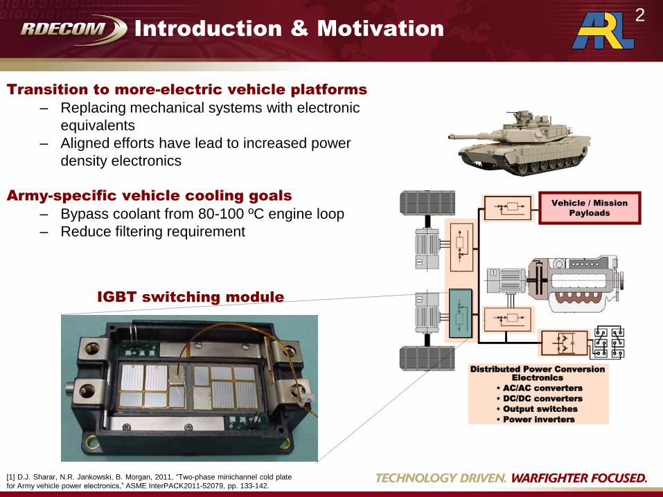
Transition to more-electric vehicle platforms
– Replacing mechanical systems with electronic
equivalents
– Aligned efforts have lead to increased power
density electronics
Army-specific vehicle cooling goals
– Bypass coolant from 80-100 ºC engine loop
– Reduce filtering requirement
IGBT switching module
2
[1] D.J. Sharar, N.R. Jankowski, B. Morgan, 2011, “Two-phase minichannel cold plate
for Army vehicle power electronics,” ASME InterPACK2011-52079, pp. 133-142.
Single- & Two-Phase Predictive
Modeling
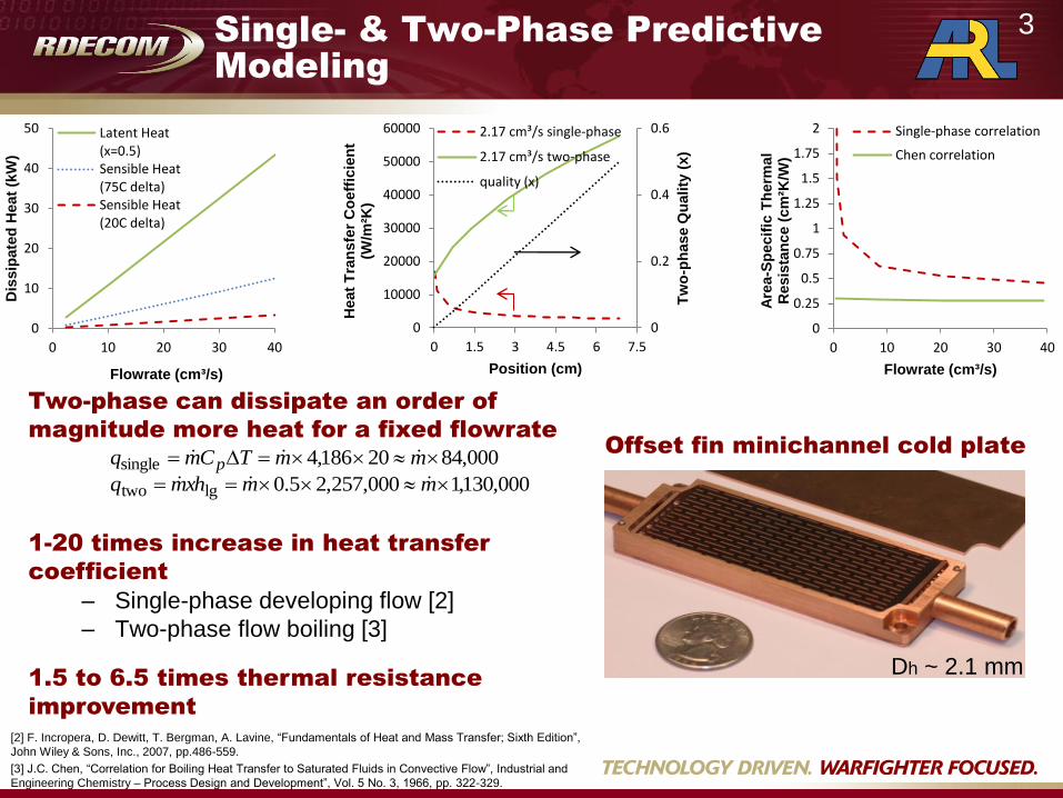
Dh ~ 2.1 mm
Offset fin minichannel cold plate
[2] F. Incropera, D. Dewitt, T. Bergman, A. Lavine, “Fundamentals of Heat and Mass Transfer; Sixth Edition”,
John Wiley & Sons, Inc., 2007, pp.486-559.
[3] J.C. Chen, “Correlation for Boiling Heat Transfer to Saturated Fluids in Convective Flow”, Industrial and
Engineering Chemistry – Process Design and Development”, Vol. 5 No. 3, 1966, pp. 322-329.
Two-phase can dissipate an order of
magnitude more heat for a fixed flowrate
1-20 times increase in heat transfer
coefficient
– Single-phase developing flow [2]
– Two-phase flow boiling [3]
1.5 to 6.5 times thermal resistance
improvement
000,8420186,4single mmTCmq p
000,130,1000,257,25.0lgtwo mmxhmq
0
0.2
0.4
0.6
0
10000
20000
30000
40000
50000
60000
0 1.5 3 4.5 6 7.5
Tw
o-p
hase Q
uality
(x)
Heat
Tra
nsfe
r C
oeff
icie
nt
(W/m
²K)
Position (cm)
2.17 cm³/s single-phase
2.17 cm³/s two-phase
quality (x)
0
0.25
0.5
0.75
1
1.25
1.5
1.75
2
0 10 20 30 40
Are
a-S
pecif
ic T
herm
al
Resis
tan
ce (
cm
²K/W
)
Flowrate (cm³/s)
Single-phase correlation
Chen correlation
0
10
20
30
40
50
0 10 20 30 40
Dis
sip
ate
d H
eat
(kW
)
Flowrate (cm³/s)
Latent Heat (x=0.5) Sensible Heat (75C delta) Sensible Heat (20C delta)
3
Offset Fin Minichannel Cold Plate
Design & Fabrication
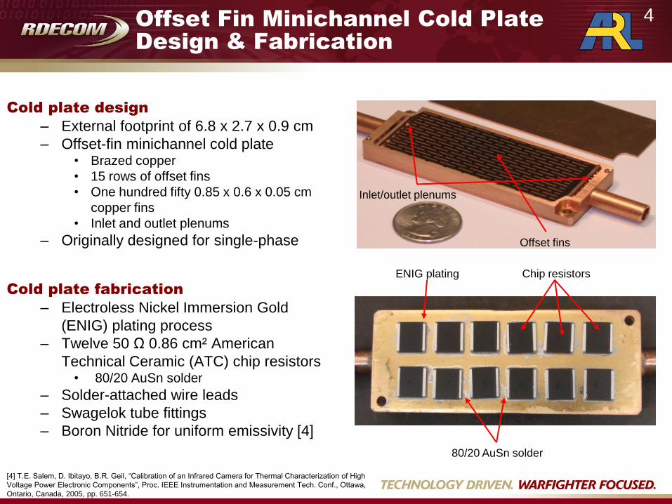
Cold plate design
– External footprint of 6.8 x 2.7 x 0.9 cm
– Offset-fin minichannel cold plate • Brazed copper
• 15 rows of offset fins
• One hundred fifty 0.85 x 0.6 x 0.05 cm
copper fins
• Inlet and outlet plenums
– Originally designed for single-phase
Cold plate fabrication
– Electroless Nickel Immersion Gold
(ENIG) plating process
– Twelve 50 Ω 0.86 cm² American
Technical Ceramic (ATC) chip resistors • 80/20 AuSn solder
– Solder-attached wire leads
– Swagelok tube fittings
– Boron Nitride for uniform emissivity [4]
[4] T.E. Salem, D. Ibitayo, B.R. Geil, “Calibration of an Infrared Camera for Thermal Characterization of High
Voltage Power Electronic Components”, Proc. IEEE Instrumentation and Measurement Tech. Conf., Ottawa,
Ontario, Canada, 2005, pp. 651-654.
Offset fins
Inlet/outlet plenums
ENIG plating Chip resistors
80/20 AuSn solder
4

Experimental Setup and Testing
Procedure
Performance criteria
– Input and output power
– Pressure drop vs flowrate
– Thermal resistivity vs flowrate
– Heat dissipated vs pumping power
– Chip temperature vs downstream position
Test parameters
– 25ºC and 80ºC single-phase water
– 99ºC saturated (two-phase) water
– >1 kW input power
– Flowrates 0-40 cm³/s
– Pressure drop < 35 kPa
Heat pump
Pressure
transducers
Rotameters
Condenser
Inline
heater
Power
supply
Thermal
camera
T1
T2 T3
T4
Experimental setup Test procedure
Test Tfluid in Tchip max ∆Tchip
1phase 80 ºC 100 ºC 20 ºC
2phase 100 ºC 135 ºC 35 ºC
0
20
40
60
80
100
120
140
0 50 100 150 200 250
Ch
ip T
emp
erat
ure
(°C
)
Time (s)
Single-phase 25C Single-phase 80C Two-phase
5
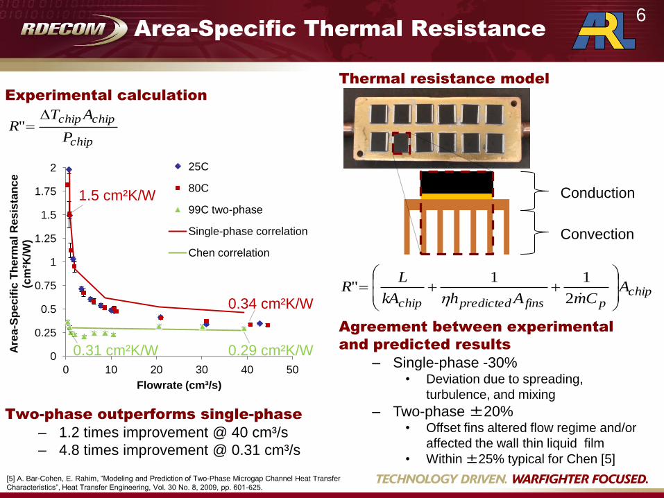
Area-Specific Thermal Resistance
Thermal resistance model
Agreement between experimental
and predicted results
– Single-phase -30% • Deviation due to spreading,
turbulence, and mixing
– Two-phase ±20% • Offset fins altered flow regime and/or
affected the wall thin liquid film
• Within ±25% typical for Chen [5]
chippfinspredictedchip
ACmAhkA
LR
2
11"
Conduction
Convection
[5] A. Bar-Cohen, E. Rahim, “Modeling and Prediction of Two-Phase Microgap Channel Heat Transfer
Characteristics”, Heat Transfer Engineering, Vol. 30 No. 8, 2009, pp. 601-625.
Experimental calculation
Two-phase outperforms single-phase
– 1.2 times improvement @ 40 cm³/s
– 4.8 times improvement @ 0.31 cm³/s
chip
chipchip
P
ATR
"
0
0.25
0.5
0.75
1
1.25
1.5
1.75
2
0 10 20 30 40 50
Are
a-S
pe
cif
ic T
he
rma
l R
es
ista
nc
e
(cm
²K/W
)
Flowrate (cm³/s)
25C
80C
99C two-phase
Single-phase correlation
Chen correlation
0.34 cm²K/W
0.29 cm²K/W
1.5 cm²K/W
0.31 cm²K/W
6

Chip-to-Chip Temperature Variation
Physical causes for diverging
performance
– Single-phase developing flow [2]
– Downstream sensible heating
– Boiling occurs at nearly isothermal
conditions
x=0-0.068 m x*=.613 m
[2] F. Incropera, D. Dewitt, T. Bergman, A. Lavine, “Fundamentals of Heat and Mass Transfer; Sixth Edition”,
John Wiley & Sons, Inc., 2007, pp.486-559.
-9
-6
-3
0
3
6
9
∆T
fro
m A
ve
rag
e
(ºC
)
Chip Location
25C
80C
99C
64W @ 0.4cm³/s
∆T = 15.4 ºC
∆T = 1.50 ºC
x=0.075
Varying levels of temperature non-
uniformity in all tests
– Minimal improvement at high
flowrates
– Order of magnitude improvement
at 64W and 0.40 cm³/s
T
x(m)
7
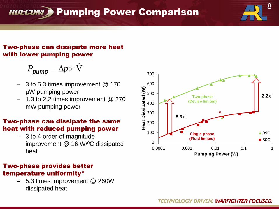
Pumping Power Comparison
V pPpump
Two-phase can dissipate more heat
with lower pumping power
– 3 to 5.3 times improvement @ 170
µW pumping power
– 1.3 to 2.2 times improvement @ 270
mW pumping power
Two-phase can dissipate the same
heat with reduced pumping power
– 3 to 4 order of magnitude
improvement @ 16 W/ºC dissipated
heat
Two-phase provides better
temperature uniformity*
– 5.3 times improvement @ 260W
dissipated heat
0
100
200
300
400
500
600
700
0.0001 0.001 0.01 0.1 1 H
ea
t D
iss
ipa
ted
(W
)
Pumping Power (W)
99C
80C
Two-phase
(Device limited)
Single-phase
(Fluid limited)
2.2x
5.3x
*
8

Outline
Two-phase offset fin minichannel cold plate
•Introduction
•Modeling
•Design and fabrication
•Performance
Two-phase surface enhancements
•Introduction
•Passive techniques
•Nucleate boiling enhancement
•Convective vaporization enhancement
9

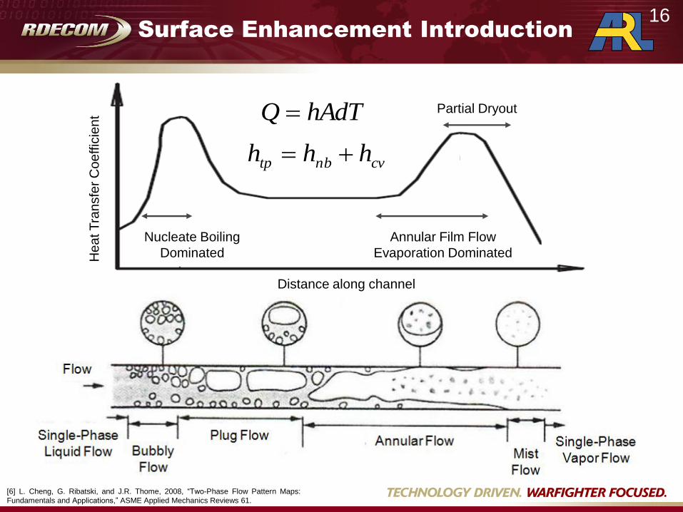
Surface Enhancement Introduction
[6] L. Cheng, G. Ribatski, and J.R. Thome, 2008, “Two-Phase Flow Pattern Maps:
Fundamentals and Applications,” ASME Applied Mechanics Reviews 61.
hAdTQ
cvnbtp hhh
Distance along channel
He
at T
ran
sfe
r C
oe
ffic
ien
t
Nucleate Boiling
Dominated
Annular Film Flow
Evaporation Dominated
Partial Dryout
10
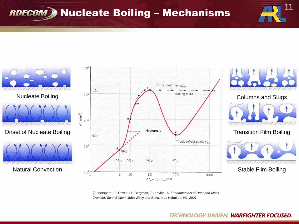
Nucleate Boiling – Mechanisms
[2] Incropera, F.; Dewitt, D.; Bergman, T.; Lavine, A. Fundamentals of Heat and Mass
Transfer: Sixth Edition; John Wiley and Sons, Inc.: Hoboken, NJ, 2007.
Natural Convection
Onset of Nucleate Boiling
Nucleate Boiling Columns and Slugs
Transition Film Boiling
Stable Film Boiling
Hysteresis
11

Nucleate Boiling – Mechanisms
[2] Incropera, F.; Dewitt, D.; Bergman, T.; Lavine, A.
Fundamentals of Heat and Mass Transfer: Sixth Edition;
John Wiley and Sons, Inc.: Hoboken, NJ, 2007.
Bubble development, growth, and
departure from a nucleation site
Hysteresis
Effect of populating
heated surface with
nucleation sites
12
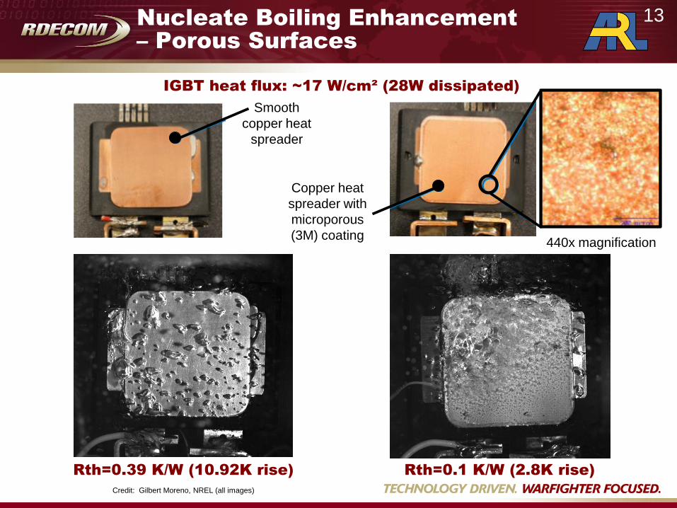
Nucleate Boiling Enhancement
– Porous Surfaces
Credit: Gilbert Moreno, NREL (all images)
Smooth
copper heat
spreader
Copper heat
spreader with
microporous
(3M) coating 440x magnification
IGBT heat flux: ~17 W/cm² (28W dissipated)
Rth=0.39 K/W (10.92K rise) Rth=0.1 K/W (2.8K rise)
13
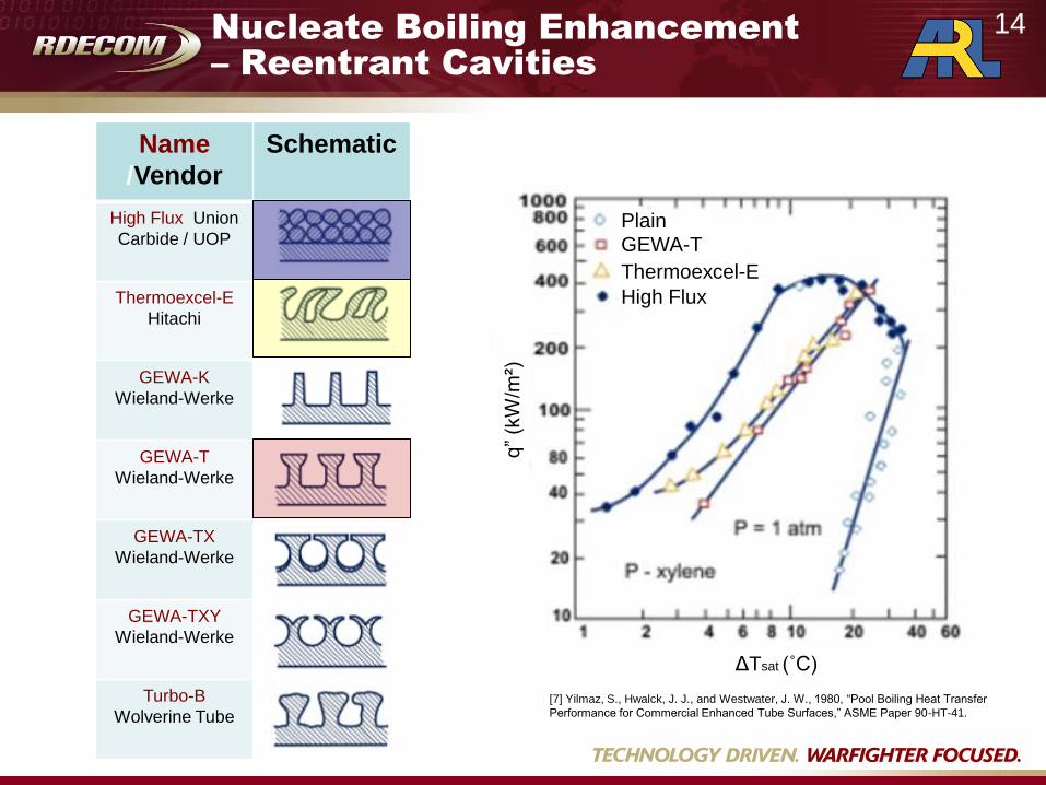
Name
/Vendor
Schematic
High Flux Union
Carbide / UOP
Thermoexcel-E
Hitachi
GEWA-K
Wieland-Werke
GEWA-T
Wieland-Werke
GEWA-TX
Wieland-Werke
GEWA-TXY
Wieland-Werke
Turbo-B
Wolverine Tube
[7] Yilmaz, S., Hwalck, J. J., and Westwater, J. W., 1980, “Pool Boiling Heat Transfer
Performance for Commercial Enhanced Tube Surfaces,” ASME Paper 90-HT-41.
q”
(kW
/m²)
ΔTsat (˚C)
Plain GEWA-T
Thermoexcel-E
High Flux
Nucleate Boiling Enhancement
– Reentrant Cavities
14

Nucleate Boiling Enhancement
– Nanoparticle Fluid Additives
Pure water
2
-5 TiO %10
2
-4 TiO %10
2
-3 TiO %10
2
-2 TiO %10
2
-1 TiO %10
Additional nanoparticle fluid additives:
– Al2O3 [9] S.M. You, J.H. Kim, K.H. Kim, 2003, “Effect of nanoparticles on
critical heat flux of water in pool boiling heat transfer,” Appl. Phys. Lett. 83 pp.
3374–3376.
– SiO2 [10] P. Vassallo, R. Kumar, S. D’Amico, 2004, “Pool boiling heat
transfer experiments in silica-water nano-fluids,” Int. J. Heat Mass Transfer 47,
pp. 407-411.
– Fe [11] M.H. Shi, M.Q. Shuai, Z.Q. Chen, Q. Li, and Y. Xuan, 2007, “Sudy on
Pool Boiling Heat Transfer of Nano-Particle Suspensions on Plate Surface,” J. of
Enhanced Heat Transfer 14, pp. 223-231.
[8] H. Kim, J. Kim, M.H. Kim, 2006, “Effect of nanoparticles on CHF enhancement in pool boiling
of nano-fluids,” Int. J. of Heat and Mass Transfer 49, pp. 5070-5074.
15
Surface Enhancement Introduction
[6] L. Cheng, G. Ribatski, and J.R. Thome, 2008, “Two-Phase Flow Pattern Maps:
Fundamentals and Applications,” ASME Applied Mechanics Reviews 61.
hAdTQ
cvnbtp hhh
Distance along channel
He
at T
ran
sfe
r C
oe
ffic
ien
t
Nucleate Boiling
Dominated
Annular Film Flow
Evaporation Dominated
Partial Dryout
16
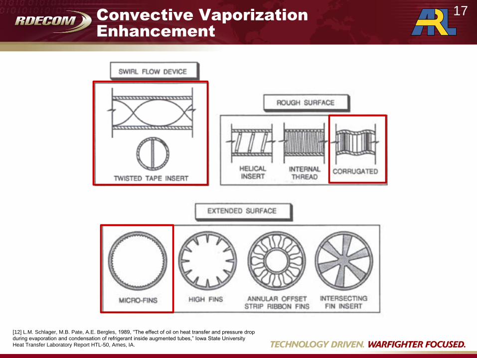
Convective Vaporization
Enhancement
[12] L.M. Schlager, M.B. Pate, A.E. Bergles, 1989, “The effect of oil on heat transfer and pressure drop
during evaporation and condensation of refrigerant inside augmented tubes,” Iowa State University
Heat Transfer Laboratory Report HTL-50, Ames, IA.
17
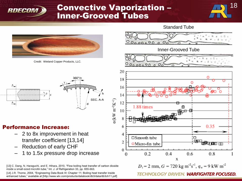
Convective Vaporization –
Inner-Grooved Tubes
[13] C. Dang, N. Haraguchi, and E. Hihara, 2010, “Flow boiling heat transfer of carbon dioxide
inside a small-sized microfin tube,” Int. J. of Refrigeration 33, pp. 655-663.
[14] J.R. Thome, 2004, “Engineering Data Book III: Chapter 11; Boiling heat transfer inside
enhanced tubes,” available at [http://www.wlv.com/products/databook/db3/data/db3ch11.pdf]
Credit: Wieland Copper Products, LLC.
Performance Increase:
– 2 to 8x improvement in heat
transfer coefficient [13,14]
– Reduction of early CHF
– 1 to 1.5x pressure drop increase
Standard Tube
Inner-Grooved Tube
18
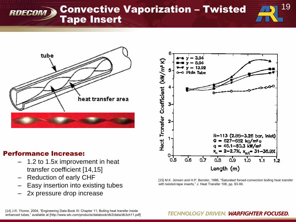
Convective Vaporization – Twisted
Tape Insert
Performance Increase:
– 1.2 to 1.5x improvement in heat
transfer coefficient [14,15]
– Reduction of early CHF
– Easy insertion into existing tubes
– 2x pressure drop increase
[15] M.K. Jensen and H.P. Bensler, 1986, “Saturated forced-convection boiling heat transfer
with twisted-tape inserts,” J. Heat Transfer 108, pp. 93-99.
19
[14] J.R. Thome, 2004, “Engineering Data Book III: Chapter 11; Boiling heat transfer inside
enhanced tubes,” available at [http://www.wlv.com/products/databook/db3/data/db3ch11.pdf]

Convective Vaporization–
Corrugated Tubes
Performance Increase:
– 1.2 to 1.8x improvement in heat
transfer coefficient [14,16]
– Reduction of early CHF
– 2x pressure drop increase
[16] S. Laohalertdecha and S. Wongwises, 2011, “An experimental study into the
evaporation heat transfer and flow characteristics of R-134a refrigerant flow ing
through corrugated tubes,” Int. J. of Refrigeration 34, pp. 280-291.
20
[14] J.R. Thome, 2004, “Engineering Data Book III: Chapter 11; Boiling heat transfer inside
enhanced tubes,” available at [http://www.wlv.com/products/databook/db3/data/db3ch11.pdf]

Convective Boiling Enhancement –
Microfin/Microchannel Structures
Micro pin-fin heat sink
[18] S. Krishnamurthy and Y. Peles, 2008, “Flow boiling of water in a circular
staggered micro-pin fin heat sink,” Int. J. of Heat and Mass Transfer 51, pp. 1349-
1364.
Microchannel heat sink
200µm
Typical Macrochannel Flow Regimes
Typical Microchannel Flow Regimes
[17] B. Agostini, J.R. Thome, M. Fabbri, B. Michel, D. Calmi, and U.
Kloter, 2008, “High heat flux flow boiling in silicon multi-microchannels –
Part I: Heat transfer characteristics of refrigerant R236fa,” Int. J. of Heat
and Mass Transfer 51, pp. 5400-5414.
21
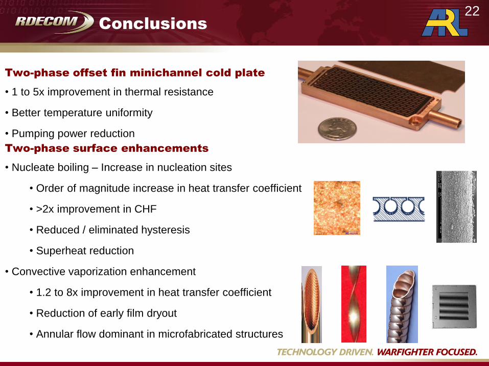
Conclusions
Two-phase offset fin minichannel cold plate
• 1 to 5x improvement in thermal resistance
• Better temperature uniformity
• Pumping power reduction
Two-phase surface enhancements
• Nucleate boiling – Increase in nucleation sites
• Order of magnitude increase in heat transfer coefficient
• >2x improvement in CHF
• Reduced / eliminated hysteresis
• Superheat reduction
• Convective vaporization enhancement
• 1.2 to 8x improvement in heat transfer coefficient
• Reduction of early film dryout
• Annular flow dominant in microfabricated structures
22

References
[1] D.J. Sharar, N.R. Jankowski, B. Morgan, 2011, “Two-phase minichannel cold plate for Army vehicle power electronics,” ASME InterPACK2011-52079, pp.
133-142.
[2] F. Incropera, D. Dewitt, T. Bergman, A. Lavine, “Fundamentals of Heat and Mass Transfer; Sixth Edition”, John Wiley & Sons, Inc., 2007, pp.486-559.
[3] J.C. Chen, “Correlation for Boiling Heat Transfer to Saturated Fluids in Convective Flow”, Industrial and Engineering Chemistry – Process Design and
Development”, Vol. 5 No. 3, 1966, pp. 322-329.
[4] T.E. Salem, D. Ibitayo, B.R. Geil, “Calibration of an Infrared Camera for Thermal Characterization of High Voltage Power Electronic Components”, Proc.
IEEE Instrumentation and Measurement Tech. Conf., Ottawa, Ontario, Canada, 2005, pp. 651-654.
[5] A. Bar-Cohen, E. Rahim, “Modeling and Prediction of Two-Phase Microgap Channel Heat Transfer Characteristics”, Heat Transfer Engineering, Vol. 30 No.
8, 2009, pp. 601-625.
[6] L. Cheng, G. Ribatski, and J.R. Thome, 2008, “Two-Phase Flow Pattern Maps: Fundamentals and Applications,” ASME Applied Mechanics Reviews 61.
[7] Yilmaz, S., Hwalck, J. J., and Westwater, J. W., 1980, “Pool Boiling Heat Transfer Performance for Commercial Enhanced Tube Surfaces,” ASME Paper 90-
HT-41.
[8] H. Kim, J. Kim, M.H. Kim, 2006, “Effect of nanoparticles on CHF enhancement in pool boiling of nano-fluids,” Int. J. of Heat and Mass Transfer 49, pp. 5070-
5074.
[9] S.M. You, J.H. Kim, K.H. Kim, 2003, “Effect of nanoparticles on critical heat flux of water in pool boiling heat transfer,” Appl. Phys. Lett. 83 pp. 3374–3376.
[10] P. Vassallo, R. Kumar, S. D’Amico, 2004, “Pool boiling heat transfer experiments in silica-water nano-fluids,” Int. J. Heat Mass Transfer 47, pp. 407-411
[11] M.H. Shi, M.Q. Shuai, Z.Q. Chen, Q. Li, and Y. Xuan, 2007, “Sudy on Pool Boiling Heat Transfer of Nano-Particle Suspensions on Plate Surface,” J. of
Enhanced Heat Transfer 14, pp. 223-231.
[12] L.M. Schlager, M.B. Pate, A.E. Bergles, 1989, “The effect of oil on heat transfer and pressure drop during evaporation and condensation of refrigerant inside
augmented tubes,” Iowa State University Heat Transfer Laboratory Report HTL-50, Ames, IA.
[13] C. Dang, N. Haraguchi, and E. Hihara, 2010, “Flow boiling heat transfer of carbon dioxide inside a small-sized microfin tube,” Int. J. of Refrigeration 33, pp.
655-663.
[14] J.R. Thome, 2004, “Engineering Data Book III: Chapter 11; Boiling heat transfer inside enhanced tubes,” available at
[http://www.wlv.com/products/databook/db3/data/db3ch11.pdf]
[15] M.K. Jensen and H.P. Bensler, 1986, “Saturated forced-convection boiling heat transfer with twisted-tape inserts,” J. Heat Transfer 108, pp. 93-99.
[16] S. Laohalertdecha and S. Wongwises, 2011, “An experimental study into the evaporation heat transfer and flow characteristics of R-134a refrigerant flow ing
through corrugated tubes,” Int. J. of Refrigeration 34, pp. 280-291.
[17] B. Agostini, J.R. Thome, M. Fabbri, B. Michel, D. Calmi, and U. Kloter, 2008, “High heat flux flow boiling in silicon multi-microchannels – Part I: Heat transfer
characteristics of refrigerant R236fa,” Int. J. of Heat and Mass Transfer 51, pp. 5400-5414
[18] S. Krishnamurthy and Y. Peles, 2008, “Flow boiling of water in a circular staggered micro-pin fin heat sink,” Int. J. of Heat and Mass Transfer 51, pp. 1349-
1364.
23
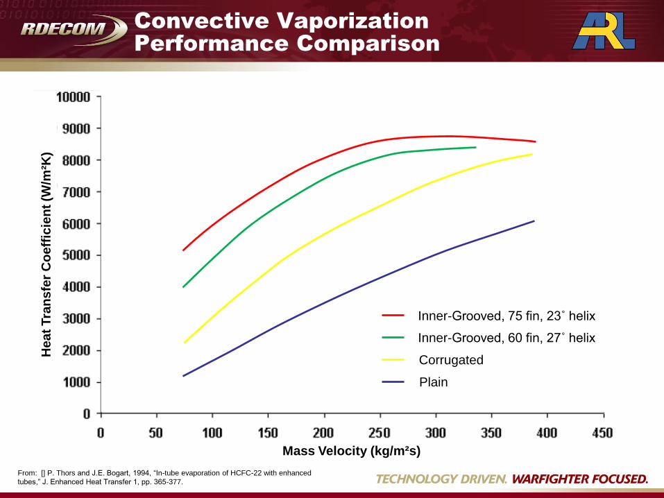
Convective Vaporization
Performance Comparison
Inner-Grooved, 75 fin, 23˚ helix
Inner-Grooved, 60 fin, 27˚ helix
Corrugated
Plain
From: [] P. Thors and J.E. Bogart, 1994, “In-tube evaporation of HCFC-22 with enhanced
tubes,” J. Enhanced Heat Transfer 1, pp. 365-377.
He
at
Tra
ns
fer
Co
eff
icie
nt
(W/m
²K)
Mass Velocity (kg/m²s)