design and construction techniques for permeable reactive barriers
TRANSCRIPT

Ž .Journal of Hazardous Materials 68 1999 41–71www.elsevier.nlrlocaterjhazmat
Design and construction techniques for permeablereactive barriers
Arun R. Gavaskar )
Battelle Memorial Institute, 505 King AÕenue, Columbus, OH 43201-2693, USA
Abstract
Adequate site characterization, bench-scale column testing, and hydrogeologic modelingformed the basis for the design and construction of permeable reactive barriers for groundwaterremediation at various sites, such as Dover Air Force Base, DE and Naval Air Station, Moffett
Ž .Field, CA. Dissolved chlorinated solvents, such as perchloroethylene PCE and trichloroethyleneŽ .TCE , have been the focus at many sites because the passive nature of the reactive barrieroperation makes such barriers particularly useful for treating groundwater contaminants that canpersist in the aquifer for several years. A combination of conventional and innovative sitecharacterization, design, and construction techniques were used at these sites to increase thepotential cost effectiveness of field application. q 1999 Elsevier Science B.V. All rights reserved.
Keywords: Permeable reactive barriers; Perchloroethylene; Trichloroethylene
1. Introduction
Permeable reactive barriers are an emerging alternative to pump-and-treat systems forŽ .treating groundwater contamination. The main advantage of a reactive barrier Fig. 1 is
the passive nature of the treatment. That is, for the most part, its operation does notdepend on any external labor or energy inputs. Once installed, the barrier takesadvantage of the in situ groundwater flow to bring the contaminants in contact with the
w x w xreactive material. Considerable research 1,2 , some field-pilot tests 3 , and a few
) Tel.: q1-614-424-2403; fax: q1-614-424-3667.
0304-3894r99r$ - see front matter q 1999 Elsevier Science B.V. All rights reserved.Ž .PII: S0304-3894 99 00031-X

( )A.R. GaÕaskarrJournal of Hazardous Materials 68 1999 41–7142
Fig. 1. Different permeable reactive barrier configurations for groundwater treatment.
full-scale applications have been conducted over the last 5 years to demonstrate thepotential of this technology. A passive treatment system is especially desirable forcontaminants such as chlorinated solvents, where the plume is likely to persist forseveral hundred years.
The reactive material used in the barrier may vary depending on the type ofcontaminants being treated. The most common reactive medium used so far has beengranular iron. Zero-valent iron is a strong reducing agent that can abiotically reduce
Ž . Ž .dissolved contaminants, such as perchloroethylene PCE , trichloroethylene TCE , andother chlorinated solvents.
3Fe0 qC HCl q3Hq™3Fe2qqC H q3Cly 1Ž .2 3 2 4
Ethene and ethane are the main products of TCE degradation. However, indications arethat these final reaction products are generated through multiple pathways. By the

( )A.R. GaÕaskarrJournal of Hazardous Materials 68 1999 41–71 43
Ž .hydrogenolysis pathway, TCE degrades to cis-1,2-dichloroethylene DCE , which inŽ .turn degrades to vinyl chloride VC . Both DCE and VC are fairly persistent under the
reducing conditions of the iron medium and degrade to ethene and ethane relativelyslowly. Fortunately, only 5% or less of TCE appears to take this pathway. Most of the
w xTCE appears to degrade to ethene and ethane by the beta-elimination pathway 4 ,through the formation of intermediates, such as acetylene. These intermediates areshort-lived and quickly degrade to ethene and ethane.
Other contaminants, such as dissolved chromium and uranium, which are amenable toreduction by iron can also be treated by precipitating them out of the groundwater.
The groundwater itself may have some native constituents, such as dissolved oxygenŽ .DO or carbonates, which react with and consume the reactive medium. Water itself isreduced, although slowly, by zero-valent metals such as iron.
2Fe0 qO q2H O™2Fe2qq4OHy 2Ž .2 2
HCOy qOHy™CO2y qH O 3Ž .3 3 2
Fe0 q2H O™Fe2qqH qOHy 4Ž .2 2
These inorganic constituents could potentially affect the reactive and hydrologic proper-ties of the reactive medium. A possible scenario can be envisioned whereby precipitationof hydroxides and carbonates causes loss of reactive surfaces and reduction in hydraulicconductivity of the reactive medium. This could affect the operation of the barrier bycausing the plume to break through or bypass the reactive medium. However, a reactive
w xiron barrier that was installed 5 years ago at Borden, Canada 1 has yet to show anysignificant effects from such precipitation reactions. With new research underway torejuvenate the reactivity and hydrologic characteristics of a reactive barrier withoutresorting to excavation and replacement of the reactive medium, it is hoped that anymaintenance required in the future will be relatively infrequent and inexpensive.
The design of a permeable barrier should account for all these variables, includingcontaminant degradation rates, groundwater flow, and native groundwater constituents.
2. Barrier design
Fig. 2 shows the steps in the design of a permeable reactive barrier. These stepsinvolve the determination of:Ø Suitability of a site for permeable reactive barrier application,Ø Site characteristics affecting barrier design,
Ž .Ø Reaction rates or half-lives through column testing ,Ø Location, configuration, and dimensions of the barrier,Ø Longevity,Ø Monitoring strategy,Ø Cost.

( )A.R. GaÕaskarrJournal of Hazardous Materials 68 1999 41–7144
Fig.
2.St
eps
inth
ede
sign
ofa
perm
eabl
ere
activ
eba
rrie
r.
( )A.R. GaÕaskarrJournal of Hazardous Materials 68 1999 41–71 45
2.1. Preliminary site assessment
Generally, a review of existing site documents, such as RCRA Facility InvestigationŽ . Ž .RFI or Remedial InvestigationrFeasibility Study RIrFS reports, and a visualexamination of the layout of the site form the basis for a preliminary assessment of thefeasibility of a permeable reactive barrier. Existing site documents may be scrutinizedfor the following information.
Ø Types of contaminants. Are the contaminants suitable for degradation by materials,such as iron, that are usable in a permeable barrier. Of course, newer reactive materials
Ž .could be developed for specific contaminants. But so far, reactive metals e.g. iron andŽ .magnesium dioxide oxygen provider have typically been used in field barriers.
Ø Contaminant distribution. Although the plume and aquifer dimensions are not aninsurmountable hurdle, very deep plumes or very wide plumes can increase the barriercost. That being said, barriers have so far been applied to plumes that are as wide as
Ž . Ž1000 ft. at the Denver Federal Center and as deep as 40 to 50 ft. deep Dover Air.Force Base and Somersworth Landfill Site . Innovative installation techniques, such as
jetting and hydrofracturing, appear promising for overcoming the depth limitation. Acompetent aquitard is desirable so that the barrier can be keyed in. Hanging barriersŽ .barriers that are not keyed into the aquitard have been modeled, but great cautionwould be necessary in the field to ensure that the plume does not find a way under thebarrier.
Ø Groundwater Õelocity. Extremely fast-moving groundwater may require a thickerŽbarrier to ensure adequate residence time contact time between the contaminants and
.the reactive medium and this may increase cost. Extremely slow-moving or stationarygroundwater may prevent contaminants from coming into contact with the reactivemedium in any reasonable time frame. Most sites are likely to be between these twoextremes.
Ø Geotechnical considerations. Access to the plume is a major consideration forapplication of a permeable barrier. An overlying building or a plume that has moved offproperty boundaries are factors that may limit access to the plume. Underground utilitylines can make installation of a barrier difficult. The presence of cobbles or highlyconsolidated sediments in the subsurface may impede installation equipment.
None of these factors are insurmountable, but it is important to consider them so thata realistic preliminary assessment of the technical, economic, and administrative feasibil-ity of a permeable barrier is obtained for the site. Prospective locations for the barrierare generally established at this stage.
2.2. Site characterization
Unlike a pump-and-treat system, which can be relocated or scaled up or otherwisemodified after installation, a permeable barrier is a more or less permanent structure.Once placed in the ground, it would be difficult and expensive to relocate or modify.Therefore, a good understanding of the aquifer and plume characteristics is necessary toenable a good barrier design. Usually, this requires some additional site characterization

( )A.R. GaÕaskarrJournal of Hazardous Materials 68 1999 41–7146
with emphasis on the regions surrounding prospective barrier locations. A good concep-tual and, most often, a computerized model of the groundwater flow system should begenerated with the site characterization data to aid in the design.
The first and foremost site characteristic that should be properly defined, if notalready done, is the exact distribution of the contaminants. This includes both thehorizontal and vertical extent of the plume. The plume may be defined by one or, atmany sites, multiple contaminants. Because achieving maximum contaminant levelsŽ .MCLs for the target contaminants is usually the treatment goal, the outer edges of theplume are defined by these concentrations. Mapping the contaminant distribution well isimportant for several reasons. It helps in designing a location and configuration of thebarrier that optimizes the treatment process. For example, at the Naval Air Station,Moffett Field, CA site, the plume was several hundred feet wide. However, most of thecontamination appeared to be flowing through discrete sand channels. In this situation, afunnel and gate system with the gate located in the sand channel and the funnel coveringthe surrounding fine-grained sediments was found to be an efficient way of capturingand treating the contamination.
Aquifer characteristics are important to define at a localized level in the vicinity ofthe prospective barrier location. The operation of the barrier depends on the ability ofthe targeted portion of the groundwater to flow through the reactive cell. If the flowcharacteristics are poorly understood, the permeable barrier may not efficiently performits hydrogeologic function of channeling the targeted groundwater through the reactivecell.
The required aquifer information includes the distribution of different hydrostrati-graphic units and the hydrologic flow characteristics. Mapping out variations in depth,thickness, and water levels of various hydrostratigraphic units in the subsurface in thevicinity of the barrier is important in design and construction of the barrier. This can bedone by drilling and sampling several locations using a conventional drill rig. Recently,
Ž .new direct push methods such as cone penetrometer testing CPT and GeoProbee havebeen used at several sites. These new techniques are quicker than conventional drillingand are useful for mapping localized heterogeneities in the immediate vicinity of theprospective barrier location. These heterogeneities can then be inserted into the ground-water flow model developed for the site.
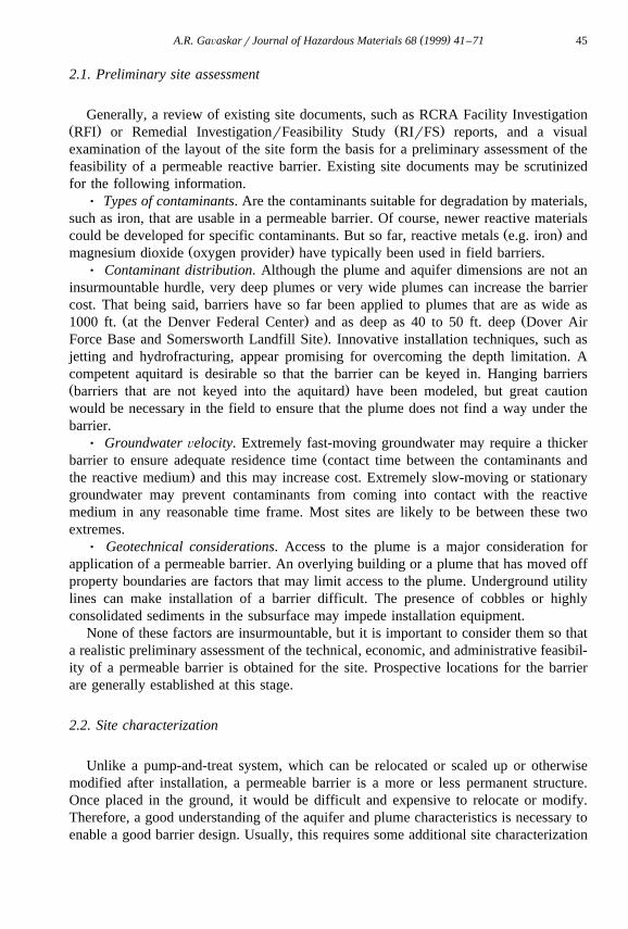
Fig. 3 shows a geologic cross-section prepared as a result of CPT work conducted atthe Dover Air Force Base barrier site. The CPT incorporates a specially-instrumentedpush rod that is capable of physical measurements, such as tip stress, pore pressure, andfriction ratio, that are indicative of different geologic zones. By pushing the CPT rod inmultiple locations, the geologic map depicted in Fig. 3 was prepared. It identifiesvariations in aquitard depth and shows a few clay lenses near the water table. Waterlevels were measured during the CPT work by installing hollow tubes screened atappropriate depths. These rods also served as temporary wells for collecting groundwa-ter samples for mapping the plume. After measuring water level measurement andsampling groundwater, these tubes were pulled out of the ground and the holes weregrouted. Based on historical data, the water levels under seasonal high and low flowconditions were also plotted on the same cross-section. This hydrostratigraphic map wasused to determine the depths of the top and bottom of the barrier. At the Moffett Field
()
A.R
.GaÕaskarr
JournalofH
azardousM
aterials68
199941
–71
47
Fig. 3. A geologic cross-section depicting the region in the immediate vicinity of a permeable barrier at Dover Air Force Base.

( )A.R. GaÕaskarrJournal of Hazardous Materials 68 1999 41–7148
Fig. 4. Locating the gate of a funnel-and-gate system in a sand channel at Moffett Field.
Ž .site, CPT work was used to identify the exact location of a sand channel see Fig. 4through which most of the contaminated groundwater was flowing. Consequently, thereactive cell was installed in this sand channel. At both sites, localized CPT datasupplemented data from more widely-dispersed conventional wells present on theproperty.
2.3. Reaction rates or half-liÕes of contaminants
Reaction rates or half-lives of contaminants in contact with the reactive medium arenecessary to determine the reactive cell thickness that will provide adequate residencetime for the contaminants to degrade to their MCLs. Both batch and continuous columntests have been used in the past to determine reaction rates. Because continuous testsbetter simulate the dynamic groundwater flow environment, testing in columns is by farthe most common method.
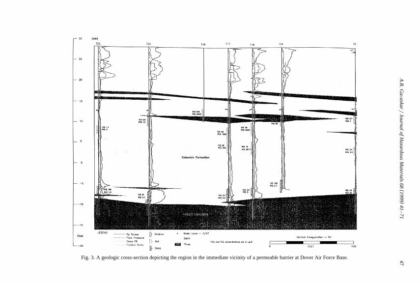
2.3.1. Test materials and methodsColumn testing is a better way of estimating reaction rates. The design of the column
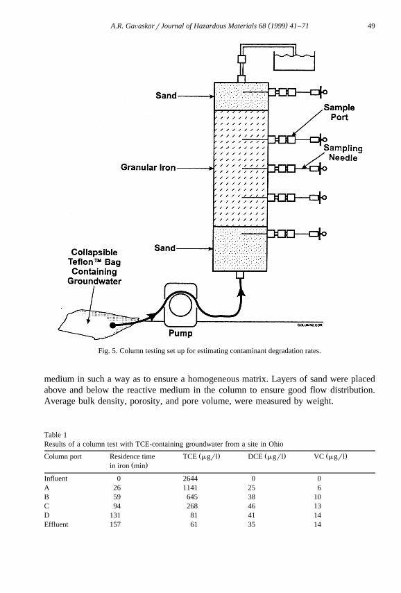
apparatus used in a recent test with TCE-containing groundwater obtained from a site inOhio is shown in Fig. 5. The resulting concentration vs. time data are shown in Table 1.The column was made from Plexiglase. Strictly speaking, glass should be expected tohave the least adsorptive or reactive effect with chlorinated organic compounds;however, no significant loss of organics has been reported using Plexiglase columns.All fittings were stainless steel. Tubing is either stainless steel or Teflone. A smallsection of tubing through the peristaltic pump was made of Vitone for more flexibility.
Ž .The reactive medium used in this test was granular iron Peerless Metal Products inthe y8q50-mesh particle size range. The column was packed with the reactive
( )A.R. GaÕaskarrJournal of Hazardous Materials 68 1999 41–71 49
Fig. 5. Column testing set up for estimating contaminant degradation rates.
medium in such a way as to ensure a homogeneous matrix. Layers of sand were placedabove and below the reactive medium in the column to ensure good flow distribution.Average bulk density, porosity, and pore volume, were measured by weight.
Table 1Results of a column test with TCE-containing groundwater from a site in Ohio
Ž . Ž . Ž .Column port Residence time TCE mgrl DCE mgrl VC mgrlŽ .in iron min
Influent 0 2644 0 0A 26 1141 25 6B 59 645 38 10C 94 268 46 13D 131 81 41 14Effluent 157 61 35 14

( )A.R. GaÕaskarrJournal of Hazardous Materials 68 1999 41–7150
The feed water was placed in a collapsible Teflone bag to prevent headspace as thebag emptied out. The bag was filled by gravity flow to avoid aeration of the water.Water was circulated in the column from bottom to top to better simulate the flowrateslikely to be encountered in the field. Sampling ports were equipped with gastight andwatertight fittings. A nylon swage lock fitting was used on the sample port. Thesampling syringe needles remained inserted into the column during the test, with the tipat the center of the column. Valves with luer lock adapters were attached to theprotruding ends of the needles outside the column. A luer lock plug was used to seal theneedle between samples.
Sampling began only after the concentration distribution in the column had reachedsteady state; that is, the net contaminant mass entering the column was equal to the massdegraded in the column. About 40 pore volumes of contaminated water were required to
w xbe run through the column before it reached steady state. Prior research 5 shows thatŽ .the time or number of pore volumes of groundwater flow required to reach steady state
varies with contaminant type. For example, water contaminated with PCE requires alonger time to reach steady state than does water contaminated with TCE.
Whenever a sample was to be drawn, a syringe was attached to the luer lock adapteron the needle and the sample was collected after a small amount of water is purged fromthe needle. The sample was drawn very slowly to create minimum disturbance in theflow. Most researchers conduct column experiments at room temperature. It is importantto note, however, that temperature may be an important factor influencing reaction rate.
The flowrate through the columns was set to simulate site conditions. Therefore, it isdesirable to have good groundwater velocity data from the site at the location of theproposed barrier. Also taken into account was the fact that local groundwater velocitythrough the permeable barrier may be different from that in the surrounding aquifer.Actual flowrates through the column were measured by collecting a timed volume ofeffluent. The experiment was repeated over a range of flowrates to account for seasonalvariations and other uncertainties. However, flowrate may not be a critical parameter for
w xcolumn testing. Prior research 6 indicates that degradation rates were insensitive toŽ .flowrates in the range tested 59 to 242 cmrday . However, designing the flow through
thickness of the reactive cell does require an accurate estimate of groundwater velocity.ŽConcentration profiles plots of TCE concentration vs. time or distance in the iron
.zone were generated periodically for the chlorinated organics distribution in the columnby collecting and analyzing samples from the influent, the effluent, and the intermediate
Ž .sample ports after every 5 to 10 pore volumes. Redox potential Eh and pH profiles ofthe column were generated less frequently because of the higher sample volumesrequired for taking these measurements with typical probes. The column influent and
Ž .effluent were analyzed for inorganics, such as major cations Ca, Mg, Mn and majorŽ . Ž .anions Cl, SO , and NO , and alkalinity bicarbonate .4 3
Analysis of water samples collected from the column was done by the same generalmethods used for analyzing groundwater samples during site characterization. Concen-trations of chlorinated VOCs were measured using a gas chromatograph–flame ioniza-
Ž .tion detector GC-FID with purge and trap equipment. Water samples typically aredrawn through sampling needles into a gastight syringe and are injected directly into thepurge and trap through luer-lock adapters. Although chlorinated compounds can be

( )A.R. GaÕaskarrJournal of Hazardous Materials 68 1999 41–71 51
Ž .detected using an electron capture detector ECD , the GC-FID is suitable for general-purpose work because it can detect both a broad range of low-molecular-weight
Ž .chlorinated compounds e.g. TCE, DCE, and VC , as well as nonchlorinated hydrocar-bon byproducts such as ethene or ethane. The instrument was calibrated to detectcompounds at the lowest concentrations feasible. A typical detection limit for chlori-nated hydrocarbons is 2 mgrl, provided that there is no strong matrix interference thatrequires dilution of the primary sample.
Ž .Anions were measured using ion chromatography IC and cations by inductivelyŽ .coupled plasma ICP . Eh and pH were measured by inserting combination electrodes in
a flow-through cell, into which water withdrawn from one of the column ports wascirculated.
2.3.2. Interpretation of column test resultsŽ .Strictly by Eq. 1 , the reaction rate appears to depend on the concentrations of TCE,
Fe0, and Hq. However, assuming an abundance of Fe0 and Hq relative to TCE, thereaction rate can be viewed as dependent primarily on the concentration of TCE, thus,making it a pseudo-first order reaction.
TCE™Degradation products 5Ž .
Previous research has indicated the validity of this pseudo first-order assumption of thew xdegradation reaction of chlorinated organic compounds with iron 7,2 . Therefore, the
Ž . Ž . Žreaction rate r can be expressed in terms of the concentration C of the reactant say. Ž .TCE and the reaction rate constant k .
ydCyrs skC 6Ž .
d t
Therefore,
CsC eyk t 7Ž .o
Or,
ln CrC sykt 8Ž . Ž .o
C is the initial concentration of TCE; that is, the concentration in the groundwatero
entering the reactive iron zone. It should be noted that because TCE is being degradedby two competing pathways, k is the sum of the rate constants. The flow of groundwaterthrough the iron-filled column is assumed to be plug flow, which means that allelements of the influent groundwater experience the same residence time in the column.
The concentrations of TCE, DCE, and VC measured in the influent and effluent andin ports A, B, C, and D in the reactive iron zone are plotted on the graph shown in Fig.6a. The x-axis can represent the linear distance traveled by the groundwater from theinlet end of the iron zone or the residence time of the groundwater in the iron zone. Theresidence times in Table 1 were obtained from measurements of the volumetric flowrate

( )A.R. GaÕaskarrJournal of Hazardous Materials 68 1999 41–7152
Fig. 6. Plots of chlorinated VOC concentration vs. residence time in the reactive iron.
Ž . Ž .Q , the linear distance traveled in the iron zone L , the cross-sectional area of theŽ . Ž .column A , and the porosity n by the equation:
LAnts 9Ž .
Q
Ž .If instead of plotting C, as in Fig. 6a, ln CrC is plotted against residence time as ino
Fig. 6c, the slope of the regression line represents the reaction rate constant k, based onŽ .Eq. 8 . For the groundwater from this test site, the slope or k was 0.025rmin for TCE.
Ž 2 .The goodness of fit R of the linear regression line is almost 0.99 indicating first-orderkinetics.
Another way of expressing the reaction rate of TCE is in terms of its half-life withrespect to iron. The half-life is the time it takes to reduce the concentration of TCE to
Ž . Ž .half its initial value, that is for Cs0.5 C . Rearranging Eq. 8 , the half-life can beo
represented as:
ln 2t s 10Ž .0.5 k

( )A.R. GaÕaskarrJournal of Hazardous Materials 68 1999 41–71 53
For the particular type of iron used with the groundwater from the Ohio site, the half-lifefor TCE was estimated as 28 min. It should be noted that because of multiple reactionpathways, the k for TCE degradation is in reality the sum of the individual reactionrates, k and k , from the following parallel pathways:1 11
k1
TCE™Hydrogenolysis reaction products 11Ž .k11
TCE™Betayelimination reaction products 12Ž .The estimation of reaction rates or half-lives for DCE and VC is not as straightfor-
ward, since they are produced as a result of hydrogenolysis of TCE, but are themselvesdegraded. Fig. 6b shows a close-up of the DCE and VC curves in Fig. 6a. Thegeneration and degradation of DCE can be represented by the first-order series reactions,
k k1 2
TCE™DCE™VC 13Ž .The concentration of DCE at time, t, can be represented by:
r sk C yk C 14Ž .DCE 1 TCE 2 DCE
However, from a practical sense, since it is k that is determined experimentally and notk , it would be difficult to estimate both k and k empirically. Therefore, the following1 1 2
simplified approach is used for estimating the half-life of DCE.As seen in Fig. 6b, until about 94 min, the concentration of DCE continued to rise.
As TCE was depleted, the rate of degradation of DCE overtook the rate of generation ofDCE, and the DCE concentration started falling. This is because beyond 94 min, the
Ž .reaction rate of DCE in Eq. 14 is governed primarily by the DCE concentration andk :2
dCDCEr sykDCE 2 d t
Therefore, C sC eyk 2 t beyond the point of maximum concentration. Here,DCE DCEoŽ .C is the maximum observed concentration of DCE. Thus, if ln CrC is plotted vs.DCEo o
t, for t)94 min, the slope of the regression line is the reaction rate k . For the2
experimental data in Table 1, k was estimated to be 0.004rmin. The R2 value shows a2
reasonably good fit for this assumption. The half-life of DCE then is 173 min.The half-life of VC is difficult to estimate from the experimental data in Table 1,
even by the type of simplification used for DCE. In Fig. 6b, the concentration of VC isjust beginning to show signs of peaking. To estimate a reaction rate for VC, either thecolumn used would have to be longer or the water flowrate would have to be sloweddown enough to see a decline in VC concentration. Then, the same approach could beapplied to VC. Using a slower water volumetric flowrate through the column, and usingan approach similar to the one used for DCE, the VC half-life was found to be 186 min.
2.4. Design of a permeable barrier at DoÕer Air Force Base
A permeable barrier was designed and installed at Dover Air Force Base in December1997 to partially capture and remediate a groundwater plume containing PCE, TCE, and

( )A.R. GaÕaskarrJournal of Hazardous Materials 68 1999 41–7154
DCE. The design involved a determination of the barrier location, configuration, anddimensions.
2.4.1. Barrier locationOnce the targeted Dover Air Force Base plume had been adequately mapped out,
determining a suitable location for the barrier depended on hydrologic, geotechnical, andadministrative considerations.
Ø Hydrologic considerations generally dictate that the barrier be placed just downgra-dient from the edge of the plume and oriented perpendicular to the groundwater flow forthe most efficient capture of the plume. In this way, all of the contamination can betreated and the plume is prevented from moving any further toward potential receptors.
Ž .The presence of preferential flow pathways such as sand channels may also guide theŽ .location of the continuous reactive barrier or gate in a funnel-and-gate system . At the
Dover site, the barrier was located within the plume to capture the more contaminatedportions of the plume.
Ø Geotechnical considerations for locating the barrier may include the presence ofunderground utilities, cobbles, or highly consolidated sediments. These factors willincrease the difficulty of installation. The presence of buildings or other abovegroundstructures may also impede installation in certain areas. Underground utilities at theDover site were the main concern that necessitated locating the barrier a few feet awayfrom the hydrologically optimal location.
Ø Administrative considerations guiding the location of the barrier may include asituation where the plume has moved off the property boundaries. At the Sunnyvale, CAsite, regulators have been amenable to placing the barrier within the property boundarieswhile letting natural attenuation take its course on the off-property portion of the plume.In such cases, site characterizations should reveal the presence of degradation byprod-
Ž .ucts such as cis-1,2-DCE and VC or other indicators of natural attenuation. At theDover site, keeping a high-traffic road operational during construction guided, to someextent, the location of the barrier.
2.4.2. Barrier configurationTwo common configurations of the permeable reactive barrier are a continuous
Ž .reactive barrier and a funnel-and-gate system Fig. 1 . A continuous reactive barrierconsists of a reactive zone only. In a funnel-and-gate system, the reactive cell or gate isflanked by impermeable wing walls or funnel. During the initial stages of developmentof this technology, when the cost of granular iron was around US$650rton, thefunnel-and-gate configuration was perceived as a cost saving design that enabled theefficient use of iron in capturing a large plume. With the cost of iron dropping to
ŽUS$350rton, the comparative advantages of a funnel which requires construction of.impermeable barrier sections with the associated cost became less obvious. Recent field
installations have been mostly of the continuous reactive barrier configuration. Newreactive cell construction innovations such as the continuous trencher and the fallingcost of iron have encouraged site managers to absorb the relative inefficiency of ironusage in a continuous reactive barrier as compared with the cost of the impermeablesections of a funnel and gate system.

( )A.R. GaÕaskarrJournal of Hazardous Materials 68 1999 41–71 55
There may still be some situations where a funnel-and-gate system appears moreattractive. At the Dover site, a funnel-and-gate configuration was selected over a
Žcontinuous barrier configuration for two reasons. Firstly, the aquitard was too deep at.40 to 45 ft. for the use of new cost effective trenching techniques, such as the
continuous trencher. Secondly, the presence of subsurface utilities in the vadose zoneabove the plume made installation of a continuous trench difficult. It was easier to installa funnel-and-gate system with two caisson-installed gates and sheet pile funnels. Thecaisson-installed gates were located between the utility lines. One of the utility lines ranacross the proposed funnel location. This line was cut and rejoined over the funnel afterinstallation of the sheet piles. Another situation where a funnel-and-gate system wasperceived to be the better option was at Moffett Field, where most of the contaminationwas traveling through sand channels that were inter-braided with silt and clay deposits.A trench gate was installed in the sand channel to capture the bulk of the contaminationand funnel walls were installed in the inter-channel deposits to capture the rest.
2.4.3. Determination of residence time requirementsThe required residence time for the groundwater flowing through the reactive zone
depends on the half-lives of the contaminants and their influent concentrations. At theŽ .Dover Air Force Base site, half-lives of PCE, TCE, DCE, and VC Table 2 werew xdetermined from column tests using groundwater obtained from the site 8 . Because the
plume is moving, the barrier is likely to encounter progressively higher concentrationsover time. Typically, the maximum concentrations that are likely to reach the barrier areused for barrier design. For the Dover groundwater plume, the conservative designconcentrations shown in Table 2 were assumed, although the current concentrations atthe barrier locations are much lower.
The residence time estimates in Table 2 are based on the number of half-livesrequired to reduce the influent concentration of each contaminant to below its clean up
Table 2Residence time requirements for the Dover Air Force Base, DE site
Contaminant Maximum expected MCL Half-life No. of half-lives to Residence timeŽ . Ž . Ž . Ž .concentration mgrl mgrl h reach MCL in iron h
PCE 10000 5 0.5 12 6TCE 1000 5 0.5 8 4
UDCE 1000 70 1.5 4 6
UVC 500 2 1.5 8 12
UNative concentration plus about 5% of PCEqTCE.
UUMaximum residence time based on degradation ratess12 h.
Ž .Temperature correction factor assuming 108C in the field vs. 208C in the laboratory s2.Temperature corrected residence times24 h.Bulk density correction factors1.5.Corrected residence times36 h.Safety factors2.Design residence times72 h.

( )A.R. GaÕaskarrJournal of Hazardous Materials 68 1999 41–7156
Ž .target MCL in this case . For example, because TCE requires eight half-lives for itsconcentration to decline below 5 mgrl, the corresponding residence time is 4 h.Interestingly, VC turns out to be the limiting contaminant with a residence timerequirement of 12 h.
2.4.4. Correction factors and safety factorsThe laboratory column test was conducted at room temperature, which was around 20
to 258C. However, the groundwater in the Dover aquifer tends to be cooler at around108C. Previous studies have shown that the reaction rate is affected by temperature.
w xPrevious research 9 provides some discussion on the use of Arrhenius temperaturedependence to adjust for the effects of temperature on degradation rate of organic
Ž .compounds. The Arrhenius equation relates the reaction rate k to absolute temperatureŽ .T as follows:
kAeyE r RT 16Ž .
Ž .where E is the activation energy, and R is the universal gas constant 8.314 Jrmol K .Ž . Ž .Eqs. 5 and 4 can be rearranged as:
Eln ks ln Ay 17Ž .
RT
where: ks the first-order reaction rate constant; As frequency factor for the reaction;Esactivation energy; Rs ideal gas constant; Tsabsolute temperature.
A plot of ln k vs. 1rT should give a straight line with a slope of yErR and anw Ž .xintercept on the 1rT axis of ln Ar ErR . This approach can be used if the column
experiment can be repeated at several controlled temperatures. In the absence of detailedcolumn studies at a range of temperatures, field observations at previous sites can beused as a guide.
Field observations at a reactive barrier site in New Jersey indicate that the degrada-tion rate declined by a factor of 2 to 2.5 at temperatures of 8 to 108C compared with
w xlaboratory rates 10 . Similar results have been observed at other field sites. Based onthese field indicators, a factor of 2 was applied as a correction for temperature to theresidence time calculated for the Dover site, resulting in a corrected residence timerequirement of 24 h instead of 12 h.
Another correction factor that needs to be applied to the measured reaction rate orŽ .residence time is one that accounts for the differences in bulk density or porosity
observed between field and laboratory applications. Recent reports from various sitesŽ .have indicated that bulk densities of granular iron y8q50 mesh in field barriers tends
3 Ž .to be between 140 to 180 lbrft. corresponding to porosities of 0.7 to 0.6 . On the other3 Žhand, most column studies have reported bulk densities of 210 to 257 lbrft. corre-
.sponding to porosities of 0.55 to 0.45 . This indicates that the field reactive cell is likelyto have more voids due to differential compaction than laboratory columns. Althoughsteps can be taken to improve the distribution of iron throughout the reactive cell,differential compaction will probably remain to some extent. This means that the

( )A.R. GaÕaskarrJournal of Hazardous Materials 68 1999 41–71 57
Žgroundwater flowing through a field reactive cell encounters less iron surface area and.consequently fewer active sites per unit volume of the cell as compared with a
laboratory column. Therefore, as compared to reaction rates calculated with laboratorycolumns, differential compaction during field application is expected to provide a slowerreaction rate, as this rate is dependent on the iron surface area encountered. To offset thereduced iron surface area encountered by the groundwater, the thickness of the reactivecell should be increased by a similar factor. At the Dover site, a bulk density correctionfactor of 1.5 was applied to obtain a residence time requirement of 36 h instead of 24 h.
In addition to these two known deviations from laboratory conditions, there may beother factors that create some uncertainty in the residence time estimate for the fieldapplication.
Ø The barrier may encounter much higher concentrations than planned for over itsuseful lifetime if the plume continuous to develop. Over time, the influent contaminationcould contain a relatively higher proportion of DCE and VC if there is some naturalattenuation occurring upgradient. DCE and VC typically react more slowly with ironthan TCE or PCE.
Ø There may be some uncertainty in the groundwater velocity estimated in theaquifer and in the reactive cell. Relatively flat gradients at the site can make velocitydetermination on the localized scale of the barrier difficult.
To account for such uncertainties at the Dover site, a safety factor of 2 was used toobtain a final design residence time of 72 h instead of 36 h. At other sites, the safetyfactor will depend on the scientific judgement of the project team regarding theperceived magnitude and impact of such uncertainties.
2.4.5. Barrier dimensionsThe three barrier dimensions that need to be designed are the thickness, width, and
Ždepth. The thickness and width depend partly on the selected configuration continuous.reactive barrier vs. funnel and gate and are somewhat interrelated.
Ž . Ž .The thickness b of the barrier is determined by the groundwater velocity Õ andŽ .the residence time t required.
bsÕt 18Ž .
Although the residence time requirement is relatively fixed based on the contaminantreaction rates, it should be noted that the groundwater velocity in this equation is thevelocity through the reactive cell and not the velocity in the aquifer. This reactive cellvelocity may vary based on the relative porosities and hydraulic conductivities of the
Žaquifer and the reactive cell, as well as the width of the funnel in a funnel-and-gate.system and funnel-to-gate ratio. These variables have to be optimized to determine
design dimensions of the gate.ŽThe width of the barrier and the funnel-to-gate ratio in the case of a funnel-and-gate
.system depends on the relative hydraulic conductivities of the reactive cell and thesurrounding aquifer. The higher the conductivity of the reactive cell the lesser the width,because a smaller barrier can capture the same volume of water. The granular ironŽ .y8q50 mesh used at Dover had a hydraulic conductivity of around 283 ft.rday. The

( )A.R. GaÕaskarrJournal of Hazardous Materials 68 1999 41–7158
Table 3Design parameters for the permeable barrier at Dover Air Force Base
Design parameter Target value Expected range based onuncertainties in design
aŽ .Residence time in iron zone 3 days 72 h 3 to 15 days100% iron zone thickness 4 ft. –Gate width 4 ft. –No. of gates 2 –
Ž .Funnel widths three sections 15–30–15 ft. –bŽ .Hydraulic capture zone width 30 ft. targeted portion of plume 50 to 55 ft.
aAccounts for uncertainties in groundwater velocity measurements due to relatively flat gradient at the site.b Extra capture designed to account for changes in seasonal groundwater flow direction.
aquifer conductivity was assigned a range of 10–50 ft.rday based on results of severalslug tests. The relatively broad range of aquifer conductivities was necessary because arelatively flat gradient at the site made interpretation of the localized water level datadifficult. Based on a hydrologic simulation of a range of such scenarios, the designparameters shown in Table 3 were established for the barrier.
The depth of the Dover barrier was determined by the depth of the aquitard. Thebottom of the iron cell was keyed 2 ft. into the aquitard. The top of the iron cell wascompleted to 1 ft. above the historical high water table mark. This is necessary to ensurethat during periods of high water table, groundwater does not flow over the iron cell.One issue that is still not well understood is the state of the granular iron near the top ofthe barrier that is periodically submerged under the water table, and then exposed to thevadose zone air when the water table subsides. There is potential for higher corrosionproduct build up on the iron in the topmost portion of the barrier. It is not yet clear howthis can be avoided.
2.4.6. Barrier orientationMost standard modeling techniques used at previous sites have assumed groundwater
flow perpendicular to the barrier. The groundwater flow direction is modeled based on adetermination made during site characterization. A barrier orientation perpendicular tothe groundwater flow ensures that the most efficient capture of the targeted portion of
Ž .the groundwater or the plume is obtained. The uncertainty in this ideal scenario is thegroundwater flow direction. Determining the exact groundwater flow direction in a verylocalized setting may be difficult, especially at sites with relatively flat gradients. Evenif the regional groundwater flow direction is known, localized flow in the immediatevicinity of the barrier may vary. In addition, flow direction may change seasonally. Attimes when the groundwater flow is not exactly perpendicular to the face of the barrier,part of the plume may flow around the barrier, even though the barrier is still capturingapproximately the same amount of water. To overcome these difficulties, the Doverdesign included two steps.
Ø Examination of historical water levels data to determine variation in flow direc-tions under seasonal high flow and low flow conditions. Based on this approach, thelocalized groundwater flow direction at the Dover site was found to vary seasonally byabout 308.

( )A.R. GaÕaskarrJournal of Hazardous Materials 68 1999 41–71 59
Ž .Ø Modeling multiple hydrologic scenarios to account for a anticipated changes inŽ .seasonal flow directions and b any unanticipated deviations in flow direction due to the
uncertainty in defining localized flow.This type of sensitivity analysis required that the barrier width be larger than that
determined in a single scenario that assumes the groundwater to be perfectly perpendicu-lar to the face of the barrier.
2.5. LongeÕity considerations
Because chlorinated solvent plumes may be expected to persist for several decades oreven centuries, it is of interest to know for how long a permeable reactive barrier willmaintain its reactivity and permeability. Formation and deposition of inorganic precipi-tates on the reactive medium surfaces would be the probable cause of an eventualdecline in the barrier performance. A geochemical evaluation of data collected duringsite characterization and column testing can provide indications of the type of precipi-tates that may be formed. Inorganic constituents, such as calcium, magnesium, andalkalinity, in the column influent and effluent groundwater can be analyzed andcompared to estimate losses due to precipitation in the iron medium. Computerizedgeochemical models can also be used to predict the types and quantities of precipitatesformed. However, it is unclear how much of the precipitate formed is actually retainedin the reactive medium. Some precipitate particles that are colloidal in size could betransported out of the reactive medium with the groundwater flow.
From an empirical perspective, long-term or accelerated column tests in the labora-tory andror appropriate monitoring of the barrier in the field may serve as usefulpredictors of long-term barrier performance. Accelerated tests involve running ground-water through a column filled with reactive medium at rates much faster than thoseobserved at the site. By increasing the number of pore volumes of water, the behavior ofthe barrier over several years of operation can be simulated. However, the contact time
Ž .of the groundwater constituents in each pore volume of water with the reactivemedium is reduced and careful extrapolation of the results may be required.
One factor that can affect the longevity of a reactive barrier is DO. DO reacts quicklywith the iron in the barrier and the resulting precipitation can be seen in column testsforming on the first few inches of iron along the flow path at the influent end. Thisprecipitation is a concern because the upgradient end of the reactive zone can clog evenas the rest of the iron remains mostly clean. At the Dover site, the two gates contain a
Ž .pre-treatment zone PTZ through which the groundwater flows before entering the100% iron reactive zone. The PTZ in the gate contains a mixture of 10% iron and sand.This mixture slows down the DO reaction rate by reducing the iron surface areaavailable per cubic feet of the mixture. Any precipitates formed are spread over a largervolume. The other gate incorporates a PTZ consisting of a mixture of 10% pyrite andsand; this mixture is being tested to see if pyrite can remove oxygen and control pH toprovide better precipitation control.
w xA separate study 11 examined the effects of long-term exposure of reactive metalsmedia to groundwater. In this study, a slight decline in reactivity of the iron was noticedafter 1200 pore volumes of water were run through the column. The half-life of TCE

( )A.R. GaÕaskarrJournal of Hazardous Materials 68 1999 41–7160
rose from about 30 min to about 40 min. Tracer tests conducted before and after thepassage of 1200 pore volumes did not show any difference in the hydraulic residence
w xtime. In fact, previous modeling 3 indicated that the hydraulic conductivity of theŽ .granular iron y8q40 mesh would have to decline by more than a factor of five
Žbefore any significant hydrologic impacts in terms of residence time or hydraulic.capture zone changes were noticed. This indicates that the effects of long-term exposure
to groundwater on reactivity may become noticeable before the effects on hydraulicw xflow. In this study 11 , preliminary results indicated that flushing the iron medium with
a solution of 0.01 M of acetic acid restored its reactivity. Long-term performance ofreactive barriers is an area of interest for future research.
3. Barrier construction
Because permeable barriers may in fact involve both permeable and impermeableŽ .sections as in a funnel-and-gate system , construction techniques involving both may be
required. The selection of a construction technique for a permeable barrier dependsmainly on site characteristics.
Ø Depth to aquitard. This is probably the most important consideration thatdetermines which construction technique is used. Depth also is an important driver ofconstruction cost, with most shallow installations costing less than deeper ones. Deeperinstallations generally involve more specialized equipment, longer construction time,and higher cost.
Ø Geotechnical considerations. The presence of cobbles or highly consolidatedsediments may impede some construction technique. The presence of subsurface utilitiesor closeness to aboveground structures, such as buildings or fences, may also determinethe type of construction technique selected and the degree of difficulty involved.
Ø Waste generation. Some construction techniques generate more spoils than othersdo. This can be a consideration from the perspective of waste handling and disposalcosts, as well as from administrative concerns regarding disruption of daily activities andvisual impact in high-traffic areas.
Ø Health and safety. Construction techniques that involve entry of personnel intoexcavations may require relatively more precautionary measures and oversight. Use ofenvironmentally toxic materials is generally avoided during construction.
3.1. Backhoe excaÕation
This is the simplest of all the construction techniques and has been used at severalpermeable barrier sites, such as Sunnyvale and Denver Federal Center. A backhoe has ahydraulically operated arm with a bucket at the end that can be used for excavatingtrenches. In the case of a continuous reactive barrier, the trench is filled with the reactivemedium. In the case of a funnel-and-gate system, the trench can be filled with asoil–bentonite or cement–bentonite slurry to create an impermeable funnel. A standardbackhoe can excavate down to 25 or 30 ft. A modified backhoe can be used to excavatedown to 80 ft., but is relatively more expensive. Spoils generated from backhoe

( )A.R. GaÕaskarrJournal of Hazardous Materials 68 1999 41–71 61
excavation may or may not have to be disposed as hazardous waste depending on thetype and concentration of the contaminants involved. Most excavation techniques need acontained area to store the soil temporarily and allow the water to drain out. Dependingon the contaminants and their concentrations, this water may or may not be allowed torun off into the ground or into stormwater drains.
Backhoes have a higher production rate than clamshells, but may require a slightlymore room to operate. For excavations deeper than the length of the dipper stick of thebackhoe, the ends of the trench are likely to be sloping and the trench at ground levelwill be longer than at the base. This may be a consideration at sites where the bottom ofthe trench has to be close to a building or a utility line, or a road that has to remain open
Ž .for traffic during construction which was a consideration at the Dover site . Highlyconsolidated sediments and cobbles may slow down the production rate of a backhoe,but need not halt the operation.
3.2. Clamshell excaÕation
Clamshells and draglines are similar in that they both have a boom with a cablerunning over a point sheave at the top of the boom. This hoist cable is used to verticallylower or raise the excavator bucket. A second cable is used to open and shut the bucketto capture a load of soil. In a dragline, the second cable drags the end of the buckettoward itself to scoop up the soil. In a clamshell, the second cable is used to open orclose the two shells of the bucket. Both dragline and clamshell can be used for deepertrenches down to 150 ft. A dragline can be used if the sides of the trench can beflattened. A clamshell is probably more useful than a dragline for permeable barrierapplications and has been used for construction of the barrier at Borden, Ontario. Aclamshell can operate in smaller spaces where the excavation has to be closer to themachine. As long as there is sufficient overhead space for the boom, the clamshell canexcavate deep vertical sides for the trench. It can be particularly useful for excavatingbetween braces or dividers. Braces may sometimes be required to hold up dividers in
Žbarriers where the trench has to be compartmentalized e.g., to add pea gravel sections.before and after the reactive medium . Clamshells have a lower production rate than a
backhoe and a re relatively more expensive to use. Any rocks encountered may have tobe broken up for the clamshell to operate efficiently.
3.3. Caisson excaÕation
Caissons are load bearing enclosures that are used to protect an excavation. Caissonsmay have any shape in cross-section and are built from common structural materials.The caissons can be pre-fabricated and transported to the site or they can be built insections, with each section welded on top of the next as the caisson is driven in at thesite. At the two permeable barrier sites, Somersworth Landfill Site and Dover Air ForceBase, where this technique has been used, the caissons have been 8-ft. diameter circularcylinders open at both ends. In spite of the steel edges at the bottom of the caisson, itdoes not sink through soil under its own weight because friction along the sides of thecaisson is high and can range from 300 lbrft.2 to over 1000 lbrft.2. A vibratory

()
A.R
.GaÕaskarr
JournalofH
azardousM
aterials68
199941
–71
62
Ž . Ž .Fig. 7. a Design layout of the two caisson gates and sheet pile funnel at Dover Air Force Base. b Design of one of the caisson gates at Dover Air Force Base.

( )A.R. GaÕaskarrJournal of Hazardous Materials 68 1999 41–71 63
Ž.
Fig.
7co
ntin
ued
.

( )A.R. GaÕaskarrJournal of Hazardous Materials 68 1999 41–7164
hammer was used to drive the caisson in. The interior of the caisson was excavated witha large auger to make room for the reactive medium.
Pulling the caisson out may prove to be more difficult than driving it in, especiallywith the pressure from the reactive iron medium inside. A vibratory hammer was used topull the caisson out at both sites. At Somersworth, the caisson got stuck after it waswithdrawn a few feet. Cobbles andror highly consolidated sediments were thought to bethe cause of the impedance. Extraordinary measures had to be taken to dislodge thecaisson and pull it out the rest of the way. At Dover, both caissons were withdrawneasily in spite of the presence of an intermediate clay layer. However, the 0.5-in. thickstructural steel material of the caisson, which held up fairly well when the caisson wasdriven in, started tearing near the vibratory hammer grip when it was being pulled.When the caisson continued to tear despite changing the position of the grip a few times,a 1-in. thick steel collar was built around the top edge of the caisson. No furtherproblems were encountered.
At both sites, the caisson-based excavation formed the gate in a funnel-and-gateŽsystem. The permeable barrier a Delaware had two gates to capture a wider plume Fig.
.7a . At Somersworth, a modified backhoe was used to install a slurry wall along bothsides of the caisson to serve as the funnel. At Dover, sheet piling was used to create thefunnel. Granular iron was the reactive medium at both sites.
Caissons are a relatively inexpensive way of installing reactive cells at depthsinaccessible with a standard backhoe. The Somersworth and Dover barriers have beeninstalled to depths of 50 and 45 ft. respectively. Ensuring a good seal between thecaisson gates and the funnel wall in a funnel-and-gate system is an important considera-tion. At Somersworth, the slurry in the slurry wall funnel was allowed to set around thecaisson to form a seal before it was pulled out. The loose iron medium consolidates intothe annular space left behind by the caisson walls. At Dover, the iron medium subsidedby about 2 ft. when the caisson was pulled out. Part of this subsidence was due to thereactive medium entering the thin annular space left behind by the caisson walls. Butsome subsidence was probably due to the granular iron itself consolidating under thevibrations from the caisson. At Dover, interlocks were welded on the two side dividersŽ .Fig. 7b . The first sheet pile of the funnel wall on either side of the gate was guidedinto this interlock and the joint was grouted to obtain a good seal.
3.4. Continuous trenching
At a permeable barrier site in Elizabeth City, NJ, a continuous trencher was used toinstall the reactive medium in the ground. This trencher cuts through the soil using a
Ž .chain saw type apparatus mounted on a boom Fig. 8 . The boom is lowered to theground and trails a crawler-mounted vehicle which moves in the direction of the plannedtrench. The trench is excavated continuously behind this vehicle. A hopper attached tothe vehicle can be used to simultaneously fill the trench with the reactive medium. Thistrencher is claimed to be able to excavate an up to 2-ft. wide trench down to 30 or 35-ft.depth in a single pass. At the Elizabeth City site, a barrier 2 ft. wide, 24 ft. deep, and
w x150 ft. long was installed in 6 h with this unit 12 . Although the mobilization costs arerelatively high, the high production rate may make the unit cost-effective for larger

( )A.R. GaÕaskarrJournal of Hazardous Materials 68 1999 41–71 65
Fig. 8. Continuous trencher in operation.
barriers. The boom can be lowered almost vertically into the ground, thus, avoidingsloping ends and conserving space. At an aircraft maintenance facility in Oregon, a650-ft. long slurry wall funnel for a funnel-and-gate type barrier was installed using a
w xsimilar continuous trencher 13 .
3.5. Slurry wall
Slurry walls have been used as subsurface impermeable barriers for containment ofwastes at Superfund sites. Their use in permeable barriers is for creating impermeablefunnel walls in a funnel-and-gate system. Soil–bentonite slurry walls have been mostcommonly used in remediation. The slurry trench is excavated with a backhoe, modifiedbackhoe, or clamshell, depending on the depth. A soil–bentonite slurry is then placed inthe trench to maintain trench stability. As the slurry permeates into the sides of theexcavation, a fully hydrated filter cake of bentonite is formed along the sides. Finally,soil–bentonite backfill is placed in the trench. Soil–bentonite slurry walls have ahydraulic conductivity of as low as 10y7 or 10y8 cmrs. Prior to construction, a

( )A.R. GaÕaskarrJournal of Hazardous Materials 68 1999 41–7166
chemical compatibility test is usually done in a laboratory to evaluate the ability of theslurry wall materials to withstand local groundwater constituents and contaminants.
Other types of slurry wall containment include cement–bentonite slurry walls andŽ y5 y6 .composite walls. Cement–bentonite walls 10 or 10 cmrs do not generate as low
a hydraulic conductivity as soil–bentonite walls and, therefore, their use to containwastes in remediation has been limited. However, they could possibly be considered forfunnel-and-gate type applications as long as the conductivity contrasts between the gateand the funnel and between the funnel and the surrounding aquifer are significant. In afunnel-and-gate system installed at a site in Sunnyvale, CA, one funnel wing wall that
w xhad to be placed under a building was made of cement–bentonite 14 . Because of thelimited space available inside the building, a cement–bentonite slurry was easier to mixand install than a soil–bentonite slurry.
In composite walls, a geomembrane is inserted in the slurry trench. The compositeprotection of the slurry material and the geomembrane further lowers the hydraulicconductivity of the wall and improves its resistance to chemical attack by the environ-mental contaminants.
Slurry wall construction has a higher mobilization cost relative to sheet pilingbecause of the set up and time required to prepare the slurry and backfill. Spacerequirements are also relatively higher, especially for soil–bentonite walls. However, for
Ž .larger barriers, a slurry wall, which has lower incremental cost per square feet of wall ,may be more cost effective.
3.6. Sheet piling
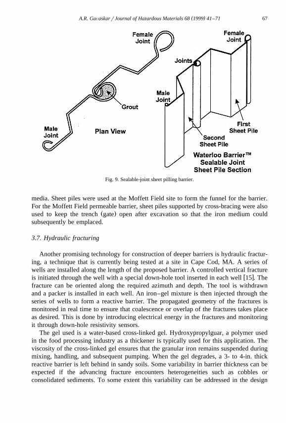
Barriers made of a series of steel sheet piles driven into the ground have been used inthe construction industry for retaining soil. In order to adapt this technique forremediation applications, where both soil and water movement have to be restricted, theUniversity of Waterloo, Ontario has patented a technique for sealing adjoining sheetpiles by pouring grout into the joints. Fig. 9 shows cross-sections of a sealable-jointsheet pile barrier. Sheet pile barrier integrity can be maintained to depths of about 50 ft.Beyond this depth, the sheet piles can be driven in, but it is unclear how well theintegrity of the sealed joints is maintained. About 40- to 45-ft. long sheet piles can beeasily transported to the site. Beyond this length, sheet piles have to transported insections to the site, and then welded together during installation.
Sheet pile barriers can be installed relatively quickly at most sites. They areespecially useful when the barrier has to be installed under horizontal space limitations.Because sheet piles are relatively thin and can be driven straight down, this type ofbarrier was used at the Dover site for the funnel sections because of the proximity of thefunnel walls to subsurface utility lines and a road that had to stay open duringconstruction. In fact one of the utility lines was cut and rejoined over the sheet pile wallafter the barrier was completed. A 100-ft. crane with a vibratory hammer was used todrive the sheet piles 45 ft. into the ground with a 2-ft. key in the aquitard. Anotherreason for choosing a sheet pile barrier instead of slurry wall at the Dover site wasbecause the sheet pile barrier generates much less spoils. Sheet piles are also useful asdividers when the reactive cell or gate has to be divided into sections to house different
( )A.R. GaÕaskarrJournal of Hazardous Materials 68 1999 41–71 67
Fig. 9. Sealable-joint sheet pilling barrier.
media. Sheet piles were used at the Moffett Field site to form the funnel for the barrier.For the Moffett Field permeable barrier, sheet piles supported by cross-bracing were also
Ž .used to keep the trench gate open after excavation so that the iron medium couldsubsequently be emplaced.
3.7. Hydraulic fracturing
Another promising technology for construction of deeper barriers is hydraulic fractur-ing, a technique that is currently being tested at a site in Cape Cod, MA. A series ofwells are installed along the length of the proposed barrier. A controlled vertical fracture
w xis initiated through the well with a special down-hole tool inserted in each well 15 . Thefracture can be oriented along the required azimuth and depth. The tool is withdrawnand a packer is installed in each well. An iron–gel mixture is then injected through theseries of wells to form a reactive barrier. The propagated geometry of the fractures ismonitored in real time to ensure that coalescence or overlap of the fractures takes placeas desired. This is done by introducing electrical energy in the fractures and monitoringit through down-hole resistivity sensors.
The gel used is a water-based cross-linked gel. Hydroxypropylguar, a polymer usedin the food processing industry as a thickener is typically used for this application. Theviscosity of the cross-linked gel ensures that the granular iron remains suspended duringmixing, handling, and subsequent pumping. When the gel degrades, a 3- to 4-in. thickreactive barrier is left behind in sandy soils. Some variability in barrier thickness can beexpected if the advancing fracture encounters heterogeneities such as cobbles orconsolidated sediments. To some extent this variability can be addressed in the design

( )A.R. GaÕaskarrJournal of Hazardous Materials 68 1999 41–7168
by injecting a slurry that provides a barrier thickness greater than the minimum requiredfor treatment. Until more field experience is obtained with this technique, at least two
w xparallel fracture reactive barriers may be considered 16 .Ž .This technique may also be used for installation of an impermeable barrier funnel
by injecting a soil–bentonite slurry instead of an iron–gel mixture.
3.8. Vibrating beam
In this technique, an H-beam or mandrel with a sacrificial shoe at the bottom is used.The beam is driven into the ground with a vibratory hammer creating a void. As thebeam is raised, grout is injected into the void through special nozzles at the bottom ofthe beam. An impermeable barrier is thus installed by driving at overlapping intervals.
This technique is currently being tested at a site in Florida to see if it can be used tow xinstall a permeable reactive barrier 17 . In the first test, dry iron was installed in the
void through a hollow mandrel driven with a vibratory hammer. The mandrel was usedto create a 4-in. thick, 32-in. long void down to 45-ft. depth with each entry. A total of32 overlapping panels were installed. No spoils were generated. In the second test, a36-in. I-beam with a highrlow pressure nozzle was driven into the ground. Water wassprayed through the high pressure side of the nozzle to help create the void. Aniron–guar gum slurry was introduced into the void through the low-pressure side of thenozzle as the beam was brought up. During the installation of 24 panels, approximately24 tons of soil and 4000 gal of liquid were generated.
3.9. Jetting
Jet grouting has been used for infrastructure development in Japan and Europe sincethe 1970s. The technique is being increasingly used in the US for reducing thepermeability of soils for infrastructure development and impermeable barrier placementfor remediation. More recently, there has been some interest in substituting the groutwith an iron–guar gum slurry to install a permeable reactive barrier at deeper sites. A
w xfield demonstration of this technique is underway at Dover, DE 18 .Jet grouting involves the injection of grout at high pressures into the ground. The
high velocity jet erodes the soil and replaces, some or all of it, with grout. Jet groutingsystems are classified into three types depending on the delivery mechanism. In a singlerod system, the fluid injected is grout. In a double-rod system, grout and compressed airare injected. The combined effect of the high-pressure grout and air results in a greaterpercentage of soil being removed and replaced with grout. The remaining soil–groutmixture is called soilcrete. In a triple rod system, grout, air, and water are jetted. Thistriple combination enables an even higher percentage of soil to be removed, and thesystem can be used for almost complete replacement of the soil with grout. The triplerod system offers better control over injection rates and results in better quality ofsoilcrete. While the single and double rod systems can be used in loose sandy soils, thetriple rod system can be used in most types of soil.
If the injection rod is rotated as it is brought up, a column of soilcrete can beinstalled. A continuous impermeable barrier can be created by installing a row, or
( )A.R. GaÕaskarrJournal of Hazardous Materials 68 1999 41–71 69
multiple rows, of overlapping columns. Alternatively, a thin panel of soilcrete can beinstalled by not rotating the rod. A continuous barrier, sometimes referred to as a thindiaphragm wall, is formed by installing a row of overlapping panels.
It is the triple rod system that is projected as being suitable for installing permeablereactive barriers. Grout can be used to install impermeable sections or funnel. A slurrymade of granular iron and guar gum is used to install the reactive section.
3.10. Deep soil mixing
This is a technique that has been used for in situ stabilization of soils and has beenproposed for permeable barrier application. A device with three large augers is used to
Ž . Ž .mix grout impermeable barrier or iron slurry permeable barrier with subsurface soil.Depths of 120 ft. are claimed to be possible with this technique.
3.11. Construction quality control
Because a barrier works by changing the hydraulic conductivity of a targeted aquiferregion, it is important to ensure that this objective is being achieved. In the case of the
Ž .permeable reactive sections of the barrier, the key is to ensure that a the requiredŽhydraulic conductivity which is usually designed to be higher than that of the
. Ž .surrounding aquifer is being achieved, and b that the reactive medium is continuouslyand uniformly distributed in the installed reactive cell zone. In the case of impermeable
Ž . Ž .sections funnel , the key is to ensure that a the designed reduction in conductivity isŽ .being achieved, and b that this lower conductivity zone is continuous and uniform.
These objectives can be achieved through quality control steps undertaken during thepre-installation, installation, and post installation phases. For both permeable andimpermeable sections, quality control also improves the longevity of the barrier.
Examples of quality control issues that can be addressed in the pre-installation phaseare as follows.
Ø In the case of slurry wall, the soil–bentonite slurry mix can be tested for chemicalcompatibility with the site groundwater. If a cement–bentonite slurry is used, this test isnot as critical and a conservative mix can be designed.
Ø Mapping the detailed hydrogeologic characteristics of the site in the immediatevicinity of the planned barrier.
Examples of quality control issues that can be addressed in the installation phase areas follows.
Ø Ensuring that the reactive medium is packed properly in the reactive cell. In atrench-type installation, workers would actually enter the trench to physically press thegranular iron into place with each 1-ft. layer of medium installed. However, safety issuesassociated with confined space entry could dictate the use of other remote means ofdoing this.
Ø In a funnel-and gate type system, it is important to obtain a good seal between theŽ .impermeable and permeable sections. At the Dover site see Fig. 7b , steel sheets with
an interlock were installed on either side of the reactive cell. The male joint of the first

( )A.R. GaÕaskarrJournal of Hazardous Materials 68 1999 41–7170
sheet pile of the funnel on either side was driven through this interlock and the joint wasgrouted.
Examples of quality control issues that can be addressed in the post-installation phaseare as follows.
Ø Performance monitoring that goes beyond just compliance issues. For example,measuring the redox potential at various points along the flowpath through the reactivemedium can give a good indication of the uniformity and continuity of the reactivemedium.
Ø Individual construction techniques often have their own special quality evaluationtechniques associated with them. For example, for installation by hydraulic fracturingthe developers have adapted a technique of electrical resistivity measurements toevaluate the geometric distribution and continuity of fractures.
4. Discussion
An optimal design for a permeable reactive barrier can be achieved by a comprehen-sive examination of the site that includes reaction rates of the contaminants and the sitehydrogeology. Depth of the installation is the main factor that drives the selection of aconstruction technique for permeable barriers. A geochemical evaluation based on theinorganic constituents of the aquifer and long-term monitoring of the barrier can be doneto evaluate the longevity of the barrier.
Acknowledgements
The author would like to acknowledge the US Air Force representatives, Lt. DennisO’Sullivan and Greg Jackson, who provided site access and guidance for the Dover AirForce Base Permeable Barrier Project. Charles Reeter and Steve Chao from the USNavy provided site access and guidance for the Moffett Field barrier site. John Vogan ofEnvironmetal Technologies, Inc., provided additional technical guidance during theimplementation of these projects.
References
w x1 R.W. Gillham, S.F. O’Hannesin, Enhanced degradation of halogenated aliphatics by zero-valent iron,Ž .Ground Water 32 1994 958–967.
w x2 T.M. Sivavec, D.P. Horney, Reductive dechlorination of chlorinated ethenes by iron metal, Preprints ofthe Papers Presented at the 209th ACS National Meeting, Anaheim, CA, April 2–6, 1995, pp. 695–698.
w x3 A.R. Gavaskar, N. Gupta, B.M. Sass, R.J. Janosy, D. O’Sullivan, Permeable Barriers for GroundwaterRemediation; Design Construction and Monitoring, Battelle Press, Columbus, OH, 1998, 176 pp.
w x4 A.L. Roberts, L.A. Totten, W.A. Arnold, D.R. Burris, T.J. Campbell, Reductive elimination of chlori-Ž . Ž .nated ethylenes by zero-valent metals, Environ. Sci. Technol. 30 9 1996 2654–2659.
w x5 D.R. Burris, T.J. Campbell, V.S. Manoranjan, Sorption of trichloroethylene and tetrachloroethylene in aŽ . Ž .batch reactive metallic iron–water system, Environ. Sci. Technol. 29 11 1995 2850–2855.
( )A.R. GaÕaskarrJournal of Hazardous Materials 68 1999 41–71 71
w x6 R.W. Gillham, S.F. O’Hannesin, Metal-catalyzed abiotic degradation of halogenated organic compounds,Proceedings of the IAH Conference: Modern Trends in Hydrogeology at Hamilton, Ontario, May 10–13,1992, pp. 94–103.
w x 07 W.S. Orth, R.W. Gillham, Dechlorination of trichloroethylene in aqueous solution using Fe , Environ.Ž . Ž .Sci. Technol. 30 1 1996 66–71.
w x8 US Environmental Protection Agency, Selection of media for the Dover AFB Field demonstration ofpermeable barriers to treat groundwater contaminated with chlorinated solvents, Preliminary Report to USAir Force for SERDP Project 107, August 4, 1997.
w x9 P.M. Jeffers, L.M. Ward, L.M. Woytowitch, N.L. Wolfe, Homogeneous hydrolysis rate constants forŽ . Ž .selected chlorinated methanes, ethanes, ethenes, and propanes, Environ. Sci. Technol. 23 8 1989
965–969.w x10 EnviroMetal Technologies, Personal communication from John Vogan, EnviroMetal Technologies,
Guelph, Ontario, January 1997.w x11 A.R. Gavaskar, B.M. Sass, E. Drescher, L. Cumming, D. Giammar, N. Gupta, Enhancing the reactivity of
permeable barrier media, Proceedings of the First International Conference on Remediation of Chlori-nated and Recalcitrant Compounds, at Monterey, CA, Vol. C1–6, May 18–21, 1998, pp. 91–96.
w x12 D.W. Blowes, R.W. Puls, T.A. Bennett, R.W. Gillham, C.J. Hanton-Fong, C.J. Ptacek, In-situ porousŽ .reactive wall for treatment of Cr VI and trichloroethylene in groundwater, Proceedings of the Interna-
tional Containment Technology Conference, St. Petersburg, FL, February 9–12, 1997, pp. 851–857.w x13 J.R. Romer, Installation of a reactive iron permeable barrier using continuous trenching, Presentation
Materials for the RTDF Permeable Reactive Barriers Action Team Meeting, Beaverton, OR, April 15–16,1998, pp. 39–40.
w x14 C.L. Yamane, S.D. Warner, J.D. Gallinatti, F.S. Szerdy, T.A. Delfino, D.A. Hankins, J.L. Vogan,Installation of a subsurface groundwater treatment wall composed of granular zero-valent iron, Preprint ofPapers Presented at the 209th ACS National Meeting, Anaheim, CA, Vol. 35, No. 1, April 2–7, 1995.
w x15 G. Hocking, S.L. Wells, R.I. Ospina, Design and construction of vertical hydraulic fracture placed ironreactive walls, Proceedings of the First International Conference on Remediation of Chlorinated andRecalcitrant Compounds, at Monterey, CA, Vol. C1–6, May 18–21, 1998, pp. 103–108.
w x16 D.W. Hubble, R.W. Gillham, J.A. Cherry, Emplacement of zero-valent metal for remediation of deepcontaminant plumes, Proceedings of the International Containment Technology Conference, St. Peters-burg, FL, February 9–12, 1997, pp. 872–878.
w x17 E.G. Marchand, P.A. Shirley, K.A. McNelis, T.L. Fiorillo, New installation techniques in side-by-sidedemonstrations at Cape Canaveral Air Station, Presentation Materials for the RTDF Permeable ReactiveBarriers Action Team Meeting, Beaverton, OR, April 15–16, 1998, pp. 23–24.
w x18 R. Landis, Potential use of jetting to emplace permeable reactive barriers, Presentation Materials for theRTDF Permeable Reactive Barriers Action Team Meeting, Beaverton, OR, April 15–16, 1998, p. 51.