permeable reactive barriers for inorganic and · pdf filepermeable reactive barriers for...
TRANSCRIPT
Permeable Reactive Barriers for Inorganic and Radionuclide
Contamination
August 2005
Prepared by
Kate Bronstein National Network of Environmental Management Studies Fellow
for
U.S. Environmental Protection Agency Office of Solid Waste and Emergency Response
Office of Superfund Remediation and Technology Innovation Washington, DC
www.epa.gov http://www.clu-in.org
Permeable Reactive Barriers for Inorganic and Radionuclide Contamination
NOTICE
This document was prepared by a National Network of Environmental Management Studies grantee under a fellowship from the U.S. Environmental Protection Agency. This report was not subject to EPA peer review or technical review. EPA makes no warranties, expressed or implied, including without limitation, warranties for completeness, accuracy, usefulness of the information, merchantability, or fitness for a particular purpose. Moreover, the listing of any technology, corporation, company, person, or facility in this report does not constitute endorsement, approval, or recommendation by EPA.
The report contains information gathered from a range of currently available sources, including project documents, reports, periodicals, Internet searches, and personal communication with involved parties. No attempts were made to independently confirm the resources used. It has been reproduced to help provide federal agencies, states, consulting engineering firms, private industries, and technology developers with information on the current status of this project.
About the National Network for Environmental Management Studies The National Network for Environmental Management Studies (NNEMS) is a comprehensive fellowship program managed by EPA’s Office of Environmental Education. The purpose of the NNEMS Program is to provide students with practical research opportunities and experiences.
Each participating headquarters or regional office develops and sponsors projects for student research. The projects are narrow in scope to allow the student to complete the research by working full-time during the summer or part-time during the school year. Research fellowships are available in environmental policy, regulations, and law; environmental management and administration; environmental science; public relations and communications; and computer programming and development.
NNEMS fellows receive a stipend at a level determined by the student’s level of education, the duration of the research project, and the location of the research project. Fellowships are offered to undergraduate and graduate students. Students must meet certain eligibility criteria.
ii
Permeable Reactive Barriers for Inorganic and Radionuclide Contamination
TABLE OF CONTENTS
PURPOSE ....................................................................................................................................... 1
1.0 INTRODUCTION..................................................................................................................... 1
1.1 Conventional Techniques...................................................................................................... 1 1.2 Permeable Reactive Barriers ................................................................................................. 21.3 Types of Reactive Media....................................................................................................... 4 1.4 Reactive Processes ................................................................................................................ 5
1.4.1 Abiotic Reduction-Oxidation ......................................................................................... 5 1.4.2 Biotic Reduction-Oxidation ........................................................................................... 5 1.4.3 Chemical Precipitation ................................................................................................... 6 1.4.4 Sorption and Ion Exchange ............................................................................................ 6
1.5 Site Characterization ............................................................................................................. 7 1.5.1 Hydrogeology................................................................................................................. 8 1.5.2 Contaminant Distribution............................................................................................... 9 1.5.3 Geochemistry ................................................................................................................. 9 1.5.4 Microbiology................................................................................................................ 10
1.6 PRB Configurations ............................................................................................................ 10
2.0 NATURE OF CONTAMINATION ....................................................................................... 11
2.1 Inorganic Contamination..................................................................................................... 11 2.2 Radionuclides ...................................................................................................................... 11
3.0 CASE STUDIES ..................................................................................................................... 11
3.1 Case Studies: Inorganics ..................................................................................................... 12 3.1.1 100 D Area, Hanford Site, Benton County, Washington ............................................. 12 3.1.2 Coeur d’Alene Mining District (Success Mine and Mill), Wallace, Idaho.................. 13 3.1.3 Conestoga-Rovers & Associates (CRA), Niagara Falls, New York ............................ 15 3.1.4 Cyprus AMAX Minerals Company/AMAX Realty Development Inc., Carteret, NJ.. 16 3.1.5 DuPont Site, East Chicago ........................................................................................... 16 3.1.6 E.I. DuPont, Newport Superfund Site, Delaware......................................................... 17 3.1.7 Frontier Hard Chrome (FHC) site, Vancouver, Washington ....................................... 19 3.1.8 Haardkrom Site, Kolding, Denmark ............................................................................ 21 3.1.9 Nickel Rim Mine Site, Sudbury, Ontario, Canada ....................................................... 22 3.1.10 Savannah River Site TNX Area, Aiken, South Carolina ........................................... 23 3.1.11 Tonolli Superfund Site, Nesquehoning, Pennsylvania............................................... 24 3.1.12 Universal Forest Products, Inc., Granger, Indiana ..................................................... 25 3.1.13 U.S. Coast Guard Support Center, Elizabeth City, NC.............................................. 26 3.1.14 Vancouver Site, Acid Mine Drainage ........................................................................ 26 3.1.15 Wheel Jane Tin Mine, Cornwall, UK......................................................................... 27 3.1.16 Zenaca Ag Products/Campus Bay, Richmond, California......................................... 28
3.2 Case Studies: Radionuclides ............................................................................................... 28 3.2.1 Bodo Canyon Disposal Site, La Plata County, Colorado............................................. 28 3.2.2 Chalk River Laboratories, Ontario, Canada ................................................................. 30 3.2.3 Cotter Corporation Uranium Mill, Cañon City, Colorado ........................................... 31
iii
Permeable Reactive Barriers for Inorganic and Radionuclide Contamination
3.2.4 Fry Canyon site, Fry Canyon, Utah ............................................................................. 32 3.2.5 Mecsek Ore, Pecs, Hungary ......................................................................................... 33 3.2.6 Monticello Mill Tailings site, Monticello, Utah .......................................................... 34 3.2.7 Mortandad Canyon, Los Alamos, New Mexico........................................................... 36 3.2.8 Rocky Flats Environmental Technology Site (Solar Ponds Plume), Golden, CO ....... 37 3.2.9 West Valley Demonstration Site, New York ............................................................... 38 3.2.10 Y-12 Site, Oak Ridge, Tennessee............................................................................... 39
4.0 UPCOMING RESEARCH...................................................................................................... 41
4.1 Injection to Treat Hexavalent Chromium (Cr(VI)) ............................................................. 41 4.2 Macalloy Corporation Site, Charleston, South Carolina..................................................... 41 4.3 East Helena Superfund Site, East Helena, Montana ........................................................... 42 4.4 Columbia Nitrogen Site, Charleston, South Carolina ......................................................... 43 4.5 Delatte Metals Site, Ponchatoula, Louisiana....................................................................... 43 4.6 Swine CAFO, Oklahoma..................................................................................................... 444.7 Lembach und Schleiera (former dye plant), Wiesbaden, Hesse, Germany......................... 44
5.0 LESSONS LEARNED............................................................................................................ 45
5.1 Site Characterization and PRB Design................................................................................ 45 5.2 Installation ........................................................................................................................... 46 5.3 Performance Monitoring ..................................................................................................... 46 5.4 Long-term Performance ...................................................................................................... 47
6.0 FUTURE DIRECTIONS OF PRB TECHNOLOGY.............................................................. 47
6.1 New Barrier Materials: Ligand-Based Active Materials..................................................... 47 6.2 Nanoscale ZVI for use within PRBs and for source treatment ........................................... 48 6.3 Phytoremediation as a Polishing Technique ....................................................................... 49 6.4 Electrokinetic Techniques ................................................................................................... 49
7.0 CONCLUSION ....................................................................................................................... 50
APPENDIX A. PRB SUMMARY TABLE .................................................................................. 52
REFERENCES.............................................................................................................................. 54
iv
Permeable Reactive Barriers for Inorganic and Radionuclide Contamination
PURPOSE
This paper is meant to be an updated reference for project managers, engineers, students, and others interested in a review of case studies of the instances where permeable reactive barriers have been used to remediate sites contaminated with inorganics and radionuclides. This paper mainly focuses on case studies, but a brief overview will be given on topics such as: treatment media types, reactive processes, site characterization, configuration, and the nature of contamination. The case studies are broken into two sections—inorganics and radionuclides— and are listed alphabetically within each section. They contain the most recent information available, as well as contact information for future updates. A section highlighting upcoming research followed by a lessons learned section and a section focusing on the future directions of PRB technology are also included at the end of the paper.
1.0 INTRODUCTION
Groundwater is the main source of available drinking water worldwide, but year after year, the consequences of human endeavors are jeopardizing its pristine quality. After an aquifer has become contaminated, it may be unsafe to drink and the contamination may migrate to other areas. It is, therefore, important to develop high-quality, yet cost-effective methods, to mitigate groundwater contamination problems.
A large number of National Priorities List (NPL) and Superfund sites have been contaminated by the direct result of the mining, milling, refining, and industrial uses of metals, coal, and petroleum, improper waste disposal, or accidents involving hazardous substances that have led to extensive areas of groundwater contamination with inorganic compounds of concern throughout the country. Acid mine drainage, a consequence of the mining industry, is the leading source of groundwater pollution with inorganic compounds of concern in many states. In one of these states, Pennsylvania, the estimated clean up cost related to acid mine drainage using traditional technologies is $15 billion dollars (PADEP). This is just one example highlighting the need for an economical cleanup methodology.
Much of the land impacted by inorganic and radionuclide contamination is rural and scarcely populated with low land valuation, but often with high ecological value. While the high price of cleanup is generally not considered cost effective in rural areas when measured against low land valuation, the potential damage to ecosystems and the environment must be considered in determining the need for remediation. In contrast, in densely populated areas, when untreated contamination migration affects non-replaceable or limited drinking water supplies, cleanup costs are less of a consideration compared to the need for rapid mitigation of the problem. In each of these situations, it is important to contain and remediate the area as efficiently and cost effectively as possible in order to reduce threats to human health and the surrounding ecosystem.
1.1 Conventional Techniques
The major traditional approach to addressing contaminated groundwater has been to remove it from the aquifer through extraction wells, send it to a water treatment plant, and then either reinject it into the ground or dispose of it off-site (Moyers et al., 1997). This type of treatment is
1
Permeable Reactive Barriers for Inorganic and Radionuclide Contamination
most commonly referred to as “pump-and-treat.” Occasionally, a contaminant source area can be isolated with low permeability barriers or covers to prevent contaminant migration, but the pollution remains on-site (Blowes et al., 2000).
There are many disadvantages to the pump-and-treat method, which have spurred an intensified search for replacement innovative technologies. Pump-and-treat techniques are expensive, have high energy requirements, carry the risk of exposure to contamination, and are unable to remove contaminants sorbed to the soil (IBC, 1999). For instance, the achievable extent of cleanup of dense or light non-aqueous phase liquids (NAPL) depends primarily upon the nature of the contaminant. Because NAPLs do not readily dissolve in water, they may desorb from the soils and contaminate the aquifer after the pump-and-treat approach has been stopped (Moyers et al., 1997). Naftz et al. (2002) agrees that the most difficult aspect of pump-and-treat remediation “is the efficient extraction of contaminants that are highly associated with the aquifer matrix.” Achieving a full remediation of an area through the use of pump-and-treat technologies is infrequent, resulting in the potential for additional costly cleanup options. Using pump-and-treat to remediate areas where heavy metals are slowly leaching from a source or where polycyclic aromatic hydrocarbons with low bioavailability are present has generally proven ineffective (Simon, 2000). Evidence has shown that permeable reactive barriers may be an enhanced alternative to treat contaminated groundwater because, when properly employed and operating effectively, they can decrease the risk caused by inorganics and radionuclides within groundwater through reduction-oxidation (redox) reactions, precipitation, and/or sorption of the contaminants to a reactive media.
1.2 Permeable Reactive Barriers
A permeable reactive barrier (PRB) is considered an innovative, green engineering approach used to remediate contaminated groundwater. It is a passive, in situ technology that has a high potential to treat shallow aquifers at a lower cost than traditional pump-and-treat methods, but due to a lack of long-term data, its cost-effectiveness has not been proven (Naftz et al., 2002; Roehl et al., 2005). However, Schad and Gratwohl (1998) have found that the remediation costs can be up to 50 percent less than pump-and-treat methods based on data collected at several sites. In addition, using PRBs reduces contaminant exposure to humans and allows the overlying land to be actively used during remediation.
A permeable reactive barrier, as defined by EPA, is
An emplacement of reactive media in the subsurface designed to intercept a contaminant plume, provide a flow path through the reactive media, and transform the contaminant(s) into environmentally acceptable forms to attain remediation concentration goals down-gradient of the barrier.
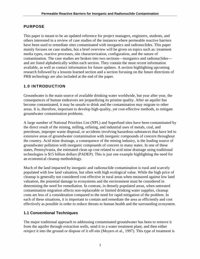
Groundwater flows through these permeable barriers by way of the natural gradient as the reactive media inside the wall traps and/or degrades the compounds of concern. This results in the absence or reduced concentration of these compounds in the groundwater downgradient of the wall. (USEPA, 2001b). The mobility, availability, and toxicity of contaminants also have been shown to decrease (Simon, 2000). Once a PRB has been installed, it remains there
2
Permeable Reactive Barriers for Inorganic and Radionuclide Contamination
indefinitely until the lifetime of the wall has been reached, or contamination has been degraded into less harmful components. Site closure needs, however, may require that the PRB be removed after desired contaminant levels have been achieved.
Figure 1: Permeable Reactive Barrier
Source: Powell & Associates 2005
The concept of the PRB was first developed by the University of Waterloo in the early 1990s. The first pilot-scale PRB was installed in 1991 at Borden, Ontario, to treat a plume of chlorinated solvents. The first full-scale commercial PRB was installed in 1994 at Sunnyvale, California, for chlorinated solvents as well, and since then, the use of PRBs has grown throughout the world as they have been shown to be an effective alternative to treat various organic and inorganic contaminants. (University of Waterloo, 2001). Table 1 shows several advantages and disadvantages associated with implementation of a PRB. Site specific problems do arise, but have not been included here.
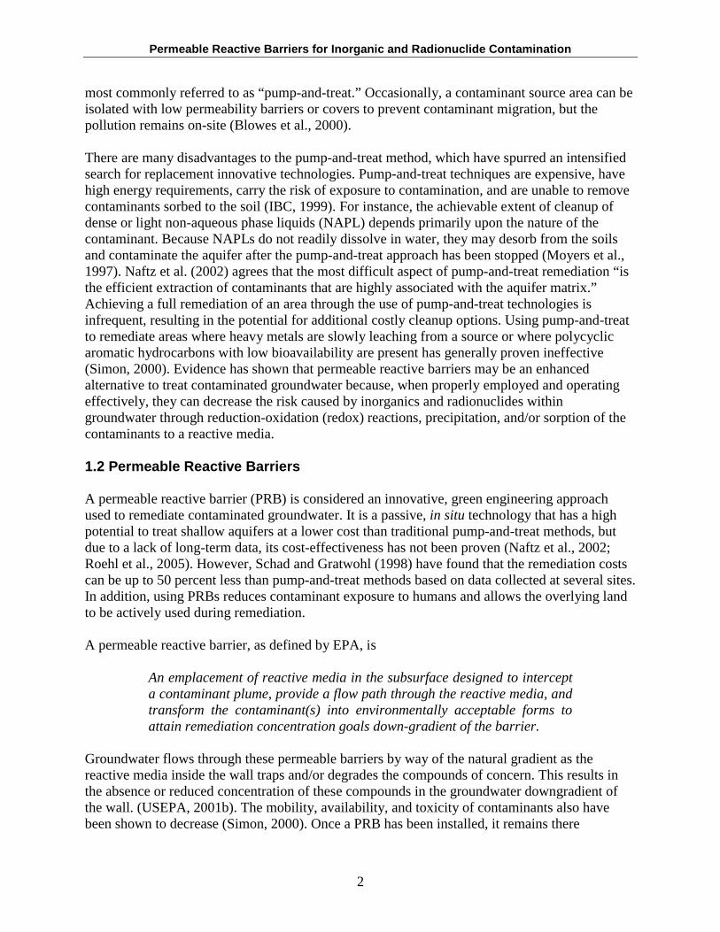
Table 1: PRB Advantages and Disadvantages Advantages Disadvantages
Able to treat a wide range of contaminants Large rocks, below ground structures may (organics, inorganics, radionuclides) present a problem during construction
Passive treatment systems Biofouling can reduce pore spaces, thereby reducing permeability
May cost less for cleanup Lengthy time for cleanup and monitoring
Reduced exposure to contaminants Site characterization is more complex
No loss of groundwater
Mounding: Occasionally when unusual rainfall events occur, or when reactivity/porosity of the barrier is significantly reduced, groundwater can back up on the upgradient side, and may choose alternate pathways around the barrier.
Relatively low maintenance and operational costs
Barriers may have performance lives lasting decades
Site is able to be in use while treatment is occurring
3
Permeable Reactive Barriers for Inorganic and Radionuclide Contamination
1.3 Types of Reactive Media
The characteristics used to determine the type of reactive media chosen are:
• Reactivity - The reaction rate and equilibrium constant of the contaminant with the reactive material are used to determine the required residence time, and therefore, the size of the PRB. The barrier must immobilize the contaminant within the reactive material in order to be effective.
• Stability - The reactive material needs to be active for a certain amount of time in order to reduce/eliminate contamination. Most importantly, the reactive material needs to persist in the subsurface environment for an extended period of time as secondary precipitates form, because once the PRB has been installed, it is labor-intensive and expensive to extract and replace the reactive medium.
• Availability and cost - The reactive material should be readily available and at a reasonable cost so as to implement a cost-effective remediation strategy.
• Hydraulic performance - The permeability of the reactive material needs to be equal to or greater than the aquifer permeability to minimize flow restrictions.
• Environmental compatibility - Reactive materials need to be well understood and similarly matched with the subsurface environment by sort and grain size in order to minimize changes in groundwater flow. Unwanted byproducts must not be created during reactions with the contamination plume.
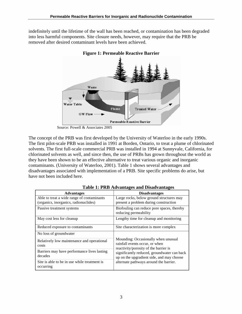
Suitable materials currently employed for use in a PRB are presented in Table 2. The type of reactive media chosen depends primarily on the nature of contamination present and the selective remediation approach. (Blowes et al., 2000; USEPA, 1998).
Table 2: Summary of Reactive Materials for Metals and Radionuclides Reactive Materials Geochemical Process Activated carbon Adsorption Amorphous Ferric Oxyhydroxide Adsorption Basic Oxygen Furnace Slag (BOFS) Sorption Ion exchange resins Adsorption Zero-Valent Iron Reduction and precipitation Limestone Precipitation Apatite Precipitation Sodium Dithionite Reduction & precipitation Sulfate Reducing Bacteria Microbial degradation Zeolites Adsorption Sand/Gravel beds + nutrients + oxygen Promotes microbial degradation
Source: Keller Ground Remediation; Roehl et al., 2005; USEPA, 1998.
4
Permeable Reactive Barriers for Inorganic and Radionuclide Contamination
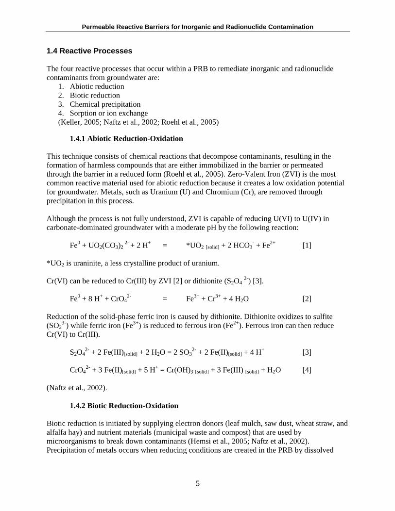
1.4 Reactive Processes
The four reactive processes that occur within a PRB to remediate inorganic and radionuclide contaminants from groundwater are:
1. Abiotic reduction 2. Biotic reduction 3. Chemical precipitation 4. Sorption or ion exchange(Keller, 2005; Naftz et al., 2002; Roehl et al., 2005)
1.4.1 Abiotic Reduction-Oxidation
This technique consists of chemical reactions that decompose contaminants, resulting in the formation of harmless compounds that are either immobilized in the barrier or permeated through the barrier in a reduced form (Roehl et al., 2005). Zero-Valent Iron (ZVI) is the most common reactive material used for abiotic reduction because it creates a low oxidation potential for groundwater. Metals, such as Uranium (U) and Chromium (Cr), are removed through precipitation in this process.
Although the process is not fully understood, ZVI is capable of reducing U(VI) to U(IV) in carbonate-dominated groundwater with a moderate pH by the following reaction:
Fe0 + UO2(CO3)2 2- + 2 H+ = *UO2 [solid] + 2 HCO3
- + Fe2+ [1]
*UO2 is uraninite, a less crystalline product of uranium.
Cr(VI) can be reduced to Cr(III) by ZVI [2] or dithionite (S2O4 2-) [3].
2Fe0 + 8 H+ + CrO4 = Fe3+ + Cr3+ + 4 H2O [2]
Reduction of the solid-phase ferric iron is caused by dithionite. Dithionite oxidizes to sulfite (SO2
3-) while ferric iron (Fe3+) is reduced to ferrous iron (Fe2+). Ferrous iron can then reduce Cr(VI) to Cr(III).
S2O42- + 2 Fe(III)[solid] + 2 H2O = 2 SO3
2- + 2 Fe(II)[solid] + 4 H+ [3]
CrO42- + 3 Fe(II)[solid] + 5 H+ = Cr(OH)3 [solid] + 3 Fe(III) [solid] + H2O [4]
(Naftz et al., 2002).
1.4.2 Biotic Reduction-Oxidation
Biotic reduction is initiated by supplying electron donors (leaf mulch, saw dust, wheat straw, and alfalfa hay) and nutrient materials (municipal waste and compost) that are used by microorganisms to break down contaminants (Hemsi et al., 2005; Naftz et al., 2002). Precipitation of metals occurs when reducing conditions are created in the PRB by dissolved
5
Permeable Reactive Barriers for Inorganic and Radionuclide Contamination
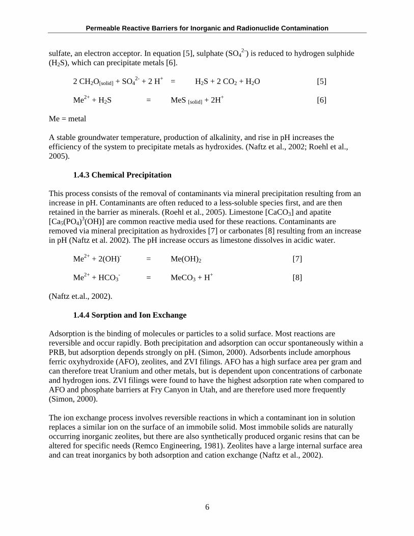
sulfate, an electron acceptor. In equation [5], sulphate (SO42-) is reduced to hydrogen sulphide
(H2S), which can precipitate metals [6].
2 CH2O[solid] + SO42- + 2 H+ = H2S + 2 CO2 + H2O [5]
Me2+ + H2S = MeS [solid] + 2H+ [6]
Me = metal
A stable groundwater temperature, production of alkalinity, and rise in pH increases the efficiency of the system to precipitate metals as hydroxides. (Naftz et al., 2002; Roehl et al., 2005).
1.4.3 Chemical Precipitation
This process consists of the removal of contaminants via mineral precipitation resulting from an increase in pH. Contaminants are often reduced to a less-soluble species first, and are then retained in the barrier as minerals. (Roehl et al., 2005). Limestone [CaCO3] and apatite [Ca5(PO4)
3(OH)] are common reactive media used for these reactions. Contaminants are removed via mineral precipitation as hydroxides [7] or carbonates [8] resulting from an increase in pH (Naftz et al. 2002). The pH increase occurs as limestone dissolves in acidic water.
Me2+ + 2(OH)- = Me(OH)2 [7]
Me2+ + HCO3 - = MeCO3 + H+ [8]
(Naftz et.al., 2002).
1.4.4 Sorption and Ion Exchange
Adsorption is the binding of molecules or particles to a solid surface. Most reactions are reversible and occur rapidly. Both precipitation and adsorption can occur spontaneously within a PRB, but adsorption depends strongly on pH. (Simon, 2000). Adsorbents include amorphous ferric oxyhydroxide (AFO), zeolites, and ZVI filings. AFO has a high surface area per gram and can therefore treat Uranium and other metals, but is dependent upon concentrations of carbonate and hydrogen ions. ZVI filings were found to have the highest adsorption rate when compared to AFO and phosphate barriers at Fry Canyon in Utah, and are therefore used more frequently (Simon, 2000).
The ion exchange process involves reversible reactions in which a contaminant ion in solution replaces a similar ion on the surface of an immobile solid. Most immobile solids are naturally occurring inorganic zeolites, but there are also synthetically produced organic resins that can be altered for specific needs (Remco Engineering, 1981). Zeolites have a large internal surface area and can treat inorganics by both adsorption and cation exchange (Naftz et al., 2002).
6
Permeable Reactive Barriers for Inorganic and Radionuclide Contamination
1.5 Site Characterization
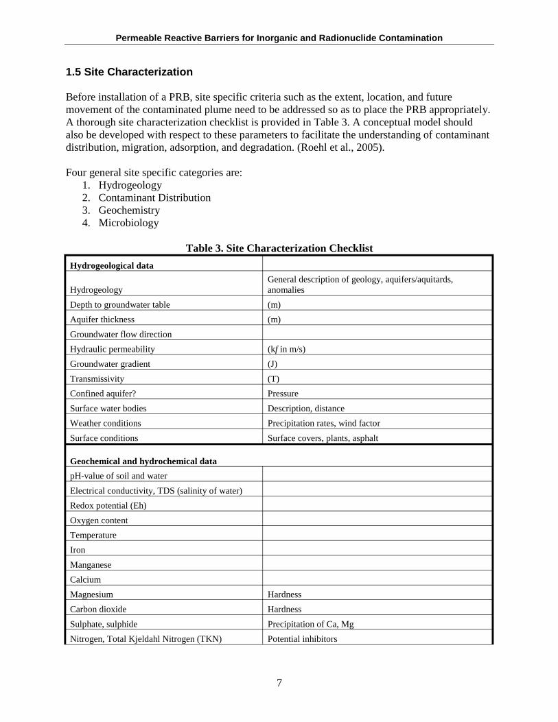
Before installation of a PRB, site specific criteria such as the extent, location, and future movement of the contaminated plume need to be addressed so as to place the PRB appropriately. A thorough site characterization checklist is provided in Table 3. A conceptual model should also be developed with respect to these parameters to facilitate the understanding of contaminant distribution, migration, adsorption, and degradation. (Roehl et al., 2005).
Four general site specific categories are: 1. Hydrogeology 2. Contaminant Distribution 3. Geochemistry 4. Microbiology
Table 3. Site Characterization Checklist
Hydrogeological data
General description of geology, aquifers/aquitards, Hydrogeology anomalies
Depth to groundwater table (m)
Aquifer thickness (m)
Groundwater flow direction
Hydraulic permeability (kf in m/s)
Groundwater gradient (J)
Transmissivity (T)
Confined aquifer? Pressure
Surface water bodies Description, distance
Weather conditions Precipitation rates, wind factor
Surface conditions Surface covers, plants, asphalt
Geochemical and hydrochemical data
pH-value of soil and water
Electrical conductivity, TDS (salinity of water)
Redox potential (Eh)
Oxygen content
Temperature
Iron
Manganese
Calcium
Magnesium Hardness
Carbon dioxide Hardness
Sulphate, sulphide Precipitation of Ca, Mg
Nitrogen, Total Kjeldahl Nitrogen (TKN) Potential inhibitors
7
Permeable Reactive Barriers for Inorganic and Radionuclide Contamination
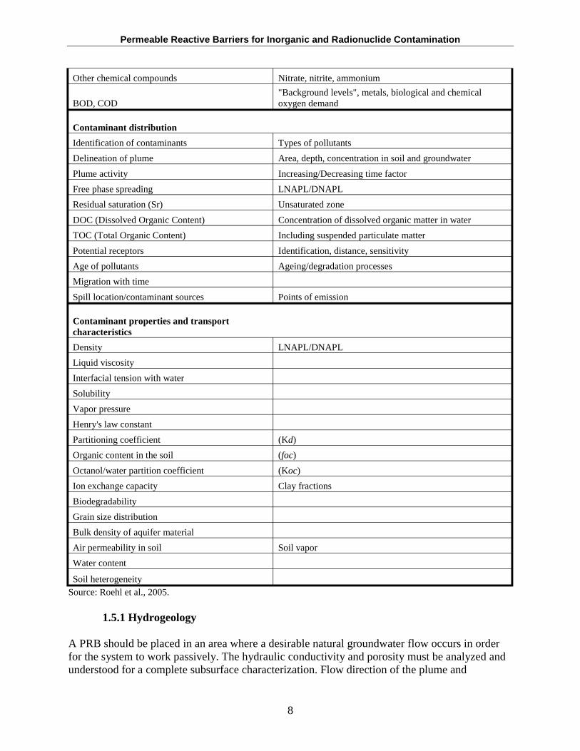
Other chemical compounds Nitrate, nitrite, ammonium
"Background levels", metals, biological and chemical BOD, COD oxygen demand
Contaminant distribution
Identification of contaminants Types of pollutants
Delineation of plume Area, depth, concentration in soil and groundwater
Plume activity Increasing/Decreasing time factor
Free phase spreading LNAPL/DNAPL
Residual saturation (Sr) Unsaturated zone
DOC (Dissolved Organic Content) Concentration of dissolved organic matter in water
TOC (Total Organic Content) Including suspended particulate matter
Potential receptors Identification, distance, sensitivity
Age of pollutants Ageing/degradation processes
Migration with time
Spill location/contaminant sources Points of emission
Contaminant properties and transport characteristics
Density LNAPL/DNAPL
Liquid viscosity
Interfacial tension with water
Solubility
Vapor pressure
Henry's law constant
Partitioning coefficient (Kd)
Organic content in the soil (foc)
Octanol/water partition coefficient (Koc)
Ion exchange capacity Clay fractions
Biodegradability
Grain size distribution
Bulk density of aquifer material
Air permeability in soil Soil vapor
Water content
Soil heterogeneity Source: Roehl et al., 2005.
1.5.1 Hydrogeology
A PRB should be placed in an area where a desirable natural groundwater flow occurs in order for the system to work passively. The hydraulic conductivity and porosity must be analyzed and understood for a complete subsurface characterization. Flow direction of the plume and
8
Permeable Reactive Barriers for Inorganic and Radionuclide Contamination
groundwater need to be determined for proper placement, and the PRB ideally should be keyed into an impermeable clay layer or bedrock to prevent contaminant underflow. Seasonal variations in water levels also must be taken into account, and the PRB must be designed accordingly so as to not have water flow over or around it. Gavaskar et al. (1998) states that barriers should be placed at least two feet above the water table. If the bedrock is fractured, the contaminant plume may be diverted around the PRB. Keying the PRB into the fractured bedrock may intercept these pathways. A hanging wall should be incorporated into the design if an impermeable layer is nonexistent. (Naftz et al., 2002; USEPA, 1998).
1.5.2 Contaminant Distribution
The location and extent (width, depth, length) of contamination must be thoroughly depicted so as to choose a suitable amount of reactive material. The PRB must be designed to treat the maximum contaminant load represented in the plume because it is difficult to add additional reactive material once the PRB is in place. (Roehl et al., 2005).
1.5.3 Geochemistry
Geochemistry is a branch of geology that focuses on the chemical composition of Earth’s materials. Geochemical measurements include pH, Eh, dissolved oxygen, carbonate alkalinity, and magnitude of species present that may affect precipitate formation.
pH is a log-scale from 0 to 14 that expresses the concentration of hydrogen ions. Many reactions are pH-dependent, and the ability to maintain a certain pH is sometimes necessary to achieve effective results.
Eh is a constituent’s redox potential measured in volts. A high Eh indicates a component’s susceptibility to reduction (i.e., gain electrons). A low Eh means that a component can be readily oxidized (i.e., lose electrons). A positive Eh value means that the reaction will occur spontaneously but, as the subsurface becomes anoxic, Eh values will decrease. (Nordstrom, 2000). Spontaneous reactions will lead to the desired reduction or oxidation of the contaminant, and consequently, a remediated effluent.
Dissolved oxygen refers to the amount of oxygen available for biochemical reactions in an aqueous solution. Dissolved oxygen is needed to support microbial life and is an indicator of water quality (Kentucky State).
Carbonate alkalinity is the acid-neutralizing capacity of water due to carbonate, or its ability to absorb H+ without significantly changing the pH (Monday Creek, 2001). This is significant when remediating acid-impacted waters. Neutralization may also promote microbiological growth, which can lead to consumption of contaminants of concern.
The species that may affect precipitate formation include: Ca, Fe, Mg, Mn, Al, Ba, Cl, F, CO32-,
SO42-. These species sometimes coat the reactive surface area, thereby decreasing reactivity and
lowering permeability by clogging pore spaces, which generally results in a shorter lifespan of the barrier. (USEPA,1998).
9
Permeable Reactive Barriers for Inorganic and Radionuclide Contamination
1.5.4 Microbiology
Recently, microbial populations living within PRBs have been shown to reduce contaminated plumes. One group of bacteria, sulfate reducing bacteria (SRB), are of particular importance in enhancing PRB technology’s ability to treat inorganic constituents. The SRBs are anaerobes that require a complete absence of oxygen, a reducing environment, and organic material in order to survive. They reduce sulfate to sulfide or hydrogen sulfide and are commonly used on sites where acid mine drainage is prevalent. SRBs promote precipitation of metals as insoluble metal sulfides. They require abundant sulfate and strict pH values. SRBs cannot directly metabolize complex organic substrates, and they may also produce toxic H2S gas (RMR, 2002).
1.6 PRB Configurations
Two traditional configurations of PRBs—continuous wall and funnel and gate—have been more commonly used, but other innovative designs include SRB PRBs, In Situ Redox Manipulation, and GeoSiphon/GeoFlow cells.
A continuous wall is a wall of reactive media that is placed in a shallow trench and is overextended vertically and horizontally to account for seasonal groundwater fluctuations. The width of the wall is determined by the required residence time and groundwater velocity. The wall must be keyed into an impermeable layer or bedrock to prevent contaminant underflow. It is often more expensive than funnel and gate installations due to the amount of reactive media used.
Funnel and gate systems consist of impermeable sides, such as sheet piling or slurry walls, that divert contaminated groundwater into a reactive gate. The velocity of the water within the gate is greater than the natural gradient and the funnel and gate must be designed to encompass this. The permeability of the gate must be equal to or greater than the aquifer permeability so that water does not back up and “overflow” around the funnel walls. The residence time in the gate must be sufficient to treat the contaminants at the same time. (USEPA, 1998).
In Situ Redox Manipulation (ISRM) is a newer approach to creating a reactive zone that reduces iron in aquifer sediments from Fe(III) to Fe(II). There are three phases of installation: injection, reaction, and withdrawal. Contaminated waters are replaced by one pore volume of the reagent solution to reduce soil permeability. The contaminated plume then flows through the zone by the natural gradient and is reduced by the injected material during the reaction phase. The distance that the liquid flows depends upon the viscosity of the fluid, rock permeability, and the injection pressure. The final phase is the withdrawal phase, where unreacted reagent, other reaction products, and mobilized trace metals are removed. This technique is said to provide a better residual recovery than any other PRB technique. (Naftz et al., 2002; Roehl et al., 2005).
GeoSiphon cells are similar to the funnel and gate concept, except that a siphon is used to increase groundwater flow. The upgradient edge of the siphon is placed in the contaminated plume while the downgradient end can be placed in the subsurface, a surface water body, or the ground surface. GeoSiphon cells work by connecting a large diameter well to a siphon, which accelerates the flow rate between points of a natural head difference. The system is still passive,
10
Permeable Reactive Barriers for Inorganic and Radionuclide Contamination
and the increased flow reduces instances of plugging due to mineral precipitates. The same types of reactive media can be used. (TechKnow, 2000).
2.0 NATURE OF CONTAMINATION
2.1 Inorganic Contamination
Inorganic contamination includes dissolved gases (O2, CO2, nitrogen, radon), metals, and negative ions (fluoride, chloride, nitrate, phosphate, sulfate, carbonate, and cyanide). Metals are required in small doses by organisms in order to perform certain catalytic functions, but the presence of excess metals are toxic and may cause internal damage depending on the length of exposure (Max-Planck Institut, 2000).
Unlike organics, inorganics cannot be broken down into harmless elements or compounds because many are already in elemental form; they can only be covered, buried, removed and recycled, moved to a safer location, or changed into another form through complexation with organics, new ligands, or speciation. Arsenic, lead, chromium, uranium, iron, nickel, zinc, and cadmium are common metals found in the groundwater at Superfund sites around the country. Some metals can undergo redox reactions to form solid precipitates with groundwater constituents, such as carbonate, sulfide, and hydroxide. Those that are not susceptible to redox reactions may be removed by precipitation, adsorption, or coprecipitation on mineral surfaces (USEPA, 1998).
Reaction rates vary greatly and depend on site-specific characteristics of the aquifer, groundwater, and reactive material. For this reason, reaction rates are often, and best, first determined within a laboratory setting. (USEPA, 1998).
The range of toxicity to human health is dependent upon the chemical form of the heavy metal. Certain natural forms of heavy metals have a lower toxicity, and can therefore be left on-site due to their low bioavailability, which may lead to a reduced cleanup cost. (ITRC, 1997).
2.2 Radionuclides
Radionuclides are atoms that emit radiation and are naturally found in some rocks and soils, but may also be man-made. Almost all elements that are heavier than bismuth, which has an atomic weight of 83, are unstable or radioactive. Common radionuclides found in contaminated groundwater include americium-241, cesium-137, iodine-129 and 131, plutonium, radium, radon, strontium-90, technetium-99, tritium, thorium, and uranium. Radionuclides tend to accumulate in human and animal bones and muscles, and may cause cancer and in extremely high doses, death. (Nanavut, 2005; USEPA, 2004b).
3.0 CASE STUDIES
The following case studies are pilot- and full-scale applications divided into two sections: inorganics and radionuclides. Each case study includes the most recent information available pertaining to the performance of the permeable reactive barrier.
11
Permeable Reactive Barriers for Inorganic and Radionuclide Contamination
3.1 Case Studies: Inorganics
3.1.1 100 D Area, Hanford Site, Benton County, Washington
Reactive Media: Sodium Dithionite Contaminants: Hexavalent Chromium Configuration: Injection Installation Date: 2003, full scale Cost: approximately $8,700,000
The Hanford Site was created in 1943 during World War II as part of the “Manhattan Project” to create plutonium for nuclear weapons, was operated until the 1980s, and then placed on the NPL list in July 1989. The 560 mi2 area was broken into four separate NPL sites: the 100 Area (26 mi2); 200 Area; 300 Area; and 1100 Area.
A large-scale In Situ Redox Manipulation (ISRM) method was successfully tested in 1997-98 to treat groundwater contaminated with hexavalent chromium (Cr(VI)). A plume was detected at depths of 15 to 90 m below ground surface (bgs). Sodium dithionite with a potassium carbonate/potassium bicarbonate buffer (pH 11) was injected into one well in 1997 and chromium concentrations were found to have decreased from 2 mg/L to 8 µ g/L. Injections were made into four other wells afterwards. The emplacement created a reduced zone approximately 150 ft long, perpendicular to groundwater flow, 30 ft wide, and 15 ft thick. Depth to groundwater is about 85 ft bgs. Average groundwater velocity is about 1 ft/day. Hydraulic conductivity measured 100 ft/day.
Dithionite reduces Fe(III) to Fe(II) by the following reaction:
S2O4 2-
(aq) + 2 Fe(III) (s) + 2 H2O = 2 SO3 2-
(aq) + 2 Fe(II) (s) + 4 H+
It is this reduced iron, Fe(II) that adsorbs to soil particles, creating a barrier. The sulfite is rapidly oxidized to sulfate, and the hydrogen ions are neutralized by the buffer. Redox-sensitive aqueous chromate reacts with Fe(II) and is precipitated as a solid hydroxide by:
CrO4 2-
(aq) + 3 Fe(II) (s) + 5 H+ = Cr(OH)3 (s) + 3 Fe(III) + H2O
(Naftz et al. 2002; Rai et al., 1989).
Performance monitoring was conducted through 1999, when a full-scale wall was installed in 2003. The full-scale ISRM is located 150 m from the banks and parallel to the Columbia River. It consists of 65 injection wells measuring 2,000 ft in length.
The maximum concentration of Cr(VI) was 4,000 µg/L. It takes the groundwater two years to travel from the barrier to the Columbia River, and sufficient time has not passed in order to fully assess the effect of the ISRM treatments. However, Cr(VI) concentrations are below the detection limit (8 µg/L) in 59 out of 66 wells. Cr(VI) concentrations are also declining in two monitoring wells 40 and 75 m downgradient of the barrier. Difficulty interpreting monitoring
12
Permeable Reactive Barriers for Inorganic and Radionuclide Contamination
well data arises due to the variability in groundwater flow rate and seasonal directional changes associated with the river.
There has been breakthrough of Cr(VI) in a number of wells within the barrier; specifically 9 out of the 65 have concentrations greater than the 100 ppb drinking water standard. An investigation is currently underway to correct the problem. Core samples from a degraded area of the barrier showed that the majority of the material had the same reductive capacity as when originally injected, while some thin pieces were prematurely oxidized. This indicates that the primary means controlling barrier degradation is linked with preferential flow in high permeability channels. “Tracer and dithionite injection tests and electromagnetic borehole flowmeter tests conducted at the site also indicate preferential flow within some wells.” Fruchter (2005) speculates that the high permeability channels may have been generated during the use of air-rotary drilling to emplace some of the injection wells in areas plagued with chromium breakthroughs.
Sources: Naftz et al., 2002; Personal Communication with John Fruchter 2005.
Contact Information: John Fruchter Batelle Pacific Northwest National Laboratory P.O. Box 999 (K6-96) Richland , WA 99352 Tel: 509-376-3937 Fax: 509-372-1704 Email: [email protected]
3.1.2 Coeur d’Alene Mining District (Success Mine and Mill), Wallace, Idaho
Reactive Media: Apatite II Contaminants: Lead (Pb), Cadmium (Cd), Zinc (Zn), Sulfate (SO4), Nitrate (NO3) Configuration: Compartment cells Installation Date: January 2001 Cost: Information not provided
The Coeur d’Alene mining district is located in Northern Idaho, where the 10-acre Success Mine and Mill site was the largest remaining metals loader in the Ninemile Creek drainage in 1995. Groundwater is contaminated from a Success Mine tailings/waste rock pile and is discharging into the East Fork of Ninemile Creek (EFNC). The tailings/waste rock pile is 1,200 ft long, 150 ft high, and has slopes of up to 40 degrees. EFNC joins the main portion of Ninemile Creek about 1.3 miles downstream from the Success site. The average annual flow of EFNC is 15.8 cfs, with peak flows occurring in April and May. Quartz monzonite bedrock is located 16.5 to 22.5 ft bgs.
The hydraulic conductivity of the alluvial aquifer (clean sand and gravel) averaged 1.7 x 10⁻³ ft/s, while that of the shallow bedrock (fractured igneous rock) averaged 5.6 x 10⁻⁵ ft/s. Groundwater flux is estimated to range from 3 and 101 gpm.
13
Permeable Reactive Barriers for Inorganic and Radionuclide Contamination
Phosphate-Induced Metal Stabilization using Apatite II was chosen as the method of cleanup because of its ability to stabilize a wide range of metals. Apatite minerals occur naturally, and sedimentary and biogenic apatites concentrate metals and radionuclides to millions of times the ambient concentration. Wright et al. (2004) found that apatite will lock in certain metals for up to a billion years with no occurrence of desorption, leaching, or exchange. Over 300 apatite minerals exist, but the apatite used at this site was composed of biogenically-precipitated material derived from fish bones. The specific composition is Ca10-x(PO4)6-x(CO3)x(OH)2, where x < 1. The reaction between the apatite and metals is very rapid and treatment is immediate. However, the grain size, flow rate, and barrier design will limit the reaction because they determine the rate at which the metals come in contact with the reactive media.
The 13.5 ft high, 15 ft wide, and 50 ft long PRB consisted of two cells that measure 8 ft high, 6.5 ft wide, and 45 ft long. The PRB vault was extended 2-3 ft above the spring groundwater high and keyed into the bedrock. A hydraulic drain was installed upgradient of the PRB just below the creek water level to direct any backed up groundwater towards the PRB, as well as to minimize surface water flow into the shallow groundwater. The inflow port of the PRB directs groundwater through two baffled PRB treatment cells and then out two outflow ports that discharge to the EFNC via a rock apron outfall. The head difference is 7.5 ft from inflow. Gravel overlies the East and West treatment cells. The West cell has 100% Apatite and the East has 50% Apatite, 50% gravel. About 108 yd3 of Apatite II was used.
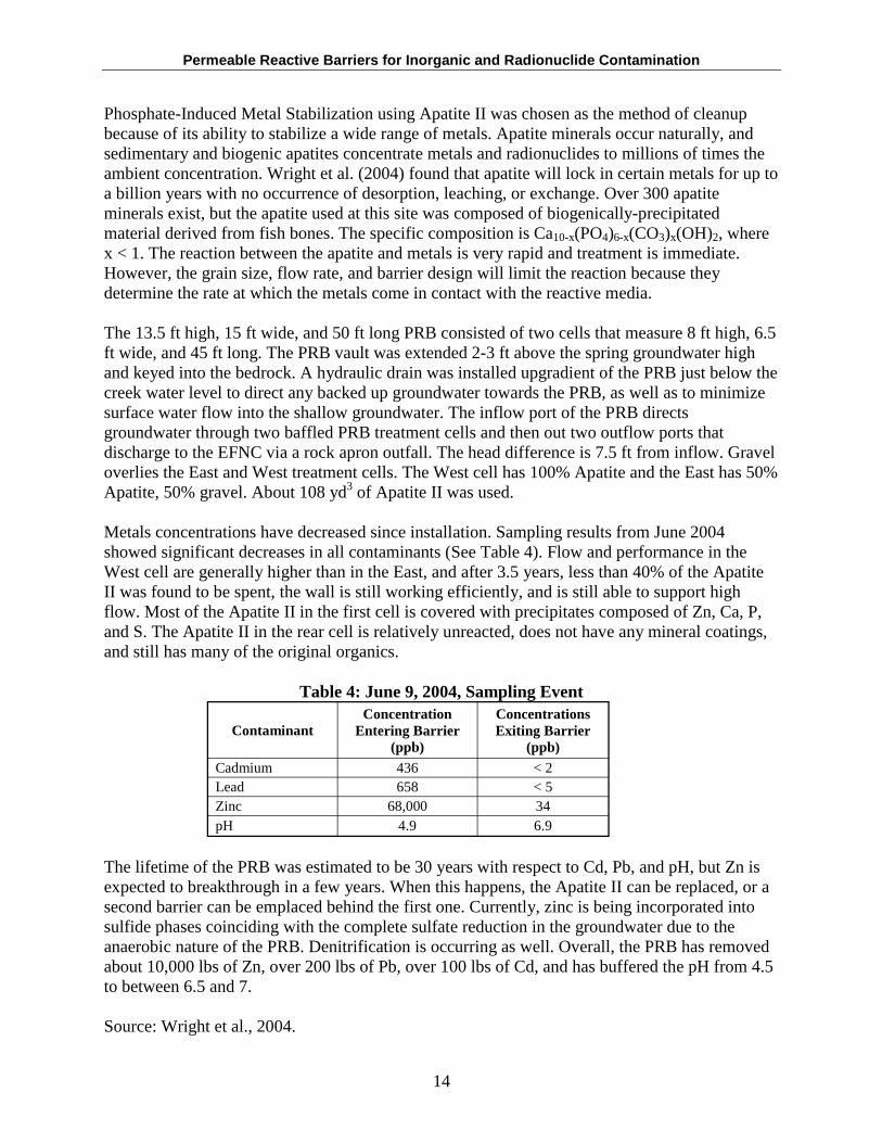
Metals concentrations have decreased since installation. Sampling results from June 2004 showed significant decreases in all contaminants (See Table 4). Flow and performance in the West cell are generally higher than in the East, and after 3.5 years, less than 40% of the Apatite II was found to be spent, the wall is still working efficiently, and is still able to support high flow. Most of the Apatite II in the first cell is covered with precipitates composed of Zn, Ca, P, and S. The Apatite II in the rear cell is relatively unreacted, does not have any mineral coatings, and still has many of the original organics.
Table 4: June 9, 2004, Sampling Event
Contaminant Concentration
Entering Barrier (ppb)
Concentrations Exiting Barrier
(ppb) Cadmium 436 < 2 Lead 658 < 5 Zinc 68,000 34 pH 4.9 6.9
The lifetime of the PRB was estimated to be 30 years with respect to Cd, Pb, and pH, but Zn is expected to breakthrough in a few years. When this happens, the Apatite II can be replaced, or a second barrier can be emplaced behind the first one. Currently, zinc is being incorporated into sulfide phases coinciding with the complete sulfate reduction in the groundwater due to the anaerobic nature of the PRB. Denitrification is occurring as well. Overall, the PRB has removed about 10,000 lbs of Zn, over 200 lbs of Pb, over 100 lbs of Cd, and has buffered the pH from 4.5 to between 6.5 and 7.
Source: Wright et al., 2004.
14
Permeable Reactive Barriers for Inorganic and Radionuclide Contamination
Contact Information: Judith Wright PIMS NW, Inc. 201 N. Edison Kennewick, WA 99336 Email: [email protected]
3.1.3 Conestoga-Rovers & Associates (CRA), Niagara Falls, New York
Reactive Media: Peat moss, compost, human hair, composted manure Contaminants: Mercury (Hg) Configuration: Permeable sacks anchored to a ditch Installation Date: 1999, pilot scale
Conestoga-Rovers & Associates (CRA) completed a study using humates to treat groundwater contaminated with Mercury (Hg) at a chemical manufacturing plant. Humates are naturally occurring complex organic materials that incorporate a high ion exchange capacity. Its ability to adsorb and detoxify metals makes it a suitable reactive medium. Hg can bind to a variety of sulphur-containing materials, hence peat moss, compost, human hair, and composted manure were chosen as test materials. Composted manure, the richest in humic substances, proved to be the most effective at removing soluble mercury from groundwater (99.8% removal) during batch and column laboratory studies.
A pilot-scale implementation of the technology was placed on the bank of a ditch where Hgcontaminated water discharges. Unlike other implementations, this one consisted of permeable sacks filled with a mixture of sand and compost anchored to the banks of the ditch to prevent the sacks from moving. Surface water in the ditch will flow through the sacks during periods of low-flow, and during high-flow, water will flow over the barrier. The sacks are predicted to adsorb dissolved Hg from the water for a period of three months before being replaced. The sacks are then dried and analyzed for proper disposal.
Source: CRA, 2000; Godage et al., 2000; Personal Communication with Alen Weston, Ph.D, August 15, 2005.
Contact Information: Alan Weston Director of Remedial Technology
Conestoga Rovers and Associates 2055 Niagara Falls Boulevard, Suite 3 Niagara Falls, NY 14304 Phone: 716-297-6150 Cell: 716-472-3411 Fax: 716-297-2265 Email: [email protected]
15
Permeable Reactive Barriers for Inorganic and Radionuclide Contamination
3.1.4 Cyprus AMAX Minerals Company/AMAX Realty Development Inc., Carteret, NJ
Reactive Media: Dolomitic limestone and powdered sodium carbonate Contaminants: Copper , Nickel, Zinc Configuration: Tank House Trench, full scale Installation Date: August 1993, extended in 2000
This former copper smelting facility has groundwater contaminated with heavy metals at average concentrations of 154 mg/L (Cu), 322 mg/L (Ni), 0.15 mg/L (Se), 8.9 mg/L (Zn). The groundwater is discharging into Arthur Kill, a nearby saline estuary. The water table is about 1015 ft bgs and bedrock is found at depths of 50-60 ft bgs. The trench installed in 1993 is 685 ft long by 45 ft deep with a width ranging from 3-5 ft. It was extended by 200 ft in 2000.
The trench was filled with 2,600 tons of dolomitic limestone and 20 tons of sodium carbonate. Flexible, slotted pipes were installed throughout the trench at eight locations to allow for the addition of powdered sodium bicarbonate as needed to aid in the remediation effects. Two PVC pipes were also placed within the trench to stimulate groundwater circulation and recharge of sodium carbonate solution.
Wells 4MD, 5M, 7M, and 7MD are all located downgradient of the trench. Nickel is the main contaminant of concern in 4MD, and throughout 2000 to December 2004, concentrations increased from 0.3 mg/L in June 2001, to 8.0 mg/L in June 2003, and then decreased to 4.8 mg/L in December 2004. Well 5M is downgradient of a chemical barrier constructed in 1994. Zinc concentrations in 5M increased from 0.64 mg/L in June 2004 to 1.1 mg/L in December 2004. Well 7M is also downgradient of the same chemical barrier, and selenium concentrations have slightly decreased from a high of about 2.5 mg/L in December 2003. Well 7MD is located in the same area as 7M and 5M, and zinc concentrations have varied greatly during monitoring, but the lowest concentration was found in the December 2004 sampling event. It is recommended that ongoing annual sampling be performed at each well.
Source: AMAX Realty Development, Inc., 2005.
Contact Information: Jeff Story Geologist
NJ Bureau of Ground Water Pollution Assessment Phone: 609-292-9964 Email: [email protected]
3.1.5 DuPont Site, East Chicago
Reactive Media: Basic Oxygen Furnace Slag (BOFS) Contaminants: Arsenic Configuration: Continuous Wall, full scale Installation Date: 2002
16
Permeable Reactive Barriers for Inorganic and Radionuclide Contamination
This was the first site to use basic oxygen furnace slag in a PRB to remediate arsenic-contaminated groundwater. BOFS is a nonmetallic waste byproduct created during steel production, and is particularly rich in iron and calcium oxyhydroxides. BOFS oxidizes As(III) to As(V), which will then sorb to the BOFS surface. Lab studies have shown a pH increase to as high as 12 when combined with water. Researchers from the University of Waterloo began using column tests with BOFS in the mid-90s to treat phosphorous, but it was not until 2002 that a BOFS PRB was installed at an industrial site for the treatment of Arsenic.
The As plume at this site ranges from between 5-27 ft bgs at concentrations below detection limit in the shallower depths to 1-3 ppm in the deeper areas. Two parallel PRBs composed of 100% BOFS were installed 15 ft apart. They each measure 2,000 ft long x 30 in. wide x 37 ft deep. The goal was to reduce As concentration to 10 ppb from initial concentrations of 1-3 ppm.
Unfortunately, the PRBs were installed beneath a waste/ash layer 5 ft bgs, and during a period of high groundwater level, some contamination may have migrated around and above the barriers. However, results have shown a decrease in the effluent from 1-3 ppm to <0.001 ppm. Long-term performance monitoring is occurring.
Source: Wilkens et al., 2003; ITRC, 2005; Smyth et al., 2005.
3.1.6 E.I. DuPont, Newport Superfund Site, Delaware
Reactive Media: Sand, Calcium sulfate, ZVI, and magnesium carbonate Contaminants: Maganese, Barium, Cadmium, Copper, Nickel, Lead, Zinc Configuration: Continuous Wall, pilot scale Installation Date: 2002 Cost: approximately $4 million
This site is located in Newport, DE, and is currently operated by a paint pigment production facility, a chromium dioxide production facility, two industrial landfills, and a baseball diamond. Groundwater samples taken in the late 1970s and early 1980s showed a significant amount of metals (barium, cadmium, cobalt, lead, manganese, nickel, and zinc) and volatile organic compounds (trichloroethylene and tetrachloroethylene) contamination. The site was added to the NPL in February 1990.
After conducting batch scale studies, John Wilkens of DuPont Central Research and Development, found that a mixture of sand, calcium sulfate (to remove barium), ZVI (to sorb zinc), and magnesium carbonate (to remove manganese) as the reactive material in the PRB would decrease concentrations of zinc, manganese, and barium. The components, Sand: CaSO4: ZVI: MgCO3, have a ratio of 100: 20: 5: 5.
A field demonstration PRB that is 2,200 ft long x 18 in. wide x 20 ft deep was installed in 2002. The three main contaminants, zinc, barium and manganese, among others, have been reduced to below standards. The success of the field study led the U.S. EPA to change the previous treatment technology from chemical precipitation involving sodium sulfate and sodium sulfide to
17
Permeable Reactive Barriers for Inorganic and Radionuclide Contamination
a treatment technology using a PRB, a low permeability groundwater barrier, and a landfill cap. This option eliminated the need to pump-and-treat any groundwater.
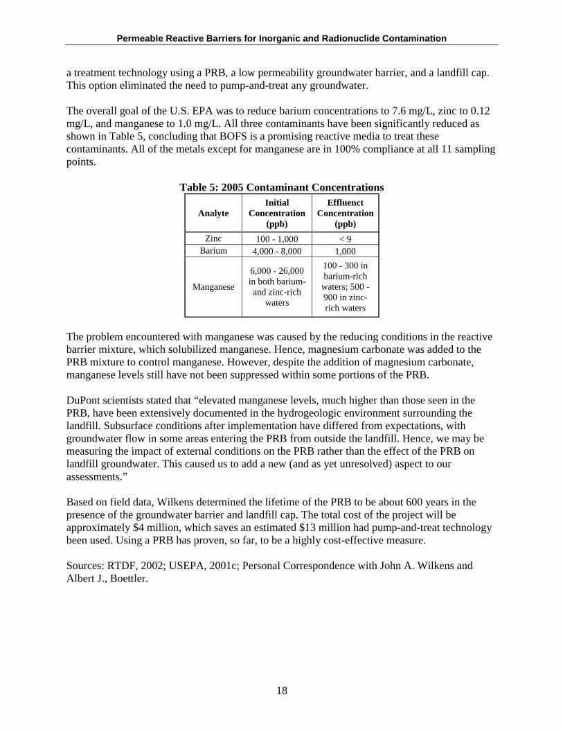
The overall goal of the U.S. EPA was to reduce barium concentrations to 7.6 mg/L, zinc to 0.12 mg/L, and manganese to 1.0 mg/L. All three contaminants have been significantly reduced as shown in Table 5, concluding that BOFS is a promising reactive media to treat these contaminants. All of the metals except for manganese are in 100% compliance at all 11 sampling points.
Table 5: 2005 Contaminant Concentrations
Analyte Initial
Concentration (ppb)
Effluenct Concentration
(ppb)
Zinc 100 - 1,000 < 9 Barium 4,000 - 8,000 1,000
Manganese
6,000 - 26,000 in both barium-and zinc-rich
waters
100 - 300 in barium-rich
waters; 500 900 in zinc-rich waters
The problem encountered with manganese was caused by the reducing conditions in the reactive barrier mixture, which solubilized manganese. Hence, magnesium carbonate was added to the PRB mixture to control manganese. However, despite the addition of magnesium carbonate, manganese levels still have not been suppressed within some portions of the PRB.
DuPont scientists stated that “elevated manganese levels, much higher than those seen in the PRB, have been extensively documented in the hydrogeologic environment surrounding the landfill. Subsurface conditions after implementation have differed from expectations, with groundwater flow in some areas entering the PRB from outside the landfill. Hence, we may be measuring the impact of external conditions on the PRB rather than the effect of the PRB on landfill groundwater. This caused us to add a new (and as yet unresolved) aspect to our assessments.”
Based on field data, Wilkens determined the lifetime of the PRB to be about 600 years in the presence of the groundwater barrier and landfill cap. The total cost of the project will be approximately $4 million, which saves an estimated $13 million had pump-and-treat technology been used. Using a PRB has proven, so far, to be a highly cost-effective measure.
Sources: RTDF, 2002; USEPA, 2001c; Personal Correspondence with John A. Wilkens and Albert J., Boettler.
18
Permeable Reactive Barriers for Inorganic and Radionuclide Contamination
Contact Information: John Wilkens DuPont Central Research and Development Email: [email protected]
Albert J. Boettler DuPont Central Research and Development Email: [email protected]
3.1.7 Frontier Hard Chrome (FHC) site, Vancouver, Washington
Reactive Media: Sodium dithionite Contaminants: Hexavalent Chromium (Cr(VI)) Configuration: ISRM, pilot scale Installation Date: May through early August 2003 Cost: Information not available
FHC is located in Vancouver, the southwestern portion of Washington State, about ½ mile north of the Columbia River. The ½-mile site was formerly operated as a chrome plating facility between 1958 and 1982, but FHC only operated there between 1970 and 1982. FHC disposed of wastewaters containing hexavalent chromium directly into an onsite dry well, resulting in groundwater contamination with chromium concentrations at nearly twice the state groundwater limit of 50 µg/L. In September 1993, the site was placed on the NPL list.
In June 2001, ISRM was selected as a remedy to reduce hexavalent chromium to trivalent chromium. An ISRM barrier provides long-term protection of groundwater, should any residuals occur, and efficient treatment of all soils and groundwater in the treatment area. As dissolved hexavalent chromium (in the form of a highly soluble and mobile chromate anion, CrO42) enters the reducing environment, it reacts with ferrous iron and is reduced to the trivalent form, which is much less toxic and mobile in the environment. Trivalent chromium in solution readily hydrolyzes and precipitates as Cr(OH)3(s) (Rai et al., 1989).
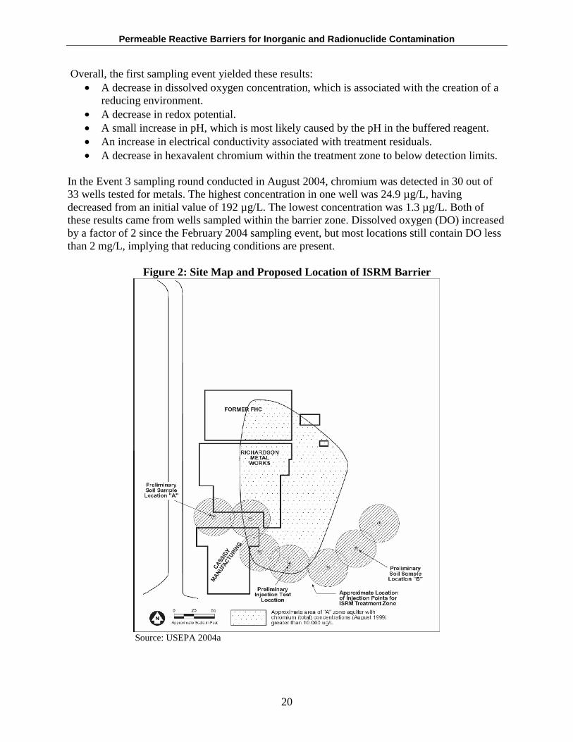
A pilot study confirmed that the hydraulic properties at the site were highly variable. Eight injections using the sonic method, except one that was done using a hollow stem auger, occurred between May through early August 2003. The ISRM barrier measured 250 ft in length and 168,000 lbs of dithionite and pH buffer were mixed in a potassium carbonate buffer solution to create 560,000 gallons of reagent. The locations of the injections are shown in Figure 2.
The first sampling event took place four months after the initial ISRM installment. Iron exceeded the MCL following treatment in several wells, as did manganese, which on average increased to levels approximately 40 times the secondary MCL. These increases are similar to that observed following the pilot test and indicate that, as expected, iron and manganese were mobilized by the reductive treatment. Arsenic also showed indication of mobilization, which at several locations within the treatment zone increased by approximately two to four times its primary MCL. Aluminum, barium, cobalt, and nickel also increased, but did not exceed their MCLs. Hexavalent chromium concentrations were reduced from as high as 8,500 µ g/L in the center of the plume to below detection limits (~0.01 µg/L) in all monitoring wells.
19
Permeable Reactive Barriers for Inorganic and Radionuclide Contamination
Overall, the first sampling event yielded these results: • A decrease in dissolved oxygen concentration, which is associated with the creation of a
reducing environment. • A decrease in redox potential. • A small increase in pH, which is most likely caused by the pH in the buffered reagent. • An increase in electrical conductivity associated with treatment residuals. • A decrease in hexavalent chromium within the treatment zone to below detection limits.
In the Event 3 sampling round conducted in August 2004, chromium was detected in 30 out of 33 wells tested for metals. The highest concentration in one well was 24.9 µg/L, having decreased from an initial value of 192 µ g/L. The lowest concentration was 1.3 µg/L. Both of these results came from wells sampled within the barrier zone. Dissolved oxygen (DO) increased by a factor of 2 since the February 2004 sampling event, but most locations still contain DO less than 2 mg/L, implying that reducing conditions are present.
Figure 2: Site Map and Proposed Location of ISRM Barrier
Source: USEPA 2004a
20
Permeable Reactive Barriers for Inorganic and Radionuclide Contamination
The lifetime of the barrier was investigated by evaluating the distribution of reductive capacity along sections of the barrier. Portions of the barrier located downgradient of the treatment area where only limited oxidizing species concentrations are expected are estimated to last well over 1,000 years. Portions of the barrier where the reactive media distribution may not be homogenous are estimated to last more than 40 years. Based on these investigations, the barrier should last long enough in order to meet remedial goals.
Sources: USEPA 2004a; Event 3: Long-term Monitoring Report – August, 2004.
Contact Information: Sean Sheldrake USEPA Email: [email protected]
3.1.8 Haardkrom Site, Kolding, Denmark
Reactive Media: ZVI Contaminants: Trichloroethylene (TCE) and Hexavalent chromium (Cr(VI)) Configuration: Continuous Trench Installation Date: 1999 Cost: $358,000
The Haardkrom site formerly operated as an electroplating facility in Kolding, Denmark, where chromium, nickel, zinc, and the degreasing agent, TCE, were used. The groundwater was consequently contaminated with high levels of TCE and Cr(VI). TCE concentrations initially ranged from 40 to 1,400 µg/L while Cr(VI) concentrations varied from 8 to 110 mg/L.
The aquifer varies in depth, but is approximately 6.6 ft bgs in sandy loam. Laboratory experiments predicted that the Cr(VI) reduction was on the order of 1-3 mg Cr(VI)/g of ZVI. A PRB was installed in 1999. Its dimensions were 164 ft long x 3.3-9.8 ft deep x 3.3 ft thick. Bypass trenches and recirculation pipes were installed to increase flow through the PRB.
After one year, the PRB was not effectively treating the contaminated plume. It has been speculated that the uneven distribution of the ZVI in the plume depleted the iron-chromate removal capacity of the wall.
Source: Roehl et al., 2005.
Contact Information: Peter Kjeldsen Technical University of Denmark Environmental & Resources DTU Building 115 DTU, DK-2800 Kgs. Lyngby Denmark Tel: +45 45251561 Fax: +45 45932850 Email: [email protected]
21
Permeable Reactive Barriers for Inorganic and Radionuclide Contamination
3.1.9 Nickel Rim Mine Site, Sudbury, Ontario, Canada
Reactive Media: Organic Carbon Contaminants: Nickel, Iron, Sulfate Configuration: Cut and Fill, full scale Installation Date: August 1, 1995 Cost: $35,000
This site is located 25 km northeast of Sudbury, Ontario and is overlain by silty-sand size sulfur-contaminated tailings that cover 9.4 ha and are approximately 10 m deep. Groundwater has been contaminated with SO4 (2,400-5,000 mg/L), Fe (200-2,000 mg/L), and minor amounts of Cu and Ni. The aquifer is 3-8 m thick and is bounded on both sides and below by bedrock. The groundwater moves about 15 m/year. The main concern at this site is the potential of acid mine drainage discharging into a nearby lake.
A PRB containing a mixture of municipal compost (20%), leaf mulch (20%), wood chips (9%), gravel (50%), and limestone (1%) was installed downgradient of the tailings mound. The barrier is 20 m wide, 3.5 m deep and 4 m thick and is keyed into the bedrock. Sand buffer zones 1 m thick were put in place upgradient and downgradient of the barrier, and a clay cap about 0.4 m thick was placed overhead to prevent infiltration of oxygen and rainwater.
A sampling event nine months after installation showed that contaminants declined significantly. SO4 declined by more than 1,000 mg/L, Fe decreased to 50 mg/L and within some points in the barrier, to < 1 mg/L. The barrier also reduced acidity and created alkaline conditions. Sulfate-reducing bacteria are at a population of 5 orders of magnitude greater around the barrier than within the aquifer.
After three years of sampling, Fe decreased by 50%, SO4 by 30%. There has been a downward trend in the treatment performance due to the consumption of more readily oxidizeable organic carbon in the barrier. There are also seasonal and spatial differences in the rate of SO4 and Fe removal within the barrier. SO4 removal varies at different locations within the barrier itself, which is attributed to groundwater flow differences. Seasonally, removal rates are nearly twice that in the fall than in the spring, which is attributable to changing groundwater temperatures that vary from 3ºC in winter to 15ºC in summer.
Removal of contaminants is effectively occurring by sulfate reduction and precipitation of metal sulfides. The rate of reducing heavy metals to metal sulfides has been consistent from two to seven years after PRB installation. Downgradient of the barrier, oxidized phases of Mn and Fe, Cr(III) associated with Fe, and poorly crystalline Zn are lower. The oxidized phases of Mn and Fe have the potential to release metals into the groundwater if reducing conditions arise.
Sources: Naftz et al., 2002; RTDF, 2000b; Doerr et al., 2005.
22
Permeable Reactive Barriers for Inorganic and Radionuclide Contamination
Contact Information: David W. Blowes University of Waterloo Waterloo Centre for Groundwater Research Waterloo, Ontario Canada Tel: 519-888-4878 Fax: 519-746-5644 Email: [email protected]
3.1.10 Savannah River Site TNX Area, Aiken, South Carolina
Reactive Media: ZVI Contaminants: Metals (Al), chlorinated solvents Configuration: GeoSiphon cell, pilot scale Installation Date: July 1997 Cost: Information not available
The Savannah River Site (SRS) is located .25 miles from the Savannah River in Aiken, SC. The TNX Area on the site produces steam and electricity in a moderate-to-low sulfur coal-burning power plant. Most of the coal is stored in an open pit where runoff is directed into a coal pile runoff basin to remove suspended solids. Sulfuric acid, produced by long-term chemical and biological oxidation of the sulfur compounds within the coal, has leached other impurities from the coal, and the rainwater has infiltrated the groundwater, resulting in elevated levels of iron, aluminum sulfate, and minor concentrations of lead, cadmium, and TCE.
The contaminants of concern at the TNX Area are only found in the shallow aquifer and not in semi-confined or deep aquifers. The aquifer underneath the site is 35-40 ft thick, is 5 ft bgs, and is composed of a mixture of sand, silty sand, and thin clay layers. The horizontal hydraulic conductivity is 5 x 10⁻⁵ m/s, vertical conductivity of 12 m/s. The porosity is 0.15, pore velocity is 3 ft/day, and horizontal gradient is 0.007.
Two GeoSiphon cells were installed in 1997. The first cell was installed for the treatment of TCE, whereas the second cell was installed to treat metals-contaminated water. The second cell consists of a 4.6 - 4.9 m deep by 0.6 m wide by 12.2 m long trench filled with limestone with two horizontal slotted pipes embedded within the limestone. This cell was designed to raise the pH enough to precipitate the aluminum, chromium, and remaining metals. Groundwater flow was induced by an 8 ft diameter GeoSiphon containing ZVI. This cell increased the pH from 2.2 to 4.5 and reduced Al concentrations by 61%.
Two lessons learned are worth noting. The optimal pH for removal of ferric iron is 8, which was not achieved during the study. The addition of lime or sodium hydroxide solution may have helped to raise the pH. The most effective metals removal was produced by a secondary treatment of calcium peroxide and hydrogen peroxide/sodium carbonate, but controlling the effluent pH was more troublesome when using sodium hydroxide even though it was more effective. Neither of the cells was promoted to a full-scale application.
Source: Naftz et al., 2002; Phifer et al., 2005.
23
Permeable Reactive Barriers for Inorganic and Radionuclide Contamination
Contact Information: Mark Phifer Westinghouse SRC/SRS Building 773-42A
Aiken, SC 29808 Tel: 803-725-5222 Fax: 803-725-7673 Email: [email protected]
3.1.11 Tonolli Superfund Site, Nesquehoning, Pennsylvania
Reactive Media: Limestone Contaminants: Arsenic, Antimony, Cadmium, Copper, Lead, Zinc Configuration: Continuous Trench, pilot scale Installation Date: August 1998 Cost: $376,000
Tonolli Corp., a lead battery recycling center, operated on a 20-acre site in Nesquehoning, PA, from 1974 to 1985. There is an onsite landfill with 84,700 yd3 of waste and a surface impoundment that holds 2 million gallons of water contaminated with As, Cd, Pb, and Cr from plant operations. Liquid from the impoundment would occasionally leak and infiltrate the landfill. In June 1988, the U.S. EPA used CERCLA emergency funds to start cleanup when tests revealed As, Cd, and Pb in Nesquehoning Creek three miles downstream. The site is located in a sparsely populated area of Carbon County where well water is prevalent. The Tonolli site was formally added to the NPL on October 4, 1989.
Maximum concentrations of contaminants were Pb (328 µg/L), Cd (77 µ g/L), As (313 µg/L), Zn (1,130 µg/L), and Cu (140 µg/L). Contamination is located at 0-19 ft bgs and in the alluvium from 74-113 ft. A limestone trench was selected as one of several cleanup remedies. The trench was constructed parallel to the Creek and its dimensions are 3 ft wide x 24 ft deep x 1,400 ft long. 2002 data shows that the trench has been effective in reducing Pb concentrations to below performance standards. Cd levels are decreasing, but have not yet met the performance standard. Arsenic and Antimony show increased levels downgradient of the landfill, and may be subjected to seasonal groundwater fluctuations.
Groundwater cleanup goals have since been achieved in the deep aquifer, but not the shallow aquifer where Cadmium, Antimony, and Arsenic are present in the shallow aquifer above cleanup goals. This site is in the final process of cleanup and is underway to be deleted from the NPL list. Long-term performance monitoring is ongoing.
Source: USEPA, 2005b.
24
Permeable Reactive Barriers for Inorganic and Radionuclide Contamination
Contact Information: John Banks USEPA Region 3 3HS22 1650 Arch Street Philadelphia, PA 19103-2029 Tel: 215-814-3214 Fax: 215-814-3002 Email: [email protected]
3.1.12 Universal Forest Products, Inc., Granger, Indiana
Reactive Media: Calcium polysulfide Contaminants: Chromium Configuration: Combination of pump-and-treat and PRB Installation Date: September 1995 Cost: Information not available
Universal Forest Products (UFP) opened Great Lakes Wood Preserving, a wood treatment plant, in 1981 at Granger, Indiana. Spills and leaks contaminated the groundwater with Cr(VI), Cu, and As. UFP tried to treat and contain the contamination by using pump-and-treat technologies, which worked for off-site, but not for on-site, contamination, so further action was necessary.
A combination of pump-and-treat and PRB technologies was developed in September 1995 at the South Area of the site. Groundwater was pumped from a recovery well and then treated with 29% calcium polysulfide in a series of pipes before being discharged to a bag filter. This process reduced Cr(VI) to Cr(III) through the oxidation of S2- to S0. The treated water was then reinjected to the subsurface by a horizontal infiltration pipework located 3 ft bgs, where the Cr(VI) interacts with the soil particles by electrostatic interactions. This process reduces Cr(VI) to Cr(III) to form immobile oxyhydroxide solids. The same type of technology was installed at the South Area, except that there were two submersible groundwater pumps instead of one.
A certificate of completion was issued and the site was listed as completed on April 20, 1999 after five years and two months of remediation efforts. Chromium contamination has been consistently either at or below the MCL.
Source: Ott, 2001.
Contact Information: Carla Gill Indiana Department of Environmental Management
100 North Senate Avenue PO Box 6015 Indianapolis, IN 46206-6015
Tel: (317) 232-8603
25
Permeable Reactive Barriers for Inorganic and Radionuclide Contamination
3.1.13 U.S. Coast Guard Support Center, Elizabeth City, NC
Reactive Media: ZVI Contaminants: Chromium, Trichloroethylene Configuration: Continuous Trench, full scale Installation Date: June 1, 1996 Cost: $675,000
After five years of operation, the barrier is continuing to remove both contaminants and is expected to have the same level of reactivity and hydraulic performance for at least the next five years. Chromium has consistently been reduced to below MCL downgradient of the barrier. The barrier is slowly losing its ability to create reducing conditions, which will affect performance in the future.
Source: USEPA, 2003 a & b.
Contact Information: Robert W. Puls USEPA National Risk Management Research Laboratory P.O. Box 1198 Ada, OK 74820 Tel: 580-436-8543 Fax: 580-436-8706 Email: [email protected]
3.1.14 Vancouver Site, Acid Mine Drainage
Reactive Media: Organic Carbon Contaminants: Cadmium, Copper, Nickel, Zinc Configuration: Cut and Fill, pilot scale Installation Date: March 1997 Cost: $31,000
The Vancouver site is located on the shoreline of a marine inlet. Groundwater contamination includes Cd, Cu, Ni, and Zn and is limited to the upper 15 m of the unconfined aquifer, with the highest concentrations in the upper 6 m. The aquifer is affected by tidal fluctuations of the adjacent marine inlet.
A demonstration barrier was installed in March 1997 that consists of 84% pea gravel, 15% leaf compost, and 1% limestone. Contamination was present up/downgradient and below the barrier. A guar gum slurry was used during installation to prevent wall collapse. This will biodegrade naturally or with the addition of an enzyme mixture. The barrier is 2.5 m wide, 6.7 m deep and 10 m long and was placed 50 m inland from the shoreline.
Overall, the barrier is performing as expected. Treatment efficiency of heavy metal contaminants has increased with time, and many are below detectable limits in the effluent. Removal rates
26
Permeable Reactive Barriers for Inorganic and Radionuclide Contamination
decreased with time, but leveled off after one year, due in part by reduced metal concentrations entering the barrier.
The maximum tidal fluctuation around the barrier is 1.45 m between high and low tides and has had an effect on removal efficiency of the barrier. Deeper portions have a higher removal rate than those in shallower portions due to the flushing of oxygen-rich pore gas through the shallow barrier caused by the tidal-induced raising and lowering of the water table. To overcome this treatment difference, a full-scale barrier should be thicker in the shallower portion of the aquifer. Capping the barrier will also limit infiltration of diffused oxygen and surface water into the barrier.
Source: Naftz et al., 2002.
Contact Information: Ralph Ludwig Technical Assistance Technology Transfer Branch USEPA National Risk Management Research Laboratory
919 Kerr Research Drive Ada, OK 74820
Tel: 580-436-8603 Email: [email protected]
3.1.15 Wheel Jane Tin Mine, Cornwall, UK
Reactive Media: Sawdust, hay, cow manure Contaminants: Iron, zinc, copper, cadmium Configuration: Compost Bioreactors, pilot scale Installation Date: 2000 Cost: Information not available
Three compost bioreactors consisting of 95% softwood sawdust, 5% hay, and a small amount of cow manure were installed at the site in 1995, and then replaced in 2000. Each barrier is 87.5 m long x 8.75 m wide x 1 m deep and is 400 mm bgs. The performance was studied for a period of 16 months. These reactors were installed to counteract the effects of acid mine drainage by increasing pH and removing heavy metals, mainly iron and zinc, from groundwater.
The first bioreactor was lime-dosed (LD), the second was an anoxic limestone drain (ALD), and the third was lime-free (LF). Sampling showed that a pH increase and a decrease in the concentration of metals occurred in all three bioreactors, but only the LF cell showed an effective removal. Soluble sulfides were present in the effluent of all three areas, but LF had the lowest concentrations due to the fact that almost 99% of the heavy metals were removed. The pH was too low for FeS generation in the LD and ALD reactors. Reacidification occurred downstream of these two systems because of the oxidation and hydrolysis of iron and sulfide oxidation. Future studies should place the bioreactor ahead of the aerobic cells to avoid this problem. SRBs were also only present in the LF cell.
27
Permeable Reactive Barriers for Inorganic and Radionuclide Contamination
The LF cell by far was the most effective bioreactor of the three. This was most likely due to the fact that it was shut down for 10 months prior to this study because of operational problems. This time apparently allowed AMD-tolerant microbial populations to flourish. The other two cells should have been allowed to mature microbiologically before operation.
Source: Johnson & Hallberg, 2005.
Contact Information: D. Barrie Johnson School of Biological Sciences Memorial Building
Deiniol Road Bangor LL57 2UW, UK
3.1.16 Zenaca Ag Products/Campus Bay, Richmond, California
Reactive Media: Compost: leaf material with soil/sand mix Contaminants: Acid Mine Drainage (low pH, heavy metals) Configuration: Full Scale Installation Date: 2002
Performance monitoring was transferred from the San Francisco Regional Water Quality Board to the Department of Toxic Substances Control in late 2004, and comments regarding the performance since that time are unavailable. The only information available about this site are the dimensions of the PRB, which is ¼ mile long × 20 ft deep × 2 ft wide and was installed to treat waste pyrite cinders created from mining operations. Although, no specific data were available, the barrier has been performing as expected and SRBs are also present.
Source: ITRC, 2005.
Contact Information: Lynn Nakashima CA Regional Water Board
Department of Toxic Substances Control Phone: 510-540-3839 Email: [email protected]
3.2 Case Studies: Radionuclides
3.2.1 Bodo Canyon Disposal Site, La Plata County, Colorado
Reactive Media: ZVI, Copper Wool, Steel Wool Contaminants: Arsenic, Molybdenum, Selenium, Uranium, Vanadium, Zinc Configuration: Collection drain piped to underground system, pilot-scale Installation Date: October, 1995 Cost: $380,000
From 1987 to 1990, DOE relocated 2.5 million yd3 of tailings and contaminated soils from a mill site located just outside of Durango, CO, to the Bodo Canyon disposal site in La Plata County,
28
Permeable Reactive Barriers for Inorganic and Radionuclide Contamination
CO, 3.5 miles southwest of Durango, CO. A low-permeability liner was placed under the disposal cell and, due to the slope of the land, a toe drain and holding pond were constructed. The pond was treated periodically and discharged according to the proper permit.
The underlying bedrock is composed of sandstone. A shallow aquifer occurs within the alluvium of the valley northeast of the disposal cell, and varies seasonally. The hydraulic conductivity of the alluvium averages 0.13 ft/day, porosity is 0.25, with a gradient of 0.003 down the valley center. Flow varies from 0.6 ft/year to 140 ft/year.
Hazardous constituents include As, Mo, Se, U, V, and Zn. Initially, contaminant concentrations in the untreated water were 186 µg/L for As, 1,180 µg/L for Mo, 337 µ g/L for Se, 5,540 µg/L for U, 8,800 µg/L for V, and 1,600 µg/L for Zn.
Contaminated water from the toe drain (328 ft long x 4 ft wide x 3 ft high) goes to a holding tank, which directs the water to a manifold where it goes through any of four pilot-scale PRBs. The PRBs were installed in 1995 with different reactive materials to compare treatment efficiencies. Flow rates varied from 0.3 to 2 gpm. PRB A contained steel wool, while PRB B was constructed of steel wool and copper wool. Both were 20 ft wide x 3 ft long x 7 ft high, and had reactive media 12 in thick. PRB A never worked, and PRB B operated for one year. PRBs C and D were 6 ft long x 3 ft wide x 4.2 ft deep with steel baffles that allowed the water to flow up and down through it. PRB C was constructed of ZVI foam plates whereas PRB D used steel wool. Approximately 70 ft3 of reactive media was used in each. PRB D ran for two months. In 1999, reactive material in PRB C was excavated and replaced with Peerless -8 + 20 mesh granular ZVI and renamed PRB E.
At PRB E, incoming concentrations of Mb were ~1 mg/L, and were removed in the effluent, but after several hundred pore volumes, a slight increasing trend occurred. Effluent U concentrations remained less than 0.01 mg/L. Calcium dropped 10%, and pH values increased from 6.7 to 7.4. PRB E operated from August 1999 until June 2004 when flow ceased from the seep, and remediation was no longer needed. It was highly effective in treating contaminants below their detection limits, and no full-scale units are needed.
Sources: DOE, 1996; RTDF, 2001c; Personal Communication with Stan Morrison, Ph.D.
Contact Information: Stan Morrison, Ph.D. Environmental Sciences Laboratory 2597 B 3/4 Road Grand Junction, CO 81503 Tel: 970-248-6373 Fax: 970-248-6040 Email: [email protected]
29

Permeable Reactive Barriers for Inorganic and Radionuclide Contamination
3.2.2 Chalk River Laboratories, Ontario, Canada
Reactive Media: Granular Zeolite (Clinoptilolite) Contaminants: Strontium-90 Configuration: Wall and Curtain, full scale Installation Date: November 1998 Cost: $300,000
The Atomic Energy of Canada, Ltd. (AECL) owns and operates the Chalk River Laboratories in Canada where, in the early 1950s, the site was operated to decompose and reduce ammonium nitrate solutions containing mixed fission products. Some solutions were released into a pit of crushed limestone. A Strontium-90 (Sr-90) contaminated plume is located within the deeper end of a 12 m thick aquifer, and has migrated about 440 m downgradient from its source to Duke Swamp. The groundwater moves approximately 150 m/day, but because of geochemical interactions, it took the leading edge of the plume 40 years to reach Duck Swamp. The saturated thickness of the aquifer varies from 5 to 13 m thick, and the hydraulic conductivity of the sandy aquifer is 10-4 to 2 x 10⁻⁵ m/s.
A PRB was installed in 1998 to counteract the migration of the Sr-90-contaminated plume into this wetlands area. The wall and curtain consists of a sealed-joint, steel-sheet pile, cut-off wall located downgradient of a granular zeolite curtain or barrier. The cut-off wall extends 9.5 to 12 m into the bedrock to prevent groundwater backflow, and is 30 m long. The reactive media consists of a 130 m3 granular curtain of 14 x 50 mesh clinoptilolite, which is a mineral in the zeolite group. Zeolites are able to lose and absorb water without damage to their crystal structures, have a large pore space, and are chemically neutral in structure (Energy Web, 2002). The reactive barrier is 2 m long x 11 m wide and extends about 6 m bgs.
Two drainage systems hydraulically control the flow through the treatment zone and allow for performance monitoring at a single discharge pipe.
1) Ten vertical, continuously slotted well screens are located in the curtain in front of the wall. The wells are linked to a drain that terminates with a flexible outflow hose to allow for adjustments in outflow elevation and performance measurement at a single pipe.
2) A second drainage pipe was located across the path of the groundwater 60 m upgradient of the wall and curtain to divert shallow, uncontaminated groundwater from the treatment system in order to extend its lifespan.
Initially, concentrations of Sr-90 in the groundwater ranged from 0.1 – 100 Becquerel (Bq)/L. As of 2001, the PRB has treated 1.5 x 10⁷ L/yr of Sr-90-contaminated groundwater from entering the wetlands, while diverting 107 L/yr of shallow uncontaminated groundwater, which would otherwise enter the PRB and decrease its reactivity. The system has captured about 99.5% of the Sr-90 in the plume as it travels through the barrier. Leakage is occurring underneath the PRB at a rate of 2.7 L/min because the steel-sheet pilings were not grouted to the bedrock, but because the flow can be controlled, it is not seen as a major problem. Overall, the system is performing as intended and Sr-90 concentrations are essentially non-detectable in the effluent.
30
Permeable Reactive Barriers for Inorganic and Radionuclide Contamination
AECL cited three lessons learned: • The team should have sand-packed the dewatering wells with reactive material better. • The subcontractors should have been properly informed about the aquifer by AECL,
instead of by the contractor. • The PRB should have been grouted to the bedrock. • Roots should have been cleared from the area prior to installation so as not to create a
delay.
The subsurface wall and curtain configuration of the PRB was chosen because test results showed that the groundwater capture zone is hydraulically adjustable, or in other words, it can be sized both vertically and horizontally to fit plume dimensions. (RTDF 2001d). The flow and concentration of groundwater passing through the PRB can be directly measured. This system saved AECL approximately $200,000 per year by not using pump-and-treat technology. In light of this, the PRB paid for itself in less than two years and is still operating effectively.
Sources: All sources from Lee, D.R.; Hartwig, D.S., 2001 unless otherwise noted.
Contact Information: David R. Lee Environmental Technologies Branch Email: [email protected] Station 51A Chalk River Laboratories Chalk River, Ontario K0J 1J0 Canada Tel: 613-584-8811 Ext: 4710 Fax: 613-584-1221
3.2.3 Cotter Corporation Uranium Mill, Cañon City, Colorado
Reactive Media: ZVI Contaminants: Molybdenum (Mb) and Uranium (U) Configuration: Funnel and gate, pilot scale Installation Date: June 2000 Cost: Information not available
Groundwater flows through an alluvium composed of unconsolidated sand, gravel, and silt, and overlies a bedrock mixture of claystone, sandstone, and coal. Saturated thickness ranges from 0.5 to greater than 4 ft in the vicinity of the PRB, and varies seasonally. Groundwater flux is estimated to be 1 gal/min at the PRB site. The groundwater at this previous uranium-ore milling site has been contaminated with molybdenum and uranium at mean concentrations of 4.8 and 1.0 mg/L for Mb and U, respectively.
A funnel and gate PRB was installed in June 2000 and is perpendicular to groundwater flow. The PRB is 30 ft wide x 7 ft high and composed of a 5 ft long zone of ZVI with 2 ft of clean silica on either side. Approximately 80 tons of ZVI was used. The concrete walls extend 285 ft to the west
31
Permeable Reactive Barriers for Inorganic and Radionuclide Contamination
and 85 ft to the east. The PRB was keyed into the claystone/coal bedrock about 25 ft bgs and captures nearly all of the contaminated groundwater.
Mean Mb concentrations were less than 0.2 mg/L, and U was less than 0.01 mg/L at the PRB site. These results were consistent from June 2000 until April 2001 when Mb concentrations began to increase, but were still below 1 mg/L. By January 2003, Mb samples within the barrier exceeded incoming levels. Samples were as high as 19 mg/L, which suggested that the PRB had stopped working effectively. Mounding occurred simultaneously with the increase in Mb concentrations. U concentrations remained at less than 0.006 mg/L.
Results from November 2003 indicated that some water was migrating around the PRB, and by October 2004, very little groundwater was permeating through the barrier. Part of the barrier was excavated in October 2004, and it was found that the ZVI was clogged by mineral precipitants. Nearly all U precipitates were within 0.5 ft of the front wall of the PRB, and concentrations ranged from 5 to 3,727 µg/g. The same occurred with Mb, where concentrations ranged from 130 to 4,050 µg/g. Calcium carbonate, iron oxides, and sulfide minerals were also present.
Recommendations to improve treatment efficiency are: 1) Install an accessible treatment system that can be easily manipulated and monitored. 2) Flush the existing system with weak acid to restore hydraulic conductivity. 3) Install a pretreatment zone composed of coarse gravel and ZVI.
Source: DOE 2005a.
Contact Information: None available.
3.2.4 Fry Canyon site, Fry Canyon, Utah
Reactive Media: ZVI, Amorphous ferric oxide (AFO), Phosphate rock Contaminants: Uranium Configuration: Funnel and Gate, pilot scale Installation Date: August 1997 Cost: $140,000
Subsurface drainage from mill ponds at this abandoned uranium ore milling and copper leach operation have led to groundwater contaminated with uranium at concentrations ranging from 60 µg/L in a distant well to 20,700 µg/L underneath a tailings pile. The water table at this site is 8-9 ft bgs and the underlying aquifer is 1-6 ft deep. Groundwater flow in the alluvial aquifer is approximately 1.5 ft/day and is parallel to the stream flow. Hydraulic conductivity is about 1,500 ft/day within the poorly sorted fine- and medium-grained sands.
Three pilot scale PRBs were installed side by side for concurrent remediation: 1) phosphate rock; 2) foamed ZVI pellets; and 3) AFO. Each barrier treats metals differently: 1) precipitation by phosphate; 2) reduction of U(VI) to U(IV) by ZVI; and 3) by adsorption to the ferric oxyhydroxide surface. Each measures 7 ft wide x 3 ft thick x 4 ft deep and was filled with approximately 110 ft3 of reactive media.
32
Permeable Reactive Barriers for Inorganic and Radionuclide Contamination
Influent concentrations of U differed in each barrier, ranging from less than 1,000 mg/L in the phosphate barrier to more than 20,000 mg/L in the AFO barrier. Seasonal variations were also evident. The ZVI barrier has been the most effective by removing 99.9% of uranium. The phosphate and AFO barriers performed slightly under the ZVI barrier; removal rates also varied. U removal by the phosphate barrier averaged 99% in the initial phase, but by January 1998, removal rates decreased to 60-70%, and then increased back up to 98% in September 1998. The increase is thought to be caused by leaking water already treated from the ZVI barrier. A 50% chemical breakthrough was seen in the AFO barrier, which also consistently had the lowest removal rate. This was speculated to be caused by variation in pH because AFO is highly dependent upon it. The removal rate was inversely proportional to increases in pH.
There has been a decreasing trend in groundwater velocities. In 1999, the groundwater velocity was 1.54 m/day. In 2003, it decreased to 0.95 m/day and in 2005, it was only 0.4 m/day. A slight mounding effect has also occurred. An increase in precipitates of carbonate and sulfide as shown by a decrease in both constituents in the effluent may be the cause. The pH increased from 8.5 during 1997 – 2000 to more than 10.0 during 2003 – 2005. This directly correlates to an increased level of calcium removal from the groundwater. Increased amounts of dissolved sulfate are also linked to increased rates of bacterially mediated sulfate reduction.
Source: Naftz et al., 2002; Personal Communication with David N. Naftz, Ph.D. July 29, 2005.
Contact Information: David N. Naftz , Ph.D. U.S. Geological Survey1745 W. 1700 South Salt Lake city , UT 84104 Tel: 801-975-3389 Fax: 801-975-3424 Email: [email protected]
3.2.5 Mecsek Ore, Pecs, Hungary
Reactive Media: ZVI, shredded cast iron Contaminants: Uranium Configuration: Continuous barrier, pilot scale Installation Date: August 2002 Cost: Information not available
This former mining site was located near Pecs in Southern Hungary and encompasses a total area of 163 ha. The area was mined from 1958 until 1962, when milling began, and was shut down in 1997 for economic reasons. A total of 20.3 million tons of uranium tailings from the milling process were placed with about 32 million m3 of process water in two tailings ponds (Site I). Tailings from the mining process were sorted into three waste rock piles (WRP). Site II contains the Heap Leaching Area II and WRP I. WRP I contains ~1.3 million tons and has a U concentration of 10 mg/L under the waste rocks, which decreases to 37-65 µ g/L a few hundred meters downstream. Only a small portion of the leachate is collected; the rest drains into the subsurface. WRP II is composed of 4.4 million tons of waste with a U concentration in the
33
Permeable Reactive Barriers for Inorganic and Radionuclide Contamination
leachate of 20-30 mg/L. Most of the leachate is collected and treated from this pile. WRP III, the largest pile, contains 12.3 million tons of rock and is located above the mine area. Water is being pumped and treated from the mine area below ground to prevent groundwater contamination, and because of this, a cone of depression has formed. Leachate from WRP III infiltrates the subsurface. Site III is the valley below WRP III, where uranium-contaminated water is present. In 2000, the U concentration was 800 µg/L and has been increasing. Site IV contains the mill site and heap leaching area I. U-contaminated soil was removed in 1999, and the area was capped in 2000.
Site III contains permeable sandy sediment layers with a permeability of 10-4 to 10-6 m/s between clay layers. Site III was chosen for the location of the PRB because of the increasing levels of U and its subsurface characteristics.
The pilot-scale barrier was installed perpendicular to the valley of Site III and was designed to be 6.8 m long x 2.5 m thick x 3.8 m deep consisting of two different zones emplaced with ZVI and sand. Zone I is 50 cm thick with 12% by volume of coarse ZVI. Zone II is 1 m thick with 41% by volume of fine ZVI. Sand layers 50 cm thick were placed on both sides of the PRB to enhance groundwater flow. The PRB was lined with clay and geosynthetic clay liners underneath, with a geomembrane at both ends and on top, and was then covered with a layer of clay. The hydraulic gradient at the site is between 0.04 and 0.06 and groundwater flow velocity is about 0.086 m/day. The average hydraulic conductivity is 3.36 x 10⁻³ m/s.
U concentrations within the groundwater in the year 2003 were reduced to less than 1% of its influent value after passing through the PRB. Concentrations dropped from ~1,000 µg/L to ~ 100 µg/L in surrounding monitoring wells, and to less than 10 µg/L within the barrier. Groundwater pH increased from 7.15 to 9-10, and has been stable over the observation period. The estimation of precipitates that have formed is high (525 kg/year), which may lead to reduced reactivity or hydraulic conductivity over the long-term. The porosity of the iron/sand mixtures is 30%, and the annual loss in porosity is estimated to be 1.6% per year. From this data, a 62-year lifespan was predicted for the barrier.
Source: Roehl et al., 2005.
Contact Information: None available
3.2.6 Monticello Mill Tailings site, Monticello, Utah
Reactive Media: ZVI Contaminants: Uranium (U), Arsenic (As), Manganese (Mn), Molybdenum (Mo),
Selenium (Se), Vanadium (V), Nitrates (NO3) Configuration: Funnel and Gate, full scale Installation Date: June 30, 1999 Cost: $800,000
The Monticello site in southeastern Utah was contaminated with a uranium plume due to the processing of uranium and vanadium bearing ore from the mid-40s until 1960. The site was
34
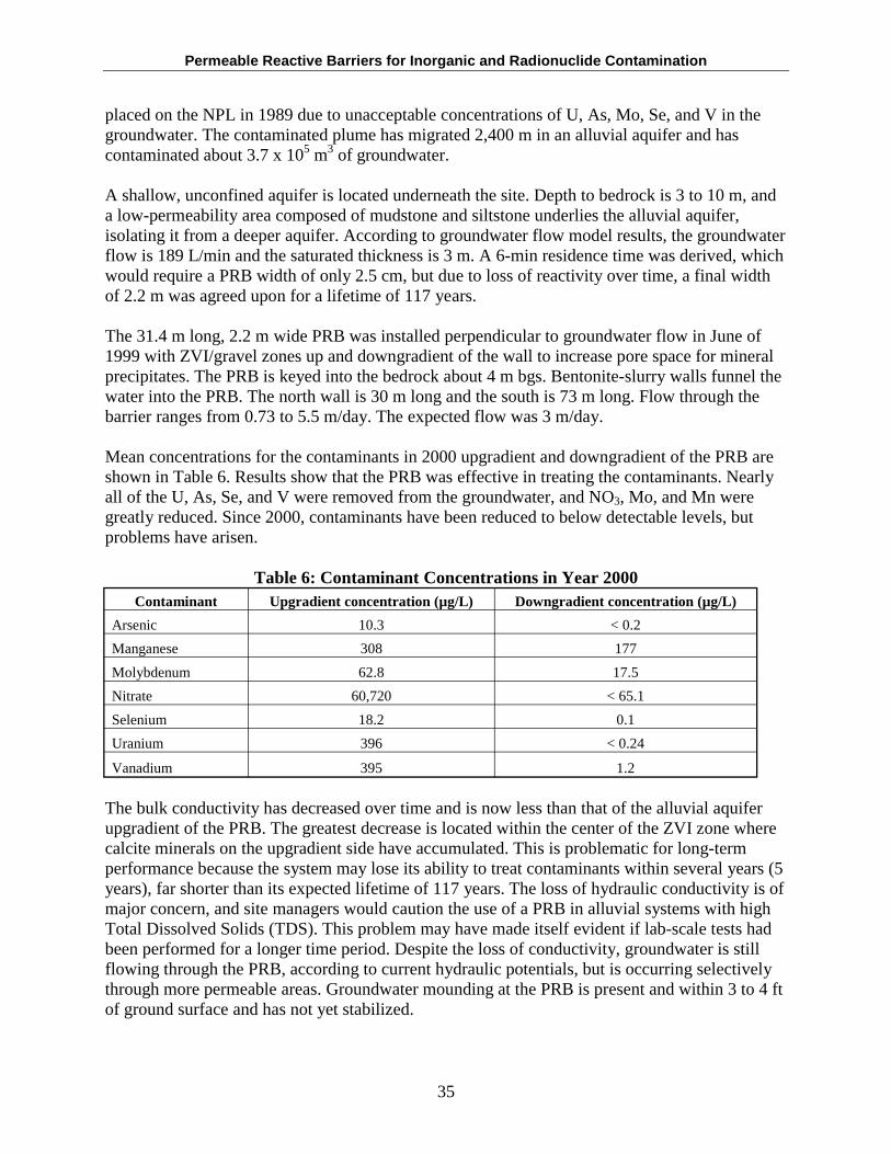
Permeable Reactive Barriers for Inorganic and Radionuclide Contamination
placed on the NPL in 1989 due to unacceptable concentrations of U, As, Mo, Se, and V in the groundwater. The contaminated plume has migrated 2,400 m in an alluvial aquifer and has contaminated about 3.7 x 10⁵ m3 of groundwater.
A shallow, unconfined aquifer is located underneath the site. Depth to bedrock is 3 to 10 m, and a low-permeability area composed of mudstone and siltstone underlies the alluvial aquifer, isolating it from a deeper aquifer. According to groundwater flow model results, the groundwater flow is 189 L/min and the saturated thickness is 3 m. A 6-min residence time was derived, which would require a PRB width of only 2.5 cm, but due to loss of reactivity over time, a final width of 2.2 m was agreed upon for a lifetime of 117 years.
The 31.4 m long, 2.2 m wide PRB was installed perpendicular to groundwater flow in June of 1999 with ZVI/gravel zones up and downgradient of the wall to increase pore space for mineral precipitates. The PRB is keyed into the bedrock about 4 m bgs. Bentonite-slurry walls funnel the water into the PRB. The north wall is 30 m long and the south is 73 m long. Flow through the barrier ranges from 0.73 to 5.5 m/day. The expected flow was 3 m/day.
Mean concentrations for the contaminants in 2000 upgradient and downgradient of the PRB are shown in Table 6. Results show that the PRB was effective in treating the contaminants. Nearly all of the U, As, Se, and V were removed from the groundwater, and NO3, Mo, and Mn were greatly reduced. Since 2000, contaminants have been reduced to below detectable levels, but problems have arisen.
Table 6: Contaminant Concentrations in Year 2000 Contaminant Upgradient concentration (µg/L) Downgradient concentration (µg/L)
Arsenic 10.3 < 0.2
Manganese 308 177
Molybdenum 62.8 17.5
Nitrate 60,720 < 65.1
Selenium 18.2 0.1
Uranium 396 < 0.24
Vanadium 395 1.2
The bulk conductivity has decreased over time and is now less than that of the alluvial aquifer upgradient of the PRB. The greatest decrease is located within the center of the ZVI zone where calcite minerals on the upgradient side have accumulated. This is problematic for long-term performance because the system may lose its ability to treat contaminants within several years (5 years), far shorter than its expected lifetime of 117 years. The loss of hydraulic conductivity is of major concern, and site managers would caution the use of a PRB in alluvial systems with high Total Dissolved Solids (TDS). This problem may have made itself evident if lab-scale tests had been performed for a longer time period. Despite the loss of conductivity, groundwater is still flowing through the PRB, according to current hydraulic potentials, but is occurring selectively through more permeable areas. Groundwater mounding at the PRB is present and within 3 to 4 ft of ground surface and has not yet stabilized.
35
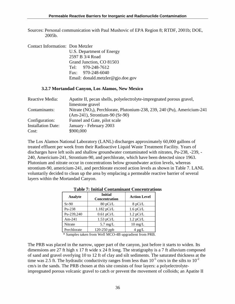
Permeable Reactive Barriers for Inorganic and Radionuclide Contamination
Sources: Personal communication with Paul Mushovic of EPA Region 8; RTDF, 2001b; DOE, 2005b.
Contact Information: Don Metzler U.S. Department of Energy 2597 B 3/4 Road Grand Junction, CO 81503 Tel: 970-248-7612 Fax: 970-248-6040 Email: [email protected]
3.2.7 Mortandad Canyon, Los Alamos, New Mexico
Reactive Media: Apatite II, pecan shells, polyelectrolyte-impregnated porous gravel, limestone gravel
Contaminants: Nitrate (NO3), Perchlorate, Plutonium-238, 239, 240 (Pu), Americium-241 (Am-241), Strontium-90 (Sr-90)
Configuration: Funnel and Gate, pilot scale Installation Date: January - February 2003 Cost: $900,000
The Los Alamos National Laboratory (LANL) discharges approximately 60,000 gallons of treated effluent per week from their Radioactive Liquid Waste Treatment Facility. Years of discharges have left soils and shallow groundwater contaminated with nitrates, Pu-238, -239, 240, Americium-241, Strontium-90, and perchlorate, which have been detected since 1963. Plutonium and nitrate occur in concentrations below groundwater action levels, whereas strontium-90, americium-241, and perchlorate exceed action levels as shown in Table 7. LANL voluntarily decided to clean up the area by emplacing a permeable reactive barrier of several layers within the Mortandad Canyon.
Table 7: Initial Contaminant Concentrations
Analyte Initial
Concentration Action Level
Sr-90 80 pCi/L 8 pCi/L Pu-238 1.182 pCi/L 1.6 pCi/L Pu-239,240 0.61 pCi/L 1.2 pCi/L Am-241 1.53 pCi/L 1.2 pCi/L Nitrate 5.7 mg/L 10 mg/L
Perchlorate 120-250 ppb 4 µg/L * Samples taken from Well MCO-4B upgradient from PRB.
The PRB was placed in the narrow, upper part of the canyon, just before it starts to widen. Its dimensions are 27 ft high x 17 ft wide x 24 ft long. The stratigraphy is a 7 ft alluvium composed of sand and gravel overlying 10 to 12 ft of clay and silt sediments. The saturated thickness at the time was 2.5 ft. The hydraulic conductivity ranges from less than 10-5 cm/s in the silts to 10-2
cm/s in the sands. The PRB chosen at this site consists of four layers: a polyelectrolyte-impregnated porous volcanic gravel to catch or prevent the movement of colloids; an Apatite II
36
Permeable Reactive Barriers for Inorganic and Radionuclide Contamination
layer to treat Pu, Am, and Sr; pecan shells to act as a biobarrier substrate to nitrate and perchlorate, as well as to provide an energy and nutrient source for microbial populations; and a limestone gravel layer to trap anionic species that may not have been caught in the other barriers. Several layers were chosen in order to treat a range of contaminants with dissimilar geochemical properties. The PRB was designed with a 1-day residence time within the biobarrier and a 10year lifespan.
Nitrate and perchlorate have been reduced to below detection limits. Nitrate decreased from an average of 5-12 ppm to 0.01 ppm, whereas the area most concentrated with perchlorate had concentrations decrease from 0.035 to 0.002 ppm. Sr-90 was reduced by 80% in the apatite cell, and by 40% within the bio-barrier, for an overall reduction of an order of magnitude when compared to initial concentrations. Higher concentrations were found at the edges of both cells, and are probably due to varying residence time and saturated thickness of pore water. Concentrations of As and U within and downgradient of the PRB are below their respective action levels. The saturated thickness decreased from 2.5 ft to less than 1 ft by August 2003 due to a drought and a reduction of activities at the Laboratory during 2003. Groundwater flow had ceased towards the end of 2004 as well.
Source: Naftz et al., 2002; ITRC, 2005; LANL, 2004.
Contact Information: Patrick Longmire Los Alamos National Laboratory Group C-INC, MS J514 Los Alamos, NM 87545
Phone: 505-665-1264 Fax: 505-665-4955 E-mail: [email protected]
3.2.8 Rocky Flats Environmental Technology Site (Solar Ponds Plume), Golden, CO
Reactive Media: ZVI and wood chips Contaminants: Nitrate, Uranium Configuration: Reaction Vessels, full scale Installation Date: 1999 Cost: $1,300,000
The Solar Ponds site was used for disposal of products containing nitrates and uranium. The ponds were drained and sludge removed in 1995, but contaminated groundwater had already reached a nearby stream, North Walnut Creek. Initial concentrations of nitrate ranged from 140170 mg/L and uranium was 20-28 pCi/L. Remediation goals required a reduction in nitrate to 100 mg/L and uranium to 10 pCi/L.
A groundwater collection system was installed to meet these goals. The system is about 1,100 ft in length and was placed 20-30 ft bgs, 10 ft of which was keyed into the claystone bedrock. The concrete treatment cell is divided into two sections, the first of which is 32 ft long, 17 ft wide, with reactive media in the lower 10 feet of the cell. It is filled with a mixture of sawdust, leaf
37
Permeable Reactive Barriers for Inorganic and Radionuclide Contamination
mold, and 10% ZVI by weight to aid in the denitrification processes. The second cell is 11 ft long by 17 ft wide and is filled with ZVI to act as a polishing treatment. The two cells can be run separately or simultaneously. Because of the presence of an endangered species and its necessary habitat downhill of the source, the treatment cell was installed directly adjacent to the collection trench, resulting in 11 vertical feet of head difference. This large difference could lead to water migration around, through, or beneath the barrier material, which would decrease treatment efficacy. The distant plume of contaminated groundwater is within the habitat for the endangered species and is contributing to elevated levels at GS-13, a downstream sampling site.
Nitrate and uranium levels in the effluent are generally less than 6 mg/L and 0.2 pCi/L, respectively. This is well below the desired remediation goals. Nitrate levels at GS-13 are much higher, and range from 110-268 mg/L for nitrate and 20.2 to 55.4 pCi/L for uranium. This could be due to the distant plume or from contaminated water migrating around the barrier. Despite this, surface stream samples downgradient of GS-13 are close to the 10 mg/L for nitrate and below 10 pCi/L for uranium.
Water quality results at North Walnut Creek indicate that the PRB is working properly, however corrective actions are being investigated at the GS-13 area where contaminated groundwater may be discharging from a distant plume, or around the barrier.
Sources: RTDF, 2001; USEPA, 2002b; Personal Communication with Craig Cowdery of Rocky Flats Environmental Technology Site on July 29, 2005.
Contact Information: Annette Primrose Kaiser-Hill Co, LLC Rocky Flats Environmental Technology Site 10808 Highway 93, Unit B, Building 116 Golden, CO 80403-8200 Tel: 303- 966-4385 Fax: 303- 966-5180 Email: [email protected]
3.2.9 West Valley Demonstration Site, New York
Reactive Media: Zeolite - Clinoptilolite Contaminants: Strontium-90 Configuration: Pilot Scale Installation Date: 1999
This was the first site developed to use zeolite to promote ion exchange reactions to treat a plume contaminated by Sr-90. Pump-and-treat technologies are the main part of the remediation plan, and the barrier was installed to treat a break-out plume and to study whether a full-scale barrier could be effective as the sole source of treatment in the future. The pilot-scale PRB is 30 ft long x 7 ft wide x 25 ft deep. One foot of pea gravel and a drainage system were emplaced in front of the north wall. Hydrochemical conditions in and around the barrier indicate that the exchange of potassium for strontium is taking place within the PRB, suggesting that the ion exchange process
38
Permeable Reactive Barriers for Inorganic and Radionuclide Contamination
is occurring. In late 2004, concentrations upgradient of the barrier ranged from 10,000-100,000 pCi/L and ranged downgradient from less than 1,000-15,000 pCi/L. Although Sr-90 contamination is still present downgradient of the barrier, levels have been significantly reduced.
The purpose of this pilot-scale test was to study whether or not a 100 ft wall would be effective in capturing the plume, but lack of funding has halted future plans of this nature.
Source: ITRC, 2005; Personal Communication with Moore of WVDS, 2005.
Contact Information: Robert Steiner Phone: 716-942-2870 Email: [email protected]
3.2.10 Y-12 Site, Oak Ridge, Tennessee
Reactive Media: ZVI and peat materials Contaminants: Uranium, Technetium, Nitric acid Configuration: Funnel and Gate, Continuous Trench, full scale Installation Date: 1997 Cost: approximately $1,000,000
The Y-12 Site, operated by DOE, was a major production area for enriched uranium processingand storage, as well as a manufacturing facility for maintenance of nuclear weapons. After the Cold War, the site was downsized. The high enriched uranium was blended into low enriched uranium for commercial use as fuel for nuclear power plants, and the remainder was disposed ofas low-level waste.
Over 2.5 million gallons of hazardous wastes were disposed of each year into disposal ponds north of Bear Creek from 1952 to 1981. All disposal ponds were closed by 1988. The 400 ft2 x 17 ft Y-12 pond was capped in 1983, but leaching has occurred to both the groundwater and surface water, resulting in groundwater plumes of uranium (U), technetium (Tc), and nitrate (NO3
-). There are two areas that were in need of environmental remediation: the Bear Creek and the Upper East Fork Poplar Creek (UEFPC) watersheds. The contaminants of concern in Bear Creek include nitrates, metals, and radionuclides, while the UEFPC is contaminated with metals, specifically mercury and uranium, chlorinated solvents, and radionuclides.
Most groundwater flow occurs at depths less than 100 ft bgs. During rainfall events, the groundwater in the fractured karst geology flows rapidly and discharges to surface streams. Depth to groundwater is 10-15 ft bgs and an unconsolidated aquifer unit is 10-20 ft thick. Two different PRB configurations were chosen as the remediation option to be placed in the unconsolidated aquifer area: 1) a funnel and gate, and 2) a continuous trench.
Pathway 1: The funnel and gate system, installed in December 1997, has been designated as Pathway 1. It is 220 ft in length x 25 ft deep, and is designed to direct groundwater into a concrete vault
39
Permeable Reactive Barriers for Inorganic and Radionuclide Contamination
containing six 55-gallon canisters filled with various combinations of reactive material (i.e., Fe0
and peat moss).
The reactors were stacked vertically for ease of cleaning and replacement of Fe0, although rainwater leaks through the vault and a crane was needed to open the vault doors, which is labor intensive. Guar gum slurry was also added to the trench to prevent slumping, and was later degraded by the addition of an enzyme breaker. The addition of the guar gum has been speculated to have been the cause of an increase in effluent levels of Fe2+. The walls that directed groundwater to the vault cause upwellings on the upgradient side, which required that the system be pumped. A pit downgradient of the vault was created to initiate a more desired groundwater flow to avoid this problem. (Ott, 2001; RTDF, 2000).
Iron plugging, the increase in effluent level of Fe2+, and the leaking caused enough of a problem that the PRB ceased operation.
Pathway 2: A 222 ft long x 2 ft wide x 22-30 ft deep continuous trench was installed in November, 1997. Eighty tons of Fe0 was placed in a 26 ft wide stretch in the middle of the trench, and gravel filled the remaining space. Guar gum was also added to stabilize the walls during excavation. The PRB was installed parallel to the direction of groundwater flow, but perpendicular to the flow of the contaminated plume.
Three years of monthly monitoring showed that U and Tc concentrations decreased. The guar gum may have caused an initial spike in pH due to increased microbial action that has since returned to normal. Its effect also may have caused a decrease in nitrate and sulfate concentrations within or in the area of the influence zone of Fe0 that had a low redox potential (low Eh). (Gu, 1999; RTDF, 2000).
The greatest concentration of uranium in the Fe0 barrier occurred at the shallow, upgradient interface, which suggests that once uranium enters the Fe0 reactive barrier it undergoes either reductive precipitation of relatively insoluble U(IV) species or surface adsorption of U(VI) species on the Fe0 corrosion products (Gu, 1999).
Reduced U(IV) forms oxyhydroxide precipitates in aqueous solution. This and several other mineral precipitates were formed in the Fe0 barrier, such as goethite, ferrous carbonates and sulfides, aragonite, and green rusts. However, sulfate and calcium concentrations have decreased due to precipitation.
Overall, Pathway 2 has shown a decrease in U and Tc concentrations, but because of the reactions with groundwater constituents, the lifespan of the Fe0 wall may be significantly shorter than expected. A current estimate is approximately 15 to 30 years since the time of installation.
Sources: Personal communication with Dr. Gu; RTDF, 2000a; USEPA, 2005a.
40
Permeable Reactive Barriers for Inorganic and Radionuclide Contamination
Contact Information (Formerly): Baohua Gu* Oak Ridge National Laboratory Environmental Sciences Division Oak Ridge, TN 37831-6036 Tel: 423-574-7286 Fax: 423-576-8543 Email: [email protected]
*Through personal communication with Dr. Gu, I was informed that the monitoring has been transferred to Bechtel Jacobs Company LLC, http://www.bechteljacobs.com/
4.0 UPCOMING RESEARCH
4.1 Injection to Treat Hexavalent Chromium (Cr(VI))
Reactive Media: Ferrous iron and sodium hydrosulfite Contaminants: Hexavalent chromium Configuration: Unknown at this time Installation Date: Pilot-scale
This study measured the performance of injections of ferrous iron with sodium hydrosulfite to treat dissolved phase Cr(VI). The study was effective over a two-year period, and the results will be published in the near future.
Source: http://www.epa.gov/ada/research/waste/research_05.pdf
Contact Information: Ralph Ludwig Technical Assistance Technology Transfer Branch USEPA National Risk Management Research Laboratory
919 Kerr Research Drive Ada, OK 74820
Tel: 580-436-8603 Email: [email protected]
4.2 Macalloy Corporation Site, Charleston, South Carolina
Reactive Media: Ferrous iron and sodium hydrosulfite Contaminants: Hexavalent chromium Configuration: Continuous wall Installation Date: Pilot-scale Cost: $25,000
A pile of chromite ore processing solid waste about 20 acre-ft in size is present at the Macalloy Corporation site. Concentrations of dissolved Cr(VI) in the source area are as high as 57 mg/L, and as high as 550 mg/kg for the solid phase. This pilot-scale study is measuring the effectiveness of injected ferrous iron in the presence of sodium hydrosulfite to treat dissolved
41
Permeable Reactive Barriers for Inorganic and Radionuclide Contamination
and solid phase Cr(VI) to detection levels. 4,500-gallons of solution were injected into a single well with over 7.5 ft of screening. The treatment was effective, and a published report is in progress.
Source: http://www.epa.gov/ada/research/waste/research_04.pdf
Contact Information: Ralph Ludwig Technical Assistance Technology Transfer Branch USEPA National Risk Management Research Laboratory
919 Kerr Research Drive Ada, OK 74820
Tel: 580-436-8603 Email: [email protected]
4.3 East Helena Superfund Site, East Helena, Montana
Reactive Media: ZVI Contaminants: Arsenic Configuration: Unknown at this time Installation Date: Proposed Summer 2005
The groundwater at this former metal-smelting facility is contaminated with arsenic at concentrations as high as 5,000 times the new drinking water standard of 10 ppb. Currently, the group is trying to simulate field conditions in the lab in order to develop a pilot-scale barrier for installation in the summer of 2005. After installation, monitoring will occur on a quarterly basis for two years to study the effectiveness of using ZVI within a PRB to treat arsenic, as well as the chemical processes involved in arsenic removal.
Samples studied in the lab found that As solution concentrations increased with decreasing pH, and that As(V) was the most prevalent oxidation state and Scorodite (FeAsO4, 2H2O) is the most prevalent mineral species. The presence of phosphate causes As(III) to oxidize to As(V). “At pH 4, phosphate causes a 10-fold reduction in solution Pb, a 5-fold reduction of solution Cd, and reduces solution concentrations of Cu, Fe, and Al. Zinc solution concentrations are slightly reduced. Solution Pb is also reduced at pH 6” (Impellitteri, 2004).
Sources: http://www.epa.gov/ada/research/waste/research_07.pdf; Impellitteri, 2004.
Contact Information: Rick Wilkin USEPA Office of Research and Development
National Risk Management Research Laboratory GWERD Ada, Oklahoma 74820
Tel: 580-436-8874 Email: [email protected]
42
Permeable Reactive Barriers for Inorganic and Radionuclide Contamination
4.4 Columbia Nitrogen Site, Charleston, South Carolina
Reactive Media: Municipal compost and ZVI Contaminants: Arsenic and heavy metals Configuration: Continuous Wall, pilot scale Installation Date: September 2002
This site is contaminated with pyrite cinders where sulfide oxidation processes have contaminated the groundwater with arsenic and other heavy metals, such as: lead, cadmium, nickel, and zinc. Acid-producing ferrous iron concentrations and a low pH also plague the groundwater and tidal marsh located downstream from the source. A pilot-scale PRB was installed in September 2002 directly in the plume, and measures 30 ft long x 12 ft deep x 6 ft wide. This study will assess the performance of compost/ZVI PRBs in treating arsenic and other heavy metals, the longevity of organic-based carbon systems, and the stability of hydraulic properties over time. Seven rounds of sampling over two years have occurred, and one more year of sampling is predicted before final conclusions can be made.
After 24 months of sampling, there has been an effective removal of the heavy metals, and the pH was raised from <4 to >6. Hydraulic issues are present, and are currently being resolved. A design change may be implemented in the future to remedy the problems faced.
Source: http://www.epa.gov/ada/research/waste/research_01.pdf
Contact Information: Ralph Ludwig Technical Assistance Technology Transfer Branch USEPA National Risk Management Research Laboratory
919 Kerr Research Drive Ada, OK 74820
Tel: 580-436-8603 Email: [email protected]
4.5 Delatte Metals Site, Ponchatoula, Louisiana
Reactive Media: Full-scale: Cow manure and limestone gravel Pilot-scale: Cow manure, wood chips, limestone gravel
Contaminants: Lead and acidity Configuration: Information not available Installation Date: Both installed May 2003
This former battery recycling center has groundwater contaminated with dissolved phase lead and acid that is migrating towards a creek. A pilot-scale PRB consisting of cow manure, wood chips, and limestone gravel, and a full-scale PRB consisting of cow manure and limestone gravel were both installed in May 2003 to treat lead and acidity by microbially-mediated sulfate reduction. During sulfate-reduction processes, carbonate alkalinity is produced to neutralize the pH. This study is looking at the longevity and the stability of hydraulic conductivity over time, and results will be published in the near future.
43
Permeable Reactive Barriers for Inorganic and Radionuclide Contamination
Source: http://www.epa.gov/ada/research/waste/research_02.pdf
Contact Information: Ralph Ludwig Technical Assistance Technology Transfer Branch USEPA National Risk Management Research Laboratory
919 Kerr Research Drive Ada, OK 74820
Tel: 580-436-8603 Email: [email protected]
4.6 Swine CAFO, Oklahoma
Reactive Media: Commercial Hay Contaminants: Nitrates Configuration: Information not available Installation Date: Currently underway
This former swine CAFO was in operation for seven years, and resulted in groundwater contaminated with nitrates and ammonium. An interception trench barrier, above-ground treatment system and a PRB with commercial hay to treat nitrates have been installed. Denitrification is occurring and the PRB is working as expected. Longevity and groundwater flow within and across the barrier are being closely observed. The project period is expected to last from 10/1/03 to 9/30/06.
Source: http://www.epa.gov/ada/research/waste/research_35.pdf
Contact Information: Rick Wilkin USEPA Office of Research and Development
National Risk Management Research Laboratory GWERD Ada, Oklahoma 74820
Tel: 580-436-8874 Email: [email protected]
4.7 Lembach und Schleiera (former dye plant), Wiesbaden, Hesse, Germany
Reactive media: Proposed – Sulphur compounds and ZVI Contaminants: Arsenites Configuration: Proposed – sulphuric reactive zone and a ZVI PRB Installation Date: August 2002 – bench scale and small pilot scale tests
The Lembach und Schleiera abandoned dye plant is located in Wiesbaden, Hesse, Germany, within the Rhine watershed. Significant soil and groundwater contamination has been caused by various arsenic compounds (arsenites, arsenates, partly arsenic trioxide, arsenic pentoxide, and volatile arsenides (secondary)). The contamination was most likely caused by using arsenic
44
Permeable Reactive Barriers for Inorganic and Radionuclide Contamination
oxide as an oxidant over 100 years ago. There is an arsenic plume and an overlapping, heterogeneous, scattered cVOC plume that complicates cleanup.
Contamination in the soil was as high as 56 mg/kg of total Arsenic, and groundwater contamination varies from 27 mg/L at the site to 2 mg/L downgradient of the site. In April 1999, a 10-20 fold increase in arsenic pollution was encountered due to long-lasting, high-water levels increasingly eluating arsenic compounds from the vadose zone. Laboratory work is underway to determine which reactive materials are best suitable for the contamination, and a field-scale application is planned when desired results are obtained from the reactive media. Two possible treatment options are being considered. The first involves a reactive zone of sulphulric compounds to precipitate As, and the second involves a ZVI funnel and gate barrier installed downgradient of the sulphuric reactive zone.
Source: Rubin, 2003.
5.0 LESSONS LEARNED
It was found that the PRBs at four sites encountered serious problems. The Hanford site had Cr(VI) breakthrough in 9 out of 65 wells, possibly caused by increased fracturing, leading to high permeability channels after air rotary drilling was performed. The PRB at the Haardkrom site has not been effectively treating the Cr(VI) plume. This may be caused by an uneven distribution of the plume, which is uncontrollable. Reactivity loss has also been encountered. Severe clogging due to mineral precipitation caused a great loss of permeability and hydraulic conductivity within the PRB at the Cotter Corp. Uranium Mill. This same problem occurred at the Monticello site. Presented in the sections below are lessons learned that are applicable to all sites and will help to enhance performance of PRB technology.
5.1 Site Characterization and PRB Design
• The site must be extensively characterized (specifically hydrogeologically) in order to optimize the effectiveness of the PRB. Geological parameters, such as the aquifer’s composition and hydraulic porosity, need to be considered as well.
• Contaminant properties need to be fully addressed (speciation, geochemical behavior, how they will react under different pHs and redox conditions). Assessing the variability in plume shape and direction over time is also important because it may deviate due to uncontrollable factors, such as recharge, degradation, attenuation, and mixing with other plumes.
• Seasonal variations in groundwater flow may change groundwater migration patterns and need to be taken into account when designing the PRB. The barrier may need to be extended vertically or horizontally.
• PRB construction methods may alter subsurface hydraulic conditions and contaminant migration pathways. These changes should be taken into account when designing the PRB and when measuring performance. Groundwater modeling is recommended to avoid future problems concerning groundwater geochemistry and flow.
• Groundwater velocity will determine residence time within the barrier and directly affects wall design and efficiency.
45
Permeable Reactive Barriers for Inorganic and Radionuclide Contamination
• Diversion of groundwater around a PRB may occur at areas where low gradients and reduced hydraulic conductivity of bedrock fractures are present.
• Batch, column, and lab studies should be performed for an extended period of time to make sure the PRB will function properly in field conditions. This was suggested as a possible downfall in the Monticello barrier.
• The size or scale of a pilot test can influence interpretation of results. • It may be beneficial to plan a design to incorporate an easy replacement of reactive
material. • Using limestone is typically not recommended for highly acidic, Fe-rich waters because
of armoring with Fe(III) oxyhydroxide coatings (Hammarstrom et al., 2002). • A contingency plan should be developed in case the barrier fails design expectations. A
definition of failure should be clearly outlined for all parties involved. • Construction may cause adverse affects on the flow system and contaminant migration
pathways, and should therefore be characterized in the design phase. • When dealing with funnel and gate systems, an inadequate funnel length may lead to
mounding or flow over and under reactive material.
5.2 Installation
• When digging a trench for installation, walls need to be stabilized to prevent slumping or caving in. One can also reduce the length of trench open at any one time to prevent slumping.
• Hydraulic head must be maintained when excavating the trench. • The PRB should be keyed into an impermeable layer or bedrock to prevent underflow.
Care must be taken to not “smear” impermeable layers. If a low permeable layer does not exist, then a hanging wall should be installed. Care also must be taken to ensure that aquifer sediments are not mixed with the reactive media.
• Reactive media needs to be uniformly packed throughout the barrier to prevent preferential paths for contaminants, which may lead to a selective reduction in treatment efficiency of the barrier.
• Adding a pretreatment zone, such as pea gravel, guar, and phosphorous around the barrier, may help to reduce contaminants by precipitation or partial treatment. Pea gravel may precipitate minerals, guar gum increases biological activity, and phosphorous can increase the attenuation rate. This zone also may be used to help increase/decrease groundwater flow.
• Groundwater flow may be induced through the use of a siphon. • Sites where pump-and-treat was previously used need time to return to natural flow
conditions.
5.3 Performance Monitoring
• A range of monitoring wells upgradient, downgradient, and within the PRB at varying depths is recommended to accurately measure performance. Monitoring for geochemical parameters should be performed regularly.
• Use of low-flow, passive sampling techniques is preferred.
46
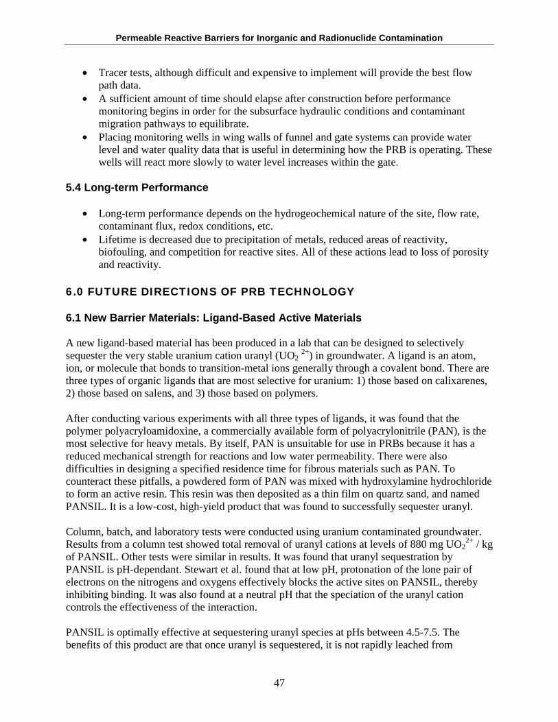
Permeable Reactive Barriers for Inorganic and Radionuclide Contamination
• Tracer tests, although difficult and expensive to implement will provide the best flow path data.
• A sufficient amount of time should elapse after construction before performance monitoring begins in order for the subsurface hydraulic conditions and contaminant migration pathways to equilibrate.
• Placing monitoring wells in wing walls of funnel and gate systems can provide water level and water quality data that is useful in determining how the PRB is operating. These wells will react more slowly to water level increases within the gate.
5.4 Long-term Performance
• Long-term performance depends on the hydrogeochemical nature of the site, flow rate, contaminant flux, redox conditions, etc.
• Lifetime is decreased due to precipitation of metals, reduced areas of reactivity, biofouling, and competition for reactive sites. All of these actions lead to loss of porosity and reactivity.
6.0 FUTURE DIRECTIONS OF PRB TECHNOLOGY
6.1 New Barrier Materials: Ligand-Based Active Materials
A new ligand-based material has been produced in a lab that can be designed to selectively sequester the very stable uranium cation uranyl (UO2
2+) in groundwater. A ligand is an atom, ion, or molecule that bonds to transition-metal ions generally through a covalent bond. There are three types of organic ligands that are most selective for uranium: 1) those based on calixarenes, 2) those based on salens, and 3) those based on polymers.
After conducting various experiments with all three types of ligands, it was found that the polymer polyacryloamidoxine, a commercially available form of polyacrylonitrile (PAN), is the most selective for heavy metals. By itself, PAN is unsuitable for use in PRBs because it has a reduced mechanical strength for reactions and low water permeability. There were also difficulties in designing a specified residence time for fibrous materials such as PAN. To counteract these pitfalls, a powdered form of PAN was mixed with hydroxylamine hydrochloride to form an active resin. This resin was then deposited as a thin film on quartz sand, and named PANSIL. It is a low-cost, high-yield product that was found to successfully sequester uranyl.
Column, batch, and laboratory tests were conducted using uranium contaminated groundwater. Results from a column test showed total removal of uranyl cations at levels of 880 mg UO2
2+ / kg of PANSIL. Other tests were similar in results. It was found that uranyl sequestration by PANSIL is pH-dependant. Stewart et al. found that at low pH, protonation of the lone pair of electrons on the nitrogens and oxygens effectively blocks the active sites on PANSIL, thereby inhibiting binding. It was also found at a neutral pH that the speciation of the uranyl cation controls the effectiveness of the interaction.
PANSIL is optimally effective at sequestering uranyl species at pHs between 4.5-7.5. The benefits of this product are that once uranyl is sequestered, it is not rapidly leached from
47
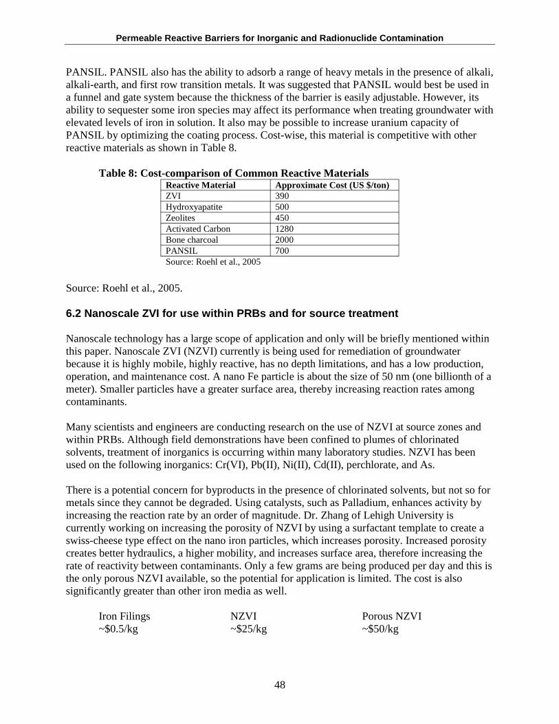
Permeable Reactive Barriers for Inorganic and Radionuclide Contamination
PANSIL. PANSIL also has the ability to adsorb a range of heavy metals in the presence of alkali, alkali-earth, and first row transition metals. It was suggested that PANSIL would best be used in a funnel and gate system because the thickness of the barrier is easily adjustable. However, its ability to sequester some iron species may affect its performance when treating groundwater with elevated levels of iron in solution. It also may be possible to increase uranium capacity of PANSIL by optimizing the coating process. Cost-wise, this material is competitive with other reactive materials as shown in Table 8.
Table 8: Cost-comparison of Common Reactive Materials Reactive Material Approximate Cost (US $/ton) ZVI 390 Hydroxyapatite 500 Zeolites 450 Activated Carbon 1280 Bone charcoal 2000 PANSIL 700 Source: Roehl et al., 2005
Source: Roehl et al., 2005.
6.2 Nanoscale ZVI for use within PRBs and for source treatment
Nanoscale technology has a large scope of application and only will be briefly mentioned within this paper. Nanoscale ZVI (NZVI) currently is being used for remediation of groundwater because it is highly mobile, highly reactive, has no depth limitations, and has a low production, operation, and maintenance cost. A nano Fe particle is about the size of 50 nm (one billionth of a meter). Smaller particles have a greater surface area, thereby increasing reaction rates among contaminants.
Many scientists and engineers are conducting research on the use of NZVI at source zones and within PRBs. Although field demonstrations have been confined to plumes of chlorinated solvents, treatment of inorganics is occurring within many laboratory studies. NZVI has been used on the following inorganics: Cr(VI), Pb(II), Ni(II), Cd(II), perchlorate, and As.
There is a potential concern for byproducts in the presence of chlorinated solvents, but not so for metals since they cannot be degraded. Using catalysts, such as Palladium, enhances activity by increasing the reaction rate by an order of magnitude. Dr. Zhang of Lehigh University is currently working on increasing the porosity of NZVI by using a surfactant template to create a swiss-cheese type effect on the nano iron particles, which increases porosity. Increased porosity creates better hydraulics, a higher mobility, and increases surface area, therefore increasing the rate of reactivity between contaminants. Only a few grams are being produced per day and this is the only porous NZVI available, so the potential for application is limited. The cost is also significantly greater than other iron media as well.
Iron Filings NZVI Porous NZVI ~$0.5/kg ~$25/kg ~$50/kg
48
Permeable Reactive Barriers for Inorganic and Radionuclide Contamination
The cost estimate is based on predicted costs because the porous NZVI is not commercially available.
Source: Zhang, 2005
6.3 Phytoremediation as a Polishing Technique
Phytoremediation uses plants to remediate groundwater, soils, and sediments contaminated with organic and inorganic pollution through a variety of methods, including: degradation, sorption, translocation, transpiration, and rhizosphere-enhanced degradation of contaminants (Compton et al., 2003). This cleanup technique is cost-effective, promotes restoration, and is aesthetically pleasing. Phytoremediation works best at low to moderate concentrations (high concentrations may be phytotoxic), and is often part of a treatment train due to the length of time required for cleanup. Plants must be maintained during their lifespan to ensure contaminant cleanup.
Dr. Judy Sophianopoulos from U.S. EPA Region 4-Athens is currently conducting a pilot-scale study at the Columbia Nitrogen Site (See Section 4.4), which is contaminated with arsenic and other metals in the soil. The Chinese Brake Fern is being used to accumulate As within the shallow ground surface while a PRB has been installed to treat the groundwater. The ferns were planted in 2003, and it was found that over the period of a year, the As concentrations within the soil decreased from 670 mg/kg to 280 mg/kg as shown in Table 9. It is evident that the ferns were accumulating As, and samples show that As increased from 3 mg/kg to 2,000 mg/kg within the fern roots. The bioconcentration factor increased from 2.8 to 7.1 during May 03 to April 04.
Table 9: Sampling Results at Columbia Nitrogen Site
Sample Date Sample As
(mg/kg) Pb
(mg/kg) Hg
(mg/kg)
5/14/2003 Soil 670 1,100 2 Fern 3 0.56 0.08
6/17/2003 Soil 280 1,300 2.2 Fern 89 170 0.33
9/10/2003 Soil 220 1,100 1.9 Fern 740 22 0.13
12/2/2003 Soil 282 1,300 2.4 Fern 790 38 0.16
3/11/2004 Soil Not Reported Not Reported Not Reported Fern 65 76 0.37
4/29/2004 Soil 280 1,300 2.2
Fern 2000 20 0.07
A new set of ferns were planted in June 2005, and experimental work for the phytoremediation portion of the project is expected to be completed by the end of Summer 2005.
6.4 Electrokinetic Techniques
Electrokinetics is not a new field within geoenvironmental engineering, but its use in combination with a PRB has not been sufficiently researched within coarse-grained soils to
49
Permeable Reactive Barriers for Inorganic and Radionuclide Contamination
determine its applicability under these conditions. Electrokinetics involves the application of a low density current to contaminated soil via electrodes placed in the soil in order to mobilize contaminants towards the electrode reservoirs. Water or chemical solutions can be added to enhance movement. An electric field can cause:
• Electroosmosis – the movement of liquid relative to a charged stationary surface; suitable for fine-grained soils.
• Electromigration – transport of charged ions in solution; suitable for fine- and coarse-grained soils.
• Electrophoresis – movement of charged particles relative to a stationary fluid; suitable for coarse-grained soils.
The contaminants are concentrated in solution around the electrodes and treated via electroplating or precipitation at electrodes, use of ion exchange resins, or by pumping and treating at the surface.
Several small-scale and bench-scale laboratory experiments were conducted using an electrokinetic fence upgradient of a PRB to reduce the amount of groundwater constituents that may otherwise potentially cause clogging within the barrier.
It was found that the bulk of the charged species were prevented from moving past the electrodes. Within the experiment, a field strength of 100 V/m was needed to hold back the monovalent and divalent ions when the hydraulic gradient was 0.001. Cations were also held back through precipitation at the cathodes. Retention of these charged ions results in a small loss of porosity and little hydraulic change within the soils. The retention of groundwater constituents upgradient of a barrier will slow the clogging factor, and theoretically increase the lifespan of the PRB. The applicability of these results for field-scale studies seems promising. (CRA, 2000; Roehl et al., 2005).
Source: Roehl et al., 2005.
7.0 CONCLUSION
Permeable reactive barriers have been increasingly used throughout the world as a passive, in situ, cost-effective treatment option for both organic and inorganic contamination. To effectively utilize this technology, it is imperative that the site be fully characterized and understood before implementation. The case studies provided here show evidence that PRBs can be successfully employed to address a range of contaminants.
This passive treatment option will only be feasible if there is no urgent need to address a contaminant threat, because it may take several decades for cleanup to be attained. Due to the long term nature of cleanups utilizing PRBs, and because there are few studies that have looked at the long term results of PRBs, it is important to determine their long-term performance. At present, no one has been able to say, without a doubt, that a reactive barrier will perform efficiently for the lifetime of the contaminants. However, many studies have been, and are currently being conducted to assess the long-term performance of these walls. A lack of publicly
50
Permeable Reactive Barriers for Inorganic and Radionuclide Contamination
available information may also hamper the ability to determine barrier performance. Most problems that have arisen during the lifespan of the technology stem from a lack of understanding of hydraulic properties of the local and regional aquifer systems. As the oldest barriers age and data on their effectiveness are collected, there will be a better understanding on how this technology will perform over time.
Since 2001, the number of sites using PRBs for metals and radionuclides has increased. The first PRBs for these contaminants were installed in the mid-nineties (Cyprus AMAX, Nickel Rim, Bodo Canyon, and Universal Forest Products). There are now approximately 30-some sites known to the author, which is over a 600% increase in use since 2001. Most are located within the USA, but there is a small number installed abroad. Research and field data have shown that PRBs are practical and effective. The increase in available reactive media has also helped to open up the field. In 1994, granular zero valent iron was most prevalently used, but now additional compounds such as iron filings, iron powder, and nanoscale iron are available to provide a more reactive and targeted media. Other reactive media also have been recently introduced and continued performance monitoring of these materials will lead to a better understanding and application. Advances in construction techniques have allowed for deeper, thinner, and more exact placement of the barriers as well.
The decision to use a PRB is entirely site-specific. The time-frame, contaminants of concern, site characteristics, availability and suitability of the reactive material, and hydrogeological characteristics are all important considerations. Permeable reactive barriers are not universally applicable, but when site characteristics are suitable and the contaminant removal method is available, they have been shown to be an effective treatment option. Further research into the long-term performance of the barriers currently in operation, as well as research on new reactive materials for contaminants, will help to further the understanding and applicability of such technologies.
51
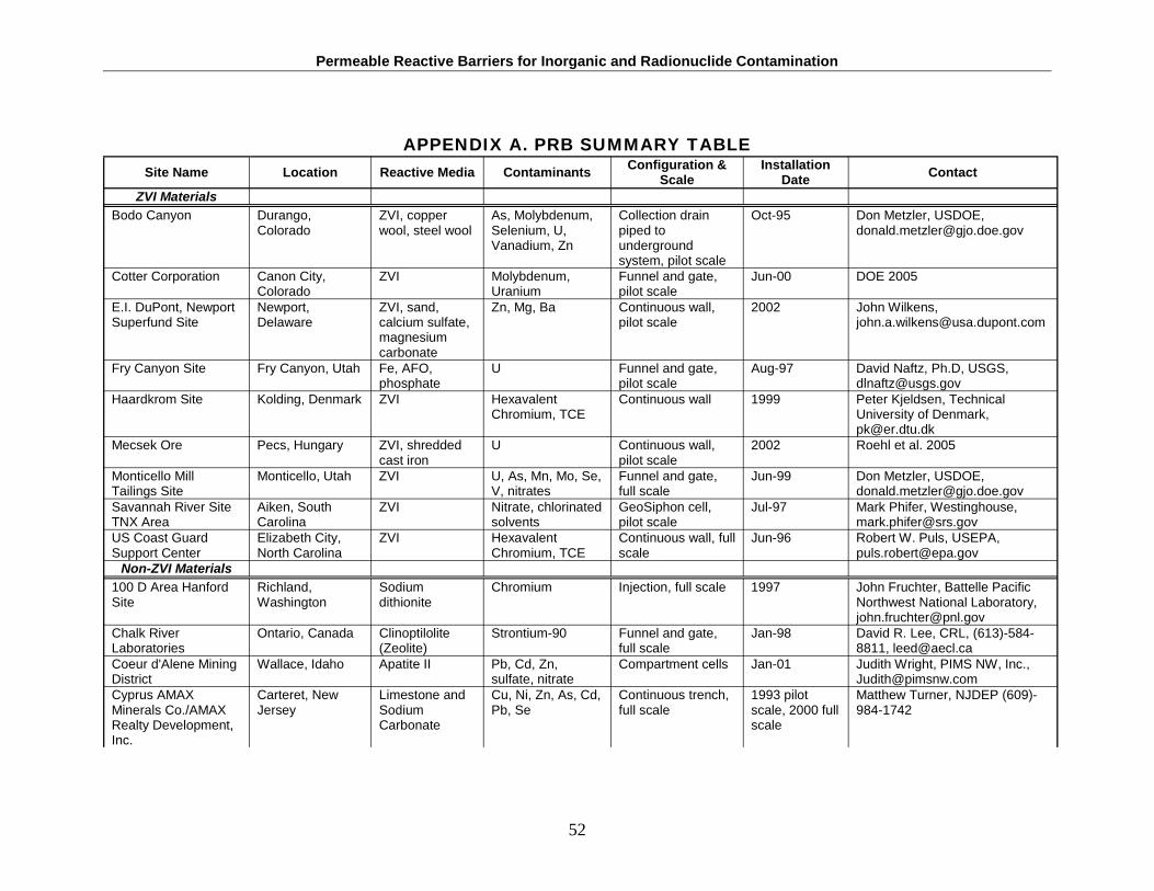
Permeable Reactive Barriers for Inorganic and Radionuclide Contamination
APPENDIX A. PRB SUMMARY TABLE
Site Name Location Reactive Media Contaminants Configuration & Scale
Installation Date Contact
ZVI Materials Bodo Canyon Durango, ZVI, copper As, Molybdenum, Collection drain Oct-95 Don Metzler, USDOE,
Colorado wool, steel wool Selenium, U, Vanadium, Zn
piped to underground system, pilot scale
Cotter Corporation Canon City, Colorado
ZVI Molybdenum, Uranium
Funnel and gate, pilot scale
Jun-00 DOE 2005
E.I. DuPont, Newport Newport, ZVI, sand, Zn, Mg, Ba Continuous wall, 2002 John Wilkens, Superfund Site Delaware calcium sulfate, pilot scale [email protected]
magnesium carbonate
Fry Canyon Site Fry Canyon, Utah Fe, AFO, phosphate
U Funnel and gate, pilot scale
Aug-97 David Naftz, Ph.D, USGS, [email protected]
Haardkrom Site Kolding, Denmark ZVI Hexavalent Continuous wall 1999 Peter Kjeldsen, Technical Chromium, TCE University of Denmark,
[email protected] Mecsek Ore Pecs, Hungary ZVI, shredded
cast iron U Continuous wall,
pilot scale 2002 Roehl et al. 2005
Monticello Mill Monticello, Utah ZVI U, As, Mn, Mo, Se, Funnel and gate, Jun-99 Don Metzler, USDOE, Tailings Site V, nitrates full scale [email protected] Savannah River Site Aiken, South ZVI Nitrate, chlorinated GeoSiphon cell, Jul-97 Mark Phifer, Westinghouse, TNX Area Carolina solvents pilot scale [email protected] US Coast Guard Elizabeth City, ZVI Hexavalent Continuous wall, full Jun-96 Robert W. Puls, USEPA, Support Center North Carolina Chromium, TCE scale [email protected]
Non-ZVI Materials 100 D Area Hanford Richland, Sodium Chromium Injection, full scale 1997 John Fruchter, Battelle Pacific Site Washington dithionite Northwest National Laboratory,
[email protected] Chalk River Ontario, Canada Clinoptilolite Strontium-90 Funnel and gate, Jan-98 David R. Lee, CRL, (613)-584-Laboratories (Zeolite) full scale 8811, [email protected] Coeur d'Alene Mining Wallace, Idaho Apatite II Pb, Cd, Zn, Compartment cells Jan-01 Judith Wright, PIMS NW, Inc., District sulfate, nitrate [email protected] Cyprus AMAX Carteret, New Limestone and Cu, Ni, Zn, As, Cd, Continuous trench, 1993 pilot Matthew Turner, NJDEP (609)-Minerals Co./AMAX Jersey Sodium Pb, Se full scale scale, 2000 full 984-1742 Realty Development, Carbonate scale Inc.
52
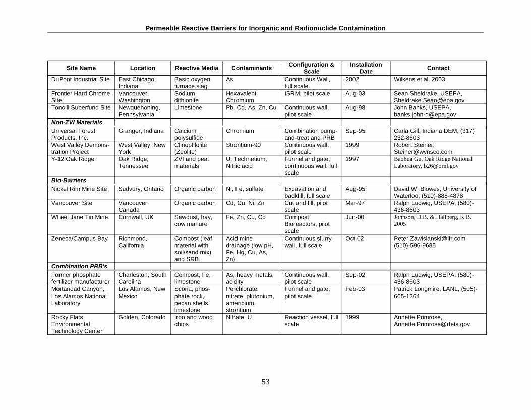
Permeable Reactive Barriers for Inorganic and Radionuclide Contamination
Site Name Location Reactive Media Contaminants Configuration & Scale
Installation Date Contact
DuPont Industrial Site East Chicago, Basic oxygen As Continuous Wall, 2002 Wilkens et al. 2003 Indiana furnace slag full scale
Frontier Hard Chrome Vancouver, Sodium Hexavalent ISRM, pilot scale Aug-03 Sean Sheldrake, USEPA, Site Washington dithionite Chromium [email protected] Tonolli Superfund Site Newquehoning, Limestone Pb, Cd, As, Zn, Cu Continuous wall, Aug-98 John Banks, USEPA,
Pennsylvania pilot scale [email protected] Non-ZVI Materials Universal Forest Granger, Indiana Calcium Chromium Combination pump- Sep-95 Carla Gill, Indiana DEM, (317) Products, Inc. polysulfide and-treat and PRB 232-8603 West Valley Demons- West Valley, New Clinoptilolite Strontium-90 Continuous wall, 1999 Robert Steiner, tration Project York (Zeolite) pilot scale [email protected] Y-12 Oak Ridge Oak Ridge, ZVI and peat U, Technetium, Funnel and gate, 1997 Baohua Gu, Oak Ridge National
Tennessee materials Nitric acid continuous wall, full Laboratory, [email protected] scale
Bio-Barriers Nickel Rim Mine Site Sudvury, Ontario Organic carbon Ni, Fe, sulfate Excavation and Aug-95 David W. Blowes, University of
backfill, full scale Waterloo, (519)-888-4878 Vancouver Site Vancouver,
Canada Organic carbon Cd, Cu, Ni, Zn Cut and fill, pilot
scale Mar-97 Ralph Ludwig, USEPA, (580)-
436-8603 Wheel Jane Tin Mine Cornwall, UK Sawdust, hay, Fe, Zn, Cu, Cd Compost Jun-00 Johnson, D.B. & Hallberg, K.B.
cow manure Bioreactors, pilot 2005 scale
Zeneca/Campus Bay Richmond, Compost (leaf Acid mine Continuous slurry Oct-02 Peter [email protected] California material with
soil/sand mix) and SRB
drainage (low pH, Fe, Hg, Cu, As, Zn)
wall, full scale (510)-596-9685
Combination PRB's Former phosphate Charleston, South Compost, Fe, As, heavy metals, Continuous wall, Sep-02 Ralph Ludwig, USEPA, (580)-fertilizer manufacturer Carolina limestone acidity pilot scale 436-8603 Mortandad Canyon, Los Alamos, New Scoria, phos- Perchlorate, Funnel and gate, Feb-03 Patrick Longmire, LANL, (505)-Los Alamos National Mexico phate rock, nitrate, plutonium, pilot scale 665-1264 Laboratory pecan shells, americium,
limestone strontium Rocky Flats Golden, Colorado Iron and wood Nitrate, U Reaction vessel, full 1999 Annette Primrose, Environmental chips scale [email protected] Technology Center
53
Permeable Reactive Barriers for Inorganic and Radionuclide Contamination
REFERENCES
AMAX Realty Development, Inc. January 2005. Cyprus AMAX Report 05-107 Results of Sampling Selected Wells December 2004.
Blowes, D.W.; Ptacek, C.J.; Benner, S.G.; McRae, C.W.T.; Bennett, T.A.; Puls, R.W. 2000. “Treatment of Inorganic Contaminants Using Permeable Reactive Barriers.” Journal of Contaminant Hydrology, 45, 123-137.
Conestoga-Rovers & Associates (CRA). April 2000. Innovative Technology Group Vol.2, No. 4.
Doerr, N.A.; Ptacek, C.J.; Blowes, D.W. Effects of a reactive barrier and aquifer geology on metal distribution and mobility in a mine drainage impacted aquifer. Journal of Contaminant Hydrology 78 (2005) 1-25.
Energy Web. 2002. Mining Sector: Jargon Buster: Zeolites. http://www.energyweb.net/mining/jargon/default.asp?u_letter=z.
Fruchter, John. July 15, 2005. Personal Communication via email.
Godage, W.D.; Gavaskar, A.R.; Gibbs, J.T.; Means, J.L. 2000. “In Situ Remediation of Mercury-Impacted Groundwater: Laboratory and Field Evaluation.” Case Studies in the Remediation of Chlorinated and Recalcitrant Compounds. Battelle Press, Richmond, VA.
Gu, Baohua. 1999. “Uranium (VI) Metal by Zero-Valent Iron Metal.” http://www.esd.ornl.gov/~b26/uranium.htm
Hammarstrom, J.M.; Sibrell, P.L.; Belkin, H.E. 2003. Characterization of limestone reacted with AMD in a pulsed limestone bed treatment system at the Friendship Hill National Historic Site, PA, USA. Applied Geochemistry 18 (2003) 1705-1721.
Hemsi, P.S.; Shackelford, C.D.; Figueroa, L.A. 2005. “Modeling the Influence of Cecomposing Organic Solids on Sulfate Reduction Rates for Iron Precipitation.” Environmental Science & Technology, 39, 3215-3225.
Impellitteri, C.A. October 26, 2004. Effects of pH and phosphate on metal distribution with emphasis on As speciation and mobilization in soils from a lead smelting site. Science of the Total Environment 345 (2005) 175 – 190.
International Business Communications. 1999. “Subsurface Barrier Technologies.” IBC Environmental Technology Symposium Proceedings. Scottsdale, Arizona. February 1-2.
Interstate Technology and Regulatory Cooperation (ITRC). 1997. Emerging Technologies for the Remediation of Metals in Soils: In-Situ Stabilization/ Inplace Inactivation.
54
Permeable Reactive Barriers for Inorganic and Radionuclide Contamination
Interstate Technology and Regulatory Cooperation (ITRC). February 2005. Permeable Reactive Barriers: Lessons Learned/New Directions. http://www.itrcweb.org/Documents/PRB-4.pdf
Johnson, D.B. & Hallberg, K.B. 2005. Science of the Total Environment 338 (2005) 81-93.
Keller Ground Remediation. http://www.keller-ge.co.uk/index.php?page=43
Kentucky State. Dissolved Oxygen. http://www.state.ky.us/nrepc/water/wcpdo.htm
Lee, D.R.; Hartwig, D.S. 2001. Zeolite prevents discharge of Strontium-90-contaminated groundwater. Atomic Energy of Canada Limited, Chalk River Laboratories, Chalk River, Ontario.
Los Alamos National Laboratory. 2004. Demonstration of a Multi-Layered Permeable Reactive Barrier in Mortandad Canyon at Los Alamos National Laboratory. http://pearl1.lanl.gov/external/INC/geochemistry/strietelmeier/LANL-MultiLayerPRBreport.pdf
Max-Planck Institut. 2000. Heavy Metal Contamination and its Consequences. http://www.mpimp-golm.mpg.de/kraemer/forschung/metal-contamination-e.html
Monday Creek. 2001. Watershed Glossary. http://www.mondaycreek.org/glossary.html
Moore. July 18, 2005. Personal Communication via email.
Moyers, J.R.; Nichols, J.D.; Whitlock, I. 1997. “Disadvantages of Pump and Treat Remediation.” http://ewr.cee.vt.edu/environmental/teach/gwprimer/ Pumptrt/Pumptrt.html
Mushovic, Paul. July 5, 2005. Personal Communication via email.
Naftz, D.L.; Morrison, S.J.; Davis, J.A.; Fuller, C.C. 2002. Handbook of Groundwater Remediation Using Permeable Reactive Barriers: Applications to Radionuclides, Trace Metals, and Nutrients. Academic Press, New York.
Nanavut Wildlife Health Assessment Project. 2005. Glossary of Scientific Terms. http://www.trentu.ca/nwhp/glossary.shtml
Nordstrom, D.K. 2000. Aqueous Redox Chemistry and the Behavior of Iron in Acid Mine Waters. USGS. http://water.usgs.gov/nrp/proj.bib/Publications/ nordstrom_epa.pdf
Ott, Nichole. 2001. Permeable Reactive Barriers for Inorganics. Clu-in.org.
55
Permeable Reactive Barriers for Inorganic and Radionuclide Contamination
Pennsylvania Department of Environmental Protection (PADEP). “Reclaim PA Home Page.” http://www.dep.state.pa.us/dep/deputate/minres/reclaimpa/reclaimpahome.htm
Phifer, M.A.; Nichols, R.L.; Sappington, F.C.; Steimke, J.L.; Jones, W.E. 2005. GeoSiphon groundwater remediation system hydraulics. Westinghouse Savannah River Company
Remco Engineering. 1981. Ion Exchange: Basic Concepts. http://www.remco.com/ix.htm
Roehl, K.E.; Czurda, K.; Meggyes, T.; Simon, F.; Stewart, D.I. 2005. Long-term Performance of Permeable Reactive Barriers. Elsevier, New York.
Remediation Technologies Development Forum (RTDF). Permeable Reactive Barriers Installation Profiles. http://www.rtdf.org/public/permbarr/prbsumms/ default.cfm
Remediation Technologies Development Forum (RTDF). Permeable Reactive Barriers Team. November 6-7, 2002 Meeting Summary. http://www.rtdf.org/ public/permbarr/minutes/110702/summary.html
Remediation Technologies Development Forum (RTDF). January 14, 2000a. Y-12 Oak Ridge Site, Tennessee PRB Profile. http://www.rtdf.org/public/permbarr/PRBSUMMS/profile.cfm?mid=45
Remediation Technologies Development Forum (RTDF). January, 2000b. Nickel Rim Mine Site, Sudbury, Ontario, CA PRB Profile. http://www.rtdf.org/public/ permbarr/PRBSUMMS/profile.cfm?mid=41
Remediation Technologies Development Forum (RTDF). June 2001a. Rocky Flats Environmental Technology Site (Solar Ponds Plume) PRB Profile. http://www.rtdf.org/public/permbarr/PRBSUMMS/profile.cfm?mid=87
Remediation Technologies Development Forum (RTDF). July 2001b. Former Mill Site, Monticello, Utah PRB Profile. http://www.rtdf.org/public/permbarr/PRBSUMMS/profile.cfm?mid=83
Remediation Technologies Development Forum (RTDF). July 2001c. Bodo Canyon, Durango, CO. http://www.rtdf.org/public/permbarr/PRBSUMMS/profile.cfm?mid=82
Remediation Technologies Development Forum (RTDF) May 2001d. Chalk River Laboratories, Ontario, Canada. http://www.rtdf.org/public/permbarr/prbsumms/profile.cfm?mid=72
Rubin. 2003. Wiesbaden Site, Hesse, Germany. http://www.rubin-online. de/english/projects/rubinprojects/wiesbaden/index.html
56

Permeable Reactive Barriers for Inorganic and Radionuclide Contamination
Schad; Gratwohl. 1998. “Funnel and Gate Systems for In-Situ Treatment of Contaminated Groundwater at Former Manufactured Gas Plant Sites.” Treatment Walls and Permeable Reactive Barriers, Vol. 229, pp 56-65, NATO CCMS, Vienna.
Simon, F.; Meggyes, T. 2000. Removal of Organic and Inorganic Pollutants from Groundwater Using Permeable Reactive Barriers. Land Contamination & Reclamation, Vol. 8, Issue 2, 103-116.
Smyth, D. J.A.; Blowes, D.W.; McRae, C. W.T.; Ptacek, C.J.; Spink, L. Undated Material. 2005. The Removal of Arsenic from Groundwater Using Permeable Reactive Barriers (PRBs). http://www.containment.fsu.edu/cd/content/pdf/111.pdf
TechKnow. 2000. GeoSiphon cells. http://www.techknow.org/search/remediation/RemDetail.cfm?TechID=304
University of Waterloo, Department of Earth Sciences. 2001. Permeable Reactive Barriers. http://www.science.uwaterloo.ca/research/ggr/PermeableReactiveBarriers/PRBforAMD/PRBforAMD.html
U.S. Department of Energy (DOE). Reactive Materials Development: Zero-Valent Iron (ZVI). http://www.lm.doe.gov/perm-barr/materials/materials.htm
U.S. Department of Energy (DOE). September 1996. Long-Term Surveillance Plan for the Bodo Canyon Disposal Site, Durango, Colorado. Report Number: DOE/AL/62350-77. http://www.lm.doe.gov/documents/sites/co/dur_d/ltsp/dur_toc.htm
U.S. Department of Energy (DOE). April 2005a. Performance Assessment and Recommendations for Rejuvenation of a Permeable Reactive Barrier: Cotter Corporation’s Canon City, Colorado, Uranium Mill. Report Number: DOE–LM/GJ816– 2005. http://www.lm.doe.gov/documents/4_land/ESL_reports/canon_city_prb.pdf
U.S. Department of Energy (DOE). February 2005b. Variation in Hydraulic Conductivity over Time at the Monticello Permeable Reactive Barrier. http://www.lm.doe.gov/documents/4_ land/ESL_reports/monticello_prb.pdf
U.S. Environmental Protection Agency (USEPA). September 1998. Permeable Reactive Barrier Technologies for Contaminant Remediation. http://clu-in.org/download/ rtdf/prb/reactbar.pdf
U.S. Environmental Protection Agency (USEPA). January 2001a. Fact Sheet: Drinking Water Standards for Arsenic. http://www.epa.gov/safewater/ars/ars_rule_ factsheet.html
U.S. Environmental Protection Agency (USEPA). April 2001b. A Citizens Guide to Permeable Reactive Barriers. EPA Document Number 542-F-01-005. http://www.clu-in.org/download/citizens/citprb.pdf.
57
Permeable Reactive Barriers for Inorganic and Radionuclide Contamination
U.S. Environmental Protection Agency (USEPA). May 2001c. EPA Superfund: Explanation of Significant Differences. E.I. DuPont De Nemours & Co., Inc. (Newport Pigment Plant Landfill). EPA ID: DED980555122 OU 01 Newport, DE, 05/18/2001.
U.S. Environmental Protection Agency (USEPA). May 2002a. Cost and Performance Report: Permeable Reactive Barriers Interim Summary Report.
U.S. Environmental Protection Agency (USEPA). July 2002b. First Five-Year Review Report for Rocky Flats Environmental Technology Site Golden, Colorado. http://www.epa.gov/superfund/sites/fiveyear/f02-08004.pdf
U.S. Environmental Protection Agency (USEPA). August 2003a, Capstone Report on the Application, Monitoring, and Performance of Permeable Reactive Barriers for Ground-Water Remediation: Volume 1 – Performance Evaluations at Two Sites. EPA/600/R-03/045a
U.S. Environmental Protection Agency (USEPA). August 2003b, Capstone Report on the Application, Monitoring, and Performance of Permeable Reactive Barriers: Volume 2 – Long-Term Monitoring of PRBs: Soil and Ground Water Sampling. EPA/600/R-03/045b
U.S. Environmental Protection Agency (USEPA). January 2004a. Frontier Hard Chrome, Inc. In Situ Redox Manipulation Permeable Reactive Barrier Emplacement: Final Report. http://yosemite.epa.gov/R10/CLEANUP.NSF/0/9e8d464bb0780587882565280056f5d1?OpenDocument
U.S. Environmental Protection Agency (USEPA). November 2004b. Radionuclides. http://www.epa.gov/radiaion/radionuclides
U.S. Environmental Protection Agency (USEPA). June 27, 2005a. Superfund Site Progress Profile: Oak Ridge Reservation. http://cfpub1.epa.gov/super cpad/cursites/csitinfo.cfm?id=0404152
U.S. Environmental Protection Agency (USEPA). June 27, 2005b. Superfund Site Progress Profile Tonolli Corp. http://cfpub1.epa.gov/supercpad/cursites/ csitinfo.cfm?id=0301087
Wilkens, J.; Shoemaker, S.H.; Bazela, W.B.; Egler, A.P.; Sinha, R.; Bain, J.G. 2003. Arsenic Removal from Groundwater Using a BOF Slag at the DuPont East Chicago (IN) Site. RTDF PRB Action Teem Meeting, October 16, 2003. http://rtdf.org/PUBLIC/permbarr/minutes/101603/pdf/q_wilkens.pdf
Wright, J.; Stasney, B.; Conca, J.L. 2004. An Apatite II Permeable Reactive Barrier to Remediate Groundwater Containing Zn, Pb, and Cd. Submitted to Journal of Contaminant Hydrology, June 2004.
58
Permeable Reactive Barriers for Inorganic and Radionuclide Contamination
Zhang, W. Presentation on Monday July 18, 2005 at 11:30 – 1:00 in EPA Ariel Rio South Building, Washington, DC.
59