ost and performance report - frtr and performance report permeable reactive barriers interim summary...
TRANSCRIPT
COST ANDPERFORMANCE
REPORT
Permeable Reactive Barriers Interim Summary Report:Permeable Reactive Barriers
Using Iron With a Bulking Agentas a Reactive Media
May 2002
U.S. Environmental Protection AgencyOffice of Solid Waste and Emergency ResponseTechnology Innovation Office

Permeable Reactive Barriers Interim Summary Report:Permeable Reactive Barriers Using Iron With a Bulking Agent as a Reactive Media
U.S. Environmental Protection AgencyOffice of Solid Waste and Emergency Response 1 May 2002Technology Innovation Office
Introduction
This report provides an interim summary of information of eight projects (seven full-scale andone pilot-scale) using permeable reactive barriers (PRBs) where iron with a bulking agent wasused as a reactive media for treatment of contaminated groundwater. A PRB contains orcreates a reactive treatment zone oriented to intercept and remediate a contaminant plume.Contaminants are removed from the groundwater flow system by physical, biological, orchemical processes (EPA, 2002a).
Table 1 summarizes available information about the eight projects, including year of installation,specific contaminants treated, PRB configuration and wall dimensions, installation method,installation depth, reactive media used, and cost data. Each of the PRBs was installed between1995 and 2000.
Information about seven of the eight projects was obtained from Installation Profiles published bythe Remediation Technologies Development Forum1 (RTDF), and which are available online atwww.rtdf.org. Information on the additional project (Lake City Army Ammunition Plant) wasobtained from the U.S. Environmental Protection Agency (EPA) Remediation andCharacterization Innovative Technologies web site at <www.EPAReachIT.org> and follow-upcommunication with the EPA project manager for the site. The eight projects are:
Full-Scale Projects
• F.E. Warren Air Force Base – Cheyenne, Wyoming
• Lake City Army Ammunition Plant – Independence, Missouri
• Rocky Flats Environmental Technology, Solar Ponds Plume – Golden, Colorado
• Rocky Flats Environmental Technology, East Trenches Site – Golden, Colorado
• Seneca Army Depot – Romulus, New York
• Somersworth Sanitary Landfill – Somersworth, New Hampshire
• Watervliet Arsenal – Watervliet, New York
Pilot-Scale Project
• Bodo Canyon – Durango, Colorado
Each of the PRB projects profiled in this report used iron (zero-valent iron or Fe0) combined witha bulking agent, such as sand, wood chips, or copper or steel wool.
Iron was one of the first reactive media used in PRBs for treating groundwater contaminated withchlorinated volatile organic compounds (VOC’s), and many PRBs have reactive zones
1 The RTDF has an ongoing effort to track PRB projects in the field and to periodically update information about those projects.When this case study was prepared, RTDF had published Installation Profiles for 47 PRB projects. The RTDF selects PRBprojects for its web site based on availability of information, and includes mostly sites that have been in the field for relativelylonger periods of time, as well as sites with relatively greater amounts of information. While not a representative sample of sites,the projects tracked by the RTDF provide a cross-section of the general types of projects in which PRBs have been installed. Inaddition, the RTDF is performing a longer-term review of project performance, and the data available for this case study is asnapshot of data available to date.

Permeable Reactive Barriers Interim Summary Report:Permeable Reactive Barriers Using Iron With a Bulking Agent as a Reactive Media
U.S. Environmental Protection AgencyOffice of Solid Waste and Emergency Response 2 May 2002Technology Innovation Office
containing only iron as a reactive media. Recently, PRBs have been installed using a reactivezone consisting of iron combined with a bulking agent. Bulking agents have been combined withiron for several reasons, including improving groundwater flow conditions within the reactivezone, treatment of additional contaminants not addressed by iron alone, and reducing projectcost.
Summary of PRB Projects Using Iron with Bulking Agents
Contaminants Treated
Six of the eight PRB projects were used to treat groundwater contaminated primarily withchlorinated VOCs, including tetrachloroethene (PCE), trichloroethene (TCE), dichloroethene(DCE), methylene chloride, vinyl chloride (VC), carbon tetrachloride, and chloroform. Oneproject at the Rocky Flats Environmental Technology (Rocky Flats) site (Solar Ponds Plume)and the Bodo Canyon site treated groundwater contaminated with uranium, as well as otherinorganic contaminants. Nitrate was present in groundwater at the Solar Ponds Plume site,while the Bodo Canyon site also was contaminated with such metals as arsenic, molybdenum,selenium, vanadium and zinc.
PRB Configuration
All eight projects employed either a continuous reactive wall (five sites) configuration or areaction vessel (three sites) configuration. An example configuration of the continuous wallinstalled at the Somersworth Landfill is included in this report as Figure 1. The continuousreactive wall configuration was intended to intercept the flow of contaminated groundwater andtreat it without affecting groundwater flow. In the reaction vessel configuration, groundwater wasrouted via natural or engineered preferential pathways to a subsurface reaction vessel. Waterflow through a reaction vessel was designed to be perpendicular to groundwater flow, ratherthan the parallel flow that is characteristic of the continuous reactive wall configuration. Thefunnel and gate PRB configuration, which is used to capture groundwater over a large area anddirect it to a smaller reactive zone, was not used in these projects.
PRB Installation Method
Six of the eight PRBs were installed using supported excavation technologies such as slurries,sheet piling, shoring techniques, or trench boxes used to hold the excavation open duringconstruction. The Lake City Army Ammunition Plant and the Somersworth Sanitary Landfill useda biodegradable slurry, Watervliet Arsenal used a shoring technique, and both Rocky Flats sitesused high-density polyethylene panels to support excavation during construction. Theinstallation method employed at the Somersworth Sanitary Landfill (excavation using abiopolymer slurry for support) was chosen for its low cost and suitability for site conditions. TheSeneca Army Depot PRB was constructed using an unspecified continuous trenchingtechnology which allowed the simultaneous excavation of the trench and installation of thereactive media. The Bodo Canyon PRB did not specify the installation method used. None ofthe projects employed unsupported excavation techniques or direct placement technologies,such as injection, in situ soil mixing, vibrated I-beam, hydraulic fracturing, jetting, and mandrel(H-beam).

Permeable Reactive Barriers Interim Summary Report:Permeable Reactive Barriers Using Iron With a Bulking Agent as a Reactive Media
U.S. Environmental Protection AgencyOffice of Solid Waste and Emergency Response 3 May 2002Technology Innovation Office
PRB Installation Depth
The eight PRBs were designed to be installed to a depth where the base of the wall was keyedinto an impermeable subsurface layer, such as claystone or bedrock. Seven of the eightprojects were keyed into the underlying impermeable layer. The design of the PRB at the LakeCity Army Ammunition Plant specified a depth ranging from 30 to 60 feet below ground surface(bgs), into the underlying weathered shale bedrock. Due to the collapse of material in the trenchduring construction of the wall, the project manager stated that it was unclear as to whether thewall had been keyed into the shale bedrock. For the two Rocky Flats projects (East TrenchesSite and Solar Pond Plume) a clay layer was located approximately 16 to 26 feet bgs.Excavations at these sites were completed to a depth at which the wall would be situated anaverage of three feet into the claystone. The PRB at the Seneca Army Depot was installed intothe top 1 to 2 feet of the underlying weathered shale bedrock, resulting in a wall depth rangingfrom 7 to 12 feet bgs.
Reactive Media Used
Iron (zero-valent iron or Fe0) is the most common reactive media used in PRB installations(United States Air Force Research Laboratory, 2000). Iron reacts with contaminants asgroundwater passes through the PRB, and increases the degradation rates of thosecontaminants. While iron alone has been used as a reactive media in many PRB applications,each of the PRB projects included in this case study used iron mixed with a bulking agent as thereactive media. Information from these PRB projects suggest that use of a bulking agent withiron may be beneficial for improving groundwater flow conditions within the reactive zone and forenhancing treatment of specific contaminants.
Sand is the most common bulking agent used in the PRBs described in this report. It had beenemployed to improve the hydraulic conductivity or other flow characteristics within the reactivezones of the PRB. The increased hydraulic conductivity may increase the flow in the system byallowing more water access to the iron at a faster rate (Battelle, 2000). At the Rocky Flats EastTrenches Site, horizontal layers of iron mixed with pea gravel, iron alone, and granular materialalone, were used to achieve the desired groundwater flow through the reactive zone (configuredas a reaction vessel). For the Watervliet Arsenal PRB, iron was mixed with sand for the reactivezone. The hydraulic conductivity within the reactive zone was measured to be 8.9 feet per day,which is significantly higher than the hydraulic conductivity of the surrounding geology (0.45 feetper day).
At the Rocky Flats Solar Ponds Plume, bulking agents were used to enhance treatment ofcertain contaminants that were not addressed adequately by iron alone. The PRB employed areactive zone comprised of 10% iron combined with sawdust and leaf mold. The organicmaterial in the reactive zone was used to induce denitrification to enhance the removal of nitrate,which, in addition to the chlorinated VOCs, was present in the groundwater.
Project Performance
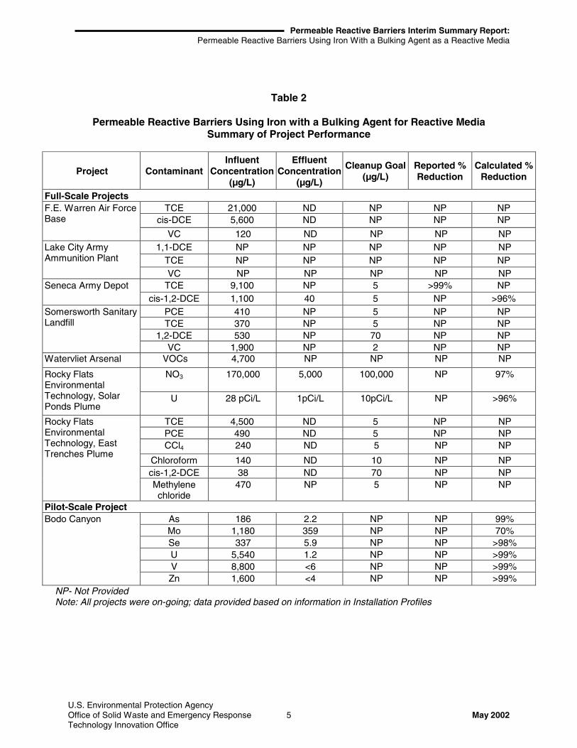
Table 2 summarizes the performance data provided for the eight projects. At the eight sites, thePRBs reduced individual contaminant concentrations that had ranged from 38 micrograms perliter (µg/L) to 170,000 to below site-specific cleanup goals ranging from non-detect to 70 µg/L(for chlorinated solvents). Because seven of the eight projects included in this report wereinstalled after 1999, information on the longevity of the eight PRBs included in the report was notavailable.

Permeable Reactive Barriers Interim Summary Report:Permeable Reactive Barriers Using Iron With a Bulking Agent as a Reactive Media
U.S. Environmental Protection AgencyOffice of Solid Waste and Emergency Response 4 May 2002Technology Innovation Office
One PRB that had not met its performance goal is the Seneca Army Depot site, where thecontaminants were TCE and cis-1,2-DCE. The cleanup goals at this site were based on theNew York State cleanup standards of 5 µg/L for both contaminants. The PRB reduced the TCEconcentration from 9,100 µg/L to non-detectable concentrations. The DCE in the effluent fromthe PRB ranged from 20 to 40 µg/L, which was higher than the cleanup goal of 5 µg/L. Thehigher concentration was attributed to greater than expected influent concentrations of TCE (thesource of the DCE via degradation pathway), and greater than expected groundwater velocity.The Seneca Project profile reported that TCE had been reduced by 98%.
Although performance goals were not provided for the Bodo Canyon PRB, data show thatindividual metal concentrations were reduced from as high 8,800 µg/L to less than 360 µg/L.The decrease in concentrations of individual contaminants was more than 99% for allcontaminants with the exception of molybdenum, which decreased by 70%. Performance datafor the Lake City Army Ammunition Plant are not yet available.
Permeable Reactive Barriers Interim Summary Report:Permeable Reactive Barriers Using Iron With a Bulking Agent as a Reactive Media
U.S. Environmental Protection AgencyOffice of Solid Waste and Emergency Response 5 May 2002Technology Innovation Office
Table 2
Permeable Reactive Barriers Using Iron with a Bulking Agent for Reactive MediaSummary of Project Performance
Project ContaminantInfluent
Concentration(µg/L)
EffluentConcentration
(µg/L)
Cleanup Goal(µg/L)
Reported %Reduction
Calculated %Reduction
Full-Scale ProjectsTCE 21,000 ND NP NP NP
cis-DCE 5,600 ND NP NP NPF.E. Warren Air ForceBase
VC 120 ND NP NP NP1,1-DCE NP NP NP NP NP
TCE NP NP NP NP NPLake City ArmyAmmunition Plant
VC NP NP NP NP NPTCE 9,100 NP 5 >99% NPSeneca Army Depot
cis-1,2-DCE 1,100 40 5 NP >96%PCE 410 NP 5 NP NPTCE 370 NP 5 NP NP
1,2-DCE 530 NP 70 NP NP
Somersworth SanitaryLandfill
VC 1,900 NP 2 NP NPWatervliet Arsenal VOCs 4,700 NP NP NP NP
NO3 170,000 5,000 100,000 NP 97%Rocky FlatsEnvironmentalTechnology, SolarPonds Plume
U 28 pCi/L 1pCi/L 10pCi/L NP >96%
TCE 4,500 ND 5 NP NPPCE 490 ND 5 NP NPCCl4 240 ND 5 NP NP
Chloroform 140 ND 10 NP NPcis-1,2-DCE 38 ND 70 NP NP
Rocky FlatsEnvironmentalTechnology, EastTrenches Plume
Methylenechloride
470 NP 5 NP NP
Pilot-Scale ProjectAs 186 2.2 NP NP 99%Mo 1,180 359 NP NP 70%Se 337 5.9 NP NP >98%U 5,540 1.2 NP NP >99%V 8,800 <6 NP NP >99%
Bodo Canyon
Zn 1,600 <4 NP NP >99%NP- Not ProvidedNote: All projects were on-going; data provided based on information in Installation Profiles
Permeable Reactive Barriers Interim Summary Report:Permeable Reactive Barriers Using Iron With a Bulking Agent as a Reactive Media
U.S. Environmental Protection AgencyOffice of Solid Waste and Emergency Response 6 May 2002Technology Innovation Office
Project Cost
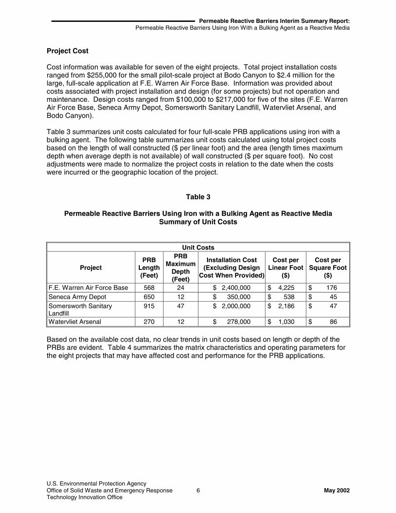
Cost information was available for seven of the eight projects. Total project installation costsranged from $255,000 for the small pilot-scale project at Bodo Canyon to $2.4 million for thelarge, full-scale application at F.E. Warren Air Force Base. Information was provided aboutcosts associated with project installation and design (for some projects) but not operation andmaintenance. Design costs ranged from $100,000 to $217,000 for five of the sites (F.E. WarrenAir Force Base, Seneca Army Depot, Somersworth Sanitary Landfill, Watervliet Arsenal, andBodo Canyon).
Table 3 summarizes unit costs calculated for four full-scale PRB applications using iron with abulking agent. The following table summarizes unit costs calculated using total project costsbased on the length of wall constructed ($ per linear foot) and the area (length times maximumdepth when average depth is not available) of wall constructed ($ per square foot). No costadjustments were made to normalize the project costs in relation to the date when the costswere incurred or the geographic location of the project.
Table 3
Permeable Reactive Barriers Using Iron with a Bulking Agent as Reactive MediaSummary of Unit Costs
Unit Costs
ProjectPRB
Length(Feet)
PRBMaximum
Depth(Feet)
Installation Cost(Excluding Design
Cost When Provided)
Cost perLinear Foot
($)
Cost perSquare Foot
($)
F.E. Warren Air Force Base 568 24 $ 2,400,000 $ 4,225 $ 176Seneca Army Depot 650 12 $ 350,000 $ 538 $ 45Somersworth SanitaryLandfill
915 47 $ 2,000,000 $ 2,186 $ 47
Watervliet Arsenal 270 12 $ 278,000 $ 1,030 $ 86
Based on the available cost data, no clear trends in unit costs based on length or depth of thePRBs are evident. Table 4 summarizes the matrix characteristics and operating parameters forthe eight projects that may have affected cost and performance for the PRB applications.

Permeable Reactive Barriers Interim Summary Report:Permeable Reactive Barriers Using Iron With a Bulking Agent as a Reactive Media
U.S. Environmental Protection AgencyOffice of Solid Waste and Emergency Response 7 May 2002Technology Innovation Office
Table 4
Permeable Reactive Barriers Using Iron with a Bulking Agent for Reactive MediaOperating Parameters
Operating ParametersParameter Range of Values
Soil Classification: Varied(provided for three projects)
Clay Content and/or Particle SizeDistribution:
Not provided
PH: Not providedPorosity: Not provided
Depth Below Ground Surface orThickness of Zone of Interest:
12 to 60 feet bgs
Total Organic Carbon: Not providedPresence of Nonaqueous-Phase
Liquids:Not provided
Groundwater Flow Rate: 0.3 to 2 gallons per minute (gpm)(provided for two projects)
Type of Reactive Media: Iron with bulking agents
Lessons Learned Related to PRBs Using Iron with Bulking Agents
The following is a summary of lessons learned from the eight projects included in this case studyaccording to the RTDF.
PRB Configuration
• At the Somersworth Sanitary Landfill, a continuous wall configuration was used ratherthan a funnel and gate configuration which may have altered the natural groundwaterflow in the area and caused mounding conditions. In addition, the configuration designand the bio-polymer construction method were effective and economical for a large Fe0
PRB. However, difficulties during construction identified a need to monitor the stability ofthe bio-polymer slurry during construction.
• For the Watervliet Arsenal PRB, groundwater modeling was used to design the PRB.The results showed that flow barriers (funnels) at the site would have created underflowand reduced wall efficiency. Also, modeling showed that walls not constructedperpendicular to groundwater flow could have created “piping,” leading to underflow ormounding, that would reduce wall efficiency.
PRB Installation Method
• For the Rocky Flats sites, it was reported that the length of open trench must beminimized to reduce slope failure, during construction equipment operations andstockpiling adjacent to open trenches must be minimized, maintenance operations mustbe considered in the design of the PRB, backfill specifications must be rigidly followed,and gravity flow would be most effective when the natural contours of a hillside can beused.
Permeable Reactive Barriers Interim Summary Report:Permeable Reactive Barriers Using Iron With a Bulking Agent as a Reactive Media
U.S. Environmental Protection AgencyOffice of Solid Waste and Emergency Response 8 May 2002Technology Innovation Office
Reactive Media Used
• Bulking agents have been combined with iron for use in PRBs to improve groundwaterflow conditions within the reactive zone, treat additional contaminants not addressed byiron alone, and reduce project costs.
• During installation of the Watervliet Arsenal PRB, it was not always possible to visuallydetermine whether the sand and iron mixture was mixed well because the iron and sandwere the same color. Consequently, samples were collected and the iron separated fromthe sand using a magnet.
Project Performance
• At the Seneca Army Depot, the PRB did not reduce the concentration of DCE to below itscleanup goal of 5 µg/L. The PRB would need to be thicker and comprised completely ofreactive material to remove DCE to meet the cleanup goal.
• The Bodo Canyon PRB reduced concentrations of a wide variety of constituents.However, the hydraulic head was limited by the elevation between the PRBs and theholding tank. In addition, gasses (H2 and CH4) that built up in the PRB required venting,and may have contributed to flow stoppage.
• For the Lake City Army Ammunition Plant, the project manager stated that severalquestions have been raised about whether the PRB is performing properly. Somecurrent theories are that because the viscosity and pH of the biodegradable slurry werenot maintained during installation, the trench collapsed during installation. The failuremay have led to a reduction in the permeability of the PRB, resulting in the mounding orgroundwater behind the barrier. It is unclear whether the PRB was effectively installed ata depth sufficient to be keyed into the underlying bedrock.
Project Cost
• Reduction of project cost was not reported as a factor for choosing iron with a bulkingagent for any of the PRBs included in this report. However, the Installation Profiles forthe Rocky Flats sites reported that the estimated cost for a PRB employing iron with abulking agent as a reactive media was approximately one-quarter of the estimated costfor a baseline pump and treat system.
• Unit costs for the four continuous wall PRB applications with cost information at whichchlorinated VOCs were treated ranged from $538 to $4,225 per linear foot and from $45to $176 per square foot. It is likely that matrix characteristics and operating parameterssuch as soil classification; clay content and particle size distribution; pH; porosity; depthbgs or thickness of zone of interest; total organic carbon; presence of NAPLs;groundwater flow rate; and type of reactive media, also may be direct or indirect factorsin project cost. However, because of the dissimilarity between sites profiled in the casestudy, more significant conclusions regarding PRB cost could not be made.

Permeable Reactive Barriers Interim Summary Report:Permeable Reactive Barriers Using Iron With a Bulking Agent as a Reactive Media
U.S. Environmental Protection AgencyOffice of Solid Waste and Emergency Response 9 May 2002Technology Innovation Office
References
EPA. 2002a. Field Applications of In Situ Remediation Technologies: Permeable ReactiveBarriers. U.S. Environmental Protection Agency, Office of Solid Waste and EmergencyResponse, Technology Innovation Office. January.
EPA. 2002b. Remediation and Characterization Innovative Technologies.<www.EPAReachIT.org>. U.S. Environmental Protection Agency, Office of Solid Waste andEmergency Response, Technology Innovation Office. April.
ITRC. 1999. Regulatory Guidance for Permeable Reactive Barriers Designed to RemediateInorganic and Radionuclide Contamination. Interstate Technology Regulatory CommissionSeptember.
RTDF. 2002. Permeable Reactive Barrier Installation Profiles.<www.rtdf.org/public/permbarr/prbsumms/> Remediation Technologies Development Forum.April.
U.S. Air Force Research Laboratory. 2000. Design Guidance for Application of PermeableReactive Barriers for Groundwater Remediation. March.
Analysis Preparation
This case study was prepared for the U.S. Environmental Protection Agency’s Office of SolidWaste and Emergency Response, Technology Innovation Office. Assistance was provided byTetra Tech EM Inc., under Contract No. 68-W-02-034.

Permeable Reactive Barriers Summary Report:Permeable Reactive Barriers Interim Using Iron With a Bulking Agent as a Reactive Media
U.S. Environmental Protection AgencyOffice of Solid Waste and Emergency Response 10Technology Innovation Office May 2002
Table 1
Permeable Reactive Barriers Using Iron With a Bulking Agent as a Reactive MediaProject Summary Information
Site Name and LocationYear
InstalledConstruction
Method
Wall Dimensions(Length and
Maximum Depth)Reactive Media Contaminant
Install Cost(Design Cost)
Full Scale Walls
F.E. Warren Air ForceBase, Cheyenne, WY
1999 Supportedexcavation
568 ft long, 24 ft deep Iron and sand TCE;, cis-DCE; VC $2,400,000($217,000)
Lake City Army AmmunitionPlant, Independence MO
2000 Supportedexcavation
400 ft long, 60 ft bgs Iron and sand TCE; 1,1-DCE; VC Not provided
Seneca Army Depot,Romulus NY
1999 Continuoustrenching
650 ft long, 12 ft bgs Iron and sand TCE; cis 1,2-DCE $350,000($100,000)
Somersworth SanitaryLandfill, Somersworth, NH
2000 Supportedexcavation
915 ft long, 47 ft bgs (8sections, 100 ft each)
Iron and sand PCE; TCE; cis 1,2-DCE; VC $2,000,000($200,000)
Watervliet Arsenal,Watervliet, NY
1999 Supportedexcavation
270 ft long, 12 ft bgs (2sections, 180 ft and 90 ft)
Iron and sand Chlorinated VOCs – specificcontaminants not specified
$278,000($113,000)
Full Scale Reaction Vessels
Rocky Flats EnvironmentalTechnology Solar PondsPlume, Golden, CO
1999 SupportedExcavation
Trench-1,100 ft by 30 ftbgs (2 vessels)
Iron and woodchips
Nitrate; U $1,300,000
Rocky Flats EnvironmentalTechnology East TrenchesSite, Golden CO
1999 Supportedexcavation
Trench-1,200 ft by 26 ftbgs (2 vessels)
Iron and peagravel
TCE; PCE; Carbontetrachloride; Chloroform; cis1,2-DCE; Methylene chloride
$1,300,000
Pilot Scale Reaction Vessel
Bodo Canyon, Durango, CO 1995 Not provided Not provided Iron, copperwool, and steelwool
As; Mo; Se; U; V; Zn $255,000($125,000)

Permeable Reactive Barriers Summary Report:Permeable Reactive Barriers Using Iron With a Bulking Agent as a Reactive Media
U.S. Environmental Protection AgencyOffice of Solid Waste and Emergency Response 11 May 2002Technology Innovation Office
Figure 1
Schematic Diagram of Continuous Reactive Wall at the Somersworth SanitaryLandfill
Source: RTDF

Permeable Reactive Barriers Summary Report:Permeable Reactive Barriers Using Iron With a Bulking Agent as a Reactive Media
U.S. Environmental Protection AgencyOffice of Solid Waste and Emergency Response 12 May 2002Technology Innovation Office
Permeable Reactive Barrier Project Profile:F.E. Warren Air Force Base, Cheyenne, WY
Installation Year: 1999Contaminants: cis-Dichloroethene, Trichloroethene, Vinyl Chloride
Reactive Media: Iron and sandCost: $2,617,000
Construction: Trench BoxPoint of Contact: Ernesto J. Perez
HQ AFCEE/ERD-FEWF.E. Warren AFB300 Vesle Drive, Suite 600Cheyenne, WY 82005-2778Telephone: 307-773-4356Facsimile: 307-773-4153Email: [email protected]
A full-scale permeable reactive barrier (PRB) was installed as an Interim Remedial Action (IRA)at F.E. Warren Air Force Base Spill Site 7 in Cheyenne, WY in 1999. The constructioncontractor chose a trench box system because of subsurface conditions and requirements fortracking iron usage. Trichloroethylene (TCE), cis-dichloroethylene (cis-DCE), and vinyl chloride(VC) are the contaminants of concern at the site. Initial concentrations encountered at the sitewere 21,000 µg/L for TCE, 5,600 µg/L for cis-DCE, and 120 µg/L for VC.
Spill Site 7 is an area where waste solvents associated with liquid oxygen production weredischarged to a surface drainage ditch and infiltrated to groundwater at depths of 8-20 ft. Theheterogeneous aquifer and geotechnical properties complicated the placement and compositionof the PRB. The existing infrastructure on the site and the rare and endangered species areadown gradient of the site added further limitations to the placement of the PRB. There is a 4-ftground-water elevation fluctuation and no well-defined confining layer. Hydraulic conductivityvaries from 0.01-4 ft/day.
The PRB consists of 3 segments, each 4 ft wide and ranging in length from 155-251 ft, a total of568 ft long. Each segment contains a different mix and thickness of reactive media dependingon the ground-water velocity and level of contaminants. One segment consists of pure ironfilings, another a 25%/75% mix of iron and sand, and the third a 37.5%/62.5% mix of iron andsand. The vertical depth of the PRB is 15 ft, while the depth below ground surface ranges from6-24 ft. Installation costs including materials, construction, oversight, and the technologylicensing fee, totaled approximately $2.4 million. Design costs were approximately $217,000.
Samples taken down gradient of the PRB indicate that concentrations of TCE and itsdegradation products (cis-DCE and VC), were reduced to non-detectable levels. Sampling wasconducted quarterly for the first year and semi-annually thereafter.
Lessons Learned
Successful PRB designs often require extensive site characterization in the pre-design phase.Successful installations require effective site layout, construction sequence, and heavyequipment selection. Construction methods must be flexible enough to be modified toaccommodate unforseen conditions. A complete understanding of the characteristics andbehavior of backfill material is important.

Permeable Reactive Barriers Summary Report:Permeable Reactive Barriers Using Iron With a Bulking Agent as a Reactive Media
U.S. Environmental Protection AgencyOffice of Solid Waste and Emergency Response 13 May 2002Technology Innovation Office
Note: This is the complete installation profile provided by the Remediation TechnologyDevelopment Forum (www. rtdf.org) for this project. Included in this project profile arephotographs of the installation of the PRB.

Permeable Reactive Barriers Summary Report:Permeable Reactive Barriers Using Iron With a Bulking Agent as a Reactive Media
U.S. Environmental Protection AgencyOffice of Solid Waste and Emergency Response 14 May 2002Technology Innovation Office
Permeable Reactive Barrier Project Profile:Lake City Army Ammunition Plant, Independence, MO
Installation Year: 2000Contaminants: 1,1-Dichloroethene, Trichloroethene, Vinyl Chloride
Reactive Media: Iron and sandCost: Information not provided
Construction: Continuous wallPoint of Contact: Scott Marquess
Remedial Project ManagerU.S. EPA, Region 7901 North Fifth StreetKansas City, KS 66101Telephone: (913) 551-7131Facsimile: (913) 551-7063Email: [email protected]
In 2000, a full-scale permeable reactive barrier (PRB) continuous wall was installed at the LakeCity Army Ammunition Plant (LCAAP) Superfund Site in Independence, Missouri to treatgroundwater contaminated with 1,1-dichloroethene (DCE), trichloroethene (TCE), and vinylchloride (VC). This site is a Superfund remedial site that is a cooperative effort by the U.S.Department of Defense and U.S. EPA Region 7.
The area at the LCAAP that is the focus of the PRB is referred to as Area 18, which is located inthe northern central portion of the site. This area was used as a disposal area for industrialwastewater, oil and grease, solvents, plant trash, and demolition waste and contained solventdisposal pits, which are the primary sources of contamination in Area 18. DCE, TCE, and VCare present in the groundwater and lead and other metals are present in the surface soil.
The PRB system at the site was installed using a trench excavator and biodegradable slurry.The wall is approximately 400 feet in length. It was installed to a maximum depth of 60 feetbelow ground surface (bgs) and was intended to be keyed into the underlying shale bedrock. Amixture of 26% iron and 74% sand was used in the PRB as a reactive media.
There were several issues identified by the Remedial Project Manager (RPM) during the PRBinstallation phase. The trench failed during construction apparently because the viscosity andpH of the biopolymer slurry was not maintained. Once the wall was installed, artesian conditionswere observed on the upgradient side of the wall. Groundwater was mounding behind the wall,apparently due to insufficient flow through the wall caused by the trench failure duringconstruction. Also, it was unclear as to whether the wall had actually been keyed into the shalebedrock.
No cost or performance results are available at this time and the project is awaiting more fundingbefore further action is taken.
Note: This project was identified in the EPA REACHIT database <www.EPAReachIt.org>.The EPA RPM provided additional information on the current status of the project.

Permeable Reactive Barriers Summary Report:Permeable Reactive Barriers Using Iron With a Bulking Agent as a Reactive Media
U.S. Environmental Protection AgencyOffice of Solid Waste and Emergency Response 15 May 2002Technology Innovation Office
Permeable Reactive Barrier Project Profile:Seneca Army Depot Activity, Romulus, New York
Installation Year: 1999Contaminants: Trichloroethene and cis-1,2-Dichloroethene
Reactive Media: Iron and sandCost: $450,000
Construction: Continuous wallPoint of Contact: Michael Duchesneau
Parsons Engineering Science, Inc.30 Dan RoadCanton, MA 02021-2809Telephone: (781) 401-2492Facsimile: (781) 401-2492Email: [email protected]
A full-scale demonstration permeable reactive barrier (PRB) system was installed at SenecaArmy Depot Activity in Romulus, New York in 1999. Continuous wall trenches were chosenbased on the system’s lower cost, ease of installation, expectation of less disruption ingroundwater flow, and ability to treat the upper surface of the bedrock aquifer. Trichloroethene(TCE) and cis-1,2-dichloroethene (DCE) are the contaminants of concern at the site. Followinga removal action using low temperature thermal desorption (LTTD) in 1996, the concentrationsdropped from 51,000 to 9,100 µg/L for TCE and from 130,000 to 1,100 µg/L for cis-DCE.
The site is an ash landfill area for a former trash incinerator used for the disposal of chlorinatedsolvents. A TCE/DCE groundwater plume (1,200 ft long by 600 ft wide) emanated from the ashlandfill source area. The geological matrix is comprised of 6 by 8 ft of glacial till with fracturedshale to 20 ft. The depth of the water varies over the year from ground surface to 6 to 8 ft belowground surface (bgs). The average hydraulic conductivity of the glacial till is 1.8 x 10⁻⁴ in/sec andthat of the fractured shale is 1.4 x 10⁻⁵ in/sec. The shale conductivity decreased with increasingdepth. There is poor connection between the overburden and the bedrock.
The PRB is 650 ft long, 14 in wide, and 7 to 12 ft deep with a cover of approximately 1 ft ofnatural soil. It is installed from the ground surface into the top 1 to 2 ft of the weathered shalebedrock. The 5,525 ft3 of reactive material used is a 50/50 mixture of zero valent iron (Fe0) andsand. The total installation cost including construction and materials was $350,000. Designcosts, including a 3-D groundwater model, were $100,000.
The cleanup goal was based on the New York State standard of 5 µg/L. Samples taken after 4quarters of monitoring revealed 100% removal of TCE. Removal of cis-DCE was less thanexpected. Concentrations downgradient and within the wall were measured at 20-40 µg/L.Removal of DCE will require additional reactive iron. Future walls are pending if DCE removalcan be achieved. Sampling continues intermittently as funding allows.
Lessons Learned
Monitoring results indicate that walls will need to be thicker and comprised of 100% reactivematerial. Incomplete treatment of cis-DCE was attributed to greater than expected PRB influentconcentrations of TCE (500 as opposed to 100 µg/L) and greater than expected variability ofgroundwater velocities. These variations necessitate the installation of additional monitoring

Permeable Reactive Barriers Summary Report:Permeable Reactive Barriers Using Iron With a Bulking Agent as a Reactive Media
U.S. Environmental Protection AgencyOffice of Solid Waste and Emergency Response 16 May 2002Technology Innovation Office
wells to determine concentrations and velocities. Column study tests of the reactive iron mayalso be needed to determine if the reactivity of the iron may have contributed to the DCEbreakthrough.
Note: This is the complete installation profile provided by the Remediation TechnologyDevelopment Forum <www.rtdf.org> for this project. Included in this project profile arephotographs of the installation of the PRB at this site.

Permeable Reactive Barriers Summary Report:Permeable Reactive Barriers Using Iron With a Bulking Agent as a Reactive Media
U.S. Environmental Protection AgencyOffice of Solid Waste and Emergency Response 17 May 2002Technology Innovation Office
Permeable Reactive Barrier Project Profile:Somersworth Sanitary Landfill Superfund Site, Somersworth, New Hampshire
Installation Year: 2000Contaminants: Tetrachloroethene; Trichloroethene; 1,2-Dichloroethene;
and Vinyl ChlorideReactive Media: Iron and sand
Cost: $2,200,000Construction: Continuous wall
Point of Contact: Tom KrugGeoSyntec Consultants160 Research Lane, Suite 206Guelph, Ontario, CanadaTelephone: (519) 822-2230Facsimile: Not providedEmail: [email protected]
A full-scale permeable reactive barrier (PRB) system was installed in 2000 at the SomersworthSanitary Landfill Superfund Site in Somersworth, New Hampshire. The site is a 26-acre landfillthat was constructed in the early 1930s on the site of a former sand and gravel quarry. Thelandfill was used to dispose of household trash, business refuse, and industrial wastes. Wastewas burned at the landfill until 1958. From 1958 to 1981, the waste material was placed inexcavated areas, compacted, and covered with soil. In 1981, use of the landfill stopped whenthe City of Somersworth began disposing of its municipal waste at a regional incinerator. Also in1981, the City implemented a closure plan for the landfill that involved the covering of a portionof the landfill with clean fill. Volatile organic compounds (VOCs), including tetrachloroethene(PCE) trichloroethene (TCE), 1,2-dichloroethene (DCE), and vinyl chloride (VC) were found to bepresent in the groundwater. Initial concentrations encountered were up to 410 µg/L for PCE, upto 370 µg/L for TCE, up to 530 µg/L for 1,2-DCE, and up to 1,900 µg/L for VC.
The site is characterized by sands and gravels having a hydraulic conductivity in the range of0.02 cm/second. The hydraulic gradient varies from 0.01 to 0.004 ft/ft near the edge of thewaste. The top of the water table ranges from less than 2 to 20 ft below ground surface. Asmuch as 10% of the waste is located below the water table. The aquifer is 30-40 ft thick.
The PRB is a continuous wall 915 ft long and extending to a depth of 26 to 47 ft below theground surface. The PRB was designed with 8 sections, each approximately 100 ft long, withdiffering amounts of zero-valent iron (Fe0) corresponding to the Fe0 required to treat the specificconcentration of VOCs entering each section of the PRB. The vertical interval of the PRB(interval containing Fe0) ranges from 20 to 40 ft. A continuous wall was used for the PRB asopposed to a funnel-and-gate system to reduce the impacts on the existing groundwater flowconditions at the site and to reduce the potential for mounding of groundwater on the upgradientside of the PRB. The cleanup goals for VOC contaminants are: 5 µg/L for PCE; 5 µg/L for TCE;70 µg/L for cis-1,2-DCE; and 2 µg/L for VC.
The PRB was installed using an open trench supported by a biodegradable bio-polymer slurry.This installation method was used because of its low cost and suitability for site conditions.
The construction method dictated that the PRB have a minimum thickness of 30 in,corresponding to the width of the excavator bucket. Inert, coarse washed sand was mixed withthe Fe0 before being placed in the trench. The different sections of the PRB contained Fe0-sand

Permeable Reactive Barriers Summary Report:Permeable Reactive Barriers Using Iron With a Bulking Agent as a Reactive Media
U.S. Environmental Protection AgencyOffice of Solid Waste and Emergency Response 18 May 2002Technology Innovation Office
mixtures with between 40% and 100% Fe0 by weight. Total design cost for the systemamounted to $200,000; construction/installation cost, including the cost of Fe0, totaled$2,000,000.
Some difficulties were encountered during installation. The PRB was divided into 23 separatepanels, each typically 30 to 50 ft long. The contractor initially installed alternating panels(primary panels) along the length of the PRB, then installed secondary panels between theprimary panels. Typically, primary panels were excavated in one day. During the installation ofthe primary panels, the bio-polymer remained stable (i.e., maintained sufficient viscosity tosupport the trench) overnight or in some cases for several days. During the installation of thefirst two secondary panels, the contractor had difficulties maintaining the stability of thebio-polymer and some sand and silt settled out into the bottom of the trench before the Fe0 wasplaced in the trench. Following these difficulties, the contractor excavated and backfilledsecondary panels in a single day and difficulties with subsequent panels were averted. The areaaffected by the silt and sand represents approximately 1% of the PRB. The difficulties duringconstruction have not had any measurable effect on the performance of the PRB. Sampling isbeing conducted three times per year to monitor PRB performance.
Groundwater monitoring conducted during the first year following installation shows that the PRBis operating as designed. Ongoing groundwater monitoring required by the Consent Decree forthe Site is being conducted three times per year.
Lessons Learned
The approach to the design and the bio-polymer construction method were demonstrated to beeffective and economical for a large Fe0 PRB. Difficulties during construction highlighted theneed to monitor the stability of the bio-polymer slurry during construction.
Note: This is the complete installation profile provided by the Remediation TechnologyDevelopment Forum <www.rtdf.org> for this project. Included in this project profile arephotographs, and a schematic diagram of the PRB at this site.

Permeable Reactive Barriers Summary Report:Permeable Reactive Barriers Using Iron With a Bulking Agent as a Reactive Media
U.S. Environmental Protection AgencyOffice of Solid Waste and Emergency Response 19 May 2002Technology Innovation Office
Permeable Reactive Barrier Project ProfileWatervliet Arsenal, Watervliet, New York
Installation Year: 1999Contaminants: Volatile Organic Compounds
Reactive Media: Iron and concrete sandCost: $391,000
Construction: Continuous wallPoint of Contact: Grant A. Anderson
U.S. Army Corps of Engineers10 South Howard St.Baltimore, MD 21201Telephone: (410) 962-6645Facsimile: (410) 962-7731Email: [email protected]
Two continuous walls have been installed for full-scale cleanup of groundwater at the WatervlietArsenal, the oldest cannon manufacturing facility in the United States. Years of land disposal ofwastes from the manufacturing of cannons and the operation of a burn pit contaminatedgroundwater with up to 4,700 µg/L of volatile organic compounds (VOCs).
The site is underlain by a layer of fill extending 10 to 12 ft below ground surface (bgs) andconsisting of mixed sands, clay, rubble, and wood. The hydraulic conductivity of this layer isapproximately 8.9 ft/day, and the hydraulic gradient is 0.16 ft/ft. Underlying the fill is a tight(hydraulic conductivity of 0.45 ft/day) layer of lacustrine silt, clay, and peat atop weatheredbedrock. The water table is situated within the fill at 2 to 5 ft bgs. The seasonal fluctuation ofthe water table is 2 to 3 ft.
Two 3-ft-wide and 8- to 12-ft-deep continuous walls were constructed with the goal of reducinglevels of chlorinated VOCs to non-detect immediately downgradient of the walls. The southernwall, constructed perpendicular to groundwater flow, is 180 ft long; the northern wall, locatedfurther downgradient, is 90 ft long. The walls were constructed using a conventionaltrack-mounted excavator, and the trenches held open with shoring plates with “speed shores”. Amixture of granular iron and concrete sand were placed manually from transit trucks usingchutes. The total amount of reactive materials used was 165 tons of iron and 163 tons of sand.
During installation, it was not always possible to visually determine whether or not the sand/ironmixture was well mixed because the iron and sand were the same color. As a result, sampleshad to be collected and the iron separated from the sand using a magnet. Each component wasweighed and the results were compared to the concrete plant’s weight slips to ensure propermixing.
The installation cost of the walls, which includes construction and materials only, was $278,000;the design cost was $113,000. These costs are estimated to be about one-third the cost ofdesigning and building a pump and treat system, and the O&M costs over a 30-year period areexpected to be approximately $3 million lower.
One advantage of the constructing the treatment walls rather than a pump-and-treatment systemis that the remediation area can be used largely without restriction since there are no plumbingsystems or treatment plants to interfere with traffic or storage at the site. However, the presenceof the walls may limit other remedial measures and construction. For example, a pump-and-treat

Permeable Reactive Barriers Summary Report:Permeable Reactive Barriers Using Iron With a Bulking Agent as a Reactive Media
U.S. Environmental Protection AgencyOffice of Solid Waste and Emergency Response 20 May 2002Technology Innovation Office
system could not be installed in the deeper bedrock aquifer to address possible contaminationnear the wall. Any dewatering of the surficial aquifer would defeat the operation of the walls.
Monitoring of groundwater quality at Watervliet Arsenal shows that the walls are meeting projectgoals. Long-term monitoring will continue twice per year.
Lessons Learned
Thus far in this project, constructing the continuous walls has shown that groundwater modelingcan be a powerful tool for design. Studies showed that flow barriers (funnels) would havecreated underflow and reduced wall efficiency. Also, modeling showed that walls notconstructed perpendicular to groundwater flow could have created “piping”, which causesunderflow or mounding. This would change the hydrodynamics of the system and could affectthe residence time of groundwater in the walls. It was difficult to estimate the amount of waterthat would enter a trench during installation. The estimate, made by excavating a test pit,resulted in the selection of a holding tank that was many orders of magnitude too large.
Note: This is the complete installation profile provided by the Remediation TechnologyDevelopment Forum <www.rtdf.org> for this project.

Permeable Reactive Barriers Summary Report:Permeable Reactive Barriers Using Iron With a Bulking Agent as a Reactive Media
U.S. Environmental Protection AgencyOffice of Solid Waste and Emergency Response 21 May 2002Technology Innovation Office
Permeable Reactive Barrier Project Profile:Rocky Flats Environmental Technology Site (Solar Ponds Plume),Golden, Colorado
Installation Year: 1999Contaminants: Nitrate and Uranium
Reactive Media: Iron and wood chipsCost: $1,300,000
Construction: Reaction vesselsPoint of Contact: Annette Primrose
Kaiser-Hill Co, LLCRocky Flats Environmental Technology Site10808 Highway 93, Unit B, Building 116Golden, CO 80403-8200Telephone: (303) 966-4385Facsimile: (303) 966-5180Email: [email protected]
Full-scale permeable reactive barrier (PRB) systems have been installed to treat contaminatedground water at three sites at the U.S. Department of Energy's Rocky Flats EnvironmentalTechnology Site (RFETS) in Golden, Colorado. These projects were a cooperative effortbetween RFETS and the Department of Energy (DOE) Subsurface Contaminant Focus Area,with support from U.S. EPA's National Risk Management Research Laboratory.
Another of these PRB systems was installed in 1999 to treat contaminated groundwater at theSolar Ponds Plume where, as a result of past waste storage practices, nitrate (NO3) and uranium(U) are present in excess of the Action Level Framework Tier I level groundwater concentrationsdefined in the RFCA. The Solar Ponds were drained and the sludges removed by 1995, butcontaminated groundwater migrated away from the source area to a nearby creek. Contaminantconcentrations at the Solar Ponds Plume are: NO3 at 140 to 170 mg/L and U at 20 to 28 pCi/L.The treatment goal is to meet surface water standards of 100 mg/L of nitrate and 10 pCi/L ofuranium in the adjacent creek. These goals are currently being achieved.
The groundwater collection system at the Solar Ponds Plume extends approximately 1,100 ft.To install the collection system, an excavation was dug at a variable depth of approximately 20to 30 ft bgs and approximately 10 ft into claystone. The barrier consists of the same HDPEpanels as the barrier at the East Trenches Plume; it was installed and operates in the same way.
The below grade, concrete treatment cell is divided into two sections. Treatment mediaoccupies the lower 10 ft of each section. The first cell is about 32 ft long and 17 ft wide and isfilled with a mixture of sawdust and leaf mold with 10% zero-valent iron (Fe0) by weight to inducedenitrification and to remove the uranium by chemical reduction. The media was selected on thebasis of bench scale tests conducted at the University of Waterloo. The second cell is about 11ft long and 17 ft wide and is filled with Fe0 to act as a final polisher. The two treatment cells canbe run in series or in parallel.
Water exiting the treatment cell typically contains less than 5 mg/L NO3 and less than 1 pCi/L U.While the PRB system does not collect and treat all the groundwater in this plume, the surfacewater standards are consistently met in the nearby creek.

Permeable Reactive Barriers Summary Report:Permeable Reactive Barriers Using Iron With a Bulking Agent as a Reactive Media
U.S. Environmental Protection AgencyOffice of Solid Waste and Emergency Response 22 May 2002Technology Innovation Office
Lessons Learned
Lessons learned to date from these installations include the following: (1) during construction,the length of trench open must be minimized to reduce slope failure, (2) equipment operationsand stockpiling adjacent to open trenches must be minimized, (3) maintenance must beconsidered in a PRB's design, (4) backfill specifications must be rigidly followed, (5) gravity flowis most effective when the natural contours of a hillside can be utilized; and (6) cost estimatedfor this system are about one-fourth of the estimated baseline “pump-and-treat” costs.
Note: This is the complete installation profile provided by the Remediation TechnologyDevelopment Forum <www.rtdf.org> for this project. Included in this project profile is alink to a website that contains additional information about this site: <www.envnet.org>

Permeable Reactive Barriers Summary Report:Permeable Reactive Barriers Using Iron With a Bulking Agent as a Reactive Media
U.S. Environmental Protection AgencyOffice of Solid Waste and Emergency Response 23 May 2002Technology Innovation Office
Permeable Reactive Barrier Project Profile:Rocky Flats Environmental Technology Site (East Trenches Site),Golden, Colorado
Installation Year: 1999Contaminants: Trichloroethene, Tetrechloroethene, Carbon Tetrachloride, Chloroform,
cis-1,2-Dichlororethene, Methylene ChlorideReactive Media: Iron and pea gravel
Cost: $1,300,000Construction: Reaction vessels
Point of Contact: Annette PrimroseKaiser-Hill Co, LLCRocky Flats Environmental Technology Site10808 Highway 93, Unit B, Building 116Golden, CO 80403-8200Telephone: (303) 966-4385Facsimile: (303) 966-5180Email: [email protected]
Full-scale permeable reactive barrier (PRB) systems have been installed to treat contaminatedground water at three sites at the U.S. Department of Energy's Rocky Flats EnvironmentalTechnology Site (RFETS) in Golden, Colorado. These projects were a cooperative effortbetween RFETS and the Department of Energy (DOE) Subsurface Contaminant Focus Area,with support from U.S. EPA's National Risk Management Research Laboratory.
The same type of PRB system was installed in 1999 to treat contaminated ground water at theEast Trenches Plume. As a result of past waste storage practices, VOCs are present in excessof the Action Level Framework Tier I level ground-water concentrations defined in the RockyFlats Cleanup Agreement. Sources were removed in 1996, but the contaminated groundwatermigrated away from source areas towards a nearby creek. Contaminant concentrations at theEast Trenches plume are primarily: trichloroethene (TCE), 2,700 to 4,500 µg/L;tetrachloroethene (PCE), 250 to 490 µg/L; carbon tetrachloride (CCl4), 130 to 240 µg/L;chloroform, 82 to 140 µg/L; cis-1,2-dichloroethene (DCE), 23 to 38 µg/L; and methylene chloride,6 to 470 µg/L. The treatment goal at the site is to remove contaminants of concern (COCs) tobelow Action Levels specified in the Rocky Flats Cleanup Agreement. This involves removal ofthe volatile organic compounds (VOCs) as follows—TCE to 5 µg/L; PCE to 5 µg/L; CCl4 to 5µg/L; chloroform to 100 µg/L; cis-1,2-DCE to 70 µg/L; and methylene chloride 5 µg/L.
The groundwater collection system for the East Trenches Plume PRB system extendsapproximately 1,200 ft. To install the collection system, an excavation was dug at a variabledepth of approximately 16 to 26 ft below ground surface, at least 6 in and an average of 3 ft intoclaystone. The barrier was installed on the downgradient side of the excavation and consists of80-mil high-density polyethylene (HDPE) panels fitted with an interlocking strip on each side.The trench was backfilled with sand and includes a perforated HDPE groundwater collection linethat was placed on the sand, and piped to a central collection sump. The collected groundwaterthen flows by gravity from the collection sump through a 2-in, non-perforated HDPE line to thetwo treatment cells.
Each treatment cell is approximately 12 ft in diameter and 13 ft tall. Groundwater enters thecells at the top and percolates through the 6.5 ft of iron. There is 1 ft of granular material on the

Permeable Reactive Barriers Summary Report:Permeable Reactive Barriers Using Iron With a Bulking Agent as a Reactive Media
U.S. Environmental Protection AgencyOffice of Solid Waste and Emergency Response 24 May 2002Technology Innovation Office
bottom of each treatment cell to disperse the groundwater. The upper foot of each cell is a50/50 mixture of iron and pea gravel to simplify mechanical break-up of the expected crustformation.
Results have shown that, with the exception of methylene chloride, concentrations of VOCs areroutinely non-detectable in the effluent samples.
Lessons Learned
Lessons learned to date from these installations include the following: (1) during construction,the length of trench open must be minimized to reduce slope failure, (2) equipment operationsand stockpiling adjacent to open trenches must be minimized, (3) maintenance must beconsidered in a PRB's design, (4) backfill specifications must be rigidly followed, (5) gravity flowis most effective when the natural contours of a hillside can be utilized; and (6) cost estimatedfor this system are about one-fourth of the estimated baseline “pump-and-treat” costs.
Note: This is the complete installation profile provided by the Remediation TechnologyDevelopment Forum <www.rtdf.org> for this project. Included in this project profile is alink to a website that contains additional information about this site: <www.envnet.org>

Permeable Reactive Barriers Summary Report:Permeable Reactive Barriers Using Iron With a Bulking Agent as a Reactive Media
U.S. Environmental Protection AgencyOffice of Solid Waste and Emergency Response 25 May 2002Technology Innovation Office
Permeable Reactive Barrier Project Profile:Bodo Canyon, Durango, Colorado
Installation Year: 1995Contaminants: Arsenic, Molybdenum, Selenium, Uranium, Vanadium, Zinc
Reactive Media: Iron, copper wool, steel woolCost: $380,000
Construction: Collection drain piped to underground treatment systemPoint of Contact: Don Metzler
U.S. Department of Energy2597 B 3/4 RoadGrand Junction, CO 81503Telephone: (970) 248-7612Facsimile: (970) 248-6040Email: [email protected]
A pilot-scale demonstration of permeable reactive barriers (PRBs) was installed at Bodo Canyonin Durango, Colorado in 1995. The demonstration was conducted to help treat contaminatedwater seeping from a tailings disposal cell and test the efficiency of PRBs for remediation ofuranium and metals.
Operation of PRB E began in the Spring 2000. Installation costs for the four PRBs, includingconstruction and materials, was approximately $255,000. Design costs were about $125,000.Contaminants of concern at the site are arsenic (As), molybdenum (Mo), selenium (Se), uranium(U), vanadium (V), and zinc (Zn). Concentration of contaminants in the untreated water are186 µg/L for As, 1180 µg/L for Mo, 337 µg/L for Se, 5540 µg/L for U, 8800 µg/L for V, and1600 µg/L for Zn.
A total of 2.5 million yd3 of uranium mill tailings were relocated to the Bodo Canyon disposal cellin the fall of 1990. Contaminated seeps developed along the downgradient slope of the disposalcell shortly after construction. The seep water was collected by a collection drain and piped to aretention pond, where it was regularly treated and discharged to a nearby wash.
In order to be able to compare different designs, four PRBs were installed near the retentionpond. Contaminated groundwater in the collection drain (328 ft long, 4 ft wide, and 3 ft high) isdiverted to a holding tank. Water from the holding tank flows to a manifold that distributes it tothe PRB. Because of the limited water flow in the area, only one PRB operates at a time and thesystem is shut down during the winter. Flow rates vary from 0.3 to 2 gallons per minute (gpm).
Zero valent iron (Fe0) in a variety of forms was used in each of the PRBs. Two of the PRBswere constructed similarly to septic leach fields, one containing steel wool (PRB A) and thesecond containing steel wool and copper wool (PRB B). Each of these systems is 20 ft wide, 3 ftlong, and 7 ft high. The reactive media is about 12 in thick. The remaining two PRBs wereconstructed in steel tanks with baffles that forced the water to flow up and down through thePRB. One tank contained Fe0 foam plates (PRB C) and the other contained steel wool (PRB D).The foam plates were manufactured by binding fine-grained Fe0 with aluminosilicate. Each ofthese tanks is 6 ft long, 3 ft wide, and 4.2 ft deep. Approximately 70 ft3 of reactive media wasused in PRBs C and D. The baffled tanks were used because the reactive media could beeasily changed.

Permeable Reactive Barriers Summary Report:Permeable Reactive Barriers Using Iron With a Bulking Agent as a Reactive Media
U.S. Environmental Protection AgencyOffice of Solid Waste and Emergency Response 26 May 2002Technology Innovation Office
Because of the limited flow out of the disposal cell and the fact that this was developed as a pilotdemonstration project, three of the four PRBs were shut down. PRB A never ran at all; B ran forapproximately one year, and D for two months. In July 1999, PRB C was excavated and 72samples of the solid foam plates were collected. After complete removal of the plates, PRB Cwas refilled with granular Fe0 (mesh size -8+20) and renamed PRB E. The change to granularFe0 was made in order to test the effectiveness of a more commonly used reactive media.
The baffled tank with Fe0 foam plates (PRB C) operated the longest. Effluent concentrations inMay 1999 were 2.2 µg/L for As, 359 µg/L for Mo, 5.9 µg/L for Se, 1.2 µg/L for U, <6 µg/L for V,and <4 µg/L for Zn. After 3 years, flow ceased in PRB C, probably due to mineral plugging.Water samples taken at PRB D indicated significant reductions in U concentrations from 7,430µg/L to 738 µg/L with a flow rate of 0.66 gpm. Early in the project, samples were taken almostmonthly. They are currently being taken semi-annually.
Lessons Learned
The PRB reduced concentrations of a wide variety of constituents. The hydraulic head is limitedby the elevation between the PRBs and the holding tank. Additional head would be useful tokeep the flow from stopping due to small decreases in hydraulic conductivity in the PRB.Gasses (H2 and CH4) that built up in the PRB required venting before accessing. The gassesmay also have contributed to flow stoppage. The collection drain/PRB system is useful becauseit can easily be replaced and the flux of water is well known.
Note: This is the complete installation profile provided by the Remediation TechnologyDevelopment Forum <www.rtdf.org> for this project. Included in this project profile is alink to a website with additional information on this site: <www.gjo.doe.gov>.