design a 161 kv transmission line system from huwara to jenin
TRANSCRIPT

Design a 161 kV transmission line system from Huwara
to Jenin
By
Mohammad Abu rayieh Hashim Tamimi
Nisreen Salman
Supervisors
Dr. Fouad AL-Zaro
Submitted to the College of Engineering
In partial fulfillment of the requirements for the degree of
Bachelor degree in Power Technology Engineering
Palestine Polytechnic University
May, 2017

الاهداء
الى وطننا فلسطين
فلسطينالى شهداء
الى الاسرى والمعتقلين
الى ينبوع العطاء والحنان .. اباؤنا وامهاتنا
اخواننا واخواتنا
نا وزميلاتنائزملا
معلمينا وكل محبي العلم والمعرفة والى كل من ساهم في انجاح هذا العمل

ACKNOWLEDGEMENT
First and foremost, we should offer our thanks obedience and
gratitude to
Allah
Second, we would like to thank Dr. Fouad Al-Zaro & Eng.
Nizar Amro & Dr. Maher Al-Maghalseh
& Electrical Department
for their most support and Encouragement

الملخص
للضذذ ا ارب ة ذذا منذذ نذذا ارلجذذب. اي ا ذذ ذذ تصذذ لخ ذذل كمذذ ذذ عمذذ عذذى المشرذذ ي ومذذ هذذ ا
خطذذ ا ار مذذ ارئي ذذ ارلذذ اة. اكة ذذا ا بوذذا الم بتذذيم ا ر ذذ ا ار صذذ لخ نذذ ا المشرذذ ي ةل ذذ تصذذ لخ ر,وذذ ا ومذذ هذذ
تم اوضذذب ( 2040-2015م ا بصذذم لمشرذذ ي ف ار ذذاق ار ا لذذم نذذب ةذذ الا ذذب. المتذذيم م ل م لل طمذذالاع ذذب الاخذذ ةلذذ
ار صذذ ل م ا بصذذم رلجذذيم ئيم الحصذذ . عذذى الملل نذذب تم عمذذ تصذذ لخ لطذذا ذذس ن و ذذا تذذ ه ولذذ, نذذا خ,ر ذذب ا ذذل
E-TAPلاكاق لل شر ي تيم خ ا و نانج عم تم

Abstract
The idea of the project is to design transmission line system for all of the west
bank from north to the south. The appropriate design for towers, conductors, insulators
has been done as well as for protection system, considering future loads for the area of
the project in the period of (2015-2040), and we designed substation for each city that
the transmission line across it, and after collecting the specific information of the
network the project synchronization built using E-TAP program.

1
CHAPTER ONE
Introduction
1.1 Overview
We designed a transmission line of electric power from Huwara to Jenin, this
line feeds the substation transformers in the north west Bank, and the line will
transfer 1 GW in conductors, we are depending on the information from the
Statistics Center.
The design taking into account the load growth up to 2040.
1.2 The objectives of project
• Study the load growth of the north of the west bank up to the year 2040.
• Complete design of 161 kv transmission line system from Huwara to Jenin.
• Design substation from (161-33) kv for each city in the north of the west bank.
• Simulation of the design system using electromagnetic transients program
(E-TAP) program.
1.3 Motivations
Due to increase in an electrical power system, all developing countries
attempting to electricity independent. So, Palestinian government is attempt to
self-sufficient from Israeli occupation so, this motivates us to design a new
transmission line system to achieve this aim.
1.4 Approach
1. Collect the need and appropriate data by statistics center.
2. Collect the need and appropriate data by Palestinian power authority.
3. Estimate the load growth during 20 years.
4. Design all components of the transmission line and the substation.
5. Collect the standard measurements depending on the national electrical safety
code NESC2007.
1.5 Importance of the project
This project can be used as a guide for design a transmission line and
substation, if we apply this project in a west bank we can pass up the
Israeli transmission line.

2
Chapter two
Load growth
2.1 The number of population (2010-2040)
To depend the information of Palestinian statics center. it explains the number of population in the
period between (2010-2040) and the range of power consumption
Per each one in these south cities (Nablus-Tulkarm-Jenin). our worked to define the
equation. And we were able to draw a curve.
The curve explains the relation between the ratio of increases the number of
population and the power consumption yearly per each one.
2.1.1 Power consumption per each person.
We have used the information from the Palestinian central of statistics for the work
area for our project. We were able to define equation which has been used to create
the load growth curve (2010-2040).
YEAR NABLUS TULKARM JENIN
2010 0.38 0.35 0.35
2011 0.37 0.37 0.41
2012 0.43 0.36 0.47
2013 0.4 0.36 0.46
2014 0.4 0.29 0.44
2015 0.42 0.39 0.46
Table2.1: max power consumption per each person at (MW).

3
2.2 The average load growth (2010-2040)
Considering on these equations and curves, we do forecasting.
Between (2010-2015) for Nablus Average Load Figure 2.1:
Between (2010-2015) for Jenin Average Load Figure 2.2

4
Between (2010-2015) for Tulkarm Average Load Figure 2.3:
2.3 The load growth (2010-2040)
The curve below explains the ratio between the number of population and the power
consumption per person in the south west, it includes (Nablus-Tulkarm - Jenin), and
we assume this equation to determine this curve by excel program.
Y = 6765.56756 x -13377271.42145
𝑅2 = 0.98647
Figure 2.4: load growth in south west bank

5
Table 2.2 loads data of the districts of the WEST BANK
S MAX(MVA) Q max(MVAR) Pmax(MW) angle Pf District
57.824 34.64 46.3 36.8 0.8 JENIN
66.94 40.1 53.6 36.8 0.8 TULKARM
30.34 18.18 24.3 36.8 0.8 QALQILIA
111.85 57.1 96.2 30.68 0.86 NABLUS
160.45 84.5 136.4 31.78 0.85 RAMALLAH
30.11 15.86 25.6 31.78 0.85 JERICHO
196.57 103.5 167.1 31.78 0.85 JERUSALEM
110.22 58.05 93.7 31.78 0.85 BETLAHIM
167.86 88.5 142.7 31.78 0.85 HEBRON
11.29 5.95 9.6 31.78 0.85 SALFIT
15.88 8.36 13.5 31.78 0.85 TOUBAS
514.63 809 TOTAL

6
Chapter three
Design and Data Analyses
3
3.1 Introduction
We design the appropriate component for the transmission line towers,
conductors, protection and insulators as it required in the national electrical safety
.2007code NESC
3.2 Towers Design
3.2.1 Introduction
It’s the main unit for supporting the overhead transmission lines, towers have to carry
transmission conductor at safe height from ground.
3.2.2 The main parts of transmission towers are:
• Peak of transmission tower.
• Cross arm of transmission tower.
• Cage of transmission tower.
• Transmission Tower Body

7
3.2.3 Design of transmission towers
When we design, transmission tower this point should be considered in mind:
• The minimum ground clearance of the lowest conductor point above the ground
level.
• The minimum clearance to be maintained between conductors.
• The distance between the first circuit and, the second circuit.
`
Figure3.1: transmission tower heights.
In our project, we will work on 161-kv towers, these towers under national electrical
standards NCSC2007.

8
We will work in our design on this tower.
Figure3.2: dimensions of transmission tower
• The vertical distance between the first cross-arm and the second cross-arm =
5.085 m.
• The vertical distance between the second cross-arm and the third cross-arm =
5.085 m.
• The vertical distance between the third cross-arm and the ground = 19 m.
• The horizontal distance between the first circuit and, the second circuit = 1.1
m.
• The horizontal distance from the end of cross arm to the tower cage = 4.2 m.
• The height of the tower = 30 m.
• The horizontal distance between the tower legs = 4 m.
• Weight of the tower =2570kg.
The normal span between towers is 350 m.

9
Number of towers = 𝑑𝑖𝑠𝑛𝑎𝑛𝑐𝑒
𝑠𝑝𝑎𝑛 𝑏𝑒𝑡𝑤𝑒𝑒𝑛 𝑡𝑜𝑤𝑒𝑟𝑠+ℎ𝑜𝑟𝑖𝑧𝑎𝑛𝑡𝑎𝑙 𝑡𝑜𝑤𝑒𝑟 𝑏𝑎𝑠𝑒 (3.1)
=55 𝑘𝑚
350𝑚+4 𝑚
= 155 tower.
So, we will put 155 tower will be distributed to:
• Suspension towers.
• Tension towers.
• Angle towers.
• End tower.
3.2.3.1 Tension
𝑇 =𝑤.𝑔.𝐿2
8.𝑆 (3.2)
w= weigh of conductor per unit length (kg/m)
L= span of the conductor (m)
g = gravitational constant (1kgf = 9.81 N)
S= sag (m)
w=926.5kg/km
L=350m
g=9.81N
For the sag, we take the min. sag which gives the max. tension.
So, we take the min. sag = 3m.

10
So, the tension.
T=
926.5kg
km .𝟗.𝟖𝟏.𝟑𝟓𝟎𝟐
𝟖.𝟑
= 46.39 kN for each conductor
3.2.3.2 Guy and stay wire
Stay wires or guys wire are galvanized steel wire strands that are used for sustaining
mechanical load. Generally, they are made up of 6 wires stranded around 1 wire,
twisting 7 wires together. A common use for stay wires is in the electricity industry,
using the wire to stay power poles and tower structures.
Figure 3.3 Guy-loading diagram
𝑇ℎ = 1
ℎ𝑔 ( 𝑇1 × ℎ1 + 𝑇2 × ℎ2 + 𝑇3 × ℎ3 ) (3.3)
Where,
Th is the horizontal component of guy wire tension.

11
T1 is the horizontal load at height h1.
T2 is the horizontal load at height h2.
T3 is the horizontal load at height h3.
hg is the height of attachment point of guy.
h1 is the height of horizontal load T1.
h2 is the height of horizontal load T2.
h3 is the height of horizontal load T3.
=1
15 ( 46.39 × 29 + 46.39 × 24 + 46.39 ×19 )
=222.672 kN
tan 𝛽 = ℎ𝑔
𝐿 (3.4)
tan 𝛽 = 15
5 = 3.
β = arctan (ℎ𝑔
𝐿) (3.5)
o=71.5
Where L is the lead of the guy. Then, the tension in the guy wire is
𝑇𝑔 =𝑇ℎ
𝑐𝑜𝑠𝛽 (3.6)
=222.672𝑘𝑁
𝐶𝑂𝑆 71.5
=701.7 kN
This tension will be for the first guy for the first circuit, we will use two guy wires for
the tower who will have tension from one side or, tension from two sides but, with
angle between them.

12
3.2.3.3 Tower base
First case: when we have tension from one side.
a. For rocky soil.
The dimension for this base is (6.5×6.5) m in X-Y, with depth 3.5 m.
b. For sandy soil.
The dimension for this base is (7.5×7.5) m in X-Y, with depth 4 m.
Second case: when we have tension from two side.
a. For rocky soil.
The dimension for this base is (5×5) m in X-Y, with depth 2.5 m.
b. For sandy soil.
The dimension for this base is (6×6) m in X-Y, with depth 3 m.
We used for the two cases, reinforced concrete type 350B.
Figure 3.4 Tower Base
13
3.2.3.4 Tower grounding
- Used to reduce earth wire potential and stress on insulators at the time of stroke and
also for safety.
Tower footing resistance will be 10Ω and shouldn’t be more than 20Ω under any
condition throughout the year.
Earth resistance depends upon soil resistivity (general 100 Ω-m).
1. Buried conductor
One or more conductor is connected to towers legs and buried in back filled of
tower foundation.
Used where soil resistivity is low.
2. Counterpoise wire
A length of wire of 50 m is buried horizontally at depth of 0.5 m below
ground. This wire is connected to tower legs.
Used when earth resistance is very high and soil conductivity is mostly
confined to upper layer.
3.3 Conductor Design
Introduction
The temperature of the conductor increases with increasing heat produced
by the current through it, it is sometimes possible to increase the power handling
capacity (uprate) by changing the conductors for a type with a lower coefficient of
thermal expansion or a higher allowable operating temperature.
P = 𝑰 𝟐×𝑹 (3.7)

14
3.3.2 Calculation for conductors
We want to transfer 1GW at rated voltage 161KV from huwara to Jenin
Current = 𝑝
√3.𝑉𝑘𝑣.𝑐𝑜𝑠∅ (3.8)
P = 0.5 GW per each circuit.
Voltage equal 161 kV.
And let the maximum power factor equal 1.
I = 0.5 𝐺𝑊
√3.161 𝐾𝑉 .1
I = 1793.013 A
This is the current of each circuit at
First phase = 1793.013A , and the phase shift angle equal 0.
Second phase = 1793.013A , and the phase shift angle equal -120.
Third phase = 1793.013 A , and the phase shift angle equal 120.
The bundle of three sub conductors has been selected.
𝐼𝐿𝐼𝑁𝐸 =𝑐𝑢𝑟𝑟𝑒𝑛𝑡 𝑜𝑓 𝑏𝑢𝑛𝑑𝑙𝑒
3 (3.9)
𝐼𝑙𝑖𝑛𝑒 = 1793.013
3
597.67 A =
We choose the Lark type depends on the data sheet for conductors.

15
The cross-sectional area for each line equal 201.24 𝑚𝑚2
The rated current equal 594A
The weight of conductor 926.5 𝑘𝑔
𝑘𝑚
=I/2 =295.1 A. gFor ground wire I
We choose the Pigeon type depends on the data sheet for conductors.
The cross-sectional area for each ground line equal 85.03 𝑚𝑚2
3.4 Sag in transmission line:
Sag calculations have an importance in the electrical transmission lines.
because through these calculations can be determine the amount of clearance
between the wire and the ground to identify whether it conforms to the terms of
security and safety. Also, because sag affects the amount of tensile posed to the
wire, it must adjust the clearance when installing the conductors so as not to
exceed the permitted value of tensile strength even when a wire faces the worst
cases of mechanical loading as possible.
In standard case:
If the two points are in the same level, the maximum sag is in the middle of the
distance of conductors between towers.
3.4.1 The value of the sag depends on:
1-The distance between two towers, the sag increases if the distance as increase.
2-The tension of conductor's. if the tension increase the sag decrease.
3- Environmental effects (ice, wind…)
4-Tempreture, if the temperature increase, the sag is increase
5- The weight of conductor. If the weight increase the sag increase installing the right
system will cut energy costs and keep the temperature more comfortable.

16
3.4.1.1 Sag calculations between the same level towers
When the towers are identical the suspension points of the conductor are being
at the same height and maximum sag occurs in the midway between two suspension
wires and takes the form of a curve suspension chains.
D = 𝐿2×𝑊𝐶
8𝑇 (3.10)
figure 3.5 sag between same tower level
D: the sag
L: The distance between towers per meter.
𝑤𝑐 : The weight of conductor per each meter 𝑘𝑔/𝑚
T: The tension on conductor N/m.
In this case the distance between conductor and the earth:
C = H-D
H: suspension point height from earth surface.

17
3.4.1.2 How ice effects on the sag
When we have accumulation of snow layer with thickness (t) on the surface
of the conductor, it is working to increase the weight of conductor and that weight
impact to the bottom and to calculate the weight, firstly calculate the thickness of the
layer accumulated:
The size of the accumulated snow / m (vi):
𝑉𝑖 =𝜋
4 ((𝑑 + 2𝑡)2 − 𝑑)2 (3.11)
𝜋
4 (2𝑑 + 2𝑡). 2𝑡 (3.12) =𝑉𝑖
(𝑑 + 𝑡)𝜋 .2𝑡 (3.13) =𝑉𝑖
Where d is the diameter of conductor.
The weight of ice (𝑊𝑖)
𝑊𝑖=𝑉𝑖 × 𝜌 (3.14)
(𝑑 + 𝑡)2𝑡 . 𝜋. ρ (3.15) =𝑊𝑖
Since the weight of the snow affects vertically downwards in the same direction with
the weight of conductor, so it is added to the weight of conductor directly, so the
actual weight become the conductor weight plus the weight of accumulated snow, this
weight enters in the sag calculation:
𝑊𝑒 = 𝑊𝑖 + 𝑊𝑐 (3.16)
3.4.1.3 Wind effects on the sag
When the conductors face a pressure winds of𝑘𝑔/𝑚2, then this pressure
make a force affected by it horizontally, its amount equal to the product of the wind
pressure and the projected area of conductor per meter.

18
The force acting on the conductor as a result of wind pressure:
𝑊𝑤 = 𝐴𝑃 . 𝑝 = 𝑑 . 𝑃 𝑘𝑔
𝑚 (3.17)
𝑊𝑒 = √𝑊𝑐2 + 𝑊𝑤
2 (3.18)
This total weight is used for sag calculation:
𝐷𝑒 = 𝑊𝑒 𝐿2
8𝑇 (3.19)
In this case the sag is not vertically but inclined with an angle (∅):
∅ = tan−1 (𝑊𝑤
𝑊𝑐) (3.20)
The vertical sag (D) and sprains horizontal for conductor (Dh) are two components
De
In vertical and horizontal directions:
𝐷 = 𝐷𝑒 𝐶𝑂𝑆(∅) (3.21)
𝐷ℎ = 𝐷𝑒 sin(∅) (3.22)
In case of which the line face the wind pressure in addition to snow:
𝑊𝑒 = √(𝑊𝑐 + 𝑊𝑖)2 + 𝑊𝑤 (3.23)
𝑤𝑐 ∶ 𝑡ℎ𝑒 𝑤𝑒𝑖𝑔ℎ𝑡 𝑜𝑓 𝑐𝑜𝑛𝑑𝑢𝑐𝑡𝑜𝑟𝑘𝑔
𝑚.
𝑤𝑖 ∶ 𝑡ℎ𝑒 𝑤𝑒𝑖𝑔ℎ𝑡 𝑜𝑓 𝑖𝑐𝑒 𝑜𝑛 𝑐𝑜𝑛𝑑𝑢𝑐𝑡𝑜𝑟𝑘𝑔
𝑚.
𝑤𝑤 ∶ 𝑡ℎ𝑒 𝑓𝑜𝑟𝑐𝑒 𝑜𝑓 𝑝𝑟𝑒𝑠𝑠𝑢𝑟𝑒 𝑜𝑓 𝑤𝑖𝑛𝑑 kg/𝑚2.

19
3.4.1.4 Sag calculations between the same level towers
Figure 3.6 sag between different tower level
(3.24) X = 𝐿
2−
𝑇ℎ
𝑊𝑐𝐿
This equation determines the point of maximum sag of the short tower If it < X
calculate the sag D1.
Using sag known equation. And the clearance between conductor and the earth in this
case equal to the difference between the height of the short tower and the sag:
𝐷1 = 𝑊𝑐 . 𝑋2
2𝑇 (3.25)
If the point > X it means that fewer low in the wire is the height of the short tower and
the clearance between conductor and the earth is the height of short tower.

20
We use this equation in excel program to assume the values of sag at any span,
w [kg/m] T[kg] L [m] S [m]
0.911 18546.754 50.000 0.015
0.911 18546.754 100.000 0.061
0.911 18546.754 150.000 0.138
0.911 18546.754 200.000 0.246
0.911 18546.754 250.000 0.384
0.911 18546.754 300.000 0.553
0.911 18546.754 350.000 0.752
Table 3.1 calculation sag at same level towers.
density of
ice[ kg/cm3] d [cm] t [cm] wi[kg\m]
Ww
[kg\m]
Wt
[kg/m] Cos Θ S Sv
0.009 2.046 1.000 0.088 158.376 1.025 0.989 0.017 0.017
0.009 2.046 1.000 0.088 158.376 1.025 0.989 0.069 0.068
0.009 2.046 1.000 0.088 158.376 1.025 0.989 0.156 0.154
0.009 2.046 1.000 0.088 158.376 1.025 0.989 0.276 0.273
0.009 2.046 1.000 0.088 158.376 1.025 0.989 0.432 0.427
0.009 2.046 1.000 0.088 158.376 1.025 0.989 0.622 0.615
0.009 2.046 1.000 0.088 158.376 1.025 0.989 0.847 0.837
Table 3.2: Effect of Ice and wind on Sag

21
H[m] X1 X2 S1 S2
10.000 -4047.181 4097.181 402.233 412.233
10.000 -1986.091 2086.091 96.866 106.866
10.000 -1282.394 1432.394 40.385 50.385
10.000 -918.045 1118.045 20.697 30.697
10.000 -689.436 939.436 11.672 21.672
10.000 -528.697 828.697 6.864 16.864
10.000 -406.740 756.740 4.063 14.063
Table 3.3 calculation sag at different heights.
Where
L = length of the span
w is the weight per unit length of the conductor
T is the tension in the conductor
y is the height from point O to point P
x2is the distance of support at the upper level point B from O
h is the difference in height level between two supports
x1 is the distance of support at the lower level point A from O
t: distance of ice over cable
d: diameter of cable
Density of ice = 0.9340g= 0.009340Kg at 0.0

22
3.4.2 Clearances
Measurement of Clearance and Spacing unless otherwise stated, all clearance
shall be measured from surface to surface and all spacing's shall be measured center
to center. For clearance measurement, live metallic hardware electrically connected to
line conductors shall be considered a part of the line conductors. Metallic bases of
potheads, surge arresters, and similar devices shall be considered a part of the
supporting structure.
Figure 3.7 three-phase three-wire with equal phase spacing
𝐷 = (𝑉.𝑃𝑈.𝑎
500𝐾)
1.667
. 𝑏𝑐(𝑚) (3.26)
Where:
V = maximum ac crest operating voltage to ground or maximum dc operating voltage
to ground in kilovolts;
PU = maximum switching-surge factor expressed in per-unit peak voltage to ground
and denned as a switching -surge level for circuit breakers corresponding
to0.98probability the maximum switching surge generated per breaker operation does
not exceed this surge level, or the maximum anticipated switching-surge level
generated by other means, whichever is greater;
a = 1.15, the allowance for three standard deviations;
b = 1.03, the allowance for nonstandard atmospheric conditions;

23
c = 1.2, the margin of safety;
K = 1.15, the configuration factor for conductor-to-plane gap.
𝑣 =161
√3= 92.95𝑘𝑣 , 𝑝𝑢 = 2.35𝑝𝑢
D = 0.31m = 31cm
3.5 Corona effect
𝑣𝑑0 = 𝑔0𝛿𝑚0𝑟 𝑙𝑛𝑑
𝑟 (3.27)
= 69.6 𝑘𝑣
Where:
d= 31 cm
r= 1.023cm
𝑔0 = 30
√2= 21.12 𝑘𝑉(𝑟𝑚𝑠)
𝑚0 = 0.98
δ = 3.92 . 73
273+25= 0.960
In this calculation, the corona doesn't show of conductor. And we want to explain
methods to reduce corona effect.
Methods of reducing corona effect
• By increasing conductor size.
• By increasing conductor spacing.
• Minimum spacing
• d= 1.6 cm

24
3.6 Insulators
The purpose of the insulator is to generate a safe clearance between insulating
Circuit and other plant. There is also one other task what insulator must do:
Conductors are supported to the tower with the help of insulator.
The insulator is fastened to the cross arm.
The material of an insulator is porcelain or glass.
Cast resin (medium voltage) and, composite insulators (higher voltages) have also
been used in recent years.
An insulator can be a line post insulator which is used from 1.5 kV to 145 kV.
In the higher voltages insulator strings are usually used.
A composite insulator is used in situations where there are demands of the huge
mechanical strength, danger of vandalism, required, light weight and dirty installation
environment.
The chosen insulator type is an insulator string which includes all necessary
components such as cap and pin insulator and brackets.
There are two different kinds of insulator string which are named V- and I-strings.
In this project, we use the porcelain for insulating, and glass insulator for tension.

25
3.7 Protection
3.7.1 Introduction for the power system protection
Protection is the art and sciences of the application of devices that monitor the
power line currents and voltages (relays) and generate signals to de energize faulted
sections of the power network using circuit breakers. The goal is to minimize the
damage of the equipment’s and property that would be caused by system faults, if
residues, and maintain the delivery of electrical energy to the consumers. Many types
of protective relays are used to protect power system equipment, they are classified
according to their operating principles; over current relay senses the extra (more than
set) current considered dangerous to a given equipment, differential relays compare in
and out currents of the protected element, while impedance relays measure the
impedance of the protected piece of planet. For a good performance of a relay in a
power system it must have the following characteristics; dependability, security,
selectivity, sensitivity, and high speed for protection.
3.7.2 Symmetrical components and fault analysis
Faults Classification.
Faults have two main types according to the symmetry of the system:
A. Symmetrical Faults.
In the balanced system, the system impedance in each phase are identical and the three-
phase voltages and currents through the system are completely balanced.
Faults under symmetrical conditions are caused in the system accidently through:
1. Insulation failure of equipment.
2. Flash over of lines initiated by lighting stroke.
3. Accidental faulty operation.
B. Asymmetrical Faults.
Unbalanced system can result due to unsymmetrical faults, then system operation may
also become unbalanced when load not balanced. Most faults in the system are
unsymmetrical so it's very important to pay attention.

26
The asymmetrical faults can be classified as follow:
I. Shunt Type Faults:
1. Single line to ground fault (L-G).
2. Line to line fault (L-L).
3. Double line to ground fault (L-L-G)
II. Series Type Fault:
It is the open conductor fault.
Figure shows these types of faults.
Figure 3.8 How Faults Occur
Faults may occur as a cross country fault. Phase to earth fault has a current that
depends on the earthing system. Most faults on the transmission lines are caused by
lightning which results in the hash over of insulations.
3.7.3 Symmetrical Components
In normal mode of operation, the three-phase system is symmetrical, so to analyze
this system we analyze one of the phases, the obtained results are the same for each
phase but shifted by 120.
In case of faults we cannot apply the previous method to analyze the system due
to the asymmetry, and we have to analyze each phase independently; but this
method is long and hard to apply, so we use the symmetrical components and
Fortescue’s theorem.

27
The symmetrical components are positive sequence, negative sequence, and
zero sequence; these sequences are shown in figure
Figure 3.9 Symmetrical Components
28
3.7.4 Types of protection devices
3.7.4.1 Circuit breaker
The circuit breaker is one of the most important devices that used in the
protection system. The circuit breakers are generally classified based on the way of
extinguish the spark resulting from arc. Accordingly, there are four varieties of circuit
breakers are:
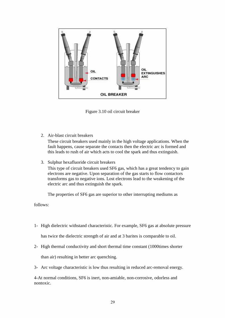
1. Oil circuit breakers
The oil circuit breaker is widely used in industrial fields. This type used the oil
in the process of extinguish the electrical spark when the electric arc
occurrence of bubbles forming working to extinguish the sparks.
Advantages
By connecting several interrupting mechanisms in series, the voltage rating of
the breaker can be increased.
By careful design the interrupting capacity rating can be increased up to
26,000 MVA.
Quiet operation
Disadvantages
The breaker contains flammable oil, consequently should be located outdoors.
Oil breakdown at high temperatures forms carbon which gets dissolved in the
oil. This increases the oil conductivity. To keep the oil insulating properties at
an acceptable level, it must be purified after a predetermined number of
breaker operations. This requires oil treatment equipment on site.
may become an environmental hazard if spillage occurs
29
Figure 3.10 oil circuit breaker
2. Air-blast circuit breakers
These circuit breakers used mainly in the high voltage applications. When the
fault happens, cause separate the contacts then the electric arc is formed and
this leads to rush of air which acts to cool the spark and thus extinguish.
3. Sulphur hexafluoride circuit breakers
This type of circuit breakers used SF6 gas, which has a great tendency to gain
electrons are negative. Upon separation of the gas starts to flow contactors
transforms gas to negative ions. Lost electrons lead to the weakening of the
electric arc and thus extinguish the spark.
The properties of SF6 gas are superior to other interrupting mediums as
follows:
1- High dielectric withstand characteristic. For example, SF6 gas at absolute pressure
has twice the dielectric strength of air and at 3 barites is comparable to oil.
2- High thermal conductivity and short thermal time constant (1000times shorter
than air) resulting in better arc quenching.
3- Arc voltage characteristic is low thus resulting in reduced arc-removal energy.
4-At normal conditions, SF6 is inert, non-amiable, non-corrosive, odorless and
nontoxic.
30
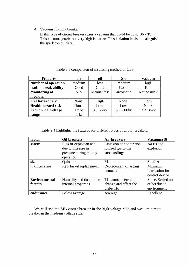
4. Vacuum circuit a breaker
In this type of circuit breakers uses a vacuum that could be up to 10-7 Tor.
This vacuum provides a very high isolation. This isolation leads to extinguish
the spark too quickly.
Table 3.3 comparison of insulating method of CBs
vacuum Sf6 oil air Property
high Medium low medium Number of operation
Fair Good Good Good "soft " break ability
Not possible automatic Manual test N/A Monitoring of
medium
none None High None Fire hazard risk
None Low Low None Health hazard risk
3.3_36kv 3.3_800kv 3.3_22kv Up to
1 kv Economical voltage
range
Table 3.4 highlights the features for different types of circuit breakers.
Vacuum/sf6 Air breakers Oil breakers factor
No risk of
explosion
Emission of hot air and
ionized gas to the
surroundings
Risk of explosion and
due to increase in
pressure during multiple
operation
safety
Smaller Medium Quite large size
Minimum
lubrication for
control device
Replacement of arcing
contacts
Regular oil replacement maintenance
Since. Sealed no
effect due to
environment
The atmosphere can
change and effect the
dielectric
Humidity and dust in the
internal properties Environmental
factors
Excellent Average Below average endurance
We will use the SF6 circuit breaker in the high voltage side and vacuum circuit
breaker in the medium voltage side.

31
3.7.4.2 Auto recloser
Is a self-controlling circuit breaker equipped with mechanism to being able to
reconnect the circuit after separating because of a fault in the system.
3.7.4.3 Current transformer CT
This type of transformer is used within the system of equipment protection. This
transformer works to step down the current that flowing in it for measurement processes
and also protect protection devices where this transformer connect is series with an
electrical system.
3.7.4.4 Voltage transformer VT
Like the current transformer, this transformer works to step down the voltage
between its parties for different measurement processes where the transformer is
connected in parallel with the system.
Figure 3.11 voltage transformer

32
3.7.4.5 Surge arrester
Surge arresters are equipment used to eliminate the sudden impact of the lightning
on the system.
Surge arresters used to protect a variety of devices and equipment in the transmission
system such as transformers.
3.7.4.6 Relays
Relays are developed and installed to protect the lines. The transmission line protection Relays, in the industry, are based on the fundamental frequency components of the voltages and currents.
Principle of Operation
The basic circuit of a simple protection system can be shown as in Figure:
Figure 3.12 principle operation of relay
Where;
1. Protective relay.
2. Circuit breaker (CB).
3. Current transformer (CT).
4. Voltage transformer (VT)
5. Coil of tripping the CB.

33
6. Battery.
7. Auxiliary switch.
8. Circuit of tripping the CB
Protection zone:
As mentioned before, the aims of the power system is to generate, transmit, and
distribute the electrical energy, these aims need several equipment such as generators,
transformers, transmission lines, etc. all these equipment are important so we have to
protect it to provide a continuity and safety supplying. We cannot protect it randomly,
so we divide the system into zones each zone called protection zone.
The figure below shows a simple power system divided into protection zones.
Figure 3.13 protection zones
3.7.4.7 Differential protection
This protection system is use the current difference as criteria. The differential
protection system consisting of:
1. Current transformer (CT).
2. Relay.
The differential protection is used for the very high devices cost such as power
transformer which have rating higher than 5MVA because the cost of this system is
very high and there are two type of this protection:
34
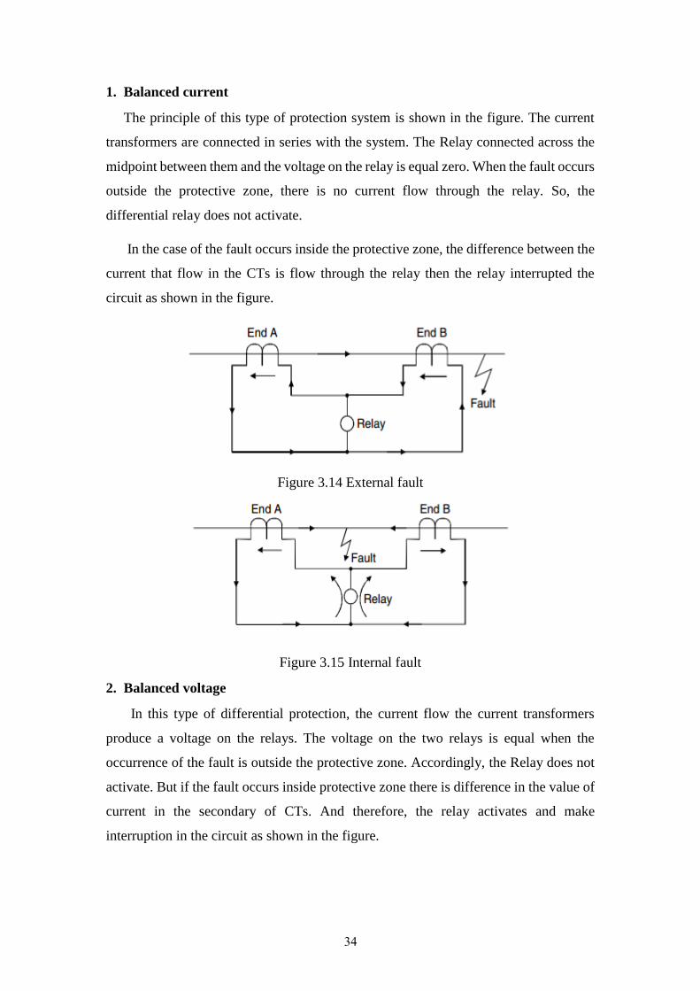
1. Balanced current
The principle of this type of protection system is shown in the figure. The current
transformers are connected in series with the system. The Relay connected across the
midpoint between them and the voltage on the relay is equal zero. When the fault occurs
outside the protective zone, there is no current flow through the relay. So, the
differential relay does not activate.
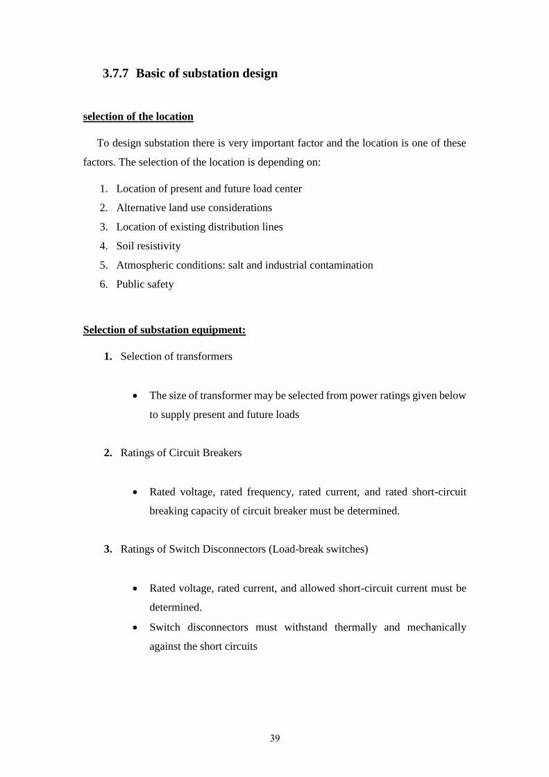
In the case of the fault occurs inside the protective zone, the difference between the
current that flow in the CTs is flow through the relay then the relay interrupted the
circuit as shown in the figure.
Figure 3.14 External fault
Figure 3.15 Internal fault
2. Balanced voltage
In this type of differential protection, the current flow the current transformers
produce a voltage on the relays. The voltage on the two relays is equal when the
occurrence of the fault is outside the protective zone. Accordingly, the Relay does not
activate. But if the fault occurs inside protective zone there is difference in the value of
current in the secondary of CTs. And therefore, the relay activates and make
interruption in the circuit as shown in the figure.

35
Figure 3.16 External fault
Figure 3.17 Internal fault
3.7.5 Requirements of protection system
A. Sensitivity
It means the ability of the protection system to detect all faults and abnormal
conditions in the protective zone where the detection needed for the minimum
fault current. In this requirement, there are three cases:
B. Selectivity:
The circuit breaker must be able to detect and isolate the fault item only.
C. Fast operating:
It means the ability of the protection system to isolate the faulty part quickly,
which leads to minimize the effect of the fault and increase the stability of the
power system.

36
D. Reliability:
It means the dependability, in other word we can depends in the protection
system in all cases such as the arc rare, and it must operate even after years of
operation.
E. Economical
It means obtaining the maximum protection with lower cost, but we have to use
a high-quality protection devices which means more cost needed.
F. Simplicity
The protection system must be simple to help us during maintenance, but
the protection level increase the complexity of the protection system.
In summary, the basic function of protection is to detect faults and to clear them as soon as possible. It is also important that in the process the minimum amount of equipment should be disconnected.
Faults cause large amounts of currents to flow in the components that would burn out if current flows are not promptly interrupted. The voltages of the faulted phases decrease on the occurrence of a fault.
3.7.6 Substation
Substation planning considers the location, size, voltage, sources, loads, and
ultimate function of a substation. If the planning process was not based on scientific
foundations, it leads to high cost of establishing the plant and also a lot of problems that
need to find solutions.
The substation may be categorized as:
1. Distribution Substations

37
A distribution substation is a combination of switching, controlling, and voltage
step-down equipment.
2. Switching Substations
A switching substation is a combination of switching and controlling equipment
arranged to provide circuit protection and system switching flexibility.
3. Transmission Substations
A transmission substation is a combination of switching, controlling, and
voltage step-down equipment arranged to reduce transmission voltage to sub
transmission voltage for distribution of electrical energy to distribution
substations. Transmission substations frequently have two or more large
transformers.
Transmission Substations
Transmission substations are usually characterized by primary and secondary
voltages of 161 kV to 33 kV. The transmission substation has distribution substations
and large loads, reliability of service and flexibility of operation are extremely
important. Facilities normally allow equipment maintenance without circuit
interruption. Multiple bus arrangements and extensive use of circuit breakers for
switching provide added system flexibility.
Figure 3.18 Basic Transmission Substation
Power circuit breakers are included in the two transmission circuits to help prevent
complete substation shutdown for line faults. The circuit breakers have disconnected
switches on both source and load sides to permit isolation during maintenance or other

38
periods requiring complete deenergization. These switches are normally of the three-
pole, single-throw, group-operated type, mounted on separate stands.
The power transformers commonly used are three-phase autotransformers, usually with
tertiary windings. Three-phase two-winding transformers are used when phase
relationships have to be sustained between the primary and the secondary systems. The
disconnect switches on the low-voltage sides of the power transformers allow de-
energization of one transformer while maintaining service to both low-voltage circuits
from the other transformer.
The components of substation:
1. Power transformers
2. Current transformers & Voltage transformers
3. Circuit Breaker
4. Surge Arresters
5. Bus bars
6. Isolators
7. Potential transformer
8. Wave trap
9. Insulator
10. Earth switch
11. Earthing system
12. Control panel
13. Cables
14. Capacitors
15. Autorecloser
39
3.7.7 Basic of substation design
selection of the location
To design substation there is very important factor and the location is one of these
factors. The selection of the location is depending on:
1. Location of present and future load center
2. Alternative land use considerations
3. Location of existing distribution lines
4. Soil resistivity
5. Atmospheric conditions: salt and industrial contamination
6. Public safety
Selection of substation equipment:
1. Selection of transformers
• The size of transformer may be selected from power ratings given below
to supply present and future loads
2. Ratings of Circuit Breakers
• Rated voltage, rated frequency, rated current, and rated short-circuit
breaking capacity of circuit breaker must be determined.
3. Ratings of Switch Disconnectors (Load-break switches)
• Rated voltage, rated current, and allowed short-circuit current must be
determined.
• Switch disconnectors must withstand thermally and mechanically
against the short circuits

40
4. Ratings of Isolators (Disconnectors)
• Rated voltage, rated current, and allowed short-circuit current must be
determined
• Switch disconnectors must withstand thermally and mechanically
against the short circuits
5. Characteristics of Voltage Transformers
6. Characteristics of Current Transformers

41
Chapter 4 : Substation design
4.1 The proper scheme of the substation:
Double breaker–double bus
We choose The double breaker–double bus configuration consists of two main
buses, each normally energized. Electrically connected between the buses are two
circuit breakers and, between the breakers, one circuit, Two circuit breakers are
required for each circuit.
In the double breaker–double bus configuration, any circuit breaker can be
removed from service without interruption of any circuits. Faults on either of the main
buses cause no circuit interruptions. Circuit breaker failure results in the loss of only
one circuit.
Figure 4.1

42
Disadvantages:
Advantages:
1. This configuration carries a high cost. 1. Flexible operation
2. Two circuit breakers are required for
each circuit
2. Very high reliability
3. Isolation of either main bus for
maintenance without disrupting service
4. Isolation of any circuit breaker for
maintenance without disrupting service
5. Double feed to each circuit
6. No interruption of service to any
circuits from bus fault
7. Loss of only one circuit for breaker
failure
8. All switching with circuit breakers
Table 4.1 advantage and disadvantage for double breaker double bus
And according to a high cost this configuration costs 190% with respect to the
cheapest one single breaker single bus (100%) .
4.2 Power transformer:
with a power range from Siemens power transformers with medium range We use
. 250 MVA and a voltage 161/33 KVto 12
• Transformer design according to national and international standards (IEC/ANSI)
with or without voltage regulation
• 3-phase or 1-phase .
• Tank-attached radiators or separate radiator bank .

43
4.2.1 Cooling system:
The necessity of not exceeding the generally permissible maximum heating and
of avoiding hot spots in the transformer require the cooling system to be dimensioned
accordingly. Various methods of cooling can be used depending on the individual
service conditions to guarantee reliable and problem-free operation over many years.
The most noteworthy are the ONAN, ONAF, OFAF oil-air cooling and OFWF oil-
water cooling systems. The radiator banks and oil-air and oil water coolers can be
attached to the transformer or installed separately.
The transformers larger than 10,000 kVA can include up to two stages of cooling.
Each stage of cooling increases the capacity of the transformer by a fixed percentage
of the base rating for transformers above 10,000 kVA, additional stages of cooling
may be used to increase the continuous kVA rating of the transformer by 33 percent
per stage.
4.2.2 Temperatures:
transformer design is based on ambient temperatures of 40°C maximum, 30°C
average over 24 hours, and –20°C minimum. And this is suitable
with our environment which want to design .
4.2.3 Capacity:
Depending on the load growth (2010-2040) the capacity of step down power
transformers (161 / 33) KV.
Nablus capacity is 112 MVA so , according to standard capacity rating available we
choose two transformers with capacity 50 MVA and one transformer with capacity 12
MVA and.
Tulkarm capacity is 70 MVA so , according to standard capacity rating available we
choose two transformers with capacity 25MVA and one transformer 20MVA.
Jenin capacity is 60 MVA so , according to standard capacity rating available we
choose three transformers with capacity 20 MVA.

44
4.2.4 Taps:
Because of a drop in voltage we should change in regulator taps to save the
voltage in desirable range of supply .
4.2.5 Impedance :
Transformer impedance affects transformer voltage regulation, efficiency, and
magnitude of through short-circuit currents. Both regulation and efficiency are
generally improved with lower impedance.
Table: 4.2 the impedances% of the transformers
4.2.6 Protection
we use ABB differential relay to protect power transformer at the substation.
I = 𝑠
√3∙𝑉
I1 – I2 = m I1 + I2
2
Figure 4.2
Impedance % Transformer rating MVA
9.5 50
9.5 25
9.5 20
9.5 12

45
4.3 Substation insulator :
We use Porcelain in our project that is made of ceramic material and it was
widely used in all Over Head Transmission Line with different voltages because of its
efficiency and price comparing to the other one. The main disadvantage of this type is
that it needs frequently cleaning from the accumulated dust on it because this dust
reduces the insulation efficiency.
To achieve the necessary electrical characteristics, a number of suspension
insulators are strung together in series. It is important to coordinate the insulation
characteristics of suspension insulator strings with the insulation systems of other
substation equipment and the characteristics of various insulation protective devices.
The quantity of suspension insulators chosen for a particular application should be
large enough to prevent unnecessary flashovers. Over insulation, however, can result
in flashovers occurring from phase to phase rather than from phase to ground.
Consequently, the quantity of insulators should be small enough that all flashovers
occur to ground. The table 4.3 and table 4.4 show the properties of this insulator.
Typical Voltage, Kv 161
Length (mm) 1458
No. of Sheds 18
Dry Arc Distance (mm) 1245
Leakage Distance (mm) 3150
60 Flashover ANSI /WET 430
Critical Flashover ANSI /NEGATIVE 865
Net Weight (Kg) 20.4
Table 4.3 insulator properties for 161 kV

46
33 Working voltage kV
36 Highest voltage system kV
580 Creepage distance mm
90 Power frequency kV /WET
195 Impulse kV /NEGATIVE
75 One minute power frequency kV /WET
27 Visible discharge test kV
180 Power frequency punture kV
5.5 Net weight approx. Kg
2 Content of each package NOS.
Table 4.4 insulator properties for 33 kV
4.4 Power circuit breaker :
circuit breaker is a device that closes and interrupts (opens) an electric circuit
between separable contacts under both load and fault conditions, the power circuit
breaker is limited to circuit breakers rated 1000 volts and above.
circuit breaker 6 In our project we will use SF
4.4.1 Ratings:
1. Line to line primary voltage (rms) = 161 kV
Line to line secondary voltage (rms) = 33 kV
2. Rated Maximum Voltage: is the maximum voltage for which the circuit
breaker is designed and is also the upper limit for operation on an electric
system.
Rated Max. voltage (rms)= 170 kV, 38 kV (According to available standard) .
3. Current:
Main circuit breaker for transmission line :
0.5 𝐺𝑊
√3∗161𝐾𝑉∗1= 1975𝐴=tI
47
The safety factor for circuit breaker is 1.25 the current equal :
×1975 = 2243.75 𝐴=1.25tCBI
We use over current relay to protect the transmission line system .
In the substations :
According to the transformers in Nablus 50 MVA and 12 MVA:
In the primary system :
50𝑀𝑉𝐴
√3∗161𝐾𝑉= 180𝐴=P1I
And according to safety factor for circuit breaker 1.25 the current equal :
×180 = 225𝐴=1.25PCB1I
12𝑀𝑉𝐴
√3∗161𝐾𝑉= 43 𝐴=2pI
×43 = 53.75 𝐴=1.25PCB2I
In the secondary system :
50𝑀𝑉𝐴
√3∗33𝐾𝑉= 438𝐴=1sI
×438 = 547.5 𝐴=1.25CB1sI
=12𝑀𝑉𝐴
√3∗33𝐾𝑉= 210 𝐴2s I
×210 = 262.5 𝐴=1.25CB2sI
the load circuit breaker :
depending on the scheme double breaker double bus we have four feeders , each
feeder with 28 MVA . So the current of the load equal :
28 𝑀𝑉𝐴
√3∗33𝐾𝑉 = 490𝐴=1LI

48
×490 = 612.5 𝐴=1.25CBL1I
The transformers in Tulkurm 25MVA and 20MVA:
In the primary system :
25𝑀𝑉𝐴
√3∗161𝐾𝑉= 90 𝐴=P 3I
×90 = 112.5𝐴=1.25PCB3I
20𝑀𝑉𝐴
√3∗161𝐾𝑉= 72 𝐴=p4I
×170 = 90 𝐴=1.25CBP4I
In the secondary system :
A43825𝑀𝑉𝐴
√3∗33𝐾𝑉==S 3I
×438 = 547.5𝐴=1.25CBS3I
20𝑀𝑉𝐴
√3∗33𝐾𝑉= 350 𝐴=S4I
×350 = 437.5𝐴=1.25CBS4I
the load circuit breaker :
depending on the scheme double breaker double bus we have four feeders , each
feeder with 17.5 MVA . So the current of the load equal :
17.5𝑀𝑉𝐴
√3∗33𝐾𝑉 = 306.5𝐴=2LI
×306.5 = 383.1𝐴=1.25CBL2I
The transformer in jenin 20 MVA :
In the primary system :

49
20𝑀𝑉𝐴
√3∗161𝐾𝑉= 72𝐴=P5I
×72 = 90𝐴=1.25PCB5I
In the secondary system :
20𝑀𝑉𝐴
√3∗33𝐾𝑉= 350𝐴=S5I
×350 = 437.5 𝐴=1.25CBS5I
the load circuit breaker :
depending on the scheme double breaker double bus we have four feeders , each
feeder with 15 MVA . So the current of the load equal :
15𝑀𝑉𝐴
√3∗33𝐾𝑉 = 262.7𝐴=3LI
×262.7 = 328.37𝐴=1.25CBL3I
4.4.2 Working of SF6 Circuit Breaker :
operation stored in a high pressure reservoir. Duringgas was compressed and 6SF
arc in this highly compressed gas is released through the circuit breaker 6of SF
breaker and collected to relatively low pressure reservoir and then it is pumped back
to the high pressure reservoir for re utilizer. In buffer type design, the arc energy is
utilized to develop pressure in the arcing chamber for arc quenching.
4.4.3 Arc quenching in SF6 circuit breaker :
gas at rated pressure. There are two fixed contact 6breaker is filled with SFThe
fitted with a specific contact gap. A sliding cylinder bridges these to fixed contacts.
The cylinder can axially slide upward and downward along the contacts. There is one
stationary piston inside the cylinder which is fixed with other stationary parts of the
circuit breaker, in such a way that it cannot change its position during the 6SF
50
movement of the cylinder. As the piston is fixed and cylinder is movable or sliding,
the internal volume of the cylinder changes when the cylinder slides. During opening
of the breaker the cylinder moves downwards against position of the fixed piston
gas 6hence the volume inside the cylinder is reduced which produces compressed SF
inside the cylinder. The cylinder has numbers of side vents which were blocked by
upper fixed contact body during closed position. As the cylinder move further
downwards, these vent openings cross the upper fixed contact, and become unblocked
gas inside the cylinder will come out through this vents in 6and then compressed SF
high speed towards the arc and passes through the axial hole of the both fixed
During closing of the gas. 6contacts. The arc is quenched during this flow of SF
circuit breaker, the sliding cylinder moves upwards and as the position of piston
remains at fixed height, the volume of the cylinder increases which introduces low
pressure inside the cylinder compared to the surrounding. Due to this pressure
gas from surrounding will try to enter in the cylinder. The higher 6difference SF
pressure gas will come through the axial hole of both fixed contact and enters into
cylinder via vent and during this flow; the gas will quench the arc.
4.5 Earthing switch:
Earthing switch connect the live parts/ line conductors and earth. This switch is
normally open.
Earthing switch is used to earth the live parts during maintenance and during
testing. During maintenance although circuit is open still there are some voltages on
line, due to which capacitance between line and earth is charged.
Before proceeding to maintenance work the voltage s discharged to earth, by closing
the earth switch.
1. Maintenance Earthing Switch: These are two or three pole units with a manual
operating mechanism.
2. High Speed Earthing Switch: These are operated by spring energy. Spring is
charged by motor-mechanism.
Earthing switch parts:
1- Moving contact.
2- Operating lever.
3- Position indicator.

51
Fig4.3: Closed
position Fig4.4: open position
In systems where the object is fed from double-breaker, it is more practical to use a
freestanding earthing switch at the common connection point to the object (Figures
4.5). This is because the purpose of the earthing switch is to earth the connected
object (line/transformer, etc.) and not the circuit breaker or other high voltage
equipment.
Remote operation of the earthing switches is recommended and a motorized earthing
switch should thus be used.
Fig. 4.5: Double Breaker

52
4.6 Substation Earthing System (Grounding System) [15]
Substation grounding is a critical part of the overall electric power system. It is
designed to not only provide a path to dissipate electric currents into the earth without
exceeding the operating limits of the equipment, but also provide a safe environment
for any people that are in the vicinity.
The grounding system in substation is very important to:
1) To ensure safety to personnel in substations against electrical shocks.
2) To provide the ground connection for connecting the neutrals of stat connected
transformer winding to earth (neutral earthing).
3) To discharge the over voltages from overhead ground wires or the lightning
masts to earth. To provide ground path for surge arresters.
4) To provide a path for discharging the charge between phase and ground by
means of earthing switches.
5) To provide earth connections to structures and other non-current carrying
metallic objects in the sub-station (equipment earthing).
The IEEE standard 80-2000 describes conditions that accidental shock may develop
as follows:
1) Relatively high fault current to ground in relation to the area of ground system
and its resistance to remote earth.
2) Soil resistivity and distribution of ground currents such that high potential
gradients may occur at points at the earth’s surface.
3) Presence of an individual at such a point, time, and position that the body is
bridging two points of high potential difference.
4) Absence of sufficient contact resistance or other series resistance to limit
current through the body to a safe value under circumstances a) through c).
5) Duration of the fault and body contact, and hence, of the flow of current
through a human body for a sufficient time to cause harm at the given current
intensity.

53
Input Data for the Grounding design:
Average Soil resistivity
.m57.4
Fault current split Factor
0.6
Current
1794A
Crushed rock layer inside
sub
0.1016m
Resistivity of crushed
Rock layer
.m2500
Grid buried 18”
0.4572m
Switch Yard operator
>50kg
fCurrent Division Factor S
0.6
Soil location Type
Uniform
Length in X direction
40 m
Projection Factor
20%
Length in Y direction
30 m
Shock Duration
0.5s
Ambient Temperature
40°C
Fault duration
0.5s
Grid Shape
Rectangular
Table 4.5 input data for grounding design
4.6.1 Field Data
The Area for the substation is (40 x 30) m, with assumption of average soil
resistivity of 57.4 .m .[15]
4.6.2 Obtaining the Conductor Size
Calculation of ground fault
If = 3I =3×8970 =26910 A (4.1)
where X/R is assumed to be 10.

54
Adding the current protection factor with growth factor of 20%, the ground fault
current is computer as follows:
If = 3I= 32292 A.
Decrement factor(DF) Fault duration(tf)
X/R=40 X/R=30 X/R=20 X/R=10 Cycles at 60 Hz Seconds
1.688 1.675 1.648 1.576 0.5 0.008
1.515 1.462 1.378 1.232 3 0.05
1.378 1.316 1.232 1.125 6 0.10
1.232 1.181 1.125 1.064 12 0.20
1.163 1.125 1.085 1.043 18 0.30
1.125 1.095 1.064 1.033 24 0.40
1.101 1.077 1.052 1.026 30 0.50
1.068 1.052 1.035 1.018 45 0.75
1.052 1.039 1.026 1.013 60 1.00
Table 4.6: Df Values (Typical)
(From IEEE Std 80-2000 Table 10. Copyright © 2000.IEEE. All rights reserved)
Decrement factor (Df) : is the tim e delay due to the thermal mass is known as a time
lag.
Using Table 4.5 for the X/R ratio and fault duration given in Table 1, it is found that
the decrement, Df, = 1.026.
Now finding the rms. symmetrical fault current is calculated as follows:
IF = If × Df (4.2)
=32991 A
Assuming the use of copper-clad steel wire at ambient temperature (Ta) of 300 C
with melting temperature of 10840 C, 𝐾𝑓 = 10.45 using Table 4.6.

55
Material Conductivity
(%)
Tma() Kf
Copper annealed soft drawn 100.0 1083 7.00
Copper commercial hard
drawn
97.0 1084 7.06
Copper commercial hard
drawn
97.0 250 11.78
Copper clad steel wire 40.0 1084 10.45
Copper clad steel wire 30.0 1084 12.06
Copper clad steel rod 20.0 1084 14.64
Aluminum EC Grade 61.0 657 12.12
Aluminum 5005 Alloy 53.5 652 12.41
Aluminum 6201 Alloy 52.5 654 12.47
Aluminum clad steel wire 20.3 657 17.20
Steel 1020 10.8 1510 15.95
Stainless clad steel rod 9.8 1400 14.72
Zinc coated steel rod 8.6 419 28.96
Stainless steel 304 2.4 1400 30.05
Table 4.7: Material Constants
The required cross-sectional area in circular mils is computed as follows:
AKcmil = I × Kf × √𝑡𝑐 (4.3)
= 32991x 10.45 x√0.5
=209.4 kcmilK
Converting to 𝐴𝑘𝑐𝑚𝑖𝑙 to 𝑚𝑚2is computed below as follows:
Amm2
=AKcmil .1000
1973.52 = 106.2mm2 (4.4)
Thus, the conductor diameter is equivalent to
d =√4 ×𝐴𝑚𝑚2
𝜋
(4.5)

56
= 12 mm or 1.2Cm or 5\8" .
4.6.3 Touch and Step Criteria
The tolerable touch as step voltages need to be met in order ensure that a safe design
is in place. The lower the maximum touch voltages are, the more challenges are
presented in creating a design that fulfills the necessary requirements
Fig.4.6: Exposure to Step Voltage
Fig.4.7: Step Voltage Circuit
Per IEEE Std, the resistance of a human body is 1000BR .
For step voltage, the limit is:

57
Estep = ( RB + 2Rf ) × IB
Fig. 4.8: Exposure to Touch Voltage
Fig. 4.9: Impedances in Touch Voltage Circuit.
Fig. 4.10: Touch Voltage Circuit.
For touch voltage, the limit is
Etouch = ( RB + 𝑅𝑓
2 ).IB

58
If no protective surface layer is used in the substation, Cs = 1 and ρs=ρ.
If there is metal-to-metal contact, both hand-to-hand and hand-to-feet contact, ρs=0
since the ground is not included in this situation.
For a crushed rock-surfacing layer of 0.01268m, having resistivity of 2500Ω. m
and with the computed soil resistivity of 57.4Ω. m, the reflection factor K is computed
as:
K = 𝜌− 𝜌𝑠
𝜌+ 𝜌𝑠 =
57.4−2500
57.4+2500= −0.9511 (4.6)
For the K= -0.93548. The crushed rock is to be de-rated by a factor of
approximately, Cs, which is computed as:
Cs = 1 - 0.09 ( 1−
𝜌
𝜌𝑠 )
2 ×ℎ𝑠 +0.09 (4.7)
Cs = 1 - 0.09 ( 1−
57.4
2500 )
2 ×0.1016+0.09= 0.07
In the design criteria, the switch operator or the maintenance would be approximate
50kg or heavier.
The step and touch voltages are calculated as follows:
Estep = ( 1000 + 6 × Cs × 𝜌𝑠 ) 0.116
√𝑡𝑠 (4.8)
Estep = ( 1000 + 6 × 0.7 × 2500 )0.116
√𝑡𝑠
= 1866.56 V .
Etouch = ( 1000 + 1.5 × Cs × 𝜌𝑠 ) (4.9)
Etouch = ( 1000 + 1.5 × 0.7 × 2500 )
=594.67 V

59
4.6.4 Design
The design is based on the minimum amount of conductor needed that fulfills the
requirements.
Fig. 4.11: 4 ground rods
Horizontal Mesh conductor spacing (4x10) m.
Vertical Electrode Configuration 4.
Assuming any given area for 40m x 30m the grid burial depth h=3m.
Thus, the grid conductor combined length is
Lc = L1 .LX + L2 .Ly (4.10)
= 4×40 + 11×30
= 490 m
Assuming 4 ground rods of 3 meters long are used:
Buried conductor length =LR= 4 x 3 = 12 m. (4.11)
The total length of buried conductor would be computed as
LT = LC + LR (4.12)
= 490m + 12m

60
= 502m.
4.6.5 Determination of Grid Resistance
For uniform soil, the minimum value of the grounding resistance is approximated
using the following formula:
Rg = 𝜌 ( 𝟏
𝑳𝒕+
𝟏
√𝟐𝟎.𝑨 (𝟏 +
𝟏
𝟏+𝒉 √𝟐𝟎
𝑨
) ) (4.13)
From the previous computations, the length of buried conductor is known to be 1,402
m, having an area A=9000𝑚2.
Rg = 𝜌 ( 𝟏
𝑳𝒕+
𝟏
√𝟐𝟎𝑨 (𝟏 +
𝟏
𝟏+𝒉 √𝟐𝟎
𝑨
) )
= 57.4 (𝟏
𝟓𝟎𝟐+
𝟏
√𝟐𝟎×1200 (𝟏 +
𝟏
𝟏+𝟎.𝟒𝟓𝟕𝟐√𝟐𝟎
𝟏𝟐𝟎𝟎
) )
=0.4849 Ω
h : depth of the grid in meters
4.6.6 Maximum Grid Current IG
Some part of the fault current will flow to the earth through the grounding grid. This
current is called the grid current.
Calculating, IG, using IEEE Std.80-2000 is done as follows:
Ig = If x Sf (4.14)
= 32292 x 0.6 A
where
Ig : rms symmetrical grid current in Amps.
If : rms symmetrical grid fault current in Amps.

61
Sf : fault current division factor.
and
IG = Df . Ig (4.15)
= Df .3 . I0 . Sf
where
IG : is the maximum grid current in Amps
Dg : decrement factor for the duration of the fault .
Ig : rms symmetrical grid current in Amps
IG = 1.026 . 3 . 8970 . 0.6 = 16565.7A.
4.6.7 Ground Potential Rise (GPR)
GPR - Ground potential rise is “the maximum electrical potential that a substation
grounding grid may attain relative to a distant grounding point assumed to be at the
potential of remote earth.” GPR is equal to the maximum grid current times the grid
resistance as defined in the equation below:
GPR = IG . Rg (4.16)
=16565.7 ∙ 0.4849 =8032.7 V
where
Rg : substation ground resistance in ohms
IG : maximum grid current in Amps
Comparing with the touch voltage computed in step 3 which was 594.67 V. The GPR
is far exceeds the safe touch voltage. But to optimize cost, rods can be reduced to
ensure no overspending occurs.

62
4.6.8 Mesh Voltage ( Em )
The mesh voltage is the highest possible touch voltage within a substations grounding
grid. The basis of a safe grounding grid system is the mesh voltage. This includes the
grounding grid inside the substation and outside of the substation fence. For a safe
grounding grid system, the mesh voltage needs to be less than the touch voltage.
The geometric factor , n :
n = na . nb . nc . nd (4.17)
na = 2 ×𝐿𝑐
𝐿𝑝 (4.18)
= 2 ×490
2 ×40 + 2 ×30
= 7.32
nb = √𝐿𝑝
4 × √𝐴 (4.19)
= √140
4 × √1200
= 1.00693
nc = 1 for square and rectangular grids.
nd = 1 for square, rectangular, and L-shaped grids.
n = na . nb . nc . nd
= 7.32 ×1.006 ×1 ×1
= 7.363
The irregularity factor , Ki , can be calculated as follows:
Ki = 0.644 + 0.148 . n (4.20)
= 0.644 + 0.148 × 7.363

63
=1.733
The effective buried length, LM
LM = LC + ( 1.55 + 1.22 ( 𝐿𝑟
√𝐿𝑥2+ 𝐿𝑦2 ))LR (4.21)
where
Lr : total length of each ground rods in meters.
Lc : total length of conductor in the horizontal grid in meters
LR : total length of all ground rods in meters
LM = LC + ( 1.55 + 1.22 ( 𝐿𝑟
√𝐿𝑥2+ 𝐿𝑦2 ))LR
= 490+ ( 1.55 + 1.22 ( 3
√4.402+ 11.302 ))12
=508.64 m
The corrective weighting factor, Kh is defined as follows:
Kh =√1 +ℎ
ℎ0 (4.22)
where
h0 : is the grid reference at depth equivalent to 1
Kh =√1 + ℎ
ℎ0
Kh =√1 + 0.4572
1
= 1.2329
Km, is the geometrical spacing factor for the mesh voltage and is defined as:
Km = 1
2 .𝜋 (ln(
𝐷2
16 .ℎ .𝑑 +
( 𝐷+2.ℎ )
8 .𝐷 .𝑑−
ℎ
4.𝑑 ) +
𝐾𝑖𝑖
𝐾ℎ . ln
8
𝜋(2.𝑛−1 )) (4.23)
where
D : spacing between parallel conductors in meters
d : diameter of grid conductors in meters

64
h : depth of ground grid conductors in meters
Kii : corrective weighting that adjusts effects of inner conductors on the corner
mesh
Kh : corrective weighting factor emphasizing the grid depth effects
Km = 1
2.𝜋 . (ln(
𝐷2
16.ℎ .𝑑+
(𝐷+2 ×ℎ )
8×𝐷 ×𝑑−
ℎ
4 ×𝑑 ) +
𝐾𝑖𝑖
𝐾ℎ . ln (
8
𝜋(2.ℎ−1)) )
= 1
2.𝜋 . (
ln( 52
16×0.4572 × 0.01168+
(5+2 ×0.4572 )
8×5 ×0.01168−
0.4570
4 ×0.011672 )
+1
2.𝜋 ×1.225 . ln (
8
𝜋(2×7.363 −1))
)
= 0.736
The mesh voltage, 𝐸𝑚:
Em= 𝜌 .𝐼𝐺 .𝐾ℎ .𝐾𝑖
𝐿𝑀 (4.24)
where
ρ : resistivity of earth in ohm meters
LM : effective burial length in meters
KM : geometrical spacing factor
Ki : irregularity factor
= 57.4×16565.7 ×0.736 ×1.733
508.64
= 529 Volt.
The effective buried conductor length LS:
𝐿𝑆 = 0.75×𝐿𝐶 + 0.85×𝐿𝑅 (4.25)
= 0.75×502 + 0.85×12
=386.7 m
The step factor , Ks , is defined as follows
𝐾𝑆 = 1
𝜋 (
1
2.ℎ +
1
𝐷+ℎ +
1
𝐷 (1 − 0.5𝑛−2)) (4.26)
where
D : spacing between parallel conductors in meters
h : depth of ground grid conductors in meters
n : geometric factor composed of factors na , nb ,nc and nd

65
𝐾𝑆 = 1
𝜋 (
1
2.ℎ +
1
𝐷+ℎ +
1
𝐷 (1 − 0.5𝑛−2))
= 1
𝜋 (
1
2×0.4571 +
1
5+0.4571 +
1
5(1 − 0.57.363−2))
= 0.46856
The step voltage, Es:
𝐸𝑆 =𝜌 .𝐾𝑆 .𝐾𝑖 .𝐼𝐺
𝐿𝑆 (4.27)
= 57.4×0.46856 ×16565.7×1.733
386.7
= 450.87 Volt.

66
Parts of the Substation :
Apparatus Parts to be Earthed Method of Connection
Power Transformer Transformer tank Connect the earthing bolt on transformer
tank to station earth. Connect the neutral
to earthing system
High Voltage Circuit
Breakers
Operating mechanism, frame Connect the earthing bolt on the frame and
the operating mechanism of Circuit Breaker
to earthing system
Surge Arrester Lower Earth Point To be directly connected to the earth mat
Potential
Transformer
Potential transformer tank,
LV neutral.
Connect the transformer earthing bolt
to earthing system Connect LV neutral of
phase lead to case with flexible copper
conductor
Isolator Isolator frame, operating
mechanism, bedplate
Weld the isolator base frame, connects it to
the bolt on operating mechanism base plate
and station earth.
Current Transformer Secondary winding and metal
case
Connect secondary winding to earthing bolt
on transformer case with a flexible copper
conductor.
Table 4.8 : the earthing method for the parts of the substation
4.7 Isolators
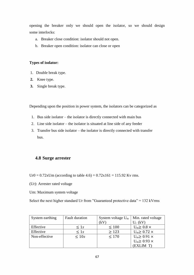
Isolator is a device which is used to isolate the circuit after opening the breaker.
In order to maintenance purpose of breaker we will use isolator. In isolator, we don't
have any arc quenching medium so we cannot eliminate the arc in isolator. So, after
67
opening the breaker only we should open the isolator, so we should design
some interlocks:
a. Breaker close condition: isolator should not open.
b. Breaker open condition: isolator can close or open
Types of isolator:
1. Double break type.
2. Knee type.
3. Single break type.
Depending upon the position in power system, the isolators can be categorized as
1. Bus side isolator – the isolator is directly connected with main bus
2. Line side isolator – the isolator is situated at line side of any feeder
3. Transfer bus side isolator – the isolator is directly connected with transfer
bus.
4.8 Surge arrester
Ur0 = 0.72xUm (according to table 4.6) = 0.72x161 = 115.92 Kv rms.
(Ur): Arrester rated voltage
Um: Maximum system voltage
Select the next higher standard Ur from ”Guaranteed protective data” = 132 kVrms
Min. rated voltage
(kV) r U m System voltage U
(kV)
Fault duration System earthing
≥ 0.8 ×mU ≤ 100 ≤ 1𝑠 Effective
≥ 0.72 ×mU ≥ 123 ≤ 1𝑠 Effective
≥ 0.91 ×mU
≥ 0.93 ×mU
(EXLIM T)
≤ 170 ≤ 10𝑠 Non-effective

68
≥ 1.11 ×mU ≤ 170 ≤ 2 ℎ Non-effective
≥ 1.25 ×mU ≤ 170 >2 h Non-effective
Table 4.9: minimum value of the arrester rated voltage (Ur).
According to table 4.7, a common choice selection for 161 kVrms would be a line
discharge class 2 arrester, PEXLIM R.
This arrester has a Upl /Ur of 2.59. Upl of 342 kVpeak at 10 kA(according to table
4.11).
With a Uwl of 674 kVpeak this would give a protective margin of (674/342-1) x100
= 97 %.
Arrester type Line discharge
class
Energy capability
(2 impulses)
KJ/kV (Ur)
Normal application
range (Um)
EXLIM R 2 5.0 ≤ 170𝑘𝑉
PEXLIM R 2 5.1 ≤ 170𝑘𝑉
EXLIM Q 3 7.8 170 - 420 kV
PEXLIM Q 3 7.8 170 - 420 kV
EXLIM P 4 10.8 362 - 550 kV
PEXLIM P 4 12 362 - 550 kV
HS PEXLIM P 4 15.4 362 - 550 kV
EXLIM T 5 15.4 420 - 800 kV
HS PEXLIM T 5 15.4 420 - 800 kV
Table 4.10. Energy capability of ABB arresters.
Arrester type Nom. Dis-
charge current
(In)
Up/ Ur at 10
kAP
Up/ Ur at 20
kAP
Ups/ Ur
EXLIM R 10 2.59 2.060 at 0.5
kAP
PEXLIM R 10 2.59 2.060 at 0.5
kAP
EXLIM Q 10 2.35 1.981 at 1.0
kAP
PEXLIM Q 10 2.35 1.981 at 1.0
kAP
EXLIM P 20 2.275 2.5 2.020 at 2.0
kAP
PEXLIM P 20 2.275 2.5 2.020 at 2.0
kAP
HS PEXLIM P 20 2.275 2.5 2.020 at 2.0
kAP

69
EXLIM T 20 2.2 2.4 1.976 at 2.0
kAP
Table 4.11. Upl and Ups ratios for ABB arresters
Arrester type Cantilever strength (Nm)
MPDSL PSSL DPSSL
EXLIM R-C 7500 3000 n.a.
EXLIM Q-D 18000 7200 n.a.
EXLIM Q-E 7500 3000 n.a.
EXLIM P-G 18000 7200 n.a.
EXLIM T-P 18000 7200 n.a.
PEXLIM R-Y 1600 n.a. 1000
PEXLIM Q-X 4000 n.a. 2500
PEXLIM P-X 4000 n.a. 2500
HS EXLIM P 28000 n.a. 19000
HS EXLIM T 28000 n.a. 19000
Table 4.12. Permissible strength loading for ABB arresters
With a required creepage distance of 3000 mm. 18.7 mm/kV, (YH161 for PEXLIM
R) housing should be selected.
The type designation of the selected arrester will then be: PEXLIM R132-YH161.
4.9 Instrument transformer
4.9.1 Voltage Transformers
Voltage transformers are used in conjunction with the circuit and equipment
protection, synchronization, and metering schemes. They are normally mounted on
individual or three-position stands. Depending on the bus configuration and the
relaying schemes, the voltage transformers may be positioned near the circuit entrance
positions or adjacent to the buses.
4.9.2 Current Transformers
Current transformers used in both relaying and metering schemes can usually
be located inside major equipment such as power circuit breakers and power
transformers. These current transformers are normally multi-ratio bushing type and
therefore do not require special mounting provisions. In some cases, separately
mounted current transformers may be required, such as for revenue metering
purposes. They are usually installed on individual stands and located as required.

70
In this project, we will use (ABB Instrument Transformers)
Type Name Description
High accuracy
extended range
current/voltage
transformers
KXM
• Substation Class oil-filled (CLASS 0.15S) high
accuracy wide measurement range current/voltage
combined metering transformer for space savings.
• Special design capable of metering accurately over
wide current swing.
• Special series-parallel multi-ratio high accuracy
wide range design available for short lead
times/stock availability (subject to prior sale).
Current for 150 MVA:
In primary :
IP1 = 𝑆
√3×161 𝐾𝑉=
150𝑀𝑉𝐴
√3×161𝐾= 592 𝐴
In secondary :
IS1=𝑆
√3×33𝐾𝑉=
150𝑀𝑉𝐴
√3×33𝐾= 2890 𝐴
Current for 150 MVA:
In primary :
IP2 = 𝑆
√3×161 𝐾𝑉=
50𝑀𝑉𝐴
√3×161𝐾= 180 𝐴
In secondary :
IS2=𝑆
√3×33𝐾𝑉=
50𝑀𝑉𝐴
√3×33𝐾= 877 𝐴
Current for 25 MVA :
In primary :
IP3 = 𝑆
√3×161 𝐾𝑉=
25𝑀𝑉𝐴
√3×161𝐾= 90 𝐴
71
In secondary :
IS3=𝑆
√3×33𝐾𝑉=
25𝑀𝑉𝐴
√3×33𝐾= 900 𝐴
Current for 20 MVA:
In primary :
IP4 = 𝑆
√3×161 𝐾𝑉=
20𝑀𝑉𝐴
√3×161𝐾= 75 𝐴
In secondary :
IS4=𝑆
√3×33𝐾𝑉=
20𝑀𝑉𝐴
√3×33𝐾= 350 𝐴
Current for 12 MVA
In primary :
IP5 = 𝑆
√3×161 𝐾𝑉=
12𝑀𝑉𝐴
√3×161𝐾= 200 𝐴
In secondary :
IS5=𝑆
√3×33𝐾𝑉=
12𝑀𝑉𝐴
√3×33𝐾= 900 𝐴
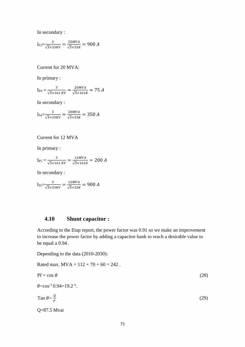
4.10 Shunt capacitor :
According to the Etap report, the power factor was 0.91 so we make an improvement
to increase the power factor by adding a capacitor bank to reach a desirable value to
be equal a 0.94 .
Depending to the data (2010-2030):
Rated max. MVA = 112 + 70 + 60 = 242 .
Pf = cos 𝜃 (28)
𝜃=cos-1 0.94=19.2 °.
Tan 𝜃= 𝑄
𝑃 (29)
Q=87.5 Mvar

72
Q at the system depending on the pdf report = 95.5 Mvar .
QC =95.5 – 87.5 = 8 Mvar .
We make a percentage to distribute the Mvar value according to rated for each city.
QC for Nablus = 4 Mvar .
QC for Tulkarm = 2 Mvar .
QC for Jenin = 2 Mvar .
4.11 Spare capacity system:
We design a spare capacity system for future demand (2015 – 2040) .
Design Requirements:
The spare for Nablus:
Demand Load: MVA :138
Transformers : 150 MVA
Number of Primary Feeds: One transformer.
Overhead or Underground Entry: Overhead with length 1 km to the first joint point.
Secondary Voltage Level: 33KV
The auxiliary for Tulkarm:
Demand Load: MVA :42
Transformer: 50MVA
Number of Primary Feeds: One transformer.
Overhead or Underground Entry: Overhead with length25 km to the first joint point.
Secondary Voltage Level: 33KV

73
The auxiliary for Jenin :
Demand Load: MVA :165
Transformer:150 MVA
Number of Primary Feeds: One transformer.
Overhead or Underground Entry: Overhead with length 30 km to the first joint point.
Secondary Voltage Level: 33KV
4.12 Auxiliary system:
Substation ac auxiliary systems are typically used to supply loads such as:
1. Transformer cooling, oil pumps, and load tap changers
2. Circuit breaker air compressors and charging motors
3. Outdoor device heaters
4. Outdoor lighting and receptacles
5. Control house
a. Lighting and receptacles
b. Heating, ventilating, and air conditioning
c. Battery charger input
d. Water well pump
6. Motor-operated disconnecting switches
Design Requirements:
Demand Load: 7-10 KVA
Transformers: 160 KVA (min. capacity standard rating for transformers)
Number of Primary Feeds: One transformer.
Overhead or Underground Entry: Overhead.
Secondary Voltage Level: 0.4 kV

74
Critical Loads: Some low-voltage loads have to be maintained at all times:
1. Battery chargers which, through the batteries, supply breaker trip and close circuits
as well as communication circuits.
2. Transformer cooling.
3. Power circuit breaker compressors and motors.
4. Trouble light receptacles in the station yard.
5. Security lighting.
6. Breaker control circuits.
7. Fire alarm circuit.
8. Electric heating.
9. Substation automation circuitry.

75
Chapter 5: ETAP
5.1 Introduction
The Windows NT, 4.0 and 2000 platforms provide the highest performance level
for demanding applications, such as large network analysis requiring intensive
computation and online monitoring and control applications.
Windows NT. 4.0. And 2000 also provide the highest levels of reliability,
protection. And security of critical applications. Large PowerStation projects
(approximately 500 buses and larger) should be built and maintained via Windows
NT. 4.0. Or 2000. The Windows 98 and me platforms provide excellent performance
for analysis of small and medium size systems (a few hundred buses) and support a
variety of other popular applications.
Figure 5.1:E-TAP configuration

76
5.2 ETAP Description
5.2.1 Modeling:
1- Virtual reality operation.
2- Total integration of data (electrical, logical, mechanical, and physical attributes).
3- Ring and radial systems.
4- Unlimited isolated subsystems.
5- No system connection limitations.
6- Multiple loading conditions.
7- User access control and data validation.
8- Asynchronous calculations, allow multiple modules to calculate simultaneously.
9- 3-phase and single-phase modeling including panels and subpanels.
5.2.2 Filling data
To run the program we must to enter the data from chapter 2 and chapter 3 in filling
spaces for feeder, transmission line, cable, circuit breaker , transformer, and load.
5.2.3 Feeder
Choose 3 phase connection feeder from info Icon.1-
2 - Choose "in" service feeder from info Icon.
3- Choose swing mode feeder from info Icon.
4- Choose 8 MVA delta connection feeder from short circuit icon.
This steps is clear in fig 4.

77
Figure 5.2:feeder data in E-TAP
5.2.4 Transmission line
Transmission lines for network using 262mm underground cable and transmission
line in domestic region that implemented by the following parameter:
Impedance per conductor**
After filing the needed data from data sheet in to the library of the program,
the program choose atypical value for impedance per conductor per length unit
** Reliability parameter
Shows the reliability of the cable per year per length unit
** Power parameter
Gives the rated current and voltage for the cable
Figure 5.3: Cable data in E-TAP

78
In this part we can put transmission line parameters and how to put the information
of impedance and how to fill the parameter to calculate the sizing of correct
conductor And we see Conductor resistance vs. temperature and Physical parameter
and filling distances between parameters.(clearances between conductors and length
line ).
Figure 5.4: Transmission line data in E-TAP
5.2.5 Transformers
From the data in chapter two and the load growth (2010-2040) for transformer
Specifications and data in chapter three for transformer loading we can fill this
parameter
** rating
In the E-TAP window below shows voltage rating and power rating that needed
for power flow calculation and short circuit analysis.
The rating of the transformer in cities in south west bank. depending at the load
growth (2010-2040)
The max power rating at Nablus = 112MVA.

79
The max power rating at Tulkarm = 70MVA.
The max power rating at Jenin = 60MVA.
Figure 5.5: Transformers data in E-TAP
** Impedance
The program select the zero and positive impedance parameter for X,R, Z.
Reliability parameter **
Shows the reliability of the cable as failure and repair per year.
In this part we can put transmission line parameters and how to put the
information of impedance and how to fill the parameter to calculate the sizing of
correct conductor And we see Conductor resistance vs. temperature and Physical
parameter and filling distances between parameters.(clearances between conductors
and length line ).

80
5.2.6 Load
In the following parameter that concerning load we put the power in MVA for
lumped load rating and choose a value of resistive load between 15% and 20% in
domestic transformer and smaller or larger value of " R " percentage in the industrial
region because of induction and synchronous motors, the E-TAP window show the
parameter that filled for a Sponge factory
Figure5.6 :Load data in E-tab

81
5.2.7 Load flow analysis:
Case study 1:
In this case, the power factor was 0.92 less than 0.94 , so we add capacitor bank
to improve the power factor by provide the reactive power in the net work .
Case study 2:
In this case, we improve the voltage drop by change the taps of the transformer
Fig.5.7: case study 1&2.

82
Fig: 5.8 summary of ETAP pdf.

83
Result and comments on Etap Simulation:
1. We improve the power factor by adding capacitor bank to the circuit
2. Increase the voltage drop after built the circuit by change the taps of
transformer
3. We protect the transmission line by using overcurrent relay and
differential relay to protect the transformer.

84
Conclusion:
In this project, we designed a transmission line system from Huwara to Jenin. The
appropriate design for towers, conductors, insulators has been done as well as for
protection system, considering future loads for the area of the project in the period of
(2015-2040).
we designed substation for each city that the transmission line cross it, and we make
calculations for spare system (2015– 2040), and after getting the specific information
of the network a project synchronization built using E-TAP program, we noticed during
design the substation on ETAP that the power factor needs to improved so, we add
capacitor bank to improve it and to reach the desirable value.

85
References
[1] Rohit Mehta, V.K. Mehta “Principles of Power System”. 2005.
[2] Les Hewitson, Mark Brown and Ben Ramesh, Practical Power Systems Protection,
IDC Technologies, The Netherlands, 2004.
[3] John D. McDonald, ElECTRIC POWER SUBSTATIONS ENGINEERING, The
Electric Power Engineering Handbook, London, 2003.
[4] Glover, J. D., & Sarma, M. S, Power system analysis and design, PWS Pub,
Boston, 1994.
[5] http://www.inmr.com/factors-design-compact-lines-israel/2/
[6] R. Arora J. Roberts, E.O. Schweitzer and E. Poggi. “Limits to the Sensitivity of
Ground Directional and Distance Protection”. 50th Annual Georgia Tech
Protective Relaying Conference, 2001.
[7] Colin Bayliss. “Transmission and distribution electrical engineering”. Newnes,
1999.
[8] Shoaib Khane. “Industrial power system”. Taylor Francis Group, 2008.
[9] S.V.Kulkarni . S.A.Khaparde. “Transformer Engineering Design and Practice”.
MARCEL DEKKER, INC, 2005.
[10] Tom Craig B.Eng. “Safe Switchgear Specifications Application of Low Voltage
Moulded Case Circuit Breakers”
86
[11] Keith Hill. Surge arresters and testing. Doble Engineering Company, 2004.
[12] B. Lacroix and R. Calvas, “Earthing Systems in LV,” Schneider Electric’s
Cahier’s Technique no. 172, March 2002.
[13] N. Jayawarna, M. Lorentzou and S. Papathanassiou, “Re-view of Earthing in a
Micro Grid,” MICROGRIDS Large Scale Integration of Micro-Generation to
Low Voltage Grids project, WORK PACKAGE E, No. 1, 23 April 2004.
[14] Keith Harker (1998). “Power System Commissioning and Maintenance practice.”
London: Institution of Electrical Engineers.
[15] "Design Guide for Rural Substations”, Rural Utilities Service. United States
Department of Agriculture. June 2001.
[16] "IEEE 80-2000 IEEE Guide for Safety in AC Substation Grounding."
[17] http://hubpages.com/technology/Substation-Grounding-Earthing
[18] http://www.studyelectrical.com/2014/05/substation-earthing-system-
grounding.html
[19] "IEEE 81-1983 IEEE Guide for Measuring Earth Resistivity, Ground Impedance,
and Earth Surface Potentials of a Ground System.”
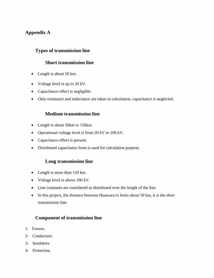
Appendix A
Types of transmission line
Short transmission line
• Length is about 50 km.
• Voltage level is up to 20 kV.
• Capacitance effect is negligible.
• Only resistance and inductance are taken in calculation, capacitance is neglected.
Medium transmission line
• Length is about 50km to 150km.
• Operational voltage level is from 20 kV to 100 kV.
• Capacitance effect is present.
• Distributed capacitance form is used for calculation purpose.
Long transmission line
• Length is more than 150 km.
• Voltage level is above 100 kV.
• Line constants are considered as distributed over the length of the line.
• In this project, the distance between Huawara to Jenin about 50 km, it is the short
transmission line.
Component of transmission line
1- Towers.
2- Conductors.
3- Insulators.
4- Protection.

Appendix B
Towers
Introduction
The main supporting unit of overhead transmission line is transmission tower.
Transmission towers have to carry the heavy transmission conductor at a sufficient safe height
from ground. In addition to that all towers have to sustain all kinds of natural calamities. So
transmission tower designing is an important engineering job where all three basic engineering
concepts, civil, mechanical and electrical engineering concepts are equally applicable.
The design of Power Transmission line tower depends on, type of conductor and Earth-
wire, wind zone, deviation angle and material specification. These towers are galvanized to
protect the steel from corrosion. The galvanizing coating thickness depends on the weather
[1].conditions at the location of tower
Electrical tower parts
A power transmission tower consists of the following parts:
1) Peak of transmission tower
2) Cross arm of transmission tower
3) Boom of transmission tower
4) Cage of transmission tower
5) Transmission Tower Body
6) Leg of transmission tower

7) Stub/Anchor Bolt and Base plate assembly of transmission tower.
The main parts among these are shown in the fig. 1.
Fig. 1 Tower parts
Peak of Transmission Tower
The portion above the top cross arm is called peak of transmission tower. Generally, earth
shield wire connected to the tip of this peak.
Cross Arm of Transmission Tower
Cross arms of transmission tower hold the transmission conductor. The dimension of cross
arm depends on the level of transmission voltage, configuration and minimum forming angle for
stress distribution.

Cage of Transmission Tower
The portion between tower body and peak is known as cage of transmission tower. This
portion of the tower holds the cross arms
Types of transmission towers.
According to different considerations, there are different types of transmission towers.
The transmission line goes as per available corridors. Due to unavailability of shortest
distance straight corridor transmission line has to deviate from its straight way when obstruction
comes. In total length of a long transmission line there may be several deviation points.
According to the angle of deviation there are four types of transmission tower-
1. A – Type tower – angle of deviation 0° to 2°.
2. B – Type tower – angle of deviation 2° to 15°.
3. C – Type tower – angle of deviation 15° to 30°.
4. D – Type tower – angle of deviation 30° to 60°.
As per the force applied by the conductor on the cross arms, the transmission towers can be
categorized in another way-
1. Tangent suspension tower and it is generally A – type tower.
2. Angle tower or tension tower or sometime it is called section tower. All B, C and D types of
transmission towers come under this category.
Apart from the above customized type of tower, the tower is designed to meet special usages
listed below; these are called special type towers:
1. Tension Towers:
The benefits in tensile thread.

2. Suspension Towers.
The towers constitute about 80% of the total number of towers in the font used in the load
conductor.
3. Transposition Towers:
They are exchanged phases on equal distances along the line to occur equal to or equal to the
power capacitance and inductance of the three-line length phases.
4. Angle Towers.
Benefits and change the font path.
5. Crossing Towers:
Used when crossing rivers or at least lines low voltage lines effortlessly.
6. Terminal Towers:
Used at the beginning and end of the transmission line or inlet and outlet transport stations, a
tightening of electrical towers and utility withstand tensile from one side.
Based on numbers of circuits carried by a transmission tower, it can be classified as-
1. Single circuit tower.
2. Double circuit tower.
3. Multi circuit tower.
Poles
Poles used to support the overhead power lines and other public utility like cables and fiber
optic cables.

Poles used for two types of power lines:
a. Transmission lines which carry higher voltage power between substations.
b. Distribution lines which distribute lower voltage power to customers.
Types of poles
1. Wood poles.
2. Concrete poles.
3. Metal poles.
Wood poles
It’s the cheapest type of poles and its made from cedar and pine trees because of its length
and straightness, this type of poles has tall from (25-130) ft. or more as the customer need.
This type is characterized by its flexibility which make it good to hold the conductor, it has
high resistance to pass the current the current and, it easy to structure it, wooden poles handling
by coal tar until it totally saturated and this make the wood age between (40-50) years and
protect it from rot.
Concrete poles
It made in circular clips or square or polygonal (6 or 8) ribs, and it be hollow to decrease its
weight which represents a negative effect when transfer and install the pole, and this hole used to
pass the cable in it, and using iron skewer 8- skewer to increase the strength of the pole.
Concrete poles cost is higher than wood poles and has higher weight so this decrease of use
this type of poles.

This type is characterized that it doesn't affected in mold, rust, fire and it’s the most strength
type of poles and don’t need maintenance.
Metal poles
It made in different lengths and thicknesses, as the durability required, it has many shapes
square or polygonal or circular.
This type of poles flexible as wood poles, and it age between (25-30) years, this age
depends on thickness of Electroplating layer, the cost of this poles is higher than wood poles, the
main reason to use this type of poles because most of people see it more beautiful than other
poles, and it used on highways, streets, courts in lighting.
This type is characterized that it is easy to transfer it, because this poles made as part we can
transfer it easily then assemble it.
Framing
It is the component that installs on poles to carry the conductors, and to keep the needed
space between the conductors.
There are two forms for the framing:
1. Cross arm:
Its hold two conductors on either side, and sometimes its hold three conductors and one of
them on the middle of cross arm.
2. Bracket:
Its hold one conductors and fix it to the side of the pole.
Design span lengths
In transmission line calculations, the following terms are commonly used
1. Basic or normal span
2. Ruling oe equivalent span
3. Average span
4. Wind span
5. Weight span
Basic or normal span
The normal span is the most economic span for which the line is designed over level ground,
so that the requisite ground clearance is obtained at the maximum specified temperature.
Ruling span
The ruling span is the assumed design span that will produce, between dead ends, the best
average tension throughout a line of varying span lengths with changes in temperature and
loading. It is the weighted average of the varying span lengths, calculated by the formula:
Ruling span = √𝐼13 +𝐼23 +..𝐼𝑛3
𝐼1+𝐼2+..𝐼𝑛
Where (l1, l2 ... ln) are the first, second and last span lengths in sections. The erection tension
for any line section is calculated for this hypothetical span.
Tower spotting on the profile is done by means of a sag template, which is based on the ruling
span. Therefore, this span must be determined before the template can be made.
Average span
The average span is the mean span length between dead ends. It is assumed that the
conductor is freely suspended such that each individual span reacts to changes in tension as a

single average span. All sag and tension calculations are carried out for the average span, on this
assumption. Wind span the wind span is that on which the wind is assumed to act transversely on
the conductors and is taken as half the sum of the two spans, adjacent to the support (fig. wind
span and weight span) In order to take full advantage of towers located on elevated ground, it is
usual to allow a wind span of 10 to 15 percent in excess of the normal span. This additional
strength can be used in taking a small angle of deviation on an intermediate tower, where the
actual wind span is less than the design wind span. The angle of deviation to be taken in such
cases is approximately given by:
ɵ =𝑤𝑙
𝜋𝑇×180
Where w = total and load per unit run of span length of all conductor carried by the tower, l =
difference between the wind span used for design and the actual wind span, and T = the total
maximum working tension of all conductors carried by the tower.
Weight span
The weight span is the horizontal distance between the lowest point of the conductors, on the
two spans adjacent to the tower (fig. wind span and weight span) The lowest point is defined as
the point at which the tangent to the sag curve, or to the sag curve produced, is horizontal. The
weight span is used in the design of cross-arms.
Fig. 2 wind span and weight span
Tower configurations
Depending upon the requirements of the transmission system, various line configurations
have to be considered - ranging from single circuit horizontal to double circuit vertical structures
and with single or V strings in all phases, as well as any combination of these.
The configuration of a transmission line tower depends on:
1. the length of the insulator assembly
2. the minimum clearances to be maintained between conductors, and between conductors and
tower
3. the location of ground wire or wires with respect to the outermost conductor
4. the mid-span clearance required from considerations of the dynamic behavior of conductors
and lightning protection of the line
5. the minimum clearance of the lowest conductor above ground level.
The tower outline is determined essentially by three factors: tower height, base width, and top
hamper width.
Minimum permissible ground clearance
For safety considerations, power conductors along the route of the transmission line should
maintain requite clearance to ground in open country, national highways, rivers, railways tracks,
telecommunication lines, other power lines, etc.., as laid down in the Indian Electricity Rules, or
Standards or codes of practice in vogue.

Rule 77(4) of the Indian Electricity Rules, 1956, stipulates the following clearances above
ground of the lowest point of the conductor:
For extra- high voltage lines, the clearance above ground shall not be less than 5.182 meters plus
0.305 meters for every 33,000 volts or part there of by which the voltage of the line exceeds
33,000 volts.
Accordingly, the values for the various voltages, 66kV to 400 kV, are:
66kV - 5.49m
132kV - 6.10m
220kV - 7.01m
400kV - 8.84m
The above clearances are applicable to transmission lines running in open country.
Power line crossings
In crossings over rivers, telecommunication lines, railway tracks, etc.., the following
clearances are maintained:
1. Crossing over rivers
a. Over rivers which are not navigable. The minimum clearance of conductor is specified as
3.05 over maximum flood level.
b. Over navigable rivers: Clearances are fixed in relation to the tallest mast, in consultation
with the concerned navigation authorities.
2. Crossing over telecommunication lines. The minimum clearances between the conductors of a
power line and telecommunication wires are
66 kV - 2,440mm
132 kV - 2,740mm

220 kV - 3,050mm
400 kV - 4,880mm
3. Crossing over railway tracks: The minimum height over the rail level, of the lowest portion of
any conductor under conditions of maximum sag, as stipulated in the regulations for Electrical
Crossings of Railway Tracks, 1963, is given in Table 4.1.
4. Between power lines
a. Between power lines L.T up to 66 kV - and 66 kV line 2.44m
b. Between power lines L.T up to 132 kV - and 132kV line 2.75m
c. Between power lines L.T up to 220kV - and 220kV line 4.55m
d. Between power lines L.T up to 400kV - and 400kV line 6.00m(Tentative)
Spacing of conductors
Considerable differences are found in the conductor spacing's adopted in different countries
and on different transmission systems in the same country.
The spacing of conductors is determined by considerations which are partly mechanical. The
material and diameter of the conductors should also be considered when deciding the spacing,
because a smaller conductor, especially if made of aluminum, having a small weight in relation
to the area presented to a crosswind, will swing out of the vertical plane father than a conductor
of large cross-section. Usually conductors will swing synchronously (in phase) with the wind,
but with long spans and small wires, there is always a possibility of the conductors swinging
non-synchronously, and the size of the conductor and the maximum sag at the center of the span
are factors which should be taken in to account in determining the distance apart at which they
should be strung.
There are a number of empirical formulae in use, deduced from spacing's which have
successfully operated in practice while research continues on the minimum spacing's which
could be employed.

The following formulae are in general use:
1. Mecomb's formula
Spacing in cm = 0.3048V + 4.010 𝐷
𝑤√𝑆
Where V = Voltage in kV,
D = Conductor diameter in cm,
S = sag in cm, and
W = Weight of conductor in kg/m.
2. NESC, USA formula
Horizontal spacing in cm
= 𝐴 + 3.681√𝑆 +𝐿
√2
Where A=0.762 cm per kV line voltage
S = Sag in cm, and
L = Length of insulator string in cm
Offset of conductors (under ice-loading conditions)
The jump of the conductor, resulting from ice dropping off one span of an ice-covered line,
has been the cause of many serious outages on long-span lines where conductors are arranged in
the same vertical plane. The 'sleet jump' has been practically cleared up by horizontally offsetting
the conductors. Apparently, the conductor jumps in practically a vertical plane, and this is true if
no wind is blowing, in which cases all forces and reactions are in a vertical plane. In double
circuit, vertical configuration, the middle conductors are generally offset in accordance with the
following formula:

Offset in cm = 60 + Span in cm / 400
Vertical clearance between ground wire and top conductor
This is governed by the angle of shielding, the angle which the line joining the ground wire
and the outermost conductor makes with the vertical, required for the interruption of direct
lightning strokes at the ground and the minimum midspan clearance between the ground wire
and the top power conductor. The shield angle varies from about 25o to 30o, depending on the
configuration of conductors and the number of ground wires (one or two) provided.
Determination of base width
The base width at the concrete level is the distance between the center of gravity at one corner
leg and the center of gravity of the adjacent corner leg. There is a particular base width which
gives the minimum total cost of the tower and foundations.
Ryle has given the following formula for a preliminary determination of the economic base
width:
B=0.42√𝑀 𝑜𝑟 0.013√𝑚
Where B = Base width in meters,
M = Overturning moment about the ground level in tone-meters,
and M= Overturning moment about the ground level in kg. meters.
The ratio of base width to total tower height for most towers is generally about one-fifth to one-
tenth from large-angle towers to tangent towers.
The following equations have been suggested9, based on the best fit straight line relationship
between the base width B and √𝑀
B=0.0782√𝑀 +1.0

B=0.0691√𝑀 + 0.7
Equations are for suspension and angle towers respectively.
It should be noted that Ryle’s formula is intended for use with actual external loads acting on the
tower whereas the formulae in Equations take into account a factor of safety of 2.0.
Narrow-base towers are commonly used in Western Europe, especially Germany, mainly from
way-leave considerations. British and American practices generally favor the wide base type of
design, for which the total cost, of tower and foundations is a minimum. In the USA, a
continuous wide strip of land called the ‘right of way’ has usually to be acquired along the line
route. In Great Britain, the payments made for individual tower way-leaves are generally
reasonably small and not greatly affected by tower base dimensions. Therefore, it has been
possible to adopt a truly economic base width in both the United States and Great Britain.
A wider taper in the tower base reduces the foundation loading and costs but increases the cost
of the tower and site. A minimum cost which occurs with a tower width, is greater with bad soil
than with good soil. A considerable saving in foundation costs results from the use of towers
with only three legs, the tower being of triangular section throughout its height. This form of
construction entails tubular legs or special angle sections. The three-footing anchorage has
further advantages, e.g., greater accessibility of the soil underneath the tower when the land is
cultivated.
Determination of top hamper width
The width at top hamper is the width of the tower at the level of the lower cross-arm in the case
of barrel type of towers (in double circuit towers it may be at the middle level) and waist line in
the case of towers with horizontal configuration of conductors.
The following parameters are considered while determining the width of the tower at the top
bend line:
1. Horizontal spacing between conductors based on the midspan flashover between the power
conductor under the severest wind and galloping conditions and the electrical clearance of the
line conductor to tower steel work.

2. The sloe of the legs should be such that the corner members intersect as near the center of
gravity (CG) of the loads as possible. Then the braces will be least loaded. Three cases are
possible depending upon the relative position of the CG of the loads and intersection of the tower
legs.
In Case (1) the entire shear is taken up by the legs and the bracings do not carry any stress.
Case (2) shows a condition in which the resultant of all loads O’ is below the inter-section of
tower legs O. The shear here is shared between legs and bracings which is a desirable
requirement for an economical tower design.
In Case (3), the legs have to withstand greater forces than in cases (1) and (2) because the legs
intersect below the center of gravity of the loads acting on the tower. This outline is
uneconomical. The top hamper width is generally found to be about one-third of the base width
for tangent and light angle towers and about 1.35 of the base width for medium and heavy angle
towers. For horizontal configurations, the width at the waistline is, however, found to vary from
1/1.5 to ½.5 of the base width.
Minimum height above ground for overhead line in UK (electricity regulation 1988,
amended 1990)
Nominal system voltage Vn (kV) Clearance (m)
33<Vn<66 6.0
66<Vn<132 6.7
132<Vn<275 7.0
275<Vn<400 7.3

Typical overhead line clearances (based om maximum conductor temperature the load –
EN 50341)
Clearance (m) from line with highest system voltage of:
Clearance consideration 161kV
To ground in unobstructed
countryside
6.2
To rockface or steep slope 3.2
To trees which cannot be climbed 1.2
To trees which can be climbed 2.7
To buildings with fire-resistance
roofs and roofs with slope < 15o to
horizontal
5.2
To buildings with fire-resistance
roofs and roofs with slope > 15o to
horizontal
3.2
Horizontal clearance to buildings 3.2
To fire sensitive installations 11.2
To antennae, lamp posts, etc.
which cannot stoop upon
3.2
Line crossing of minor roads,
railways and waterways
3.2-7.2 depending on nature of roads, railways (e.g.
electrified or not) and waterway (e.g. with structures or not)

[5]Towers kV 161

Appendix C
Conductors
Introduction
Conductor is a physical high to carry electrical energy form one place to other. It is an
important component of transmission and distribution systems. The choice of conductor depends
on the cost and efficiency. An ideal conductor has following features:
1. It has maximum electrical conductivity.
2. It has high tensile strength so that it can withstand mechanical stresses.
3. It has least specific gravity i.e. weight / unit volume.
4. It has least cost without sacrificing other factors.
In early days' copper ‘Cu’ conductors were used for transmitting energy in stranded hard
drawn form to increase tensile strength. But now it has been replaced by aluminum ‘Al’ due to
following reasons:
1. It has lesser cost than copper.
2. It offers larger diameter for same amount of current which reduces corona.
Aluminum also has some disadvantages over copper
1. It has less conductivity.
2. It has larger diameter which increase surface area to air pressure thus it swings more in air
than copper so larger cross arms required which increases the cost.
3. It has lesser tensile strength ultimately larger sag.
4. It has lesser specific gravity (2.71gm/cc) than copper (8.9 gm/cc) cc = cubic centimeter.

The temperature of the conductor increases with increasing heat produced by the current
through it, it is sometimes possible to increase the power handling capacity (uprate) by changing
the conductors for a type with a lower coefficient of thermal expansion or a higher allowable
operating temperature.
P = 𝑰 𝟐×𝑹
Aluminum conductors
1. All Aluminums Conductors (A.A.C.)
1. It has lesser strength and more sag per span length than any other category
Therefore, it is used for lesser span i.e. it is applicable at distribution level.
2. It has slightly better conductivity at lower voltages than ACSR i.e. at distribution level.
3. Cost of ACSR is equal to AAC.
2. All Aluminum Alloy Conductors (A.A.A.C.):
A.A.A.C. is mainly used for overhead lines, in transmission and distribution electrical
networks, having relatively long span. They are also used a messenger to support overhead
electrical cables.
3. Aluminum Conductor Steel Reinforced (A.C.S.R.):
A.C.S.R conductors are widely used for electrical power transmission- over long
distances, since they are ideal for long overhead lines spans. They are- also used as a messenger
for supporting overhead electrical cables.

Figure ACSR Conductor, Aluminum Conductors Steel
4. International Annealed Copper Stand (I.A.C.S)
It is 100 % pure conductor and it is standard for reference.
Structure of Conductor:
An ACSR conductor consists of a couple of wires of steel core which is zinc
Coated. External skin consists of one or more layer of aluminum wires.
Voltage Ratings
Voltage is the electrical potential difference between two points. Voltage is divided into three
different voltage areas which are low voltage, medium voltage and high voltage (extra high
voltage and ultra-high voltage).
.
From 0kv to 1kv Low voltage
From 1kv to 45kv Medium voltage
From 45kv to 300 kv High voltage
From 300kv to 750 kv Extra high voltage
Up to 800 kv Up high voltage

Data sheet for used conductors

Insulators
Introduction
• The overhead line conductors are bare and not covered with any insulating coating or
covering.
• The insulators are the means of insulating medium which keep the line conductor away
from the supporting structure.
• It provides necessary clearance between conductor and metal works.
• Proper selection of overhead line insulator is essential for successful operation of overhead
lines.
types of insulator
1. Pin type insulator
2. Post insulator
3. Suspension type insulators
4. Strain insulators
5. Shackle insulators
1. pin type insulator:
It provides the most economic, simple and efficient method for voltages less than 33KV
It can have fitted on cross arm with the help of pins and conductor is placed in the groove at the
top of insulator and it is tied with the help of copper or aluminum wires.
Pin should be able to with stand the mechanical stress, wind and ice loading
advantages:
• It is cheaper
• Pin insulator can do the work of two suspension insulators
• Since pin insulator rises the conductor above the cross arm so required height of towers is
also less.
disadvantages
• For operating voltage, greater than 33kv, it in uneconomical and size is also bulky.
• Once a pin insulator is failed short circuit can occur.
2. Post insulator
• There are used for supporting the busbars and disconnecting switches in sub stations.
• It is similar to pin type insulator but has metal base and metal cap.
• In this insulator, the porcelain elements are in the form of cones fitting one side the other
and are bonded by special cement.
• Used for voltage up to 33kv.
3. suspension type insulators
• It consists number of porcelain discs flexibly connected in series by metal links in form of
a string.
• In hangs from cross arms and conductor is attached to lower end.
• As there is no pin. we can put any distance between the cross arms and the conductors by
adding a disc
• Number of insulator in a string depends on operating voltages, weather condition, type of
transmission structure and the size of insulator used
• Each unit of suspension insulator for 11kv.
advantages
• It is cheaper for operating voltage above 33kv.
• It one disc is damaged, whole string will need not to be replaced.
• Less mechanical stress.
• The operating voltage can be increased according to demand by adding disc of insulator to
the string.
disadvantages
• Spacing between conductor should be large to allow swing of conductors.
• Height of line supports should be large as conductor is hanged below the cross arms.
4. strain insulators
• At the dead end and corner the line is subjected to great tension.
• To withstand this tension strain insulators are used.
• For voltage, less than 11kv, shackle insulators are used as strain insulators
• For voltage, greater than 11kv suspension (disc) insulators are used.
• The discs of strain are used in vertical plane.
• When the tension is higher as at river spans tower, more string are used in parallel.
5. Shackle insulators
• It is used for low voltage distribution
• Such insulators can be used either in vertical position or horizontal position.
• They are directly fixed to pole with the help bolts.
• The conductor in groove is fixed with soft binding wires.
how to test the electrical insulators:
1-Testing lightning:
a. power frequency dry flash over
The use of effort between the two poles of the separation and then increases the effort for
1 minute until the ionized air around Bazl and broken.
b. power frequency wet flash over
The use of effort between the two poles of the separation effort then sprayed with water
resistance between 9000 increase to 11,000 ohm-on-insulator 45-degree angle provided
that the water does not fall more than 5.0 mm per minute for a period of 30 seconds
2-Hole-voltage tests:
It is fed high voltage and then gradually increase the effort where the hole Bazl happen and is used
by high voltage higher than 30% of the operating voltage
3-Strong test mechanic.
This test uses screw insulators to make sure that the separation is capable of carrying Mosul is
done to add 250% of the load of the separation of conductor, one minute for the separation and be
force in newton's.
4-Strong electrical test
This test is used in insulation comment where this is done to add 250% of the load of the separation
of conductor, one minute for then is used 55% of lightning effort.

5-Test softness of texture
Sample is taken from the separation and then breaks it and put it in a ratio of 1% of the Fuxin
solution under pressure as 150 grams per square centimeters for an hour and then takes out the
sample and note there is no uh scratches or puncture
6-High voltage test
Insulation is placed in the water is then used high voltage for 5 minutes where it should not damage
the insulation
7-Corrosion Testing
Insulating material is placed in the copper phosphate at a temperature of 15 ° C for a minute and
then goes out and cleans the separation and placed the separation time second in the converter and
repeat it 4 times.

References
[1] Rohit Mehta, V.K. Mehta “Principles of Power System”. 2005.
[2] Les Hewitson, Mark Brown and Ben Ramesh, Practical Power Systems Protection, IDC
Technologies, The Netherlands, 2004.
[3] John D. McDonald, ElECTRIC POWER SUBSTATIONS ENGINEERING, The Electric
Power Engineering Handbook, London, 2003.
[4] Glover, J. D., & Sarma, M. S, Power system analysis and design, PWS Pub, Boston, 1994.
[5] http://www.inmr.com/factors-design-compact-lines-israel/2/
[6] R. Arora J. Roberts, E.O. Schweitzer and E. Poggi. “Limits to the Sensitivity of
Ground Directional and Distance Protection”. 50th Annual Georgia Tech
Protective Relaying Conference, 2001.
[7] Colin Bayliss. “Transmission and distribution electrical engineering”. Newnes,
1999.
[8] Shoaib Khane. “Industrial power system”. Taylor Francis Group, 2008.
[9] S.V.Kulkarni . S.A.Khaparde. “Transformer Engineering Design and Practice”.
MARCEL DEKKER, INC, 2005.
[10] Tom Craig B.Eng. “Safe Switchgear Specifications Application of Low Voltage
Moulded Case Circuit Breakers”
[11] Keith Hill. Surge arresters and testing. Doble Engineering Company, 2004.
[12] B. Lacroix and R. Calvas, “Earthing Systems in LV,” Schneider Electric’s
Cahier’s Technique no. 172, March 2002.
[13] N. Jayawarna, M. Lorentzou and S. Papathanassiou, “Re-view of Earthing in a
Micro Grid,” MICROGRIDS Large Scale Integration of Micro-Generation to
Low Voltage Grids project, WORK PACKAGE E, No. 1, 23 April 2004.

[14] Keith Harker (1998). “Power System Commissioning and Maintenance practice.” London:
Institution of Electrical Engineers.