dcs f-15c eagle flight manual
TRANSCRIPT
[F-15C] DCS
BELSIMTEK 1
DCS F-15C EAGLE
Flight Manual

[F-15C] DCS
BELSIMTEK 2
F-15C: DCS Flaming Cliffs is the module of F-15C aircraft for DCS World.
©2014 OOO "BelSimTek"
General discussion forum: http://forums.eagle.ru
[F-15C] DCS
BELSIMTEK 3
TABLE OF CONTENTS
F-15C INTRODUCTION ................................................................................................... 7
F-15 HISTORY ................................................................................................................ 9
ORIGINS ......................................................................................................................... 9
FURTHER DEVELOPMENTS .......................................................................................... 16
MULTISTAGE IMPROVEMENT PROGRAM ................................................................... 21
F-15S ENTER SERVICE ................................................................................................... 22
F-15S IN COMBAT ......................................................................................................... 23
GAME AVIONICS MODE .............................................................................................. 29
NAVIGATION MODE .......................................................................................................... 30
AIR TO AIR MODE ............................................................................................................. 31
F-15C COCKPIT INSTRUMENTS .................................................................................... 34
VERTICAL SITUATION DISPLAY (VSD) .................................................................................... 35
TEWS DISPLAY UNIT ......................................................................................................... 36
MULTI-PURPOSE COLOR DISPLAY (MPCD) WEAPON CONTROL PANEL ....................................... 37
INDICATED AIR SPEED (IAS) AND MACH METER ..................................................................... 38
ANGLE-OF-ATTACK (AOA) INDICATOR .................................................................................. 39
ACCELEROMETER .............................................................................................................. 39
ATTITUDE DIRECTOR INDICATOR (ADI) ................................................................................. 40
HORIZONTAL SITUATION INDICATOR (HSI) ............................................................................. 40
ALTIMETER ...................................................................................................................... 41
VERTICAL VELOCITY INDICATOR (VVI) ................................................................................... 41
TACHOMETER ................................................................................................................... 42
FAN TURBINE INLET TEMPERATURE INDICATORS...................................................................... 42
ENGINE FUEL FLOW INDICATORS .......................................................................................... 43
ENGINE EXHAUST NOZZLE POSITION INDICATOR...................................................................... 43
FUEL QUANTITY INDICATOR ................................................................................................ 44
[F-15C] DCS
BELSIMTEK 4
CABIN PRESSURE ALTIMETER ............................................................................................... 45
CHAFF AND FLARE LIGHTS.................................................................................................... 45
F-15C HUD OPERATING MODES ........................................................................................ 46
Basic F-15C HUD Symbols ........................................................................................ 46
Navigation Mode ..................................................................................................... 47
Gunnery Modes ........................................................................................................ 49
AIM-9M/P Sidewinder "Air-to-Air" Short Range Missile (SRM) Modes.................... 51
Radar-Slaved Mode ................................................................................................. 53
AIM-7M Sparrow "Air-to-Air" Medium Range Missile (MRM) Modes ..................... 55
AIM-120 AMRAAM "Air-to-Air" Medium Range Missile (MRM) Modes .................. 58
Auto ACQuisition (AACQ) Radar Modes ................................................................... 62
AN/APG-63(V)1 RADAR .................................................................................................. 64
Long Range Search (LRS) Mode ............................................................................... 66
Single Target Track (STT) Mode ............................................................................... 68
Track While Scan (TWS) Mode ................................................................................. 69
Home On Jam (HOJ) Mode ....................................................................................... 70
Vertical Scan (VS) AACQ Mode ................................................................................ 71
Bore Sight (BORE) AACQ Mode ................................................................................ 72
AUTO GUNS (GUN) AACQ Mode .............................................................................. 72
FLOOD Mode ............................................................................................................ 73
COUNTERMEASURE SYSTEMS ..................................................................................... 75
AN/ALQ-135 INTERNAL ECM SYSTEM ................................................................................ 75
RADAR WARNING SYSTEMS ......................................................................................... 76
AN/ALR-56C WARNING RECEIVER ..................................................................................... 77
AIR-TO-AIR MISSILES ................................................................................................... 84
MEDIUM RANGE MISSILES .................................................................................................. 86
AIM-120 AMRAAM .................................................................................................. 86
AIM-7 Sparrow ......................................................................................................... 89
CLOSE COMBAT MISSILES ................................................................................................... 91
AIM-9 Sidewinder..................................................................................................... 91
RADIO COMMUNICATIONS AND MESSAGES ............................................................... 94
[F-15C] DCS
BELSIMTEK 5
RADIO COMMANDS ........................................................................................................... 94
RADIO MESSAGES ........................................................................................................... 101
VOICE MESSAGES AND WARNINGS ..................................................................................... 104
THEORETICAL TRAINING ........................................................................................... 107
INDICATED AIR SPEED AND TRUE AIRSPEED .......................................................................... 107
VELOCITY VECTOR ........................................................................................................... 107
ANGLE-OF-ATTACK (AOA) INDICATOR ................................................................................ 107
TURN RATE AND RADIUS OF TURN ...................................................................................... 108
TURN RATE .................................................................................................................... 110
SUSTAINED AND INSTANTANEOUS TURNS ............................................................................. 112
ENERGY CONTROL ........................................................................................................... 112
COMBAT OPERATION BASICS .................................................................................... 114
AIR COMBAT TACTICS ...................................................................................................... 114
Target Search ......................................................................................................... 114
Beyond Visual Range (BVR) Combat ...................................................................... 115
Maneuvers ............................................................................................................. 115
Gun Employment in Air Combat ............................................................................ 116
Air-to-Air Missile Tactics ........................................................................................ 118
MISSILE BREAKAWAY ....................................................................................................... 118
F-15C FLIGHT DYNAMICS ........................................................................................... 124
Take-Off ................................................................................................................. 124
Climb ...................................................................................................................... 125
Inflight .................................................................................................................... 125
Approach................................................................................................................ 126
Go Around .............................................................................................................. 126
Landing .................................................................................................................. 126
MANEUVERABILITY OF THE F-15C EAGLE ................................................................... 126
Basic Concept of Aircraft Maneuverability ............................................................ 126
ENVELOP OF ALTITUDES AND AIRSPEEDS .............................................................................. 127
Envelope Boundaries .............................................................................................. 127
Flight at Stratospheric Altitudes ............................................................................ 129

[F-15C] DCS
BELSIMTEK 6
Flight at Static Ceiling Altitudes ............................................................................. 129
Lateral and Directional Control Characteristics ..................................................... 129
Slow Speed Flight ................................................................................................... 130
High AOA Horizontal Flight .................................................................................... 130
Tailslide .................................................................................................................. 130
Flight at High Airspeeds and High AOA ................................................................. 131
Terrain Following Flight ......................................................................................... 131
G LOADS ..................................................................................................................... 132
Normal Load Factor ............................................................................................... 132
Maximum Normal (Instantaneous) G Load ........................................................... 133
Normal (Sustained) Thrust-Limited G Load ............................................................ 134
Maximum Normal (Sustained) Thrust-Limited G Loads ......................................... 134
Longitudinal G Load ............................................................................................... 135
EFFECTS OF EXTERNAL FACTORS ON PRIMARY MANEUVERABILITY CHARACTERISTICS ...................... 136
Weight ................................................................................................................... 136
External stores ....................................................................................................... 137
Atmospheric conditions ......................................................................................... 137
F-15C CHECK LISTS .................................................................................................... 139
START UP ...................................................................................................................... 139
TAXI AND TAKEOFF .......................................................................................................... 139
NAVIGATION .................................................................................................................. 140
LANDING ....................................................................................................................... 140
AIR-TO-AIR WEAPON EMPLOYMENT .................................................................................. 141
AIM-120 AMRAAM ................................................................................................ 141
AIM-7 Sparrow ....................................................................................................... 141
AIM-9 Sidewinder................................................................................................... 142
M-61 Gun ............................................................................................................... 142
SUPPLEMENTS .......................................................................................................... 145
ACRONYM LIST ............................................................................................................... 145

[F-15C] DCS
BELSIMTEK 7
F-15C INTRODUCTION The F-15C has often been labeled as the greatest fighter aircraft in the world. Designed to counter the exaggerated capabilities of the Soviet MiG-25 Foxbat, the F-15C has been the backbone of U.S. air defense for three decades. The F-15C, equipped with improved avionics and weapons over the original F-15A, has scored over 100 air-to-air victories in the service of Israel, Saudi Arabia, and the U.S. without suffering any losses.
Figure 1. The F-15C
The F-15C rules the Beyond Visual Range arena (BVR). No slouch in a dogfight, the F-15C excels at finding targets, positively identifying them as hostile, and engaging them with AIM-120C AMRAAM missiles before the enemy can respond.
The F-15's versatile pulse-Doppler radar system can look up at high-flying targets and down at low-flying targets without being confused by ground clutter. It can detect and track aircraft and small high-speed targets at distances beyond visual range down to close range, and at altitudes down to tree-top level. The radar feeds target information into the central computer for effective weapons delivery. For close-in dogfights, the radar automatically acquires enemy aircraft, and this information is projected on the head-up display.
The Eagle can also be deadly in the close-in dogfight. The AIM-9M Sidewinder, a reliable weapon that has soldiered on since the 1960’s, does not have the high off-boresight capability of recent Russian heat-seeking missiles. F-15C drivers should generally favor the higher-speed "energy fight" in favor of the low-speed turning duel, especially against nimble adversaries. However, in a slow-speed fight, the Eagle's large rudders are a powerful tool in the hands of a skilled pilot.
[F-15C] DCS
BELSIMTEK 8
F-15 HISTORY F-15 HISTORY
[F-15C] DCS
BELSIMTEK 9
F-15 HISTORY
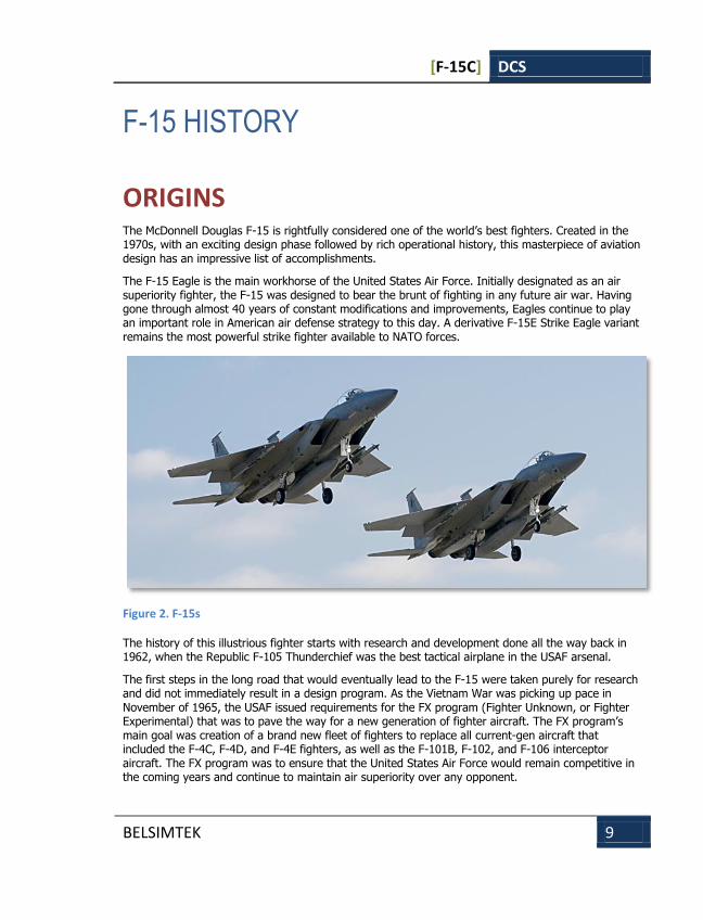
ORIGINS The McDonnell Douglas F-15 is rightfully considered one of the world’s best fighters. Created in the 1970s, with an exciting design phase followed by rich operational history, this masterpiece of aviation design has an impressive list of accomplishments.
The F-15 Eagle is the main workhorse of the United States Air Force. Initially designated as an air superiority fighter, the F-15 was designed to bear the brunt of fighting in any future air war. Having gone through almost 40 years of constant modifications and improvements, Eagles continue to play an important role in American air defense strategy to this day. A derivative F-15E Strike Eagle variant remains the most powerful strike fighter available to NATO forces.
Figure 2. F-15s
The history of this illustrious fighter starts with research and development done all the way back in 1962, when the Republic F-105 Thunderchief was the best tactical airplane in the USAF arsenal.
The first steps in the long road that would eventually lead to the F-15 were taken purely for research and did not immediately result in a design program. As the Vietnam War was picking up pace in November of 1965, the USAF issued requirements for the FX program (Fighter Unknown, or Fighter Experimental) that was to pave the way for a new generation of fighter aircraft. The FX program’s main goal was creation of a brand new fleet of fighters to replace all current-gen aircraft that included the F-4C, F-4D, and F-4E fighters, as well as the F-101B, F-102, and F-106 interceptor aircraft. The FX program was to ensure that the United States Air Force would remain competitive in the coming years and continue to maintain air superiority over any opponent.

[F-15C] DCS
BELSIMTEK 10
Figure 3: F-4E
Preliminary specifications for the FX program were finalized by December of 1965. By March of next year, three aerospace manufacturers, Boeing, Lockheed Martin, and North American, were all awarded contracts to begin work on their competing designs. According to specifications, the fighter had to have a top speed of Mach 3.0, carry a single pilot, and field a range of medium and long-range weapons including guided missiles. These specifications were largely formed in response to the new Soviet MiG-25 Foxbat fighter.
The specifications paid little heed to the new fighter’s dogfighting capabilities. The new aircraft was generally envisioned to follow in the F-111’s footsteps as a universal air defense interceptor.
However, the Vietnam War quickly exposed a fatal flaw in this approach. As it turned out, close-range dogfights were still very much a part of air combat. Even the best air-to-air missile of the day, the AIM-7 Sparrow, was responsible for no more than 20% of total kills, while the majority were claimed with short-range AIM-9 Sidewinders and guns. These statistics led to a drastic revision of the FX specifications in 1967. The USAF now wanted a highly maneuverable fighter that could best a MiG-21 Fishbed in a knife fight while still being superior at medium and beyond visual range combat.
A 1967 Soviet air power demonstration at Domodedovo airfield also contributed to the change. New Soviet developments proudly displayed in the skies over Moscow let the US and NATO know that the Russians were very still very much in the game.
[F-15C] DCS
BELSIMTEK 11
The US Congress subsequently launched closed hearings to investigate issues with combat aviation, including the ability of the US Air Force to effectively combat new Soviet aircraft that including the Tu-128 Fiddler interceptor, Su-15 Flagon interceptor, MiG-23 Flogger, MiG-25 Foxbat, Tu-22K Blinder supersonic bomber, and the Su-17 Fitter attack aircraft. Experts considered these planes to be the most capable designs available to the Soviet bloc. The hearings added more urgency to the FX program. A next generation fighter capable of holding back the Soviet threat had to enter production as soon as possible. Once again, the US had to mobilize its enormous intellectual and manufacturing resources to answer an emerging threat.
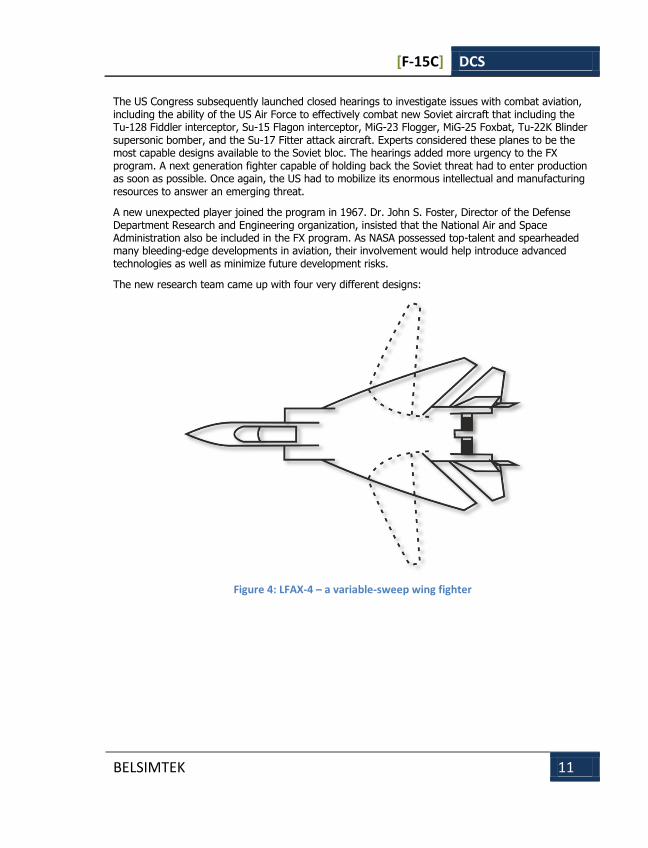
A new unexpected player joined the program in 1967. Dr. John S. Foster, Director of the Defense Department Research and Engineering organization, insisted that the National Air and Space Administration also be included in the FX program. As NASA possessed top-talent and spearheaded many bleeding-edge developments in aviation, their involvement would help introduce advanced technologies as well as minimize future development risks.
The new research team came up with four very different designs:
Figure 4: LFAX-4 – a variable-sweep wing fighter
[F-15C] DCS
BELSIMTEK 12
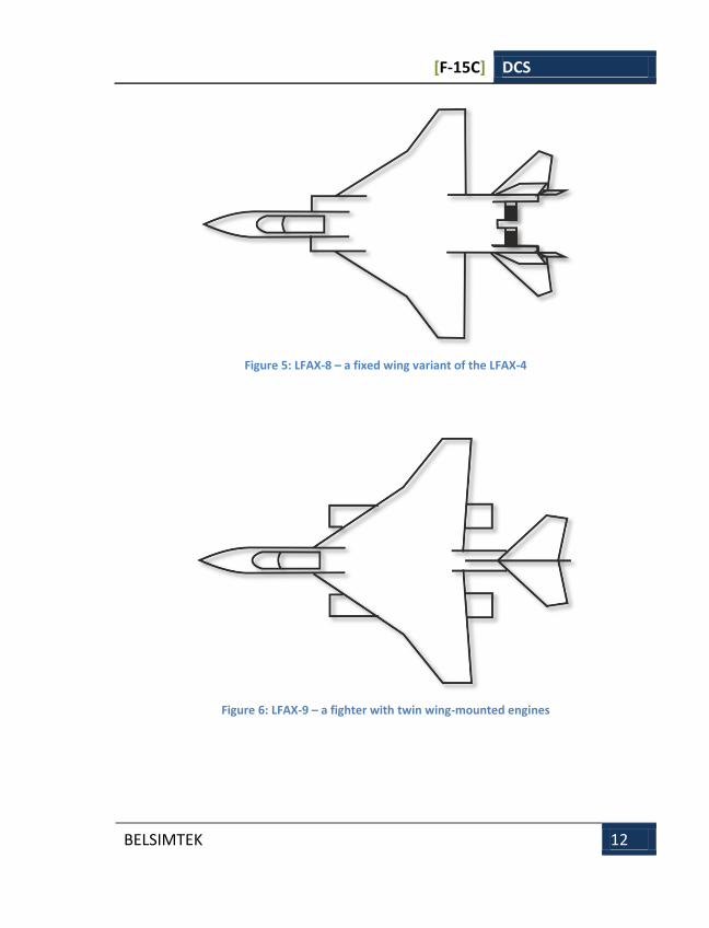
Figure 5: LFAX-8 – a fixed wing variant of the LFAX-4
Figure 6: LFAX-9 – a fighter with twin wing-mounted engines
[F-15C] DCS
BELSIMTEK 13
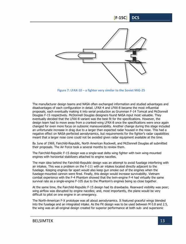
Figure 7: LFAX-10 – a fighter very similar to the Soviet MiG-25
The manufacturer design teams and NASA often exchanged information and studied advantages and disadvantages of each configuration in detail. LFAX-4 and LFAX-8 became the most influential proposals, each eventually making it into serial production as Grumman F-14 Tomcat and McDonnell Douglas F-15 respectively. McDonnell Douglas designers found NASA input most valuable. They eventually decided that the LFAX-8 variant was the best fit for the specifications. However, the design team had to move away from a cranked-wing LFAX-8 once the specifications were once again changed for even more focus on subsonic maneuverability. Another change during this stage included an unfortunate increase in drag due to a larger than expected radar housed in the nose. This had a negative effect on NASA-perfected aerodynamics, but requirements for the fighter’s radar capabilities meant that a larger nose cone could not be avoided given radar equipment available at the time.
By June of 1969, Fairchild-Republic, North American Rockwell, and McDonnell Douglas all submitted their proposals. The Air Force took a several months to review them.
The Fairchild-Republic F-15 design was a single-seat delta wing fighter with twin wing-mounted engines with horizontal stabilizers attached to engine nacelles.
The main idea behind the Fairchild-Republic design was an attempt to avoid fuselage interfering with air intakes. This was a problem on the F-111 with air intakes located directly adjacent to the fuselage. Keeping engines far apart would also keep gun smoke out of the engines when the fuselage-mounted cannon were fired. Finally, this design would increase survivability. Vietnam combat experience with the F-4 Phantom showed that the twin-engine F-4 had virtually the same survival rate as a single-engine F-105 due to the Phantom’s engines being so close together.
At the same time, the Fairchild-Republic F-15 design had its drawbacks. Rearward visibility was poor; wing airflow was disrupted by engine nacelles; and, most importantly, the plane would be very difficult to pilot on one engine in an emergency.
The North-American F-X prototype was all about aerodynamics. It featured graceful wings blended into the fuselage and an integrated intake. As the FX design was to be used between M 0.8 and 2.5, the wing was an all-original design created for superior performance at both sub- and supersonic
[F-15C] DCS
BELSIMTEK 14
speeds. The air intake integrated into the fuselage was yet another unique feature based on mounds of data North American Aviation gathered during the XB-70 Valkyrie bomber project.
Aerodynamically, all prototypes were a huge leap forward compared to current-gen fighters.
The winning design was announced on December 23, 1969. The McDonnell Douglas F-15 would become NATO’s fourth generation air superiority fighter. The decision was based on the design’s individual merits as well as its manufacturer’s extensive experience mass-producing jet fighters for USAF and USN. The aircraft was officially named the F-15 Eagle.
The contract for a whopping (at the time) $1.16 billion called for the initial delivery of 20 single-seat fighters and 2 two-seater TF-15 trainers. The design team was led by George Graff. The design team used computers on a wide scale. This enabled the designers to complete the design phase quicker than ever before for an aircraft of comparable complexity. At the same time, a conservative approach to most design decisions was shared by both the manufacturer and Air Force brass to minimize potential problems.
Over 500 design proposals were studied throughout the project. Over 23,000 wind tunnel hours were logged, four times as much as when developing the F-4 Phantom. A scale model was extensively flight-tested in both free and controlled flight. A B-52 mother-plane would take the scale model to altitude and then release it. Lots of aerodynamic data was gathered, especially on stalls and spins.
The F-15 became the first aircraft in US arsenal that could withstand up to 9 Gs. Its speed performance was comparable to that of the Soviet MiG-25. The F-15 was initially required to fly at Mach 3 for extended periods; however, that requirement was eventually toned down when it was realized that extreme speeds were driving manufacturing costs sky-high.
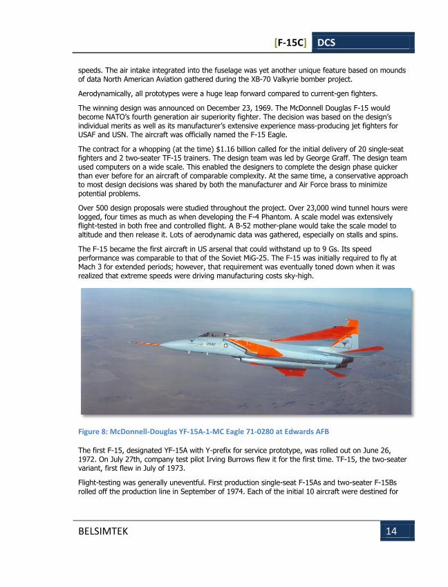
Figure 8: McDonnell-Douglas YF-15A-1-MC Eagle 71-0280 at Edwards AFB
The first F-15, designated YF-15A with Y-prefix for service prototype, was rolled out on June 26, 1972. On July 27th, company test pilot Irving Burrows flew it for the first time. TF-15, the two-seater variant, first flew in July of 1973.
Flight-testing was generally uneventful. First production single-seat F-15As and two-seater F-15Bs rolled off the production line in September of 1974. Each of the initial 10 aircraft were destined for
[F-15C] DCS
BELSIMTEK 15
specific tasks in the flight test program, ranging from engine and avionic tests to armament and tactical evaluation.
The general delivery timeline almost exactly matched the Soviet deliveries of the new MiG-23ML Flogger fighter. Each new F-15 carried a price tag of $12.5 million, making it one of the most expensive fighters to date.
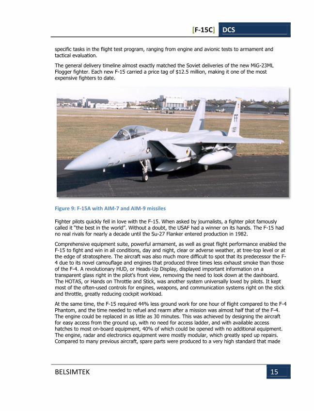
Figure 9: F-15A with AIM-7 and AIM-9 missiles
Fighter pilots quickly fell in love with the F-15. When asked by journalists, a fighter pilot famously called it “the best in the world”. Without a doubt, the USAF had a winner on its hands. The F-15 had no real rivals for nearly a decade until the Su-27 Flanker entered production in 1982.
Comprehensive equipment suite, powerful armament, as well as great flight performance enabled the F-15 to fight and win in all conditions, day and night, clear or adverse weather, at tree-top level or at the edge of stratosphere. The aircraft was also much more difficult to spot that its predecessor the F-4 due to its novel camouflage and engines that produced three times less exhaust smoke than those of the F-4. A revolutionary HUD, or Heads-Up Display, displayed important information on a transparent glass right in the pilot’s front view, removing the need to look down at the dashboard. The HOTAS, or Hands on Throttle and Stick, was another system universally loved by pilots. It kept most of the often-used controls for engines, weapons, and communication systems right on the stick and throttle, greatly reducing cockpit workload.
At the same time, the F-15 required 44% less ground work for one hour of flight compared to the F-4 Phantom, and the time needed to refuel and rearm after a mission was almost half that of the F-4. The engine could be replaced in as little as 30 minutes. This was achieved by designing the aircraft for easy access from the ground up, with no need for access ladder, and with available access hatches to most on-board equipment, 40% of which could be opened with no additional equipment. The engine, radar and electronics equipment were mostly modular, which greatly sped up repairs. Compared to many previous aircraft, spare parts were produced to a very high standard that made
[F-15C] DCS
BELSIMTEK 16
refitting a cinch. Finally, an Auxiliary Power Unit (APU) could be used to autonomously start the engines and avionics, which once again greatly lessened ground crew workload.
FURTHER DEVELOPMENTS McDonnell Douglas and the Air Force began to work on improving the F-15 almost as soon as the first F-15As rolled off the production line. The improved F-15C with its two-seater F-15D variant were to be armed with improved weapons, most importantly the brand new AIM-120 AMRAAM beyond-visual-range air-to-air fire-and-forget missile with active guidance. The operational range for the new missile was a very impressive 30-40 nm.
The F-15C/D entered production in 1978. It had improved radar, air intake and other airframe elements were strengthened, and a greatly increased maximum take-off weight allowed it to carry nearly 2,000 lbs more fuel. Conversely, the AIM-120 program suffered lengthy delays, and the F-15C/D did not receive the new missiles for over a decade. Until then, the AIM-7M Sparrow semi-active radar homing air-to-air missile would have to do.
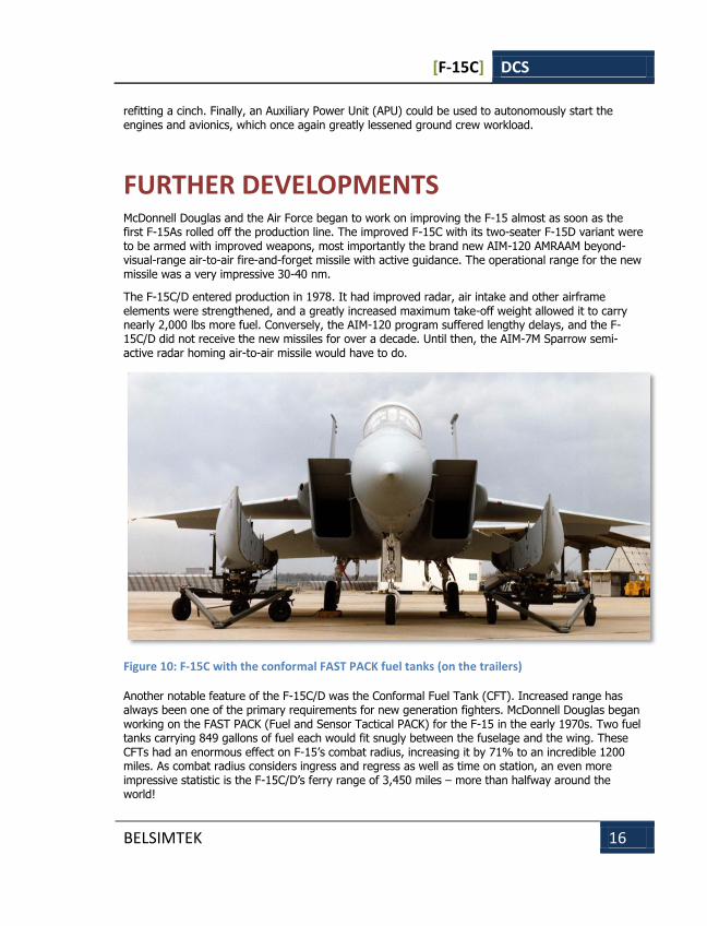
Figure 10: F-15C with the conformal FAST PACK fuel tanks (on the trailers)
Another notable feature of the F-15C/D was the Conformal Fuel Tank (CFT). Increased range has always been one of the primary requirements for new generation fighters. McDonnell Douglas began working on the FAST PACK (Fuel and Sensor Tactical PACK) for the F-15 in the early 1970s. Two fuel tanks carrying 849 gallons of fuel each would fit snugly between the fuselage and the wing. These CFTs had an enormous effect on F-15’s combat radius, increasing it by 71% to an incredible 1200 miles. As combat radius considers ingress and regress as well as time on station, an even more impressive statistic is the F-15C/D’s ferry range of 3,450 miles – more than halfway around the world!
[F-15C] DCS
BELSIMTEK 17
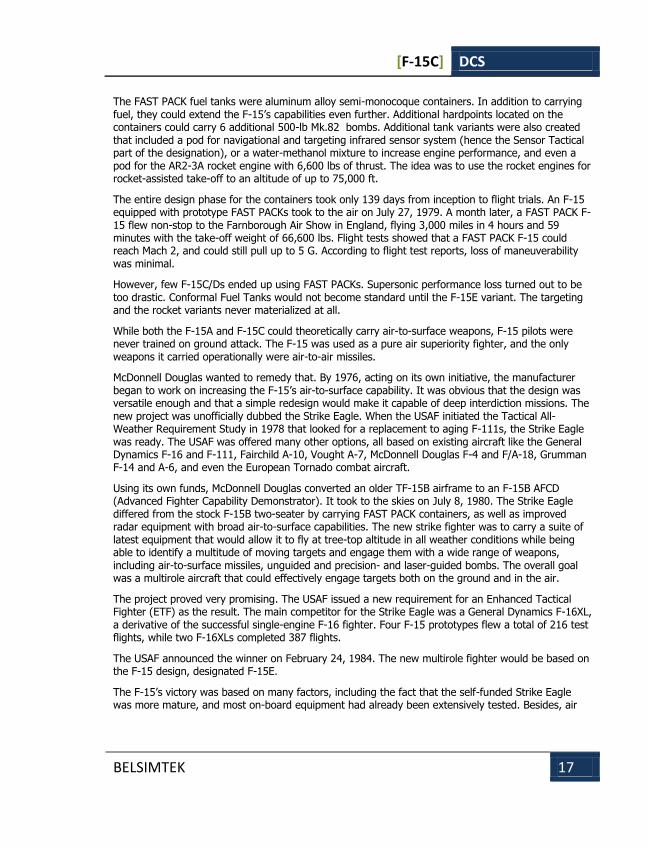
The FAST PACK fuel tanks were aluminum alloy semi-monocoque containers. In addition to carrying fuel, they could extend the F-15’s capabilities even further. Additional hardpoints located on the containers could carry 6 additional 500-lb Mk.82 bombs. Additional tank variants were also created that included a pod for navigational and targeting infrared sensor system (hence the Sensor Tactical part of the designation), or a water-methanol mixture to increase engine performance, and even a pod for the AR2-3A rocket engine with 6,600 lbs of thrust. The idea was to use the rocket engines for rocket-assisted take-off to an altitude of up to 75,000 ft.
The entire design phase for the containers took only 139 days from inception to flight trials. An F-15 equipped with prototype FAST PACKs took to the air on July 27, 1979. A month later, a FAST PACK F-15 flew non-stop to the Farnborough Air Show in England, flying 3,000 miles in 4 hours and 59 minutes with the take-off weight of 66,600 lbs. Flight tests showed that a FAST PACK F-15 could reach Mach 2, and could still pull up to 5 G. According to flight test reports, loss of maneuverability was minimal.
However, few F-15C/Ds ended up using FAST PACKs. Supersonic performance loss turned out to be too drastic. Conformal Fuel Tanks would not become standard until the F-15E variant. The targeting and the rocket variants never materialized at all.
While both the F-15A and F-15C could theoretically carry air-to-surface weapons, F-15 pilots were never trained on ground attack. The F-15 was used as a pure air superiority fighter, and the only weapons it carried operationally were air-to-air missiles.
McDonnell Douglas wanted to remedy that. By 1976, acting on its own initiative, the manufacturer began to work on increasing the F-15’s air-to-surface capability. It was obvious that the design was versatile enough and that a simple redesign would make it capable of deep interdiction missions. The new project was unofficially dubbed the Strike Eagle. When the USAF initiated the Tactical All-Weather Requirement Study in 1978 that looked for a replacement to aging F-111s, the Strike Eagle was ready. The USAF was offered many other options, all based on existing aircraft like the General Dynamics F-16 and F-111, Fairchild A-10, Vought A-7, McDonnell Douglas F-4 and F/A-18, Grumman F-14 and A-6, and even the European Tornado combat aircraft.
Using its own funds, McDonnell Douglas converted an older TF-15B airframe to an F-15B AFCD (Advanced Fighter Capability Demonstrator). It took to the skies on July 8, 1980. The Strike Eagle differed from the stock F-15B two-seater by carrying FAST PACK containers, as well as improved radar equipment with broad air-to-surface capabilities. The new strike fighter was to carry a suite of latest equipment that would allow it to fly at tree-top altitude in all weather conditions while being able to identify a multitude of moving targets and engage them with a wide range of weapons, including air-to-surface missiles, unguided and precision- and laser-guided bombs. The overall goal was a multirole aircraft that could effectively engage targets both on the ground and in the air.
The project proved very promising. The USAF issued a new requirement for an Enhanced Tactical Fighter (ETF) as the result. The main competitor for the Strike Eagle was a General Dynamics F-16XL, a derivative of the successful single-engine F-16 fighter. Four F-15 prototypes flew a total of 216 test flights, while two F-16XLs completed 387 flights.
The USAF announced the winner on February 24, 1984. The new multirole fighter would be based on the F-15 design, designated F-15E.
The F-15’s victory was based on many factors, including the fact that the self-funded Strike Eagle was more mature, and most on-board equipment had already been extensively tested. Besides, air
[F-15C] DCS
BELSIMTEK 18
force brass was skeptical about a single-seat multirole fighter while a two-seater F-16 would require a lot more time and money to develop.
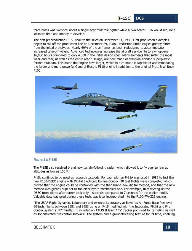
The first preproduction F-15E took to the skies on December 11, 1986. First production examples began to roll off the production line on December 29, 1988. Production Strike Eagles greatly differ from the initial prototypes. Nearly 60% of the airframe has been redesigned to accommodate increased take-off weight. Advanced technologies increase the aircraft service life to a whopping 16,000 hours compared to only 4,000 in the initial design spec. Many elements that suffer the most wear-and-tear, as well as the entire rear fuselage, are now made of diffusion-bonded superplastic-formed titanium. This made the engine bays larger, which in turn made it capable of accommodating the larger and more powerful General Electric F110 engine in addition to the original Pratt & Whitney F100.
Figure 11: F-15E
The F-15E also received brand new terrain-following radar, which allowed it to fly over terrain at altitudes as low as 100 ft.
F-15s continue to be used as research testbeds. For example: an F-15A was used in 1982 to test the new F100-DEEC engine with Digital Electronic Engine Control. 30 test flights were completed which proved that the engine could be controlled with the then brand-new digital method, and that the new method was greatly superior to the older hydro-mechanical one. For example, fully revving up the DEEC from idle to afterburner took only 4 seconds, compared to 7 seconds for the earlier model. Valuable data gathered during these tests was later incorporated into the F100-PW-229 engine.
The USAF Flight Dynamics Laboratory and Avionics Laboratory at Edwards Air Force Base flew over 60 tests flights between 1981 and 1983 using an F-15 modified with the Integrated Flight and Fire Control system (IFFC Firefly). It included an ATLIS II laser / TV tracker pod used for targeting as well as sophisticated fire control software. The system had a groundbreaking feature for its time, enabling
[F-15C] DCS
BELSIMTEK 19
the fighter equipped with it to attack both ground and air targets at the same while flying at any imaginable angle of attack. Flight tests showed than an F-15 so equipped could attack its targets and egress in one third of the time of a stock F-15. Sophisticated sensors and smart weapons meant that targets could be attacked from stand-off range.
By June 1983 yet another F-15 testbed was flying at Edwards. This time, a new FCS digital Flight Control System was being tested. Compared to older analogue systems, the new semi-fly-by-wire system assisted with controlling the aircraft and linked flight controls to engine and fire control as well as navigation systems. The overall effect was very positive. The new FCS greatly improved F-15’s capabilities without costly airframe or engine modifications.
At the same time, USAF issued a new requirement for an F-15 variant with shorter take-off capabilities. An experimental F-15STOL (Short Take-Off and Landing) variant that had been in the works for some time was then flown in response to the new requirements. The aircraft had some novel features, including thrust vectoring, jet nozzles, and canard foreplanes derived from F/A-18 stabilators. The 20-degree two-dimensional thrust vectoring nozzles developed by Pratt & Whitney required a significant redesign to the fighter’s cooling system. The fighter also received a brand new flight control system that managed traditional control surfaces as well as canard foreplanes, the engine, jet nozzles, nose wheel, and main wheel brakes, all at the same time. The key feature of the new control system was its adaptability. It was designed to keep the aircraft flyable in the event of individual system failure, redistributing control input to available devices to keep the aircraft stable if at all possible. Landing gear was also strengthened to accommodate increased vertical speed on landing. Coupled with low-pressure pneumatics the improved landing gear allowed the new F-15 to operate from wet, bomb-damaged, and even unpaved runways. The aircraft also received a new landing autopilot that could land it in poor weather or low visibility conditions. Improved AN/APG-70 radar offered greatly improved resolution of 8.5 ft for ranges up to 13 miles, and 17 ft for up to 24 miles. All these changes had a negative effect as well. Additional equipment greatly increased the aircraft’s weight. The new radar alone weighed 2,400 lbs more than the older variant.
The STOL testbed, later designated STOL/MTD (Short Takeoff and Landing/Maneuver Technology Demonstrator), was loaned to NASA for additional research. It was used in the ACTIVE (Advanced Control Technology for Integrated Vehicles) program where Boeing and Pratt & Whitney also collaborated. The program lasted from 1993 to 1999.
Comment [W1]: Need check dates and features
[F-15C] DCS
BELSIMTEK 20
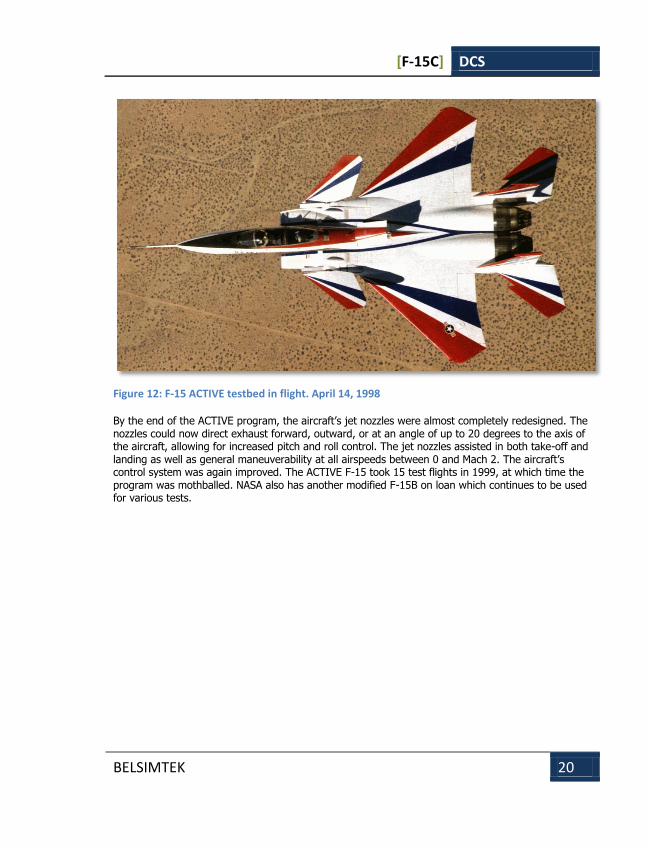
Figure 12: F-15 ACTIVE testbed in flight. April 14, 1998
By the end of the ACTIVE program, the aircraft’s jet nozzles were almost completely redesigned. The nozzles could now direct exhaust forward, outward, or at an angle of up to 20 degrees to the axis of the aircraft, allowing for increased pitch and roll control. The jet nozzles assisted in both take-off and landing as well as general maneuverability at all airspeeds between 0 and Mach 2. The aircraft’s control system was again improved. The ACTIVE F-15 took 15 test flights in 1999, at which time the program was mothballed. NASA also has another modified F-15B on loan which continues to be used for various tests.
[F-15C] DCS
BELSIMTEK 21
MULTISTAGE IMPROVEMENT PROGRAM
Several issues were identified as brand new F-15A and B models entered service. For instance, air intakes proved to be structurally weak and stricter G limits had to be imposed. The air intakes had to be redesigned in order to allow the F-15 to perform to spec. This would also mean retrofitting existing airframes. This was the first step in the F-15 Multistage Improvement Program (MSIP) that has continued ever since. USAF awarded a $155 million to McDonnell Douglas in 1984 that, in part, included airframe improvements that increased G limits for production F-15A/B/C/D from 7 to 9 Gs, as well as strengthening the landing gear and increasing maximum take-off weight by almost 13,000 lbs. The plane would also receive a new on-board computer, new fire control system with color MFDs, and an improved ECM suite that included automatic countermeasures against selected threats. A new MSIP F-15C prototype first took to the skies on June 20, 1985.
Another important stage of the MSIP in the late 1990s equipped F-15C/D with new multifunction display and connected it to the Link 16 military tactical data exchange network. The system linked the F-15 with the Joint Tactical Information Distribution System (JTIDS) that gave it greatly improved access to data from airborne early warning, ground-based radar and forward air defenses, and other tactical aircraft. The program included plans to upgrade all frontline USAF F-15s as well as 100 National Guard F-15s.
The 9/11 attacks spurred a rapid expansion of the MSIP program that also included F-15Es. Older CRT MFDs were replaced with new LCD displays. The most importance change however was the replacement of the aging AN/APG-63 radar with an Active Electronically Scanned Array system designated AN/APG-63(V)2. 18 F-15Cs based at Elmendorf Air Force Base in Alaska were the first to receive the new radar.
By 2006 there were 396 F-15C/D fighters flying with the USAF, as well as 126 F-15A/B/C/Ds with Air National Guard units. The USAF also had 217 multirole F-15Es. These were slated to be replaced with new F-22A Raptors starting in 2005. However, the scope of the F-22A program was eventually reduced from 648 planned in the late 1990s. This meant that up to 250 F-15C/Ds would stay in service with the USAF until 2020, and up to 200 F-15Es would remain in service for an even longer, undetermined period. As the result, the Multistage Improvement Program began yet another phase.
The new phase includes many improvements to both the F-15C/D and F-15E. It included updates to avionics, as well as the new Joint Helmet Mounted Cueing System (JHMCS). Some F-15C/D fighters also received the new and improved radar system first tried out on export F-15K destined for South Korea. Improvements to the F-15’s airframe include replacement honeycomb wing tips to newer components less susceptible to water corrosion.
The program also aims to unify F-15C/D and F-15E on-board computers into one standard unit. The aircraft will also receive an improved ILS system, as well as engine improvements. Finally, F-15C/Ds will be equipped with the latest AIM-9X Sidewinder short-range air-to-air missile.
Other countries also made their own modifications to the F-15. On July 28, 2003 Japanese Mitsubishi Heavy Industries (MHI) started flight-testing a modified F-15J fighter. The first modification stage included installation of a new Raytheon radar as well as a new Lockheed Martin central processing unit. The second improvement stage equipped the aircraft with a new Japanese-built radar unit. The improvement program called for 12 improved F-15J to be delivered to the Japanese Air Force by late 2005.
Comment [MW2]: Removed language about a new engine monitoring display, it is not true.
Comment [AC3]: MiG-31 has a passive ESA not AESA.
[F-15C] DCS
BELSIMTEK 22
In conclusion, the Multistage Improvement Program has been very successful in keeping the nearly 40-year-old design competitive throughout its service history. It is clear that F-15s will remain in frontline service well into the 21st century. Considering the current and planned improvement stages, we can rest assured that F-15 Eagles will continue pushing the envelope for fighter aviation for years to come.
F-15s ENTER SERVICE Despite some design flaws in early production F-15A/Bs, these aircraft were the best tactical aircraft in the USAF arsenal of the early 1980s. USAF units based in Western Europe showed the highest operational readiness levels. In March of 1982, operational readiness for all USAF F-15s was 64.5 %, while the aircraft stationed in Europe were rated at 73.1%. The 36th Tactical Wing based at Bitburg AFB in Germany showed the lowest levels at 71.4 % while being reequipped with the latest F-15C and F-15D models. However, as the aircrews became used to the new airframes, the operational readiness level at Bitburg rose to an astonishing 92.8%.
The 36th TFW fielded 79 F- 15 aircraft In the early 1980s. Three fighter squadrons fielded 72 fighters, and 7 more aircraft were in reserve, intended to replace combat losses or as temporary replacements during maintenance. Bitburg AFB played a key role in NATO air defense strategy throughout the Cold War. Four 36th Wing aircraft were kept in a constant state of readiness, ready to scramble in under five minutes. Eagle pilots constantly trained for rapid take-off and interception, often showing results under 4 minutes, with the absolute record scramble of 3 minutes and 37 seconds. Air crews practiced constantly, with a monthly average of 50-60 practice scrambles.
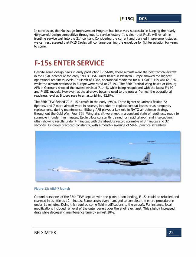
Figure 13: AIM-7 launch
Ground personnel of the 36th TFW kept up with the pilots. Upon landing, F-15s could be refueled and rearmed in as little as 12 minutes. Some crews even managed to complete the entire procedure in under 11 minutes. Doing this required some field modifications to the aircraft. For instance, local modifications included removal of the outer panels over the engine exhaust. This slightly increased drag while decreasing maintenance time by almost 10%.
[F-15C] DCS
BELSIMTEK 23
The Eagles also demonstrated their outstanding capabilities on the other side of the world. In the course of the Team Spirit 82 exercise held in the western Pacific, 24 F-15A fighters based at Kadena Air Base (Okinawa) completed 418 simulated combat sorties in 9 days, 233 of them in only 3 days. Combat readiness levels for Asian-based F-15s was almost 100%.
The F-15 also set new records in flight safety. By April 1982, Eagles had accumulated over 523,000 flight hours with the average accident rate second only to A- 10A (the USAF considers any event to be a flight accident where the aircraft damage amounts to at least $0.5 million). By 1984, the accident rate for the F- 15 fleet has decreased even further, becoming the lowest in the U.S. Air Force. It remains such to this day, with the average of 2.4 accidents per 100,000 flying hours.
High reliability and survivability of the aircraft are best illustrated with specific examples. An F-15 collided with another aircraft during simulated aerial combat. The collision sheared off the left side of the left stabilizer and rudder, as well as most of the left vertical stabilizer. However, the plane managed to fly back to base and land safely. Another simulated dogfight against an A-4 Skyhawk also ended in a collision. As a result, an Israeli F-15 almost completely lost its right wing, leaving only a 2-ft section of the wing root. Nevertheless, the F-15 pilot still found that the aircraft was controllable and decided to land. He landed at an airspeed of 330 mph, nearly twice the normal landing speed, and used the landing hook for additional braking. McDonnell Douglas experts reviewed the incident in detail and found that the F-15 could produce sufficient lift for controlled flight with just the fuselage and one wing.
In a yet another incident, an F-15 fuselage drop tank was struck by lightning, which ignited the fumes. Over 200 pieces of resulting shrapnel struck the lower part of the fuselage and the aircraft was severely damaged by fire. Nevertheless, this aircraft also managed to safely land.
As of late 1999, F-15s of the U.S. Air Force as well as those serving with Israel, Saudi Arabia and Japan flew a total of more than 3.5 million hours, proving extremely reliable and showing some of the best combat readiness levels in the history of aviation.
F-15s IN COMBAT The first country to use the F-15 in combat was Israel during a complex multi-faction civil war started in Lebanon in 1975. Syrian influence on the conflict was strong from day one and continued to grow. By 1976 the Arab League voted to introduce 40,000 peacekeeping troops to Lebanon, most of them from the Syrian armed forces. Israel briefly invaded Southern Lebanon in 1978 and later withdrew to maintain a 12-mile safety corridor along the southern border. This set the stage for a face-off between Israeli and Syrian air forces.
Israeli F-15s first entered combat on June 27, 1979. Israeli strike fighters, escorted by a flight of F-15s, were en route to Palestinian positions in southern Lebanon when two flights of Syrian MiG-21bis Fishbeds were scrambled to intercept. The Fishbed was the most modern fighter then available to the Syrians. The Israeli escorts, six F-15s and a pair of IAI Kfir fighters, moved to engage. The Israeli fighters were directed by a Northrop Grumman E-2C Hawkeye tactical airborne early warning aircraft on station over the Mediterranean. A close-quarters maneuvering dogfight ensued, and in the end, four MiG-21s were claimed by the F-15s, and one more was shared by an F-15 and a Kfir. Four of the five kill claims were eventually confirmed. Another MiG was damaged, but the pilot managed to make it to the Rayak Air Base in Libya. Israel claimed that no losses were suffered on their side.
[F-15C] DCS
BELSIMTEK 24
The next aerial battle took place on September 19th. Israeli F-15 pilots claimed four more Fishbeds. A large dogfight took place on September 24th where F-15s played a large role once again and led to four more kill claims by the Israeli Air Force.
F-15As claimed another MiG on August 24, 1980. Another air battle on December 31 of 1980 had conflicting claims; the Israelis claimed two MiGs for no losses, while the Syrians claimed that they only lost one Fishbed and destroyed one Israeli fighter.
In general, air battles over Lebanon showed that the Israeli Air Force equipped with fourth-generation fighters and early warning aircraft had a significant advantage over the Syrians.
The most notable action in which Israeli F-15s took part was Operation Opera, also known as Operation Babylon, a surprise attack on an Iraqi nuclear reactor on July 7, 1981. The strike itself was conducted by eight F-16As, while six F-15As flew top cover. The strike group took off from Etzion Air Base in the Sinai Peninsula. The F-16s bypassed Jordanian air defenses from the South, then ingressed via Saudi desert and entered Iraqi air space. The F-15s never crossed into Iraq. F-16s dropped sixteen Mark 84 2,000-lb bombs, at least eight of which struck the Osirak reactor complex.
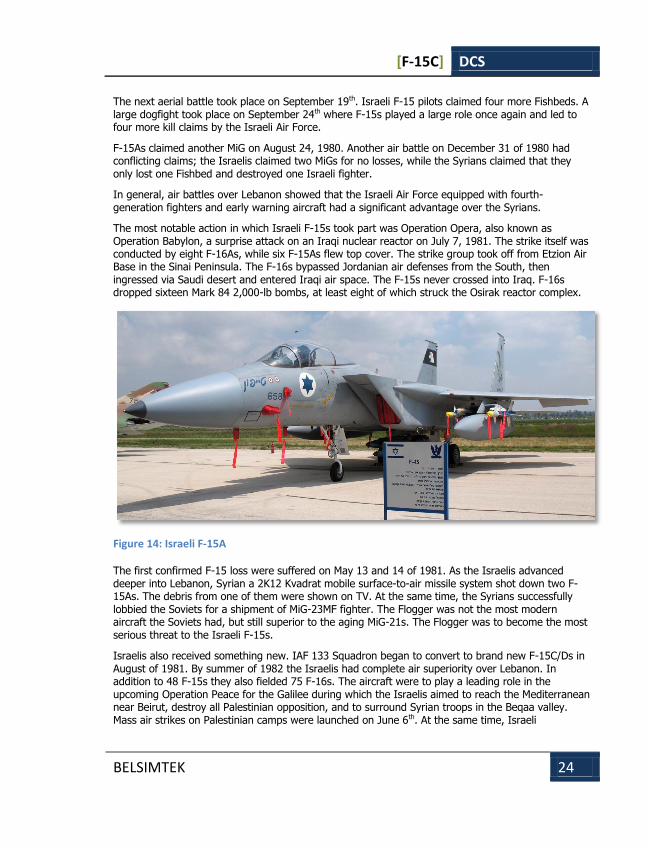
Figure 14: Israeli F-15A
The first confirmed F-15 loss were suffered on May 13 and 14 of 1981. As the Israelis advanced deeper into Lebanon, Syrian a 2K12 Kvadrat mobile surface-to-air missile system shot down two F-15As. The debris from one of them were shown on TV. At the same time, the Syrians successfully lobbied the Soviets for a shipment of MiG-23MF fighter. The Flogger was not the most modern aircraft the Soviets had, but still superior to the aging MiG-21s. The Flogger was to become the most serious threat to the Israeli F-15s.
Israelis also received something new. IAF 133 Squadron began to convert to brand new F-15C/Ds in August of 1981. By summer of 1982 the Israelis had complete air superiority over Lebanon. In addition to 48 F-15s they also fielded 75 F-16s. The aircraft were to play a leading role in the upcoming Operation Peace for the Galilee during which the Israelis aimed to reach the Mediterranean near Beirut, destroy all Palestinian opposition, and to surround Syrian troops in the Beqaa valley. Mass air strikes on Palestinian camps were launched on June 6th. At the same time, Israeli
[F-15C] DCS
BELSIMTEK 25
mechanized divisions attacked on a wide front on the ground. The Syrians soon moved their tank divisions towards the front line and engaged the Israelis. Early in the morning, as the battle was just starting, two Syrian MiG-23MFs intercepted an Israeli BQM-34 unmanned aerial vehicle and destroyed it with an R-23 air-to-air missile launched from a distance of 11 km (6.8 miles). The returning Syrian fighters were then intercepted by Israeli F-15As guided by an E-2C Hawkeye. The Syrians managed to escape unscathed, defeating all Israeli missiles, then setting their variable-geometry wings to maximum angle, increased airspeed and extended away and out of reach.
The next day saw Israeli aircraft strike Syrian forces in the Beqaa valley. The standard attack profile would first have an E-2C Hawkeye take position over the neutral waters off the Lebanon coast. The Hawkeye would both watch for incoming threats as well as engage in electronic warfare. The Hawkeye would usually be covered by two or four F-15s staying outside Syrian radar range. Another group of two to four flights of F-15s and F-16s would then go on station on the approaches to Beirut, ready to attack any emerging threat. A strike group of F-4 Phantoms would arrive last. Israeli aircraft would approach Lebanon at an altitude of about 6,000 ft, staying off Syrian radar until going feet dry, where they would be detected by ground observes anyway. At the same time, Israeli Hawkeyes could monitor any Syrian aircraft that broke 300 feet of altitude.
The Israelis had another tactical surprise for the enemy over Lebanon. Instead of using heavier longer-range F-15s, they would engage enemy aircraft with lighter F-16As that only carried medium to short-range weapons. F-16s would approach at low altitude in trail formation, then use the lead pair to break away and try to sandwich Syrian fighters. If the F-16 trap did not work, F-15s would enter the battle at a significant tactical advantage.
Main groups of Israeli and Syrian forces engaged each other on June 9th by the El Zahrani river. Air combat reached its peak intensity. Syrians claimed that two MiG-23MFs attacked a pair of F-16s in the morning and shot down one, then lost one of the MiGs to the remaining Falcon. In another area, the Syrians claim that another pair of MiGs managed to shoot down an F-15, also losing one MiG-23 to an F-15 air-to-air missile. This has never confirmed. 14 hours of non-stop battles brought more kills. By late evening, pilots of the 133 Squadron shot down two more MiG-23MFs and two MiG-23MSs. One of the surviving Syrian pilots later said that the destruction of his aircraft came as a complete surprise. In addition to six newer MiG-23 Floggers the Israelis also claimed six aging MiG-21 Fishbeds that day to no confirmed F-15 losses.
The Syrians claimed to have shot down six Israeli aircraft on that day, including two F-15s. However these claims are not supported by Israeli Air Force or any other verifiable source.
The next day, June 10th, saw the most heated aerial battle with up to 350 aircraft in the air from both sides. The Israelis claimed a total of 26 kills, including seven scored by F-15s. Syrians had confirmed losing 22 aircraft. On June 11th Syrians admitted losing two MiG-23s and four MiG-21s to F-15s.
[F-15C] DCS
BELSIMTEK 26
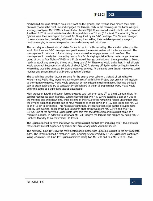
Figure 15: Syrian MiG-23ML
In total, Israeli fighter pilots claimed 47 Arab fighters between June 6 and 11, including four MiG-23MS, six MiG-23MF, twenty-six MiG-21bis and eleven MiG-21MF. Most of the kills were claimed by F-15As and F-15Cs. At the same time, low-altitude F-16 and F-15 fighters in conjunction with ground-based air defenses claimed seven Su-22M and fourteen MiG-23BN fighter-bombers as well as three helicopters. Data on Israeli Air Force losses is fuzzy. Syrians claimed 42 Israeli aircraft shot down, including at least five F-15s, as well as 1 or 2 unmanned aerial vehicles. Israelis claim that not a single F-15 was lost and no contradictory evidence has indicated otherwise.
The main weapon used by the IAF in June of 1982 was the Python 3 short-range air-to-air missile. AIM-7F Sparrow medium-range semi-active radar homing air-to-air missile was slightly less effective. Several enemy aircraft were shot down with guns.
Due in large part to the action over Lebanon, the Israeli Air Force accounts for over half of all F-15 kills ever scored.
The F-15C also played an important role in the 1991 Gulf War. 120 US and Saudi fighters flew over 5,900 sorties during Desert Storm, claiming 37 out of 39 total air kills. US F-15s claimed 35 of those kills, that included Mirage F1, MiG-23, MiG-25, Su-22 and Su-25 aircraft; two more Mirage F1 were shot down by a Saudi pilot in a single engagement. All kills were scored with AIM-7s or AIM-9s, and all took place during intercepts guided by airborne early warning aircraft.
F-15Cs were also the most powerful fighter used during the Balkans conflict of 1999. They performed various missions including strategic bomber escort as well as various air-to-air missions. The first F-15 kill of the conflict was claimed by F-15Cs of the 48th Fighter Wing guided by an E-3 Sentry to a flight of Serbian fighters that entered Bosnian airspace. US fighters reported shooting down two MiG-29s, one of which crashed on Bosnian territory, with the pilot successfully ejecting to evade capture. Serbians, in turn, falsely claimed to have shot down two F-15s without losses.
[F-15C] DCS
BELSIMTEK 27
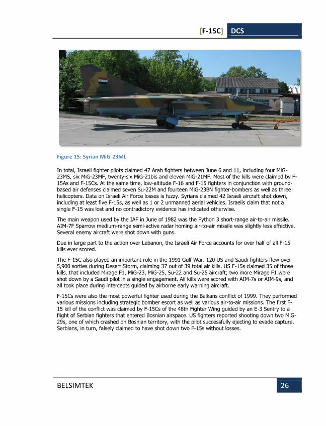
Figure 16: A Kuwaiti A-4KU Skyhawk and a U.S. Air Force F-15C Eagle stand on an airfield prior to a mission during Operation Desert Storm on 2 February 1991
Total results for NATO F-15s used in operation Allied Force is four MiG-29s shot down for no losses, all claimed with AIM-120 missiles.
USAF and Air National Guard F-15s began to actively patrol US airspace after the 9/11 terror attacks.
F-15Cs were also widely used in subsequent combat operations in the Persian Gulf. During the 2003 operation Iraqi Freedom, Iraq air-to-air combat was very limited. The Iraqi Air Force refused to take to the air, with the entire air force mounting a single sortie by a recon MiG-25RB. F-15s could score no kills under such circumstances. However, they routinely patrolled Iraqi airspace in conjunction with airborne early warning aircraft. While Iraqi air defenses remained active, F-15s were one of few aircraft types to suffer no losses to enemy fire.
The USAF is currently in the process of replacing F-15s with new F-22A Raptor fighters. Many revolutionary design elements of the new fighter make it a worthy successor to the venerable F-15.
[F-15C] DCS
BELSIMTEK 28
GAME AVIONICS MODE
GAME AVIONICS MODE
[F-15C] DCS
BELSIMTEK 29
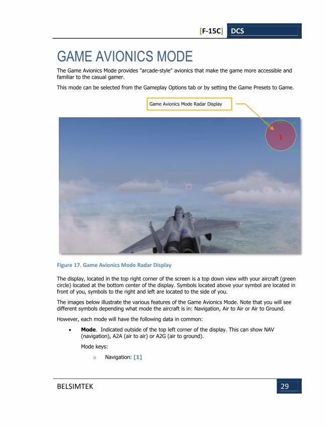
GAME AVIONICS MODE The Game Avionics Mode provides "arcade-style" avionics that make the game more accessible and familiar to the casual gamer.
This mode can be selected from the Gameplay Options tab or by setting the Game Presets to Game.
Figure 17. Game Avionics Mode Radar Display
The display, located in the top right corner of the screen is a top down view with your aircraft (green circle) located at the bottom center of the display. Symbols located above your symbol are located in front of you, symbols to the right and left are located to the side of you.
The images below illustrate the various features of the Game Avionics Mode. Note that you will see different symbols depending what mode the aircraft is in: Navigation, Air to Air or Air to Ground.
However, each mode will have the following data in common:
Mode. Indicated outside of the top left corner of the display. This can show NAV (navigation), A2A (air to air) or A2G (air to ground).
Mode keys:
o Navigation: [1]
Game Avionics Mode Radar Display
[F-15C] DCS
BELSIMTEK 30
o Air to Air: [2], [4] or [6]
o Air to Ground: [7]
Radar Range. Outside the top right of the display is the current range setting of the easy radar.
Radar range keys:
o Zoom in: [=]
o Zoom out: [-]
True Airspeed (TAS). Outside the lower left of the display is the true airspeed of your aircraft.
Radar Altitude. Outside the lower right of the display is the radar altimeter that indicates your altitude above the ground or water.
Current Heading. Inside the display at the center top is your current aircraft magnetic heading.
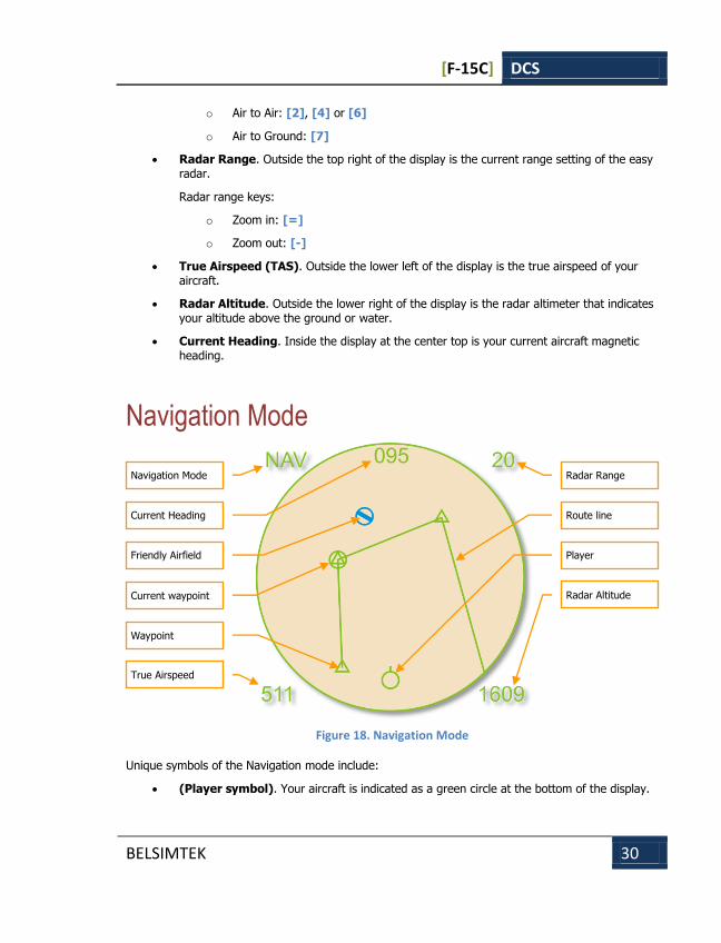
Navigation Mode
Figure 18. Navigation Mode
Unique symbols of the Navigation mode include: (Player symbol). Your aircraft is indicated as a green circle at the bottom of the display.
Navigation Mode
Current Heading
Friendly Airfield
Current waypoint
Waypoint
True Airspeed
Radar Range
Route line
Player
Radar Altitude

[F-15C] DCS
BELSIMTEK 31
(Friendly Airfield symbol). This blue symbol indicates friendly airfields.
(Current waypoint symbol). This green circle indicates your current waypoint. You can cycle your waypoint with the [LCtrl - ~] (tilde) key.
(Waypoint symbol). This green triangle indicates other waypoints in your flight plan.
(Route line). Green route lines connect the waypoints in your flight plan.
Air to Air Mode
Figure 19. Air to Air Mode
Unique symbols of the Air to Air mode include:
(Player symbol). Your aircraft is indicated as a green circle at the bottom of the display.
(Friendly aircraft). All friendly aircraft are indicated as blue circles with lines coming from them that indicate flight direction.
(Enemy aircraft). All enemy aircraft are indicated as red circles with lines coming from them that indicate flight direction.
(Friendly missile). A friendly missile is indicated as a blue dot.
(Enemy missile). An enemy missile is indicated as a red dot.
Useful key commands when in Air to Air mode include:
Air to Air Mode
Current Heading
Friendly missile
Friendly aircraft
True Airspeed
Radar Range
Enemy aircraft
Player
Radar Altitude
Enemy missile

[F-15C] DCS
BELSIMTEK 32
Auto Lock Center Aircraft: [RAlt - F6]
Auto Lock Nearest Aircraft: [RAlt - F5]
Auto Lock On Next Aircraft: [RAlt - F7]
Auto Lock Previous Aircraft: [RAlt - F8]
[F-15C] DCS
BELSIMTEK 33
COCKPIT INSTRUMENTS
COCKPIT INSTRUMENTS

[F-15C] DCS
BELSIMTEK 34
F-15C COCKPIT INSTRUMENTS The F-15С is an air superiority fighter. That’s why its cockpit instruments are focused around the radar indicator and TEWS display, which are positioned a little lower than the HUD. The lower section of the instrument panel consists of instruments for engine control, navigation, weapon availability, fuel amount and countermeasures.
Figure 20. F-15C Instrument Panel
1. Multi-Purpose Color Display (MPCD)
2. IAS and Mach meter
1 2 3 4 5 6 7 8 9 10
12 13 14 15 16 17 18 19 20 21
11

[F-15C] DCS
BELSIMTEK 35
3. Vertical Situation Display (VSD)
4. Attitude Director Indicator (ADI)
5. Vertical Velocity Indicator (VVI)
6. Altimeter
7. Fan turbine inlet temperature indicators (FTIT)
8. Engine tachometers
9. TEWS display unit
10. Fuel quantity indicator
11. Chaff, flare lights
12. Landing gear control handle
13. Landing gear position indicator
14. Angle of attack indicator
15. Accelerometer
16. Horizontal Situation Indicator (HSI)
17. Clock
18. Engine fuel flow indicators
19. Engine exhaust nozzle position indicator
20. Cabin pressure altimeter
21. Caution lights panel
Vertical Situation Display (VSD) The Vertical Situation Display (VSD), which is also called the "radar scope", takes up the upper left corner of the instrument panel. The VSD shows the air situation in front of the aircraft, detailing information on other aircraft detected by the radar. Detailed information regarding radar use is dealt with in the corresponding chapter.
[F-15C] DCS
BELSIMTEK 36
Figure 21. VSD
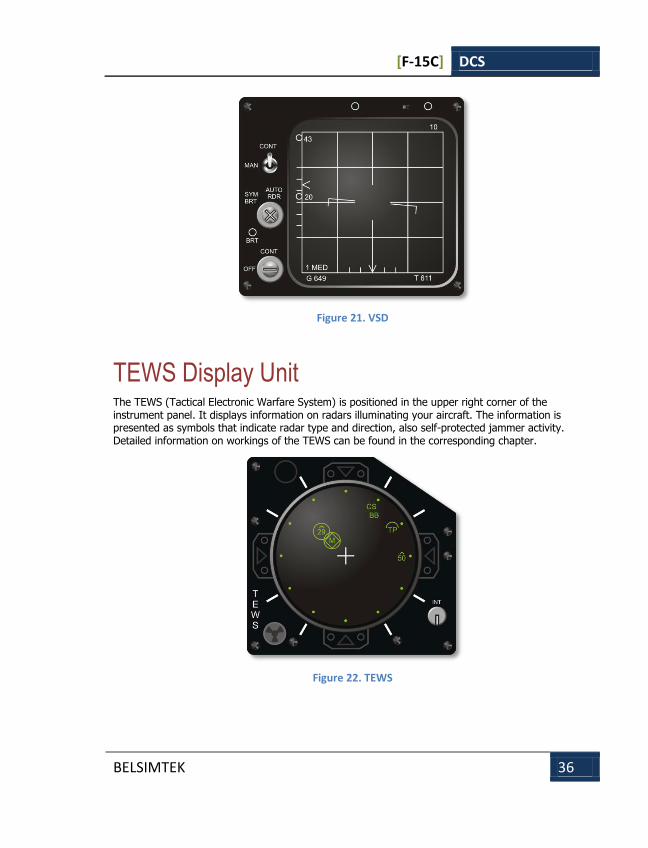
TEWS Display Unit The TEWS (Tactical Electronic Warfare System) is positioned in the upper right corner of the instrument panel. It displays information on radars illuminating your aircraft. The information is presented as symbols that indicate radar type and direction, also self-protected jammer activity. Detailed information on workings of the TEWS can be found in the corresponding chapter.
Figure 22. TEWS
[F-15C] DCS
BELSIMTEK 37
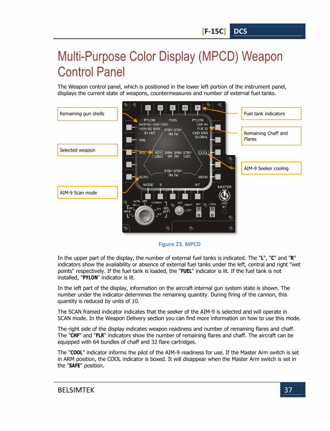
Multi-Purpose Color Display (MPCD) Weapon Control Panel The Weapon control panel, which is positioned in the lower left portion of the instrument panel, displays the current state of weapons, countermeasures and number of external fuel tanks.
Figure 23. MPCD
In the upper part of the display, the number of external fuel tanks is indicated. The "L", "C" and "R" indicators show the availability or absence of external fuel tanks under the left, central and right "wet points" respectively. If the fuel tank is loaded, the "FUEL" indicator is lit. If the fuel tank is not installed, "PYLON" indicator is lit.
In the left part of the display, information on the aircraft internal gun system state is shown. The number under the indicator determines the remaining quantity. During firing of the cannon, this quantity is reduced by units of 10.
The SCAN framed indicator indicates that the seeker of the AIM-9 is selected and will operate in SCAN mode. In the Weapon Delivery section you can find more information on how to use this mode.
The right side of the display indicates weapon readiness and number of remaining flares and chaff. The "CHF" and "FLR" indicators show the number of remaining flares and chaff. The aircraft can be equipped with 64 bundles of chaff and 32 flare cartridges.
The "COOL" indicator informs the pilot of the AIM-9 readiness for use. If the Master Arm switch is set in ARM position, the COOL indicator is boxed. It will disappear when the Master Arm switch is set in the "SAFE" position.
Remaining gun shells
Selected weapon
AIM-9 Scan mode
Fuel tank indicators
Remaining Chaff and
Flares
AIM-9 Seeker cooling
[F-15C] DCS
BELSIMTEK 38
In the central part of the display, information on the types of loaded missiles and their readiness state is shown. The aircraft has eight external weapon stations – four of them are under the fuselage and two are on each wing pylon. "Air-to-air" missiles are subdivided into two categories. Different variants of the AIM-9 are indicated by the SRM (Short Range Missiles) indicator; variants of AIM-7 and AIM-120 are indicated by the MRM (Medium Range Missiles) indicator. The type and state of each missile is shown on the corresponding pylon.
If you choose the MRM type, the weapon station of the chosen missile will appear as "RDY"; all other missiles of that type will be indicated as "STBY".
If you choose the SRM type, the station of the selected missile will appear as "RDY"; all other missiles of that type will be indicated as "STBY".
Figure 1 shows the different missiles that the F-15C can use.
Designation Misisle type Class
7M AIM-7M MRM
120B AIM-120B MRM
120C AIM-120C MRM
9M AIM-9M SRM
9P AIM-9P SRM
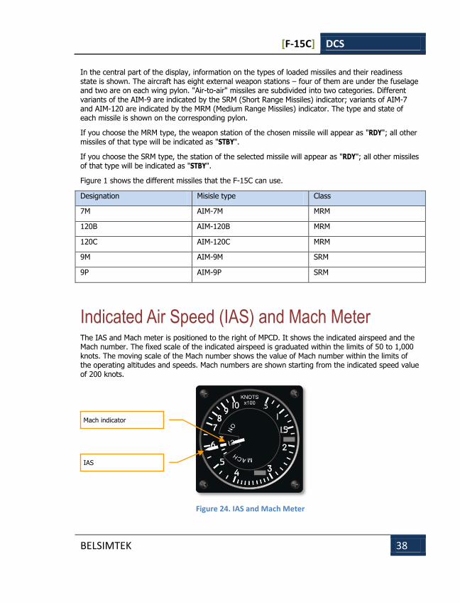
Indicated Air Speed (IAS) and Mach Meter The IAS and Mach meter is positioned to the right of MPCD. It shows the indicated airspeed and the Mach number. The fixed scale of the indicated airspeed is graduated within the limits of 50 to 1,000 knots. The moving scale of the Mach number shows the value of Mach number within the limits of the operating altitudes and speeds. Mach numbers are shown starting from the indicated speed value of 200 knots.
Figure 24. IAS and Mach Meter
Mach indicator
IAS

[F-15C] DCS
BELSIMTEK 39
Angle-of-Attack (AoA) Indicator The AoA indicator is positioned on the instrument panel under the IAS and Mach meter. It is used for indicating the current AoA value within the limits of 0 to 45 units. The AoA indicated values do not correspond to actual degrees. In the area of the landing AoA (20-22 units) there is a corresponding index on the indicator.
Figure 25. Angle-of-Attack Indicator
Accelerometer The Accelerometer shows the current values of positive and negative G loads. G marks show the maximum allowable values of positive and negative loads. These instrument readings are independent and are not as accurate as the readings indicated on the HUD.
Figure 26. Accelerometer
Current G-load
Maximum negative G Marker
Maximum positive G Marker
[F-15C] DCS
BELSIMTEK 40
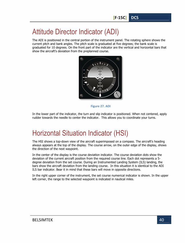
Attitude Director Indicator (ADI) The ADI is positioned in the central portion of the instrument panel. The rotating sphere shows the current pitch and bank angles. The pitch scale is graduated at five degrees; the bank scale is graduated for 10 degrees. On the front part of the indicator are the vertical and horizontal bars that show the aircraft’s deviation from the preplanned course.
Figure 27. ADI
In the lower part of the indicator, the turn and slip indicator is positioned. When not centered, apply rudder towards the needle to center the indicator. This allows you to coordinate your turns.
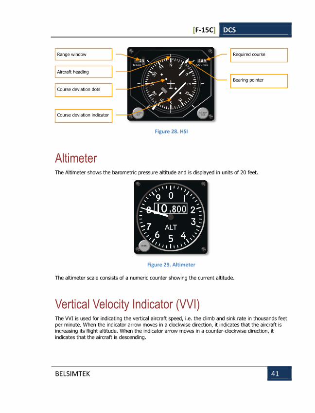
Horizontal Situation Indicator (HSI) The HSI shows a top-down view of the aircraft superimposed on a compass. The aircraft’s heading always appears at the top of the display. The course arrow, on the outer edge of the display, shows the direction of the next waypoint.
In the center of the display is the course deviation indicator. The course deviation dots show the deviation of the current aircraft position from the required course line. Each dot represents a 5-degree deviation from the set course. During an Instrumented Landing System (ILS) landing, the bars show the aircraft deviation from the landing course. In this situation it is identical to the ADI ILS bar indicator. Bear it in mind that these bars will move in opposite directions.
In the right upper corner of the instrument, the set course numerical indicator is shown. In the upper left corner, the range to the selected waypoint is indicated in nautical miles.
[F-15C] DCS
BELSIMTEK 41
Figure 28. HSI
Altimeter The Altimeter shows the barometric pressure altitude and is displayed in units of 20 feet.
Figure 29. Altimeter
The altimeter scale consists of a numeric counter showing the current altitude.
Vertical Velocity Indicator (VVI) The VVI is used for indicating the vertical aircraft speed, i.e. the climb and sink rate in thousands feet per minute. When the indicator arrow moves in a clockwise direction, it indicates that the aircraft is increasing its flight altitude. When the indicator arrow moves in a counter-clockwise direction, it indicates that the aircraft is descending.
Range window
Aircraft heading
Course deviation dots
Course deviation indicator
Required course
Bearing pointer

[F-15C] DCS
BELSIMTEK 42
Figure 30. Vertical Velocity Indicator
Tachometer This pair of tachometers indicate engine RPM. They shown percentages of the maximum RPM, and the red zone corresponds to the "afterburner" zones.
Figure 31. Tachometer
Fan Turbine Inlet Temperature Indicators The two Fan Turbine Inlet Temperature Indicators are positioned below the tachometer. The indicator scale is graduated for each 100 degrees Celsius. The indicator arrow in the red zone shows dangerously high turbine gas temperature.
[F-15C] DCS
BELSIMTEK 43
Figure 32. Fan Turbine Inlet Temperature Indicators (FTIT)
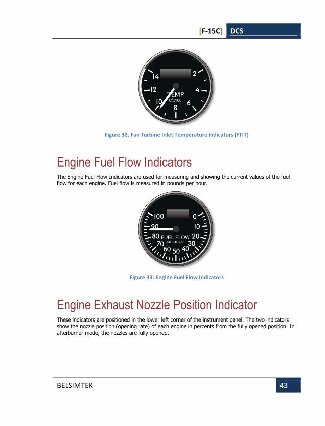
Engine Fuel Flow Indicators The Engine Fuel Flow Indicators are used for measuring and showing the current values of the fuel flow for each engine. Fuel flow is measured in pounds per hour.
Figure 33. Engine Fuel Flow Indicators
Engine Exhaust Nozzle Position Indicator These indicators are positioned in the lower left corner of the instrument panel. The two indicators show the nozzle position (opening rate) of each engine in percents from the fully opened position. In afterburner mode, the nozzles are fully opened.
[F-15C] DCS
BELSIMTEK 44
Figure 34. Engine Exhaust Nozzle Position Indicator
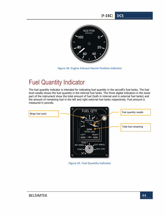
Fuel Quantity Indicator The fuel quantity indicator is intended for indicating fuel quantity in the aircraft’s fuel tanks. The fuel level needle shows the fuel quantity in the internal fuel tanks. The three digital indicators in the lower part of the instrument show the total amount of fuel (both in internal and in external fuel tanks) and the amount of remaining fuel in the left and right external fuel tanks respectively. Fuel amount is measured in pounds.
Figure 35. Fuel Quantity Indicator
Bingo fuel caret Fuel quantity needle
Total fuel remaining
[F-15C] DCS
BELSIMTEK 45
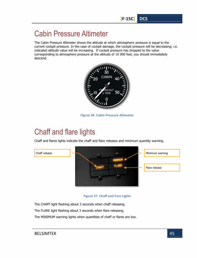
Cabin Pressure Altimeter The Cabin Pressure Altimeter shows the altitude at which atmospheric pressure is equal to the current cockpit pressure. In the case of cockpit damage, the cockpit pressure will be decreasing; i.e. indicated altitude value will be increasing. If cockpit pressure has dropped to the value corresponding to atmosphere pressure at the altitude of 10 000 feet, you should immediately descend.
Figure 36. Cabin Pressure Altimeter
Chaff and flare lights Chaff and flares lights indicate the chaff and flare releases and minimum quantity warning.
Figure 37. Chaff and Fare Lights
The CHAFF light flashing about 3 seconds when chaff releasing.
The FLARE light flashing about 3 seconds when flare releasing.
The MINIMUM warning lights when quantities of chaff or flares are low.
Chaff release Minimum warning
Flare release

[F-15C] DCS
BELSIMTEK 46
F-15C HUD Operating Modes
Basic F-15C HUD Symbols There is a set of HUD symbols that remain unchanged in HUD operating modes.
Figure 38. Basic F-15C HUD symbols
In the center of the HUD is a fixed aircraft datum "W", which shows the position of the aircraft’s longitudinal axis.
The aircraft’s total velocity vector (aka flight path marker) indicator is positioned in the HUD but can move all around depending on the maneuvering of the aircraft. It indicates the current aircraft flight path.
The current heading scale is positioned in the upper part of the HUD. The inverted caret along the scale indicates the aircraft’s current heading. (For example, 04 corresponds to the value of 40 degrees).
On the airspeed scale, which is positioned along the left side of the HUD, the indicated aircraft airspeed is shown in indicated knots. Speeds less than 150 knots are not indicated. The caret position on the scale indicates the aircraft’s current speed.
On the altitude scale, along the right side of the HUD, absolute (barometrical) altitude is shown in feet. The caret position on the scale indicates the aircraft’s current altitude.
Heading scale
Pitch scale
Aircraft airspeed
Current heading
Gun cross
Aircraft datum
Absolute
(barometric)
altitude
Velocity vector
Current and max
allowed G

[F-15C] DCS
BELSIMTEK 47
The speed scale on the left side of the HUD indicates the Indicted Air Speed (IAS) of the aircraft. The caret along the side denotes your current airspeed in relation to the scale.
The pitch scale is positioned in the central portion of the HUD and is linked with the velocity vector indicator. The scale is graduated for 5 degrees. Depending on the banking direction, the scale moves either to the right or to the left, indicating the aircraft’s banking direction and value. In fact, it backs up the bank indicator on the ADI.
The gun gross is a fixed cross near the top center of the HUD and is aligned with the internal gun.
In the lower left corner of the HUD, the current G loading (two digit value with decimal point assumed between) and the maximum allowed G are indicated.
Navigation Mode In HUD navigation mode, various types of information are shown. In the main navigation mode (NAV), the direction to the selected waypoint is shown on the HUD. In the landing mode, (ILSN), information necessary for landing the aircraft is provided.
Navigation Mode (NAV) In NAV mode, steering directions to the selected waypoint are provided. In addition to the primary set of indicators, additional indicators are shown on the HUD. These include:
Figure 39. HUD Navigation Mode
Bank Steering
index
Assigned heading
Current waypoint
number
Range to the
current waypoint
Flight time to the
next waypoint
[F-15C] DCS
BELSIMTEK 48
The bank steering index is a vertical line that can move left and right across the HUD, and provides you course steering to the selected waypoint. Roll the aircraft to keep the steering index in the center of the HUD to reach the selected waypoint along the course line.
The assigned heading mark on the heading scale provides you direct steering to the selected waypoint when the mark is aligned with the current heading mark in the center of the heading scale.
In the lower right corner of NAV HUD, the current NAV mode and selected waypoint number are displayed. (1 NAV)
Beneath the HUD mode indication, the range to the selected waypoint in nautical miles is shown. (N 42.1)
At the bottom of this data block, the time to reach the selected waypoint (if the current speed is maintained) is shown. (7 MIN)
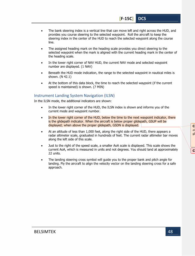
Instrument Landing System Navigation (ILSN) In the ILSN mode, the additional indicators are shown:
In the lower right corner of the HUD, the ILSN index is shown and informs you of the current mode and waypoint number.
In the lower right corner of the HUD, below the time to the next waypoint indicator, there is the glidepath indicator. When the aircraft is below proper glidepath, GSUP will be displayed; when above the proper glidepath, GSDN is displayed.
At an altitude of less than 1,000 feet, along the right side of the HUD, there appears a radar altimeter scale, graduated in hundreds of feet. The current radar altimeter bar moves along the left side of this scale.
Just to the right of the speed scale, a smaller AoA scale is displayed. This scale shows the current AoA, which is measured in units and not degrees. You should land at approximately 22 units.
The landing steering cross symbol will guide you to the proper bank and pitch angle for landing. Fly the aircraft to align the velocity vector on the landing steering cross for a safe approach.
Comment [AC4]: Olgerd says that GSUP – aircraft below glidepath and GSDN - aircraft over
glidepath.
Comment [MW5]: Thanks, corrected.
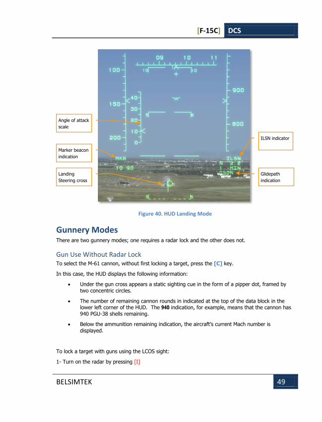
[F-15C] DCS
BELSIMTEK 49
Figure 40. HUD Landing Mode
Gunnery Modes There are two gunnery modes; one requires a radar lock and the other does not.
Gun Use Without Radar Lock To select the M-61 cannon, without first locking a target, press the [C] key.
In this case, the HUD displays the following information:
Under the gun cross appears a static sighting cue in the form of a pipper dot, framed by two concentric circles.
The number of remaining cannon rounds in indicated at the top of the data block in the lower left corner of the HUD. The 940 indication, for example, means that the cannon has 940 PGU-38 shells remaining.
Below the ammunition remaining indication, the aircraft’s current Mach number is displayed.
To lock a target with guns using the LCOS sight:
1- Turn on the radar by pressing [I]
Landing
Steering cross
Angle of attack
scale
ILSN indicator
Glidepath
indication
Marker beacon
indication

[F-15C] DCS
BELSIMTEK 50
2- Enable gun by pressing [C]
3- Fly to place target within the static sighting cue.
Figure 41. Gun selected with no radar lock
Gun Director Sight (GDS) When a target has been locked on by radar and Gun is selected, the HUD will enter GDS mode. The GDS HUD displays the information:
Around a locked radar target, a target designation (TD) box is displayed that denotes the location of the locked target in the HUD field. If the gun pipper is placed over the locked target, the TD box is removed.
Along the right side of the HUD, the target range scale is shown. The scale ranges from zero to 10 nautical miles. The vertically sliding caret shows the current range to target.
The GDS gun pipper shows the point where the shells intersect target trajectory. In order for the shells to hit the target, you should place the pipper over the target.
The inscribed circle in the GDS indicates the range to target. Each scale tick corresponds to 1,000 feet. As range to the target decreases, the range scale unwinds counter-clockwise. There is also the Bullet Time-of-Flight dot that indicates the effective gun firing range.
Ammunition
balance
Mach
Static sighting
cue
LCOS gun
sight selected
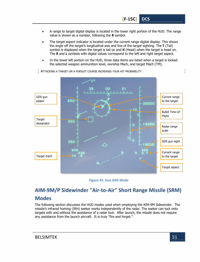
[F-15C] DCS
BELSIMTEK 51
A range to target digital display is located in the lower right portion of the HUD. The range value is shown as a number, following the R symbol.
The target aspect indicator is located under the current range digital display. This shows the angle off the target’s longitudinal axis and line of the target sighting. The T (Tail) symbol is displayed when the target is tail on and H (Head) when the target is head on. The R and L symbols with digital values correspond to the left and right target aspect.
In the lower left portion on the HUD, three data items are listed when a target is locked: the selected weapon ammunition level, ownship Mach, and target Mach (TM).
ATTACKING A TARGET ON A PURSUIT COURSE INCREASES YOUR HIT PROBABILITY
Figure 42. Gun GDS Mode
AIM-9M/P Sidewinder "Air-to-Air" Short Range Missile (SRM)
Modes The following section discusses the HUD modes used when employing the AIM-9M Sidewinder. The missile’s infrared homing (IRH) seeker works independently of the radar. The seeker can lock onto targets with and without the assistance of a radar lock. After launch, the missile does not require any assistance from the launch aircraft. It is truly "fire and forget."
Target
designator
GDS gun
pipper
Bullet Time-of-
Flight
Current range
to the target
Radar range
scale
Current range
to the target
Target aspect
GDS gun sight
Target mach
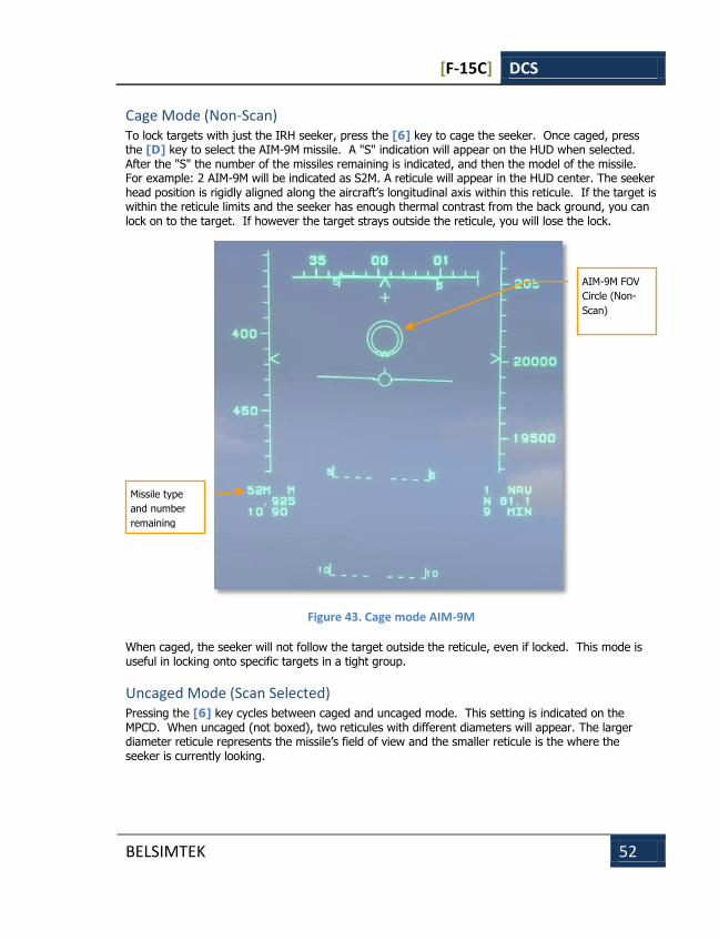
[F-15C] DCS
BELSIMTEK 52
Cage Mode (Non-Scan) To lock targets with just the IRH seeker, press the [6] key to cage the seeker. Once caged, press the [D] key to select the AIM-9М missile. A "S" indication will appear on the HUD when selected. After the "S" the number of the missiles remaining is indicated, and then the model of the missile. For example: 2 AIM-9M will be indicated as S2M. A reticule will appear in the HUD center. The seeker head position is rigidly aligned along the aircraft’s longitudinal axis within this reticule. If the target is within the reticule limits and the seeker has enough thermal contrast from the back ground, you can lock on to the target. If however the target strays outside the reticule, you will lose the lock.
Figure 43. Cage mode AIM-9M
When caged, the seeker will not follow the target outside the reticule, even if locked. This mode is useful in locking onto specific targets in a tight group.
Uncaged Mode (Scan Selected) Pressing the [6] key cycles between caged and uncaged mode. This setting is indicated on the MPCD. When uncaged (not boxed), two reticules with different diameters will appear. The larger diameter reticule represents the missile’s field of view and the smaller reticule is the where the seeker is currently looking.
Missile type
and number
remaining
AIM-9M FOV
Circle (Non-
Scan)

[F-15C] DCS
BELSIMTEK 53
Figure 44. Uncaged Mode (Scan Selected)
The outer reticule size is always fixed. This reticule disappears after the missile seeker locks a target. Once locked, the smaller reticule will frame the target and follow it within its seeker’s gimbal limits across the HUD. When the missile seeker starts to track the target, the pilot hears the high pitched lock tone.
Locking targets through the IRH seeker is a good tactic for stealthy attacks (the emission cannot be picked up by enemy RWS systems). The enemy will be unlikely to detect your attack from the rear hemisphere, and accordingly, will not take defensive measures.
Radar-Slaved Mode In the Vertical Scan [3] or Boresight [4] air combat maneuvering (ACM) modes, the inclusion of radar lock slaving of the IRH seeker provides additional targeting information on the HUD. If the distance to the target is more than 12,000 feet (outside of AIM-9M missile effective range), the following symbols and indications will appear on the HUD:
The ASE Circle shows the maximum steering error angle. The steering error value is proportional to the steering dot deviation from the ASE circle center.
The ASE Circle shows the zone in which the steering dot should be positioned and angular limits to engage a target. The ASE circle increases in size when the distance to the target decreases or the aspect angle increases. This means that as target distance decrease, the missile can be launched with a larger steering error.
AIM-9 seeker
AIM-9M FOV
Circle (Scan
Selected)

[F-15C] DCS
BELSIMTEK 54
The angle off tail line is located on the ASE circle. This shows target aspect angle in relation to your aircraft in a plan view. If it is located at the top of the circle, then the target is moving directly away. If it is located at the bottom of the circle, the target is flying directly towards you.
The target designator (TD box) shows the target position in the space relative to your aircraft.
The target range scale is located along the right portion of the HUD. The range values go from zero to 10 nautical miles. Along this fixed scale, a sliding bar indicates the target’s current range. The number next to the bar shows target closure rate. There are also bars for Rmax and Rmin for an AIM-9 launch. When the current range to target is between the Rmax and Rmin range bars, the target is in the valid launch zone.
Additional data is located in the data block in the lower right portion of the HUD. A digital range value in nautical miles to the target is shown after the "R" symbol. Below the range data is the Time To Intercept (TTI) in seconds that has a preceded S.
THOUGH THE AIM-9 MISSILE IS AN ALL-ASPECT MISSILE, YOU SHOULD ATTACK THE TARGET FROM THE REAR
HEMISPHERE SIDE. THIS WILL INCREASE THE PK
Figure 45. AIM-9 radar slaved
ASE Circle
Steering Dot
Angle off Line
Target Designator
(TD) and seeker
In Range Cue
Current range to
the target
Target Closure
Minimum range
bar
Maximum range
bar
[F-15C] DCS
BELSIMTEK 55
AIM-7M Sparrow "Air-to-Air" Medium Range Missile (MRM)
Modes The AIM-7M missile is one of the two medium-range, air-to-air missile types employed by the F-15C, The missile’s semi-active radar homing (SARH) seeker requires constant target illumination by the radar in STT mode during the missile’s entire time-of-flight.
The following HUD symbology is used with the AIM-7M:
Flood Mode Flood mode is most often used in the close combat arena when a radar lock is unattainable. Flood mode is accessed by pressing the [6] key and is indicated by a large, 12-degree reticule on the HUD. When in this mode, the radar is simply emitting a steady beam of energy that is focused within the FLOOD reticule. By launching an AIM-7M, the missile will attempt to intercept a target within the reticule that is reflecting energy back to the missile’s seeker. The target must be kept within the FLOOD reticule for the entire time of missile flight. As such, you do not have to lock the target with radar before engaging. The "FLOOD" mode indication is displayed on the lower right data block of the HUD. If several targets come into the reticule, the missile will attempt to intercept the target with the largest RCS or closest range. If the target is too far away or leaves the confines of the reticule, the missile will lose tracking and go ballistic.
In the lower left corner of the HUD, the missile type and number remaining is indicated. For the AIM-7M, this is indicated as "M" for the missile type and "M" for the version. For example: four AIM-7M loaded will be indicated as M4M.
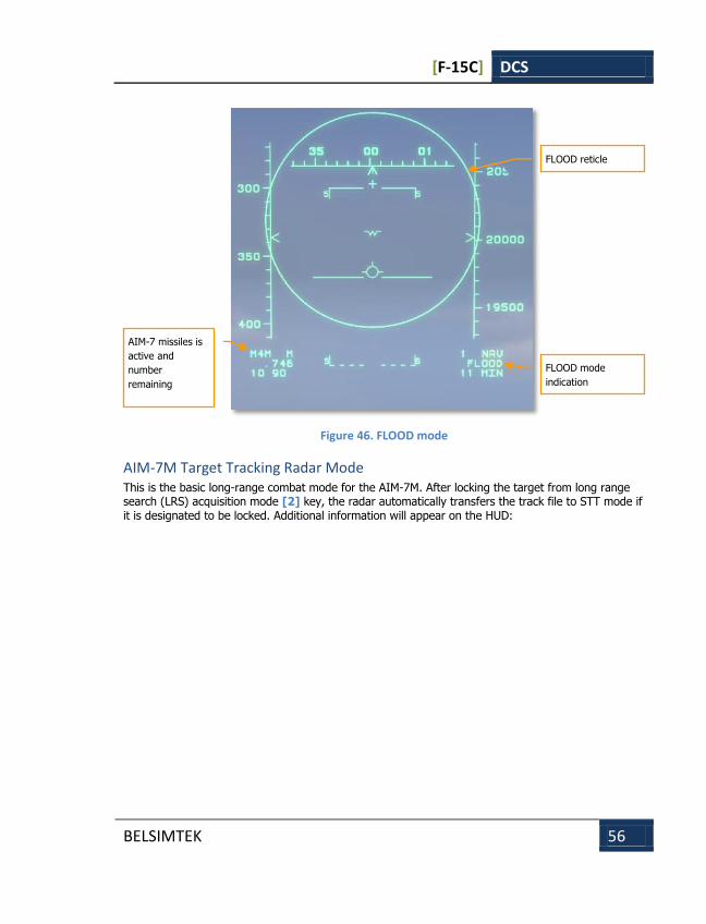
[F-15C] DCS
BELSIMTEK 56
Figure 46. FLOOD mode
AIM-7M Target Tracking Radar Mode This is the basic long-range combat mode for the AIM-7M. After locking the target from long range search (LRS) acquisition mode [2] key, the radar automatically transfers the track file to STT mode if it is designated to be locked. Additional information will appear on the HUD:
AIM-7 missiles is
active and
number
remaining
FLOOD reticle
FLOOD mode
indication

[F-15C] DCS
BELSIMTEK 57
Figure 47. AIM-7M STT mode
The target designation (TD) box shows the position of the target in relation to your aircraft.
The ASE circle shows the maximum, angular steering error probability. The steering error value is proportional to the steering dot from the ASE circle center. The ASE circle shows the zone in which the steering dot should be located prior to launch to hit the target with a given probability kill. The circle increases in size when the distance to the target decreases, which means that as the distance decreases, the missile can be launched with greater steering error. It is necessary, by maneuvering your aircraft, to ensure that the steering dot is located as close to the ASE circle center as possible.
The angle off tail bar is located on the ASE circle. This shows the target aspect angle in relation to your aircraft in a plan view. If it is located at the top of the circle, then the target is heading away. If the bar is located at the bottom of the circle, then the target is heading towards you.
Along the right portion of the HUD, the target range scale is displayed. The scale’s upper limit corresponds to the radar’s current range setting. Three elongated bars on the scale display the missile’s minimal range (Rmin), maximum range to a maneuvering target (Rtr) and maximum range against a non-maneuvering target (Rpi). The sliding bar displays the current range to the designated target. The number next to the range bar displays the combined closure speed.
In the lower right portion of the HUD, the data block provides additional data. This includes current range to target digital display. The range value is shown as a number, following the R symbol.
ASE circle
Steering dot
Angle off line
Target aspect
Target designator
Range scale
RPI
Current range and
closure rate
RTR
Rmin
Valid shot cue
Time to intercept
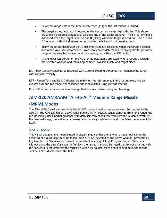
[F-15C] DCS
BELSIMTEK 58
Below the range data is the Time to Intercept (TTI) of the last missile launched.
The target aspect indicator is located under the current range digital display. This shows the angle the target’s longitudinal axis and line of the target sighting. The T (Tail) symbol is displayed when the target is tail on and H (Head) when the target is head on. The "R" and "L" symbols with digital values correspond to the left and right target aspect.
Below the target designator box, a flashing triangle is displayed when the target is locked and within valid shot parameters. Valid shot can be determined by having the target within range of the selected weapon and the steering dot within the ASE circle.
In the lower left portion on the HUD, three data items are listed when a target is locked: the selected weapon and remaining number, ownship Mach, and target Mach.
RPI - Max Range Probability of Intercept with Current Steering. Assumes non-maneuvering target with constant velocity. RTR - Range Turn and Run. Indicates the maximum launch range against a target executing an evasive turn and run maneuver at launch and is calculated using current steering.
Rmin - Rmin is the minimum launch range that assures missile fuzing and tracking.
AIM-120 AMRAAM "Air-to-Air" Medium Range Missile
(MRM) Modes The AIM-120B/C air-to-air missile is the F-15C’s primary medium range weapon. In contrast to the AIM-7M, the AIM-120 has an active radar homing (ARH) seeker. When launched from long range, the missile initially uses inertial guidance with data link corrections received from the launch aircraft. At the terminal stage, the active radar seeker automatically switches on and completes the intercept by itself.
VISUAL Mode This Visual engagement mode is used in visual range combat arena when a radar lock cannot be achieved or a quick shot must be taken. With AIM-120 selected as the active weapon, press the [6] key to enter the Visual mode. Visual permits the launching of AIM-120s, nicknamed Slammers, without using the aircraft’s radar to first lock the target. It should be noted that to lock a target with the seeker, it is required that the target be within 10 nautical miles and it should be in the missile seeker FOV as displayed on the HUD.
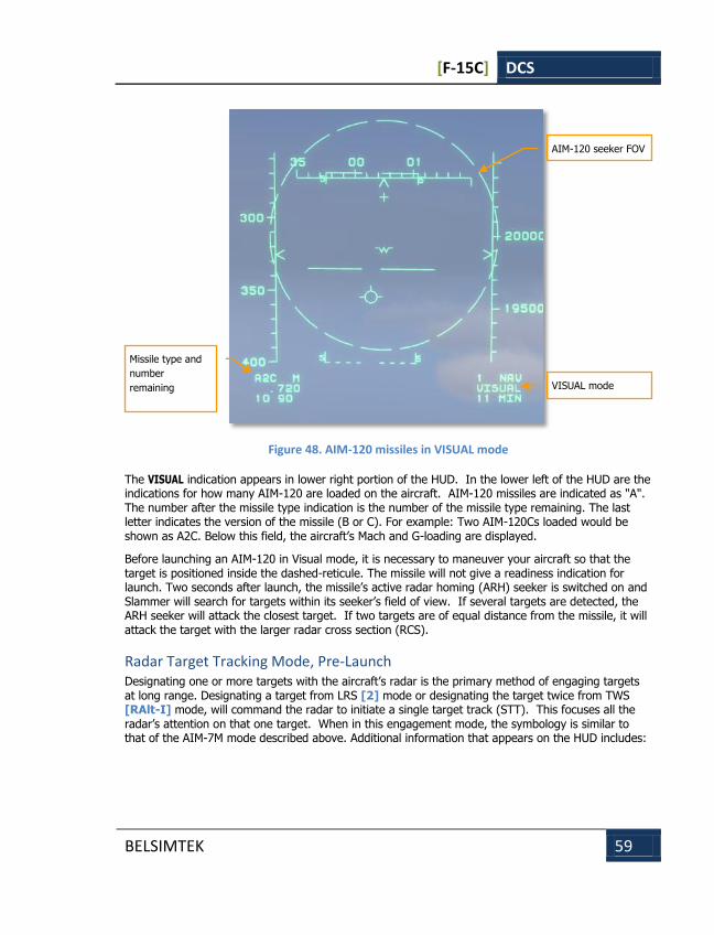
[F-15C] DCS
BELSIMTEK 59
Figure 48. AIM-120 missiles in VISUAL mode
The VISUAL indication appears in lower right portion of the HUD. In the lower left of the HUD are the indications for how many AIM-120 are loaded on the aircraft. AIM-120 missiles are indicated as "A". The number after the missile type indication is the number of the missile type remaining. The last letter indicates the version of the missile (B or C). For example: Two AIM-120Cs loaded would be shown as A2C. Below this field, the aircraft’s Mach and G-loading are displayed.
Before launching an AIM-120 in Visual mode, it is necessary to maneuver your aircraft so that the target is positioned inside the dashed-reticule. The missile will not give a readiness indication for launch. Two seconds after launch, the missile’s active radar homing (ARH) seeker is switched on and Slammer will search for targets within its seeker’s field of view. If several targets are detected, the ARH seeker will attack the closest target. If two targets are of equal distance from the missile, it will attack the target with the larger radar cross section (RCS).
Radar Target Tracking Mode, Pre-Launch Designating one or more targets with the aircraft’s radar is the primary method of engaging targets at long range. Designating a target from LRS [2] mode or designating the target twice from TWS [RAlt-I] mode, will command the radar to initiate a single target track (STT). This focuses all the radar’s attention on that one target. When in this engagement mode, the symbology is similar to that of the AIM-7M mode described above. Additional information that appears on the HUD includes:
Missile type and
number
remaining
AIM-120 seeker FOV
VISUAL mode
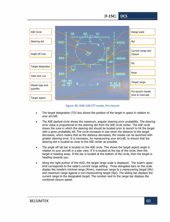
[F-15C] DCS
BELSIMTEK 60
Figure 49. AIM-120 STT mode, Pre-launch
The target designation (TD) box shows the position of the target in space in relation to your aircraft.
The ASE dashed-circle shows the maximum, angular steering error probability. The steering error value is proportional to the steering dot from the ASE circle center. The ASE circle shows the zone in which the steering dot should be located prior to launch to hit the target with a given probability kill. The circle increases in size when the distance to the target decreases, which means that as the distance decreases, the missile can be launched with greater steering error. It is necessary, by maneuvering your aircraft, to ensure that the steering dot is located as close to the ASE center as possible.
The angle off tail bar is located on the ASE circle. This shows the target aspect angle in relation to your aircraft in a plan view. If it is located at the top of the circle, then the target is heading away. If the bar is located at the bottom of the circle, then the target is heading towards you.
Along the right portion of the HUD, the target range scale is displayed. The scale’s upper limit corresponds to the radar’s current range setting. Three elongated bars on the scale display the missile’s minimal range (Rmin), maximum range to a maneuvering target (Rtr) and maximum range against a non-maneuvering target (Rpi). The sliding bar displays the current range to the designated target. The number next to the range bar displays the combined closure speed.
ASE Circle
Steering dot
Angle off Line
Target aspect
Target designator
Range scale
Rpi
Rtr
Rmin
Current range and
closure
Valid shot cue
Missile type and
quantity
Target range
Pre-launch missile
time to intercept
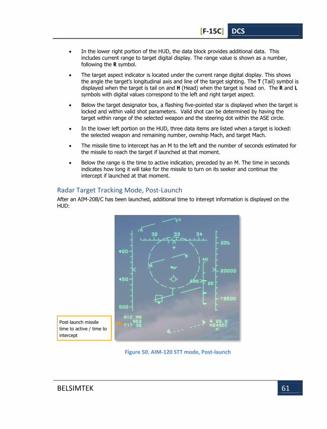
[F-15C] DCS
BELSIMTEK 61
In the lower right portion of the HUD, the data block provides additional data. This includes current range to target digital display. The range value is shown as a number, following the R symbol.
The target aspect indicator is located under the current range digital display. This shows the angle the target’s longitudinal axis and line of the target sighting. The T (Tail) symbol is displayed when the target is tail on and H (Head) when the target is head on. The R and L symbols with digital values correspond to the left and right target aspect.
Below the target designator box, a flashing five-pointed star is displayed when the target is locked and within valid shot parameters. Valid shot can be determined by having the target within range of the selected weapon and the steering dot within the ASE circle.
In the lower left portion on the HUD, three data items are listed when a target is locked: the selected weapon and remaining number, ownship Mach, and target Mach.
The missile time to intercept has an M to the left and the number of seconds estimated for the missile to reach the target if launched at that moment.
Below the range is the time to active indication, preceded by an M. The time in seconds indicates how long it will take for the missile to turn on its seeker and continue the intercept if launched at that moment.
Radar Target Tracking Mode, Post-Launch After an AIM-20B/C has been launched, additional time to interept information is displayed on the HUD:
Figure 50. AIM-120 STT mode, Post-launch
Post-launch missile
time to active / time to
intercept
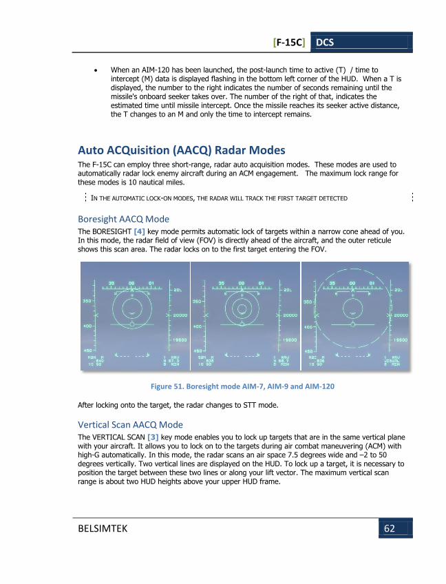
[F-15C] DCS
BELSIMTEK 62
When an AIM-120 has been launched, the post-launch time to active (T) / time to intercept (M) data is displayed flashing in the bottom left corner of the HUD. When a T is displayed, the number to the right indicates the number of seconds remaining until the missile's onboard seeker takes over. The number of the right of that, indicates the estimated time until missile intercept. Once the missile reaches its seeker active distance, the T changes to an M and only the time to intercept remains.
Auto ACQuisition (AACQ) Radar Modes The F-15C can employ three short-range, radar auto acquisition modes. These modes are used to automatically radar lock enemy aircraft during an ACM engagement. The maximum lock range for these modes is 10 nautical miles.
IN THE AUTOMATIC LOCK-ON MODES, THE RADAR WILL TRACK THE FIRST TARGET DETECTED
Boresight AACQ Mode The BORESIGHT [4] key mode permits automatic lock of targets within a narrow cone ahead of you. In this mode, the radar field of view (FOV) is directly ahead of the aircraft, and the outer reticule shows this scan area. The radar locks on to the first target entering the FOV.
Figure 51. Boresight mode AIM-7, AIM-9 and AIM-120
After locking onto the target, the radar changes to STT mode.
Vertical Scan AACQ Mode The VERTICAL SCAN [3] key mode enables you to lock up targets that are in the same vertical plane with your aircraft. It allows you to lock on to the targets during air combat maneuvering (ACM) with high-G automatically. In this mode, the radar scans an air space 7.5 degrees wide and –2 to 50 degrees vertically. Two vertical lines are displayed on the HUD. To lock up a target, it is necessary to position the target between these two lines or along your lift vector. The maximum vertical scan range is about two HUD heights above your upper HUD frame.
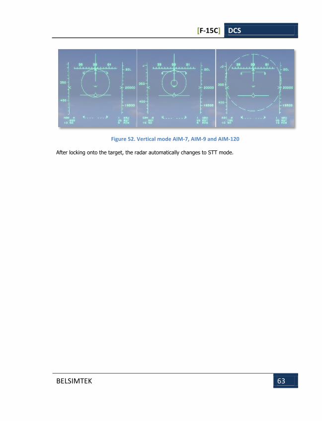
[F-15C] DCS
BELSIMTEK 63
Figure 52. Vertical mode AIM-7, AIM-9 and AIM-120
After locking onto the target, the radar automatically changes to STT mode.

[F-15C] DCS
BELSIMTEK 64
AN/APG-63(V)1 Radar Since the Second World War, the defining feature of an "all-weather fighter" has been its onboard air intercept radar set. By virtue of the ability of radio waves to penetrate clouds, this powerful sensor provides the fighter with the ability to detect and direct weapons against aerial targets day or night, independent of weather conditions that can degrade visual or infrared detection. Radar can also provide a very long detection range, making it the sensor of choice for modern beyond-visual-range (BVR) air combat.
The F-15C fighter has been fitted with several variants of the APG-63 radar during its operational career. The majority of these are "X-band" (10 GHz) radars with mechanically-scanned flat-plate slotted array antennas. The MiG-29 and Su-27 carry the N019 and N001 radars respectively, which operate in the same frequency band but employ twin-reflector "twist-Cassegrain" antennas similar to those of earlier Soviet fighters.
The features and limitations of these air intercept radars largely dictate the tactics employed during the BVR phase of an aerial duel. Although many details remain secret, enough information has become available to create an interesting portrait of the dynamics of BVR combat, in which each adversary seeks to gain advantage by exploiting the hardware limitations of the other.
Radar operates by focusing radio waves into a narrow beam and transmitting them into space, then receiving any signals that are reflected from the target. This focusing is accomplished by the radar antenna, and the narrowness of the beam affects the radar's maximum detection range and target resolution. In order to save space and fit the largest possible antenna with the best focusing power onto a fighter, a single antenna is used in a pulsed mode, rapidly switching between time-shared transmit and receive functions thousands of times per second. This modulating pulse repetition frequency (PRF) is distinct from the much higher operating frequency (e.g. X-band) of the radio waves themselves.
During the Vietnam War, North Vietnamese fighters learned to employ low altitudes to remain hidden from pulse radar-equipped American fighters. By flying at a lower altitude than the opponent, they ensured that the enemy radar antenna would have to be steered to face a downward angle, toward the earth. In this "look-down" geometry, radar signals reflected from the target were drowned out by reflections from the surrounding background of the earth, making it practically impossible for the radar to detect or track the target. The defensive advantages afforded by the look-down geometry spawned an entire generation of NATO strike aircraft, including the F-111 and Tornado, designed to penetrate air defenses safe from interception at very low altitude.
Modern pulse-Doppler radars like the APG-63(V)1, N019 and N001 employ stable, coherent oscillators that allow them to integrate multiple reflected signals to detect small variations in frequency. The Doppler effect causes the reflected signals from approaching and receding air targets to exhibit a frequency shift different from that of reflections bouncing off the earth. Pulse-Doppler radars thus feature "look-down/shoot-down" capability, able to detect, track and engage most air targets regardless of relative altitude. The appearance of the MiG-29 in Soviet forces led to a change in NATO doctrine away from low-altitude penetration and towards "stealth" and multirole fighters.
Pulse-Doppler radar thus depends on "closure" (i.e. target approach velocity) to discern low-altitude targets against the background of the earth. Aircraft on the defensive can often break a pulse-Doppler radar lock by a tactic called "beaming" or "flying the notch," which consists of flying on a trajectory perpendicular to the hostile radar beam. The defensive pilot observes the threat radar on the aircraft's radar warning receiver (RWR) display and flies to place that threat at the "three-" or
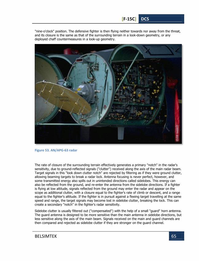
[F-15C] DCS
BELSIMTEK 65
"nine-o'clock" position. The defensive fighter is then flying neither towards nor away from the threat, and its closure is the same as that of the surrounding terrain in a look-down geometry, or any deployed chaff countermeasures in a look-up geometry.
Figure 53. AN/APG-63 radar
The rate of closure of the surrounding terrain effectively generates a primary "notch" in the radar's sensitivity, due to ground-reflected signals ("clutter") received along the axis of the main radar beam. Target signals in this "look down clutter notch" are rejected by filtering as if they were ground clutter, allowing beaming targets to break a radar lock. Antenna focusing is never perfect, however, and some transmitted energy also spills out in unintended directions called sidelobes. This energy can also be reflected from the ground, and re-enter the antenna from the sidelobe directions. If a fighter is flying at low altitude, signals reflected from the ground may enter the radar and appear on the scope as additional clutter, with a closure equal to the fighter's rate of climb or descent, and a range equal to the fighter's altitude. If the fighter is in pursuit against a fleeing target travelling at the same speed and range, the target signals may become lost in sidelobe clutter, breaking the lock. This can create a secondary "notch" in the fighter's radar sensitivity.
Sidelobe clutter is usually filtered out ("compensated") with the help of a small "guard" horn antenna. The guard antenna is designed to be more sensitive than the main antenna in sidelobe directions, but less sensitive along the axis of the main beam. Signals received on the main and guard channels are then compared and rejected as sidelobe clutter if they are stronger on the guard channel.

[F-15C] DCS
BELSIMTEK 66
The guard horn is attached to the slotted array in flat-plate radar antennas like the APG-63 and scans together with it for good compensation in all scan directions. In Russian Cassegrain radars like the N019 and N001 however, the guard horn is not attached to the scanning reflector but is rather fixed and aimed in a downward direction. Banking the fighter at low altitude during a radar lock on a fleeing target can thus rotate the compensation horn away from the ground, degrade the sidelobe compensation and break the lock due to ground clutter. During normal scanning operation in search mode, the entire radar Cassegrain antenna housing is roll-stabilized on a rotating gimbal to keep it oriented with the horizon. In this mode, search targets can be lost from the scope if the fighter roll exceeds the limits of the rotating gimbal (110-120 degrees angle of bank). MiG-29 and Su-27 pilots thus need to make careful decisions about operating altitude during an engagement, since high altitudes reduce sidelobe clutter to maximize their radar performance, but also allow look-down targets to more easily break lock by notching. F-15C pilots enjoy fewer restrictions in radar performance, and might make such decisions based instead on the effect that altitude has on missile performance.
All modern combat aircraft are equipped with radar warning systems (RWS). An RWS identifies the azimuth and type of radar system that is radiating. Having identified the type of the radar system, it is generally safe to assume the type (or class) of the weapon system that is carrying the radar.
Modern radars can operate in a great variety of modes, with different pulse repetition frequencies (PRF) and different scan zones. PRF is the number of radar pulses per second. Changing the PRF is used to increase the radar’s sensitivity when detecting targets flying at different aspect angles. High PRF is used to detect targets flying towards your aircraft (high aspect), medium PRF is used for targets with low closure rate or you are behind. In the default operation mode, the radar cycles between high and medium PRF to provide all target aspect detection. This is termed an interleaved mode. In search modes the radar operates in wide scan zones. In target track modes the radar operates with narrow azimuth zones. The radar changes to track mode after target lock on.
Many modern radars have a form of track while scan (TWS) mode. It provides simultaneous tracking of several targets. The main advantage of this mode is that it provides detailed information on a wide zone of the air space. However, no information is provided about targets outside of the scan zone. Target movements in this mode are often tracked through prediction. Although the scanning period is relatively short, high speed and maneuvering targets can perform a quick maneuver and leave the scan zone. On the radar display, the predicted trajectory of the target will be shown. The next update of the position is made only after a defined period of time and a track file has been built.
In track while scan mode there is detailed information on a great number of targets. However target position prediction in the time during the scan periods is used in this mode. The target can leave the survey zone by performing an unexpected maneuveur.
The radar of the F-15C in this simulation is the AN/APG-63(V)1 pulse doppler radar. Turn on the radar, press [I]. Radar information is then displayed on the Vertical Situation Indicator (VSD) in the top left portion of the front dash. The radar has several modes as described below.
Long Range Search (LRS) Mode The LRS [2] key mode is the primary radar mode for the F-15C for long-range acquisition and engagement. The pilot can set the acquisition range (10, 20, 40, 80, or 160 nautical miles) and change the azimuth width and elevation. The information regarding radar contact locations is displayed on the vertical situation display (VSD), but no information regarding the contacts speed, altitude and bearing are provided.
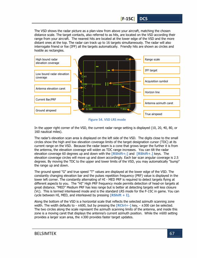
[F-15C] DCS
BELSIMTEK 67
The VSD shows the radar picture as a plan-view from above your aircraft, matching the chosen distance scale. The target contacts, also referred to as hits, are located on the VSD according their range from your aircraft. The nearest hits are located at the lower edge of the VSD and the more distant ones at the top. The radar can track up to 16 targets simultaneously. The radar will also interrogate friend or foe (IFF) all the targets automatically. Friendly hits are shown as circles and hostile as rectangles.
Figure 54. VSD LRS mode
In the upper right corner of the VSD, the current radar range setting is displayed (10, 20, 40, 80, or 160 nautical miles).
The radar’s elevation scan area is displayed on the left side of the VSD. The digits close to the small circles show the high and low elevation coverage limits of the target designation cursor (TDC) at its current range on the VSD. Because the radar beam is a cone that grows larger the further it is from the antenna, the elevation coverage will widen as TDC range increases. You can tilt the radar elevation coverage 60 degrees up and down with the [RShift+;] and [RShift+.] keys. The elevation coverage circles will move up and down accordingly. Each bar scan angular coverage is 2.5 degrees. By moving the TDC to the upper and lower limits of the VSD, you may automatically "bump" the range up and down.
The ground speed "G" and true speed "T" values are displayed at the lower edge of the VSD. The constantly changing elevation bar and the pulses repetition frequency (PRF) value is displayed in the lower left corner. The constantly alternating of HI - MED PRF is required to detect targets flying at different aspects to you. The "HI" High PRF frequency mode permits detection of head-on targets at great distance. "MED" Medium PRF has less range but is better at detecting targets will less closure (Vc). This is termed interleaved mode and is the standard LRS mode for the F-15C in game. You can cycle between HI, MED, and interleaved by pressing [RShift + I].
Along the bottom of the VSD is a horizontal scale that reflects the selected azimuth scanning zone width. The width defaults to - ±600, but by pressing the [RCtrl+-] key, - ±300 can be selected. The two circles along the scale represent the azimuth scanning limits of the antenna, and inside this zone is a moving caret that displays the antenna’s current azimuth position. While the ±600 setting provides a larger scan area, the ±300 provides faster target updates.
Low bound radar elevation
coverage
Antenna elevation caret
Current Bar/PRF
Ground airspeed
IFF target
Acquisition symbol
Horizon line
Antenna azimuth caret
True airspeed
High bound radar
elevation coverage
Range scale
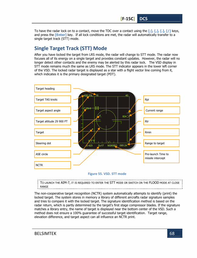
[F-15C] DCS
BELSIMTEK 68
To have the radar lock on to a contact, move the TDC over a contact using the [;], [,], [.], [/] keys, and press the [Enter] key. If all lock conditions are met, the radar will automatically transfer to a single target track (STT) mode.
Single Target Track (STT) Mode After you have locked the target from LRS mode, the radar will change to STT mode. The radar now focuses all of its energy on a single target and provides constant updates. However, the radar will no longer detect other contacts and the enemy may be alerted by this radar lock. The VSD display in STT mode remains much the same as LRS mode. The STT indicator appears in the lower left corner of the VSD. The locked radar target is displayed as a star with a flight vector line coming from it, which indicates it is the primary designated target (PDT).
Figure 55. VSD. STT mode
TO LAUNCH THE AIM-7, IT IS REQUIRED TO ENTER THE STT MODE OR SWITCH ON THE FLOOD MODE AT CLOSE
RANGE
The non-cooperative target recognition (NCTR) system automatically attempts to identify (print) the locked target. The system stores in memory a library of different aircrafts radar signature samples and tries to compare it with the locked target. The signature identification method is based on the radar return, which is partly determined by the target’s first stage compressor blades. If the signature matches a library entry, the name of target is displayed near the bottom center of the VSD. Such a method does not ensure a 100% guarantee of successful target identification. Target range, elevation difference, and target aspect can all influence an NCTR print.
Target heading
Target TAS knots
Target aspect angle
Target altitude 29 900 FT
Target
ASE circle
Steering dot
Rpi
Current range
NCTR
Rtr
Rmin
Pre-launch Time to
missile intercept
Range to target
[F-15C] DCS
BELSIMTEK 69
A target’s speed, aspect angle and heading are displayed along the upper left portion of the VSD. The target’s altitude is in displayed in relation to sea level along the elevation scale. An altitude of 29,900 feet would be displayed as 29-9. Additionally, target range and combined closure are displayed in the lower right portion of the VSD.
Missile employment data is provided in STT mode that provides you cues of when to take a shot. The large circle on the VSD is the allowable steering error (ASE) circle. This operates the same way as we reviewed with the HUD. The larger the circle, the larger the permissible steering error and probability of kill (Pk, pronounced P sub K). The ASE’s size depends on the selected missile, target maneuvers, target aspect, speed, etc. To ensure a higher Pk, try to remember the simple rhyme, "Center the dot for before taking the shot."
Along the right side of the VSD, a vertical scale is displayed that shows the selected weapon’s dynamic launch zone (DLZ) in relation to the locked target. Horizontal bars along the scale provide launch cues. From the bottom to top: Rmin – minimal launch range, Rtr – maximum launch range assuming high-G target maneuvering, Rpi – maximum launch range against a non-maneuvering target. At the top of the scale is a triangle that represents Raero. Raero symbolizes the missile’s maximum ballistic range regardless of target.
Below the scale, in the lower right portion of the VSD, target bearing and a digital readout of target range are displayed.
The estimated time it will take the selected missile to reach the target appears at the bottom of the VSD. The time in seconds will be preceded by an M if an AIM-120 is selected, a T if an AIM-7 is selected, or an S if an AIM-9 is selected. Note that post-launch information is only displayed on the HUD.
Track While Scan (TWS) Mode The TWS mode is a very informative mode, but is more complex than LRS. This mode combines the information unique to LRS and STT modes. It permits having detailed target data on a contact while still being able to scan for other targets. When TWS mode is initiated with the [RAlt-I] key, the mode indicator in the lower left corner of the VSD will change to "TWS." Generally, the TWS VSD display is very similar to the LRS VSD. However, each contact has a vector line that points in the direction of the contact’s heading and a digital altitude indication beside it.
YOU CAN USE TWS MODE FOR SIMULTANEOUS FIRING OF AIM-120 MISSILES AT MULTIPLE TARGETS.
In contrast to LRS where designating a contact transitions the radar to STT mode, an initial designation of a contact in TWS sets the contact as the primary designated target (PDT) but continues to search for and display additional contacts within the scan area. Further, by designating other contacts, these are set as secondary designation targets (SDT). SDT targets are indicated as hollow rectangles, whereas the PDT is displayed as a star-shape (as in STT mode). By designating either a PDT or SDT second time, an STT track on that target will be initiated. When multiple AIM-120 missiles are launched in volley, the first will go to the PDT and the following missiles will intercept the SDTs in the order they were designated. Time to intercept timers will be in regards to the PDT.

[F-15C] DCS
BELSIMTEK 70
Figure 56. TWS Mode
YOU CANNOT LAUNCH AN AIM-7 WHILE IN TWS MODE. TO LAUNCH SUCH A MISSILE, YOU MUST TO
TRANSITION TO STT MODE BY DESIGNATING A TARGET TWICE
TWS has several restrictions. The radar will attempt to build track files for each contact, but given a large scan volume, there will be a sizable refresh time between scans. During each scan the radar will try to predict the position of the contact for the next scan. If however the target takes evasive, high-G maneuvers and quickly changing its trajectory and speed, the radar can lose the track by making an incorrect track file prediction. Using such a defensive tactics, the hunter can quickly become the hunted. The radar though will try to center its azimuth scan on the PDT.
TWS, when combined with the AIM-120, provides a powerful ability to engage multiple targets simultaneously. Nevertheless, the target tracking reliability is less than that of LRS and even more so than STT. Unlike STT though, a TWS launch with AIM-120 will not provide the enemy aircraft with a radar lock and launch indication. As such, the first warning the enemy pilot will likely get is when the active radar seeker of the AIM-120 goes active near the target.
Home On Jam (HOJ) Mode When the radar and radar warning receiver (RWR) detects active electronic countermeasures (ECM), it displays on the VSD a vertical series of hollow rectangles along the azimuth of the jammer. This ECM indication is that of a noise jammer and is termed a strobe. In order to lock the target using its own ECM strobe, place the TDC on any of the hollow rectangles and press the [Enter] key to designate. Note that you are not locking a target on radar. Once the ECM emitter is locked, the series of rectangles will have a solid, vertical line running through them; the ECM emitter is along that azimuth.
The VSD is now in home on jam mode, the HOJ indicator appears on the VSD and HUD. The AIM-120 and AIM-7M missiles can both be launched in this mode when a radar lock is not possible due to enemy ECM. Note that when fired in this mode, the missile will fly a less efficient pure-pursuit trajectory and the probability of kill is much less. Also note that no range information is provided. As such, a call to a friendly AWACS is suggested to get ranging information. Attacking in such a mode provides the enemy with no warning because a HOJ attack is a completely passive attack.
Contacts
s PDT altitude
PDT
PDT azimuth
TWS mode indication
SDT altitude
SDT
Contact is friendly
Bearing on PDT
Range to PDT
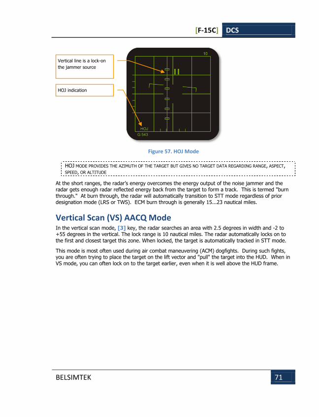
[F-15C] DCS
BELSIMTEK 71
Figure 57. HOJ Mode
HOJ MODE PROVIDES THE AZIMUTH OF THE TARGET BUT GIVES NO TARGET DATA REGARDING RANGE, ASPECT, SPEED, OR ALTITUDE
At the short ranges, the radar’s energy overcomes the energy output of the noise jammer and the radar gets enough radar reflected energy back from the target to form a track. This is termed "burn through." At burn through, the radar will automatically transition to STT mode regardless of prior designation mode (LRS or TWS). ECM burn through is generally 15...23 nautical miles.
Vertical Scan (VS) AACQ Mode In the vertical scan mode, [3] key, the radar searches an area with 2.5 degrees in width and -2 to +55 degrees in the vertical. The lock range is 10 nautical miles. The radar automatically locks on to the first and closest target this zone. When locked, the target is automatically tracked in STT mode.
This mode is most often used during air combat maneuvering (ACM) dogfights. During such fights, you are often trying to place the target on the lift vector and "pull" the target into the HUD. When in VS mode, you can often lock on to the target earlier, even when it is well above the HUD frame.
Vertical line is a lock-on
the jammer source
HOJ indication
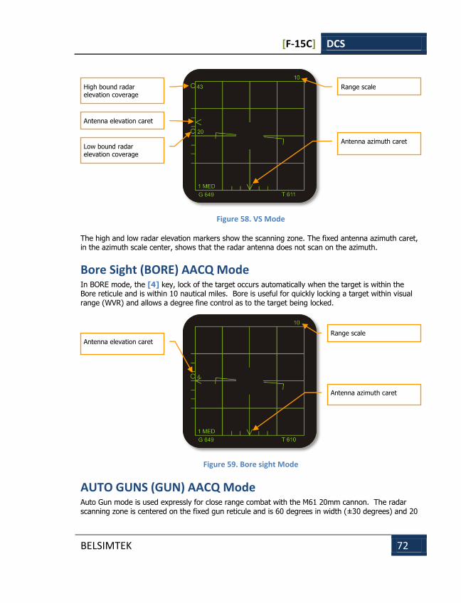
[F-15C] DCS
BELSIMTEK 72
Figure 58. VS Mode
The high and low radar elevation markers show the scanning zone. The fixed antenna azimuth caret, in the azimuth scale center, shows that the radar antenna does not scan on the azimuth.
Bore Sight (BORE) AACQ Mode In BORE mode, the [4] key, lock of the target occurs automatically when the target is within the Bore reticule and is within 10 nautical miles. Bore is useful for quickly locking a target within visual range (WVR) and allows a degree fine control as to the target being locked.
Figure 59. Bore sight Mode
AUTO GUNS (GUN) AACQ Mode Auto Gun mode is used expressly for close range combat with the M61 20mm cannon. The radar scanning zone is centered on the fixed gun reticule and is 60 degrees in width (±30 degrees) and 20
High bound radar elevation coverage
Antenna elevation caret
Low bound radar elevation coverage
Range scale
Antenna azimuth caret
Antenna elevation caret
Range scale
Antenna azimuth caret
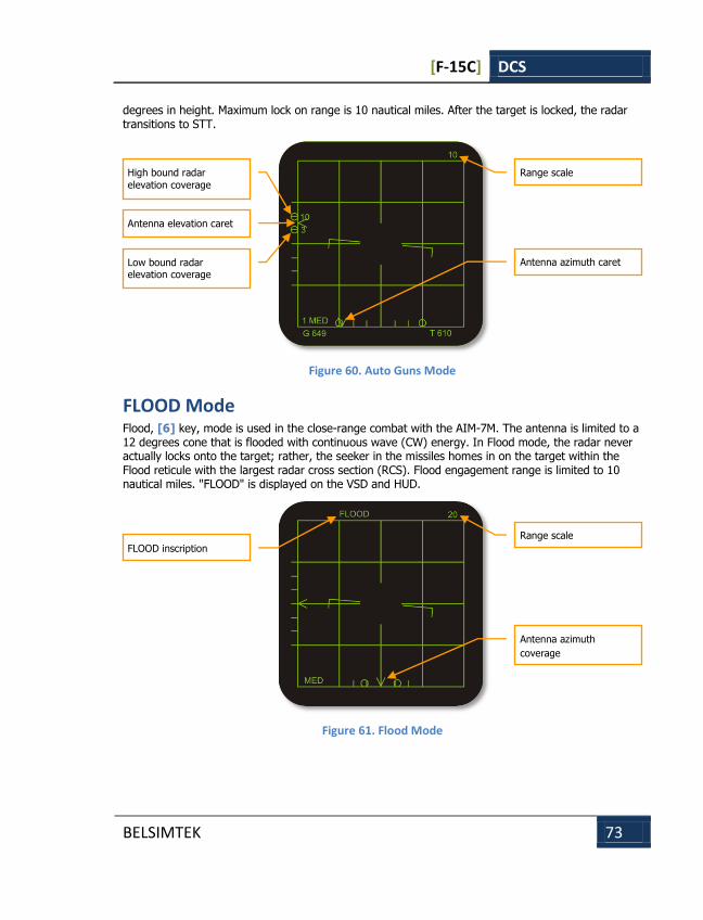
[F-15C] DCS
BELSIMTEK 73
degrees in height. Maximum lock on range is 10 nautical miles. After the target is locked, the radar transitions to STT.
Figure 60. Auto Guns Mode
FLOOD Mode Flood, [6] key, mode is used in the close-range combat with the AIM-7M. The antenna is limited to a 12 degrees cone that is flooded with continuous wave (CW) energy. In Flood mode, the radar never actually locks onto the target; rather, the seeker in the missiles homes in on the target within the Flood reticule with the largest radar cross section (RCS). Flood engagement range is limited to 10 nautical miles. "FLOOD" is displayed on the VSD and HUD.
Figure 61. Flood Mode
High bound radar
elevation coverage
Antenna elevation caret
Low bound radar elevation coverage
Range scale
Antenna azimuth caret
FLOOD inscription
Range scale
Antenna azimuth
coverage
[F-15C] DCS
BELSIMTEK 74
COUNTERMEASURE SYSTEMS
COUNTERMEASURE SYSTEMS
[F-15C] DCS
BELSIMTEK 75
COUNTERMEASURE SYSTEMS Electronic warfare (EW) is a deep and complex topic that covers a long history of opposing and rapidly evolving sensors, tactics, weapons and other equipment from numerous countries. In this section, we consider only a few active radar jamming electronic countermeasures (ECM) - or as it has been more recently called, "electronic attack" (EA) - systems that are designed to protect the aircraft on which they are installed. When the player-flown aircraft is equipped with such an ECM system (internally, or carried on a weapon station as a pod), it can be toggled on and off during a mission by pressing the [E] key. The active jammer will then work to reduce the tracking range of enemy radars and degrade the performance of incoming radar-guided missiles. The player's use of such active ECM may come at a price, however. The ECM may interfere with the player's own radar-guided missiles during or after launch, hostile radars experiencing reduced tracking range may nevertheless enjoy increased detection range, and hostile missiles may see active ECM as a beacon, and pursue it in a secondary "Home On Jam" (HOJ) mode. For the best defense against missiles, active ECM is best combined together with passive jamming (chaff) and perpendicular ("beaming") maneuvers at low altitude.
AN/ALQ-135 Internal ECM System The AN/ALQ-135 internal ECM station entered service as an integrated element of the F-15 Eagle's Tactical Electronic Warfare System (TEWS), making the Eagle the first air superiority fighter designed from the start with internal space reserved for an active jamming suite.
The system is capable of producing both noise barrage and deception jamming signals to counter a variety of both fixed- and variable-frequency threat radars operating in the bands of 2 to 20 GHz (NATO E through J bands). The transmitting antennas provide 360 coverage for protection against
radar guided "surface-to-air" (SAM) and "air-to-air" (AAM) missiles. The system features 20 re-programmable processors working in parallel, to ensure fast and flexible responsiveness to changes in the threat environment.
The AN/ALQ-135 jammer tunes itself according to threat data received from the AN/ALR-56C radar warning receiver, which is similarly integrated into the Eagle's TEWS.
In its original configuration, the AN/ALQ-135 consisted of six line-replaceable units (LRUs or "black boxes") - three oscillators and three amplifiers that generated the jamming signals for coverage in its overlapping Band 1 (NATO E through G) and Band 2 (NATO G through I).
The F-15C later received some of the F-15E Strike Eagle's AN/ALQ-135B equipment as an upgrade, providing coverage in Band 3 (NATO H through J) against modern short-range SAM, AAA and interceptor aircraft radars. Two new transmitting antennas were installed ahead of the windshield and ventrally, both behind the nose radome, together with a horn antenna installed in the starboard fuselage tail boom for rear hemisphere coverage. These were in addition to the existing "Band 1.5" (replacing Bands 1 and 2) transmitting blade antennas installed under the fuselage nose.
Despite the high operational tempo during Operation Desert Storm in 1991, no F-15 fighter equipped with the AN/ALQ-135 was shot down by radar guided SAMs or AAMs (two F-15E Strike Eagles, still lacking the F-15C's Band 1.5 coverage at the time, were lost to ground fire).
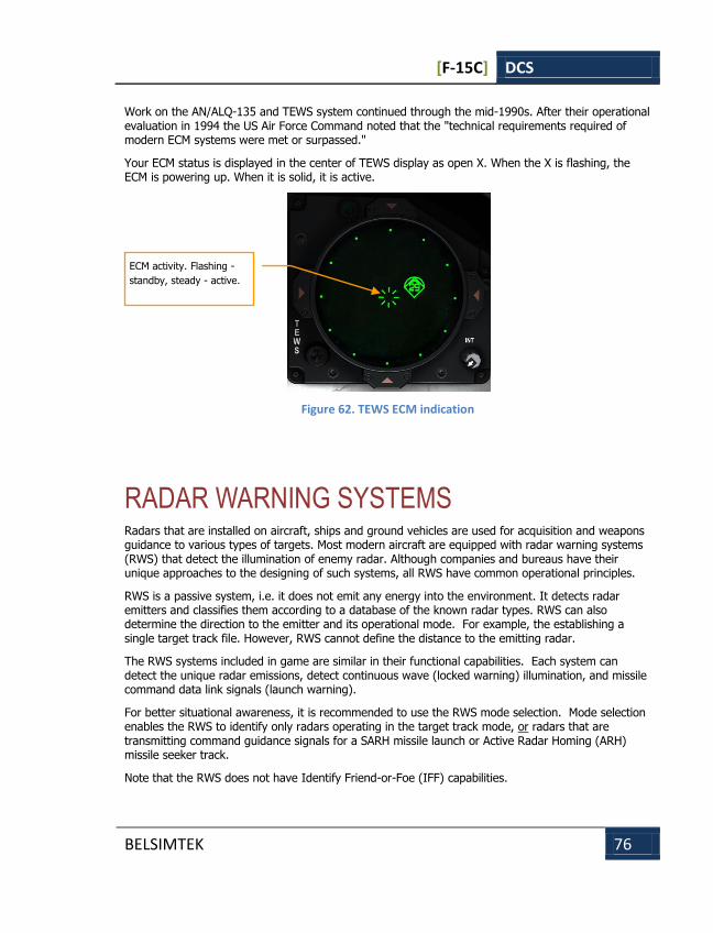
[F-15C] DCS
BELSIMTEK 76
Work on the AN/ALQ-135 and TEWS system continued through the mid-1990s. After their operational evaluation in 1994 the US Air Force Command noted that the "technical requirements required of modern ECM systems were met or surpassed."
Your ECM status is displayed in the center of TEWS display as open X. When the X is flashing, the ECM is powering up. When it is solid, it is active.
Figure 62. TEWS ECM indication
RADAR WARNING SYSTEMS Radars that are installed on aircraft, ships and ground vehicles are used for acquisition and weapons guidance to various types of targets. Most modern aircraft are equipped with radar warning systems (RWS) that detect the illumination of enemy radar. Although companies and bureaus have their unique approaches to the designing of such systems, all RWS have common operational principles.
RWS is a passive system, i.e. it does not emit any energy into the environment. It detects radar emitters and classifies them according to a database of the known radar types. RWS can also determine the direction to the emitter and its operational mode. For example, the establishing a single target track file. However, RWS cannot define the distance to the emitting radar.
The RWS systems included in game are similar in their functional capabilities. Each system can detect the unique radar emissions, detect continuous wave (locked warning) illumination, and missile command data link signals (launch warning).
For better situational awareness, it is recommended to use the RWS mode selection. Mode selection enables the RWS to identify only radars operating in the target track mode, or radars that are transmitting command guidance signals for a SARH missile launch or Active Radar Homing (ARH) missile seeker track.
Note that the RWS does not have Identify Friend-or-Foe (IFF) capabilities.
ECM activity. Flashing -
standby, steady - active.
[F-15C] DCS
BELSIMTEK 77
The RWS can use priority logic to determine a primary threat and a list of secondary threats in descending order:
1. The threat is either an ARH missile or if the missile command guidance signal is detected (missile launch);
2. The threat radar is transmitting in Single Target Track (STT) mode (or any other lock mode);
3. The threat has a priority based on a ‘common type’ of the threat. Here is the list of the types:
The threat is airborne radar;
The threat is a long-range radar;
The threat is a mid-range radar;
The threat is a short-range radar;
The threat is an early warning (EW) system;
The threat is an AWACS.
4. The threat is at maximum signal strength.
RWS DOES NOT DEFINE THE DISTANCE TO THE EMITTER
AN/ALR-56C Warning Receiver On the RWR scope, the center position indicates the location of your aircraft from a top-down perspective. Around the center position (your aircraft), radars that are illuminating your aircraft are displayed. An emitter above your aircraft on the scope indicates a radar in front of you, an emitter to the right of your aircraft is off your right wing, etc
The AN/ALR-56C RWR is a part of TEWS (Tactical Early Warning System) for the F-15C/D Eagle.
The RWR system provides a constant detection of radar signals between an azimuth - +/- 180, and an elevation range of - +/- 45.
The maximum number of threats on the RWR scope: 16.
The threat history duration display time: 7 seconds.
RWR function modes: All (acquisition) or Lock.
The radar emitter distance from the center of the RWR scope corresponds to the emitter’s signal strength. Radars emitting with greater power are shown closer to the center of the scope.
Early warning radars and AWACS symbols will never be displayed in the inner ring area.

[F-15C] DCS
BELSIMTEK 78
When a new threat is detected, a high pitched audio tone is heard once, and the threat symbol displays a hemisphere mark above the symbol.
When the RWR detects a radar in acquisition mode, a chirp audio tone will be heard.
When a threat locks on to your aircraft, the RWR tone will change from a periodic chirp to a constant chirping sound.
Figure 63. F-15C TEWS display symbology
The above image shows an example situation on the TEWS display.
At 12 o’clock, your aircraft is being illuminated by the acquisition radar (Snow Drift) of a "Buk" SAM system.
From 1 o’clock, your aircraft is being illuminated by an 64N6E (Big Bird) acquisition radar and a 40V6MD (Clam Shell) low-altitude acquisition radar tower. Both of these radars are part of a S-300PS SAM (SA-10C) battery.
From 2 o’clock, your aircraft is being illuminated by a ship-borne radar of a "Neustrashimy"-class patrol ship. Because it is a newly detected emitter, it has the semi-circle above it.
From 3 o’clock, your aircraft is being illuminated by an A-50U AWACS.
The primary threat, enclosed in a "diamond", is a MiG-29 between 10 and 11 o’clock.
From above analysis, we can draw the conclusion that the primary threat is MiG-29 that can employ a weapon any time. Consequently, it is necessary to either go offensive against this threat, or exit the area and deny the MiG a shot. An attack on the MiG could be performed independently or with the help of wingmen.
In addition to the MiG-29, the S-300 complex presents a potential threat. It is located at 1 o’clock, relative to your aircraft. When planning future maneuvers, the possibility of entering into the SAM’s launch zone must be considered.
Buk 9S18M1, SA-11 Snow
Drift
MiG-29 aircraft
«Diamond» - primary
threat mark
S-300PS 40V6MD, SA-10
Clam Shell
S-300PS 64N6E, SA-10
Big Bird
Upper semi-circle – new
threat mark
«Neustrashimy» - SA-N-9,
SA-N-11
AWАCS A-50
«Hat» - airborne threat
mark
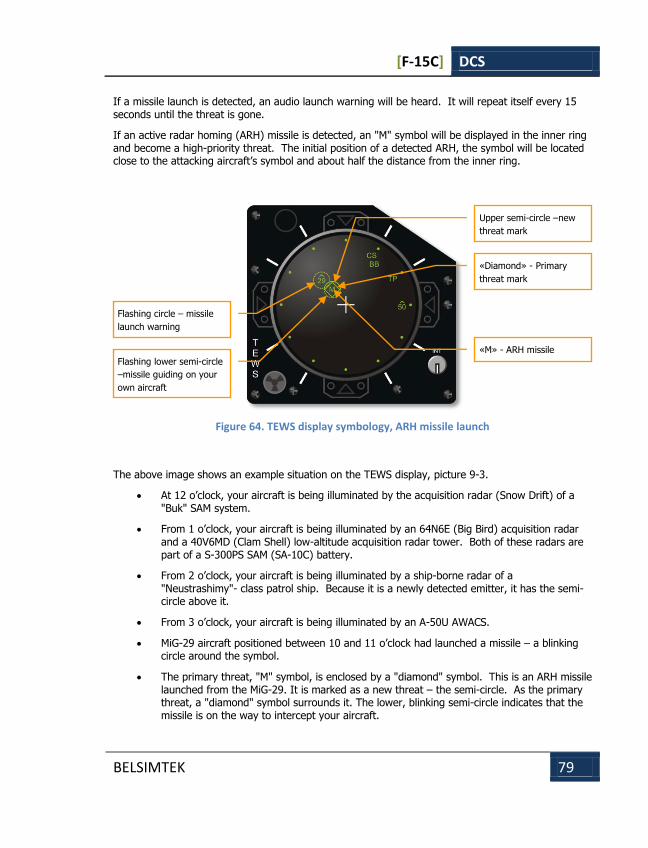
[F-15C] DCS
BELSIMTEK 79
If a missile launch is detected, an audio launch warning will be heard. It will repeat itself every 15 seconds until the threat is gone.
If an active radar homing (ARH) missile is detected, an "M" symbol will be displayed in the inner ring and become a high-priority threat. The initial position of a detected ARH, the symbol will be located close to the attacking aircraft’s symbol and about half the distance from the inner ring.
Figure 64. TEWS display symbology, ARH missile launch
The above image shows an example situation on the TEWS display, picture 9-3.
At 12 o’clock, your aircraft is being illuminated by the acquisition radar (Snow Drift) of a "Buk" SAM system.
From 1 o’clock, your aircraft is being illuminated by an 64N6E (Big Bird) acquisition radar and a 40V6MD (Clam Shell) low-altitude acquisition radar tower. Both of these radars are part of a S-300PS SAM (SA-10C) battery.
From 2 o’clock, your aircraft is being illuminated by a ship-borne radar of a "Neustrashimy"- class patrol ship. Because it is a newly detected emitter, it has the semi-circle above it.
From 3 o’clock, your aircraft is being illuminated by an A-50U AWACS.
MiG-29 aircraft positioned between 10 and 11 o’clock had launched a missile – a blinking circle around the symbol.
The primary threat, "М" symbol, is enclosed by a "diamond" symbol. This is an ARH missile launched from the MiG-29. It is marked as a new threat – the semi-circle. As the primary threat, a "diamond" symbol surrounds it. The lower, blinking semi-circle indicates that the missile is on the way to intercept your aircraft.
Flashing circle – missile
launch warning
Upper semi-circle –new
threat mark
«Diamond» - Primary
threat mark
«M» - ARH missile
Flashing lower semi-circle
–missile guiding on your
own aircraft
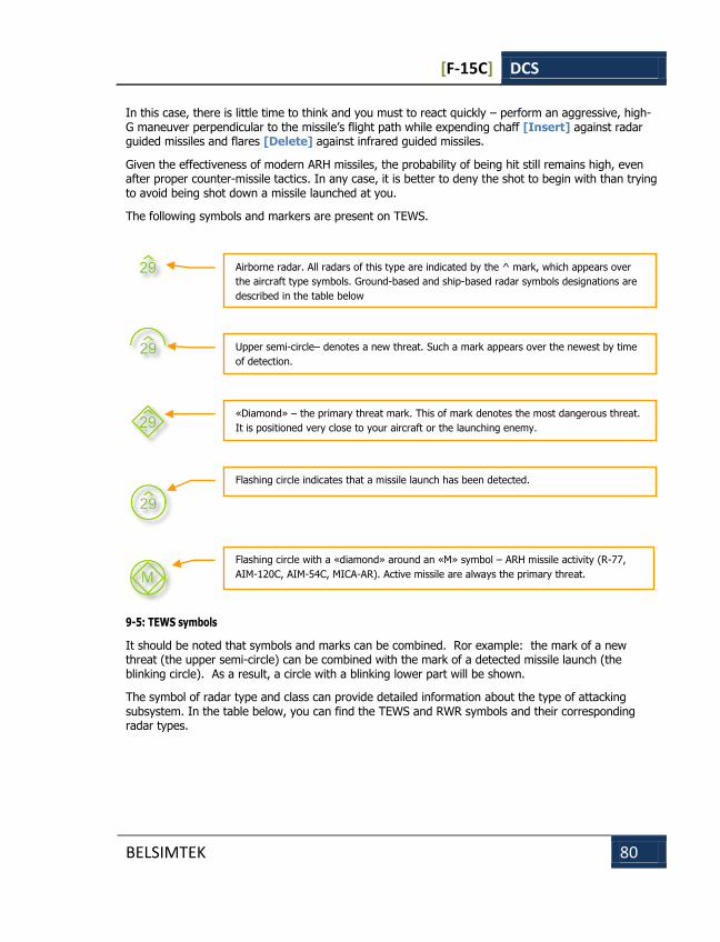
[F-15C] DCS
BELSIMTEK 80
In this case, there is little time to think and you must to react quickly – perform an aggressive, high-G maneuver perpendicular to the missile’s flight path while expending chaff [Insert] against radar guided missiles and flares [Delete] against infrared guided missiles.
Given the effectiveness of modern ARH missiles, the probability of being hit still remains high, even after proper counter-missile tactics. In any case, it is better to deny the shot to begin with than trying to avoid being shot down a missile launched at you.
The following symbols and markers are present on TEWS.
9-5: TEWS symbols
It should be noted that symbols and marks can be combined. Ror example: the mark of a new threat (the upper semi-circle) can be combined with the mark of a detected missile launch (the blinking circle). As a result, a circle with a blinking lower part will be shown.
The symbol of radar type and class can provide detailed information about the type of attacking subsystem. In the table below, you can find the TEWS and RWR symbols and their corresponding radar types.
Airborne radar. All radars of this type are indicated by the ^ mark, which appears over
the aircraft type symbols. Ground-based and ship-based radar symbols designations are
described in the table below
Upper semi-circle– denotes a new threat. Such a mark appears over the newest by time
of detection.
«Diamond» – the primary threat mark. This of mark denotes the most dangerous threat.
It is positioned very close to your aircraft or the launching enemy.
Flashing circle indicates that a missile launch has been detected.
Flashing circle with a «diamond» around an «M» symbol – ARH missile activity (R-77,
AIM-120C, AIM-54C, MICA-AR). Active missile are always the primary threat.
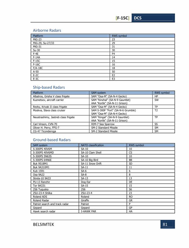
[F-15C] DCS
BELSIMTEK 81
Airborne Radars Platform RWS symbol
MiG-23 23
MiG-29, Su-27/33 29
MiG-31 31
Su-30 30
F-4E F4
F-14A 14
F-15C 15
F-16C 16
F/A-18C 18
A-50 50
E-2C E2
E-3C E3
Ship-based Radars Platform SAM system RWS symbol
Albatros, Grisha V class frigate SAM "Osa-M" (SA-N-4 Gecko) HP
Kuznetsov, aircraft carrier SAM "Kinzhal" (SA-N-9 Gauntlet) AAA "Kortik" (SA-N-11 Grison)
SW
Rezky, Krivak II class frigate SAM "Osa-M" (SA-N-4 Gecko) TP
Moskva, Slava class cruiser SAM S-300F "Fort" (SA-N-6 Grumble)
SAM "Osa-M" (SA-N-4 Gecko)
T2
Neustrashimy, Jastreb class frigate SAM "Kingal" (SA-N-9 Gauntlet)
AAA "Kortik" (SA-N-11 Grison)
TP
Carl Vinson, CVN-70 RIM-7 Sea Sparrow SS
Oliver H. Perry, FFG-7 SM-2 Standard Missile SM
CG-47 Ticonderoga SM-2 Standard Missile SM
Ground-based Radars SAM system NATO classification RWS symbol
S-300PS 40V6M SA-10 10
S-300PS 40V6MD SA-10 Clam Shell CS
S-300PS 5N63S SA-10 10
S-300PS 64N6E SA-10 Big Bird BB
Buk 9S18M1 SA-11 Snow Drift SD
Buk 9A310M1 SA-11 11
Kub 1S91 SA-6 6
Osa 9A22 SA-8 8
Strela-10 9A33 SA-13 13
PU-13 Ranzhir Dog Ear DE
Tor 9A331 SA-15 15
2S6 Tuguska 2S6 S6
ZSU-23-4 Shilka ZSU-23-4 23
Roland ADS Roland RO
Roland Radar Giraffe GR
Patriot search and track radar Patriot P
Gepard Gepard GP
Hawk search radar I-HAWK PAR HA

[F-15C] DCS
BELSIMTEK 82
Hawk track radar I-HAWK HPI H
Vulcan M-163 VU
S-125 P-19 radar SA-3 Flat Face B FF
S-125 SNR SA-3 Low Blow LB

[F-15C] DCS
BELSIMTEK 83
AIR-TO-AIR MISSILES AIR-TO-AIR MISSILES
[F-15C] DCS
BELSIMTEK 84
AIR-TO-AIR MISSILES All modern fighters, and most attack aircraft, are equipped with air-to-air missiles (AAM). Though possessing significant advantages over cannons, they have many operational limitations. For the successful launch of any missile, one has to strictly follow defined sequences. There are unique, pre-launch steps for each type of a missile.
AAMs are a collection of integrated components that consist of the seeker, the warhead, and the motor. Motor burn can only last for a limited amount of time. This usually ranges from 2 to 20 seconds, depending on the missile type.
At launch, the missile accelerates to its maximum flight speed. After the motor is depleted, the missile consumes the energy acquired in the acceleration. The higher the initial airspeed at the moment of the missile launch, the greater the airspeed of the missile and the longer its launch range will be. An increase in launch aircraft speed corresponds to a longer missile range.
The missile launch range, or missile employment zone (MEZ), is greatly influenced by the aircraft’s altitude at the moment of missile launch. This is due to the much denser air at lower altitude. If the flight altitude is increased by 20,000 feet, the maximum launch range is about doubled. For example, the AIM-120’s launch range at of 20,000 feet is twice as great as when launched at sea level. When attacking a target higher or lower than one’s aircraft, the maximum missile launch range is equivalent to the maximum launch range of the average altitude between the two aircraft.
TO INCREASE A MISSILE’S MAXIMUM LAUNCH RANGE, YOU SHOULD LAUNCH FROM HIGH ALTITUDES
Target aspect angle can also greatly influences a missile’s MEZ. The launch range increases when you and the target are flying towards each other. This is termed a high aspect engagement. When you attempt to attack a target from behind, the target is flying away from you and greatly reduces a missile’s MEZ. This is termed a low aspect engagement. To increase the range of your attacks, attempt high aspect intercepts.
YOU SHOULD TRY TO ATTACK ONCOMING TARGETS. THIS WILL INCREASE YOUR MISSILE LAUNCH RANGE.
Missiles fly according to the same physical laws as aircraft. When maneuvering, the missile consumes energy when it pulls G. A maneuvering target can make the missile make significant course corrections and thereby consume the missile’s energy. This can lead to the missile being incapable of continuing the intercept.
AT LONG RANGES. SLOW MANEUVERING TARGETS ARE MORE EASILY HIT.
Air-to-air missiles are intended to destroy aircraft. They are divided into several classes, according to their range and guidance principles. According to the range:
Short range missiles. Less than 15 km. (R-73, R-60, AIM-9 and others)
Medium range missiles. From 15 km up to 75 km. (R-27, R-77, AIM-7, AIM-120, and others)
Long range missiles. Over 75 km. (R-33, AIM-54, and others)
These missiles use a variety of guidance systems:
Passive infrared. Infrared target seeker (R-60, R-73, R-27Т, AIM-9)
[F-15C] DCS
BELSIMTEK 85
Passive radar. Radar emitter targeting, is usually combined with semi-active or active targeting. It is a targeting mode modern missiles such as AIM-7M, AIM-120, and R-27R can use. This is sometimes referred to as Home On Jam (HOJ) mode.
Semi-Active Radar Homing (SARH). Such seekers home in on the reflected radar energy from the launch aircraft’s continuous wave radar. (R-27R/ER, AIM-7, R-33)
Active Radar Homing (ARH). Active systems have their own radar seekers built into the missile. (R-77, AIM-120, AIM-54)
Medium and long range missiles are often fitted with an inertial navigation systems (INS) and a command-guidance transmitter/receiver (data link). This enables such systems to be launched towards a target’s position that is further than the supporting radar can lock and illuminate.
Passive radar and infrared homing systems do not radiate an active signal. Instead, they guide to the target by locking on to the target’s radar or infrared emissions. These are "fire-and-forget" missiles, i.e. they are fully automated after launch.
Semi-active missiles home in on the reflected radar energy of a target. For such missiles, it is necessary that the supporting aircraft retain radar lock until the missile hits the target. This can often lead to "jousting" of SARH armed aircraft.
Active missiles at long ranges have the same features as semi-active systems; i. e. the launch aircraft must track the target and provide guidance to the missile. Once the missile is within 10 to 20 km of the target, the onboard radar seeker activates and continues the intercept without need of support from the launch aircraft’s radar. Such systems have only recently been introduced into service.
AAMs fly according to the same aerodynamics laws as aircraft. They are affected by the same gravitational and drag force that affect aircraft. For a missile to fly, it must also generate lift forces. Due to the small size of AAM wings though, lift is generally generated by speed rather than wing form.
After launch, the missile is accelerated by its motor. This is generally a solid propellant motor that operates from 2 to 15 seconds. During this period, the missile accelerates up to Mach 2 -3 and then continues flight based on the stored kinetic energy to overcome drag and gravity. As airspeed decreases, it becomes increasingly difficult for the missile to maneuver due to the decreased efficiency of its control surfaces. When the missile’s speed falls below 1,000 – 800 km/h, it becomes almost uncontrollable and will continue to fly ballisticly until it hits the ground or self destructs.
Maximum missile launch range is not a constant value; it depends on a number of variables: initial median flight altitudes, combined air speeds, and target aspect angle. To attain a missile’s maximum launch range, it is best to launch at high altitude, at high airspeed, in a high aspect intercept. Note that launch range does not necessarily equate to missile flight range. For example, in a high aspect encounter where the missile is launched at 50 km, the missile will only travel about 30-35 km. This is because the target is flying towards the missile. Near ground level where the air density is very high, the launch range is more than halved.
When attacking an enemy from the rear, the launch range significantly decreases because the missile has to catch up with a target that is flying away. Rear hemisphere, low aspect, launch ranges are usually two to three times less than high aspect launch ranges. For example, these are the launch ranges of the R-27ER at different aspects and altitudes:
Maximum forward hemisphere launch range at the altitude of 10 000 m. – 66 km.
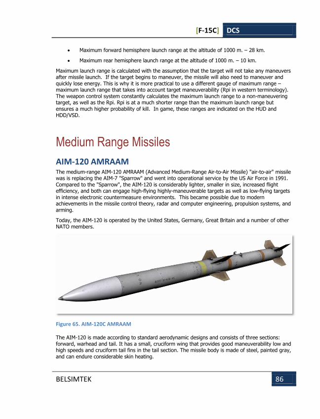
[F-15C] DCS
BELSIMTEK 86
Maximum forward hemisphere launch range at the altitude of 1000 m. – 28 km.
Maximum rear hemisphere launch range at the altitude of 1000 m. – 10 km.
Maximum launch range is calculated with the assumption that the target will not take any maneuvers after missile launch. If the target begins to maneuver, the missile will also need to maneuver and quickly lose energy. This is why it is more practical to use a different gauge of maximum range – maximum launch range that takes into account target maneuverability (Rpi in western terminology). The weapon control system constantly calculates the maximum launch range to a non-maneuvering target, as well as the Rpi. Rpi is at a much shorter range than the maximum launch range but ensures a much higher probability of kill. In game, these ranges are indicated on the HUD and HDD/VSD.
Medium Range Missiles
AIM-120 AMRAAM The medium-range AIM-120 AMRAAM (Advanced Medium-Range Air-to-Air Missile) "air-to-air" missile was is replacing the AIM-7 "Sparrow" and went into operational service by the US Air Force in 1991. Compared to the "Sparrow", the AIM-120 is considerably lighter, smaller in size, increased flight efficiency, and both can engage high-flying highly-maneuverable targets as well as low-flying targets in intense electronic countermeasure environments. This became possible due to modern achievements in the missile control theory, radar and computer engineering, propulsion systems, and arming.
Today, the AIM-120 is operated by the United States, Germany, Great Britain and a number of other NATO members.
Figure 65. AIM-120C AMRAAM
The AIM-120 is made according to standard aerodynamic designs and consists of three sections: forward, warhead and tail. It has a small, cruciform wing that provides good maneuverability low and high speeds and cruciform tail fins in the tail section. The missile body is made of steel, painted gray, and can endure considerable skin heating.
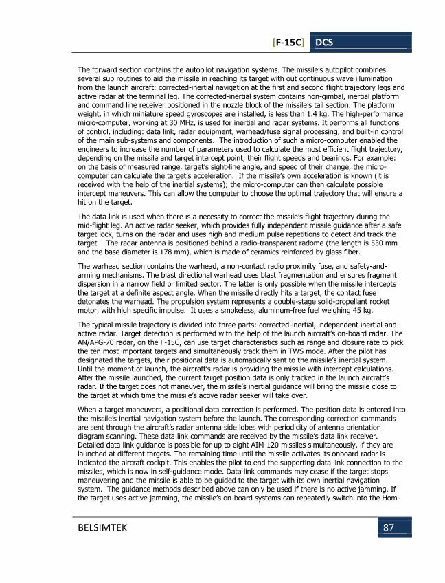
[F-15C] DCS
BELSIMTEK 87
The forward section contains the autopilot navigation systems. The missile’s autopilot combines several sub routines to aid the missile in reaching its target with out continuous wave illumination from the launch aircraft: corrected-inertial navigation at the first and second flight trajectory legs and active radar at the terminal leg. The corrected-inertial system contains non-gimbal, inertial platform and command line receiver positioned in the nozzle block of the missile’s tail section. The platform weight, in which miniature speed gyroscopes are installed, is less than 1.4 kg. The high-performance micro-computer, working at 30 MHz, is used for inertial and radar systems. It performs all functions of control, including: data link, radar equipment, warhead/fuse signal processing, and built-in control of the main sub-systems and components. The introduction of such a micro-computer enabled the engineers to increase the number of parameters used to calculate the most efficient flight trajectory, depending on the missile and target intercept point, their flight speeds and bearings. For example: on the basis of measured range, target’s sight-line angle, and speed of their change, the micro-computer can calculate the target’s acceleration. If the missile’s own acceleration is known (it is received with the help of the inertial systems); the micro-computer can then calculate possible intercept maneuvers. This can allow the computer to choose the optimal trajectory that will ensure a hit on the target.
The data link is used when there is a necessity to correct the missile’s flight trajectory during the mid-flight leg. An active radar seeker, which provides fully independent missile guidance after a safe target lock, turns on the radar and uses high and medium pulse repetitions to detect and track the target. The radar antenna is positioned behind a radio-transparent radome (the length is 530 mm and the base diameter is 178 mm), which is made of ceramics reinforced by glass fiber.
The warhead section contains the warhead, a non-contact radio proximity fuse, and safety-and-arming mechanisms. The blast directional warhead uses blast fragmentation and ensures fragment dispersion in a narrow field or limited sector. The latter is only possible when the missile intercepts the target at a definite aspect angle. When the missile directly hits a target, the contact fuse detonates the warhead. The propulsion system represents a double-stage solid-propellant rocket motor, with high specific impulse. It uses a smokeless, aluminum-free fuel weighing 45 kg.
The typical missile trajectory is divided into three parts: corrected-inertial, independent inertial and active radar. Target detection is performed with the help of the launch aircraft’s on-board radar. The AN/APG-70 radar, on the F-15C, can use target characteristics such as range and closure rate to pick the ten most important targets and simultaneously track them in TWS mode. After the pilot has designated the targets, their positional data is automatically sent to the missile’s inertial system. Until the moment of launch, the aircraft’s radar is providing the missile with intercept calculations. After the missile launched, the current target position data is only tracked in the launch aircraft’s radar. If the target does not maneuver, the missile’s inertial guidance will bring the missile close to the target at which time the missile’s active radar seeker will take over.
When a target maneuvers, a positional data correction is performed. The position data is entered into the missile’s inertial navigation system before the launch. The corresponding correction commands are sent through the aircraft’s radar antenna side lobes with periodicity of antenna orientation diagram scanning. These data link commands are received by the missile’s data link receiver. Detailed data link guidance is possible for up to eight AIM-120 missiles simultaneously, if they are launched at different targets. The remaining time until the missile activates its onboard radar is indicated the aircraft cockpit. This enables the pilot to end the supporting data link connection to the missiles, which is now in self-guidance mode. Data link commands may cease if the target stops maneuvering and the missile is able to be guided to the target with its own inertial navigation system. The guidance methods described above can only be used if there is no active jamming. If the target uses active jamming, the missile’s on-board systems can repeatedly switch into the Hom-

[F-15C] DCS
BELSIMTEK 88
On-Jam (HOJ) guidance mode when in the middle and final trajectory legs. In close air combat when the target is visible active radar guidance mode is used.
The AIM-120 can be loaded on two different launch-type devices: rail guides and forced ejection with the help of squibs. The first is constructed such that even AIM-9 "Sidewinder" can be loaded on them. The second type of device requires a modified to the existing LAU-17 and LAU-92 launchers. The F-15 and F-18 are equipped with such launchers. The can be used for both AIM-7 "Sparrow" and AIM-120 loading. Thee devices allow six missiles on F-15, F-16, F-18 and Tornado F.2, and four on the Phantom F-4F.
Figure 66. AIM-120B
Figure 67. AIM-120C
Today, there are three AIM-120 models:
AIM-120A is the first version of the missile; it was produced until 1994.
AIM-120B is a modernized version of the A model with greater programmability via the cable jack in the transport container.
AIM-120C has been in production since 1996, and has been modified to be loaded on the F/A-22A. The C model has a reduced size, improved speed, better maneuverability and greater range than earlier models.
A small number of F/A-18 fighters, equipped with the AIM-120, were transferred to the Persian Gulf region as part of operation "Desert Storm." However, the missile did not see use in combat. The
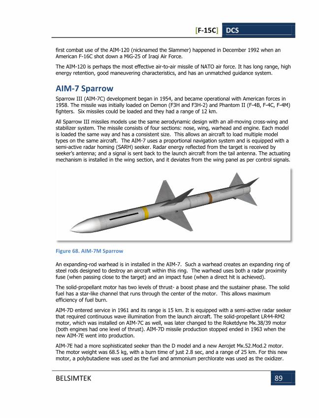
[F-15C] DCS
BELSIMTEK 89
first combat use of the AIM-120 (nicknamed the Slammer) happened in December 1992 when an American F-16C shot down a MiG-25 of Iraqi Air Force.
The AIM-120 is perhaps the most effective air-to-air missile of NATO air force. It has long range, high energy retention, good maneuvering characteristics, and has an unmatched guidance system.
AIM-7 Sparrow Sparrow III (AIM-7C) development began in 1954, and became operational with American forces in 1958. The missile was initially loaded on Demon (F3H and F3H-2) and Phantom II (F-4B, F-4C, F-4M) fighters. Six missiles could be loaded and they had a range of 12 km.
All Sparrow III missiles models use the same aerodynamic design with an all-moving cross-wing and stabilizer system. The missile consists of four sections: nose, wing, warhead and engine. Each model is loaded the same way and has a consistent size. This allows an aircraft to load multiple model types on the same aircraft. The AIM-7 uses a proportional navigation system and is equipped with a semi-active radar homing (SARH) seeker. Radar energy reflected from the target is received by seeker’s antenna; and a signal is sent back to the launch aircraft from the tail antenna. The actuating mechanism is installed in the wing section, and it deviates from the wing panel as per control signals.
Figure 68. AIM-7M Sparrow
An expanding-rod warhead is in installed in the AIM-7. Such a warhead creates an expanding ring of steel rods designed to destroy an aircraft within this ring. The warhead uses both a radar proximity fuse (when passing close to the target) and an impact fuse (when a direct hit is achieved).
The solid-propellant motor has two levels of thrust- a boost phase and the sustainer phase. The solid fuel has a star-like channel that runs through the center of the motor. This allows maximum efficiency of fuel burn.
AIM-7D entered service in 1961 and its range is 15 km. It is equipped with a semi-active radar seeker that required continuous wave illumination from the launch aircraft. The solid-propellant LR44-RM2 motor, which was installed on AIM-7C as well, was later changed to the Roketdyne Мк.38/39 motor (both engines had one level of thrust). AIM-7D missile production stopped ended in 1963 when the new AIM-7E went into production.
AIM-7E had a more sophisticated seeker than the D model and a new Aerojet Мк.52.Mod.2 motor. The motor weight was 68.5 kg, with a burn time of just 2.8 sec, and a range of 25 km. For this new motor, a polybutadiene was used as the fuel and ammonium perchlorate was used as the oxidizer.

[F-15C] DCS
BELSIMTEK 90
Thanks to the new motor, the missile could develop high speeds and greater ranges than older models of the AIM-7. The extended range was also due to the improved seeker.
Based on the AIM-7E, the navalized "Sea Sparrow" was developed, which has been used as a defensive system for ships of the United States and several other countries. Later, the AIM-7E was included as the basis for several NATO air defense systems: "Spada" (ground) and "Albatros" (ship-borne). Many countries have also developed their own "air-to-air" missiles based on the AIM-7E. Successful ground tests and good publicity brought world fame to AIM-7E missile.
However, the positive press did not match combat results. In Vietnam, from 1965 to 1969, only one AIM-7E launch out of ten hit their target. Combat experience revealed several deficiencies such as a large minimum range and the time-consuming process of locking a target. These missiles were particularly inefficient at hitting highly maneuverable targets. Given that AIM-7E was designed to engage lumbering, Soviet bombers at long range, these results are not surprising.
Following the Vietnam War, combat analysis spawned the development of a new Sparrow model began: the AIM-7E2. This modification went into operation in 1968 with a maximum engagement range of 50 km at high altitude.
When designing this model, great attention was paid to achieving the necessary characteristics needed in a within visual range engagement. They reduced the fuse device arming time, improved the seeker and enhanced the control system and control surface actuators. As a result, the new model was more maneuverable and had a reduced minimum engagement range.
By 1973, AIM-7F became operational. The maximum engagement range at high altitude was 50-70 km. Its seeker could operate in two modes: pulse-Doppler and continuous wave, which enabled the missile to be compatible with a multitude of radars.
The improved expanding-rod warhead had a greater blast range. Unlike previous modifications, the missile’s warhead is installed between the nose and the wing section. This became possible by reducing the space needed for instruments that previously used vacuum tubes with single computer chips to control the seeker, control systems and warhead. Additionally, this increased missile reliability – the equipment mean-time-between-failures amounted to 470 hours, which is eight times higher than AIM-7E.
The missile is equipped with a new two-level thrust motor, the Hercules Мk.58 Mod.2. With a significant increase of the range compared to the AIM-7E2, AIM-7F is better adapted for close range combat.
One shortcoming however was the AIM-7F’s low jamming resistance to radar signals reflected from the ground. This is especially important when attacking targets at low altitude in a look-down shoot-down situation. To solve this, work began in 1975 on an enhanced model of the AIM-7F. This new model would be equipped with a mono-pulse target seeking with better jamming resistance.
In 1976-77, the new AIM-7M under went flight tests. The maximum range at high altitude was 50-70 km. Nevertheless, in AIM-7M missile still had the shortcoming of relying on a semi-active radar homing (SARH) seeker. Such a seeker considerably limits the launch aircraft’s maneuverability by requiring target illumination (for 20-60 seconds if the target is beyond visual range and for 10-20 seconds if the target is visible) up to the moment of target impact. The SARH seeker is also quite vulnerable to modern electronic countermeasures. In fact, this prevents the realization of one of the main requirements of modern weapons – "fire-and-forget", i.e. independent guidance after launch.
The F-4, F-15, F-14, F-16, F/A-18 aircraft are equipped with this missile.
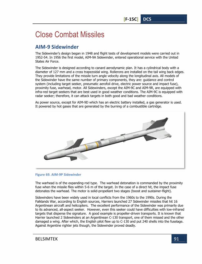
[F-15C] DCS
BELSIMTEK 91
Close Combat Missiles
AIM-9 Sidewinder The Sidewinder’s design began in 1948 and flight tests of development models were carried out in 1952-54. In 1956 the first model, AIM-9A Sidewinder, entered operational service with the United States Air Force.
The Sidewinder is designed according to canard aerodynamic plan. It has a cylindrical body with a diameter of 127 mm and a cross trapezoidal wing. Rollerons are installed on the tail wing back edges. They provide limitations of the missile turn angle velocity along the longitudinal axis. All models of the Sidewinder have the same number of primary components, they are: guidance and control system (including target seeker, pneumatic aerofoil drive, electric power source and impact fuse), proximity fuse, warhead, motor. All Sidewinders, except the AIM-9C and AIM-9R, are equipped with infra-red target seekers that are best used in good weather conditions. The AIM-9C is equipped with radar seeker; therefore, it can attack targets in both good and bad weather conditions.
As power source, except for AIM-9D which has an electric battery installed, a gas generator is used. It powered by hot gases that are generated by the burning of a combustible cartridge.
Figure 69. AIM-9P Sidewinder
The warhead is of the expanding-rod type. The warhead detonation is commanded by the proximity fuse when the missile flies within 5-6 m of the target. In the case of a direct hit, the impact fuse detonates the warhead. The motor is solid-propellant two stages (boost and sustainer-flight).
Sidewinders have been widely used in local conflicts from the 1960s to the 1990s. During the Falklands War, according to English sources, Harriers launched 27 Sidewinder missiles that hit 16 Argentinean aircraft and helicopters. The excellent performance of the Sidewinder was primarily due to its advanced, all-aspect seeker. However, even this seeker could have difficulties with low-infrared targets that disperse the signature. A good example is propeller-driven transports. It is known that Harrier launched 2 Sidewinders at an Argentinean С-130 transport, one of them missed and the other damaged a wing. After which, the English pilot flew up to С-130 and put 240 shells into the fuselage. Against Argentine righter jets though, the Sidewinder proved deadly.
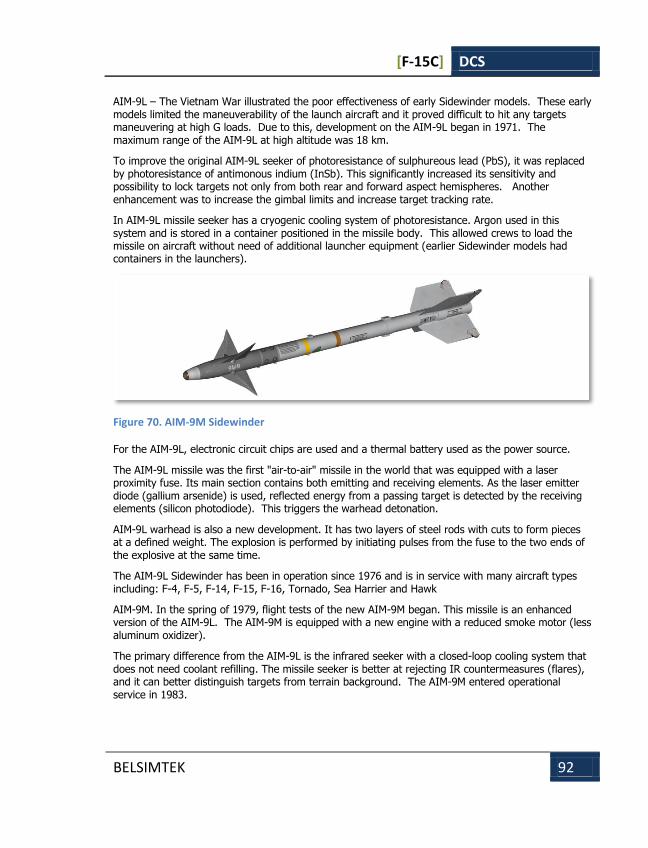
[F-15C] DCS
BELSIMTEK 92
AIM-9L – The Vietnam War illustrated the poor effectiveness of early Sidewinder models. These early models limited the maneuverability of the launch aircraft and it proved difficult to hit any targets maneuvering at high G loads. Due to this, development on the AIM-9L began in 1971. The maximum range of the AIM-9L at high altitude was 18 km.
To improve the original AIM-9L seeker of photoresistance of sulphureous lead (PbS), it was replaced by photoresistance of antimonous indium (InSb). This significantly increased its sensitivity and possibility to lock targets not only from both rear and forward aspect hemispheres. Another enhancement was to increase the gimbal limits and increase target tracking rate.
In AIM-9L missile seeker has a cryogenic cooling system of photoresistance. Argon used in this system and is stored in a container positioned in the missile body. This allowed crews to load the missile on aircraft without need of additional launcher equipment (earlier Sidewinder models had containers in the launchers).
Figure 70. AIM-9M Sidewinder
For the AIM-9L, electronic circuit chips are used and a thermal battery used as the power source.
The AIM-9L missile was the first "air-to-air" missile in the world that was equipped with a laser proximity fuse. Its main section contains both emitting and receiving elements. As the laser emitter diode (gallium arsenide) is used, reflected energy from a passing target is detected by the receiving elements (silicon photodiode). This triggers the warhead detonation.
AIM-9L warhead is also a new development. It has two layers of steel rods with cuts to form pieces at a defined weight. The explosion is performed by initiating pulses from the fuse to the two ends of the explosive at the same time.
The AIM-9L Sidewinder has been in operation since 1976 and is in service with many aircraft types including: F-4, F-5, F-14, F-15, F-16, Tornado, Sea Harrier and Hawk
AIM-9M. In the spring of 1979, flight tests of the new AIM-9M began. This missile is an enhanced version of the AIM-9L. The AIM-9M is equipped with a new engine with a reduced smoke motor (less aluminum oxidizer).
The primary difference from the AIM-9L is the infrared seeker with a closed-loop cooling system that does not need coolant refilling. The missile seeker is better at rejecting IR countermeasures (flares), and it can better distinguish targets from terrain background. The AIM-9M entered operational service in 1983.
[F-15C] DCS
BELSIMTEK 93
RADIO COMMUNICATIONS
AND MESSAGES
RADIO COMMUNICATIONS
AND MESSAGES
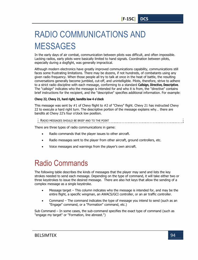
[F-15C] DCS
BELSIMTEK 94
RADIO COMMUNICATIONS AND
MESSAGES In the early days of air combat, communication between pilots was difficult, and often impossible. Lacking radios, early pilots were basically limited to hand signals. Coordination between pilots, especially during a dogfight, was generally impractical.
Although modern electronics have greatly improved communications capability, communications still faces some frustrating limitations. There may be dozens, if not hundreds, of combatants using any given radio frequency. When those people all try to talk at once in the heat of battle, the resulting conversations generally become jumbled, cut-off, and unintelligible. Pilots, therefore, strive to adhere to a strict radio discipline with each message, conforming to a standard Callsign, Directive, Descriptive. The "callsign" indicates who the message is intended for and who it is from, the "directive" contains brief instructions for the recipient, and the "descriptive" specifies additional information. For example:
Chevy 22, Chevy 21, hard right, bandits low 4 o’clock
This message was sent by #1 of Chevy flight to #2 of "Chevy" flight. Chevy 21 has instructed Chevy 22 to execute a hard right turn. The descriptive portion of the message explains why… there are bandits at Chevy 22’s four o’clock low position.
RADIO MESSAGES SHOULD BE BRIEF AND TO THE POINT
There are three types of radio communications in game:
Radio commands that the player issues to other aircraft.
Radio messages sent to the player from other aircraft, ground controllers, etc.
Voice messages and warnings from the player’s own aircraft.
Radio Commands The following table describes the kinds of messages that the player may send and lists the key strokes needed to send each message. Depending on the type of command, it will take either two or three keystrokes to issue the desired message. There are also hot keys that allow the sending of a complex message as a single keystroke.
Message target – This column indicates who the message is intended for, and may be the entire flight, a specific wingman, an AWACS/GCI controller, or an air traffic controller.
Command – The command indicates the type of message you intend to send (such as an "Engage" command, or a "Formation" command, etc.)
Sub Command – In some cases, the sub-command specifies the exact type of command (such as "engage my target" or "Formation, line abreast.")
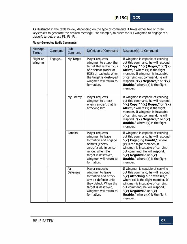
[F-15C] DCS
BELSIMTEK 95
As illustrated in the table below, depending on the type of command, it takes either two or three keystrokes to generate the desired message. For example, to order the #3 wingman to engage the player’s target, press F3, F1, F1.
Player-Generated Radio Commands
Message Target
Command Sub Command
Definition of Command Response(s) to Command
Flight or Wingmen
Engage... My Target Player requests wingmen to attack the target that is the focus of a sensor (radar or EOS) or padlock. When the target is destroyed, wingmen will return to formation.
If wingman is capable of carrying out this command, he will respond "(x) Copy," "(x) Roger," or "(x) Affirm," where (x) is the flight member. If wingman is incapable of carrying out command, he will respond, "(x) Negative," or "(x) Unable," where (x) is the flight member.
My Enemy Player requests wingmen to attack enemy aircraft that is attacking him.
If wingman is capable of carrying out this command, he will respond "(x) Copy," "(x) Roger," or "(x) Affirm," where (x) is the flight member. If wingman is incapable of carrying out command, he will respond, "(x) Negative," or "(x) Unable," where (x) is the flight member.
Bandits Player requests wingmen to leave formation and engage bandits (enemy aircraft) within sensor range. When the target is destroyed, wingmen will return to formation.
If wingman is capable of carrying out this command, he will respond "(x) Engaging bandit," where (x) is the flight member. If wingman is incapable of carrying out command, he will respond, "(x) Negative," or "(x) Unable," where (x) is the flight member.
Air Defenses
Player requests wingmen to leave formation and attack any air defense units they detect. When the target is destroyed, wingmen will return to formation.
If wingman is capable of carrying out this command, he will respond "(x) Attacking air defenses," where (x) is the flight member. If wingman is incapable of carrying out command, he will respond, "(x) Negative," or "(x) Unable," where (x) is the flight member.
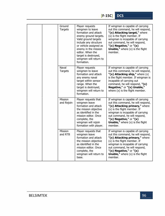
[F-15C] DCS
BELSIMTEK 96
Ground Targets
Player requests wingmen to leave formation and attack enemy ground targets. Valid ground targets include any structure or vehicle assigned as enemy in the mission editor. When the target is destroyed, wingmen will return to formation.
If wingman is capable of carrying out this command, he will respond, "(x) Attacking target," where (x) is the flight member. If wingman is incapable of carrying out command, he will respond, "(x) Negative," or "(x) Unable," where (x) is the flight member.
Naval Targets
Player requests wingmen to leave formation and attack any enemy naval target within sensor range. When the target is destroyed, wingmen will return to formation.
If wingman is capable of carrying out this command, he will respond, "(x) Attacking ship," where (x) is the flight member. If wingman is incapable of carrying out command, he will respond, "(x) Negative," or "(x) Unable," where (x) is the flight member.
Mission and Rejoin
Player requests that wingmen leave formation and attack the mission objective as identified in the mission editor. Once complete, the wingman will rejoin formation with player.
If wingman is capable of carrying out this command, he will respond, "(x) Attacking primary," where (x) is the flight member. If wingman is incapable of carrying out command, he will respond, "(x) Negative," or "(x) Unable," where (x) is the flight member.
Mission and RTB
Player requests that wingmen leave formation and attack the mission objective as identified in the mission editor. Once complete, the wingman will return to base.
If wingman is capable of carrying out this command, he will respond, "(x) Attacking primary," where (x) is the flight member. If wingman is incapable of carrying out command, he will respond, "(x) Negative," or "(x) Unable," where (x) is the flight member.

[F-15C] DCS
BELSIMTEK 97
Flight or Wingmen
Go to… Return To Base
Wingmen will leave formation and land at their designated airfield. If no airfield is designated, they will land at the nearest friendly airfield.
If wingman is capable of carrying out this command, he will respond, "(x) Copy," "(x) Roger," or "(x) Affirm," where (x) is the flight member. If wingman is incapable of carrying out command, he will respond, "(x) Negative," or "(x) Unable," where (x) is the flight member.
Route Wingmen will leave formation and proceed to route by mission editor plan.
If wingman is capable of carrying out this command, he will respond, "(x) Copy," "(x) Roger," or "(x) Affirm," where (x) is the flight member. If wingman is incapable of carrying out command, he will respond, "(x) Negative," or "(x) Unable," where (x) is the flight member.
Hold Position
Wingmen will leave formation and fly around current point.
If wingman is capable of carrying out this command, he will respond, "(x) Copy," "(x) Roger," or "(x) Affirm," where (x) is the flight member. If wingman is incapable of carrying out command, he will respond "(x) Negative," or "(x) Unable," where (x) is the flight member.
Flight or Wingmen
Radar… On Player requests that wingman to activate radar to search.
Wingman will respond, "(x) Radar On," where (x) is the flight member.
Off Player requests wingman to deactivate radar.
Wingman will respond, "(x) Radar Off," where (x) is the flight member.
Flight or Wingmen
ECM… On Player requests wingmen to activate ECM.
The wingman will respond, "(x) Music On," where (x) is the flight member.
Off Player requests wingmen to deactivate ECM.
Wingman will respond, "(x) Music Off," where (x) is the flight member.
Flight or Wingmen
Smoke On Player requests wingmen to activate smoke containers.
Wingman will activate smoke generators and respond, "(x) Copy," "(x) Roger," or "(x) Affirm," where (x) is the flight member.
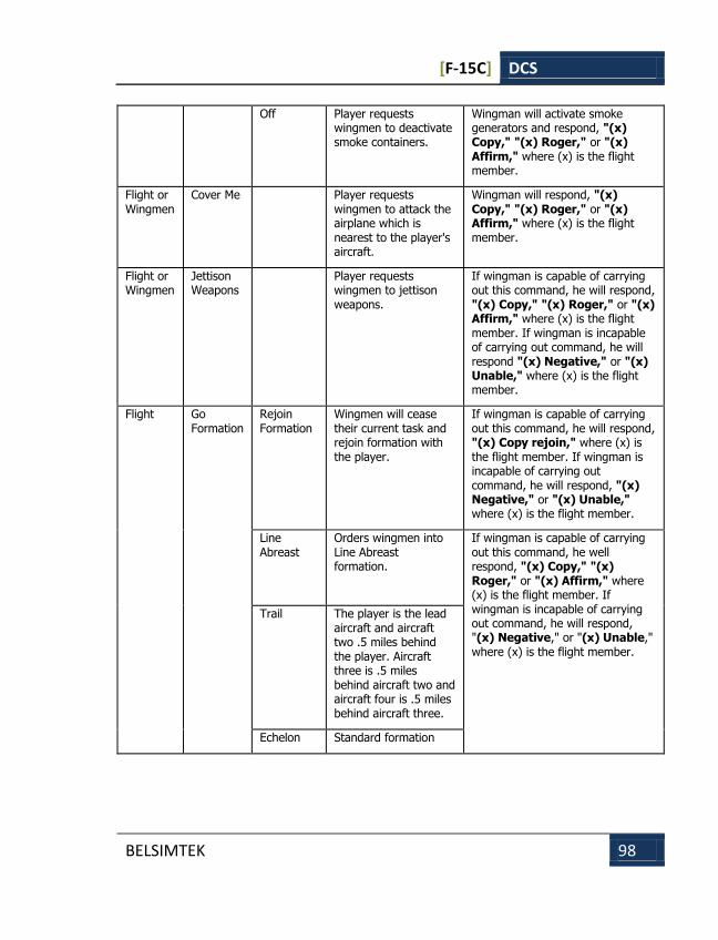
[F-15C] DCS
BELSIMTEK 98
Off Player requests wingmen to deactivate smoke containers.
Wingman will activate smoke generators and respond, "(x) Copy," "(x) Roger," or "(x) Affirm," where (x) is the flight member.
Flight or Wingmen
Cover Me Player requests wingmen to attack the airplane which is nearest to the player's aircraft.
Wingman will respond, "(x) Copy," "(x) Roger," or "(x) Affirm," where (x) is the flight member.
Flight or Wingmen
Jettison Weapons
Player requests wingmen to jettison weapons.
If wingman is capable of carrying out this command, he will respond, "(x) Copy," "(x) Roger," or "(x) Affirm," where (x) is the flight member. If wingman is incapable of carrying out command, he will respond "(x) Negative," or "(x) Unable," where (x) is the flight member.
Flight Go Formation
Rejoin Formation
Wingmen will cease their current task and rejoin formation with the player.
If wingman is capable of carrying out this command, he will respond, "(x) Copy rejoin," where (x) is the flight member. If wingman is incapable of carrying out command, he will respond, "(x) Negative," or "(x) Unable," where (x) is the flight member.
Line Abreast
Orders wingmen into Line Abreast formation.
If wingman is capable of carrying out this command, he well respond, "(x) Copy," "(x) Roger," or "(x) Affirm," where (x) is the flight member. If wingman is incapable of carrying out command, he will respond, "(x) Negative," or "(x) Unable," where (x) is the flight member.
Trail The player is the lead aircraft and aircraft two .5 miles behind the player. Aircraft three is .5 miles behind aircraft two and aircraft four is .5 miles behind aircraft three.
Echelon Standard formation

[F-15C] DCS
BELSIMTEK 99
Close Formation
Player requests that the formation or wingmen decrease aircraft separation.
Open Formation
Player requests that the formation or wingmen increase aircraft separation.
AWACSes AWACS callsign
Request BOGEY DOPE
Player requests the bearing, range, altitude and aspect of the nearest enemy aircraft.
If AWACS/GCI has contact with an enemy aircraft then: "(a), (b), bandits bearing (x)(x) for (y)(y)(y). (c) (d)," where (a) is the callsign of the player, (b) is AWACS callsign, (x)(x) is the bearing to the threat in degrees, (y)(y)(y) is the range to the threat in miles if AWACS is western or kilometers if AWACS is Russian, (c) is the altitude of the contact, and (d) is the aspect of the contact. If AWACS/GCI does not have contact with any enemy aircraft then: "(a), (b), clean," where (a) is the callsign of the player and (b) is AWACS callsign. If enemy aircraft are within five miles of player then: "(a), (b), merged" where (a) is the callsign of the player and (b) is AWACS callsign.
Vector to Home Plate
Player requests the bearing and range to the nearest friendly airfield.
"(a), (b), Home bearing (x)(x) for (y)(y)(y)," where (a) is the player's callsign, (b) is AWACS callsign, (x)(x) is the bearing to the airfield in degrees, and (y)(y)(y) is the range in miles or kilometers depending on American or Russian AWACS.
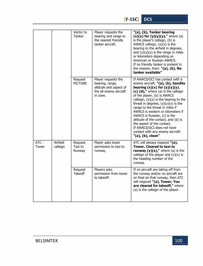
[F-15C] DCS
BELSIMTEK 100
Vector to Tanker
Player requests the bearing and range to the nearest friendly tanker aircraft.
"(a), (b), Tanker bearing (x)(x) for (y)(y)(y)," where (a) is the player's callsign, (b) is AWACS callsign, (x)(x) is the bearing to the airfield in degrees, and (y)(y)(y) is the range in miles or kilometers depending on American or Russian AWACS. If no friendly tanker is present in the mission, then: "(a), (b), No tanker available"
Request PICTURE
Player requests the bearing, range, altitude and aspect of the all enemy aircraft in zone.
If AWACS/GCI has contact with a enemy aircraft: "(a), (b), bandits bearing (x)(x) for (y)(y)(y). (c) (d)," where (a) is the callsign of the player, (b) is AWACS callsign, (x)(x) is the bearing to the threat in degrees, (y)(y)(y) is the range to the threat in miles if AWACS is western or kilometers if AWACS is Russian, (c) is the altitude of the contact, and (d) is the aspect of the contact. If AWACS/GCI does not have contact with any enemy aircraft: "(a), (b), clean"
ATC - Tower
Airfield callsign
Request Taxi to Runway
Player asks tower permission to taxi to runway.
ATC will always respond "(a), Tower, Cleared to taxi to runway (x)(x)," where (a) is the callsign of the player and (x)(x) is the heading number of the runway.
Request Takeoff
Players asks permission from tower to takeoff.
If no aircraft are taking off from the runway and/or no aircraft are on final on that runway, then ATC will respond "(a), Tower, You are cleared for takeoff," where (a) is the callsign of the player.
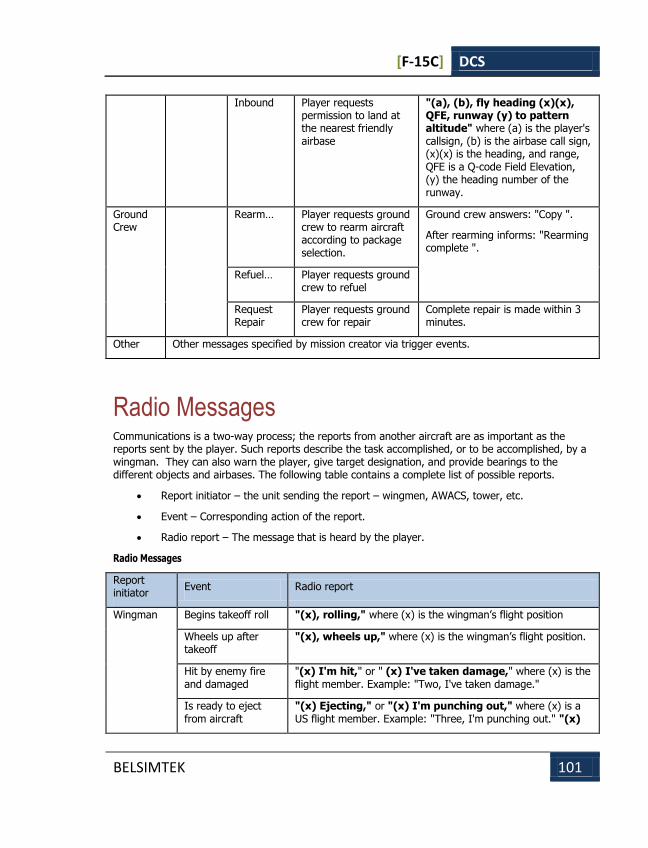
[F-15C] DCS
BELSIMTEK 101
Inbound Player requests permission to land at the nearest friendly airbase
"(a), (b), fly heading (x)(x), QFE, runway (y) to pattern altitude" where (a) is the player's callsign, (b) is the airbase call sign, (x)(x) is the heading, and range, QFE is a Q-code Field Elevation, (y) the heading number of the runway.
Ground Crew
Rearm… Player requests ground crew to rearm aircraft according to package selection.
Ground crew answers: "Copy ".
After rearming informs: "Rearming complete ".
Refuel… Player requests ground
crew to refuel
Request Repair
Player requests ground crew for repair
Complete repair is made within 3 minutes.
Other Other messages specified by mission creator via trigger events.
Radio Messages Communications is a two-way process; the reports from another aircraft are as important as the reports sent by the player. Such reports describe the task accomplished, or to be accomplished, by a wingman. They can also warn the player, give target designation, and provide bearings to the different objects and airbases. The following table contains a complete list of possible reports.
Report initiator – the unit sending the report – wingmen, AWACS, tower, etc.
Event – Corresponding action of the report.
Radio report – The message that is heard by the player.
Radio Messages
Report initiator
Event Radio report
Wingman Begins takeoff roll "(x), rolling," where (x) is the wingman’s flight position
Wheels up after takeoff
"(x), wheels up," where (x) is the wingman’s flight position.
Hit by enemy fire and damaged
"(x) I'm hit," or " (x) I've taken damage," where (x) is the flight member. Example: "Two, I've taken damage."
Is ready to eject from aircraft
"(x) Ejecting," or "(x) I'm punching out," where (x) is a US flight member. Example: "Three, I'm punching out." "(x)

[F-15C] DCS
BELSIMTEK 102
Bailing out," or "(x) I'm bailing out," where (x) is a RU flight member. Example: "Three, I'm bailing out."
Returning to base due to excessive damage
"(x) R T B," or "(x) Returning to base," where (x) is the flight member. Example: "Four, R T B."
Launched an air-to-air missile.
"Fox from (x)," if an American aircraft or "Missile away from (x)," if a Russian aircraft, where (x) is the flight member. Example: "Fox from two"
Internal gun fired "Guns, Guns from (x)," where (x) is the flight member. Example: "Guns, Guns from three."
Illuminated by enemy airborne radar
"(x), Spike, (y) o'clock," where (x) is the flight member and (y) is a number one through twelve. Example: "Two, spike three o'clock."
Illuminated by enemy ground-based radar
"(x) Mud Spike, (y) o'clock," where (x) is the flight member and (y) is a number one through twelve. Example: "Two, mud spike three o'clock."
Surface-to-Air Missile fired at wingman
"(x) Sam launch, (y) o'clock," where (x) is the flight member and (y) is a number one through twelve. Example: "Two, Sam launch three o'clock."
Air-to-Air Missile fired at wingman
"(x) Missile launch, (y) o'clock," where (x) is the flight member and (y) is a number one through twelve. Example: "Two, Missile launch three o'clock."
Visual contact on enemy aircraft
"(x) Tally bandit, (y) o'clock," where (x) is the flight member and (y) is a number one through eleven or nose. Example: "Two, Tally bandit three o'clock."
Performing defensive maneuver against threat
"(x) Engaged defensive," where (x) is the flight member. Example: "Two, Engaged defensive."
Shot down enemy aircraft
"(x) Splash one," "(x) Bandit destroyed," or "(x) Good kill, good kill," where (x) is the flight member. Example: "Two, Splash my bandit."
Destroyed enemy ground structure, ground vehicle, or ship
"(x) Target destroyed," or "(x) Good hits," where (x) is the flight member. Example: "Two, Target destroyed."
Wingman has spotted enemy aircraft and wishes to attack
"(x) Request permission to attack," where (x) is the flight member. Example: "Two, Request permission to attack."

[F-15C] DCS
BELSIMTEK 103
Iron bomb or cluster bomb released
"(x) Bombs gone," where (x) is the flight member. Example: "Two, Bombs gone."
Air-to-ground missile fired
"(x) Missile away," where (x) is the flight member. Example: "Two, Missile away."
Air-to-ground, unguided rockets fired
"(x) Rockets gone," where (x) is the flight member. Example: "Two, Rockets gone."
Flying to attack target after passing IP
"(x) Running in" or "(x) In hot," where (x) is the flight member. Example: "Two, Running in."
Enemy aircraft detected on radar
"(a) Contact bearing (x)(x) for (y)(y)(y)" where (a) is the flight member, (x) is the bearing in degrees and (y) in the range in miles for US aircraft and kilometers for Russian aircraft. Example: "Three, Contact bearing one eight for zero five zero."
Has reached fuel state in which aircraft must return to base or risk running out of fuel
"(x) Bingo fuel," where (x) is a US flight member. Example: "Two, Bingo fuel." "(x) Low fuel," where (x) is a RU flight member. Example: "Two, Low fuel."
No remaining weapons on wingman's aircraft.
"(x) Winchester," when US wingman and (x) is flight member. "(x) Out of weapons," when Russian wingman and (x) is flight member.
Enemy aircraft is behind player's aircraft.
"Lead, check six"
Player's aircraft is about to explode or crash.
"Lead, bail out"
Tower Player has come to a halt after landing on runway.
"(x), Tower, taxi to parking area," where (x) is the callsign of the aircraft. Example: "Hawk one one, Tower, taxi to parking area."
Player has reached approach point and has been passed over to tower control. The runway is clear for landing.
"(x), Tower, cleared to land runway (y)(y)," where (x) is the callsign of the aircraft and (y) is the two-digit runway heading of the runway the aircraft is to land on. Example: "Hawk one one, Tower. cleared to land runway nine zero."
Player has reached "(x), Tower, orbit for spacing," where (x) is the callsign of
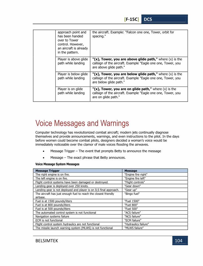
[F-15C] DCS
BELSIMTEK 104
approach point and has been handed over to Tower control. However, an aircraft is already in the pattern.
the aircraft. Example: "Falcon one one, Tower, orbit for spacing."
Player is above glide path while landing
"(x), Tower, you are above glide path," where (x) is the callsign of the aircraft. Example "Eagle one one, Tower, you are above glide path."
Player is below glide path while landing
"(x), Tower, you are below glide path," where (x) is the callsign of the aircraft. Example "Eagle one one, Tower, you are below glide path."
Player is on glide path while landing
"(x), Tower, you are on glide path," where (x) is the callsign of the aircraft. Example "Eagle one one, Tower, you are on glide path."
Voice Messages and Warnings Computer technology has revolutionized combat aircraft; modern jets continually diagnose themselves and provide announcements, warnings, and even instructions to the pilot. In the days before women could become combat pilots, designers decided a woman’s voice would be immediately noticeable over the clamor of male voices flooding the airwaves.
Message Trigger – The event that prompts Betty to announce the message
Message – The exact phrase that Betty announces.
Voice Message System Messages
Message Trigger Message
The right engine is on fire. "Engine fire right"
The left engine is on fire. "Engine fire left"
Flight control systems have been damaged or destroyed. "Flight controls"
Landing gear is deployed over 250 knots. "Gear down"
Landing gear is not deployed and player is on ILS final approach. "Gear up"
The aircraft has just enough fuel to reach the closest friendly airbase.
"Bingo fuel"
Fuel is at 1500 pounds/liters "Fuel 1500"
Fuel is at 800 pounds/liters "Fuel 800"
Fuel is at 500 pounds/liters "Fuel 500"
The automated control system is not functional "ACS failure"
Navigation systems failure "NCS failure"
ECM is not functional "ECM failure"
Flight control system hydraulics are not functional "Hydraulics failure"
The missile launch warning system (MLWS) is not functional "MLWS failure"
Radio Communications and Messages
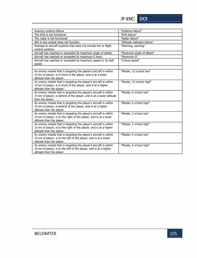
[F-15C] DCS
BELSIMTEK 105
Avionics systems failure "Systems failure"
The EOS is not functional "EOS failure"
The radar is not functional "Radar failure"
ADI in the cockpit does not function. "Attitude indicaton failure"
Damage to aircraft systems that does not include fire or flight
control systems.
"Warning, warning"
Aircraft has reached or exceeded its maximum angle of attack. "Maximum angle of attack"
Aircraft has reached or exceeded its maximum G level. "Maximum G"
Aircraft has reached or exceeded its maximum speed or its stall speed.
"Critical speed"
An enemy missile that is targeting the player's aircraft is within
15 km of player, is in front of the player, and is at a lower altitude than the player.
"Missile, 12 o'clock low"
An enemy missile that is targeting the player's aircraft is within 15 km of player, is in front of the player, and is at a higher
altitude than the player.
"Missile, 12 o'clock high"
An enemy missile that is targeting the player's aircraft is within
15 km of player, is behind of the player, and is at a lower altitude than the player.
"Missile, 6 o'clock low"
An enemy missile that is targeting the player's aircraft is within 15 km of player, is behind of the player, and is at a higher
altitude than the player.
"Missile, 6 o'clock high"
An enemy missile that is targeting the player's aircraft is within
15 km of player, is to the right of the player, and is at a lower altitude than the player.
"Missile, 3 o'clock low"
An enemy missile that is targeting the player's aircraft is within 15 km of player, is to the right of the player, and is at a higher
altitude than the player.
"Missile, 3 o'clock high"
An enemy missile that is targeting the player's aircraft is within
15 km of player, is to the left of the player, and is at a lower altitude than the player.
"Missile, 9 o'clock low"
An enemy missile that is targeting the player's aircraft is within 15 km of player, is to the left of the player, and is at a higher altitude than the player.
"Missile, 9 o'clock high"

[F-15C] DCS
BELSIMTEK 106
THEORETICAL TRAINING
THEORETICAL TRAINING
[F-15C] DCS
BELSIMTEK 107
THEORETICAL TRAINING To be successful in air combat is not an easy task. Fighter pilots of all countries practice for many years to achieve the skills necessary to get the maximum performance out of their aircraft. Though it is impossible to model every aspect of flight training, it is nevertheless important to understand some principles of combat aviation.
Indicated Air Speed and True Airspeed As a rule, when flight altitude decreases, the air density increases. The denser atmosphere contributes to a greater lift force, but the drag component increases as well. The thinner air at high altitudes reduces aircraft lift, but drag will decrease. This contributes to higher airspeeds at high altitude. An aircraft traveling at 700 km per hour possesses different flight characteristics when flying at 1,000 km per hour. The actual speed at which aircraft flies through the air mass is called the true air speed (TAS). TAS automatically compensates for air pressure and density. Related to TAS, Ground Speed (GS) is the aircraft's actual speed across the earth. It equals the TAS plus or minus the wind factor.
Most modern aircraft have airspeed indicators that take into account air density and humidity changes at different altitudes. When these changes are not taken into account, the aircraft velocity is called Indicated Air Speed (IAS). For the pilot, the IAS is the basis for defining maneuvering capabilities of an aircraft; it is usually displayed on the HUD and dash.
THE AIRSPEED INDICATOR SHOW THE AIRCRAFT’S INDICATED AIR SPEED
Velocity Vector The total velocity vector indicator is a common feature on western HUDs; it is also called the Flight Path Marker (FPM). The velocity vector indicates the actual flight direction of the aircraft, which may not correspond with where the nose of the jet is actually pointed. If you place the velocity vector on a point on the ground, eventually, the aircraft will fly directly into that point. This indicator is important tool for pilots and can be used from combat maneuvering to landing approaches. Modern, highly maneuverable aircraft like F-15C can fly at high angles-of-attack (AoA) - when the aircraft flies in one direction but the longitudinal axis is directed in another.
Angle-of-Attack (AoA) Indicator As described above, the velocity vector may not coincide with the longitudinal axis of the aircraft. The angle between the velocity vector projection and the aircraft’s longitudinal axis is termed angle-of-attack. When the pilot pulls the control stick back, he generally increases the aircraft angle-of-attack.
[F-15C] DCS
BELSIMTEK 108
If during a straight and level flight the pilot reduces the engine thrust, the aircraft will start to lose altitude. To continue the level flight, one needs to pull back on the stick and thereby increasing AoA.
AoA and IAS are connected with an aircraft’s lift characteristics. When aircraft AoA is increased up to critical value, aerodynamic lifting force also increases. Increasing indicated airspeed at a constant AoA can also contribute to lifting forces. However, induced airframe drag also increases when AoA and airspeed increase. One has to keep this in mind or the aircraft could depart controlled flight. For example, the aircraft may depart if the pilot exceeds AoA limits. Limitations are always indicated on the aircraft’s AoA indicator gauge.
ABRUPT, HIGH-G MANEUVERING AT HIGH ANGLES-OF-ATTACK MAY CAUSE THE AIRCRAFT DEPARTURE
When aircraft AoA is increased up to a critical value, the airflow becomes disrupted over the wing and the wing ceases to generate lift. Asymmetrical air-mass separation from the left and right wings can induce side movement (yaw) and stall the aircraft. The stall may happen when the pilot exceeds the allowed AoA. It is especially dangerous to get into stalls when in air combat; in a spin and out of control, you’re an easy target for the enemy.
When in a spin, the aircraft rotates about its vertical axis and constantly losing altitude. Some types of aircraft may also oscillate in pitch and roll. When in a spin, the pilot has to concentrate all his attention on recovering the aircraft. There are many methods to recover various aircraft types from a spin. As a general rule, one should reduce thrust, deflect rudder pedals in the opposite direction of the spin, and keep the flight stick pushed forward. The control devices should be kept in this position until the aircraft stops spinning and enters a controllable, nose-down pitch angle. After recovering, place the aircraft back into level flight, but be careful not to re-enter a spin. Altitude loss during a spin can reach several hundred meters.
TO RECOVERY THE AIRCRAFT FROM A SPIN: REDUCE THRUST, DEFLECT RUDDER PEDALS IN THE OPPOSITE
DIRECTION OF THE SPIN, AND PUSH THE CONTROL STICK FORWARD. LEAVE THE CONTROLS IN THIS POSITION
UNTIL THE SPIN CEASES
Turn Rate and Radius of Turn The aerodynamic lift force vector is oblique to the aircraft’s velocity vector. As long as the force of gravity is balanced by the lifting force, the aircraft maintains level flight. When the aircraft’s bank angle changes, the lift force projection on the vertical plane decreases.
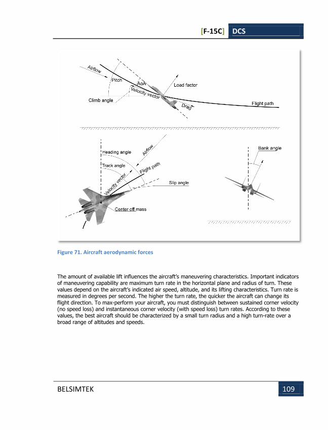
[F-15C] DCS
BELSIMTEK 109
Figure 71. Aircraft aerodynamic forces
The amount of available lift influences the aircraft’s maneuvering characteristics. Important indicators of maneuvering capability are maximum turn rate in the horizontal plane and radius of turn. These values depend on the aircraft’s indicated air speed, altitude, and its lifting characteristics. Turn rate is measured in degrees per second. The higher the turn rate, the quicker the aircraft can change its flight direction. To max-perform your aircraft, you must distinguish between sustained corner velocity (no speed loss) and instantaneous corner velocity (with speed loss) turn rates. According to these values, the best aircraft should be characterized by a small turn radius and a high turn-rate over a broad range of altitudes and speeds.
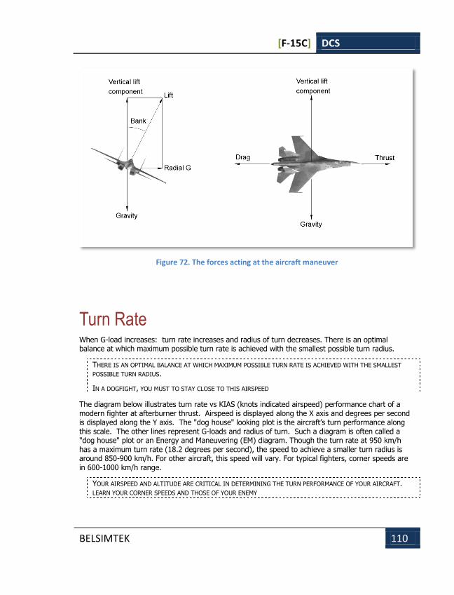
[F-15C] DCS
BELSIMTEK 110
Figure 72. The forces acting at the aircraft maneuver
Turn Rate When G-load increases: turn rate increases and radius of turn decreases. There is an optimal balance at which maximum possible turn rate is achieved with the smallest possible turn radius.
THERE IS AN OPTIMAL BALANCE AT WHICH MAXIMUM POSSIBLE TURN RATE IS ACHIEVED WITH THE SMALLEST
POSSIBLE TURN RADIUS.
IN A DOGFIGHT, YOU MUST TO STAY CLOSE TO THIS AIRSPEED
The diagram below illustrates turn rate vs KIAS (knots indicated airspeed) performance chart of a modern fighter at afterburner thrust. Airspeed is displayed along the X axis and degrees per second is displayed along the Y axis. The "dog house" looking plot is the aircraft’s turn performance along this scale. The other lines represent G-loads and radius of turn. Such a diagram is often called a "dog house" plot or an Energy and Maneuvering (EM) diagram. Though the turn rate at 950 km/h has a maximum turn rate (18.2 degrees per second), the speed to achieve a smaller turn radius is around 850-900 km/h. For other aircraft, this speed will vary. For typical fighters, corner speeds are in 600-1000 km/h range.
YOUR AIRSPEED AND ALTITUDE ARE CRITICAL IN DETERMINING THE TURN PERFORMANCE OF YOUR AIRCRAFT. LEARN YOUR CORNER SPEEDS AND THOSE OF YOUR ENEMY
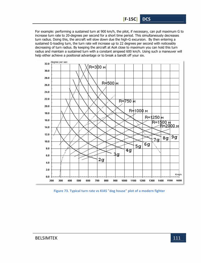
[F-15C] DCS
BELSIMTEK 111
For example: performing a sustained turn at 900 km/h, the pilot, if necessary, can pull maximum G to increase turn rate to 20-degrees per second for a short time period. This simultaneously decreases turn radius. Doing this, the aircraft will slow down due the high-G excursion. By then entering a sustained G-loading turn, the turn rate will increase up to 22 degrees per second with noticeably decreasing of turn radius. By keeping the aircraft at AoA close to maximum you can hold this turn radius and maintain a sustained turn with a constant airspeed 600 km/h. Using such a maneuver will help either achieve a positional advantage or to break a bandit off your six.
Figure 73. Typical turn rate vs KIAS "dog house" plot of a modern fighter

[F-15C] DCS
BELSIMTEK 112
Sustained and Instantaneous Turns An instantaneous turn is characterized by high turn rates and airspeed loss during maneuvering. The airspeed loss is due to the significant drag generated by the high G and AoA levels. AoA and G loading factors can often reach their maximum, allowable values in a "max-performance", instantaneous turn. Although it will slow your aircraft down, it is the fastest way to get your nose on a target. You may be in an energy-hole after doing so though.
REGULAR, INSTANTANEOUS TURNS RESULT IN SIGNIFICANT AIRSPEED LOSS
When performing a sustained turn, drag and gravity are balanced by engine thrust. The sustained turn rate of turn is lower than the instantaneous turn rate, but is achieved without airspeed loss. In theory, the aircraft can perform a steady turn until it runs out of fuel.
Energy Control In air combat, the pilot must control the aircraft’s energy state. The total energy of an aircraft can be represented as a sum of potential energy and kinetic energy. Potential energy is determined by the aircraft’s altitude; kinetic energy is determined by airspeed. Because thrust developed by the engines is limited, flying at a high AoA will cancel out the thrust. The aircraft will lose energy. To prevent this during combat, the pilot should keep his flight envelope such that he is maneuvering at the aircraft’s maximum sustained turn rate and minimizing turn radius simultaneously.
TOO MANY HARD TURNS WITH ALTITUDE LOSS LEAD TO AN AIRCRAFT WITH LITTLE ENERGY
Suppose that energy is equivalent to "money" used to "buy" maneuvers. Suppose there is a constant replenishment (while the aircraft’s engines are running). Optimal control requires rational "money" consumption for necessary maneuver purchases. Performing high-G turns causes the aircraft to lose speed and consequently the energy supply (bank) lowers. In this case you can say that the price for cheap turn rate was too high. You now have little money left in the bank and are an easy target for an enemy with a fist full of cash.
Therefore, without a critical need, you should avoid high-G maneuvers that result in speed loss. You should also try to maintain high altitude and not lose it without good reason (this is money in your energy bank). In close combat, try to fly the aircraft at speeds that maximize your sustained turn rate while minimizing your turn radius. If your airspeed reduces significantly, you have to reduce AoA by pushing the stick forward and "unloading" the aircraft. This will allow you to gain speed quickly. However, you need time this unloading carefully or you will give an enemy an easy kill.
IF YOU LOSE CONTROL OVER AIRCRAFT ENERGY MANAGEMENT, YOU WILL SOON FIND YOURSELF WITH LITTLE
AIRSPEED AND ALTITUDE

[F-15C] DCS
BELSIMTEK 113
COMBAT PPERATION BASICS
COMBAT OPERATION BASICS
[F-15C] DCS
BELSIMTEK 114
COMBAT OPERATION BASICS Modern air combat tactics have changed in revolutionary ways in less than a century. The small, propeller-driven fighters of decades ago have evolved into the modern jet fighters of today.
The primary reason why virtual pilots crash or are often killed is due to the inconsistency between a combat situation and the weapons they use. Today’s aircraft are much more powerful than their WWII era brethren. However, enemy firepower is much more accurate and lethal now, and it can engage targets at much longer ranges. In short, the battlefield has become more dangerous than it was before.
Air Combat Tactics Modern fighters like the Su-27, MiG-29 and F-15C were designed to achieve air superiority over the battlefield. Although they can carry a limited number and types of air-to-surface weapons, air combat is their priority task. During air combat, it is better to kill the enemy at long range, and only engage within visual range if necessary. With the advent of the Russian R-73 and helmet mounted sight, this is particularly true for western aircraft. For interceptors such as the Su-27 and F-15C, it is important to start an engagement with the enemy at long-range, before the enemy can bring weapons to bear. Ideally, the enemy aircraft will be damaged or destroyed and won’t be able to carry out its mission. It is often more important to deny the enemy from completing its mission that actually destroying the enemy aircraft.
Target Search Modern fighters often have powerful radars that are able to detect targets at long range. In addition to onboard radar, it is also helpful to have an airborne warning and control system (AWACS) aircraft in the air or ground early control intercept (GCI) radar stations that can monitor the airspace and vector friendly assets against enemy forces. Using AWACS and GCI, it is possible to conduct covert missions that enter enemy airspace with the onboard radar in standby mode (not emitting energy that could be detected by the enemy). If the radar is in standby, the chance of being detected by the enemy decreases (enemy aircraft can detect your radar emissions at a range twice of what you can detect them). Additionally, during a covert attack, Russian aircraft can use IRST systems that cannot be detected by radar warning systems. If an enemy aircraft is using onboard jamming systems, you can use AWACS and GCI to determine ranging information.
If an AWACS or GCI is not available, the fighter will need to use its own sensors during the mission. When there are multiple aircraft within a flight, the flight leader should order "line abreast" formation to increase the volume of air space that the flight’s radars are scanning.
Pilots must be aware that detection range depends on a target’s radar cross section (RCS). The simple rule is that the larger the RCS, the greater the range at which it can be detected by radar. RCS has no affect on non-radar sensors such as IRST. For example: an Su-27 flying at high altitude can detect a strategic bomber-class target with an RCS of 70 – 100 sq. m at distance of 130 – 180 km. A modern fighter with an RCS of 3 sq. m can only be detected at 80 – 100 km. At low altitudes, detection ranges are reduced significantly due to the side lobe feedback noise from the ground being received back into the antenna. This noise forces the radar to decrease gain levels and thereby
[F-15C] DCS
BELSIMTEK 115
lowering its sensitivity. For example: an Su-27 flying at 200 m has a maximum detection distance of only 35 – 40 km against high targets aspect and 20 – 25 km against low targets aspect. This same restriction applies to detecting targets at lower altitudes than your own. In such a "look down" situation, the radar sensitivity is reduced due to the excessive ground clutter. The following conclusion can be made: –long-range air combat is severely restricted at the low altitudes and weapon and radar performance will be greatly reduced. The best engagement profile is to be flying above 3,000 m with the target slightly above you at a high aspect angle.
Beyond Visual Range (BVR) Combat You have detected an enemy aircraft and you are ready to attack it with medium or long range missiles. However, the enemy has the same intentions and is equipped with missiles similar to your own. In such a situation, victory is not obvious and depends greatly on several factors such as maintaining a stable target lock and the missile’s maximum launch range. When such factors are equal, the adversaries have an equal chance of victory. In order to gain an advantage, one must use BVR tactics to gain the upper hand.
The most common tactic is called the tactical turn away. The maneuver calls for launching a missile at long-range and then turning away from the target while keeping the target within the outer gimbal limits of the radar. While maintaining radar lock on the target and supporting the launched missile, the rate of closure with the target decreases. With a reduced closure rate, the enemy’s fire control computer may delay allowable launch or at least delay the enemy pilot from launching until he reaches Rpi. When both you and the enemy launch at the same time, a tactical turn away will cause the enemy’s missile to fly a less efficient, longer flight path and use more energy. If the enemy missile still manages to reach you, a high-G maneuver should easily defeat a missile low on energy.
Maneuvers If both you and the enemy manage to survive the BVR joust and enter within visual range (WVR), the classic dogfight will often ensue.
THE CLOSE AIR COMBAT IS NOT A CHESS GAME. A PILOT DOES NOT THINK: "HE IS DOING A LOOP AND I MUST DO
A TURN". THIS IS A FLEXIBLE, DYNAMIC AND CONSTANTLY CHANGING ENVIROMENT. A PILOT ESTIMATES WHERE
HE SHOULD BE IN ORDER TO USE HIS WEAPONS AND BRING HIS WEAPONS TO BEAR BEFORE THE ENEMY
Combat Turnaround The combat turnaround is one of the most basic maneuvers. The pilot performs a 180–degree turn while simultaneously performing a climb. This accumulates energy for the following maneuver. This maneuver should be done at MIL power, or even full AB thrust, in order to accomplish it quickly and without significant loss of airspeed.
If you are in the offensive position with a speed advantage and the enemy performs a defensive maneuver (such as a break), then you can perform a "Hi Yo-Yo" maneuver that will retain your offensive position and energy.
"Hi Yo-Yo" Maneuver The "Hi Yo-Yo" maneuver is similar to a combat turnaround. First execute a steep climb perpendicular to the target’s flight path. During this maneuver, it is important that you do not lose sight of the enemy; always know his location. This maneuver should be accomplished a bit behind and higher

[F-15C] DCS
BELSIMTEK 116
than the target. As you climb past the target, roll back into the same maneuver plane as the target. This sets you up with an attack with both a positional and energy advantage. Generally speaking, the execution of a series of small "Hi Yo-Yo" maneuvers is better than performing a single, large maneuver. Be careful of the enemy pilot that recognizes this maneuver and reverses back into you; this can then form into a "scissors" dog fight.
Scissors Defensive Maneuver If the enemy approaches you from behind and is about to fire, you must take immediate action. One of the most effective maneuvers that can quickly turn the attacker into the defender is called the "scissors". The essence of the maneuver is simple; use the speed advantage of the enemy to turn inside him and force him into a series of single-circle merges. The one with the higher roll rate and slow speed maneuvering capability will get behind the other.
Gun Employment in Air Combat Using the gun of a moving aircraft against another maneuvering aircraft is a not trivial task. First, the number of cannon shells onboard and effective gun range are quite limited. During a fight, an enemy is constantly maneuvering and it is very difficult to estimate the point at which the pilot should fire. World War II pilots had to calculate this point "by sight" and estimate when the fired shells and the enemy aircraft would intersect. As a result, it was very difficult for a pilot to maneuver in two planes and quickly calculate the lead angle.
Figure 74. Gun use during air combat
Meanwhile, the attacking aircraft is also constantly moving and flies along a curvilinear trajectory. From inside the aircraft, shell trajectory appears to be "bent", when in fact they are flying straight. If everything goes according to plan, the pilot is aiming with proper lead, opens fire and watches the "bent" line and corrects fire.
Based on the above, we can conclude that range to target is one of the most important factors in hitting another aircraft with the gun. The farther the target is, the longer the shell flies, and the more
[F-15C] DCS
BELSIMTEK 117
it is affected by the drag and gravity. Therefore, the pilot should consider greater lead angle for larger cannon shells. Due to this challenge, many pilots of World War I and II would not open fire until they were in range to see the face of the enemy pilot. This ensured a minimal effect of drag and gravity on their shells. The lower the range to the target is, the greater the hit possibility. The correct lead-angle becomes more and more difficult as range to target grows.
In the modern aircraft, pilots are now capable of determining correct lead points due to weapon control systems that continuously calculate the lead aiming point; however, they do have their limits. In order to calculate a lead point it is necessary to know the range to target; this information is supplied to the WCS by a radar or laser range-finder. Based on the aircraft and target movement parameters, the lead point is calculated and the gun pipper is drawn on the aircraft HUD. The pilot then flies the aircraft to place the pipper on the target and fire the gun. The gun pippers of Russian and American aircraft looks different, but their function is essentially the same.
In situations where it is impossible to get range data on the target due to radar malfunction or ECM, other gun aiming systems are available. Such a system is the "funnel" that indicates the ballistic flight path of cannon rounds. The center-area of the funnel is the shell flight path; the two outside lines denote target wingspan (also called "target base").
To aim with the funnel, you must place the target within the funnel and have the target’s wingtips touch the sides of the funnel. If done properly against a fighter-sized target, the cannon shells will impact the target. The funnel is not as accurate against high aspects targets because of the angular rotation values. Similarly, it is difficult to aim at targets that are maneuvering with variable angular velocity and/or rapidly changing their direction of flight.
A gun attack assumes a relatively smooth approach to the target, a sustained firing position and opening fire. On the other hand, a shot opportunity is available with a snap-shot when the enemy aircraft, possibly unexpectedly, appears in front of you and in guns range. It is necessary to seize this moment and hit the target while it is "caught" in the gun pipper.
When maneuvering at high-G loads, the gun pipper is usually along the lower portion of the HUD and it is very difficult to aim in such a situation. In such a case, maneuver with lead pursuit inside the target’s maneuver plane, and for a brief moment, decrease your G-loading. Squeeze a gun burst shortly before the target flies through the gun pipper and allow the gun burst to walk through the target.
Accuracy with the gun takes a great deal of skill, and above all, lots of practice. Try to stay in the same maneuver plane as your target as this will allow a steady tracking shot. There are two maneuver vectors. There is the longitudinal vector and the lift vector. Though a good marksman can consistently hit targets in both planes and combination of them, a target not maneuvering or maneuvering in only a single plane can be an easy target. Avoid doing so or you may soon be under someone else’s gun pipper.
To best match your target’s maneuver plane, try to match the target’s angle of bank and pitch. You can achieve a high hit percentage by maneuvering behind the enemy and adapting yourself to his maneuver. If you blend this with the predicted target trajectory, then the target will soon be in your sights.

[F-15C] DCS
BELSIMTEK 118
Air-to-Air Missile Tactics Good combat pilots know which missiles are best used for within visual range combat and which to use for beyond visual range. The employment of these missile systems is described in detail in the corresponding chapter, as are reference to different aircraft types.
Before a radar-guided missile can be launched, it is generally required to establish a radar lock and select the best missile according to the targets distance. For a Russian aircraft, missile launch is impossible until the "Launch Authorized" WCS command is given. When it is given, the WCS calculates if it is safe to launch the missile and if the missile has a high probability of a kill. In an emergency though, this authorization consent can be overridden. The F-15C on the other hand can launch missiles at any time. However, to give the pilot cues as to the probability of kill, there are three indicators: minimum permitted launch range (Rmin), maximum permitted launch range to maneuvering target (Rtr), and the maximum permitted launch range to non-maneuvering target (Rpi).
Launching a missile at long ranges decreases hit probability; the shorter the distance the missile has to fly to the target, the higher the hit possibility.
When within visual range of enemies, the pilot should strive for situational awareness and never lose track of what is going on around him. Never lose sight of the enemy, especially when you are on the defensive. Remember that threat warning systems do not alert you to the launch of an infrared-guided missile. That is why you can suddenly get a missile up your tail pipe without warning. As such, it is often best to use pre-emptive flares when entering a fight with aircraft loaded with infrared weapons. The only way you will detect the launch of an infrared system is with your own eyes or a wingman’s warning. In the WVR arena, keep your eyes out of the cockpit and look for the tell-tail sign of a missile trail heading your way. Also remember that your jet engines are a magnet for infrared seekers. To reduce your vulnerability to infrared seekers, keep out of afterburner if you can. During combat, try to only use AB when the enemy cannot take a shot at you. If an infrared-guided missile is launched on you, reduce engines to mil power, pump out flares, and perform a high-G break when the missile nears. For best results, dispense 2-3 flares every second until the missile has missed.
Missile Breakaway Missiles are a deadly and difficult threat to defeat. They are much faster than aircraft, they can sustain three to four times greater G-loads, and are quite difficult to visually acquire. Successful defense against a missile depends on many factors such as timely detection, distance to missile, missile type, air speed, and altitude. Depending on circumstances, you can use countermeasures and perform anti-missile maneuvers.
Fortunately (for the target aircraft), missiles are affected by the same physics laws as aircraft. When missile motor burn is complete, it flies only on the energy it built up during its acceleration. When the target aircraft maneuvers, the missile also has to maneuver and this energy expenditure significantly reduces the missile’s speed. As speed decreases, missile control surfaces become less effective and will eventually be unable to generate the required G to intercept the target.
[F-15C] DCS
BELSIMTEK 119
Launch Warning The launch warning of a radar-guided missile comes from the RWS. In some circumstances, a wingman may observe a missile launch and make a warning call over the flight radio. This information is especially valuable if an infrared-guided missile is launched at you because your RWS will not detect such a launch. In this case, a wingman message may be the only warning given. In any case, you should try to visually detect the tell-tail smoke trail from a missile to time your defensive maneuver properly. When you are over enemy territory, you should be constantly scanning the airspace around you to detect missile motor smoke. Note that some missiles, like the AIM-120, use a smokeless motor.
Remember that there will be no smoke trail once the motor has burned out. As such, early detection is crucial. Long and medium range air-to-air missiles use a "loft" flight trajectory when launched at long range. This gives them an arcing flight path that extends their range. Be especially attentive to arcing trails on the horizon.
Knowledge is Power Your primary weapon is the knowledge of enemy weapon systems and how to use their characteristics to better your situation. For example: a particular air-to-air medium- range missile has a nominal range of 30 km at an altitude of 5,000 m. On your radar and RWS you detect an enemy aircraft 30 km and you hear the launch warning. You understand that a missile has been launched from maximum range for this altitude, and because of this, you may be able to escape it. You turn 180 degrees, select afterburner and fly away from the oncoming missile. Your success depends on how fast you can turn at maximum G (the aircraft can accelerate to 9 g, a fully loaded one – 5 g) and how fast you accelerate after the turn. If you received a launch warning early enough, you have a good chance of escaping the missile. If you detected the missile too late, or the enemy waited to launch until you were within Rpi range, this tactic may not work.
Electronic Warfare Means Electronic countermeasures (ECM) systems were primarily designed to interfere with radar systems. ECM systems are divided into two general types: noise jammers that are generally mounted on dedicated electronic warfare aircraft and self-protection deception jammers that are mounted as external pods or installed internally on tactical aircraft. Self-protection jamming is accomplished by sampling the threat radar’s signal and sending a mimic back but changed to give incorrect data to the enemy radar operator. Deception jammers are generally active only when the target aircraft is being illuminated by radar. There are several types of deception jamming that include range gate stealing, terrain bounce, velocity gate stealing, and many others.
Noise jammers on the other hand bombard an area with either broad noise jamming that covers a large range of frequencies or spot noise jamming that focuses of a smaller range. Such jamming is often used to mask a larger group of aircraft and is done preemptively. The result is that the enemy radar is unable to lock on the aircraft; it only sees the strobe of the jammer along the azimuth that the jammer is transmitting. The radar cannot deduce the range or altitude of the jammer. Sending false signal back into the antenna of the radar can create the outward appearance that the aircraft is at varying distances than it actually is.
However, as the range between the radar and the noise jammer lessens, the ratio of good to bad signal ratio allows the radar operator to overcome the noise jamming. This is commonly referred to as "burn through."
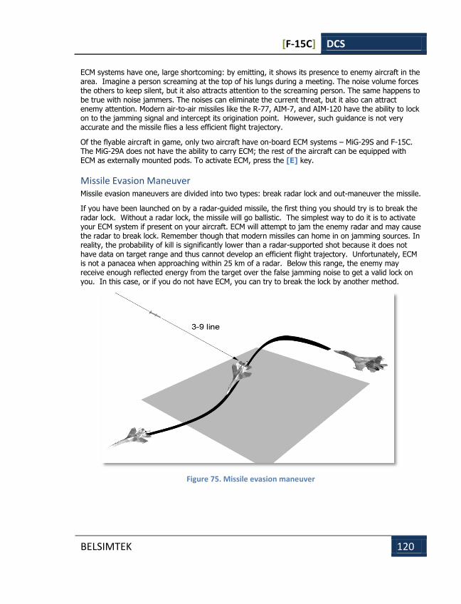
[F-15C] DCS
BELSIMTEK 120
ECM systems have one, large shortcoming: by emitting, it shows its presence to enemy aircraft in the area. Imagine a person screaming at the top of his lungs during a meeting. The noise volume forces the others to keep silent, but it also attracts attention to the screaming person. The same happens to be true with noise jammers. The noises can eliminate the current threat, but it also can attract enemy attention. Modern air-to-air missiles like the R-77, AIM-7, and AIM-120 have the ability to lock on to the jamming signal and intercept its origination point. However, such guidance is not very accurate and the missile flies a less efficient flight trajectory.
Of the flyable aircraft in game, only two aircraft have on-board ECM systems – MiG-29S and F-15C. The MiG-29A does not have the ability to carry ECM; the rest of the aircraft can be equipped with ECM as externally mounted pods. To activate ECM, press the [E] key.
Missile Evasion Maneuver Missile evasion maneuvers are divided into two types: break radar lock and out-maneuver the missile.
If you have been launched on by a radar-guided missile, the first thing you should try is to break the radar lock. Without a radar lock, the missile will go ballistic. The simplest way to do it is to activate your ECM system if present on your aircraft. ECM will attempt to jam the enemy radar and may cause the radar to break lock. Remember though that modern missiles can home in on jamming sources. In reality, the probability of kill is significantly lower than a radar-supported shot because it does not have data on target range and thus cannot develop an efficient flight trajectory. Unfortunately, ECM is not a panacea when approaching within 25 km of a radar. Below this range, the enemy may receive enough reflected energy from the target over the false jamming noise to get a valid lock on you. In this case, or if you do not have ECM, you can try to break the lock by another method.
Figure 75. Missile evasion maneuver
[F-15C] DCS
BELSIMTEK 121
Modern pulse-Doppler radars, with all their advantages, have a serious shortcoming – they have difficulties tracking targets that are flying perpendicular to their flight path. If the target is also at a lower altitude and forcing the radar into a look-down situation, radar tracking can be very problematic. This zone is termed the look down clutter notch. Accordingly, to break a radar lock one should place the enemy radar at 3 or 9 o’clock and get below the enemy radar’s altitude.
THE OPTIMAL MISSILE EVASION MANEUVER IS TO BREAK THE ENEMY RADAR LOCK BY DESCENDING IN A STEEP
SPIRAL UNTIL THE ENEMY IS LOCATED ON YOUR 3–9 LINE WHILE ACTIVATING ECM AND DISPENSING CHAFF
If the radar lock warning on your RWS ceases, it means that the radar has lost lock and is unable to support the missile. At this point you can either switch to the offensive or use terrain masking and other means to prevent the radar from re-acquiring you.
If the missile has a radar seeker though, the missile may continue the intercept.
It should be noted that this method only applies to airborne radars; SAM radars work differently and have the ability to track targets "in the beam" (perpendicular to the radars line of sight), but with some limitations.
Another set of maneuvers is designed to out-maneuver the missile. Modern missiles calculate the intercept impact point in relation to the target. This means that every time the target changes direction the missile also has to change its direction. The missile will attempt to fly a leading flight path in order to hit its target. This navigation method is termed proportional navigation (Pro Nav). If you see a missile on a constant bearing relatively to you, i.e. its visible position on your canopy does not change, this is a sure sign that the missile is tracking you towards its calculated intercept point. In such a situation, you need to take defensive action like activating ECM or dispensing chaff and flares. If the missile then starts to lag behind you, it means that the missile has probably lost lock or has been decoyed by a countermeasure.
Missiles, like aircraft, require energy to perform maneuvers and each maneuver depletes energy. Both you and a missile will lose greater speed and energy as you increase the G-loading of a maneuver. The more aggressive you are maneuvering, the more G-loading will be required of the missile to correct its intercept flight trajectory.
There are some additional items to keep in mind. The lower the altitude is; the greater the air density will be. Accordingly, the missile will lose speed and range much quicker when flying at lower altitudes. When a missile is inbound, fly a perpendicular course in relation to the missile’s flight path and dispense the chaff and flares. During this maneuver, try to stay near your aircraft’s instantaneous corner velocity. If the missile continues to track, you will need to perform a "last ditch" maneuver. When the missile is approximately 1 – 2 km from you (depending on missile speed), perform a nose-low maximum-G break turn into the flight path of the missile. For this to work, a couple factors have to be in your favor. First – the missile should be low on energy and unable to generate a high-G maneuver. Second – the missile seeker, as any mechanical device, has a limited speed at which is can gimbal and finite a angle at which it can track targets. If you provide a radical enough change in course, the seeker may be unable to track your aircraft.
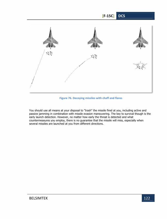
[F-15C] DCS
BELSIMTEK 122
Figure 76. Decoying missiles with chaff and flares
You should use all means at your disposal to "trash" the missile fired at you, including active and passive jamming in combination with missile evasion maneuvering. The key to survival though is the early launch detection. However, no matter how early the threat is detected and what countermeasures you employ, there is no guarantee that the missile will miss, especially when several missiles are launched at you from different directions.

[F-15C] DCS
BELSIMTEK 123
F-15C FLIGHT DYNAMICS
F-15C FLIGHT DYNAMICS
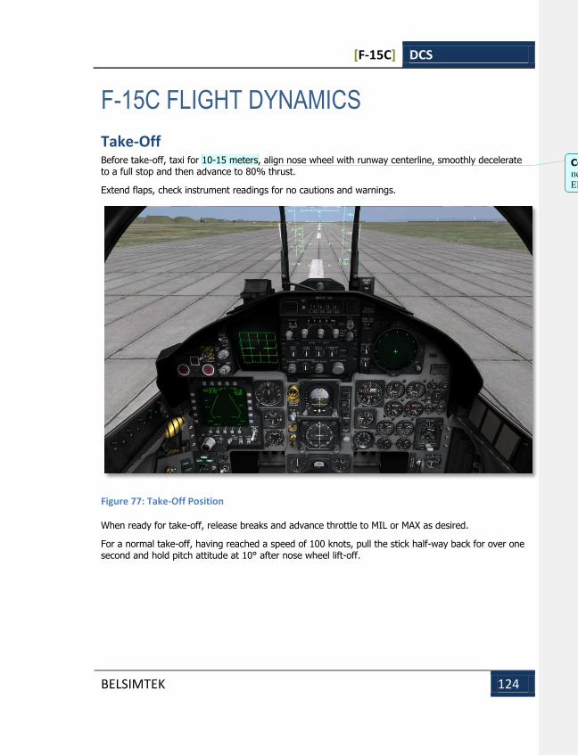
[F-15C] DCS
BELSIMTEK 124
F-15C FLIGHT DYNAMICS
Take-Off Before take-off, taxi for 10-15 meters, align nose wheel with runway centerline, smoothly decelerate to a full stop and then advance to 80% thrust.
Extend flaps, check instrument readings for no cautions and warnings.
Figure 77: Take-Off Position
When ready for take-off, release breaks and advance throttle to MIL or MAX as desired.
For a normal take-off, having reached a speed of 100 knots, pull the stick half-way back for over one second and hold pitch attitude at 10° after nose wheel lift-off.
Comment [EB6]: Может стоит подумать о переводе измерений на западные стандарты для
EN версии (впрочем может и для RU)?
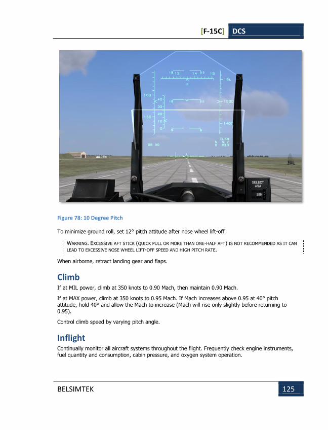
[F-15C] DCS
BELSIMTEK 125
Figure 78: 10 Degree Pitch
To minimize ground roll, set 12° pitch attitude after nose wheel lift-off.
WARNING. EXCESSIVE AFT STICK (QUICK PULL OR MORE THAN ONE-HALF AFT) IS NOT RECOMMENDED AS IT CAN
LEAD TO EXCESSIVE NOSE WHEEL LIFT-OFF SPEED AND HIGH PITCH RATE.
When airborne, retract landing gear and flaps.
Climb If at MIL power, climb at 350 knots to 0.90 Mach, then maintain 0.90 Mach.
If at MAX power, climb at 350 knots to 0.95 Mach. If Mach increases above 0.95 at 40° pitch attitude, hold 40° and allow the Mach to increase (Mach will rise only slightly before returning to 0.95).
Control climb speed by varying pitch angle.
Inflight Continually monitor all aircraft systems throughout the flight. Frequently check engine instruments, fuel quantity and consumption, cabin pressure, and oxygen system operation.
[F-15C] DCS
BELSIMTEK 126
12 units AOA may be used for maximum range and 14,5 units AOA may be used for maximum endurance for all operating altitudes.
Approach The recommended holding airspeed is 250 knots.
Normally, during descent, after the power is set at approximately 72%, lower the nose to approximately -10° and allow airspeed to increase to 300 knots. To maintain descent rate and prevent growth of descent rate use the speed brake.
Approaching the final approach fix, slow to 200-250 knots and extend landing gear and flaps.
During the final approach phase, a minimum airspeed of 180 knots is desired. A higher airspeed may be required for heavy-weight situations.
Go Around When a go-around decision is taken, advance power to MIL or MAX. Gradually stop the descent and retract the landing gear. Having reached a speed of 200-250 knots, begin to climb and retract flaps.
Landing On final approach, set on-speed for 20-22 units AOA. At the flare point, smoothly retard the throttles to IDLE and reduce rate of descent so as to finish the flare at 0.75 - 1.0 meter above ground. At 0.75 - 1.0 meter above ground, take an attitude for a cushioned landing on the two main wheels.
Raising nose too high up to 22 units AOA in the flare may cause a hard landing and engine ground contact. After touchdown, maintain directional control by pedals. Raise the nose to approximately 13º pitch attitude to achieve aerodynamic braking.
Aerobraking is highly effective at airspeeds above 90 knots. Flaps should remain down as they also provide increased aerodynamic drag.
When airspeed is reduced below 90 knots, smoothly touch down with the nose wheel and if necessary use normal braking.
WARNING. LIMIT PITCH ATTITUDE TO 15º TO AVOID DRAGGING THE TAIL.
MANEUVERABILITY OF THE F-15C EAGLE
Basic Concept of Aircraft Maneuverability Aircraft maneuverability is aircraft capability to quickly change its spatial attitude: airspeed, altitude, and flight direction. In other words, it is the aircraft capability to change the numeric value and direction of its airspeed vector.
The aircraft’s maneuverability is employed by the fighter pilot in combat to execute individual and combined maneuvers in an effort to gain position advantage.
[F-15C] DCS
BELSIMTEK 127
Maneuverability is one of the most important characteristics of a combat aircraft. It allows the pilot to win in air combat, penetrate air defenses of the enemy, attack surface targets, form, reform, and break flight formations, reach designated destinations at required times, etc.
Maneuverability is crucial for the tactical fighter aircraft engaged in combat against enemy fighter aircarft. Attaining a dominant tactical position over the enemy, the target can be shot down with one or two missiles or cannon fire. Vice versa, if the enemy gain a dominant position (for example behind the friendly fighter), no amount of missiles or gun rounds will help.
High maneuverability also allows the aircraft to successfully break off air combat and disengage from the enemy.
Envelop of Altitudes and Airspeeds Only a graphical representation of the aircraft’s full envelope of operating altitudes and airspeeds can provide a comprehensive idea of its speed-and-altitude characteristics.
Envelope Boundaries The range of airspeeds and altitudes where horizontal flight is possible is limited on the left by the minimum airspeed, at the top by the ceiling, and on the right by the maximum possible or maximum allowable speed and is called the level flight envelope.
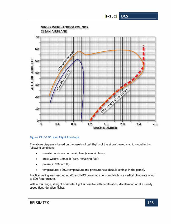
[F-15C] DCS
BELSIMTEK 128
Figure 79: F-15C Level Flight Envelope
The above diagram is based on the results of test flights of the aircraft aerodynamic model in the following conditions:
no external stores on the airplane (clean airplane);
gross weight: 38000 lb (68% remaining fuel);
pressure: 760 mm Hg;
temperature: +20C (temperature and pressure have default settings in the game).
Practical ceiling was reached at MIL and MAX power at a constant Mach in a vertical climb rate of up to 500 ft per minute.
Within this range, straight horizontal flight is possible with acceleration, deceleration or at a steady speed (long-duration flight).
[F-15C] DCS
BELSIMTEK 129
Above the ceiling and to the right of the maximum speed, horizontal flight is possible within allowable speed, but only under deceleration (short-duration flight).
To the left of the minimum speed, flight is not allowed for safety reasons, but in general is possible in the range of allowable AOA with an increased likelihood of stall.
The maximum speeds developed by the model, like those of a real aircraft, are somewhat higher than the limits imposed by design.
Flight at Stratospheric Altitudes Flight at stratospheric altitudes requires special considerations.
Due to a lower air density, higher airspeed and higher Mach number, the natural aerodynamic damping of aircraft vibrations is weaker. Any perturbations (such as a wind gust, jettison of stores, abrupt control inputs, etc.) produces weak-decaying vibrations that are distracting for the pilot (i.e. increase the tension factor) and hinder aiming in a combat situation. For this reason, at a high altitude the aircraft must be controlled with small and smooth movements of the stick. Use of the Control Augmentation System (automatic damping system, CAS) is highly recommended.
Flight at Static Ceiling Altitudes At the subsonic ceiling, the aircraft is always at the minimum drag airspeed. The reserve of kinetic energy is small, so any aft or forward movement of the stick results in a decrease of flight altitude.
At the supersonic ceiling, the reserve of kinetic energy is very large, so the aircraft can climb further without a notable loss of airspeed.
Unlike subsonic, the supersonic ceiling is not physically felt by the pilot as the aircraft easily gains more altitude, while a slow airspeed reduction is not identified immediately.
Other characteristics of flight at stratospheric altitudes are less room for varying the thrust due to increased idle rotations, difficulties with terrain recognition and visual gauging of altitude and distance to airborne targets, limited maneuverability, high target approach speeds in case of a head-on situation.
Lateral and Directional Control Characteristics The F-15C Eagle features an electronic control augmentation system (CAS) and a number of hydro-mechanical control devices designed to enhance flight control and response in all control axes (pitch, roll, yaw).
The normal mode of operation of the flight control system includes YAW and ROLL CAS ON and ROLL RATIO AUTO. The aileron/rudder interconnect (ARI) automatically coordinates the appropriate amount of rudder for lateral stick inputs.
At angles of attack (AOA) below approximately 30 cockpit units, lateral stick input provides the fastest and most controllable roll rate.
Above approximately 30 CPU, the rudder pedals provide the fastest and most controllable roll rate. Combined lateral stick and rudder pedal inputs generally result in a slower, less controllable roll performance due to adverse yaw generated by ailerons and differential stabilizers.
[F-15C] DCS
BELSIMTEK 130
Maximum available roll rates decrease rapidly as AOA increases above 35 CPU. In some cases roll input may be unresponsive unless AOA is reduced.
Lateral stick forces are light and initial roll acceleration is high, particularly during low altitude, high speed subsonic flight. This tendency is greatest with negative or high positive g loads and above 500 KCAS or Mach 1.4.
Special attention should be paid to rolling maneuvers below 30 CPU. To create favorable conditions for the control system, pilot should maneuver in one axis at a time, either roll to the desired bank angle and then pull, or pull to the desired AOA and then roll. Forward stick inputs during lateral stick may lead to autorolls.
After applying lateral stick or rudder pedal at high AOA, it is normal for the aircraft to pause briefly before it starts to roll. Abrupt, uncommanded stops in roll rate or abrupt roll reversals are not normal and should be considered a sign of impending departure.
Slow Speed Flight The aircraft exhibits no unusual slow speed flight characteristics. The handling qualities remain acceptable up to the point where there is insufficient airflow over the controls and wings to provide control power or lift. In many cases at very low speed full aft stick and/or a pegged vertical velocity may be the only sign(s) of a low energy 1-g stalled condition.
A recommended minimum airspeed of 300 KCAS will provide adequate handling qualities at low altitude.
High AOA Horizontal Flight Light buffet begins at approximately 18 CPU and increases in intensity to 23 CPU. Externals stores decrease buffet onset AOA and increase the buffet level.
Some wing rock and yaw oscillation occurs above 30 CPU. The magnitude of these oscillations varies with AOA and the amount of time spent at the AOA. Yaw and roll oscillations up to ±10º of sideslip and ±45º of bank are typical, however, even larger oscillations can occur (±90º of bank) if the wing rock is given enough time (cycles) to develop. This is accentuated in the centerline tank configuration. Required aft stick force increases with increasing AOA. With full aft stick AOA stabilizes at 45 CPU or above.
As AOA increases above 30 CPU, lateral stick becomes significantly less effective in generating roll. As AOA continues to increase above 35 CPU, lateral stick becomes ineffective. With a full aft stick, the aircraft can be controlled for roll only by rudder pedals.
The vertical velocity indicator is normally pegged in a descent. Recovery from a stall is immediate when the stick is moved forward. Any undesired roll and yaw motions should be stopped with opposite rudder pedal.
Tailslide Tailslide is a maneuver in which the aircraft intentionally or unintentionally runs out of airspeed and starts sinking while in an extremely nose high pitch attitude. As the aircraft runs out of airspeed, it may slide backward for a short period followed by either pitching forward, backward or sideways during the recovery. The CAS may fall off line during this maneuver due to yaw rate or AOA probe
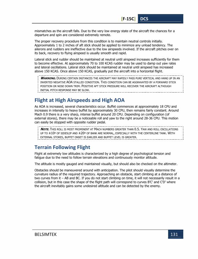
[F-15C] DCS
BELSIMTEK 131
mismatches as the aircraft falls. Due to the very low energy state of the aircraft the chances for a departure and spin are considered extremely remote.
The proper recovery procedure from this condition is to maintain neutral controls initially. Approximately 1 to 2 inches of aft stick should be applied to minimize any unload tendency. The ailerons and rudders are ineffective due to the low airspeeds involved. If the aircraft pitches over on its back, recovery to flying airspeed is usually smooth and rapid.
Lateral stick and rudder should be maintained at neutral until airspeed increases sufficiently for them to become effective. At approximately 70 to 100 KCAS rudder may be used to damp out yaw rates and lateral oscillations. Lateral stick should be maintained at neutral until airspeed has increased above 150 KCAS. Once above 150 KCAS, gradually put the aircraft into a horizontal flight.
WARNING. DURING CERTAIN INSTANCES THE AIRCRAFT MAY RAPIDLY PASS PURE VERTICAL AND HANG UP IN AN
INVERTED NEGATIVE AOA STALLED CONDITION. THIS CONDITION CAN BE AGGRAVATED BY A FORWARD STICK
POSITION OR NOSE DOWN TRIM. POSITIVE AFT STICK PRESSURE WILL RECOVER THE AIRCRAFT ALTHOUGH
INITIAL PITCH RESPONSE MAY BE SLOW.
Flight at High Airspeeds and High AOA As AOA is increased, several characteristics occur. Buffet commences at approximately 18 CPU and increases in intensity to heavy buffet by approximately 30 CPU, then remains fairly constant. Around Mach 0.9 there is a very sharp, intense buffet around 20 CPU. Depending on configuration (of external stores), there may be a noticeable roll and yaw to the right around 28-36 CPU. This motion can easily be stopped with opposite rudder pedal.
NOTE. THIS ROLL IS MOST PROMINENT AT MACH NUMBERS GREATER THAN 0.5. YAW AND ROLL OSCILLATIONS
UP TO ±10º OF SIDESLIP AND ±20º OF BANK ARE NORMAL, ESPECIALLY WITH THE CENTERLINE TANK. WITH
EXTERNAL STORES, BUFFET ONSET IS EARLIER AND BUFFET LEVEL IS GREATER.
Terrain Following Flight Flight at extremely low altitudes is characterized by a high degree of psychological tension and fatigue due to the need to follow terrain elevations and continuously monitor altitude.
The altitude is mostly gauged and maintained visually, but should also be checked on the altimeter.
Obstacles should be maneuvered around with anticipation. The pilot should visually determine the curvature radius of the required trajectory. Approaching an obstacle, start climbing at a distance of two curves from it – AB and BC. If you do not start climbing on time, it will not necessarily result in a collision, but in this case the shape of the flight path will correspond to curves B’C’ and C’D’ where the aircraft inevitably gains some undesired altitude and can be detected by the enemy.
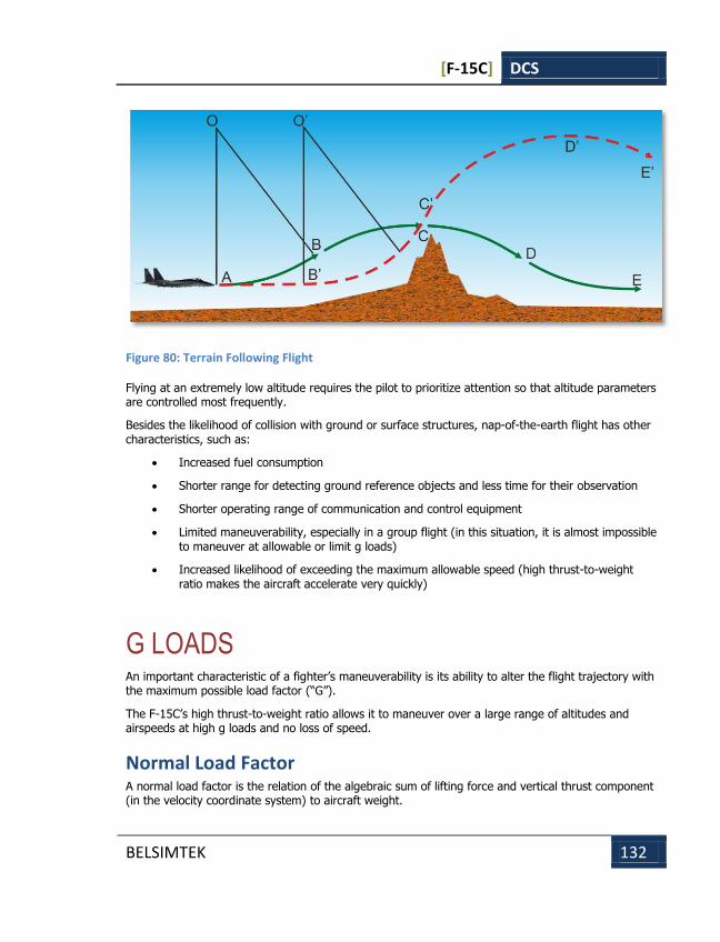
[F-15C] DCS
BELSIMTEK 132
Figure 80: Terrain Following Flight
Flying at an extremely low altitude requires the pilot to prioritize attention so that altitude parameters are controlled most frequently.
Besides the likelihood of collision with ground or surface structures, nap-of-the-earth flight has other characteristics, such as:
Increased fuel consumption
Shorter range for detecting ground reference objects and less time for their observation
Shorter operating range of communication and control equipment
Limited maneuverability, especially in a group flight (in this situation, it is almost impossible to maneuver at allowable or limit g loads)
Increased likelihood of exceeding the maximum allowable speed (high thrust-to-weight ratio makes the aircraft accelerate very quickly)
G LOADS An important characteristic of a fighter’s maneuverability is its ability to alter the flight trajectory with the maximum possible load factor (“G”).
The F-15C’s high thrust-to-weight ratio allows it to maneuver over a large range of altitudes and airspeeds at high g loads and no loss of speed.
Normal Load Factor A normal load factor is the relation of the algebraic sum of lifting force and vertical thrust component (in the velocity coordinate system) to aircraft weight.
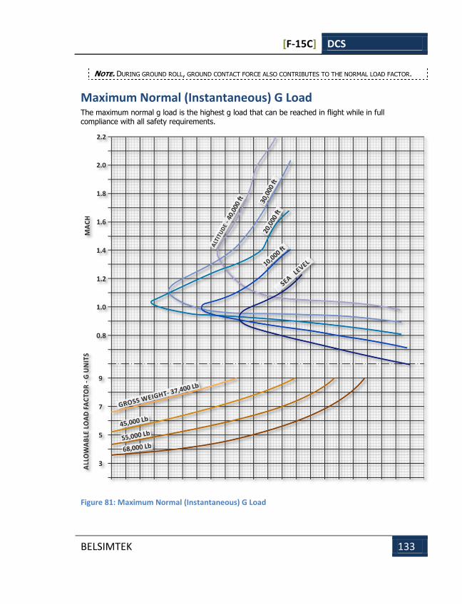
[F-15C] DCS
BELSIMTEK 133
NOTE. DURING GROUND ROLL, GROUND CONTACT FORCE ALSO CONTRIBUTES TO THE NORMAL LOAD FACTOR.
Maximum Normal (Instantaneous) G Load The maximum normal g load is the highest g load that can be reached in flight while in full compliance with all safety requirements.
Figure 81: Maximum Normal (Instantaneous) G Load
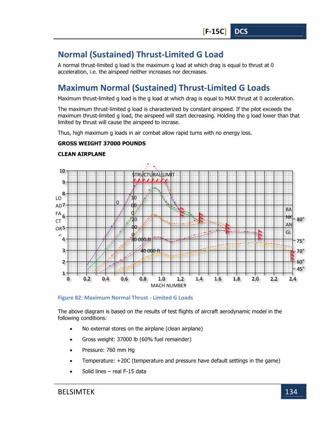
[F-15C] DCS
BELSIMTEK 134
Normal (Sustained) Thrust-Limited G Load A normal thrust-limited g load is the maximum g load at which drag is equal to thrust at 0 acceleration, i.e. the airspeed neither increases nor decreases.
Maximum Normal (Sustained) Thrust-Limited G Loads Maximum thrust-limited g load is the g load at which drag is equal to MAX thrust at 0 acceleration.
The maximum thrust-limited g load is characterized by constant airspeed. If the pilot exceeds the maximum thrust-limited g load, the airspeed will start decreasing. Holding the g load lower than that limited by thrust will cause the airspeed to incrase.
Thus, high maximum g loads in air combat allow rapid turns with no energy loss.
GROSS WEIGHT 37000 POUNDS
CLEAN AIRPLANE
Figure 82: Maximum Normal Thrust - Limited G Loads
The above diagram is based on the results of test flights of aircraft aerodynamic model in the following conditions:
No external stores on the airplane (clean airplane)
Gross weight: 37000 lb (60% fuel remainder)
Pressure: 760 mm Hg
Temperature: +20C (temperature and pressure have default settings in the game)
Solid lines – real F-15 data
MACH NUMBER
BA
NK
AN
GL
E
STRUCTURAL LIMIT
0
ft
10
00
0
ft 20
00
0
ft 30 000 ft
40 000 ft
LO
AD
FA
CT
OR
- G
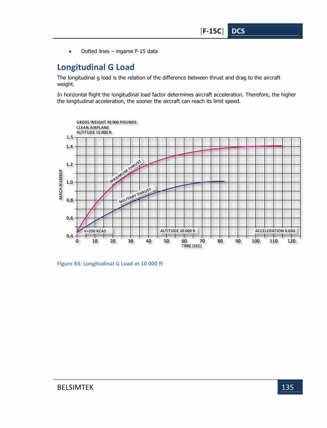
[F-15C] DCS
BELSIMTEK 135
Dotted lines – ingame F-15 data
Longitudinal G Load The longitudinal g load is the relation of the difference between thrust and drag to the aircraft weight.
In horizontal flight the longitudinal load factor determines aircraft acceleration. Therefore, the higher the longitudinal acceleration, the sooner the aircraft can reach its limit speed.
Figure 83: Longitudinal G Load at 10 000 ft

[F-15C] DCS
BELSIMTEK 136
Figure 84: Longitudinal G Load at 40 000 ft
Effects of external factors on primary maneuverability characteristics
Weight Maximum normal g load and thrust-limited normal g load change in proportion to the aircraft weight (at the constant Mach and altitude).
For any given normal g load, the longitudinal g load decreases as weight increases, but not in a simple inverse proportion, as the increase of weight also increases drag (due to the increase of trimmed AOA).
[F-15C] DCS
BELSIMTEK 137
External stores External stores impact maneuverability through their weight and through additional increase of non-induced drag.
The drag created by external stores does not affect the maximum normal g load as the latter depends solely on the available lifting force of the wing.
Thrust-limited normal g load decreases as drag increases. The higher the drag and the greater the difference between maximum thrust and drag, the less the impact of the drag from external stores on the thrust-limited g load.
The maximum longitudinal g load decreases as drag increases. The contribution of drag to the longitudinal g load becomes greater with the increase of normal load factor in a maneuver.
Atmospheric conditions As an example, consider a 1% temperature increase at a standard pressure; air density will be 1% less than the standard value, wherefrom it follows that:
For a given true airspeed (Mach number), the maximum normal g load will decrease by approximately 1%. But for a given indicated airspeed, the temperature increase will not change the load factor
The value of the thrust-limited normal g load for a given Mach will decrease as 1% temperature increase will cause the thrust to drop by approximately 2%
With the increase of air temperature, the maximum longitudinal g load will also decrease in proportion to the decrease of thrust
[F-15C] DCS
BELSIMTEK 138
F-15C CHECK LISTS F-15C CHECK LISTS
[F-15C] DCS
BELSIMTEK 139
F-15C CHECK LISTS
Start Up Step 1
Turn on navigation lights [RCtrl-L].
Step 2
Close canopy [LCtrl-C].
Step 3
Turn on left engine by setting throttles to idle and pressing [RAlt-HOME].
Step 4
Turn on right engine by setting throttles to idle and pressing [RCtrl-HOME].
Taxi and Takeoff Step 1
Once engine tachometer and temperature gauges have stabilized, increase throttle [Page Up and Page Down].
Step 2
Steer aircraft on ground using rudder controls [X and Z]. To use the wheel brakes, press [W].
Step 3
Follow tower directions to takeoff runway.
Step 4
Lower flaps [F].
Step 5
When on runway and aligned down the length of it, increase throttles to 100% [Page Up] and steer down the center of the runway [X and Z].
Step 6
At around 150 knots, gently pull back on the stick until the aircraft flies off the runway.
Step 7

[F-15C] DCS
BELSIMTEK 140
Raise landing gear [G].
Step 8
Raise flaps [F].
Navigation Step 1
Select NAV mode as indicated in the bottom right corner of the HUD [1].
Step 2
Cycle navigation waypoint [LCtrl-`] as indicated in lower right corner of the HUD.
Step 3
Fly to align the velocity vector on the HUD with the bank steering indicator to reach the selected waypoint.
Landing Step 1
Select ILSN mode as indicated in the bottom righter corner of the HUD [1].
Step 2
Press [LCtrl-`] to cycle the landing airfield.
Step 3
Fly to place the velocity vector on the landing steering cross.
Step 4
At the outer beacon, speed should be around 150 knots.
Step 5
Lower flaps [F].
Step 6
Lower landing gear [G].
Step 7
Velocity vector and landing steering cross should be aligned over runway threshold.
Step 8
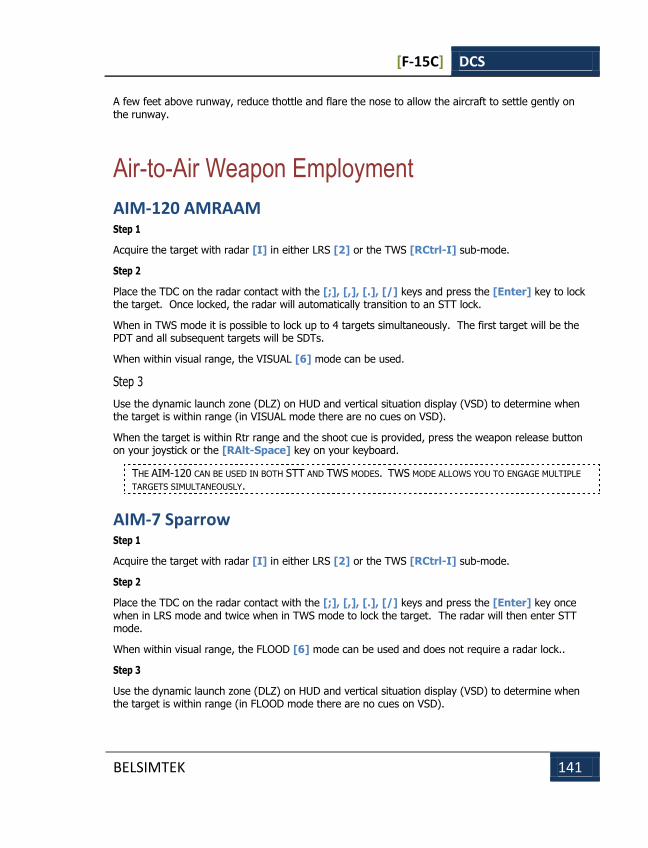
[F-15C] DCS
BELSIMTEK 141
A few feet above runway, reduce thottle and flare the nose to allow the aircraft to settle gently on the runway.
Air-to-Air Weapon Employment
AIM-120 AMRAAM Step 1
Acquire the target with radar [I] in either LRS [2] or the TWS [RCtrl-I] sub-mode.
Step 2
Place the TDC on the radar contact with the [;], [,], [.], [/] keys and press the [Enter] key to lock the target. Once locked, the radar will automatically transition to an STT lock.
When in TWS mode it is possible to lock up to 4 targets simultaneously. The first target will be the PDT and all subsequent targets will be SDTs.
When within visual range, the VISUAL [6] mode can be used.
Step 3
Use the dynamic launch zone (DLZ) on HUD and vertical situation display (VSD) to determine when the target is within range (in VISUAL mode there are no cues on VSD).
When the target is within Rtr range and the shoot cue is provided, press the weapon release button on your joystick or the [RAlt-Space] key on your keyboard.
THE AIM-120 CAN BE USED IN BOTH STT AND TWS MODES. TWS MODE ALLOWS YOU TO ENGAGE MULTIPLE
TARGETS SIMULTANEOUSLY.
AIM-7 Sparrow Step 1
Acquire the target with radar [I] in either LRS [2] or the TWS [RCtrl-I] sub-mode.
Step 2
Place the TDC on the radar contact with the [;], [,], [.], [/] keys and press the [Enter] key once when in LRS mode and twice when in TWS mode to lock the target. The radar will then enter STT mode.
When within visual range, the FLOOD [6] mode can be used and does not require a radar lock..
Step 3
Use the dynamic launch zone (DLZ) on HUD and vertical situation display (VSD) to determine when the target is within range (in FLOOD mode there are no cues on VSD).
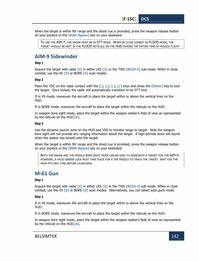
[F-15C] DCS
BELSIMTEK 142
When the target is within Rtr range and the shoot cue is provided, press the weapon release button on your joystick or the [RAlt-Space] key on your keyboard.
TO USE THE AIM-7, THE RADAR MUST BE IN STT MODE. WHEN IN CLOSE COMBAT IN FLOOD MODE, THE
TARGET SHOULD BE KEPT IN THE FLOOD RETICULE ON THE HUD DURING THE ENTIRE TIME OF MISSILE FLIGHT
AIM-9 Sidewinder Step 1
Acquire the target with radar [I] in either LRS [2] or the TWS [RCtrl-I] sub-mode. When in close combat, use the VS [3] or BORE [4] scan modes.
Step 2
Place the TDC on the radar contact with the [;], [,], [.], [/] keys and press the [Enter] key to lock the target. Once locked, the radar will automatically transition to an STT lock.
If in VS mode, maneuver the aircraft to place the target within or above the vertical lines on the HUD.
If in BORE mode, maneuver the aircraft to place the target within the reticule on the HUD.
In weapon bore sight mode, place the target within the weapon seeker’s field of view as represented by the reticule on the HUD.[6].
Step 3
Use the dynamic launch zone on the HUD and VSD to monitor range to target. Note the weapon bore sight will not provide any ranging information about the target. A high-pitched done will sound when the seeker has locked onto the target.
When the target is within Rtr range and the shoot cue is provided, press the weapon release button on your joystick or the [RAlt-Space] key on your keyboard.
BOTH THE RADAR AND THE MISSILE BORE SIGHT MODE CAN BE USED TO DESIGNATE A TARGET FOR THE AIM-9; HOWEVER, A VALID SEEKER LOCK MUST TAKE PLACE FOR A THE MISSILE TO TRACK THE TARGET. WAIT FOR THE
HIGH-PITCHED TONE BEFORE LAUNCHING.
M-61 Gun Step 1
Acquire the target with radar [I] in either LRS [2] or the TWS [RCtrl-I] sub-mode. When in close combat, use the VS [3] or BORE [4] scan modes. Alternatively, you can select auto guns mode.
Step 2
If in VS mode, maneuver the aircraft to place the target within or above the vertical lines on the HUD.
If in BORE mode, maneuver the aircraft to place the target within the reticule on the HUD.
In weapon bore sight mode, place the target within the weapon seeker’s field of view as represented by the reticule on the HUD.[6].

[F-15C] DCS
BELSIMTEK 143
In auto guns mode, place the static gun reticule over the target.
Step 3
If not already in auto guns mode, select the gun by pressing the [C] key; this will activate the GDS gun sight and place the radar in STT mode.
When the target is under the GDS pipper, fire by pressing the trigger on your joystick, or press the [Space] key on your keyboard.
The gun can be used without a radar lock but is much less accurate.

[F-15C] DCS
BELSIMTEK 144
SUPPLEMENTS SUPPLEMENTS
[F-15C] DCS
BELSIMTEK 145
SUPPLEMENTS
Acronym List AAA Anti-Aircraft Artillery
AC Alternating Current
ADF Automatic Direction Finder
ADI Attitude Direction Indicator
AF Airfield
AGL Above Ground Level
AH Attack Helicopter
ALT Altitude
AMMS Advanced Moving Map System
AOA Angle Of Attack
AP Autopilot
AP Armor Piercing
APU Auxiliary Power Unit
ASL Above Sea Level
ATC Air Traffic Control
ATGM Anti-Tank Guided Missile
BIT Built In Test
BP Battle Position
CAM Course Aerial
CAS Calibrated Air Speed
CDU Central Distribution Unit
CDM Course Doppler
CG Center of Gravity

[F-15C] DCS
BELSIMTEK 146
DC Direct Current
DCS Digital Combat Simulator
DH Desired Heading
DR Drift Angle
DST Distance
DT Desired Track
DTA Desired Track Angle
EDP Engine Dust Protectors
EEG Electronic Engine Governor
EGT Exhaust Gas Temperature
EO Electro Optical
ETA Estimated Time of Arrival
ETP Estimated Touchdown Point
FAC Forward Air Controller
FARP Forward Arming and Refueling Point
FEBA Forward Edge of Battle
FOV Field Of View
FPL Flight Plan
FSK Function Select Key
GG Gas Generator
GNSS Global Navigation Satellite System
GS Ground Speed
HDG Heading
HE High Explosive
HMS Helmet Mounted Sight
HSI Horizontal Situation Indicator

[F-15C] DCS
BELSIMTEK 147
HUD Head Up Display
IAF Initial Approach Fix
IAS Indicated Air Speed
IDM Inertial Doppler
IDS Information Display System
IFF Identify Friend or Foe
IFR Instrument Flight Rules
IFV Infantry Fighting Vehicle
INU Inertial Navigation Unit
IWP Initial Waypoint
LAT Latitude
LLT Linear Lead Turn
LONG Longitude
LWR Laser Warning Receiver
LWS Laser Warning System
MANPADS Man-Portable Air Defense System
ME Mission Editor
MILS Abbreviation for milliradian; Bomb/Gun sight settings were expressed in mils, an angular measurement; one degree was equal to 17.45 mils.
MRB Magnetic NDB Bearing
MWL Master Warning Light
NATO North Atlantic Treaty Organization
NDB Non Directional Beacon
NVG Night Vision Goggles
OEI One Engine Inoperative
[F-15C] DCS
BELSIMTEK 148
PT Free Turbine
PNK Russian "ПНК". Aircraft Flight and Navigation system
PrPNK Russian "ПрПНК". Aircraft Targeting, Flight and Navigation System
RAIM Receiver Autonomous Integrity Monitoring
RALT Radar Altitude
RB Radio Bearing
RMI Radio Magnetic Indicator
RPM Revolutions Per Minute
ROF Rate Of Fire
RTB Return To Base
SAI Stand-by Attitude Indicator
SAM Surface-to-Air Missile
STP Steerpoint
TAS True Air Speed
TCA True Track Angle
TH True Heading
TOW Takeoff Weight
TP Target Point
TV Television
TVM Television Monitor
UHF Ultra High Frequency
UTC Coordinated Universal Time
VHF Very High Frequency
VFR Visual Flight Rules
VMU Voice Message Unit
VNAV Vertical Navigation

[F-15C] DCS
BELSIMTEK 149
VOR VHF Omnidirectional Range
VVI Vertical Velocity Indicator
WCS Weapon Control System
WPT Waypoint
XTE Cross Track Error