david w. taylor naval ship research and development center · david w. taylor naval ship research...
TRANSCRIPT

DAVID W. TAYLOR NAVAL SHIP
RESEARCH AND DEVELOPMENT CENTERBethesda* Maryland 20084
AN INVESTIGATION OF APPENDAGE DRAG
SE
. AI P. LASKY•
L. r'2
Approved for Public Release: DISTRIBUTION UNLIUtTED
C A-0 SHIP PERFORMANCE DEPART1ENT
0 J
'-4
> issued October 1980 SPD-458-01(March 1972)
N. •-A
•~~1 01 286 -=• N

iI
DISCLAIMER NOTICE
THIS DOCUMENT IS BEST QUALITY
PRACTICABLE. THE COPY FURNISHEDTO DTIC CONTAINED A SIGNIFICANTNUMBER OF PAGES WHICH DO NOTREPRODUCE LEGIBLY.
t o

UNCLASSIFIEDSECU•tITY CLASSIFICATION OF THIS PAGE (When D.I. En.twed)
REPORT DOCUMENTATION PAGE READ INSTRUCTIONSREPORTDOCUMENTATIONPAGE _BEFORE COMPLETING FORM
* 1. REPORT NUMBER .VT ACCESSI' NO. 3. RECIPIENT'S CATALOG NUMBER
[. SPD-4 58-014 TITLE (and Subtitle) 5. TYPE OF REPORT & PERIOD COVERED
AN INVESTIGATION OF APPENDAGE DRAGA- SPD Report
6. PERFORMING ORG. REPORT NUMBER
7. AUTHOR(,s ". CONTRACT OR GRANT NUMBER(&)
Marc P./Lasky / i9. PERFORMING ORGANIZATION NAME AND ADDRESS 10. PROGRAM ELEMENT, PROJECT. TASK
David W. Taylor Naval Ship R&D Center AREA 6 WORK UNIT NUMBERS
Ship Performance Departmentv Code 1524Bethesda, MD 20084
II- CONTROLLING OFFICE NAME AND ADDRESS I.12. REPORT DATE
March 72 Reissued Oct 1980
13. NUMBER OF PAGES14. - - - 55 .
14. MONITORING AGENCY NAME A ADDRESSIl diffe.rnt trai Controllinj . fiieo ) 15. SECURITY CLASS. (of tll.roport)
Unclassified
1Sa,. DECL'ASSIFICATION/DOWNGR'ADINGSCHEDULE
Is. DISTRIBUTION STATEMENT (of this Report)
Approved for Public Re:.ease: DISTRIBUTION UNLIMTED
17. DISTRIBUTION STATEMENT (oft),& abstract entered in Block 20, It different train Report)
I8. SUPPLEMENTARY NOTES
Uk. KEY WORDS (Continue on reverie side li neceeoas ' and Identity by block number)
Appendage Drag; Resistance, Interaction and Scaling of Appendages; Reynoldsnumber
20. ,4STRtACT (Continue on rev.,,. side if necesgary and Identify by block numb*?)
The purpose of this report is to provide information about the resistance,interaction and scaling of appendages. A calculation procedure is developedthat can be used to compute the Reynolds number dependent components of
appendage drag. A correlation is made between the calculated values of drag
and data obtained from bare hull and appended ship-model resistance rests.This correlation indicates that t'he mathematical model is an effective means of
predicting the viscous drag of appendages and that the added drag due to pres-
.are as well as interaction between appendages and the hull form is of a smallFORM .DD ,•AN 7, 73 17 EDITION OF I NOV 6S IS OBSOLETE INtASSIFI•D - -,
!SN 0102-LF-014-6601
SECURITY CLASSIFICATION OF THIS PAGE (I&hIon Data Entered)
_ • ° o"

-. ?A&BLE OF CONTENTS(Page
AIDI..-STF7A-TtIE INFORŽ!TIO:N. .. * .... aaa *a*aa
I £NT?101.CT ION. & .aaa.2
VJiE!TcLEXPRESSIO'NS OF APEN.DAGE DRAG.. . .. . .. . .. *. . . . 4
M- APPDENDA,.GE MCO-PNENTS . . .a. .. . .. .. . . . . te .a 4
MIOCITY - AGNITUM XIDDIRECILtON. . .. ........ . ..*.*.* 4
I UDRSRTSADSAIIE FIN .o. . . . . . o .7
Reynolds Number Used to Obtaiu Cy. o . 0 . 0 . 0
flat Placre Friction R~esistance. ......... a..a*.8
S esl~stance. Due to Velocity Augmentation o . . 0 . . a a
1tess'jre or Separation Resistance .- . . . a * 0 * * . *
Add~d "Resistance fLue to Intersection with Hull or StrutB3arrel. . .. . . .. a*.aaa*.aa. **...-ts Drag Deo luntness of Trailing Edge .a*.***
GWLUP 1 -- Sa&--TiZG.. STIE!CTUBE BOSS INGS . AND. INTERMEDIATES7RUT. DARPRELS . . a . . . *.aa.a a a a 0 0 * a 0 a a a a .a
frIctic-a Resisraace and Reyrioles Number . . . . . . . . . 10
Pressure PFesistra-ce Corrected for Crossflo-w . . . . . . . .* 10(
Base Drag Due to Bluntness of 7airwater-Ending. .. aa*aa12
GMUP TV - BILGE KEELS AIM) SKEGS .a aaa apaa a13
~APP~D'A COfIMUVE-11 PROGRA,'t OF TH{E JNAThEF!ATtCAXL MlODEL .. a*aa. .14
CORPELAtION OF THE 11AT1lE-?*;7ICAL MODEL W1ITH !5.ODEL TESTS. .aaa aaa14
4 &3rJEF DESCRIPTION 0-7 THE SHlP-1.:ODELS &. & . .. a. 14
]?ALSENTATION OrFIPEL DATA ... * .aa.aa . *. ... ..
DISCUSSIONOF COME-SLATON. .o .a a .a.. .. .a .a .al
TErACTEON BEV.-EEN] APPENDAGES AID IHULLJ. aaaa aO ~
M~CLUS 'ZNS . . . a . .a .a .a a . . 20
. . a . . a 0 a . a a. 21
a2P~r;ED!X I -LISTING OF CO::PbTE-cR PUGýWtI . . . a . . . . . a a . . . . 27
"~PEN:DIX 11 - IN Fr OXM!T E0~CO.-PUTEP. Pr.OGI021 ,WPEN9l. . * 41 .A
APPEN:DIX:II - otrPr aW*00 90 0
R~EVERENCES . . . . . . . a . a a . . * aa*a*
C _ J
0 >"4.. -- 4 r
to Lk1w ~ ,.-4 ... mom"

"2 LIST OF FIGUpRS
Figure I - Graphical Representation of the Reynolds Number Page"Formula as a Function of Velocity. Length, andTemperature. . . . . , , . . . . a * . e . 0 . a * . 22
Figure 2 - Curves of Laminar, Transition and Turbulent FlatPlate Friction Coefficient as a Function of ReynoldsNumber * * * . e. . * . . . .. . v a 0 * a., •* * .23"Figure 3 - Comparison of Values of Appendage Drag Obtained fromthe Mathematical Model with those Deduced from CenterBare Hull and Appended Ship-Model Resistance Tests . . 24Figure 4 - Model Scale Differences Between Center Tests and the"1 athematical Model . .....
. 25Figure 4a - Comparison of Values of Appendage Drag-as a Percentageof Bare Hull Drag Deduced from Center Bare Hull and
Appended Ship-'!odel Resistance Tests . . . ...i
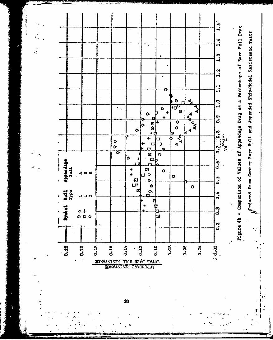
.. - . . . 26Figure 4b. - Com'qparison of Values of Appendage Drag as a Percentageo: of Bare -Hull Drag Deduced from Center Bare Hull andAppended Ship-Model Resistance Zests . o • , . • * * . . 27Figure 4c - Comparison of Values of Appendage Drag as a Percentage.of Bare Hull Drag Deduced from Center Bare Hull andAppended Ship-Model Resistance Tests 2 8 , . •.,.,2* .
LIS. OF TABLESTABLE I The Hull Forms . . . . .
16TABLE II -. The Appendage Suits.
" iii iI:

-
U'* .MDZNCLATI;RE
I*chord length
-S Coefficient of flat plate friction
Spressure drag Coe fficient
diameter
L 1en4th of a•pendase
base resistance due to bluntness of trailing edge"3. flatpltae frictonal resistance
"added resistance due to intersection
pressure or separition resistance%A Velocity augmented resistance
"planforn area of one side of appeadage
"projected area of base or trailin edge* thickness
* -, S thickness of base or trailing ecge (V valocity I
cross flow angle (angle between hull and appendage)S::neiatic viscosity
'C mass density
tI
•.5.
* - . . -i ii i
•

-, -
ABSTRACr
The purpose of this report io to provide information
about the resistance, interaction and scaling of appendages.
A calculation procedure is. developel that can be used to
compute the Reynolds number dependent components of appendage
drag. A correlation is made between the calculated values
of drag and data obtained ftom bare hull and & •ended
-ahip-model resistance tests. This correlation indicates
tbat the mathematical model is an effective means of
predicting the viscous drag of app ndages and that the added
'drag due to jressure as well as interaction between appendages
and the hull form is of a small order of magnitude.
AD.U41NISTRATIVE INFORflATION
This study was authorized under the Naval Ship Systems Co•and --
Exploratory Development Program in lHydrodynamdcst Budget Project 32, and
was funded under Subproject SF 35421, Task 1713.
Ai.
I -a - a

ýY,
I DRODUCTMO k
I
Ship appendages refer usually to element:- outside the main hull, such
as shafting, shaft supporting struts and bossings, power transmission pods
and struts, bilge keels and control surfaces. It has been common practice
to measure the drag of these a pendages as the difference In drag w -conducting resistance tests with a ship-model in the bare hull and the
appeuded cond•tlion. These measurements provide a gross assessment of the
total drag of appendages plus interaction effects for a particular design,.
but they do not give detailed drag data- for eachi appendage, nor inter-
t actions between hull and appendages.. The designer does not'have sufficient
Information to improve designs where the, combined drag is unduly high.
Furthermore the extrapolation, from model to Sull-scale,, of appendage drag
±s-questionable at best:.
"A procedure for designing appendages was presented in 1953 by Philip
-Handel * In his summary, Mandel states that scale effects of appendage--
=ea-ist•cnce ... are Lmportant not only in accounting for part of any discreq-
tanciez: between model power predictions and full-scale results but also ia
:establishiug the validity of comparative model testing conducted for the
purpose of evaluating competitive appendages-• Fundamental studies and tests
of individual appendages over a large range ofRey'nolds nuwbers are needed
for this purpose." In 1957, E. P. Clement conducted such'a study. using
-appendages from a planning boat Clement concluded that the resistarce
redictions based oa previous model. tests'were'.too high-by-about 2.9% when
they were compared with his tests. He-further- concluded that this error .Ya"
a scale effect due to the fact that below a Reynolds number of 106 the extrap-
olator used with the Schoenherr friction line was not steep enough. , In
.1.966, Hadler 3 developed mathematical ex.ressions for" predicting the drag of
planing boat appendage- and used Clement's work to determine the accuracy oE
his rmechod.
1 References are listed on page 55.
2
0 *i
0 The present task would appear to be to verify if the-works by Clement
and Hadler can be applied to displace'ment type surface-ships. The major
problem encountered in this area is in predicting the flow- In way of -the
appendages. l1hereas in a planing boat; it may be assumed-that the flow is
parallel to the bottom of the hull and has the some mag~aitude as the boat
speed, this is not necessarily the case for displacecneut ships.
This report.vwill. discuss -ways of eitimating the magnitude" and direction
of. the velocity in way of the appendages. Thenw amathematical model will
be developed for estimp-ing the.Reynolds number dependent drag of the
following.appendage components: *
-1. Rudders,
2. Shaft support struts,
3. Stabilizer fins,
-' 4. intermediate and main shafts,
5.. Sterntube bossings,
6.. Intermediate and main strut barrels,
7. Bilge Keels, and
8. Skegs.I
The results obtained from the mathematical modeL are then- correlated with
uodel.rest.data and there.is a.discussion.of the-induced'forces and the
interaction between the appendages and the'hull; --
-. S
.--
.I-
* It should be noted that although this report- does not., cover such appendagesas power transmission pods or right angle dr.;ve.units, information regaidingthese appendages may be found in References'4"and-5;*It*is hoped, that at alater date expressions will be developed for these appendages-as there would
appear to be quite a demand for this information- in the future.
3
* S *A
" .... ".MATHEMATICAL EXPRISSIO,•'S OF. APPENDAGE DAG
.In.the development.of mathematical expiessions-that cea predict the, drag
of the aforementioned appendages.it was necessary- to*rmake-assuxnptions so
that the calculations. could be made'.with :relative .ease and still, be
applicable.,..The first .major.assumptio-.is-.that- the-appendages can be
divided into their, component .parts,' the drag-of-each" component being
calculated separately and .therefore. the:total-appendage-drag is equal to'
the sum of the drag.of each appendage; -The'second-majora-ssumption is
that the drag.of.the znpendages is considered-:to-be-viscou: in nature.,
(These assumptions AlI be discussed:In- further- detail'later, in the tex't.).
Other assumptions will be discussed:for-each- case and-specific references
are-noted next to.each expression. '
THE APPEIDAGE COMOPONENTS -. -.
The appendages. considered. herein are brqken- down into the followLig
.groiups: - - ("Group I Rudders, struts, and stabilizer fins;
Group II Steratube bossings, intermediate shafts, main shbf:s,.tand intermediate strut barrels;.
Group III Main strut barrels;
Group- IV - Bilge keels and skegs.
-Groups I and II are treated as tw-io-dimensiornal'sufaces'C-roup•lII jis treated
like a body of revolution and Group IV is treated similar to a flat plate
friction plane..
VELOCITY - MAGNITUDE A;ND DIPECTION
In the preliminary design stage, more often- than-not;" the designer can
only apyroximate the velocity at the'stern. -At-presentthere-are no simple -
4
* . - I -" - -"" -'' o
:. -.., . , .-. - • • . :
.- -. . - -. - - -

methods for predicting the flow in way of'a ship's appendages. The Douglass
S•Aircraft Company, Inc. has developed* a* computer'programufor calculating
potential flow about arbitrary three-dimensional-bodies* (Reference 6).
" •The Douglass program has been used successfully- in several'cases to predict
the flow about ship hulls. There has'been, some-success-in-predicting the
pressure distributionover a bow-mountedHsonarwome. "owever. in the
early"stages'of this project, an attempt-was'made-to-predict the flow at
the stern of a ship, a-id it,.was concluce" - that- this-method-was too expensive,
time consuming, and necessitated- information- which- might- not necessarily.
be available to-tbe"user during, the* prellmln7r" design- stage of the hull.
For simplicity, if we restrict'this'investigdtion-to ships with
multiscrew" propulsion systems that have some-type-of transom, stern with a
relatively flat bottom, we may thenassume- that-the-wake-fraction, for this
type of ship; will normally range from-zero-to-eight-percent. Therefore.
we may use as the loc~l velocity in way'of-the appendage) the freestrean
velocity or modify it bya wake fraction" (based' on data for- a similar ship
which has-previously been tested); *It is felt-thatiin'terms-of percentages.
the error due to'this assumptionwouldbe-approximately'O'to 8 percent
(at most) of the velocity as measured from-a'wake survey.
As for the direction of the local velocity; it -is assumed that the struts,
skegs, bilge keels, stabilizer-fins and- rudders- align-with the flow. Further.
the direction of flow past cylindrical bodies-such'as-shafts, sterntube
bossings, strut barrels, and fairwaters is assumed- to -be parallel to the
hull and thet there is no transverse crossflow;" Therefcres the dirertion
of the flow over these appendages can be estimated-to'be the angle they
make (locally) with the hull.
- This assumes that the velocity error will bero greater than the wakefraction for the hull form.
-ii 5,
i~ii " :e
I-
THE FRICTION F%ýAULATION
The Schoenherr friction line, (Reference 8), has been used for all
friction calculations on the appendages. The numerical valuts of
derived from the Schoenherr formula apply to the viscous component cf
flat surfaces whereas other friction lines commonly used by naval
architects in determiuing the frictional resistance of ships might
Incorporate various degrees of a form factor.
Therefore, since the Schoenherr formulation is considered to be a
baseline, the expressions used to calculate appendage drag will relate the
geometric parameters of the appendage to the corresponding flat plate
friction coefficient.
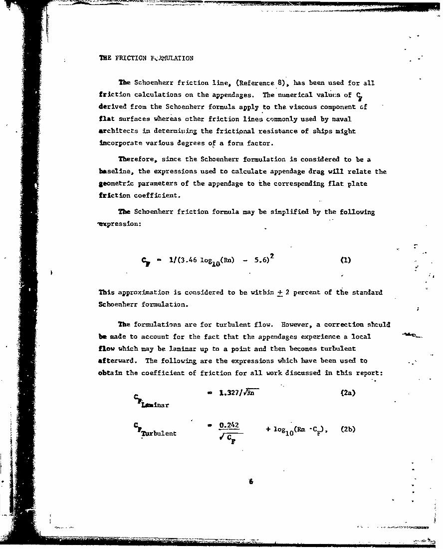
The Schoenherr friction formula may be simplified by the following
vxpression:
Cp - 1/(3.46 log1 o(Rn) - 2 (1)
.- ,;a
This approximation is considered to be within + 2 percent of the standard
Schoenherr formulation.
The formulations are for turbulent flow. However, a correction shculd
be made to account for the fact that the appendages experience a local
flow which may be laminar up to a point and then becomes turbulent
afterward. The following are the expressions which have been used to
obtain the coefficient of friction for all work discussed in this report:
1.327/'-- (2a)
Laminar
CPubulent 0.242 + loglo(Rn CF), (2b)
F
n 10T| O
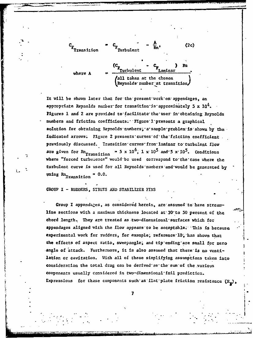
C A (cT':ransition " CF - 'ule " (2c)F .snTurbulent an a
where A ( Turbulent CVLaminar)f
(eall taken at the chosenReynolds" numberrat transition)
It will be shown later that forthe'present'work-on- appendages, an
appropriate Reynolds number'for transition- s' approximately 5 x 10⁴.
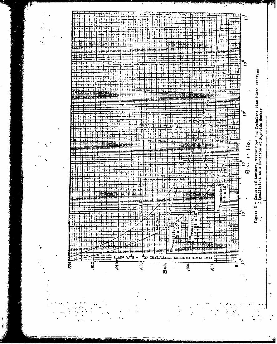
Figures 1 and 2 are provided to facilitate, the- user in- obtaining Reynolds
numbers and friction coefficients;''Figure'1"presents a graphical
solution for obtaining Reynolds 'numbers;- a* sample- problem- is* shown by the
indicated arrows; Figure 2 presents'curves'of"the'friction coefficient
previously discussed. Transition-curves- from-laminar to'turbulent flow
are given for RnTransition = 5 x 10⁴; 1 x 10⁵. and5 x"10 5 . Conditions
where "forced turbuience" would-be used correspond to-the'case where the
turbulent curve is used for all Reynolds-numbers'and-would be generated by
using Rniransition 0.0.
GROUP I - RUDDEPS, STRUTS AND STABILIZER FINS
Group I appenda-es, as considered herein, are'assumed-to have stream-
line sections with a maximum thickness located at' 30-to 50 percent of the
chord length.. They are treated as two-dimensional'surfaces which forappendages aligned with the flow appears'to be acceptable; '"his is becauseexperimental work for rudders, for example; reference-lO,'has shown that
the effects of aspect ratio, sweepangle; and tip'ending'are small for zero
-angle of attack. Furthermore, it is also assumed that there' is no venti-r!
lation or cavitation. With all of these simplifying assumptions taken into
consideration the total drag can be derived'as'the'sum'of the .various
components usually considered in two-dimensional-foil prediction.
Expressions for these components such'as flat'plate friction resistance -(RP&
7
• o -
• - - ,--'.•-- ,~ - , ~
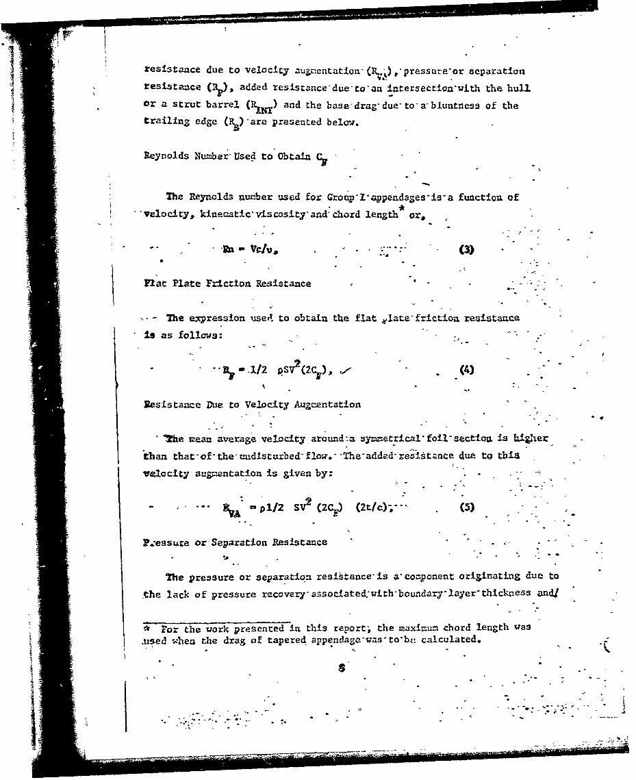
resistance due to velocicy augnentatIonr (R..d),'pressare-or separation
resistance added resistance due- to an Intersection-with the hull
or a strut barrel (R.) and the base drag, due- to- a, bluntness of the
trailing edge ( -)are presented below.
Reynolds Number" Used to Obt aia Cy
The Reynolds nunber used for Group-Iappendages-is-a function of
-'velocity, kinematic, viscosit" and* chord length or,
-,4
71st Plate Friction Resistance ' -
"- -he expression useA to obtain the flat elate friction resistaace
U as follows:,
l 1./3,.2 •SV2 (2C.)
Resistance Due to Velocity Augtzentation
* 2he mean average velocity around-a syzmetrical" foil- sectioa Is hig/her
"than that- of- the- audisturbed" flow.- The'added- resistance due to this
va.locity augrentation is given by: .....
eA pl/2 SV2 (2Cy) (2t/c);": (5)
F cessure or Separation Resistance - ""
The pressure or separation resistance'is s'component originating due to
Ohe lack of pressure recovery* associated.,withboundary-layer- thickness andj
F -or the work presented in this report; the maximum chord length was
.used -AAea the drag of tapered appendaga'was to'bk; calculated.
." - • Roo

k-I
-, or separation along the afterbody of"foil'and'strut'sections. The
expression for approximating the pressure- drag'is-given as follows:
R 1/2 pSV2 (2C,) 60 (t/c)4 - (6)IipAdded Resistance Due to Intersection with'iull-or'Strut Barrel
The added resistance due to-an intersection-of any-of- these appendagesJ with another surface will be'treated as'Ifit-were-an intersection with
"a flat wall. It is speculated that, "when a*wing or*strut- adjoins a wall
(or an end plate), the boundary layers of-both; the wind-and the wall,
Join each other. Subjected to the pressure- gradient* along the rear of
the foil, section* the -boundary -layer is- further retarded;- and additional
pressure drag (i.e., interference drag) arises."1 1 It-should be noted
that for very thin sections (t/c <.081 this interference* drag might become
- -,negative. The expression for estimating-this-drag' component is given
below:
R= 1/2 pV2t2 .75(tic)'- 0.0003/(t/c (7)RLO L
Base Drag Due to Bluntness of Trailing EdgeI r-
The base drag of foil section with blunt trailing'edges may be
approximated with- the following expression.
Ra 1/2p 1J 0.13513 c Ad c(8)
GROUP II - SHAFTING, STEWITUBE BOSSINGS AND INTE1-1EDIATE STMUT BARRELS
In Order to estimate the drag of the shafting, it-was necessary to
divide this appendage into the following sections:" (I)" Intermediate
shaft (between the sterntube bossing and the intermediate strut barrel),
and (2) main shaft (between the intermediate strut barrel and the main
9
4: ". .. - --
- - --.---.--- "-- -.. " "

Strut barrel). The resistance components of Croup- 11" appendages are thefricticn?• resistance (R. and the pressure resistance corrected for
Crosstow (1y).
fricticn Resistance and Reynolds Number
The Reynolds number. used .in estitading the frictional dra3 is basedon th.e a2pendage length along the 1ongitudinal-axfs; Therefore.,
(9 .
where -"
Z le.ength of appendaga along the longitudiual:axis-(for ster9tubebossings, the length is taken'to'the'intersection-with the hullalong -he" shaft ceaterline),
The fricti6n resistance =aW be determined-byt the-follow-n& e-xpression.
o 3js/ pLDV'wS
* (10) (
!Pressure Resistance Corrected for Crossflow
The expresslon used to estimate the pressure"drag has been taken froma derivation proposed by Roarner (reference 11), The*general form of theequation is:
23Y. 1/2 pLDV C Sin a'.)
The pressure drag coefficient CC.) may be further defined for non-cavdtating-d ca'rI-tating flows. The proposed definition of C follows fron work
presented In reference 1l. page 10-8, Figure 15a; This figure presentsdrag coefficients as a function of cavitationnumber- for flows that are
10
-.....

"above and below the critical Reynolds number for separation. The
parameters used to describe the flow are Reynolds number (Rn) and
cavitation number (a).
Rn - D (12)V
S- 2D.(13)
S(P ambi - P ap)/(1/2 p V2) (13)
where
Pa--i. - ambient pressure acting at the centroid of theappendage,
- vapor pressure of the surrounding fluid.yap
The expressions for the pressure drag coefficient represent the afore-
mentioned curves in reference 1i in polynomial form and are given below
for various flow conditions.
kn < 5 X 10 anr1 u>2.5,C1 - 1. 17Rn > 5 x 10⁵ and 0>2.5, Non-Cavitating Flows
S- 0.50
RM <5 x 10⁵ and cr <2.5,
C" -. 5 + .5a - .052 a2 + .046 C -3.061 a4 + .014 C 5 ,
ft >5 x 10 and 2.1<0 < 2.5,
S-6.125 - 2.25 a, Cavitatiing Flows5
Rn >5 x 10 and < 2.1,
C" -. 5 + .5a- .039 a2 + .006 .
11

CGROUP 1IlT -AIN STRL-C BARRLS (
The co!ponents of a main strut barrel are:
(a) strut barrel,
(b) propeller hub,
W(c) fairwater.
These ce-poaants together are considered one unit.
The components of re-A-stance for these appendiges are friction
resistance (.±, pressure resistance. corrected for crossflow and tihe
base drag due to the bluntness of the* fairwater trailing tip.- (R&). Theapresslons used to estImate the resistance-due. to friction and pressure
are the same as the one-; for Group II appendages-Ecquations (9) through.
(13)).
Base Drag Wue to Bluntness of Fairwater-Ending
Accordlng to Roerner, the base drag of three- dimensional bodies very,similar to the fairwater (projectiles- fuselages-and.. elipsoids- for example)
S' found to depend largely on the- length- of- the- forebody, its surface
*6ndtions., and the ratio of ba3e to body diameter; -The expression used
Mo..estluate the resistance due to the bluntness- of, the- fairwater-endiu. Is:
RI _V2 12 3 ___S 4" [V.029. (/B/D) /(2ACE(L/D)) 1 (14) "
4 I'.-.tere
D - caxim-um diameter of appendage,
D - diameter of base (gee above),
L = Jlength of appendage along the longitudinal axis if blunt orroun.ded trailing end, use the- extended- length- i;e. * the length
the appendage would be If it were not blunt.
12 -(
.--- -

I - in
"- C@ROUP IV - BILGE KEELS AXID SKEGS
The resistance of bilge keels and skegs is" treated"similar to theI
drag of a flat plate. This assumes that these appendages are alignied
with the flow.'- It should be noted that, generally" skegs are considered
as an Integral part of the bare hull form and not'as a separate appendage.
The e~xression for estimating the resistance'of'this group-of appendages
S 2/2 SV2 C(15)
where
S wetted surface area of the appendageminus'the'wetted surfacearea of that part of the hull that has been" covered up by theappendage. By tak•-ng the wetted-surface-in this manner, theloss of bare hull friction drag due- to a net- loss of wetted""siurface on the bare hull can be compensated for.
I
*he Reynolds ntmber to be used to obtain the-flat plate friction
• coefficient is a function of the velocity,'length-of appendage, and kine-
Smatic viscosity, as follows: "
VL. - (16) -
'1p

!I
"APPENDU A CONfPUTER PROGIRA1• OF THE N-ITiEU!TICAL M4ODEL
The expressions derived in the previous' section" for calculating the
drag of various appendages have been used as: the'basis for a computer
routine named APPEND. Details of the computer program are presented iii
Appendices I through III wit.h the routine/algorithm" ±_Fortraýn presented
In Appendix i; input format andoutput-format' inAppendices XI.and III
respectively.
"CORRELA&TION OF THz MLAIHEŽ!ATICAL WDEL"WITH MODEL TESTS
In the presentation of any calculation method, itfwould be'most
-desirable if the expressions could be--prove." out'by- experimental data.
F oar the case of appendages•, this would- involve the- testing of various
"--sizes- (scale- effect)-" shapes, and comblnations-with one another (inter-
i ctIcns). "" However," it was not possIble to conduct* such- aa• experimat•-al
Vrcgrxa= for this study. It was necessary; therefore; to'simulate a data
"-"base which could substitute for the test program.
The decision was made to make use of-the results of'previous model
tests conducted by the :'aval Ship Research' and Development" Center. This
-methud" involved the- selection of, fourteen shipý-models- that'had been tasted
In the bare hull and appended modes'for resistance; The drag of the
ppendeaes'as a group was then obtained from the difference in resitantce
"of the two modes and compared to the'results obtained by'using' the eynress-
tons presented herein.- A f airing of'the" data-has been made in order to
facilitate'general comparisons.
P. BRIEF DESCRIPTION'OF TiE SUIP-MODELS
In general, the fourteen ship-models chosen for-ths sttdy were of the
twin screw prop Uslion'type and represent'three'basic-bhall forms wih
1IV
transom type sterns. Tables I and II present, a-more-detailed description" of the hull forms and their appendages.
PRESENTATION OF MODEL DATA
"As stated previously, it Is-most desirable'to'present-some experi-mental data In'order-to verify-a mathematical'model;-'Keeping in mind
"* *"that the mathematicalrmodel presented-herc.in- is supposed- to"represent the" - ~- Reynolds number- dependent components-of"the"appendage-drag, then the
data should be presented in such a'manner-soas to"describe'visually tht- 'answers to-the"following questions. "First-s"and'most"important, are the
expressions able-to predict within a"reasonable-tolerance the Reynoldsnumber dependent drag-of the various appendages- and second, what arethe pcssible sources of error inherent-to-thprmathematical-model and howcan they be compensated for? The data-are-presented,-therefore, in twoways in order to determine if the-answers to'the-above-questions are just"a function of'the-individual appendage suit in question-or if there are
t general trends which- can be- applied to-any- appendage suit.
-....... .. Figure 3 presents the values of'appendage-drag-(injcoefficient form)as calculated-from the mathematical model using'both"arfriction linebased on forced-turbulence at tl-e lower-Reynolds numbers and on a"transition-Reynolds nu..ber equal to5 xu10 .(these-friction-lines may be --
"-• - seen in Figure 2)., Also presented-in*Figure 3"are-the-appendage drag data-... .. obtained from model tests as previously described;---The differences in
model appendage-drag coefficient for various-hull'forms of the samedesignation, e.g. three 3-D forms,-are-due-to differences in the models -not readily apparent- from the descriptive-parameters-listed in Tables Iaad 11. The predicted values of Reynolds number-dependent appendageresistance appear to be in close-agreement with'the'model data exceptwhere "humps" appear. To further investigate- this-phenomena, Figure 4 hasbeen prepared. It presents the difference between the-calculated values
15
A .. ".1ti lII,
I:l il "
S..
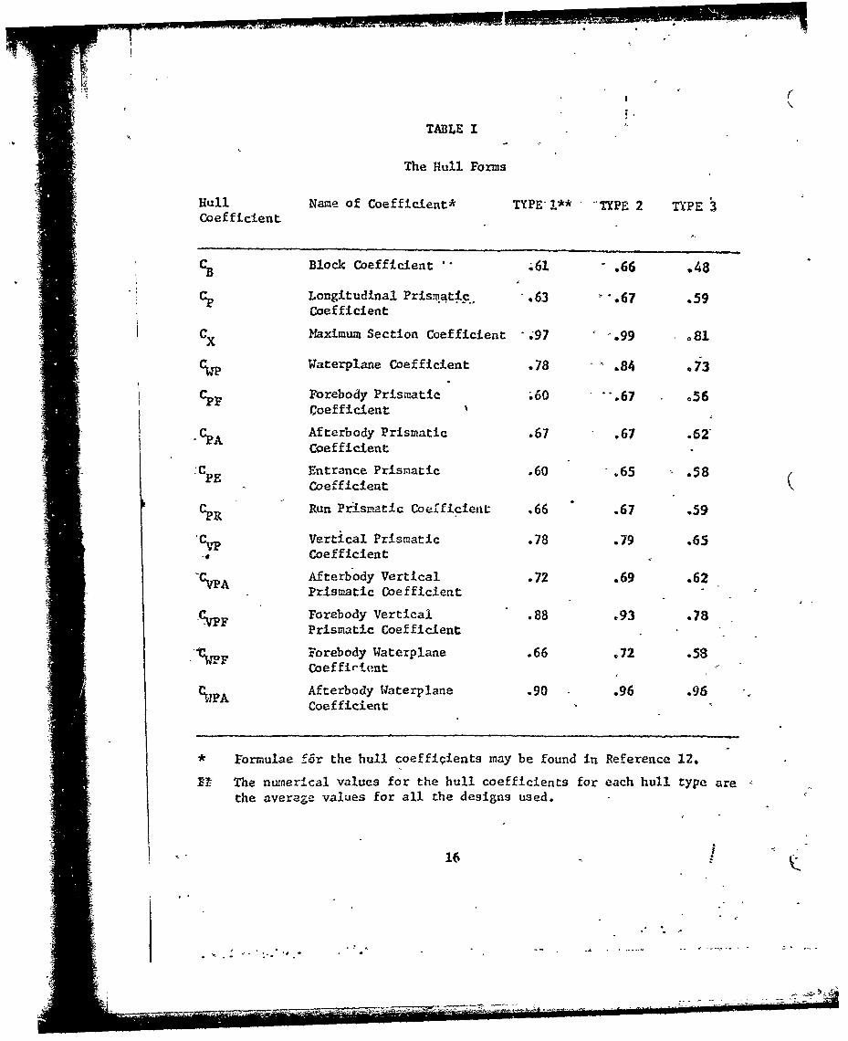
TABLE I
The Hull Forms
Hull Name of Coefficient* TYPE !** -TYPE 2 TYPECoefficient
CB Block Coefficient A6 - .66 .48
Longitudinal PrismatI•c. .63 -. 67 .59Coefficient
CX Maximum Section Coefficient 0.97 '.99 o81
CT Waterplane Coefficient .78 -" .84 073
Forebody Prismatic .60 -. 67 .56Coefficient
""A Afterbody Prismatic .67 .67 .62'Coefficient
:CPE Entrance Prismatic .60 .65 .58Coefficient
CPR Run Pr'ismatic Coefficient .66 .67 .59
CvT Vertical Prismatic .78 .79 .65Coefficient
"CvpA Afterbody Vertical .72 .69 .62Prismatic Coefficient
-C Forebody Vertical .88 .93 .78Prismatic Coefficient
Forebody Waterplane .66 .72 .58Coeffirtent
%PA Afterbody Waterplane .90 .96 .96Coefficient
• Formulae f~r the hull coeffIcients may be found in Reference 12.
I- The numerIcal values for the hull coefficients for each hull type arethe average values for all the designs used.
16-
.i ... .:. .
__ _ _ -

C-,C-)4 4 C C-j
1- , q C4 ra C4 C3 C4 Ctii z j i
* .H
.4W SlA g C- Cq C- 4 C4C4CAC - i e
8-t4
NN N 4N C 4N a N4C*4 4 C-4 4 4 C4 C- 4P
1400
to 0
V) V. NN ~JrC4.g.4 044~
9-'a.
P4 P4q-
0. to
H r4 V4- q 4C q- nm m o -
174
Joe J

(using the transition Reynolds number 5 x 10⁴) and the model data in the
form of percent dlfjerence and the actual magnitude in pounds. These
absolute and relative differences are presented as a function of the model
speed non-dimensionalized by the design speed value-"
Values of appendage resistance as a percentage of bare hull resistance
for the fourteen selected models are presented versus speed-length ratio
in Figures 4a, 4b, and 4c.
DISCUSSION OF CORRELATION
In order tJ discuss the correlation of the results obtained from the
mathematical mi-del to the model data, the speed. range will be broken down
into two components. The first speed-range will be defined to be below
design speed and the second will be above design" speed. ,The design speed
forr hull forms 1 and 2 is approximately equal to a speed-length ratio of
J8 and for hull form 3 the design speed-length-ratio-is about 1.2. It Is
.assuzed that the aipendage drag below design speed is for the most part:
dependent-on Reynolds nautber and that the- coatribution of the Fr..'de depend-
ent resistance becomes'a factor slightly-below and about- design speed.
Pigure 4 indicates that the agreement between the mathematical model
-and the model data below design speed is very good. For example, the
-.average magnitude of this difference at 80 percent design speed is less than
0.2 pomuds. Vle may, therefore, deduce that the mathematical model.is valid
In-this speed range. The deviation from the mean maybe caused by..a
misalignment of such appendages as struts, stabilizer fins, bilge keels,
etc., to the flow and will be discussed later in the'text. For now, it will
be called an induced drag (PR) that is, in nature, independent of Reynolds
number. - ,
The case for the differences between the results from the mathematical
rmodel and the model data is similar for the higher speed range. However,
.. "8•- . .8
4- . - ..-
- '• " -" .' "' " .-.' :-.. . ... " -.. . "

the magni.tude is larger, which would tend to confirm the second part of our
assumption, I.e., that the Froude number dependent resistance-has an effect
at the higher speed-values. The shape of the curve through the data is still
more evidence indicating the Froude nuTber dependence of this component of
the appendage drag.
INTERACTION BETWEEN APPENDAGES AND HULL
If it is assu.med that part of the difference between the calculated
values and those data deduced from the model resistance tests is due to
the previously mentioned induced resistance caused by misalignment to the
flow, then the question arises as to what causes the -est of the difference?
This may be answered by using some deductive reasoning.
It is a well known phenomenon that an appended model will not necessar-
ily have the same trim clharacteristics as a bare hull model. It is also
known that the tr.-'= of a model has an effect on its wave making resistance.
Now, it will be recalled that the model data used for the verification of
"the mathematical madel were obtained by subtracting- the bare hull model
resistance from the appended hull model resistance. Furthermcre, since
we were able to predict all but 0.2 pounds of the appendage drag up to 80
percent of design speed (this being almost ttally dependent on Reynolds
number) there is no reason to believe that we do not have the same relative
accuracy for predicting Reynolds number dependent drag above the design
speed. It appears to be reasonable, therefore,'to deduce that the remainde'--of the difference between the values obtained from the calculation procedure
and the model data is caused by the interaction-of the-appendages On the hull
form and that this interaction is a resistance- that is'Froude number
dependent and wave making In nature.
19
U r

CONCLUSIONS
Sulmariz±ng what has been accomplished in* thepreceding chapterss the
follo•ing conclusions nay be drawn.
1. A mathemnatical model has been developed for the predictioa
of the viscous components for appendage drag.
2. The predictions obtained from .the mathematical model have
been correlated with nodel appendage 'reslstance'dataobtained from the
results of fourteen ship-nodel resistaace tests'and'the mathematical model
was found to be an effective means of predicting- appendge drag.
The differences bet-4een the results from the mathematical model and
the model data appear to be due to two basik resistance components. i.e.,
Induced drag due to misalignZent of an appendage to the flow and a Froude
S humber dependent drag due to the interaction-between theappendagr.c and
-the hull form. These effects will be considered at greater length as""
'bis, study progresses. ".
3,. A Fortran IV comipter program, refer to Appendix I1 to be
used on the Center's CDC 6700 .comquter has-been* developed using the
Ssathenatical expressions presý-nted herein. The computer program as presented
herein utilizes excessive core space and is presently-being modified. The
modified version will be available by 1 karchl1972; The program also contains
en error ln the base drag formulation;-howevert this'error is being corrected
In the modified version. The present form will provide correct drag values
&s long as base drag terns are not needed.
-WO-
I . . "
_. -......-..-. " . ,;,, --

RECOMENDATIONS
A procedure for calculating the vector lift and-drag- components of the
"appendages could be developed, 'and their- effect -on- the- change- in trim angle
correlated to the added appendage drag'due to-change-in-underway trim.
This could be done by assurning that the forces-acting-on-the appendages
are located at the centroid of the appendages;*then-by taking the sum of
the moments about the center of flotation-,the'chanie-in-trim due to the
addition of appendages could be calculated;,-These- developments would be
very helpful to the designer.
Art experimental study should be conducted"on-a-set'of carefully
selected geosims to verify the scaling'techntque;.--This- study should also
Indicate if a correlation allowance for appendages-Is necessary. Since ft
may be difficult to conduct some phases'of such-an-experimental program Ir
a towing tank due to the size of some of-the-larger-geoslm" appendages, the
use of a subsonic wind tunnel may be cons dered'as-complcmenting the work
done In a towing tank.
21
* t
a....
,- *--
S--

*i IT
.. -V
lowa
ca
.4.4
L.l.........................
as:1. -
ta
c I
22 r
:0 _4 1: .-
-*
S-~--- - - - - - -o
* r TIE~ : .: F4 1 it --. ).4.4
-Z-
-1-I
C4
Tf- N
Laa
;r4,
- -'
C3 *2+.

0 EAA IkDUCED FROM EL RES•ISTAXCS TESTS
. ANALYIICAL PiRDIZCTOz1 USING; FORCFD jtUpuZ6-;CE
J- ZALY1ICAL PR-DICTIOC USING R OF 5 X 10⁴,__ ._____ __ '-Tr'_._',!. _L L_ _LoL
i T _
I _ L__ " ,L.._L rFl --t -F
IT E[ !, -t I | -6 .7 8 .9 1 to i2 6 tAS 15 .6 ,S .6 7 .8 .96 i •) 1 ....3
ý7 . 9 i-O r -i :2$?-6i4 i:5 IA 1' .5--18 ' . .1 f- 5~ 1 -T6
_ .I , .j t _ I '1 I J -_ I L •! . 1 . 1 t
14i
:L _ _ _• _ I !"I; tt IjI~! .lc! -f ~ ~ l
&" j.I 1 !I rl .I.w I~JI-_L -.L
3 ,L
- ,_ _ I . d -- . - w l... ."' -s' L. . .. -
'-~-- " .:o.-L -,,, ..-. ;' i t 2 i i i , I II i fj !
o •, . •- -• ) i . t i ll-4 - ... .. - _ _ • _ ' , .,I _Jo !._ U __.. .. 1 1 1 t l~
;_L_ ), t!.ui I to_ !. 12•! ! ! .*... I '.a .
2J...,....lfC. I....L. -5:.
Z 12
0• .4..5 .6 7A - 9 W t.4 3 .6 7 .8 .9 1 01.1 .3 A .5 .6 .Y .8 .9.] .8 .9 tO !.1 2 '/34
.... ...... L
. .. . ..-r*I _ - i I I 1 6!
--- ' "I-L L .
-.8 .9 to . .3 - -.7_-.a 79 -j .2 23 .4 .5 .6 7 .8 .91 to 1 .3 1A .-. .8 . t.,:
- Sf-F1ED - LENGT 111 RTIO (/lFPiure 3 - Comparison of Values of Appendage Drag Obtailned from
.the Mathematical MIodel with those Deduced from,Cent.er Bare 1•ulL and App.-n'ed Ship-&-odel
Resistance Tests 24

4:4
.~ t.1
*~ & 1
1*'( .cu il
c* ILo 0a ao~0
-'a -
*9 V
~'4)'
414
C40 41.4
52

-V -3
V4£
0.
SattnJ
* 0 co
v4a C:
4T -: u-I' ~t__ .4 I
1 1_ _4 u_0
C! * u I C! cj Id
23ISIY TMHJ aa~ 7IJ
AI ci--
:4
00
00
ogo
- -o 0
W4, C6V-4: 0- 1
000
Q '-4 0, 401.-4 r.4 p.C) ) C
Z)N-VISISUU~ TM Hif-I;Gaa~v~sipa aama
- - - - - - -- - - - - - - - - - - --2-41

0 000
%a4 o14 a
q~' 0 2
-g -, = ,
14 a0 +
ton
* 0 4 1 o w+ U:-ý
.4 0
1+ 0
cec
0M aua V33NIVISIl~a 3OW.
0 ..28
+ '.%

is
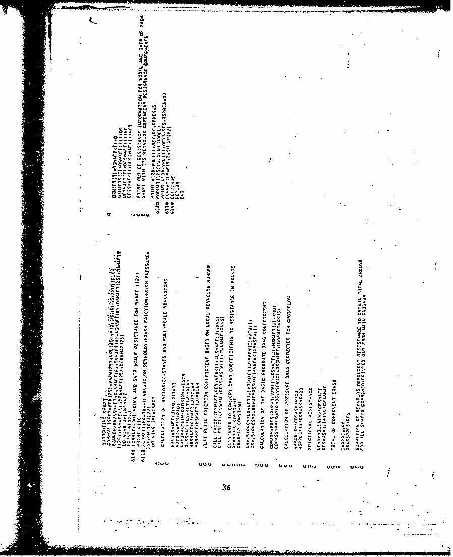
APPENDIX I -LISTING OF~ COMPUTER PROGRM1
APPEND is a Fortran computer prograin which may'be used to calculate
the Reynolds nuo.ber dependent resistance of the-appendages previously
mentioned in this text. The program, which-hasbeen-writtea for- the center's
CDC 6700 computer, will calculate appendage- drag- for any'size appendage,
I.e., model-scale or full-scale. APPEND consists of" the following sub-
routines: RUDDER, STRUT, FIN, SHAFT, BOSS, MAIN, BILGE, SKEG, and FRICE6
and the function PRESUR. In general, .the first eight subroutines are used
to calculate the various viscous drag components-of the appendage indicated
by the title. Subroutines FRICT is used"to" calculate the frictioa coefficient4
(CF), based on a Reynilds. number of transition of 5 x 10 Function
PRESUR is used to calculate the basic pressure coefficient described in
equation (11).
2
"______I
____

t~0- 1- CL..
**R 004 c x
-a- -1~ -j .-m .z Li t, 0-e.C16 0. ,." 00 :L!z % 00
727, ex.0 .C?.M0 :1 n.. CL0 c0 -. -. -.Q a- -- O " " O n
- t.- J.I.j abj.. 'C0. SAC. Gm- w 4M Vt. U, * 0.%
VI~ 0.0 44C CO. .- - 1 oaa..- ou ... o w-o m .....wCL *n Z 4xn wvv a >~ I-~ > .3->on=noa0C
00 .r~. .m 4 p-UIU4 m .J~- ~ - -.- ia-----------
2 ayccIn9
IQ .JU.
U. a 0 - 0- 0 t- w! 6- U, ub c bw 0. . -4 C - 0 a r, ou
-~~~U t.. a W4- I. .5 4.4
W* :I -j "3 WW
14... ka 0. ga U 4 - 0 5.l,%Aa- C . 4s0 W x o;: D -l.0 ?-
- .: .-n1- Ati Ga X 90 0 Ue .-UIt a--" . - X C I -a.a~Cna k.
-- L o.n.vor I
1 4-A w ccCA aa 0 ~ l- A A. - a. - -
o n/ 14.. 0 61 n.' %Au. -J4.3~ X-. CL .4. U) w n .. 4 a b-pA':-.4 w -.a r. P¶4 4- 514 PC j Vt .1
IC LaQ an~- nIc 4.C '3 1145 -4 - 8I.va I. nW4 4,t b-it ;.! -- X X .f,4a
.0 ;1- -0 usi x X.0 '4 a. W I
T- a.454 .17 x 5 4 Va XX A -. 4 0
V7W XO Mnn &a w nnaZX-9 IDt uZ 430 xn. a. 1-9- cc
Mua X al-L W; 7 n 4 J'4 X WIO a 5-
aA x .. ~ l x. W 14 40P WTa- 0 5 4 11 n o
- -> ZZ al ua a.n a~z. Xoz -. 4 --. Ml. V, -V40 9 -j :n l<. a 5aw-x
0~ V14. 90 7.J = 3 a- " -,? W) Ca. cc .j-4a-Q.,40-t.. X b-..7 CLm 00 U.j j 4a-.4 a
or ~ -n ~ t1 . -10 4I.t' .7* a-1 0ý I ý; It.- l n-- .. i a. C5 : -a " ,
7Uj.4 ~ 4 L- n 05 - ..- 9(/1 CC4W O v 0-j -1 0 ~ .X X-Qm umý a9.a-O' 06j~ x ~ f O Onj i ~u~4 7
-a a~. .r.z. a-4 0./0~.., 1 - .-- - a3ai

OR
a- 3 2ofW . I.. W ; hi 94
4-A 000 2hh
1, 0 - 4 4 w hfi
Z0% I- Wk 6- f
hij V V2i-W M. _
C51 10 ~ A. it 0ii 9. s- C3wl 0 44 :; 44 &9 #0 W54 V ~
00 1 3 5: 6) M I. & a r'0 99 hii go I-A Do L"b U, I-d =
U, is. 0 0 WiW 3D 0lid bWW "N i 0 ~ V WO
00~Z Mom 0 Z. I -521K @ -B rC~~~~~~~ i.5 hi30 hiiSL 0 W aBtJ.h3 1 *f~ W h
w5 hi t.9 31c.~ 0J I. ~ .0 h 5 . .
a -55 00 ZIis X I Z.iOJV j ri _j w-- NOx a2 0 a
.4.h MM ZZ.x 4j P1.Ji -.- M WW. _j X qidW
-0 b lp W 0V A. 4 4p W 40~ 42 31 C L . . J 3 c c S K ~ ucoo A 00 Vma - L xi!; P, -3m Mi t- 4 0 oW w4 UD W :ic C * 02 owwo' 0 T,44~ 0 20 Z4J x 2 )w %I a _j
2 .4 C CCO S Q Z- '424 L. 4 A W 59 40 Z . V.1X ZA I. .jki ai -item j5 0 i L 5 1 0 W hiJ 5 i L~3 .Jf . 4 b
W40 - lvi VinP4h OW tutU
b. I
kib w i2Oi - 7 h i WiV
hiW hi 3 3 h 69 h 2 hbow ; hi W. 2rh I.-- h
anU Goh . V V . .
in to E hi - a 442 IUVhiW W 3u) OD it 0
0e W J Z or a 0 $_ x6I i . bh. i/A b-hw 1 1 olI
hih Vi~l 3 hi5- -i OW ;zl~ 0 - X
a) 3 0- ih i) 2 hh . hcp hi 00 0 4 b.
u ib 10 WI Vi -0i
9.0 00 b-C hi I- L OO 3 b 0 iWhiN ;:gt; 0x 0W~ WJ.ibhi 20.
SW a3 a O3Li O .4 hi WU.5 i - JI ii h
ww:Lb. 22 aiZ. M0,1 U~ w.9 i 11 42 hiUS~M I Q 0.a.J x xx Vi 3 h_;0h3 hib4.5W~O &0 M WO- aihi hi -- 9ii i '')
b -h 6. WOO -L a 3 I.4 U b.- b-h z 1 wLm cb- EChi Vi w Lhi hi hi Gb--h 3r 9. h W b
Elmh~h a am ZoCWj at t Vi4Al4 - 2160W Mi 4 2-. 00O or 9) 9 49b, 3L _jA 2 A ") 0 4 2 2
430 L. Z0 UW4.ii 110 . 2h W 43
CCC,.1- X 09 F4Z0 Vi) '2 4e Z~b 9 W 1
W.AJ0 4 a Ui SI) 4. 3.iO .- - a i W 4J -%Fir CC-#& V~I. t -0 0~hw. 11)0 u3 0 2 c I, 22 Ichi 421
CiA On *D y kw "0 W52 x*Kb- hi k4 0 O' L.5 cVi L-*.5.L 0 3 3 l f Vi -9 2.3-Or Q .b 02 - KA.i 4L-
.. I~0go z. _Z ViuIV aKtJ W--V i 4-0A i..~tl L 0 .M
- 2 00 .1..;5 " : 0 6 o 0- -,D Q,-b 2X 200 .500 Viihi - o na" A.bLSH hh4 hhhO - 0 ~iU 405 i~~~~~~~~~~~~o 4a 0 i Ms S C .1) i--i 0 0 3 I. h M . i i L
91~ ~ ~ I U_ Cl 20 i; ;02 E,~ 0 2.. 0 22b..J~~~~~~~~~~~~L~~ x 4 .~ - 0 4 i . i-iii 4 ' 9 .. L ~ ~ I
06as. I. 0. or,3 iLi-uSV ZS3iAV Vi-UiZ L. .-30 mhh j M ;9 . 40 j4 %3D 7. 2. V0 "o WV-,o o M - ..
uu~us~ q~ou uUuuuio u uuuU4ubUI2 v.~
* ~31'

- ~ ~ C -0t-.-*
* C %-0Lv
Cc xi a -U. a 0-. 4A
ta u 4 i. ..cc ~ ~ ~ ~ c Pv .3 u-s9.
*4 .4 i3 at6- 44 V~ A.4- - 0 t, ~ -. vii
in ~ ~ i 2. *. o L.- -. a.Aa4 i
6" lD -4 0% w4 0v t.4 aa~ 4 14Et ira 4j tC a A3 01 8 1-0 0V.
9.. X - * - X.. .0 i..- .-0 tvi .eel 'I 1= L - 2 >- 84 z a-. -j x di
I'm - -4 w 2 a- vi 3. .i h-x X4i a- -1 X 1 x- u 0
-- .50 a .. 4 n 0
2 *~ ~ 148 'P9- 3 ;,42 '.. .-i 01.w U9 A. *vj1 cA*1 * *. 1 . m n 04 .9 *3 G 1
- ~ t -C.- -ji w.11 a'i% 1-~i ~ 10 0- . -
14 ~: a>4 xW 3.130-i..0 4 1-- I-0. 2 2C.-~-f 1% a --.. i im~'--4-. .4 -j .D .J4 M -9a.. *
L..-.i..~~~ .4 o2-..# j440*.i 0. 3. .l O 0-l 10
9-93. ~ ~ 3 ;z .3... *1x1C4M Xin 1 3 24 .3-- ~ ~ ~ ~ c oo-.4 C. -L.P1 - 03 -d -4 .2 (11 ..9 ~-2 ocuninfox 1.4 -" o0-0 - OJu 91 0Jh . LL
z4~ . 8ii. 4.4 m a 1. 3.-j4
16. - - O - " x... a - -A -c 44 u -j - .a0- 04 -X-v 0£ 99
m-.a 4 j o to, or
o O2 I L, 2 4% u
=,m a - an Za- 12 w 2 oz, w-ck C =. 9 - -. -41 x 4Z :ý-n-ý- :
cc U' . t8 :;ac: -Wa' 2 Cr wu 14aiacac aacm "7a -o- 9-hi 2-O- 0 4o c ca. - . 3.4 x m 2. 0n o,84,.L om v - an o
_wv L4 ! - 2 - I ZN 1-O- 4* c a c L-1 o 4 C a 43 i n?, r
u in 4o Ir .0 L" 2- 1a
W. - 4 . -. * t~.29- in9C 'P 9e? 44 c2 ~ ~ ~ ~ ~ ~~r c- I n91 - 4 4
Lic t C- 9 - 4 1-. 4 4 3
A.1 C 2 ~ Ix3 4A . LP 114o 2D0 C .in 9. M-1. C InC1. ft x 06/ a la .- a *
t. 1-% *i in b.L Li in
2~~ 0 wi L 44- - w419 Wi W i14t. w 01z
3. ~ ~ % C c. o 7.. 72j 2r w4 223 n4 x.9 99 .4 )
I. x? 0 - 9- Ct 069 11% 3 x-CA i/ i 081 an4- 3 I 15 4 -C C C C 01 4V1 46 1- 80 Os4 wS tA 4 -30 49 C 9 , i-I4 9
0 ~ ~ ~ V a- %C. 0 > co oa- 0 - - 5 - a J' - i- 2x w 2Xi2 * 2- 4 2- 1 6 n - C%. 7 0. 4
in 2 i 9. i -n 43 U- w1/ di *t L, eai. .0m. w//14~a cc a4 % LI Cr cc in 148 4? 9 4 i Cý3. 4
C2 42 'P U 9 1 1 1 0 - .4 40 A. 1-. * . N -4 ,0 :- *
c ii 0 T-. .9 C -~- C 4T 2j -a2 3 71- 4 249 .7 o 20 -f0.*i C. i io 1- 0 9- 0 .-- 020 .4 C '-14 0 -O 4 in . . 0 9- -3 -.. 91 9eVt v - 1 -2.- 112-3. ll..1 9 C 9.A ..Z2
b9 -r33 9 Z 9- 14 9u ir. 9-1 9 - 9 . - L 9u1 . - i09-~~~~~~~b 4f .- a..2 4. m 2- -. 4- 44 -0- Qri- m -
o 1w 0 w 4 o:! 0 Ol CU V -. 0 0 o 0 -4~30- .. 4 ul 0 2.4 .1- -0ot..i
9-f -j9 v-f a5 44 -54 a44 v? : n o n - in-1-j!:4 444 X0 0140 00 01 0-j 0140ww-
jp a. w
- - -j * I E o ::7; "
v j u 2 j vu e _ r . - . c

b. U& 0-
j
Oh av
0 IL3 . ca .'
iXOQO
to i
lp.
CS.b 0
W0 A Af
Z- I- a.c.-
A - all 4Abe 02 .. -o-
cc 0 -- ..-
IL Z v. 9-2w
Za x0 Z z 0UPIl.LA . 4 0 a .-ra-
tt -. Khi.owLh*~ em
Va. .uUU xD- --- ,. --
in 43444 CM LOP A n i3Ca01 Q L =
Sa E i2 n a 0 Z0bC . Ir ni n 3un, . wu 0 4p a-wft cc -. 2% 1
D ar0- V4 a .a u" 4 IA 2 hi j 3W. 3.a- *0 c., wo 0 - VIn *a IA
SO0 C0 4o00 F j 4 j -. 0" No -J -.j . *Zam2.6. a. A.. 0 Qh ui0
.nu U4 aA VK A- a.WMpba- a . 494 i
.491 0P 4.. . F 4wu "U%#. 01U
~49. h3

4604
20.nto CA2X u4js
IA4 c102 0 II
cc1 .4 1.
IA t- a 1
%- ~ ~ z a-. ' a. lt;
-j- 4a.. a7. a w a. jw
CC 4 I.
C 2 ow a . aj2- n t- . a. ;A
a- 1 -7a- 4.. )- m-
a~ tp 7, xa~ -a. a. a a.. a 0- 1-
1-13 5 _0A aa-1f 2V 0. * S
1-.
-Iit .3
3.' *.J # .- 0. -O1~- -.- 4 Yb z a wa
. a. m-.l t-I.- ba C - P.- I.
e.0 -0 -1PI.- 1- -1. i 4 Z Ib- h
.4- 0b1 .
*-l 0 j . -4 a- W 0-(x=- w ... 4 C1A Ua m-'
,cc- 0 4i- 1- s.j
I2-~ - 1 '0 'm
'. 3- I- -x w w V*-i I- IAf .IA U hI".: . 0. u b 4' ab-0
-i-6A C - b-4 UA ac -A- X=- 4j >t i- Ulo -.- Cox 0
~I-- a V a- U- u..%I. X .Or x $. .4 : .;.2 aA 0 I 0-c-
1- -4 >,a LU P .4. +O 1'-0 :3 cc > cc H0. I.-A .* Z.1 z-a $.-
3- I. - I-1-zcC *~.C iPL-)-~~ Co Ab. - . . 4 x .- aY oza x~.
111-tA 0ý to2 vi -o a.SIO - AA tof a. 'a b-2 i-a ) Ia.W*'~~~~~,04 0 2- C L. C I'. W1
$" "0 a -> aa 0 1- WA a: ;i-~:
U.-F -b -IA ~ UC 2~0 a-b a.. 00 21 .r Ub-j ab .- . a.
- ~ ~ ~ c ' Cc',a. e a .-L 0 0. 0aa--a.. xJ a-AUIA U -4 - -. 4~ 0a
5-t QU VC'.l~ 4 bC W Al-IO a u ~a r q C-* r- IeO a
0:2.. I -a. .J b-, -Iaa~a2 . ~.. 4 0** 9* .J .. A. -34al a

UV a-
0 . An I45. ft 4
xl zLI Z.
* 60 u a..
-; -z 4z 1 -. 1
lfu t VIa
w -i4 v
2l -i Lo .. xP
-I m
>. L? w -4 ,
C2 0 fA wD05 lW ao-1N
&(4 &a b, 1w, 4a-a- 31 7
-o lA *f46 t4.~
U- i xt a- -a 0. .-
2-
a-z VIj L. 6.lx acI 42cc
-. i - 4. VIa0. a0 .4. CL.
i ., u-a- 2 J. - IAll -I fha~~ aR ft;h 0 5
SalIu %" U 00I A h* * LI aft f VI h a ,- Mhi CXC a-1 L I2. 2 .3x r. U U I-IA hi in.
vlooh -v0 _j_ 2 -j !! .7-b~a-w 6. .T IA 0 e :.2 f 7 VI f0 J . x40a I I ~ A 0 2 0 I .417- q L -x. 24 Lif ft ~ IA -. ~ -
Ir.f- I Z~g1......a 0 . I .. a *f
-. ww xp.j . U .- 4 1-' 7 .
21 1-. 0 *D/ I I 'J 9 e~~ -l' ~ -a 2.. a. I- 0 ffra33'Il
93X
Calat X Li
w IL c
13 C -
In I
CL a
CL
02 '40'
OLJ .7 4A6 *. 0.6
0a , 0 w
.a Li. OI.
a. aA
L4 J.- I- D a - C2r.-c .c -
aI-o >. - 4 - U A
4. cu'oA
2c -- 2 - -r'U,-1.3 4 ccCt n l
COC) c.. C..ux
'0 *1
-E Z'4L X Z nj0a t
-,L 4. 4L
49IAc 0 auu " 0 I-4- A - C I
X.U ftt t- 0. 1- w- a. A nAIZ a A0 ,C - - - 4A wC
_ji~. In 1 0 00 30IaI 3. 4 * I., (. V K K IcI-1 n Z
494f4 v J _
- Li 4 36
~ a- C a .. ~ ~ V m a

CL
* V0th
V:Xt
-i..0 l
or ac .t a a. 6 'a zIL .**~A.
2 0a~6..04 e- -- a
fu a..j 1621 V a- 'L 12
2 VIVO 'A,-
wo 0CCV3a-aa-
10 cc cf
a ai
x ift opz K- 0 ; aw #MO -w 40, Z
to i :s00 0oi;; 2 . 1.- 0c-
in -, S aa0V I .0 2% 60
.jt 02 , a- -UiA K= 1. '. 4I- *- *-*~~' '0 0u U z.i V - 0O
-1. L -. I.
'-0 It 0, sm inb.4 a I * X -a d owt Ut 0ot hiVI ;I CD on u t a. 00. Ov w30 o0 Z I X I.4. a &M. a s 0V ft
-J j 404 U A 0 Zi ~ ohi49 cc1 a- a5 40
XVI . 40 -4 a- cc-~
3XV C 1- 2I 2 zb l0 p- VIV *x 0 A F,0 : n >b c c a0 @ ý xz-W VI6 U an244 n C ; u 4
IA VI, 4A VD hi 4V a 0 0 '1 cc I-a-IV 0 in t. 0 * 0 § 00 x I i.. 0 AM us a 0mVh 0 CL VI U. t! i ftI401 ) ha I i VV
;a- z. Z.J. 0 zV zt mVI ai *VA W 4ft 4ý C
* 4 C a- UV'0S0Z. Z -- a.. . - 1 r . ~ow oO;: 0W A o n j 1,O
vZVWZ2.V mo V.l00 . .J.j Vm *. in 0 44 u W:f U6 aU a tOOO MO C4 4A C COIPOft M J-. Z5 Au - O aM 4 W Ma 'C2 Wy A . :7>'oivvzam6. ,64 '1 '49 -biti mo le OLn In -04 -0 0V CA ae a b i. ac cc of.
VIU0.,~ lwuf LI 2 E a l 0 O04.0U "W" CF 0) U u Wtf lb £ j' 00 ul
* 437
* Am

21b.
4.8b
41 x
5-0 CIA
I.'
wI 0 aw lInv 10a CL
0a j 0
to W db 1. Icaa a.a
in .. I. ow*hwa x I-.W 3
OP5 40 C - 0
2 ~ ~ C Ca ** 4. WI.a a 00j 802.- 5 . 9 a. Q.6b as. --- _-)2 , V -- 11
-4 CL a 0 a -42I- a x a -42 a V .. -a0 ,: X a w- -1- oa at C-- w
A- * 01 00MC IL4 2L C. U. 0O ~ ~ ~ 1 "4 41. ,t4
C ~ ~ ~ I .* 4 .10.~ Wam. "..."-j..a '
0. SCI 0C va -. J Z 00 44AI.~a -. J 12.- 4 s. 0-2
.Jai, qq Z . - 54- a4 ~ # ZUI 4 2 11-0-~U za 4451 3--.-UOz-
o R~d 00 21.1. 04 IIOO O1VI
V- -A
In 22 O I
x W X 0 Ca-j 14 a at
'.56 '6 2 0 xw4 40 to 0 us51
-p 3C 0 2 a&: 3: C Owa-- ~~6 x .2 IA04 * C 31 U -d.J0PIT x 0 - h A .cc4a w 0 a .' "IS - I
0 2 : -u o - aon x An ix - 3 -0 .-1!4 LO ul -1- 4c -ý --*~~~~3 .2 4 0 1 - 1 04 W0 Z
Q44 x .4 iff to *h a;:1 4N.- 0. ft 4A MI3 U4 hI -4 IUIft 4 a 0 - , -I I . hiN 0I
M4- a 0- - a
mi. a a . 0 - 4. wA 40 , 0 w 2%NUIIIz 4. u aI. Ux )IAb a 2. 4) :32 0 Q% a
*.1 C 1 If X 44 4 0- 00 4 40 I A 4 02.ano -0 A- A051 0a2 I ) I I-- 40k -t 44 4Z ..M.2 oo2 - 4 ~ 2 I- - a te s- 1. ~
0--Z 0 *C x. z0 Z~ -x -1.4 09-4 ag U4 -- A a. 44 Il S4 7 C4- C CO. %r 2~ ft 0.1. '- x 0 0 C 4 15 9 IA 0%
C2I' ~~ U.' U Wu2... U- U3- 4.4 U V 4 2 C . C 0I'
IA % 4OO I-I C - ... 4 11 0-. 0 e .IA 0 US .384*..

0
0c In w
IA K -WOO.4m! 2AWW
OA-
U.! . - !
31 -A J )-. W l
WD.6s 0 wo 41W x o 0laOxtqIVI 4 XU MU*.WOWW .U
WCL b- ý o C
Kb 04 1 2 1 O.W .LW I K fL.t Il Il
IA-I1* 0 to 4
Ow~. It - 1Il AC W h
zI binZ. MJ * o-f0 i.w~-i- .0
itJ *0 -PCK U.O 0 00 U..U.
4 .-- x
fii
U. r -a A Ato 0 Os T~ w;
4M'4
bl 1 tn41 l 10X I, -
Ion -. 0 - .4UL IcI
0 0 -j 0 0 V
1flo 40 T W
ff0 139
IA K .J.J.

44
a wo
* .01
000
a 2010
3r I
x 0 zoo
40 .0
u -0 I0,c .f 0 4.C a a%.6 :
V% Si C Z Z
bi z UF , ' 1att 0 C o0 -- C IV 0. IA
1- a5 ;0 01 11x* 3 0 a -ahi0 P. * 2 ft *
W& 9u I=OIA08m O 0 - -0 0. 0 a4 wCD UI 2 0
It oe h . 4 0 --.
ft -. h 0m4 0 -h%0~ ~~~ 012 U*f SP4iO~f OO
- X5 zo - % 4 rI O 4 l
Li * .).0 f ft ld- ... P. U.
h.-O% ~ ~ ' 4Mf I U .C04 04.* l 00010 ~ - 9rl 1.0 G 0. -1JN 0kJZU1, -8.* sj WI0. 02 2t2 C8' L
20. 0 I~ 0 ...... C O1* C O. .O0
a .0 go CC C @
up 0 *1f
4.* %0 0 z
C. 2: 4
040
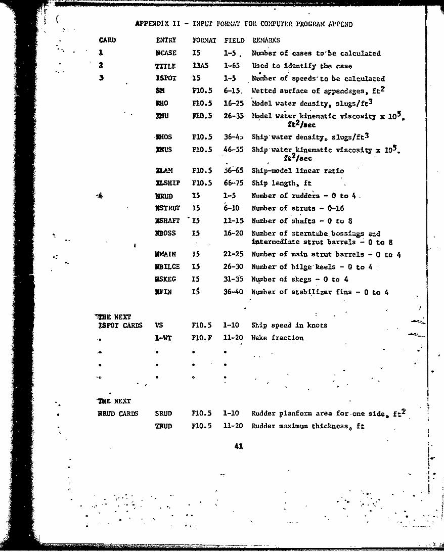
S( *APPENDIX II - INP'r FORKI•AT FOR COINPUTER PROGRAM APPenD
CARD ENTRY FOnMIAT FIELD RDEMARKS
SNCASE 15 1-5 . Number of cases to-be calculated
2 TITLE 13A5 1-65 Used to identify the case
3 ISPOT 15 1-5 Number of speeds'to be calculated
SF10.5 6-15. Wetted surface of appeadages, ft2
Sao F10.5 16-25 'Model water density, slugslft 3
=U F10.5 26-35 Model water kinematic viscosity x 10%ft 2 /sec
-BROS P10.5 36-4z Ship'water density, slugs/ft 3
X4US F10.5 46-55 Ship-water kinematic viscosity x 10g.ft 2 /sec
ZO.A! F10.5 56-65 Ship-model linear ratio
NLSHIP F10.5 66-75 Ship length, ft
hIRUD i5 1-5 Number of rudders - 0 to 4-
NSTRUr 15 6-10 Number of struts - 0-16
ZSRAFr 15 11-15 Number of shafts - 0 to 8
XBOSS 15 16-20 Number of sterntube boss.ngs andIntermediate strut barrels - 0 to 8
.WAIN 15 21-25 Number of main strut barrels - 0 to 4
UBILGE 15 26-30 Number- of bilgekeels - 0 to 4 -
NSKEG 15 31-35 Number of skegs - 0 to 4
UFIN I$ 36-40 Number of stabilizer fins - 0 to 4
IUE NEXTISPOT CARDS VS F10.5 1-10 Ship speed in knots
.. 3-WT F10. F 11-20 Wake fraction
"*0 O 0
* "-. E N E X T
* URUD CARDS SRUD F10.5 1-10 Rudder planform area for-one side. ft2
TRUD F10.5 11-20 Rudder maximum thickncss, ft
o.-
;.1.,t.
•" 0-• • " •'• .oO .

INPUT F0on.RA FOR APPEND (CONT)
CARD ENTRY FORMiAT FIELD PJI2ARKS
CRUD no.5 21-30 Rbidder maximum chord, ft
TBRUD F10.5 31-40 Thickness of trailing edge ofrudder$ ft
SBRUB 110.5 41-50 Projected area of blunt edge* of rudder, ft 2
* *
THE NEXT
NSTRUT CARDS SSTRUr F10.5 1-19 Strut planform area for one side, ft2
TSTRuT fI0.5 11-20 Strut maxiimun thickneos, ft
CSTRUT F10.5 21-30 Strut maximum chord, ft
TBSTPTt. F10.5 .-i1-0 Tnhickness of trailing edge of strutft
SBSTRUJT Fo.5 41-50 Prolectrd area of blunt edge ofOtrut, f02
0 -.
• .-
"THE'NEXT
-FIN CARDS SFIN FI0.5 1-10 Fin planform area for one side, ft
TFIN F10.5 11-20 Fin maximum thlckness, ft
CFIN F10.5 21-30 Fin maximv-n chord, ft
TBFIN F10.5 31-40 ,Thicknes .of trailing edge of fin, ft
SBFIN F1C.5 41-'0 Projected area of blunt edge of strut,• ft 2
42
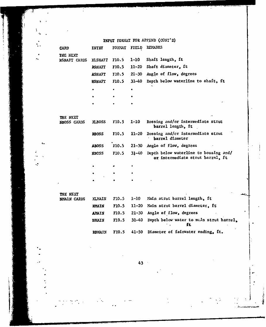
INPUr FORM1AT FOR APP.END (CONT'D)
CARD ENTRY FORIAT FIELD REMARKS
* THE NEXT"NSHAFT CARDS XLSIIAFT Fl0.5 1-10 Shaft length, ft
RSHIAFT F1O.5 11-20 Shaft diameter, ft
ASHAFT F10.5 21-30 Angle of flow, degrees
HSHAFT F10.5 31-40 Depth below waterline to shaft, ft
THE NEXTNBOSS CARDS XLBOSS F10.5 1-10 Bossing and/or intermediate strut
barrel length, ft
RBOSS F10.5 11-20 Bossing and/cr Intermediate strutbarrel diameter
"ABOSS F10.5 21-30 Angle of flow, degrees
HBOSS P1O.5 31-40 Depth below waterline to bossing and/or intermediate strut barrel, ft
THE NEXT
NALZIN CARDS XLNAIN F10.5 1-10 Main strut barrel length, ft
RMAIN F10.5 11-20 Main strut barrel diamerer, ft
AMAIN F10.5 21-30 Angle of flow, degrees
R?1AIN F10.5 31-40 Depth below-water to m;iaLn strut b arrel,ft
RBIAIN F10.5 41-50 Diameter of fairwater ending, ft.
"43
"-
.................... . ......

* -
INPUT FO.IL\T FOR APPEND (CONT'D) (CARD ENTRY FOMMAT FIELD * RENAP5KS
THE NEXTNBILGE CARDS LBILGE F10.5 1-10 Bilge keel length, ft
SBILGE F10.5 11-20 Bilge keel wetted surface ft2
(as described in text)
"THE £EXTNSKEG CARDS LSKEG F10.5 .1-10 Skeg length,, ft
SSKEG F10.5 11-20 Skeg wetted surface, ft 2
.(as described in text)
_ (iL .
START THE NEXT CASE BEGINNING WITH CARD #2
4
i.
°"Ii " Q
449I g 0 "

APPENDIX III - OUTPUT
The output formats of "Append" have been written so as to give the
user detailed information about the drag 'of his appendages. First, the
drag cozponents of each individual appendage are printed out, this includes
the speed-length ratio based on the length of the hull and the local
Reynolds number. Next,.the total calculated frictional resistance components
are printed and finally, the total.calculated viscous resistance is printed.
The program will output the above information for both the model and the
full-scale appendages.
f -
45" '

j J
.4 Q j a a a c a 0a C a c a a a c4 a a
CmN FN piN 0 (I - . -)f m m -. m-l' -I*n -Mi -I -0 .- r) l m -fl00o 0 0 0 0 00 0 0 0 003 00 00T ý 00 00 00 00 0 00 0
WI- I LII WI I-I .i4. ILI I-LI, I-U .1I ).. 11.L 1L ti W I - I-L LI tiJ~ Utam- 40 CU 0- Mcl 00 0atA LnF -0D j 0 o. -m - NC w m4 Ff0i O- 41 Do 1V.0Q t-f
C ~ ~ ~ ~ ~ ~ ~ ~ ~ ~ ~ m -IN o0 Q0.. fnll F-I I~CiIo~O N -l N 0 11 - 1. -
UP NC I- F0 o (5- N Vi IC l- ~ f.. U -l F O M F 0 A
. . . . . . .. . . . . . . . . . . . . . . . . . .
FN 0 U nf n.l
-~~~~I % . -. . . . . . . 1a i . -. C it .1 a *a ..
D. 00 00 00 50 00 o0 00 00 0o 0 o0 o 00 C, 0 C, 00 0In U. t I ',tt L. W ,w ,W L .1 Ia i i1 , 1 . Ww .i*OS it i Ik I, I* W, ito W ui
N- f fn 44 t-0 04 to - FN 40 .0 0-21 f-- LN CC) MN IN D0 -0- P-4 NC I-- C
Li i N ri A l- M-i Ni- N'.- Nl Nl- N'. N 4NN N')-. NN N Nf N m- N- Alf N N N N FmUN mmE N NOo oo 00o 0I0C 00 00 ID1>o0 00 00 00 00 00 00 00 o 0 0 o0 1oo0 C. C0 00 o
w w w I I I-I I-I W L, L I-I wI II I-L Ili I-I I-I I-I I-tII- al in 4 m N m mF- CV F-N o-C w- Inw n- - 4. 0-f n. oC F4 Inn F-I MO mN 41 F--s
I- 'ON 24 N1F 0-n mm- -- m-0 F-2 1V NF ^I. rn 1- cc0 N1 40 -N -'0 C0. Ml -- Inf o3 n N 0 ~ -00 -4 N MO - 0 - 'O F-f w %A
-0., W* aý %11 M : :CN % INMN MN Nn 7nf1 n4 M0 F-A M~ 0,? OF- ?F Q.. 4+ 00 -&fWO --- - - - -
.4 mU FUN FUN F1 u N FN FUN C- N AJAu N FUN FUN FU N AlN FU gmN FU FU FU FUN gmcc 00 o 0 0 .C 0 00 00 0 c 00 0 00 00 00 C. 0 00 o 0 0 0 0o 00 00 00
MV 1 N M w 0.N 1~ 0- If MO 1-f *M OF O# * NO * a
I- In- t:f tV' M-I 00 0- N-I w0 w-0 wi F-I w. 0w. W 0 1 -IF 0-- %L - 00 b Infi
- f-f4 oI' FuN FU FUN FU FU FUN FU N -N N - f% 4. -M c f .. f o.f t
a9 a9 0ý P. M NO- 8 0-4 F-C tp u. I rN NC L"' r-a NO MIoý - LP0 r- m. 'ONý F-f 0 1- t 01 .-.C C,-1 C. c n' on- 0 t o FT ) a 0 00 ofF 0 .o o- - - - - - - - --00.--oNd-.o No0a w wt at j Wl U A wl wa wt i LW ,* w w w wt
La 0I , S tr ýo2- w4 mm e u n. L 3 C
F- 00 CO C 0 04 0 0 0 0 0 0 001 C 00 00 4 00 00 0 00 0V) 0 .9 7.0 , . .a. *4 ** a . *aa ta t
- 0w II I- I- wI U-I WI WI I- w. I-I wI I-I. U3 I-I I- i W-I I-ti -. I-I I-L I-iU) U 00 'V 44 MO N- m 0- F-- MCN. V.nF- Mp FUOjN .0 00 cc F-- C40 -*0 0- CI-
1.4 f - -C MN 03 Nc In- 0-Cn - F-().a IO- MOr .0.0 o 0 u- 1 .0. C o
I- .- A- W. -- -Q - FUN FUN FUN I"J FUN FUN P-N MO MC TO OD' CO 47 0 00
44

0z 0C 0- 0..0- *. O 0~ O C).- 0 -0- 0- D.- C3 0 C .-1 ~ 0 0X OX IX o1 9 1 x X O xX 0O x 0X O x OaX C x CI x X C) _
0a V 20 na) I n AV XVI tV 2V WV x~f In x w x In 1. w IaIn 4ann1 M1 m1 (1 m. N NJ N N NNI N N N N NIIj (Cm I Nl JN N N N(vN NN e NN
44 w.L wW 3. L .J wI. L.3. 1.1 w I.Jww .L 1 I.JbJ t.JL W w WI~ .1. WW*J w W. W .W* W, Ii 1 1.1Wtý6*I.- ml( 0. 0Ol 0-. a l ý o00 n. 0C t- c81 Q1. o 00 OLA. aV C% -1- Nr4 n -.
0 .N in 11 ola w mN NO OW 1- V, a 0 01 gN .04 4o .01 081 NrC
.04 l .09 t.O ID CP. 0a N~- - (A.( NN N N NI, N~l 1'
aIn49
13 4 4o 40 40 40 4c 4o 4c 40 40a 40 40c 4c040 4o 4. -4-wa c a cc a . c o* a c cc c S* c a c T cc a c o* a*
ft 3W* L 1*1 W ' L 1 .81 W W J L. ' *1 31 W LW ILA LW' 1* W LW LAW; .W' I 'A 'AlJ LW LX3 o1 a - m- aN a00 mý a1 f-0 - m1 u3'- o- cc- m m 0-Z (10 m N o atv e- 00 0f. 0 .'D_ NO 04 c0 04; flU P 401 N 4 NZ 40 c 0a 40c N N F. '' 1- N
r2~1 W4 00 .' .1 0- 0 : %1 1- _. n ItO 0 0 C IN 00 1)? 10 .1. ON &i.
fu eN - lI 411 N a (1 1*1 m11 4.m0o 410 41 113 In A co b c 00 .0- tN r, a.
in w.w w wWwaLaw LAW LAW 11W uAW LAW w.u1w LAW LII 3.LI WI LAw td. wAL '1W 1A.J w,. LSL.I&A Pc. n~( 48 m 0 40 & .j N .w -. 0 40 a 1. In 31 818 o0 00 mm.- cc- c0 .0 -D
fu 13 1-I. N m Ni N- NM M 19 co0 n01 4 00 fiN 0D1, . 00 NiO 00 4.0 NO -4 0.D cc
w Wa~ W .11W LW t.W lA W W LJ WIL LIL LAW LW LAW L W LW LA W W W L III LAW LW LILa.7 an 4 10 ;-F o0 P.m or ý- &0 o 1/ n 0 .o .0 40 !! C.: -r m N m1 c -C 2 ( t ,c
J lu1 w 01 000 00 4 m0 o a~ o4 oN m0 c- N n( W N .Oo 44
r. c w m m m m -IM-
-c mg M1 I. mg. m- n1 z1 mg. N N- N N1u eq N NCAN (11 tN (1)N (vN (V r.J (v. N N A ('uIN_j a. o. a, a. a. ao ac ao C. a. a. a. a. a. a. a. a' a. a.oT
ILI w, L.W 131 Lw w31 L W, It 3 w Lww, LAW w,.b LAWi L3 LW, 3L. LAW WI. 13.1.1 1.1 w w, L1% $_ N4 0a.. 44 =0 0 4 113( mnl 40 e 1 z 1( ON 4- n( w4 fC ao Ic 1- w
D f M 00 MA cN M0 @1- 031301 NO 1- =N .(14 0 M-- 40D 00 ww ma-
to J 1 911 .0 .0 .- *1 - - - - - - - - - N- N-* . *N N
t4 0. ft 40 W 0 4 0 40 4 I0 N 4w 40 m 4c 4r 4 0440 a40LO o 4 m 0 an- anle .
cc G4 i. ... .. . %. . . .* * * * * * ** *
LLW Al . LI LA W L13J I L W W13 .131 LW AW LAU:W ULAW 6AW UJW t.JW L 13 11 W LA LAW W-a..u-P_ 1-. 4n (1- -rF NV 4W a, oW(- 1-0 -- n N 04 .1 f-0 (1- Ol tN. -- ' GN>t nA nN orn cc FIN 0.00 (1.1- 0N N (1-1 -04 01- o' -f 00 00 m00P c'
44

* i a- 01 aX 01 oly CX ~ X O L O x L O X O
C- x 0. X: X m. 0.. x x c-. C. xN aJ XN 0N xE N xN 0x
M4 M41 fn1 m41 M.1 m4~ m4L 14W ^j1. N41 N41 14.1 141. mL t4J1 ew1. 141. Cm. ~t 4
g- 03 .0 I-0 x0 C,1 0. .0? .4 Lnli 0 .t -N v? 71 V 0 (IC /I/ N C 0 04 Q'.(D 034 oco m- 1 0 w .- 44 0 00 c- I-.tn m'- 0 ý : 0 00, A, c 0 . P. 0, 0C. f0
M 4 m0 LAc. A0 '04 ,-0 4 P N V0. 1-, ZU c0 ao 11.. 0- -el J000
ON 40 4I1 .0. 04, Mf fn el0 'n
00 O ý 0 00 Q0 00 00 0 00 0, 00 00 0 0 0 0 0 0
C7 40 40 O 40 40 40 40 4- - .. f.' . 0 - - 0.- 40 T0C. 1.0LI 00 00 02 0 CC -0 0 0 0 t 00 0a 00 v0 00 '70 C 40 CC0.0 0-0
CX w41 W,1 'l t UW I ,L W, W,1 I41 141. ti. 41 141. "11 L4. 141. tiL~ 1.11 .11 W.11 14 1. l I LOJLvi co~ 1-0 N 'J 6111 0. 00 W z1-(j' -0 in.- in1 4 0 W 11. 0- 010 0.0 - t 1-0 f .-. 0 -114 -1rj o- 0 4 40 N 'NO 0 M 04 co -w0 inC P 4N o4! m .% . NO n0 in- a 0 N -i 0? 00 WN.
(x 0 OW 4m VII '. 0. 6- 0.. 0- - . .N - . N N
14 4-* 4. 40 4 0 4 N0 N0 el M0 4e M0 40n 40 40 04 40
IA w.1 141 1.11 141. 11 11 .1 w I 1.1. LII. 1 .JL ,Ii .110 '1' 1.11 1.14 .1) Il 1.414 141 1. 11 Ili .1In 0- (.00. .0 0 ý4 CC0 N. a00-D 04 N 'U 4--l .w 11 m1 t-. 01. KN7-. ~0
co cO VN IO ON 1-,I 0.0 04 g4 0-1 0- 1-0 t 4 00 No :- 0 n -. 1
-. 0 -10. - - (3I N-. GoJ- N.- NNl M NN On N 40 N 0" M n- M4
40 00 0 00 -I- C> C 0-. C,~ - .. 0-. O- . ~ 0'
04I (V 0 - Do.- E .0 - -' . ' N- N- N- (CI ('.1. AN MN uOr ro N t-N C04 Va
C: 6.1 o '
.4 00 00 0u 00 M0 00 00 0; ' a0 00 0 0 Z m0 00 00 I o0 00 w C -a
4 o 40 4 2a a 2, -Y 'a I -t 0 1 -a 0 -1, 1-0 a? a. T-0 I. . 7-0 1-01414 C - =.1 6.1. 1.11 141. 1 4W -0 1 141 141 T.1. 1.1. ?4. 141 401 141 T 41 14. .1.
71~ ~~~ 6- (*u - 1. 0.. (01 4 1 L-- *11 0# 0 O 1- . 0 0 '4 00 NVI ( C,1 40. 0L N n m00. Nm Or m- m- n0 C0O , C). 40 NO m' 1--- n mi'4 00L. .7b 44 0 ... 0 0M 4. 0 0 - 0-. -00 :; 40 z0 41/ 0C -0 ON 00 A, ' N n"
cc w C> Nl '0.1 -ml .4 00 0 4' N 11 04 000 20.n C:0 1(0 a, '. 0 0 .
04
cx C6 CO C C0 0. C. CO 00 0 0 N 0 Al 4 0a 00 0 0 00 0VI I~ 4 I ~* 14 ~ ~I '. ow * ý PI O.C. . . *o a N
- ~ ~ ~ ~ t W 14i. V)J 11 1414 .1 .1 ?1.3 P .11 P .31 14o cc1. 41o co11 141 Cc1 0a1 14. 11
44

w CL &Li 6 6 ILt L. .. af b wf CLf w 0 M.C W. OL~ L a. Lif 0. wOm. m. L a. W ra. CL~ i..oCL
cx mx co x acr a:L c w ow owx ow oo oxv ow ox or c cx c cX& Tw ~T m~ xr 2i xi. v~ x i 7 1 ~ 7 ~ 1 ') 1 ~ f x L4 7 :) 2) xii w w 7 xvr iuPall N I (LiP (N N PNN ), NPn, NP m iN A P l N n mr N P AJt' N-ft n,.P (I-t fu-P
4 WIS. li W w WI. JW w,. L, i I.' uL.. w i. Liw L w 1 1.-L Li. * w,. itJ.. i..L t! W u4 ~ Lii. 1WIe O- 9ti' w 0 Cw N t0 '04 P4 a m w~ aO t-4 40 o C. w.U m. w' tN Pow 4"
a .ý in A 4A t l - c
PaN Pcll m I N 4Pt.1 4 r) u% 't '04 & '-4 P- ut CC. a 9 cc0 a w O
a 00 Cl > O a0 00 0 0 C. 10 00 00e 00 00 C .0 00 00 o i 0ýT 0 00oS * I . 9 . 9 . S * * S. 1. .. I* . 9 I f . S.it swI. I wJ w ll b L " , J WI.Ll w, w Ll t..I. w,~ w,~ bw b w, .LILw, Li ll.)' L. .)L 1,1 4 hlow t bI') LLt.)ill lto in 0 M 3M0 N r- r.C 9-it- M- It o t 7.1- LI t'v.~ - ? v4 in 't C6t. -D - I-( .I0 o m0Li w0 o N 40, 'D0 a ' o~ Ut 00 0'- N NP 01 - -0 .)'D Ofl '-D 'o0C G! ''in 44cr.
W-) MN(I m'N 4m1 lon innt D4 9- 4 w~ 0 4 w. ,N a-' - w w N w.r .. p.
N Na NP NP) N P) NP NliN NP A NmP) N f N( NP NI N c. vM. fu AIN ,-. 6) Al .N t-o o Co o0 00 0o 00 o C 0 00 o Gt 00 0 0 C C 0 00 00 1 0 0 0 0
6.0LOUI.. tNw DI C'31 W P MP 4t MUt4n C &f 04 P- t- f-U r, t. 01 j-9 W. L,-0
z
c- . -P 0o CO lo c o C oC 4C C CO c Dco ac CO OC C, C O CC CC CO c o cCal 4 t * * * * * 4* 4 *a 44 *4 4 * 4ý t. 44 44 4* 44
wI Z -0 m0 00 *.- mm0 ma.. Nii 4P P30 Pt- in~ tO m- ~N - N4 c-
to in- to.P U%0 ittn 0.0 DID- NO ItO r- C' OP t -'D w9 Cct wC 440 0. &' -0
a4h Ct4 O9t tO9 904 z 9-9 9-9 z;9- 00 99 00 00~ cý11, -1
44 C: CC to wl &c o Mo oo c o a c c. 'u.C C~ c
40 -- it')' 0t 44 %0 IP l-. -- £0 % CO O C P cI FInOn t Lin) '0'D '0.D0 D 4.0 99 P- r. 00 0 0o m 0- - - -
Li -. 49
CL,0 wa CL 0 w 40 M 14x 0. L.. (16 . I-0 CL t.0. L.,OM Inj. M itý. !... w0. La.C Ul CL WO. LO. rl w0 07 0- .c" 0.- 0-' C 7-' 07. 0" c " 0'0 0'- 07- 07- c" C- c Co70 7 0 a', 0 w10 V Ov' 0r0 Ox. 10 0v 06. Xv' w0 0 .
*4'J M N NW N O f NW NW tv fu N(4f N tv N lJ NW f UN Cm (-V ^'. .'. 1I -0 "0 '00~~~ ~ 00CI0 0 0 C *0 0 010 C,0 0>0 00 0 0 00 0 0 0
I. a* . I .* a~~ ' ** ~ * 10 C., I' 0, 7*b* *4 -1W 4 bun wJ wi. w41 win L.'w L w.1 w4 141 w41 w41 w41 wW 1.31 141 w 1L..ww ww w ,W jw wu
1 N- 4100. 0 < . 0.m m4 r N 0 m -0- -c c0 mC Co <t' r- I'-. P.? - 'c - .: C" C'P F P'.0#ru k n-l; -Ctý aJ:U It- o- L. Nt It- c. a, - C.. t- cc ; "I. r-- m0 '. 0 t c c CNi 00' 0:- a 0
uW C4 u 40 r 10 t F, '04 '04 P'1f 0, 4 iC,- 0--
.d 1- -' .-. 0-' 0.. 0.. N. N.- -' W N NN Nt NN Na N "N (4W Nt t'Icc 0 00 0 0. 0 00 0 00 00. 0 0 00 00 00 0 00 00 00ý 001
Ui w41 11 w w ww 141 1. I I I 141 Wi. wo1 14W LW 141 14W W41 'I'. 4W ia t* 4,i. , ~ W,.1 1.*atr' Il' r- = 0'?r- ae- -'' Q (4 * 4 01 N' W-0 C,. z ; 0 a m rlO ' 0 ,N .2'1 4 - a4 'c N'.-W1 '0m 4 4 o, m0 0 '- 2' .- V o tA T.4. 0.1 e_ V,4 X'- k.1(' ý' 01 ' J kA3.
*~. 4" m14 0 0 .0 C. 0' 0. " '1 OW '30 0- W " N D1 'l-
ON utO 0 (Y- 6 ; r go L'I o'a -1 '0 -1' - 0 .. co M.. N0 nO N O NOm NO m C
0u (Y c N ( NW NWf N p NW N4 r w N NW N r N ( ( NW WNi NW cu - JlS)N v 4 N ;7 (v fu 4*00 00 00 00 C0 00 a0 00 00 0 0 001 00 C0 0
V) P. w11 141 LLl.1. (.31 u41 W, q. .14W , i W 141 1.. Li. tW mu.1t, W W L' l . Li. hi. Llw t14. U:i~1.1 u .0 4 a ýO Cal ,'- o c33. -'0 Li' rP 0.0 (N W3' N O a, 04 Q. .0 02 PN i-Aa0 -. 40P C! 0.- 4-' O' ul1'. Nc 00 AC. Na 00M C'- NI tn -c . (V4 1(n" 00 N3 0.0
L.- . * * ...... ... ......... ný. . ... I. ."t...NlA- NW C -a4 OC lN -ZN 40 Cl 0 F)0-2 '04 'C 4 t-( tft -' 00 CC 0'aC 0?t - 11' - CC -. 01 C
0
1= 0 0 0 O ID C00 c0 cC 0ý 00 00 CC <0 c o 0 100 c00 10 c 0
' '-. 0 ~ ' lJ.. 141 *11. 14 W 11 4 4 W.. WW t11 14 14 t~.J 14 11 14 .1 44W* z 0.0 - N 0- 0 a- m" 00 lo- 00 ac 1" 4 4i m40 "'0 W 0 0. C. N
a W 44 '. 0'C ... MMw0 IjIi "'? -0 .- :! 00 m 4 p -? 0o N. z 0 .0* 0 0
64 pi1 r NN dur f W' 00e lt, r .0m m0 fn 0C 447 44 44 'S14 ir-4 0U 113* WkI3 0 t A n13 '0-0 '0'C
0.0
a 141 .141. 141 141 r 41 m 1.11 C N aO L Pi.J 141.3 LiW-144 WWW1414 Wcc.34 1.4 41 1 14 - &.. a.30 0 '-1 - 44 00 ooP 00W m0 a~' NW pi' C.. N-4 ." -- (1' 0 N' 0
in 11111 Wn '00 '0.0 '0.D 0 p"aI- 9'.?- (oto0 Oa a0 40 00
.50

-1 .1 4 -A j - i a a J .5 4 .1 .5 a i j j a i au. a- c. CL wIL U a .W .O.. W. CL w.L-.L I CL-. 06. 1- a-. a- w. w. C- a. m a-
0 x ax o0 x x x x xa r r xo xo
0N NUN m R N t( NN SN ( N N NN ( N N N (N fN N NN (UN A N ;; f ftP .f .. ¶ .cc cc 0a 0a a 0 00 400 a00 aC 003 Co 0a 00 00 00 0 0 CC
.j WA. A L AW i.- L W, LAW LAW wA UL LA laW wA wA LA wA LA LW A AW
0 U -O - 'N mn ipS ON LtC P- C -t V4 04 OD. -C Op" 0. 400 C
9- 4. 0 9A C; 0.0 9-4 1; P C 0 PO; ONC .4 j( ..1 9n 1. 91-S VO N
0( '0 o.. init C.. C) . -0 0, S. C>94 4f -t 00 C 0 4 0 O fl N
NA - wa r fl n -CA 2N o~ oi- WE 9,0 9-1 9-P n 4 0- LA 040 -- r- -.A c c
*L .- n Lt: 't 9 * * ** 900 14 f IOf 009 0- i 10 0D P0 00D CC MC r) C' N0 00 W0 MC ft M N
4A i-P i-Q -N -~ Mi fu- Nl- N-.- CVc .8.-'v yf ( V NN N. Co.- ft.( (UN NW (N N N m '. C UN Az cua 00 00 00 C00 00 00 00 00 C>T ,0 010 0 0 0.0C 00 0, 0C, 0 C.
ýl. . 0* 0 I. 1* 0. 1* 1, 104 I' 04 1.. 1 .1 1 .4 *w wA LAI LAW LA A A W LW WW .A6 L W w LsW LA LA U AW L w k L wL
M i-S (V9 M3 n9 n.0 nD- &n. 9-4 OC 0e l N-f .. 0 It5 0- In59 No M -'- Co#I &P n0 -- P.4 ,O o- 05 '0- o0 ~.7j O-50 to, Wi--. 9- ONj -.2- n-S m' a Q
0. C:4 ttC i I 1M N MN 1," hIS' 004 044 #1f 0b N .. in c'- i-S ri- WI-S CC
o IA U% 0 0. 00. 00 0. 0 0ýI ý0 00 00 CC of- o 00 00t 00 inP0. 0 P- CO O P-V CýwPr . 14 69 T* T* ., I.* * I' 4 04 4 09 0. 04 04 04 * 04 D o
2 0- LAd LA 0.w LW LA LA LAw W La W LAW L.b ", . LAW Wj LAW ' LASW w jW L.. aW WI tLAWvi LA 4 -S ~ O m -A w 00 S 0i- .1-4 00 r,9 CPP r, m ,0 mI! .. m'( .0 .i- 0' 0- m aoI
4. 3.. i-.. O -AP.0 V,9 .O'.4 U%. 40 0 wn0 w- -N 09 ftSf 0.- m' 0.- p-C " mcc w P4. m 0 0F - 4.4( rN i-O 0% i-S?2 0- V 11 00 WE f.'0 a0' a 0 ONu 00- .-. NO
V.
- 0 w CC 0 00 00 0w wC 00 00 00 00, C , C ,C C , . 1 0 . 0 0 0VS~ ~~~~ al *. . . . . . . ** 9. ** * 9 4 4* .. 49 *
VP Z -04 o 9*n 0. 9- P ý .0W 0 9-4 U5 S C 0 VI-., ( cu S.S. 5'# -O to 0 w.0 40 N 9 'OD , 0in. fn '04 WE vl' cc go4 li(i- lii- &j.. & n ft EN m3. e5. 4Nis O1-A LA 1is~. ou -- o - -E . Won %-- 0: 'll. f0 o pp Q - i-N W --
LAaf 01 0U to N 101 N 4-515 P- I-S t-'- f- i- i-Sf CD 44 44 4p 0-1 0801 in 0W Wn
a5

IAJ Lie. W - W . W a. Wa CL . 1..a W4 Wif CLf Wif a a M2 Lf Ilif CL Wa W~ L.tý & wa a (3 a a0 - C0- 0.' o- 0'- a. 0a a'-
4~~ O0 x x x g g1 r or or x; or o x r)an _xn Z4n x ~ %~n xU V)S x~ %')Zn X0f X~ Vn x~ Z0f Wn x Zx x
x0 fu 00 N0 r0 -u N- - - - - E I.-.m1 -ME 14r M~ ME 'I00D a0 10 c0 00 0,0, 00 00 00 0 00 0 00 0 00 0 00 0 0 0
I4 ** 8 I. * 1 . 8 1 * * *. S. Io .. a* , . . S I. loU, W W.W 11 ii W. W J, . 14W LW "I LJ 14 W 1ww .JL U JWL 141 wI. 1W 14WW L.b Lli iww
4 .g 4.0 o., 8 0 , -. 0L r-a 'Cii 00 00 .0. 00ý a. i 0I( w7 mf 0 '(J O- (4 CU w. AW m '.00 L'n P 4 t-0 Of- fQ N 04 m O 4' 0 a-. m( N-. Li
V)0 .70m liii .0w Ow "-'E wW (v0 0w w ý 0w'0 w*- 'O00 0 '-.w ('D m 0 w -- 'am Nm 04 .0 w aC
_j ., I0 . 4 . *qU I0. O' --L # *t l.- E . N .,j C~ii NO 1 ' *i *
Li cC r .cr - K .
CL %
Ln WL L. Ll. W- "1 ** W* W, W. .. Ll. W* Ili * * * *W **........- 8 0 a 8w WW UW LiW LiW W4 141 I.IJ 1W .W 1W 11 JJ1 W WI. C"' WdlL
a o r--. OdE 44 - 4W n0 m '( le 0 N. N 'r a ,* a ONN . t-r- (0 4 ' 0 1-0 Ito M u 0' No 4-Li 1ý t1' (.0 .1f CC 4c '* 'rL a 0.3 U'( CýC oo- f-. o. -O4 aI~ LIS Z C'. 0,0 a-.o
C0 L n C W 0N 10El .010J (-10 Q 'f 00 rN 4. 'OW 0-f mw me. 01. * '4 0-
a52

a 00 CC C TCTCC0v0**eCCc070eacw~~~ Lsm s1a a,.,l ILI,, asa Ws
Z -kiL lWI*.I*.k i-w&JLQh~*0a -. N 'e DI wm£N 4 no ýD CC-U. 'ON
In ~ ~ ~ 4 a 0. 0,D'. ~ ar - n r Cr fC r C ri % N - M e. -a N N 00 r'0~~ ~~ Sn * t. M a _N 4 .0 a C mm r- .. ....
* ftj
031
a .l . a **. 0 a 0 1** * 42 w 0 4 0C.CpC_0 ,=- 04 a 0j -0 0 0 10 CP C. C, 0 D C, 40a. Cl4 o0 4 3C 00 34 C .0
L.0 0 0.c c a c o a a a a ~ a
ai CP *~p MY * f~ . 2 *% mtM 1.0 O*m 4 0 * *
in40.00 .0 w
U 4
P. NCO 41&lNWC.O fU 4C
W I.C ZP o -. D0
L0 C
Cu 0.o C. . a0 g @ O S * C,= la 0* , p-0C 4 S
inL.&C y nt -a mU Cc lV. I,-' .ý0C -4C3 toNMnMM W% D-
In- C
toa01Z
P. ". a- C - N N ft N. CU- erllPMg- r. MoaWnoAiCW CC .oN 4 C
ft wV,. N a*** * * 0 5 00,m1 0 In & 4 N P
0 4kup V) -- fi A- oQ N ,a 5 q., ,9P.- zNNNMMf la Vr r 24S- nMW2thi0 z S
(LN 2mm8-m 44SWw nL r, . DO -P
4uwc c co c e occ c o oa. c o co o o c oc c c c o
It 2 coc~~occ ccac a co oc53

000000...00.0 .r.r'.- <7 CY CD C) 0 034 0- lC 0 0ý c, ID 4ur C3 0 0
hio C 4JL. V, .J..~4 M (1W -V. r ,4 M.g Lic ^i iLJ.JL M
fl o 0~f if iI rl 4 4 7 4 4 .~4 4 44 4r 4 4 7 4400 CO 00 a 000c0kCD0 0 Of: 000 0
.01 Ini 0m i; )C 4. C. n 0 f-. r -t 4 l - I : '
* a 0
it i
C 0 0 * *0. 0 0 0 * o o 0 .
OR 00Z0 00 00 000V70
I C) mflmifltif r:a flhmflr r)Menme Jnfr (I ll~iIrl~ )c
CL tz~~J~Liwý ,u wW Wi Wa ww w ww wUWw
4 L 0 tt ýcC C 4 aru w.~ ' Irm M,;. NC . t C2Li '
* @.D .-. a-.-.-= 4=flF) 4u 40c= C, QIt 42C 0a4
* ~ ~ ~ ~ .Aa1Jt. J.Z N 4i~ CP Ln %0 (410 7 0 O l -T1.. 0 - 7r mMVc >
grwm C. W.i a C-0 z;JL.JLJML MD.JoC c Liý LJLULt4
w~ 4D 1= C -.N r0 C ir ND C3 C0 0 C) > <' 0 I J'Oo ':' ai C30
ef 4nNw~ cc1 t ) cOr-lfI c C. ?Cc
- -, - icru4mmc
m 0 0lC l lrlC)C)mm~~~~~~~ 04 CU'J CN C10c) 4Dlllffr C3 r Cit 'DO rir't
fha ca N0 0 C 00m'0, (01 CO'o :-. < m o wO:OO
* ~ ~ ~ ~ ~ ~ ~ ~ c 7: IT 4l 10 0I' 40 'C i'ýO- 0 CDC ( C; '.3-w a, Cl %p C nf ýr D. ) 0 c
00 ý 00 0 3 000 000 00~ 0 0 0000 0 0 000
CD- -c La VLi C3J~ 'TLi r t oL Li~ <auý ccLI L ca r4~ L ý Ca ri ': L L
I,- _( 0C4
ý0C t?--_ C '. t-.' D O. V. D
.h. ~ ~ ~ ~ ~ 3 Co C. (1.0 (U4 0Ji ýiot 00.) 0f' l 040
g in
b,- co r a C c -s -- Ini0 %L- -7ti mr-%- C3,7 01( 1 3 0(U (0 ( 43 0C. N
VILn- 000000000 000000 0!00:
4k ~ Vý0. 4~ 4D In <40Cý n.A.C
03 3JN'0 ro m 1((( Cl1f C; 9: > 2ClC 0cC.' <,'o0CIa

REFERENCESU
1. Mandel, P., "Some Hydrodynamic Aspects of Appendage Drag," Transactions,Society of Naval Architects and Marine Engineers, Volume 61 (1953).
2. Clement, E.P., "Scale Effect on the Drag of a Typical Set of Planing_Boat Appendages," David Taylor Model Basin Report 1165 (Aug 1957).
3. Radler, J.B., "The Prediction of Power Performance on Planing Craft,"Transactions, Society of Naval Architects and Marine Engineers, Volume 74(1966).
S4. Moore, W.L., "Some Theoretical and Experimental Results on PressureInteraction of Hydrofoil Boat Components," David Taylor Model Basin Report2131 (Nov 1965).
5. Cheng, H.M., et al., "Analysis of Right-Angle Drive Propulsion System,"
Paper No. 20, Society of Naval Architects and Marine Engineers DiamondJubilee International Meeting, New York (Jun 1968).
6. Smith, A.M.O., and Hess, J.L., "Calculations of Non-Lifting PotentialFlow about Arbitrary Three Dimensional Bodies," Journal of Ship Research,Volume 8, Number 20 (Sep 1964).
7. Denny, S.B., "Applicability of the Douglass Computer Program to Hull
Pressure Problems," David Taylor Model Basin Report 1786 (Oct 1963).
8. Schoenherr, K.E., "Resistance of Flat Plates Moving Through a Fluid,"
Transactions, Society of Naval Architects and Marine Engineers, Volume 40(1932).
9. Hama, F. R., "Boundary-Layer Cbaracteristcs for Smooth and Rough Surfaces,"Transactions, Society of Naval Architects and Marine Engineers, Volume 62(1954).
10. Whicker, L.F., and Fehlner, L.F., "Free-Stream Characteristics of a'Family of Low-Aspect-Ratio, All Movable Control Surfaces for Applicationto Ship Design," David Taylor Model Basin Report 933 (Dec 1958).
U. Hoerner, S.F., "Fluid Dynamic Drag," Published by the Author (1964).
12. "Explanatory Notes for Resistance and Propulsion Data Sheets,"
Society of Naval Architects and Marine Engineers Technical and Research BulletinNumber 1-13 (July 1953).
P
55
A