naval construction and engineering ship design and ...construction naval ship design” is the last...
TRANSCRIPT
Naval Construction and Engineering Ship Design and Technology Symposium
Wednesday, April 30, 2014
Twenty Chimneys Room, MIT Stratton Student Center
0800 - 0845 Registration and continental breakfast 0845 - 0920 Welcome and Opening Remarks - Prof. Michael Triantafyllou, Director, Center for Ocean Engineering
- CAPT Mark Thomas, 2N Curriculum Officer - Prof. John Leonard, Area Head, Ocean Science and Engineering 0920 - 1010 Student Design Project Briefs
- LCS Heavy Lift Tender Conversion LT Jeff White, LT Matt Williams, LT Ryan Zachar
- Fuel-Efficient Destroyer, DDG(X) LCDR Douglas Jonart, LT Aaron Dobson, LT Adam Jones
1010 - 1030 Break and Poster Sessions (featuring student theses and projects) 1030 - 1050 Research Brief: Prof. Ron Ballinger, LCDR Doug Jonart 1050 - 1140 Student Design Project Briefs - T-AKE Humanitarian Assistance/ Disaster Relief (HA/DR) Conversion
LT Kerry Bosché, LT Ian Campbell, LT Ungtae Lee, LT Vanea Pharr - Special Operations Vessel LT Leon Faison, LT Kyle Miller, LT Kyle Woerner
1140 - 1200 Break and Poster Sessions (featuring student theses and projects) 1200 - 1300 Lunch Buffet and Keynote Address
Rear Admiral David Johnson, PEO Submarines 1300 - 1320 Student Design Project: Whidbey Island Class LSD to SEAL Support Ship Conversion LT Brandy Dixon, LT Matt Strother, LT Kathleen McCoy 1320 – 1405 Research Briefs: Dr. Stefano Brizzolara, LTJG Vasileios Georgiadis, LT Leon Faison 1405 - 1425 Break and Poster Sessions (featuring student theses and projects) 1425 – 1445 Research Brief: Dr. Mike Benjamin, LT Kyle Woerner 1445 - 1515 Student Design Project: Anti-Piracy Combatant
LTJG Vasileios Georgiadis, LT Mark Ewachiw, LT Damian Oslebo
1515 – 1540 Research Brief: Prof. Tomasz Wierzbicki, LT Kyle Miller 1540 – 1600 Wrap-up and concluding remarks 1600 Mission Complete
2
History
In August 1897, the Chief Naval Constructor, Commodore Hichborn requested Massachusetts Institute of Technology to develop and offer a three-year course of study for the professional training of naval constructors. MIT cordially responded to this request and a course of study was agreed upon. The three years of work were designated as the Junior, Senior, and Graduate years. Successful completion of the course led to the Master of Science degree. In 1901, three graduates of the U.S. Naval Academy, Ensigns Ferguson, McEntee, and Spilman, began the course of study under the direction of Professor William Hovgaard. A 1877 graduate of the Danish Naval Academy in Copenhagen, Hovgaard served in the Danish Royal Navy until 1883 when he was sent to the Royal Naval College in Greenwich, England, to study warship construction. He graduated from its three-year course in 1886 and the next year published his first naval book, “Submarine Boats.” In 1901, as a Commander in the Danish Navy, he came to the United States to continue his study of the submarine and was induced by the Secretary of the Navy, John D. Long, to take charge of the new course for naval constructors at MIT. Professor Hovgaard resigned from the Danish Navy as a Captain in 1905. He was head of the new course, designated XIII-A, until 1933 when he retired as a Professor Emeritus. During his years as head of course XIII-A, Professor Hovgaard taught hundreds of Naval officers and authored several widely used textbooks. The Naval Academy graduates sent to MIT for the course officially were attached to the Navy Yard in Charlestown and were registered as regular MIT students. The faculty maintained close relations with the chief constructor in Washington and with the constructors and top civilian staff at the Navy Yard and Fore River Ship and Engine Company in Quincy. This served two purposes: the instruction at MIT was being adapted to the needs of the service, and the faculty could use the work under construction at both yards to illustrate the classroom instruction. The course schedule was arranged to permit the students to spend one afternoon a week at the Navy Yard . The course for naval constructors differed from the regular course XIII studies in that it was more intensive, more advanced, and was focused on warship design. A feature of the course, presented from the beginning, was that it fully immersed students in the various subjects not only with lectures, but with projects and practical assignments designed to provide hands-on experience in drawing, machine tool work, and laboratories. Since 1910, instructors in the XIII-A curriculum have also been commissioned U.S. Navy officers. The first, Professor Henry H. W. Keith, with course XIII-A from 1910-1945, was commissioned a Lieutenant Commander in the Corps of Naval Constructors during WWI. Instructor Harold Larner (1916-1917) also held a naval commission and retired as a Captain. From 1910-1945, Course XIII-A relied on long-term instructors such as Professors Hovgaard (Captain, Danish Navy, 1901-1933), Keith (Captain, USN, 1910-1945), and Rossell (Captain, USN, 1931-1946) to lead the naval construction program. In 1945, the Navy’s Bureau of Ships inaugurated the practice of detailing two active duty officers as professors for relatively short terms (2-3 years). At any given time, one officer would be a trained and experienced naval architect and the other a naval engineer. In January of 2005, the Department of Ocean Engineering merged with the Department of Mechanical Engineering. The Naval Construction and Engineering Program, formerly called XIII-A, is now Course 2N in the Center for Ocean Engineering, Department of Mechanical Engineering.
3
MIT Naval Construction and Engineering Program Description
The graduate program in Naval Construction and Engineering is intended for active duty officers in the U.S. Navy, U.S. Coast Guard and foreign navies who have been designated for specialization in the design, construction, and repair of naval ships. The curriculum prepares Navy, Coast Guard and foreign officers for careers in ship design and construction and is sponsored by Commander, Naval Sea Systems Command. Besides providing the officers a comprehensive education in naval engineering, we emphasize their future roles as advocates for innovation in ship design and acquisition. All officers write a thesis and we endeavor to direct them toward research that supports the needs of the Navy or the Coast Guard. The course of study consists of either a two-year program, which leads to a Master of Science degree in Naval Architecture and Marine Engineering, or a three-year program, which leads to the degree of Naval Engineer. The principal objective of both the two and three-year programs is to provide a broad, graduate level technical education for a career as a professional Naval Engineer with ship orientation. In addition to concentrating on hydrodynamics, structures, and design, the curricula of both programs provide an appreciation for total ship engineering in a manner not covered in mechanical, electrical, structural, nor nuclear engineering. This approach provides an academic background for individuals who will later occupy positions of influence and actively participate in the concept formulation, acquisition, construction/modernization, design, maintenance, or industrial support of large-scale ship system programs. The curriculum emphasizes ship design through a sequence of five subjects. “Projects in New Construction Naval Ship Design” is the last in the sequence of subjects in naval ship design at MIT. This ship design project, along with the graduate thesis, represents the culmination of the three-year Naval Construction and Engineering Program. The ship design project provides each student with the opportunity to develop an original concept design of a naval ship. The project begins during their third summer, continues through the Fall semester and Independent Activities Period and completes in their final Spring semester. The major objectives of the project include: (a) application of their naval architecture and ship design education in a complete concept design process; (b) application of their MIT technical education to at least one area of detailed engineering in this project (e. g., structures, hydrodynamics, signatures); (c) contribution to existing MIT Center for Ocean Engineering design tools; (d) application of at least one new technology and assistance in answering design questions for sponsors. These objectives are the basis for specifying requirements and planning individual projects. There are two active-duty Engineering Duty Officer faculty for the Naval Construction and Engineering program and officers from the U.S., Hellenic, Israeli, Turkish and Canadian navies and U.S. Coast Guard in the program. Officer students are admitted, and Navy faculty members are appointed, through normal MIT procedures. The program is a model of voluntary collaboration for the mutual benefit of MIT and the Navy.
4
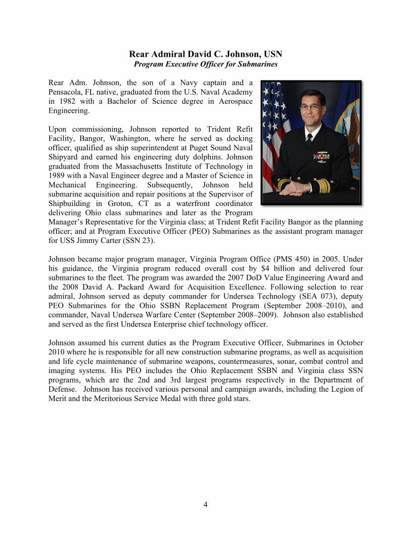
Rear Admiral David C. Johnson, USN Program Executive Officer for Submarines
Rear Adm. Johnson, the son of a Navy captain and a Pensacola, FL native, graduated from the U.S. Naval Academy in 1982 with a Bachelor of Science degree in Aerospace Engineering. Upon commissioning, Johnson reported to Trident Refit Facility, Bangor, Washington, where he served as docking officer, qualified as ship superintendent at Puget Sound Naval Shipyard and earned his engineering duty dolphins. Johnson graduated from the Massachusetts Institute of Technology in 1989 with a Naval Engineer degree and a Master of Science in Mechanical Engineering. Subsequently, Johnson held submarine acquisition and repair positions at the Supervisor of Shipbuilding in Groton, CT as a waterfront coordinator delivering Ohio class submarines and later as the Program Manager’s Representative for the Virginia class; at Trident Refit Facility Bangor as the planning officer; and at Program Executive Officer (PEO) Submarines as the assistant program manager for USS Jimmy Carter (SSN 23). Johnson became major program manager, Virginia Program Office (PMS 450) in 2005. Under his guidance, the Virginia program reduced overall cost by $4 billion and delivered four submarines to the fleet. The program was awarded the 2007 DoD Value Engineering Award and the 2008 David A. Packard Award for Acquisition Excellence. Following selection to rear admiral, Johnson served as deputy commander for Undersea Technology (SEA 073), deputy PEO Submarines for the Ohio SSBN Replacement Program (September 2008–2010), and commander, Naval Undersea Warfare Center (September 2008–2009). Johnson also established and served as the first Undersea Enterprise chief technology officer. Johnson assumed his current duties as the Program Executive Officer, Submarines in October 2010 where he is responsible for all new construction submarine programs, as well as acquisition and life cycle maintenance of submarine weapons, countermeasures, sonar, combat control and imaging systems. His PEO includes the Ohio Replacement SSBN and Virginia class SSN programs, which are the 2nd and 3rd largest programs respectively in the Department of Defense. Johnson has received various personal and campaign awards, including the Legion of Merit and the Meritorious Service Medal with three gold stars.
5
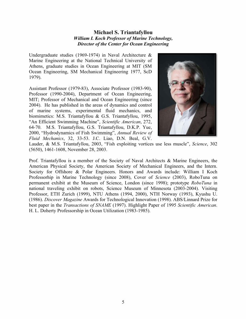
Michael S. Triantafyllou William I. Koch Professor of Marine Technology,
Director of the Center for Ocean Engineering Undergraduate studies (1969-1974) in Naval Architecture & Marine Engineering at the National Technical University of Athens, graduate studies in Ocean Engineering at MIT (SM Ocean Engineering, SM Mechanical Engineering 1977, ScD 1979).
Assistant Professor (1979-83), Associate Professor (1983-90), Professor (1990-2004), Department of Ocean Engineering, MIT; Professor of Mechanical and Ocean Engineering (since 2004). He has published in the areas of dynamics and control of marine systems, experimental fluid mechanics, and biomimetics: M.S. Triantafyllou & G.S. Triantafyllou, 1995, “An Efficient Swimming Machine”, Scientific American, 272, 64-70. M.S. Triantafyllou, G.S. Triantafyllou, D.K.P. Yue, 2000, “Hydrodynamics of Fish Swimming”, Annual Review of Fluid Mechanics, 32, 33-53. J.C. Liao, D.N. Beal, G.V. Lauder, & M.S. Triantafyllou, 2003, “Fish exploiting vortices use less muscle”, Science, 302 (5650), 1461-1608, November 28, 2003.
Prof. Triantafyllou is a member of the Society of Naval Architects & Marine Engineers, the American Physical Society, the American Society of Mechanical Engineers, and the Intern. Society for Offshore & Polar Engineers. Honors and Awards include: William I Koch Professorhip in Marine Technology (since 2008), Cover of Science (2003), RoboTuna on permanent exhibit at the Museum of Science, London (since 1998); prototype RoboTuna in national traveling exhibit on robots, Science Museum of Minnesota (2003-2004). Visiting Professor, ETH Zurich (1999), NTU Athens (1994, 2000), NTH Norway (1993), Kyushu U. (1986). Discover Magazine Awards for Technological Innovation (1998). ABS/Linnard Prize for best paper in the Transactions of SNAME (1997). Highlight Paper of 1995 Scientific American. H. L. Doherty Professorship in Ocean Utilization (1983-1985).
6
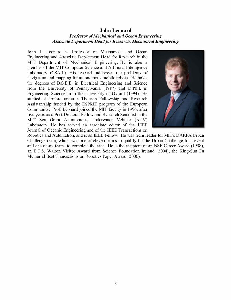
John Leonard Professor of Mechanical and Ocean Engineering
Associate Department Head for Research, Mechanical Engineering John J. Leonard is Professor of Mechanical and Ocean Engineering and Associate Department Head for Research in the MIT Department of Mechanical Engineering. He is also a member of the MIT Computer Science and Artificial Intelligence Laboratory (CSAIL). His research addresses the problems of navigation and mapping for autonomous mobile robots. He holds the degrees of B.S.E.E. in Electrical Engineering and Science from the University of Pennsylvania (1987) and D.Phil. in Engineering Science from the University of Oxford (1994). He studied at Oxford under a Thouron Fellowship and Research Assistantship funded by the ESPRIT program of the European Community. Prof. Leonard joined the MIT faculty in 1996, after five years as a Post-Doctoral Fellow and Research Scientist in the MIT Sea Grant Autonomous Underwater Vehicle (AUV) Laboratory. He has served an associate editor of the IEEE Journal of Oceanic Engineering and of the IEEE Transactions on Robotics and Automation, and is an IEEE Fellow. He was team leader for MIT's DARPA Urban Challenge team, which was one of eleven teams to qualify for the Urban Challenge final event and one of six teams to complete the race. He is the recipient of an NSF Career Award (1998), an E.T.S. Walton Visitor Award from Science Foundation Ireland (2004), the King-Sun Fu Memorial Best Transactions on Robotics Paper Award (2006).
7
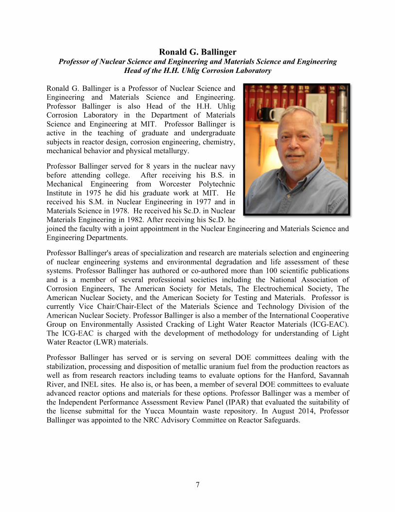
Ronald G. Ballinger Professor of Nuclear Science and Engineering and Materials Science and Engineering
Head of the H.H. Uhlig Corrosion Laboratory Ronald G. Ballinger is a Professor of Nuclear Science and Engineering and Materials Science and Engineering. Professor Ballinger is also Head of the H.H. Uhlig Corrosion Laboratory in the Department of Materials Science and Engineering at MIT. Professor Ballinger is active in the teaching of graduate and undergraduate subjects in reactor design, corrosion engineering, chemistry, mechanical behavior and physical metallurgy.
Professor Ballinger served for 8 years in the nuclear navy before attending college. After receiving his B.S. in Mechanical Engineering from Worcester Polytechnic Institute in 1975 he did his graduate work at MIT. He received his S.M. in Nuclear Engineering in 1977 and in Materials Science in 1978. He received his Sc.D. in Nuclear Materials Engineering in 1982. After receiving his Sc.D. he joined the faculty with a joint appointment in the Nuclear Engineering and Materials Science and Engineering Departments.
Professor Ballinger's areas of specialization and research are materials selection and engineering of nuclear engineering systems and environmental degradation and life assessment of these systems. Professor Ballinger has authored or co-authored more than 100 scientific publications and is a member of several professional societies including the National Association of Corrosion Engineers, The American Society for Metals, The Electrochemical Society, The American Nuclear Society, and the American Society for Testing and Materials. Professor is currently Vice Chair/Chair-Elect of the Materials Science and Technology Division of the American Nuclear Society. Professor Ballinger is also a member of the International Cooperative Group on Environmentally Assisted Cracking of Light Water Reactor Materials (ICG-EAC). The ICG-EAC is charged with the development of methodology for understanding of Light Water Reactor (LWR) materials.
Professor Ballinger has served or is serving on several DOE committees dealing with the stabilization, processing and disposition of metallic uranium fuel from the production reactors as well as from research reactors including teams to evaluate options for the Hanford, Savannah River, and INEL sites. He also is, or has been, a member of several DOE committees to evaluate advanced reactor options and materials for these options. Professor Ballinger was a member of the Independent Performance Assessment Review Panel (IPAR) that evaluated the suitability of the license submittal for the Yucca Mountain waste repository. In August 2014, Professor Ballinger was appointed to the NRC Advisory Committee on Reactor Safeguards.
8
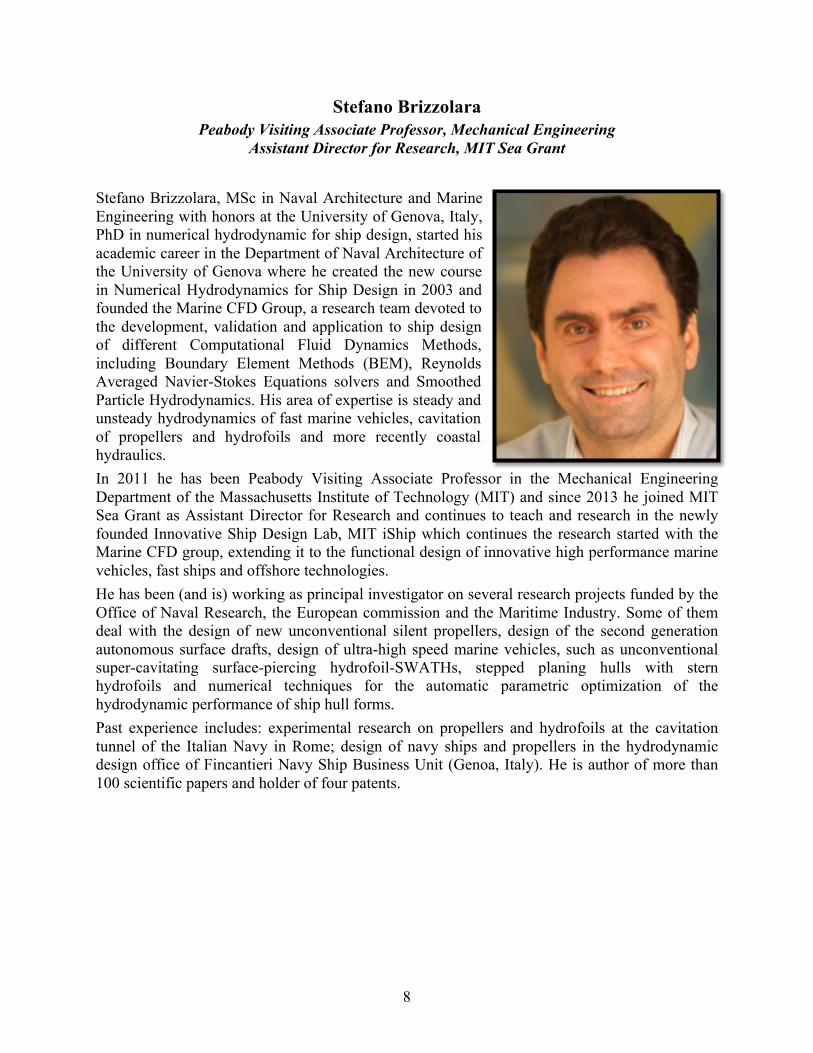
Stefano Brizzolara Peabody Visiting Associate Professor, Mechanical Engineering
Assistant Director for Research, MIT Sea Grant
Stefano Brizzolara, MSc in Naval Architecture and Marine Engineering with honors at the University of Genova, Italy, PhD in numerical hydrodynamic for ship design, started his academic career in the Department of Naval Architecture of the University of Genova where he created the new course in Numerical Hydrodynamics for Ship Design in 2003 and founded the Marine CFD Group, a research team devoted to the development, validation and application to ship design of different Computational Fluid Dynamics Methods, including Boundary Element Methods (BEM), Reynolds Averaged Navier-Stokes Equations solvers and Smoothed Particle Hydrodynamics. His area of expertise is steady and unsteady hydrodynamics of fast marine vehicles, cavitation of propellers and hydrofoils and more recently coastal hydraulics. In 2011 he has been Peabody Visiting Associate Professor in the Mechanical Engineering Department of the Massachusetts Institute of Technology (MIT) and since 2013 he joined MIT Sea Grant as Assistant Director for Research and continues to teach and research in the newly founded Innovative Ship Design Lab, MIT iShip which continues the research started with the Marine CFD group, extending it to the functional design of innovative high performance marine vehicles, fast ships and offshore technologies. He has been (and is) working as principal investigator on several research projects funded by the Office of Naval Research, the European commission and the Maritime Industry. Some of them deal with the design of new unconventional silent propellers, design of the second generation autonomous surface drafts, design of ultra-high speed marine vehicles, such as unconventional super-cavitating surface-piercing hydrofoil-SWATHs, stepped planing hulls with stern hydrofoils and numerical techniques for the automatic parametric optimization of the hydrodynamic performance of ship hull forms. Past experience includes: experimental research on propellers and hydrofoils at the cavitation tunnel of the Italian Navy in Rome; design of navy ships and propellers in the hydrodynamic design office of Fincantieri Navy Ship Business Unit (Genoa, Italy). He is author of more than 100 scientific papers and holder of four patents.
9
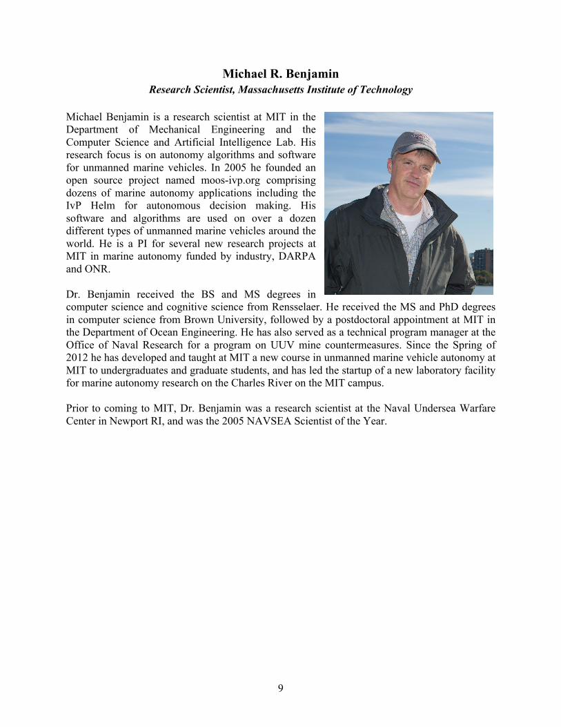
Michael R. Benjamin Research Scientist, Massachusetts Institute of Technology
Michael Benjamin is a research scientist at MIT in the Department of Mechanical Engineering and the Computer Science and Artificial Intelligence Lab. His research focus is on autonomy algorithms and software for unmanned marine vehicles. In 2005 he founded an open source project named moos-ivp.org comprising dozens of marine autonomy applications including the IvP Helm for autonomous decision making. His software and algorithms are used on over a dozen different types of unmanned marine vehicles around the world. He is a PI for several new research projects at MIT in marine autonomy funded by industry, DARPA and ONR. Dr. Benjamin received the BS and MS degrees in computer science and cognitive science from Rensselaer. He received the MS and PhD degrees in computer science from Brown University, followed by a postdoctoral appointment at MIT in the Department of Ocean Engineering. He has also served as a technical program manager at the Office of Naval Research for a program on UUV mine countermeasures. Since the Spring of 2012 he has developed and taught at MIT a new course in unmanned marine vehicle autonomy at MIT to undergraduates and graduate students, and has led the startup of a new laboratory facility for marine autonomy research on the Charles River on the MIT campus. Prior to coming to MIT, Dr. Benjamin was a research scientist at the Naval Undersea Warfare Center in Newport RI, and was the 2005 NAVSEA Scientist of the Year.
10
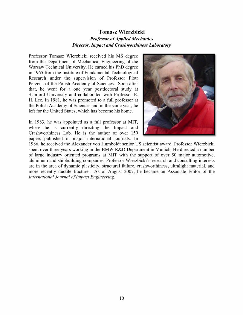
Tomasz Wierzbicki Professor of Applied Mechanics
Director, Impact and Crashworthiness Laboratory
Professor Tomasz Wierzbicki received his MS degree from the Department of Mechanical Engineering of the Warsaw Technical University. He earned his PhD degree in 1965 from the Institute of Fundamental Technological Research under the supervision of Professor Piotr Perzena of the Polish Academy of Sciences. Soon after that, he went for a one year postdoctoral study at Stanford University and collaborated with Professor E. H. Lee. In 1981, he was promoted to a full professor at the Polish Academy of Sciences and in the same year, he left for the United States, which has become his home. In 1983, he was appointed as a full professor at MIT, where he is currently directing the Impact and Crashworthiness Lab. He is the author of over 150 papers published in major international journals. In 1986, he received the Alexander von Humboldt senior US scientist award. Professor Wierzbicki spent over three years working in the BMW R&D Department in Munich. He directed a number of large industry oriented programs at MIT with the support of over 50 major automotive, aluminum and shipbuilding companies. Professor Wierzbicki’s research and consulting interests are in the area of dynamic plasticity, structural failure, crashworthiness, ultralight material, and more recently ductile fracture. As of August 2007, he became an Associate Editor of the International Journal of Impact Engineering.
11
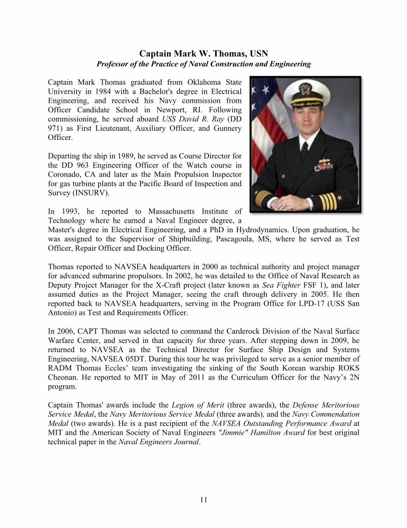
Captain Mark W. Thomas, USN Professor of the Practice of Naval Construction and Engineering
Captain Mark Thomas graduated from Oklahoma State University in 1984 with a Bachelor's degree in Electrical Engineering, and received his Navy commission from Officer Candidate School in Newport, RI. Following commissioning, he served aboard USS David R. Ray (DD 971) as First Lieutenant, Auxiliary Officer, and Gunnery Officer.
Departing the ship in 1989, he served as Course Director for the DD 963 Engineering Officer of the Watch course in Coronado, CA and later as the Main Propulsion Inspector for gas turbine plants at the Pacific Board of Inspection and Survey (INSURV).
In 1993, he reported to Massachusetts Institute of Technology where he earned a Naval Engineer degree, a Master's degree in Electrical Engineering, and a PhD in Hydrodynamics. Upon graduation, he was assigned to the Supervisor of Shipbuilding, Pascagoula, MS, where he served as Test Officer, Repair Officer and Docking Officer.
Thomas reported to NAVSEA headquarters in 2000 as technical authority and project manager for advanced submarine propulsors. In 2002, he was detailed to the Office of Naval Research as Deputy Project Manager for the X-Craft project (later known as Sea Fighter FSF 1), and later assumed duties as the Project Manager, seeing the craft through delivery in 2005. He then reported back to NAVSEA headquarters, serving in the Program Office for LPD-17 (USS San Antonio) as Test and Requirements Officer.
In 2006, CAPT Thomas was selected to command the Carderock Division of the Naval Surface Warfare Center, and served in that capacity for three years. After stepping down in 2009, he returned to NAVSEA as the Technical Director for Surface Ship Design and Systems Engineering, NAVSEA 05DT. During this tour he was privileged to serve as a senior member of RADM Thomas Eccles’ team investigating the sinking of the South Korean warship ROKS Cheonan. He reported to MIT in May of 2011 as the Curriculum Officer for the Navy’s 2N program.
Captain Thomas' awards include the Legion of Merit (three awards), the Defense Meritorious Service Medal, the Navy Meritorious Service Medal (three awards), and the Navy Commendation Medal (two awards). He is a past recipient of the NAVSEA Outstanding Performance Award at MIT and the American Society of Naval Engineers "Jimmie" Hamilton Award for best original technical paper in the Naval Engineers Journal.
12
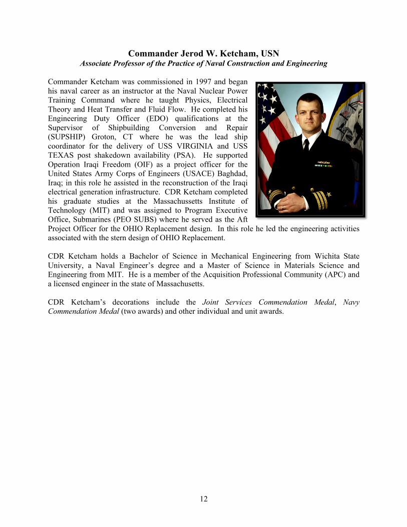
Commander Jerod W. Ketcham, USN Associate Professor of the Practice of Naval Construction and Engineering
Commander Ketcham was commissioned in 1997 and began his naval career as an instructor at the Naval Nuclear Power Training Command where he taught Physics, Electrical Theory and Heat Transfer and Fluid Flow. He completed his Engineering Duty Officer (EDO) qualifications at the Supervisor of Shipbuilding Conversion and Repair (SUPSHIP) Groton, CT where he was the lead ship coordinator for the delivery of USS VIRGINIA and USS TEXAS post shakedown availability (PSA). He supported Operation Iraqi Freedom (OIF) as a project officer for the United States Army Corps of Engineers (USACE) Baghdad, Iraq; in this role he assisted in the reconstruction of the Iraqi electrical generation infrastructure. CDR Ketcham completed his graduate studies at the Massachussetts Institute of Technology (MIT) and was assigned to Program Executive Office, Submarines (PEO SUBS) where he served as the Aft Project Officer for the OHIO Replacement design. In this role he led the engineering activities associated with the stern design of OHIO Replacement. CDR Ketcham holds a Bachelor of Science in Mechanical Engineering from Wichita State University, a Naval Engineer’s degree and a Master of Science in Materials Science and Engineering from MIT. He is a member of the Acquisition Professional Community (APC) and a licensed engineer in the state of Massachusetts. CDR Ketcham’s decorations include the Joint Services Commendation Medal, Navy Commendation Medal (two awards) and other individual and unit awards.
13
2014 2N Student Projects LCS Heavy Lift Tender Conversion ............................................................................................. 14
LT Jeff White, USN; LT Matt Williams, USN; LT Ryan Zachar, USN
Fuel-Efficient Destroyer, DDG(X) ............................................................................................... 16 LT Aaron Dobson, USN; LCDR Douglas Jonart, USN; LT Adam Jones, USN
T-AKE Humanitarian Assistance/ Disaster Relief (HA/DR) Conversion .................................... 18 LT Kerry Bosché, USN; LT Ian Campbell, USN; LT Ungtae Lee, USN; LT Vanea Pharr, USN
Special Operations Vessel (SOV) ................................................................................................. 20 LT Leon Faison, USN; LT Kyle Miller, USN; LT Kyle Woerner, USN
Whidbey Island Class LSD to SEAL Support Ship Conversion .................................................. 22 LT Brandy Dixon, USN; LT Kathleen McCoy, USN; LT Matt Strother, USN
Anti-Piracy Combatant ................................................................................................................. 24 LT Damian Oslebo, USN, LT Mark Ewachiw, USN, LTJG Vasileios Georgiadis, HN
14
LCS Heavy Lift Tender Conversion
LT Jeff White, USN; LT Matt Williams, USN; LT Ryan Zachar, USN
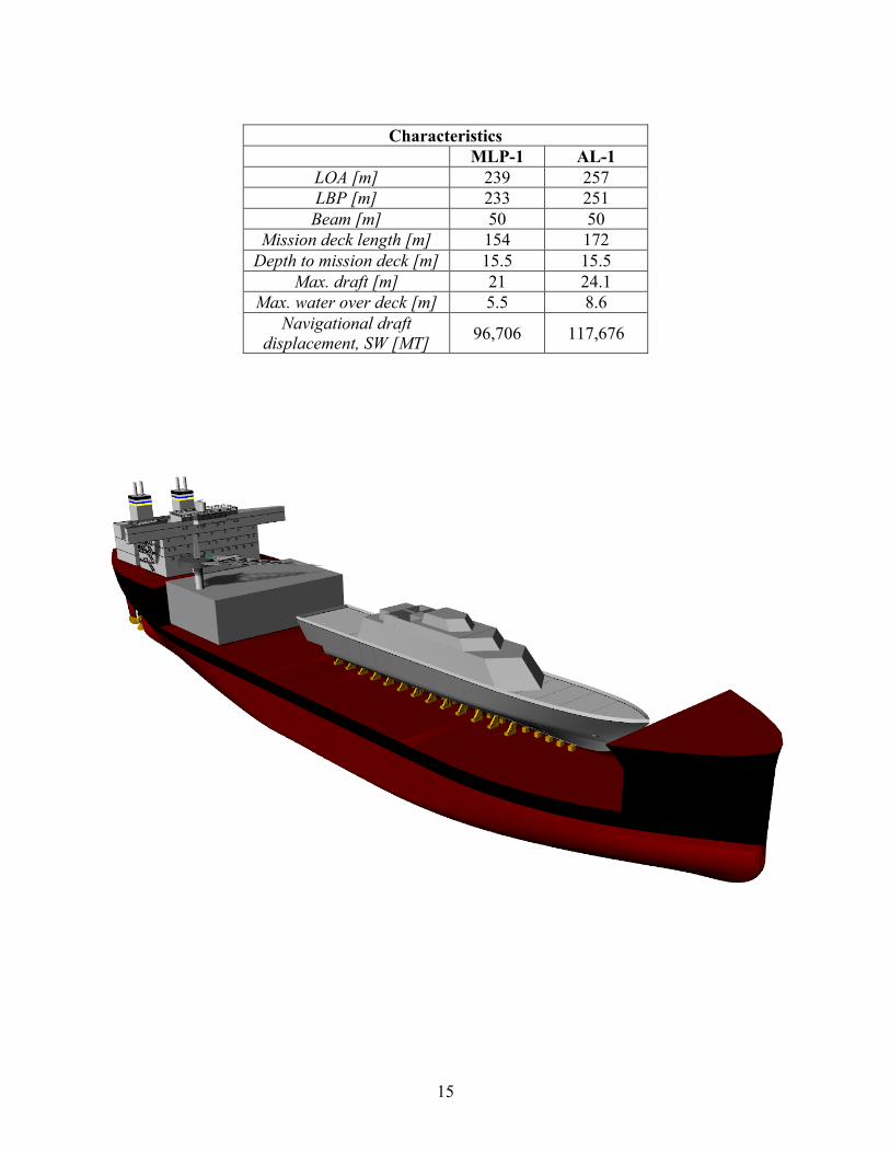
This study evaluated the design of the first ship of the Mobile Landing Platform-class, the USNS Montford Point (MLP-1), for conversion to service the anticipated large fleet of Littoral Combat Ships (LCS) in forward deployed locations. The new LCS Heavy Lift Tender (AL-1) was a modified repeat of the MLP-1 design. The AL-1 provides a floating drydock capable of lifting the Freedom or Independence-class LCS as well as a barge to serve as an Intermediate Maintenance Facility (IMF) for up to four ships at a time. The study included three major components: determining the size and weight of the maintenance barge, a heavy lift analysis of the AL-1 with the LCS and barge on deck, and an analysis of the strength, seakeeping, and cost of the AL-1. The MLP-1 is a maritime pre-positioning ship designed to provide logistics movement from sea to shore. It uses a semi-submersible mission deck to support three Landing Craft Air Cushion (LCAC) vessel lanes. In order to accommodate the new mission of heavy lift and repair, the ship needed to ballast down to a lower draft and have a longer mission deck. To meet these requirements an 18 meter section was added to the mid body. The new section contains six large ballast tanks which, along with approximately 10,000 MT of fixed ballast, allows the AL-1 to submerge to over 8.5 meters of water over deck. This is enough draft to dock both classes of LCS and provides a margin for some damaged conditions. The engineering analysis for the concept evaluation was conducted using Program of Ship Salvage Engineering (POSSE) 5. The AL-1 was evaluated against the strength and stability criteria for the MLP-1. A docking evolution with a fully loaded LCS-1 and maintenance barge was simulated using the heavy lift feature of POSSE 5 in order to validate the AL-1 design. A Freedom-class LCS with a draft of 4.3 meters and docking blocks set up in accordance NAVSEA drawings was run through the simulation to determine points of least stability. Also, the AL-1 was run through a linear seakeeping program to estimate the limiting sea state in the heavy lift condition. The maximum number of deck wetness events was used to determine the limiting case. The AL-1 provides the ability to drydock a LCS in a U.S. Navy facility anywhere in the world, something the Navy presently cannot do. This provides the ultimate flexibility to repair these ships in forward locations, without making a return transit to the United States. Additionally, the AL-1 provides the ability to conduct intermediate level maintenance in forward locations without any additional shore-based infrastructure, also a capability gap for the U.S. Navy. Using the 2N Auxiliary Cost Model, the total cost increase for the AL-1 over the MLP-1 is approximately $70 million in FY2011 dollars. The AL-1, built as a modified repeat with relatively simple design changes, would only cost 14 % more than building another MLP-1. A detailed design and cost analysis for the barge is an area for future study.
15
Characteristics
MLP-1 AL-1 LOA [m] 239 257 LBP [m] 233 251 Beam [m] 50 50
Mission deck length [m] 154 172 Depth to mission deck [m] 15.5 15.5
Max. draft [m] 21 24.1 Max. water over deck [m] 5.5 8.6
Navigational draft displacement, SW [MT] 96,706 117,676
16
Fuel-Efficient Destroyer, DDG(X)
LT Aaron Dobson, USN; LCDR Douglas Jonart, USN; LT Adam Jones, USN
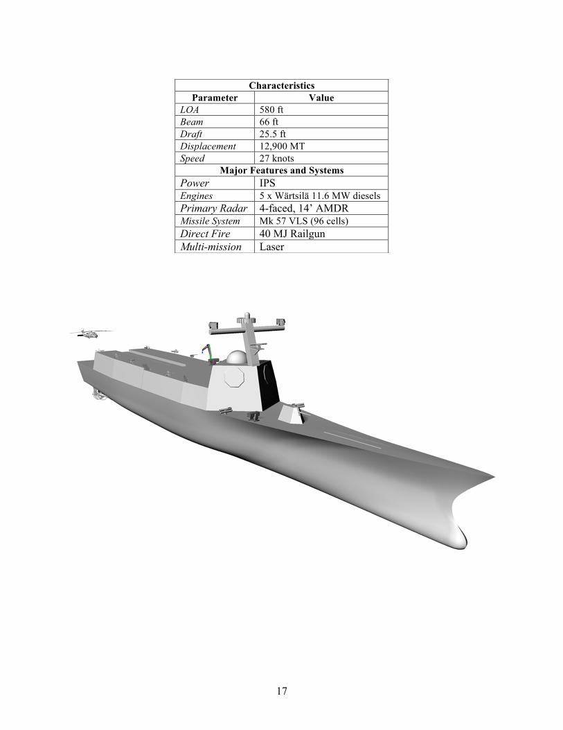
U.S. leaders at the highest levels, including the President and the Secretary of Defense, stated a need to reduce use and cost of fuels in the Navy. Desired equipment on and mission capabilities of destroyers both grew in the face of emerging threats and shrinking budgets. The existing DDG-51 class was reaching its limit to accept larger radars and mission systems, and it lacked the desired integrated power system (IPS) to enable these systems. The team designed a new destroyer, called DDG(X), to simultaneously meet these requirements. The size of DDG(X) was driven by the mission systems it needed to fill the numerous roles of a modern destroyer. A ballistic missile defense role demanded the Air and Missile Defense Radar (AMDR) and a 96-cell Mk 57 vertical launch missile system. All combat electronics required an upgrade, particularly the electronic warfare system. The standard deck gun was upgraded to a 40 megajoule railgun, and a laser was added. Both of these advanced systems filled numerous roles; testing on both systems indicated additional capabilities in the future. Support for special operations forces was improved in the new design, and unmanned aerial vehicles were added to its air complement. Deployable sonar systems completely replaced hull-mounted sensors, and the required maximum speed was set at 27 knots, lower than previous classes. Design of a hull to carry this equipment was completed using Design of Experiments (DOE). A baseline hull was developed from an existing hull design that had been intended for improved efficiency. This hull was scaled up to carry the DDG(X) equipment using a technique of scaling parameters in sets, while maintaining ratios proven through model testing to maintain the best hydrodynamic efficiency. Adaptations to the baseline hull were performed as iterations guided by the DOE until a minimum in resistance was achieved. Even though significantly larger than the DDG-51 hullform, this DDG(X) hullform showed a 14% reduction in drag. The speed-time profile from a recent destroyer field study, which detailed amount of time at each speed, was combined with anticipated use of electrical loads to develop a power-time profile representing the electrical demands on DDG(X) and its IPS. An optimization code was developed to evaluate the best possible use of a given set of engines to meet the demands of this power-time profile. The team updated the engine database and evaluated all practical options, selecting 5 Wärtsilä 11.6 MW 16V38 diesels to power DDG(X). These engines provided fuel savings of up to 28% over current destroyer engine selections. DDG(X) was shown to be an effective multi-mission destroyer that greatly reduced fuel consumption. Seakeeping was affected but acceptable to the team, and improvements could be made in future iterations of the design. Expanded use of diesels was recommended by the team for IPS ships.
17
Characteristics Parameter Value
LOA 580 ft Beam 66 ft Draft 25.5 ft Displacement 12,900 MT Speed 27 knots
Major Features and Systems Power IPS Engines 5 x Wärtsilä 11.6 MW diesels Primary Radar 4-faced, 14’ AMDR Missile System Mk 57 VLS (96 cells) Direct Fire 40 MJ Railgun Multi-mission Laser
18
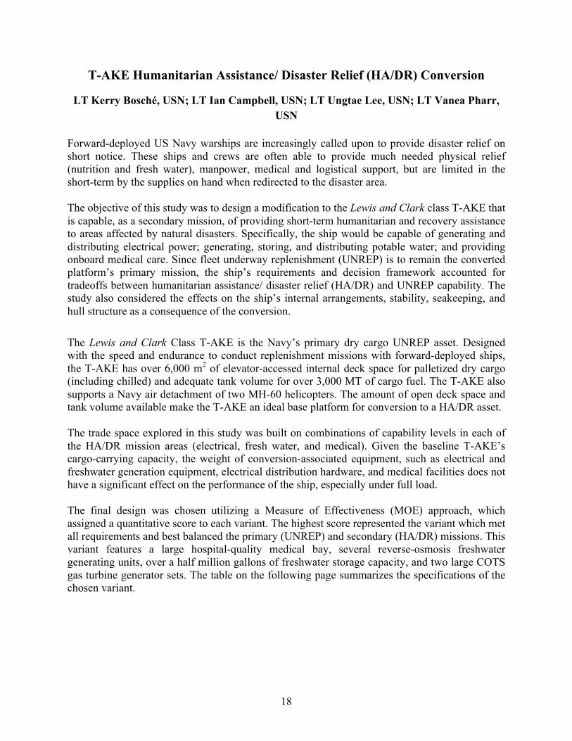
T-AKE Humanitarian Assistance/ Disaster Relief (HA/DR) Conversion
LT Kerry Bosché, USN; LT Ian Campbell, USN; LT Ungtae Lee, USN; LT Vanea Pharr, USN
Forward-deployed US Navy warships are increasingly called upon to provide disaster relief on short notice. These ships and crews are often able to provide much needed physical relief (nutrition and fresh water), manpower, medical and logistical support, but are limited in the short-term by the supplies on hand when redirected to the disaster area. The objective of this study was to design a modification to the Lewis and Clark class T-AKE that is capable, as a secondary mission, of providing short-term humanitarian and recovery assistance to areas affected by natural disasters. Specifically, the ship would be capable of generating and distributing electrical power; generating, storing, and distributing potable water; and providing onboard medical care. Since fleet underway replenishment (UNREP) is to remain the converted platform’s primary mission, the ship’s requirements and decision framework accounted for tradeoffs between humanitarian assistance/ disaster relief (HA/DR) and UNREP capability. The study also considered the effects on the ship’s internal arrangements, stability, seakeeping, and hull structure as a consequence of the conversion. The Lewis and Clark Class T-AKE is the Navy’s primary dry cargo UNREP asset. Designed with the speed and endurance to conduct replenishment missions with forward-deployed ships, the T-AKE has over 6,000 m2 of elevator-accessed internal deck space for palletized dry cargo (including chilled) and adequate tank volume for over 3,000 MT of cargo fuel. The T-AKE also supports a Navy air detachment of two MH-60 helicopters. The amount of open deck space and tank volume available make the T-AKE an ideal base platform for conversion to a HA/DR asset. The trade space explored in this study was built on combinations of capability levels in each of the HA/DR mission areas (electrical, fresh water, and medical). Given the baseline T-AKE’s cargo-carrying capacity, the weight of conversion-associated equipment, such as electrical and freshwater generation equipment, electrical distribution hardware, and medical facilities does not have a significant effect on the performance of the ship, especially under full load. The final design was chosen utilizing a Measure of Effectiveness (MOE) approach, which assigned a quantitative score to each variant. The highest score represented the variant which met all requirements and best balanced the primary (UNREP) and secondary (HA/DR) missions. This variant features a large hospital-quality medical bay, several reverse-osmosis freshwater generating units, over a half million gallons of freshwater storage capacity, and two large COTS gas turbine generator sets. The table on the following page summarizes the specifications of the chosen variant.
19
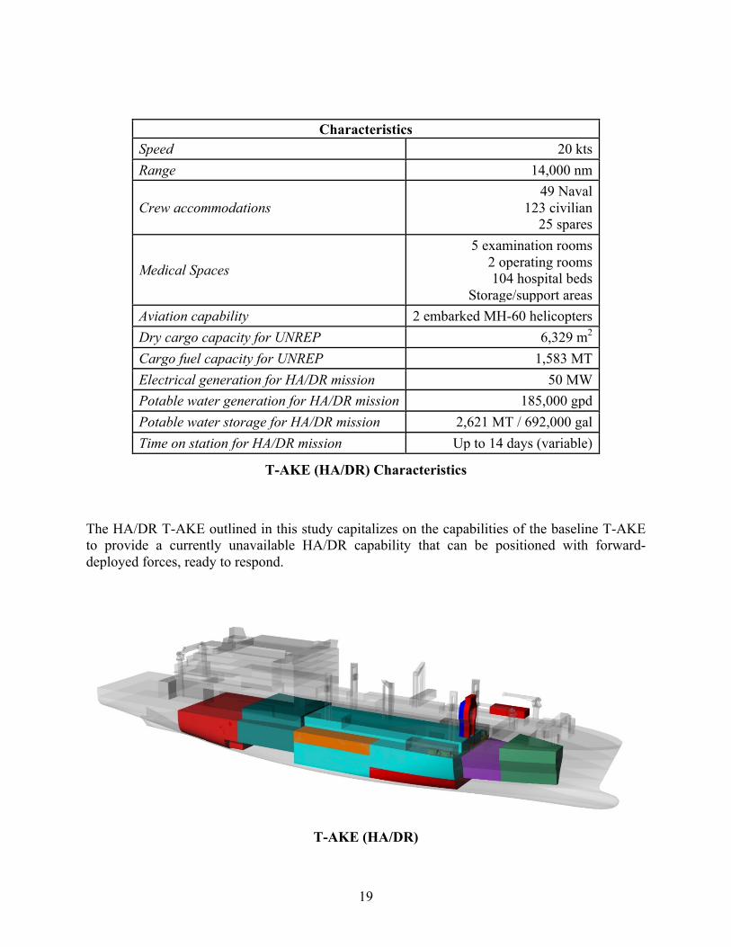
Characteristics Speed 20 kts Range 14,000 nm
Crew accommodations 49 Naval
123 civilian 25 spares
Medical Spaces
5 examination rooms 2 operating rooms 104 hospital beds
Storage/support areas Aviation capability 2 embarked MH-60 helicopters Dry cargo capacity for UNREP 6,329 m2 Cargo fuel capacity for UNREP 1,583 MT Electrical generation for HA/DR mission 50 MW Potable water generation for HA/DR mission 185,000 gpd Potable water storage for HA/DR mission 2,621 MT / 692,000 gal Time on station for HA/DR mission Up to 14 days (variable)
T-AKE (HA/DR) Characteristics
The HA/DR T-AKE outlined in this study capitalizes on the capabilities of the baseline T-AKE to provide a currently unavailable HA/DR capability that can be positioned with forward-deployed forces, ready to respond.
T-AKE (HA/DR)
20
Special Operations Vessel (SOV)
LT Leon Faison, USN; LT Kyle Miller, USN; LT Kyle Woerner, USN
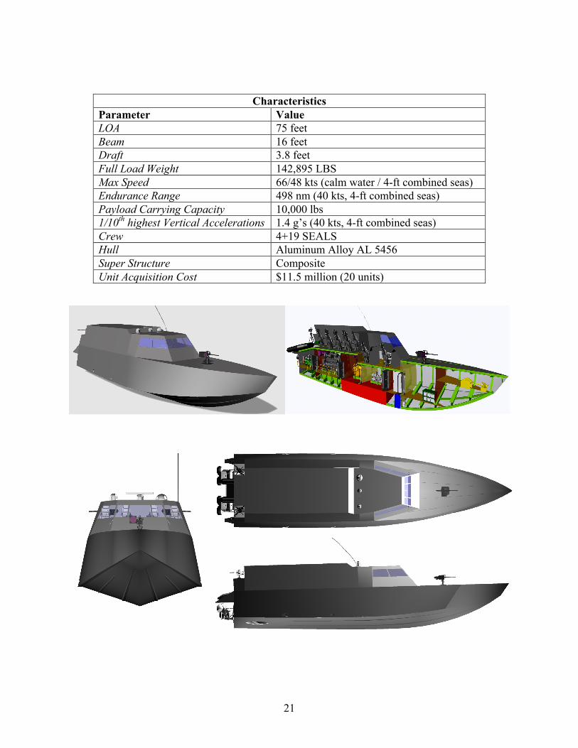
The National Defense Authorization Act of 2012 identifies a capability gap for future Special Operations Forces (SOF) missions. The Act cites the aging MK V Special Operations Craft and the delayed inception of the Combatant Craft Medium (CCM) as a critical shortfall in the ability to perform missions ranging from maritime interdiction to infiltration/extraction of personnel. In order to fill this mission capability gap, the Special Operations Vessel (SOV) is proposed. The SOV final concept design consists of a planing monohull craft with two water jet propulsors each driven by a single 16-cylinder diesel engine. The craft can deliver a payload of 10,000 pounds while achieving a sustained speed of 48 knots in 4-foot combined seas and an endurance range of 498 nautical miles at 40 knots. The SOV payload area has room to seat 19 SEALs plus two Rigid Hull Inflatable Boats (RHIB). The shock mitigating seats for the four special warfare combatant craft crewmen (SWCC) and the SEAL team are chosen for the required high speed transits. The hull and its features are designed to minimize vertical accelerations and is predicted to achieve an average of less than 1.5 g on its highest 1/10th vertical acceleration at its endurance speed and sea state. The hull is designed for aluminum construction with structural framing and reinforcement. Four watertight bulkheads are used to achieve single compartment flooding capability. Anchor stowage is forward of the collision bulkhead. Between the engine room and collision bulkhead are spaces for the electrical generator sets, communications equipment, and other mission critical gear. Hotel services are minimized at the customer’s direction based on the mission objectives and type of passengers carried aboard to include exclusion of dedicated berthing and messing areas from the general arrangements. The superstructure is designed for composite fabrication. Both space and function are major design considerations of the superstructure. Administrative transportation in a C-17 cargo plane requires fitting the appropriate payload and navigation equipment, including topside communication antennae. A limiting factor in the design is allowing removal of the superstructure for administrative transportation while still ensuring sufficient performance. The superstructure is also designed with fore and aft components to allow for modularity in both transportability as well as mission function. Missions requiring only the pilot house to be covered could see the removal of the aft superstructure. Missions requiring full coverage of the payload bay could be fit with both the fore and aft superstructures. Underway operations require the forward superstructure to be in place.
21
Characteristics Parameter Value LOA 75 feet Beam 16 feet Draft 3.8 feet Full Load Weight 142,895 LBS Max Speed 66/48 kts (calm water / 4-ft combined seas) Endurance Range 498 nm (40 kts, 4-ft combined seas) Payload Carrying Capacity 10,000 lbs 1/10th highest Vertical Accelerations 1.4 g’s (40 kts, 4-ft combined seas) Crew 4+19 SEALS Hull Aluminum Alloy AL 5456 Super Structure Composite Unit Acquisition Cost $11.5 million (20 units)
22
Whidbey Island Class LSD to SEAL Support Ship Conversion
LT Brandy Dixon, USN; LT Kathleen McCoy, USN; LT Matt Strother, USN
“Our recommendations seek to protect capabilities uniquely suited to the most likely missions of the future, most notably special operations forces used for counterterrorism and crisis response. Accordingly, our special operations forces will grow to 69,700 personnel from roughly 66,000 today.” - Secretary of Defense Chuck Hagel, February 24, 2014
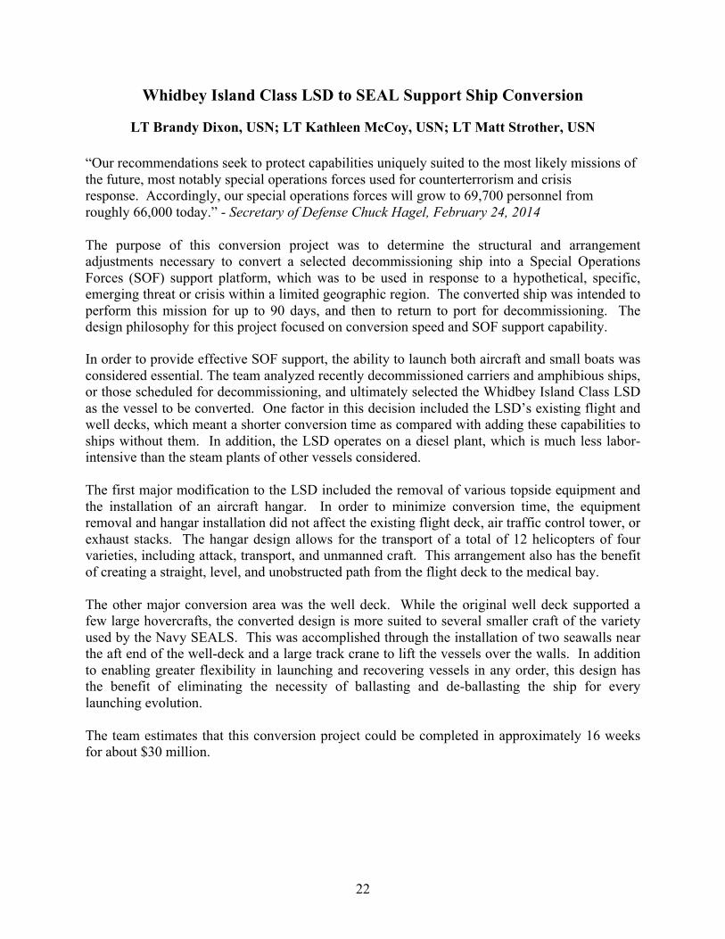
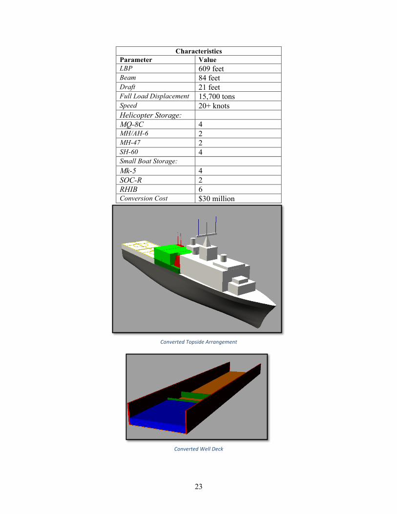
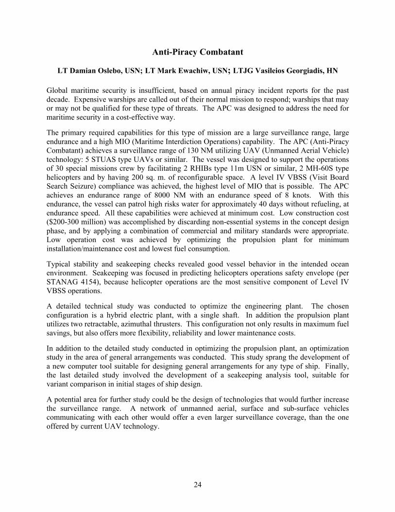
The purpose of this conversion project was to determine the structural and arrangement adjustments necessary to convert a selected decommissioning ship into a Special Operations Forces (SOF) support platform, which was to be used in response to a hypothetical, specific, emerging threat or crisis within a limited geographic region. The converted ship was intended to perform this mission for up to 90 days, and then to return to port for decommissioning. The design philosophy for this project focused on conversion speed and SOF support capability. In order to provide effective SOF support, the ability to launch both aircraft and small boats was considered essential. The team analyzed recently decommissioned carriers and amphibious ships, or those scheduled for decommissioning, and ultimately selected the Whidbey Island Class LSD as the vessel to be converted. One factor in this decision included the LSD’s existing flight and well decks, which meant a shorter conversion time as compared with adding these capabilities to ships without them. In addition, the LSD operates on a diesel plant, which is much less labor-intensive than the steam plants of other vessels considered. The first major modification to the LSD included the removal of various topside equipment and the installation of an aircraft hangar. In order to minimize conversion time, the equipment removal and hangar installation did not affect the existing flight deck, air traffic control tower, or exhaust stacks. The hangar design allows for the transport of a total of 12 helicopters of four varieties, including attack, transport, and unmanned craft. This arrangement also has the benefit of creating a straight, level, and unobstructed path from the flight deck to the medical bay. The other major conversion area was the well deck. While the original well deck supported a few large hovercrafts, the converted design is more suited to several smaller craft of the variety used by the Navy SEALS. This was accomplished through the installation of two seawalls near the aft end of the well-deck and a large track crane to lift the vessels over the walls. In addition to enabling greater flexibility in launching and recovering vessels in any order, this design has the benefit of eliminating the necessity of ballasting and de-ballasting the ship for every launching evolution. The team estimates that this conversion project could be completed in approximately 16 weeks for about $30 million.
23
Characteristics Parameter Value LBP 609 feet Beam 84 feet Draft 21 feet Full Load Displacement 15,700 tons Speed 20+ knots Helicopter Storage: MQ-8C 4 MH/AH-6 2 MH-47 2 SH-60 4 Small Boat Storage: Mk-5 4 SOC-R 2 RHIB 6 Conversion Cost $30 million
Converted Topside Arrangement
Converted Well Deck
24
Anti-Piracy Combatant
LT Damian Oslebo, USN; LT Mark Ewachiw, USN; LTJG Vasileios Georgiadis, HN
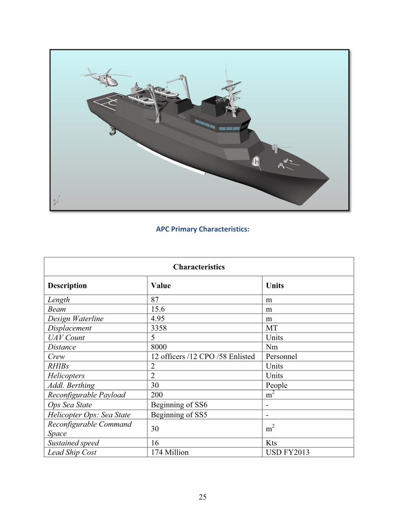
Global maritime security is insufficient, based on annual piracy incident reports for the past decade. Expensive warships are called out of their normal mission to respond; warships that may or may not be qualified for these type of threats. The APC was designed to address the need for maritime security in a cost-effective way.
The primary required capabilities for this type of mission are a large surveillance range, large endurance and a high MIO (Maritime Interdiction Operations) capability. The APC (Anti-Piracy Combatant) achieves a surveillance range of 130 NM utilizing UAV (Unmanned Aerial Vehicle) technology: 5 STUAS type UAVs or similar. The vessel was designed to support the operations of 30 special missions crew by facilitating 2 RHIBs type 11m USN or similar, 2 MH-60S type helicopters and by having 200 sq. m. of reconfigurable space. A level IV VBSS (Visit Board Search Seizure) compliance was achieved, the highest level of MIO that is possible. The APC achieves an endurance range of 8000 NM with an endurance speed of 8 knots. With this endurance, the vessel can patrol high risks water for approximately 40 days without refueling, at endurance speed. All these capabilities were achieved at minimum cost. Low construction cost ($200-300 million) was accomplished by discarding non-essential systems in the concept design phase, and by applying a combination of commercial and military standards were appropriate. Low operation cost was achieved by optimizing the propulsion plant for minimum installation/maintenance cost and lowest fuel consumption.
Typical stability and seakeeping checks revealed good vessel behavior in the intended ocean environment. Seakeeping was focused in predicting helicopters operations safety envelope (per STANAG 4154), because helicopter operations are the most sensitive component of Level IV VBSS operations.
A detailed technical study was conducted to optimize the engineering plant. The chosen configuration is a hybrid electric plant, with a single shaft. In addition the propulsion plant utilizes two retractable, azimuthal thrusters. This configuration not only results in maximum fuel savings, but also offers more flexibility, reliability and lower maintenance costs.
In addition to the detailed study conducted in optimizing the propulsion plant, an optimization study in the area of general arrangements was conducted. This study sprang the development of a new computer tool suitable for designing general arrangements for any type of ship. Finally, the last detailed study involved the development of a seakeeping analysis tool, suitable for variant comparison in initial stages of ship design.
A potential area for further study could be the design of technologies that would further increase the surveillance range. A network of unmanned aerial, surface and sub-surface vehicles communicating with each other would offer a even larger surveillance coverage, than the one offered by current UAV technology.
25
APC Primary Characteristics:
Characteristics
Description Value Units
Length 87 m Beam 15.6 m Design Waterline 4.95 m Displacement 3358 MT UAV Count 5 Units Distance 8000 Nm Crew 12 officers /12 CPO /58 Enlisted Personnel RHIBs 2 Units Helicopters 2 Units Addl. Berthing 30 People Reconfigurable Payload 200 m2
Ops Sea State Beginning of SS6 - Helicopter Ops: Sea State Beginning of SS5 - Reconfigurable Command Space 30 m2
Sustained speed 16 Kts Lead Ship Cost 174 Million USD FY2013
26
2014 2N Student Theses
Submarine Propulsion Shaft Life: Probabilistic Prediction and Extension through Prevention of Water Ingress ................................................................................................................................ 27
LCDR Douglas Jonart, USN
Design of a High Speed Planing Hull with a Cambered Step and Surface Piercing Hydrofoils .. 28 LT Leon A. Faison, USN
Design and Assessment of a Super High Speed, Hybrid Hydrofoil/SWATH Crew Boat ............ 29 LTJG Vasileios Georgiadis, HN
COLREGs - Compliant Autonomous Collision Avoidance Using Multi-Objective Optimization with Interval Programming ........................................................................................................... 30
LT Kyle Woerner, USN
Mechanical Characterization of Lithium-Ion Battery Micro Components for the Development of Homogenized and Multilayer Material Models ............................................................................ 31
LT Kyle Miller, USN
Design of an Autonomous Underwater Vehicle (AUV) Charging System for Underway, Underwater Recharging ................................................................................................................ 32
LT Mark A. Ewachiw, USN
Cost Prediction via Quantitative Analysis of Complexity in U.S. Navy Shipbuilding ................ 33 LT Aaron T. Dobson, USN
Design Space Exploration and Optimization Using Modern Ship Design Tools ......................... 34 LT Adam Thomas Jones, USN
Design of Tool for the Optimization of Deck Area Assignments with Integration into Existing Naval Ship Design Programs ........................................................................................................ 35
LT Damian Oslebo, USN
Improving the Parametric Method of Cost Estimating Relationships of Naval Ships ................. 36 LT Ungtae Lee, USN
Gasoline Engine Emission Characterization and Gasoline Particulate Filter Advanced Aging System ........................................................................................................................................... 37
LTJG James Jorgensen, USCG
27
Submarine Propulsion Shaft Life: Probabilistic Prediction and Extension through Prevention of Water Ingress
LCDR Douglas Jonart, USN
Prof. Alex Slocum Prof. Ronald Ballinger
Thesis Supervisor Thesis Supervisor Current submarine propulsion shafts provide the necessary reliability when they are inspected and refurbished at least every 72 months. In several decades of service, no shaft failures have been experienced, and inspection results support continued performance. The next class of submarines requires equivalent reliability when inspected and refurbished at least every 144 months. Experience and improved design have eliminated many threats to the life of a submarine shaft, leaving corrosion fatigue as the current concern with the greatest risk. Inspections of existing shafts show a high percentage with signs of wetting, leaving designers with less-than-acceptable confidence to approve this longer service life. Many paths might achieve the necessary shaft life; this paper focuses on quantifying the necessary level of water ingress prevention. Methods to prevent water ingress include seals, O-rings, and protective coatings. No direct information is available on which systems currently fail, nor when, allowing water to contact the shaft steel; only summary data of inspection results and numbers of defects have been reliably recorded.
This thesis uses probabilistic models from literature for pitting and cracking of wetted shafts, along with Monte Carlo simulations, to predict results of shafts inspections. Each possible water ingress distribution is analyzed by simulating shafts under 72 months of exposure to the water ingress, pitting, and cracking models. A water ingress distribution that predicts inspection results closest to actual inspection results is identified. Some information about water ingress can be inferred from this distribution. Next, using the same literature models, a water ingress distribution that predicts acceptable performance at 144 months is identified. The two water ingress distributions are compared, though it is identified that poor metrics exists for comparing distributions in this way. Despite this difficulty, it is shown that the time a shaft is in service prior to becoming wetted must increase substantially. As one example, it is estimated that in the current design around one-third of shafts have developed water ingress by the 1000 day point, while for acceptable performance in the next class, only about three percent can be wetted in this time. This thesis recommends that inspection procedures are updated to provide more robust information for future analyses, which would better identify the appropriate distributions and greatly reduce uncertainty.
Naval Engineer
28
Design of a High Speed Planing Hull with a Cambered Step and Surface Piercing Hydrofoils
LT Leon A. Faison, USN
Prof. Chryssostomos Chryssostomidis Dr. Stefano Brizzolara
Thesis Supervisor Thesis Advisor Design of a high speed planing hull is analyzed by implementing a cambered step and stern, surface piercing hydrofoils, commonly known as a Dynaplane hull. This configuration combines the drag reduction benefits of a stepped hull with a fully ventilated afterbody by using a stern stabilizer. The largest obstacle with this design is maintaining trim control and stability at high speeds. There has been limited research on the Dynaplane design since Eugene Clement first conducted tow tank tests in the David Taylor Model Basin in the 1960s. Modern experimental methods such as computational fluid dynamics (CFD) allow the designer to run multiple simulations at once while testing a variety of parametric variables. The analysis in the design will combine theoretical, empirical, and computational methods to ultimately determine the hydrodynamic characteristics for such a design. The design approach begins with using a reference hull from a small systematic series of resistance tests at the DTMB, named Model 5631. This modeled hull is based on the U.S. Coast Guard 47’ Motor Lifeboat which is a hard chine, deep V planing hull. Clement’s Dynaplane design process was followed with exception of the stern stabilizer recommendation. Instead, a surface piercing, super cavitating hydrofoil designed by Dr. Stefano Brizzolara was used. Their designs further improve upon the powering requirements and effectively increasing the lift to drag ratio compared to a traditional transverse step. A commercially available CFD software package called Star-CCM+ is used for the computational portion. The test procedures require to first validate the computational model using results from the Model 5631 tow tank tests, then proceed with comparing empirical predictions with those results gathered from the computational model. Lastly, the computational results give hydrodynamic characteristics for the Dynaplane hull and provide predictions for dynamic instability. Three series of CFD tests were conducted; developing wake geometry predictions for a swept back, stepped hull, and then varying the trim angle and longitudinal center of gravity for the Dynaplane configuration. These tests were run at a volumetric Froude number of 5 in a calm sea state. Results from the analysis determine threshold values for trim angle and LCG location to avoid dynamic instabilities such as a bow drop occurrence or porpoising. Also, the results extend the range of application of Clement’s Dynaplane design to hulls with 20 degree deadrise. This thesis gives naval architects design guidance for such a hullform and demonstrates the potential of CFD as a tool for analyzing these parametric variables. Naval Engineer Master of Science in Mechanical Engineering
29
Design and Assessment of a Super High Speed, Hybrid Hydrofoil/SWATH Crew Boat
LTJG Vasileios Georgiadis, HN
Prof. Chryssostomos Chryssostomidis Dr. Stefano Brizzolara
Thesis Supervisor Thesis Advisor MIT Innovative Ship Design Lab has worked on the hydrodynamic design of a family of hybrid SWATH/Hydrofoil unmanned surface vehicles, published in the 11th International Conference on Fast Sea Transportation (September 2011). This research is the first effort to expand this family of vessels and include manned vehicles. The focus of this thesis was the preliminary design and feasibility assessment of Wavecutter, a high speed vessel designed to provide rapid and flexible crew transportation to and from offshore oil rigs. Wavecutter is based on its unmanned predecessor, the Ultrafast Hybrid HYGE (Hydrofoil Ground Effect)-SWATH (120 knots with 500 NM endurance range). Wavecutter’s main characteristics are shown below:
• 85 knots with 480 NM endurance range at full speed • Payload capacity of 24 passengers and 15 MT cargo • Required crew of 4 • Operational sea state 4
Wavecutter operates in two modes: displacement (0-17 knots) and foil borne (17-85 knots). In displacement mode, buoyancy is provided by two SWATH hulls and propulsion power by two diesel engines/generator sets through motor driven propellers mounted in the aft of the hulls. In foil borne mode, about 90% of the lift is provided by four surface piercing, super-cavitating hydrofoils that are mounted in the fore and aft parts of the SWATH hulls. The remaining lift is provided by the wing shaped main deck, that is connected to the SWATH hulls via struts. Propulsion thrust in foil borne mode is generated by two turbo fans, located right and left in the aft part of the wing deck. The manned compartments are located in the middle part of the wing deck, inside a tube shaped capsule, which provides structural support and enhances safety. In the design phase, emphasis was placed in the manned compartments, the creation of which was inspired by airplane internal arrangements. Hydrofoil sizing also required attention, and it was found that front foils need to be larger than the aft, to counteract the large moment produced by the turbo fans. In the feasibility analysis phase, emphasis was placed in static and dynamic stability. Static stability analysis confirmed the inherent stability of the surface piercing, negative dihedral angle configuration in foil borne mode. Dynamic behavior analysis results were also reassuring, but future work is recommended using Computational Fluid Dynamic method to model the dynamic behavior of the vessel more accurately. Naval Engineer Master of Science in Mechanical Engineering
30
COLREGs - Compliant Autonomous Collision Avoidance Using Multi-Objective Optimization with Interval Programming
LT Kyle Woerner, USN
Prof. John J. Leonard Dr. Michael Benjamin
Thesis Supervisor Thesis Advisor High contact density environments are becoming ubiquitous in autonomous marine vehicle (AMV) operations. Safely managing these environments while still accomplishing their mission greatly taxes platforms. A legitimate concern exists that AMV collisions could become more frequent as contact density increases. In situations where AMVs are not necessarily performing a collaborative mission but are instead only using shared physical space such as multiple vehicles running on the same river, a high demand exists for safe and efficient operation to minimize mission track deviations while preserving the safety and integrity of mission platforms. With no existing protocol for collision avoidance of AMVs, much effort to date has focused on individual ad hoc collision avoidance approaches that are self-serving, lack the uniformity of fleet-distributed protocols, and disregard the overall fleet efficiency when scaled to being in a contact-dense environment. This research shows that by applying interval programming and a collision avoidance protocol such as the International REGULATIONS for Prevention of Collisions at Sea (COLREGs) to a fleet of AMVs operating in the same geographic area, the fleet achieves identical mission efficiency concurrent with significant reductions in the number of collisions observed. Within this research, a basic collision avoidance protocol was analyzed against an AMV-COLREGs protocol while parameters key to collision avoidance were studied using regression testing and analysis of both real-world and simulated statistical data. Further, a testing metric was proposed for declaring AMVs as "COLREGs-compliant" for at-sea operations. Naval Engineer Master of Science in Mechanical Engineering
31
Mechanical Characterization of Lithium-Ion Battery Micro Components for the Development of Homogenized and Multilayer Material Models
LT Kyle Miller, USN
Prof. Tomasz Wierzbicki Thesis Supervisor
Recent developments in lithium-ion battery technology are enabling the rapid expansion of the electric car market. Most of the current research and developments deal with controlling the environment surrounding the battery, such as voltage discharge and cooling controls, or large metal casings. The research of the Impact and Crashworthiness Laboratory (ICL) at MIT focuses on understanding the battery’s mechanical properties so that individual battery cells and battery packs can be characterized during crash events. The objective of this research is to better understand the battery component (electrode and separator) properties under different loading conditions. Over 200 tests were conducted on battery components. These tests include uniaxial stress, biaxial punch, multilayer, single layer, short-circuit testing, wet vs dry specimen testing, strain rate testing, and more. Additionally, a scanning electron microscope was used to view the battery components and better understand the aforementioned test results. Of note, it was discovered that many of the electrodes in the Li-ion batteries are damaged during the battery manufacturing process. Also, the two methods of manufacturing battery separator were analyzed and their resulting mechanical properties were characterized. These results will be used to further refine and validate a high-level, robust, and accurate computational tool to predict strength, energy absorption, and the onset of electric short circuit of batteries under real-world crash loading situations. The cell deformation models will then be applied to the battery stack and beyond, thereby enabling rationalization of greater optimization of the battery pack/vehicle combination with respect to tolerance of battery crush intrusion behavior. Besides improving crash performance, the finite element models contribute substantially to the reduction of the cost of prototyping and shorten the development cycle of new electric vehicles. Naval Engineer Master of Science in Mechanical Engineering
32
Design of an Autonomous Underwater Vehicle (AUV) Charging System for Underway, Underwater Recharging
LT Mark A. Ewachiw, USN
Prof. Chryssostomos Chryssostomidis Prof. James L. Kirtley
Thesis Supervisor Thesis Advisor Modern robotics have enabled the rapid proliferation of Autonomous Underwater Vehicles (AUVs) throughout the marine environment with AUVs performing an ever-increasing array of complex missions. Maritime tasks that once required a fleet of ships, months to complete, and countless bodies are now being performed by AUVs with little to no logistical support elements. Despite the many AUV technology advances that have been made, power remains a limiting factor. The current method for deploying an AUV requires charging it above water, shipping it to a mission site, and then deploying it overboard with the use of cranes. The AUV is then recovered once the mission is complete or – more likely – when its power source is depleted. The deployment and recovery phases are time-intensive, limited by weather conditions and sea state, and often hazardous to both crew and AUV. While deployment and recovery will remain critical, high-risk evolutions, there exists a need to find a safer and faster recharging method that does not require recovery of the vehicle. This thesis solves a fraction of the underwater AUV power transfer and rapid charging challenge through the development of the power electronics required to reliably charge a single battery pack. Power is supplied inductively to a receiver coil in the AUV. This power is then transferred to a down converter with a current-sensing feedback controller to provide a regulated current under the varying load voltage of the battery pack. The system is capable of providing up to 500W of instantaneous power to a single pack. It is electrically isolated from the power source through the use of an input transformer and is compact enough to be integrated into an AUV for future testing. Power is always a challenge. This system, when fielded, will allow an AUV to approach a surface vessel while submerged, recharge its power cell within approximately 15 minutes, and continue its mission(s) without the need for retrieval and redeployment. Naval Engineer SM Electrical Engineering and Computer Science
33
Cost Prediction via Quantitative Analysis of Complexity in U.S. Navy Shipbuilding
LT Aaron T. Dobson, USN
Prof. Olivier de Weck Dr. Eric Rebentisch Prof. Mark Thomas
Thesis Supervisor Thesis Advisor Thesis Advisor As the sophistication and technology of ships increases, U.S. Navy shipbuilding must be an effective and cost efficient acquirer of technology-dense ships while meeting significant cost and schedule constraints in a fluctuating demand environment. A drive to provide world-class technology to the U.S. Navy’s warfighters necessitates increasingly complex ships, which further augments the non-trivial problem of providing cost effective, on-schedule ships for the American taxpayer. The primary objective of this study was to quantify, assess, and analyze cost predictive complexity-oriented benchmarks in the pre-construction phase of the U.S. Navy’s ship acquisition process via an adaptation of research produced by Prof. de Weck and Sinha in 2012. Complexity was quantified via three overarching factors:
• Component complexity – an aggregation of eight factors including performance levels, re-use, risk, and performance tolerance levels. Each factor was normalized, weighted, and summed by subsystem.
• Interface complexity – an assessment of the interfaces in each subsystem. • Subsystem topological complexity.
Each subsystem’s quantified net complexity was mapped to its procurement cost as published by U.S. Congressional reports. This study used commercially available software such as Mathwork’s MATLAB software to analyze the numerical cost data and assess the fidelity of the predictive benchmarks to the datasets. The end result was that a consideration of complexity via the methods and algorithms established in this study supported an exponential cost versus complexity relationship to refine the current cost estimation methods and software currently in use in U.S. Navy shipbuilding. Naval Engineer Master of Science in Engineering and Management
34
Design Space Exploration and Optimization Using Modern Ship Design Tools
LT Adam Thomas Jones, USN
Prof. Jerod Ketcham Mr. Pat Hale
Thesis Supervisor Thesis Reader Modern Naval Architects use a variety of design tools to explore feasible options for clean sheet ship designs. Under the Naval Sea Systems Command (NAVSEA), the Naval Surface Warfare Center, Carderock Division (NSWCCD) has created computer tools for ship design and analysis purposes. This paper presents an overview of some of these tools, specifically the Advanced Surface Ship Evaluation Tool (ASSET) version 6.3 and the Integrated Hull Design Environment (IHDE). The goal of the paper is to provide a detailed explanation of a ship design using these advanced tools and to present methods for optimizing the performance of the hullform and for optimizing the engines selected for the ship. The detailed ship design will explore the design space given a set of specific requirements for a cruiser-type naval vessel. The hullform optimization technique entails the reduction of a ship’s residual resistance by using both ASSET and IHDE in a Design of Experiments (DoE) approach to reaching an optimum solution. The paper will provide a detailed example resulting in a 12% reduction in total ship drag by implementing this technique on a previously designed hullform. The engine selection optimization technique involves a MATLAB code that calculates the engine configuration at all required ship powers that minimizes fuel consumption. For a given speed-time or power-time profile, the code will evaluate hundreds of combinations of engines and provide the optimum engine combination for reducing the total fuel consumption. This optimization has the potential to reduce fuel consumption of current naval warships by upwards of 30%. Naval Engineer Master of Science in Engineering and Management
35
Design of Tool for the Optimization of Deck Area Assignments with Integration into Existing Naval Ship Design Programs
LT Damian Oslebo, USN
Prof. Chryssostomos Chryssostomidis Dr. Julie Chalfant Prof. Fredo Durand
Thesis Supervisor Thesis Advisor Thesis Advisor Many tasks in the early stages of ship design are manual and repetitive processes. One such task is in the realm of deck area arrangements. The allocation and assignment of areas in early stage ship design involves tracking the difference of total ship area envelope and all required areas to be placed for habitability, mission support, and propulsion capability among many. The problem becomes more complex with the addition of constraints involving required separation zones between other areas, affinities for certain areas or deck levels, and compartment subdivision. The Leading Edge Architecture for Prototyping Systems (LEAPS) database structure output from the Advanced Ship and Submarine Evaluation Tool (ASSET) provides a ship envelope and a list of areas requiring assignment. However, with over a hundred different area categories to place in a subdivided ship hull of a large number of compartments each with their own preferences and constraints, this problem is categorized as Non-deterministic Polynomial-time hard(NP). Essentially meaning that finding the optimal solution in the design space is not realistically feasible as the problem scales upwards in size. Fortunately, this type of problem, known as Bin Packing, is well understood in academic research. Meta-heuristic methods of obtaining near optimal solutions in a finite timeframe exist that are reasonable enough for use. This thesis presents the framework for a ship design tool that pairs two of these meta-heuristic methods with naval ship architecture and LEAPS based projects. The framework is divided into three major steps: a ship volume balance, a ship area balance, and an area layout of the ship footprint. The output of the tool is the general arrangements drawings in a universal CAD format that would be the starting point into more detailed arrangements. Naval Engineer Master of Science in Electrical Engineering and Computer Science
36
Improving the Parametric Method of Cost Estimating Relationships of Naval Ships
LT Ungtae Lee, USN
Dr. Eric Rebentisch Prof. Mark Thomas Thesis Supervisor Thesis Reader
In light of recent military budget cuts, there has been a recent focus on determining methods to reduce the cost of Navy ships. A 2006 RAND National Defense Research Institute study showed many sources of cost escalation for Navy ships. Among them included characteristic complexity of modern Naval ship, which contributed to half of customer driven factors. This paper focuses on improving the current parametric cost estimating method used as referenced in NAVSEA’s Cost Estimating Handbook. Currently, weight is used as the most common variable for determining cost in the parametric method because it’s a consistent physical property and most readily available. Optimizing ship design based on weight may increase complexity because it tends to decrease the size of a ship. This paper will introduce power density and outfit density as additional variables to the parametric cost estimating equation and will show how this can improve the early stage cost estimating relationships of Navy ships. Master of Science in Naval Architecture and Marine Engineering Master of Science in Engineering and Management
37
Gasoline Engine Emission Characterization and Gasoline Particulate Filter Advanced Aging System
LTJG James Jorgensen, USCG
Dr. Victor Wong Thesis Supervisor
Worldwide focus on the reduction of emissions from internal combustion engines has become a major driving factor in the development of new engine technologies. One such technology is direct fuel injection for downsized gasoline engines in light duty road vehicles; while direct injection offers significant fuel economy and CO/NOX emission advantages, it also emits elevated levels of particulate matter (PM) in the form of soot, on par with small diesel engines. Near-future emissions regulations impose strict limits on PM emissions from gasoline engines, and one strategy for meeting these limits is the use of gasoline particulate filters (GPF). These filters are manufactured from a porous ceramic substrate called cordierite, which offers excellent capture efficiency for both incombustible ash – derived from consumption of lubricating oils – and PM in the form of soot. Soot is periodically purged from the filter through regeneration, an elevation of temperature of the filter which combusts all remaining soot in the filter. As the filters age, incombustible ash is accumulated, increasing backpressure and affecting system performance. This project developed a novel accelerated aging system, consisting of a gasoline fueled combustion chamber with lubricant oil injection, thereby simulating the major sources of PM emissions from a combustion engine. This system allows rapid accumulation of incombustible ash in the GPF, to simulate a full useful life of 150,000 miles in a matter of a few weeks. The system was validated by comparison to previous results and engine out emissions obtained from a co-located 1.6L Ford direct injection engine. Multiple GPF were loaded to various ash levels, pressure drop recorded, then ash distribution and morphology were characterized using advanced imaging techniques, particularly Transmission Electron Microscopy (TEM) and 3-Dimensional Computed Tomography (CT) Scanning. Master of Science in Naval Architecture and Marine Engineering

38
Notes:

39
Notes:

40
Notes: