cross-layer codesign for resilient hardware
TRANSCRIPT

© Xinfei Guo | Confidential
Cross-layer Codesign for Resilient Hardware
Xinfei Guo, Ph.D.U of Virginia & NVIDIA Corporation
Westborough, MA
Jan 29th, 2021
Boston (and Beyond) Area Architecture Workshop (BARC)

© Xinfei Guo | Confidential BARC 2021
Outlinen Why?n What?n How?n Now what?
2

© Xinfei Guo | Confidential BARC 2021
Starting from Transistors – Aging/Wearoutn Time-dependent device degradations
q Transistors (P/NMOS)q Metal layers (Interconnect, PDN)
Vth
BTI
Ids
BTI
R
EM
td
BTIEM
BTI
Interconnect
PDN
PDN
BTI
EM
EM
PMOS
NMOS
BTI → Bias Temperature InstabilityEM → Electromigration
PDN → Power Delivery NetworkVth → Threshold VoltageIds → CurrentR → Resistancetd → Propagation Delay
3
© Xinfei Guo | Confidential BARC 2021
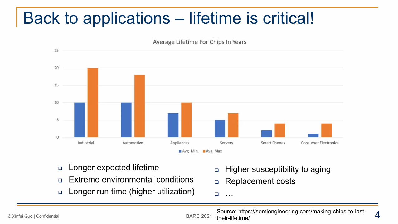
Back to applications – lifetime is critical!
Source: https://semiengineering.com/making-chips-to-last-their-lifetime/
q Longer expected lifetimeq Extreme environmental conditionsq Longer run time (higher utilization)
q Higher susceptibility to agingq Replacement costsq …
4

© Xinfei Guo | Confidential BARC 2021
Aging – Industry Attentions
Source: [semiengineering.com] 5

© Xinfei Guo | Confidential BARC 2021
n Reliability threat!q Permanent errors
q Shorten lifetime
q Worsen metrics such as performance, power and area
n Getting worse with technology scaling!
q Increased power density → Heat
q Increased effective electrical field
→ More stress
q More components → Require
lower single failure rate
q Advanced nodes → New stress
and issues: e.g. self-heating
Why do we care about aging now?
Figure: [N. Cheung et al., UC Berkeley]
Wire broke due to EM
Source: [S.M. Ramey, et al. (Intel), 2018]
FinFETs More Aging
6

© Xinfei Guo | Confidential BARC 2021
A cross-layer effectn Device level
q Threshold voltage Vth increase (BTI)q Resistance increase (EM)
n Circuit levelq Performance degradationq Timing failuresq Leakage power
n Architecture levelq Failuresq Errors
n System levelq MTTF
7

© Xinfei Guo | Confidential BARC 2021
Traditional solutions
Adding Margins
• Over-estimation• Under-estimation• Uncertain operation
conditions• e.g. 10% for a 3-year
lifetime constraint
Adapting(Sensing + Actuation)
• The worst case is getting worse
• Aging is unchecked• Tracking power (over
10 sensors per partition)
Passive Recovery(More idle time)
• Very slow • Unpredictable• Permanent part will
keep accumulating
Single-layer solution is not adequate to deal with aging any more as it is becoming a bottleneck!
8

© Xinfei Guo | Confidential BARC 2021
Introducing Accelerated Self-Healingn Fact - Aging is partially recoverable under passive recovery, but it is very
slow.n Key Idea: Reverse the directions of aging and enable active Recovery
Sleep/Rejuvenatio
n
Active
Healing
/
Recovery
Active
/Aging
? ?
9

© Xinfei Guo | Confidential BARC 2021
Accelerated Self-HealingKey Idea: Recover by reversing the directions of Aging
Vsg = 0, room
Passive Recovery
Vsg = 0, high
Accelerated RecoveryActivate the recovery
Vsg = negative room temperature
Active Recovery:
Vsg = negativehigh temperature
Accelerated & Active 1 2 3 4Recovery
temperature temperature
I = 0, room
Passive Recovery
I = 0, high
Accelerated RecoveryActivate the recovery
I = negative room temperature
Active Recovery:
I = negativehigh temperature
Accelerated & Active 1 2 3 4Recovery
temperature temperature
BTI Accelerated Self-Healing
EM Accelerated Self-Healing
Baseline
Baseline
10

© Xinfei Guo | Confidential BARC 2021
Experiments for demonstration
Interface Board ChipData Sampling
16-b
fref clk
in
Cout16
En En
75 LUTs
Circuit Under Test (CUT)rst
(a) (b)
Thermal Chamber
Counter
BTI Test Setup
Resistance Recording
Thermal Chamber
Constant Current Supply Device (Wire) under test
Technology 180nmMaterial Copper
Thickness 0.8umLength 2.673mmWidth 1.57um
Resistance (@rt) 35.76W
Probe Pads
Metal Wire
EM Test Setup
40nm FPGA
On-chip Metal Wires
11

© Xinfei Guo | Confidential BARC 2021
Measurement results summary
n Recovery from aging can be made active and be accelerated, even the irreversible component can be fullyeliminated or avoided through various techniques such as higher temperatures, negative voltages, active vs. sleep ratio …
n What does this mean for chip designers and architects?A: Cross-layer Accelerated Self-Healing
12X. Guo, etc. DAC ‘14, ASP-DAC ‘16, DSN ‘17

© Xinfei Guo | Confidential BARC 2021
Implication – Metric Improvementsq >60x reduction of necessary margin for all casesq The average performance is close to the fresh during the whole lifetimeq Both metrics don’t scale with the increase of the lifetime constraint
~ 2X
~ 1X
Reduction of Necessary Design Margin Average Performance Improvement
13X. Guo, etc. ASP-DAC ‘16

© Xinfei Guo | Confidential BARC 2021
Cross-layer Accelerated Self-Healing
-∆VActive Recovery
EN
CircuitWearout Sensors
ArchitectureDark Silicon
ProgramCounters
+1
SystemVirtualSensorsLoad Balancer
Heating Elements
AcceleratedRecoveryEN
Negative Voltage Generator
Proactive Scheduler
RedundantResources
14X. Guo, etc. VLSI, Integration ‘17

© Xinfei Guo | Confidential BARC 2021
Circuit Components for Self-HealingBTI Accelerated
Self-Healing Circuits
On-Chip Negative Voltage Generator
Power Gating enables Recovery
EM Accelerated Self-Healing Circuits
EM and BTI Recovery Assist
Circuitry
On-Chip Heater
Wearout Sensing Circuits
BTI Sensing
RO-based for N/PBTI Sensing
Metastable Element Based Sensor
EM Sensing
-300.6mV
638ns
-300.6mV
4.36mV
4.33mV
Ripple: 1.45%
Clock frequency = 66.7MHz
Vdd
clk1
clk2
clk1C1 C2
Non-overlapping clock generator
clk1
clk2
clk
charging charge redistribution
Vout
Sleep
VoltageNegative
Logic Blocks
VddVdd_high
Sleep
Boosted Vdd
GeneratorNegative Voltage
Vdd
SleepEn
Power Gating Block
D Q
RetentionRegisters
Always ON
To other power gating blocks
Sleep_buf
Vddv
Accelerated Recovery
Reconfigurable Heating Element
outputReconfigurable
ROs
MU
X
L
L/2
L/4
Out
track poll1
poll2
poll3
track
discharg discharg
ref
10%
5%
2%path0track poll1
poll2
poll3
discharg discharg
ref
10%
path1
path2
path3
10%
10%
track
track
poll1
poll2
poll3
(a) (b)
outa outb
M10
M9
M8
M7
M6
M5
C4 Bump
M4M3M2
P4 P3 LoadP1P2VDD
VDD Via
VDD_PAD
EM
EM
EM
Global PDN
Connect to VSS Grid
Connect to VSS Grid
VDD Grid(EM hazards)
BTI
15X. Guo, etc. Springer ‘20

© Xinfei Guo | Confidential BARC 2021
Costsn Area ↓ Power ↓ Extra Heat ↓
q Optimal ways of distributing circuit IPs in a large systemq Avoid unwanted heatq Trigger only when necessary
Design Name Leakage Power Dynamic Power Area Performance
Neg. Voltage Generator 68.85nW 64.47uW 4300um2 >66.7MHz
On-Chip Heater 16.8nW 75uW 16um2 -
Multi-modeRecovery Circuit - - 58.24um2 Wakeup time ~170ns
Are there any other opportunities beyond circuit level?
16

© Xinfei Guo | Confidential BARC 2021
Architectural Simulation Framework for Architecture Level
Exploration – “OldSpot”
17
Example Output of the tool -> Aging HotSpot!
A CPU Layout
Mor
e A
ging
Crit
ical
A. Roelke, X. Guo, etc. ICCD ‘18
https://github.com/hplp/oldspot

© Xinfei Guo | Confidential BARC 2021
Unit-level Accelerated Self-Healing
n Goal
q Less area and power overhead
n Solution
q Placing self-healing IPs only for aging-critical units
Heat Map(From “HotSpot”)
Wearout Map(From “OldSpot*”)
rob
heat
ers
Neg
. Vo
ltage
18X. Guo, etc. Springer ‘20

© Xinfei Guo | Confidential BARC 2021
Utilize Intrinsic Heat
Sha
red
Mem
ory
t1 t2
Sha
red
Mem
ory
n Goalq Avoid power overhead for generating extra heat
n Solutionq Take advantage of dark silicon or core redundancyq Utilize intrinsic sleep behaviors
19X. Guo, etc. Springer ‘20

© Xinfei Guo | Confidential BARC 2021
Scheduling for Recovery
23.2min
57.8min
344.3min
104.5min
Full recovery time after 12-hour constant stress under normal condition
n Goalq Recover effectively only when necessary
Perfo
rman
ce (a
.u.)
a% - Preset Threshold
Wearout Sensors Trigger PointAccelerated and Active RecoveryNormal Operation
Reactive Recovery
Proactive Recovery
Preset Schedule
Time0
Accumulated WearoutClock
Frequency
AC Stress
Passive Recovery
Proactive Recovery Application-dependent Scheduling
20

© Xinfei Guo | Confidential BARC 2021
Putting it All Together: CLASH - Cross-layer Accelerated Self-Healing System
• Accelerated Self-Healing Assist Circuitry• On-chip negative voltage generator• Power gating recovery enabler• On-chip Heater
• Aging and Recovery Sensing Circuitry• BTI Sensor
• RO Based• Metastable element based
• EM Sensor
• Unit-level Accelerated Self-Healing• Take advantage of dark silicon or core redundancy• Utilize intrinsic sleep behaviors
• Scheduling for Recovery• Proactive Recovery
• Application dependent scheduling
21

© Xinfei Guo | Confidential BARC 2021
CLASH System – Hardware view
EM/BTI Assist Circuitry
EM ActiveRecovery
NormalOperation
BTI ActiveRecovery Heat Flow
Wearout Sensors &RecoveryCircuitry
RecoveryCircuits
22

© Xinfei Guo | Confidential BARC 2021
What is the key benefit of doing cross-layer codesign here?
Before…• Margin (e.g. 10 – 20 %)• Track and Adaptation (Track
during the entire lifetime)• Passive recovery (<20%
recovery percentage)
Accelerated Self-Healing• Margin (0.21%)• Only track the reversible part (~ 8X
tracking power reduction)• As high as 100% recovery rate• Cross-layer implementation
minimizes the cost • Recovery-driven design method
*All numbers are based on the model prediction which is calibrated by measurements.
Constraints (Close to data center or IoT application cases)• 10 year lifetime constraint• Under DC stress• Operating at room temperature• Nominal Vdd
23

© Xinfei Guo | Confidential BARC 2021
Sleep for rejuvenating and healing neurons?
24https://www.scientificamerican.com/article/lack-of-sleep-could-be-a-
problem-for-ais/
© Xinfei Guo | Confidential BARC 2021
Key takeawaysn Device level behaviors will have a lasting impact to all
upper layersn Cross-layer codesign is an essential way of enlarging the
search spacen Challenges co-exist with opportunities
q Infrastructuresq Transparencyq Design cycleq …
26

© Xinfei Guo | Confidential BARC 2021
References1. X. Guo, W. Burleson, M. Stan, “Modeling and Experimental Demonstration of
Accelerated Self-Healing Techniques,” ACM/IEEE Design Automation Conference (DAC), 2014.
2. X. Guo, M. Stan, “Work hard, sleep well - Avoid irreversible IC wearout with proactive rejuvenation,” ACM/IEEE Asia and South Pacific Design Automation Conference (ASP-DAC), 2016.
3. X. Guo, M. Stan, “Deep Healing: Ease the BTI and EM Wearout Crisis by Activating Recovery,” International Conference on Dependable Systems and Networks (DSN), 2017.
4. X. Guo, M. Stan, "Implications of Accelerated Self-Healing as a Key Design Knob for Cross-Layer Resilience", INTEGRATION, the VLSI journal (VLSI), vol. 56, pp. 167-180, 2017.
5. A. Roelke, X. Guo, M. Stan, “OldSpot: A Pre-RTL Model for Aging and Lifetime Optimization,” ICCD, 2018.
6. X. Guo, V. Verma, P. Guerrero, M. Stan, “When things get older - Exploring Circuit Aging in IoT Applications," International Symposium on Quality Electronic Design (ISQED), 2018.
7. X. Guo, M. Stan, “Circadian Rhythms for Future Resilient Electronic Systems -- Accelerated Active Self-Healing for Integrated Circuits”, Springer, 2020.
27
