corrosion in oil gas
TRANSCRIPT

7/28/2019 Corrosion in Oil Gas
http://slidepdf.com/reader/full/corrosion-in-oil-gas 1/108
CORROSION AND
ITS PROTECTION
IN OIL & GAS PRODUCTION

7/28/2019 Corrosion in Oil Gas
http://slidepdf.com/reader/full/corrosion-in-oil-gas 2/108
CORROSION IN OIL FILED :
INTERNAL AND EXTERNAL THREATS
7/28/2019 Corrosion in Oil Gas
http://slidepdf.com/reader/full/corrosion-in-oil-gas 3/108
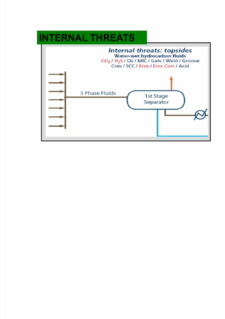
INTERNAL THREATS

7/28/2019 Corrosion in Oil Gas
http://slidepdf.com/reader/full/corrosion-in-oil-gas 4/108
WELL TREATMENT
INFLUENCED
WATER CARRY OVER
UNDERDOSING
DEMULSIFIER
INJECTION PUMP with
LOWCAPACITY
UNDERDOSING
CORROSION
INHIBITOR
WATER SETTLE OUT
CORROSION CAUSES
7/28/2019 Corrosion in Oil Gas
http://slidepdf.com/reader/full/corrosion-in-oil-gas 5/108
5
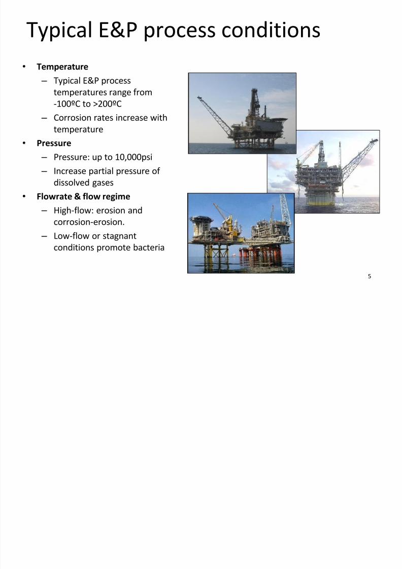
Typical E&P process conditions
•Temperature – Typical E&P process
temperatures range from
-100ºC to >200ºC
– Corrosion rates increase with
temperature
• Pressure
– Pressure: up to 10,000psi
– Increase partial pressure of
dissolved gases
• Flowrate & flow regime
– High-flow: erosion and
corrosion-erosion.
– Low-flow or stagnant
conditions promote bacteria

7/28/2019 Corrosion in Oil Gas
http://slidepdf.com/reader/full/corrosion-in-oil-gas 6/108
6
Internal corrosion
Hydrocarbon phase
• Not normally corrosive at
temperatures experienced in
production systems
• Corrosivity depends onextent and distribution of the
aqueous and hydrocarbon
phases.
Aqueous phase
• Responsible for corrosion
• Corrosion exacerbated by acid
gases & organic acids
• CO2, H2S and O2 are the most
aggressive species
• Chlorides increase corrosion
• Generally,
–
‘no water, no corrosion’

7/28/2019 Corrosion in Oil Gas
http://slidepdf.com/reader/full/corrosion-in-oil-gas 7/108
7
Internal (process-side) damage
mechanisms
• H2S
• CO2
• Solids & velocity effects
• Chlorides – pitting, stress corrosion cracking
• Oxygen (crevice / under deposit / differential aeration)
• Galvanic corrosion
• Preferential weld corrosion (PWC)
• Microbially induced corrosion (MIC)
• Liquid metal embrittlement (LME)
• Chemicals
7/28/2019 Corrosion in Oil Gas
http://slidepdf.com/reader/full/corrosion-in-oil-gas 8/108
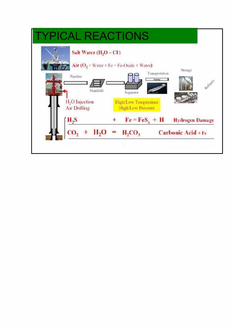
TYPICAL REACTIONS

7/28/2019 Corrosion in Oil Gas
http://slidepdf.com/reader/full/corrosion-in-oil-gas 9/108
9
There is no species more corrosive on a concentration basis than
oxygen!
Corroded seawater injectio
Dissolved gas - effect on corrosion
0
5
10
15
20
25
0 1 2 3 4 5 6 7 8 C o r r o s i o n R
a t e
o f
C a r b o n S
t e e l
O2
CO2
H2S
Dissolved Gas Concentration in Water Phase, ppm
0 1 2 3 4 5 6 7 8
0 100 200 300 400 500 600 700 800
0 50 100 150 200 250 300 350 400
O2
H2S
CO2

7/28/2019 Corrosion in Oil Gas
http://slidepdf.com/reader/full/corrosion-in-oil-gas 10/108
10
H2S CORROSION
7/28/2019 Corrosion in Oil Gas
http://slidepdf.com/reader/full/corrosion-in-oil-gas 11/108
11
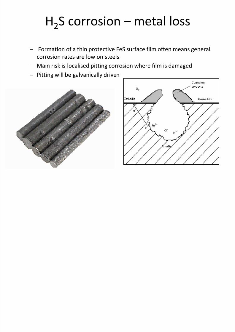
H2S corrosion – metal loss
– Formation of a thin protective FeS surface film often means general
corrosion rates are low on steels
– Main risk is localised pitting corrosion where film is damaged
– Pitting will be galvanically driven

7/28/2019 Corrosion in Oil Gas
http://slidepdf.com/reader/full/corrosion-in-oil-gas 12/108
12
Wet H2S corrosion
• H2S is soluble in water
– Produces a weak acid and lowers the pH
H2S H+ + SH-
– At low concentrations, H2S helps form protective FeS film
– Main risk is localised pitting corrosion which can be rapid
• H2S also poisons combination of atomic hydrogen into molecular
hydrogen
H+ + e- H
H + H H2
X
Atomic hydrogen -
dangerous to steels!!

7/28/2019 Corrosion in Oil Gas
http://slidepdf.com/reader/full/corrosion-in-oil-gas 13/108
13
Cracking in sour service
H H H
H
H
Higher Strength Steels YS > 500 MPa Low Strength Steels YS < 550 MPa
Applied Stress No Applied Stress
H 2
H 2
H 2
H + S 2-
Fe 2+
H
H
FeS Film
Metal Matrix

7/28/2019 Corrosion in Oil Gas
http://slidepdf.com/reader/full/corrosion-in-oil-gas 14/108
14
Sulphide stress cracking (SSC)
Key parameters:• pH and pH2S
– Domain diagrams for carbon steel
• Material hardness
– High strength steels and areas of
high hardness susceptible.• Temperature
– Maximum susceptibility at lowtemperatures for carbon steels (15-25°C), higher for CRAs (5-70°C).
•
Stress – Cracking promoted by high stress
levels e.g. residual welding
HAZ WELD HAZ
Hardness readings

7/28/2019 Corrosion in Oil Gas
http://slidepdf.com/reader/full/corrosion-in-oil-gas 15/108
15
Protection against SSC
• Avoid wetness
• Minimise hardness
– Guidance on limits inISO 15156
•Optimise microstructureand minimise residualstresses
Upgrade to CRAs
• Martensitic and duplex stainless
steels have limited resistance
• H2S limits for duplex and super-
duplex steels are complex
– Function of temperature, pH,
chlorides, pH2S
• Nickel-base alloys such as 625
and 825 have high resistance
• Testing: NACE TM0177
7/28/2019 Corrosion in Oil Gas
http://slidepdf.com/reader/full/corrosion-in-oil-gas 16/108
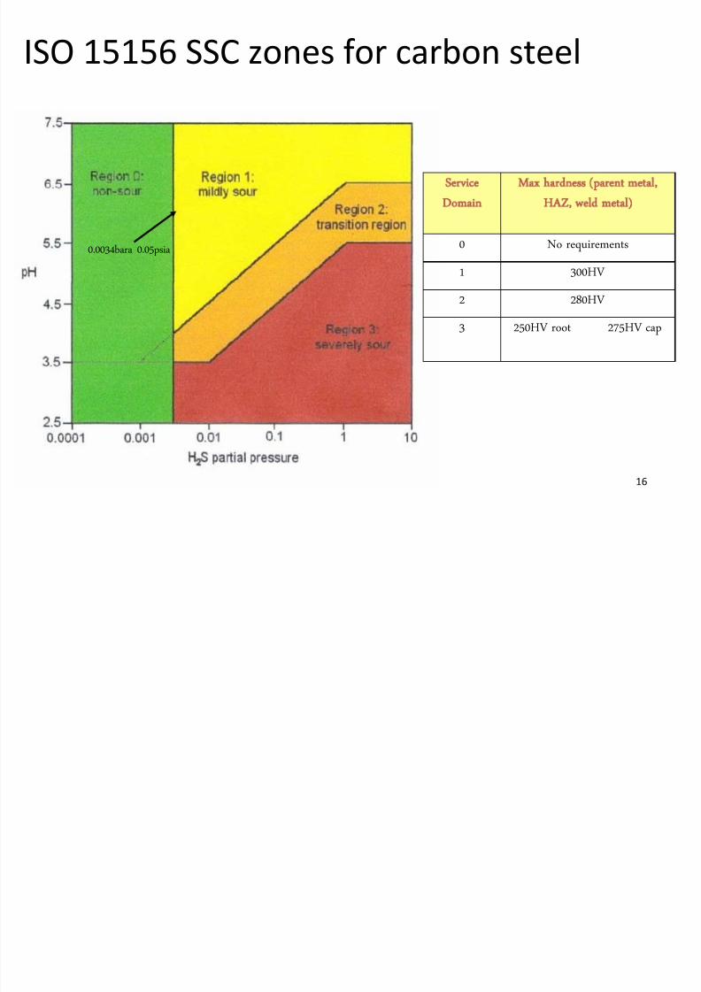
16
ISO 15156 SSC zones for carbon steel
0.0034bara 0.05psia
Service
Domain
Max hardness (parent metal,
HAZ, weld metal)
0 No requirements
1 300HV
2 280HV
3 250HV root 275HV cap

7/28/2019 Corrosion in Oil Gas
http://slidepdf.com/reader/full/corrosion-in-oil-gas 17/108
17
SSC limits for selected CRAs
Alloy pH2S limit (bara)
13% Cr martensitic 0.008
22% Cr duplex 0.10
25% Cr super-duplex 0.25
Alloy 825 No limit
Alloy 625 No limit
7/28/2019 Corrosion in Oil Gas
http://slidepdf.com/reader/full/corrosion-in-oil-gas 18/108
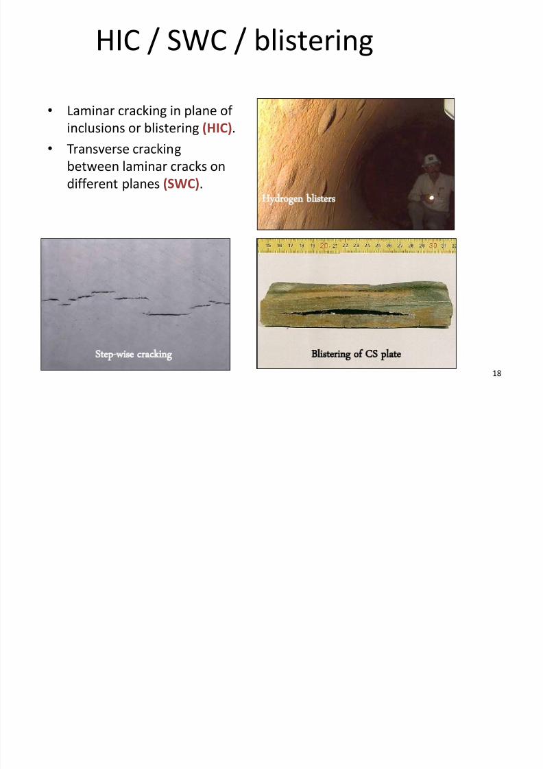
18
HIC / SWC / blistering
• Laminar cracking in plane of
inclusions or blistering (HIC).
• Transverse cracking
between laminar cracks on
different planes (SWC).
Step-wise cracking Blistering of CS plate
Hydrogen blisters

7/28/2019 Corrosion in Oil Gas
http://slidepdf.com/reader/full/corrosion-in-oil-gas 19/108
19
Avoiding HIC / SWC
• Avoid plate steels (rolled)
– otherwise qualify by HIC test
• Control impurities e.g. S, P
• Uniform microstructure• Use internal coatings
– isolate steel from process fluid
• Testing: NACE TM0284Banded
Uniform

7/28/2019 Corrosion in Oil Gas
http://slidepdf.com/reader/full/corrosion-in-oil-gas 20/108
20
ISO 15156 (NACE MR0175)• ISO 15156 combination of
– NACE MR0175 and NACE testing requirements TM0177 & TM0284
– European Federation of Corrosion Guidelines No.16 & 17
• Part 1: General principles for selecting crack-resistant materials
• Part 2: Cracking resistant carbon & low-alloy steels & cast iron
• Part 3: Cracking resistant corrosion resistant alloys (CRAs)• Covers all cracking mechanisms
• Goes beyond application of the 0.05 psia pH2S threshold for sour service
• It is the equipment user’s responsibility to select suitable materials
• HIC/SWC of flat rolled carbon steel products for environments containing even
trace amounts of H2S to be evaluated
• BP ETP: GP 06-20 Materials for Sour Service

7/28/2019 Corrosion in Oil Gas
http://slidepdf.com/reader/full/corrosion-in-oil-gas 21/108
21
Designing for H2S service
• Materials requirements
– Reference ISO 15156 and GP 06-20
– pH2S and pH
– Temperature
– Chlorides – Hardness limits
• Welding QA/QC (HIC)
– Maintain hardness limits
•
HIC testing for plate products

7/28/2019 Corrosion in Oil Gas
http://slidepdf.com/reader/full/corrosion-in-oil-gas 22/108
22
CO2 CORROSION

7/28/2019 Corrosion in Oil Gas
http://slidepdf.com/reader/full/corrosion-in-oil-gas 23/108
23
CO2 - containing environments
• CO2 always present in produced
fluids
– Corrosive to carbon steel
when water present
– Most CRAs have goodresistance to CO2 corrosion.
Mechanism
CO2 + H2O H2CO3
H2CO3 + e-HCO3- + H
2HH2
Fe Fe2+ + 2e-
Fe + H2O + CO2 FeCO3 + H2

7/28/2019 Corrosion in Oil Gas
http://slidepdf.com/reader/full/corrosion-in-oil-gas 24/108
24
Types of CO2 damage
Mesa corrosion
Localised weld corrosionlow-assisted-corrosion (CO2)
General & pitting corrosion

7/28/2019 Corrosion in Oil Gas
http://slidepdf.com/reader/full/corrosion-in-oil-gas 25/108
25
CO2 corrosion in a production
flowline
• 6” CS production flowline (Magnus, 1983)
• 25mm thick, 90bar, 30°C, 2%CO2
• Heavily pitted pipe wall and welds (not necessarily uniform
corrosion)
• Didn’t fail – removed due to crevice corrosion of hub sealing
faces

7/28/2019 Corrosion in Oil Gas
http://slidepdf.com/reader/full/corrosion-in-oil-gas 26/108
26
Factors in CO2 corrosion
• Main factors
– pCO2, temperature, velocity, pH
- CO2 prediction model
Temperature, (ºC) pCO2 (bar) Carbon steel corrosion rate
(mm/yr)
130 0.6 7
75 0.6 6
149 30 >50
For an ideal gas mixture, the partial pressure is the
pressure exerted by one component if it alone occupied
the volume. Total pressure is the sum of the partial
pressures of each gas component in the mixture

7/28/2019 Corrosion in Oil Gas
http://slidepdf.com/reader/full/corrosion-in-oil-gas 27/108
27
Effect of sand on CO2 corrosion
• Produced sand can affect inhibitor efficiency
– Inhibitor adsorption loss
• Sand (and other solid) deposits give increased risk of localised corrosion;
– Prevent access of corrosion inhibitor to the metal
– Provide locations for bacteria proliferation – Galvanic effects (area under deposit at more negative potential than
area immediately adjacent to deposit)
– Formation of concentration cells/gradients

7/28/2019 Corrosion in Oil Gas
http://slidepdf.com/reader/full/corrosion-in-oil-gas 28/108
28
Mitigation of CO2 corrosion
• Internal CO2 corrosion of carbon steel needs to be managed
– Usually mitigate by chemical inhibitors
– Simple geometries only (mainly pipelines)
• Assume inhibitor availability (90-95%)
– Inhibited corrosion rate of 0.1mm/year – Remaining time at full predicted corrosion rate
– Apply a corrosion allowance for the design life
– If calculated corrosion allowance >8mm use CRAs

7/28/2019 Corrosion in Oil Gas
http://slidepdf.com/reader/full/corrosion-in-oil-gas 29/108
29
CO2 corrosion inhibition
• Filming type
• Retention time
• Continuous injection
• Adsorption onto clean surfaces
Clean steel
7/28/2019 Corrosion in Oil Gas
http://slidepdf.com/reader/full/corrosion-in-oil-gas 30/108
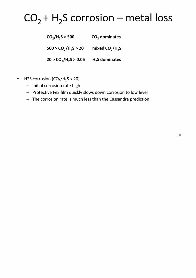
30
CO2 + H2S corrosion – metal loss
• H2S corrosion (CO2/H2S < 20)
– Initial corrosion rate high
– Protective FeS film quickly slows down corrosion to low level
–
The corrosion rate is much less than the Cassandra prediction
CO2/H2S > 500 CO2 dominates
500 > CO2/H2S > 20 mixed CO2/H2S
20 > CO2/H2S > 0.05 H2S dominates

7/28/2019 Corrosion in Oil Gas
http://slidepdf.com/reader/full/corrosion-in-oil-gas 31/108
H2S + CO2 materials selection guide
Carbon/low alloy steels
Duplex SS
Nickel-based alloys
Partial pressure H2S (bar)
P a r t i a l p r e s s u r e C O 2
( b a r )
13% Cr SS

7/28/2019 Corrosion in Oil Gas
http://slidepdf.com/reader/full/corrosion-in-oil-gas 32/108
32
EROSION & EROSION-CORROSION

7/28/2019 Corrosion in Oil Gas
http://slidepdf.com/reader/full/corrosion-in-oil-gas 33/108
33
Flow regimes
Liquid
Gas
Bubble (bubbly) flow
Stratified flow
Gas
Liquid
Annular flow
Churn flow
Gas iquid
Gas
Liquid
Plug flow
Wave (wavy) flow
Liquid Gas
Slug flow
Mist (spray) flow
• Various multi-phase flow regimes
possible;
− erosion characteristics
− distribution of phases
− carrier phase for solids
• Flow regimes with particles in the gas
show higher erosion rates than those
with particles in the liquid phase.

7/28/2019 Corrosion in Oil Gas
http://slidepdf.com/reader/full/corrosion-in-oil-gas 34/108
34
Erosion & erosion-corrosion
• Erosion
– Caused by high velocity impact
& cutting action of liquid and/or
solid particles
– Erosion failures can be rapid• Erosion-corrosion
– Occurs in environments that are
both erosive and corrosive.
– Erosion and corrosion can be
independent or synergistic. Erosion of tungsten carbide choke trim

7/28/2019 Corrosion in Oil Gas
http://slidepdf.com/reader/full/corrosion-in-oil-gas 35/108
35
Typical vulnerable areas for erosion
• Areas wherever flow is restricted ordisturbed
– T-pieces, bends, chokes, valves, weldbeads
• Areas exposed to excessive flow rates
• Sand washing – Washing infrequently allowing sand to
accumulate
– High pressure drop during washing of separators
• Sea water systems
– High flow areas in water injection /cooling systems
Trinidad
Algeria (duplex)

7/28/2019 Corrosion in Oil Gas
http://slidepdf.com/reader/full/corrosion-in-oil-gas 36/108
36
Erosion in piping
• Sand accumulation
– Build up of sand in a test separator
• Pressure drop
– Large pressure drop across sand
drain pipework during washing• Rapid failure
– Occurred within 2 minutes of
opening the drain
Erosion at bend

7/28/2019 Corrosion in Oil Gas
http://slidepdf.com/reader/full/corrosion-in-oil-gas 37/108
37
Erosion in a vessel
•
Sand allowed to accumulate in separator – Wash nozzles embedded in sand
• PCV not working properly
– High pressure / flowrate
– Nozzle not erosion-resistant
– Erosion of wash nozzle
– Spray changed to a jet causing erosion
of shell
• Local changes to operating procedures not
communicated
– Frequency of sand washing
– Risk not captured or assessed in RBI
Water spray
Water jet

7/28/2019 Corrosion in Oil Gas
http://slidepdf.com/reader/full/corrosion-in-oil-gas 38/108
38
Erosion of sandwash nozzle
Progressive nozzle damage

7/28/2019 Corrosion in Oil Gas
http://slidepdf.com/reader/full/corrosion-in-oil-gas 39/108
39
Erosion-corrosion
• Occurs in environments that can be erosive and corrosive.
• Erosion and corrosion can either be:
– independent of each other;
• wastage equals sum of individual wastage rates
– synergistic;
• wastage rate > sum of individual rates
• localised protective film breakdown at bends, elbows
areas of turbulence

7/28/2019 Corrosion in Oil Gas
http://slidepdf.com/reader/full/corrosion-in-oil-gas 40/108
40
Impingement
• Water speed or local turbulence damages or removes protective
film
• 90-10 Cu-Ni susceptible to internal erosion-corrosion (impingement)
at velocities >3.5ms-1
• Water-swept pits (horse-shoe shaped)

7/28/2019 Corrosion in Oil Gas
http://slidepdf.com/reader/full/corrosion-in-oil-gas 41/108
41
Cavitation
• Occurs at high fluid velocities
• Formation & collapse of vapour bubbles
in liquid flow on metal surface.
• No solids required
• Typical locations – Pump impellers (rapid change in pressure
which damages films)
– Stirrers, hydraulic propellers
• Use erosion resistant materials
– Stellite, tungsten carbide

7/28/2019 Corrosion in Oil Gas
http://slidepdf.com/reader/full/corrosion-in-oil-gas 42/108
42
CORROSION IN SEAWATER
7/28/2019 Corrosion in Oil Gas
http://slidepdf.com/reader/full/corrosion-in-oil-gas 43/108
43
Raw seawater
• Composition of raw seawater varies around the world
– Temperature, pH, salinity, dissolved oxygen, marine life
• Very corrosive to unprotected carbon steel, other materials
susceptible to pitting and crevice corrosion
• Select seawater resistant materials
– Super-duplex grades, 6Mo, CuNi, titanium
• Consider galvanic corrosion
– Most seawater resistant grades of stainless steel and Ni-Cr-Mo
alloys are compatible with each other in seawater.
• Seawater can cause SCC of 300-series, duplex grades and 6Mo
7/28/2019 Corrosion in Oil Gas
http://slidepdf.com/reader/full/corrosion-in-oil-gas 44/108
44
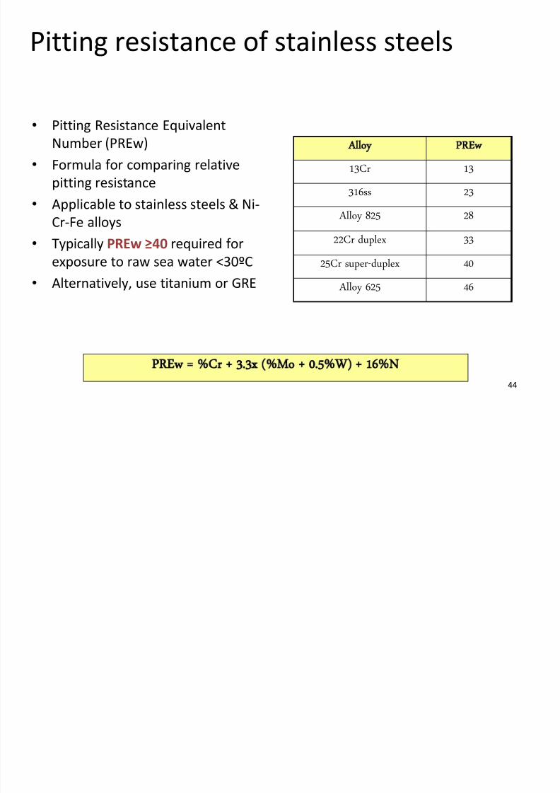
Pitting resistance of stainless steels
• Pitting Resistance Equivalent
Number (PREw)
• Formula for comparing relative
pitting resistance
• Applicable to stainless steels & Ni-
Cr-Fe alloys
• Typically PREw ≥40 required for
exposure to raw sea water <30ºC
•
Alternatively, use titanium or GRE
Alloy PREw
13Cr 13
316ss 23
Alloy 825 28
22Cr duplex 33
25Cr super-duplex 40
Alloy 625 46
PREw = %Cr + 3.3x (%Mo + 0.5%W) + 16%N

7/28/2019 Corrosion in Oil Gas
http://slidepdf.com/reader/full/corrosion-in-oil-gas 45/108
45
Internal & external pitting
• Section of 3” 316L pipe fitting
• Failed due to internal corrosion (pinhole leak)
• Poor hydrotest practice - seawater left within spool
Internal pitting
Failure of a seawater pump cooling

7/28/2019 Corrosion in Oil Gas
http://slidepdf.com/reader/full/corrosion-in-oil-gas 46/108
46
Failure of a seawater pump cooling
coil……
• 316 SS coil, raw seawater service, hypochlorite added
• Shellside: lube oil up to 50°C
• Tubeside: seawater inlet ~6°C, return ~18°C
• Failed due to localised internal pitting
– 316 SS has low PREw
• Material upgrade required
Internal surface of coilxternal surface of coilndication on coil

7/28/2019 Corrosion in Oil Gas
http://slidepdf.com/reader/full/corrosion-in-oil-gas 47/108
47
Oxygen - concentration cells
• Crevice corrosion
– O2 is consumed in the crevice andbecomes the anode
– pH decreases in the crevice increasingattack
• Differential aeration cells
– Air/water interfaces with attack belowthe water line e.g. splash zone
– Pipelines in soils containing differentamounts of oxygen
• Under deposit corrosion
– Deposits of scale, sand or sludge
– Produces differential concentration
– SRBs thrive - H2S pitting
Crevice corrosion under
baffle

7/28/2019 Corrosion in Oil Gas
http://slidepdf.com/reader/full/corrosion-in-oil-gas 48/108
48
Galvanic corrosion
• Three conditions are required for galvanic corrosion;
– A conducting electrolyte (typically seawater).
– Two different metals in contact with the electrolyte.
– An electrical connection between the two metals.
•
Relative positions within the electrochemical series (for givenelectrolyte) provides driving potential and affects rate.
• Corrosion of base metal (anode) stimulated by contact with noblemetal (cathode).
• Relative area of anode and cathode can significantly affectcorrosion rate.
• Higher conductivity increases corrosion e.g. presence of salts

7/28/2019 Corrosion in Oil Gas
http://slidepdf.com/reader/full/corrosion-in-oil-gas 49/108
49
Galvanic corrosion – firewater piping
•Firewater – CuNi / super duplexstainless steel connections.
• 4”CuNi pipe with a 550mm isolation
spool (i.e. 5x OD)
• Leaks experienced on CuNi spools
at welds• Same problems with CuNi / 6Mo

7/28/2019 Corrosion in Oil Gas
http://slidepdf.com/reader/full/corrosion-in-oil-gas 50/108
50
Galvanic corrosion - seal rings
• ETAP platform
• Techlok joints in a firewater
piping system
– Piping: super-duplex
– Seal rings: 17-4PH

7/28/2019 Corrosion in Oil Gas
http://slidepdf.com/reader/full/corrosion-in-oil-gas 51/108
51
• Brass tubesheet in seawater
service
– Brass is Cu-Zn alloy
– Cu is more noble than Zn
–
Zn dissolves preferentiallyleaving Cu behind
• Result
– Loss of strength
– Difficult to seal
• Remedy
– Add arsenic to the brass
Dealloying of brass

7/28/2019 Corrosion in Oil Gas
http://slidepdf.com/reader/full/corrosion-in-oil-gas 52/108
52
Mitigation of galvanic corrosion
• Avoid dissimilar materials in
seawater system designs
– MoC for later changes
• Avoid small anode/large
cathode
• Avoid graphite gaskets & seals
• Avoid connecting carbon steel
to titanium alloys
– Galvanic corrosion or
hydrogen charging of titanium may occur
• Electrical isolation between different
alloy classes
• Install distance spools, separation of
at least 20x pipe diameters
– Solid non-conducting spool e.g.
GRP
– Line the noble metal internally
with an electrically non-
conducting material e.g. rubber
• Apply a non-conducting internal
coating on the more noble material.
Extend coating for 20 pipe diameters.

7/28/2019 Corrosion in Oil Gas
http://slidepdf.com/reader/full/corrosion-in-oil-gas 53/108
53
Example : CuNi-Super duplex
Apply a non-conducting internal coating on the more noble material.
Distance spool: solid, non-conducting material e.g. GRP
Distance spool: noble metal internally lined with an electrically non-conducting material such as rubber

7/28/2019 Corrosion in Oil Gas
http://slidepdf.com/reader/full/corrosion-in-oil-gas 54/108
54
Cathodic protection (CP) – what is it?
•By connecting an external anode to the component to be protected andpassing a dc current, it becomes cathodic and does not corrode.
– External anode may be a galvanic (sacrificial) anode, the current is
the result of the potential difference between the two metals
– External anode may be an impressed current anode, current is
supplied from an external dc power source.• CP is mostly applied to coated, immersed and buried structures
– The coating is the primary protection, acting as a barrier between the
metal and the environment
– CP protects steel at coating defects
• Coating + CP is most practical and economic protection system.
– Primary principle in GP 06-31
Cathodic protection – how does it
7/28/2019 Corrosion in Oil Gas
http://slidepdf.com/reader/full/corrosion-in-oil-gas 55/108
55
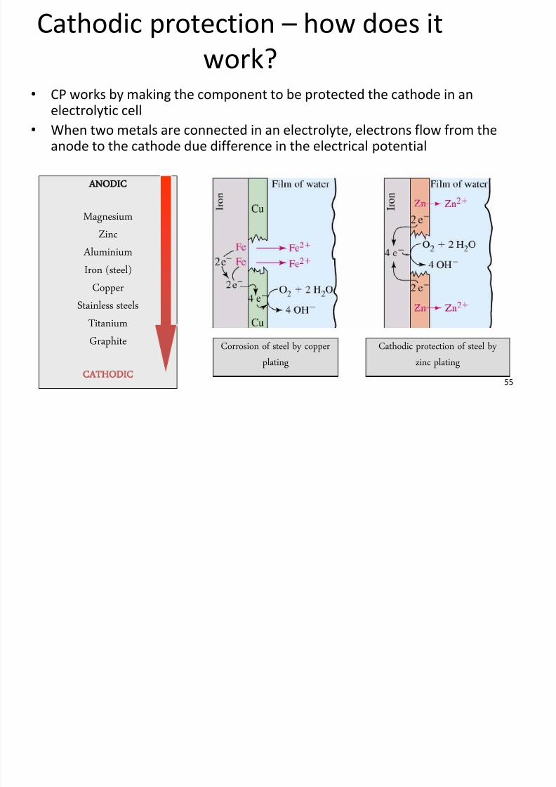
Cathodic protection how does it
work?
ANODIC
Magnesium
Zinc
Aluminium
Iron (steel)
CopperStainless steels
Titanium
Graphite
CATHODIC
Corrosion of steel by copper
plating
Cathodic protection of steel by
zinc plating
•
CP works by making the component to be protected the cathode in anelectrolytic cell
• When two metals are connected in an electrolyte, electrons flow from theanode to the cathode due difference in the electrical potential

7/28/2019 Corrosion in Oil Gas
http://slidepdf.com/reader/full/corrosion-in-oil-gas 56/108
56
Galvanic (sacrificial) CP
• Aluminium anodes: require alloy additions tobecome active e.g. Zn + In, high efficiency (>90%).
– Typically used in seawater applications.
• Zinc anodes: ambient applications only. Alloyedwith Al or Cd to improve efficiency.
– Typically used on coated pipelines in seawater
• Magnesium anodes: large driving potential,alloyed with e.g. Al or Zn to reduce rapidactivation, limited efficiency (50-60%)
– Used in soils and other high-resistanceenvironments (risk of over-protection/rapid
consumption in seawater).
Sacrificial anodes, new and wasted
(therefore working!)

7/28/2019 Corrosion in Oil Gas
http://slidepdf.com/reader/full/corrosion-in-oil-gas 57/108
57
Applications of internal CP
• Anodes in shell & tube seawater
cooler water boxes
•
Oil storage tanks (in water bottom)• Water tanks
•Stainless steel piping systems in warm/hot chlorinated seawater.
−To avoid high anode consumption rates, resistor controlled CP (RCP) systems should be considered.
−E.g. RCP + 25Cr super duplex piping instead of titanium or other higher-alloy CRA.
−Used on Greater Plutonio
Chloride stress corrosion cracking
7/28/2019 Corrosion in Oil Gas
http://slidepdf.com/reader/full/corrosion-in-oil-gas 58/108
58
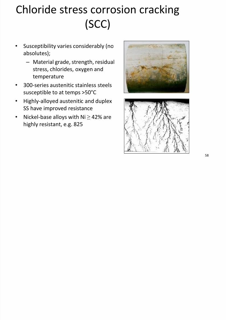
Chloride stress corrosion cracking
(SCC)
• Susceptibility varies considerably (no
absolutes);
– Material grade, strength, residual
stress, chlorides, oxygen and
temperature• 300-series austenitic stainless steels
susceptible to at temps >50°C
• Highly-alloyed austenitic and duplex
SS have improved resistance
• Nickel-base alloys with Ni ≥ 42% arehighly resistant, e.g. 825
Chloride SCC (22Cr duplex vessel

7/28/2019 Corrosion in Oil Gas
http://slidepdf.com/reader/full/corrosion-in-oil-gas 59/108
59
Chloride SCC (22Cr duplex vessel
drain)
• 22Cr duplex drain ex-production separator
− heat-traced to 60°C (vessel temp up to 105°C)
• Internal chloride SCC (cracking in parent metal, HAZ and weld metal)
• Contributory factors:
− Susceptible material
− Local stress concentration (weld toe and lack of support)
− Environment (elevated temperature, chlorides).

7/28/2019 Corrosion in Oil Gas
http://slidepdf.com/reader/full/corrosion-in-oil-gas 60/108
60
Water injection systems (deaerated)Oxygen:
• Trace amounts corrosive to carbon
steel. As a guide:
– <20ppb O2 maintains general
corrosion rates <0.25mm/yr
– Stricter limits often applied e.g.
<10ppb if 13Cr completions
Microbial-induced Corrosion, MIC
• SRB require anaerobic conditions
– deaerated water
– conditions within and underbiofilms
• SRB use sulphate in water in their
metabolisms to generate H2S
Fluid Velocity:
• Areas of high fluid velocity orturbulence and O2
– O2 from poor deaeration or airingress
– susceptible areas include pump
discharge piping, bends teesand reducers.
7/28/2019 Corrosion in Oil Gas
http://slidepdf.com/reader/full/corrosion-in-oil-gas 61/108
61
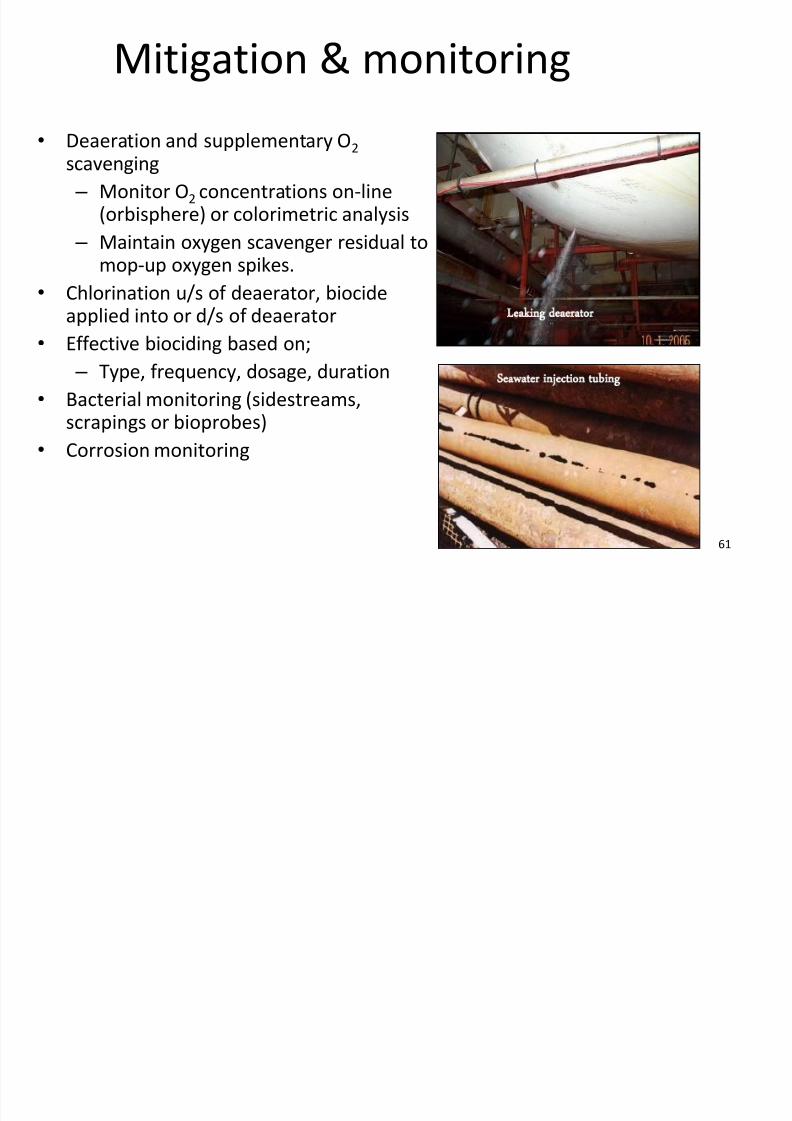
Mitigation & monitoring
•Deaeration and supplementary O2 scavenging
– Monitor O2 concentrations on-line(orbisphere) or colorimetric analysis
– Maintain oxygen scavenger residual tomop-up oxygen spikes.
• Chlorination u/s of deaerator, biocideapplied into or d/s of deaerator
• Effective biociding based on;
– Type, frequency, dosage, duration
• Bacterial monitoring (sidestreams,scrapings or bioprobes)
• Corrosion monitoring
Leaking deaerator
Seawater injection tubing

7/28/2019 Corrosion in Oil Gas
http://slidepdf.com/reader/full/corrosion-in-oil-gas 62/108
62
Preferential weld corrosion (PWC)
• The selective corrosion of weld zones (WM/HAZ)
• Relevant factors include;
– Electrochemical properties of the materials and any corrosion cell
forming around the weld joint
–
Water phase liquid film thickness and conductivity – Temperature and tendency to form protective scale
– Corrosion inhibitor effectiveness, (film formation, composition)
– Weld joint metallurgy
– Flow pattern and flow induced shear stress
• PWC rate of attack can be high, up to 12mm/yr observed

7/28/2019 Corrosion in Oil Gas
http://slidepdf.com/reader/full/corrosion-in-oil-gas 63/108
63
Preferential weld corrosion (1%Ni)Water Injection:
• 1% Ni-containing weldsbeneficial for avoiding PWC inWI systems.
• Weld cathodic to parentmetal, protected by large area
of parent metal.
Wet hydrocarbon service:
• Lower conductivity, no benefit of selecting ‘cathodic’ weld metal
• Reliant on intrinsic corrosion resistanceof the weld metal
• Require corrosion inhibitor for
protection (test against WM and PM)• Attack of weld metal promoted by
under-dosing of inhibitor (WM needsmore inhibitor than PM)
Welds exposed to hydrocarbon service
L d d i PWC

7/28/2019 Corrosion in Oil Gas
http://slidepdf.com/reader/full/corrosion-in-oil-gas 64/108
64
Lomond drains - PWC
• TEG contactor scrubber drain
pipework (hydrocarbon)
• Carbon steel parent metal
• ~2%Ni deposited in weld metal
• Groove along 6 o’clock position
• Accelerated corrosion at the weld
• Large number of isolations,
extensive inspection and repair

7/28/2019 Corrosion in Oil Gas
http://slidepdf.com/reader/full/corrosion-in-oil-gas 65/108
65
MIC & DEADLEG CORROSION
Mi bi ll i d d i (MIC)
7/28/2019 Corrosion in Oil Gas
http://slidepdf.com/reader/full/corrosion-in-oil-gas 66/108
66
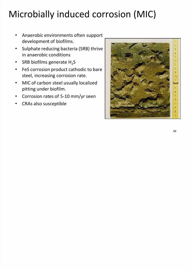
Microbially induced corrosion (MIC)
• Anaerobic environments often supportdevelopment of biofilms.
• Sulphate reducing bacteria (SRB) thrive
in anaerobic conditions
• SRB biofilms generate H2S
• FeS corrosion product cathodic to bare
steel, increasing corrosion rate.
• MIC of carbon steel usually localized
pitting under biofilm.
• Corrosion rates of 5-10 mm/yr seen
• CRAs also susceptible

7/28/2019 Corrosion in Oil Gas
http://slidepdf.com/reader/full/corrosion-in-oil-gas 67/108
67
Bacterial growth factors
•
pHMIC growth in pH 5-9.5 range
• Temperature
SRB can grow in temps of 5-
100°C. Optimum temp
<45ºC.
• Sulphates
– Necessary for SRB activity.
– Growth restricted if <10 ppm
• Carbon source SRB growth restricted if organic
carbon (volatile fatty acids)
not available (<20ppm)
• Nitrogen
Important but at levels which
are difficult to detect
• Flow
– Highest corrosion rates in
stagnant conditions.
– Biofilms unstable at high
flows.
D dl t & l ti

7/28/2019 Corrosion in Oil Gas
http://slidepdf.com/reader/full/corrosion-in-oil-gas 68/108
68
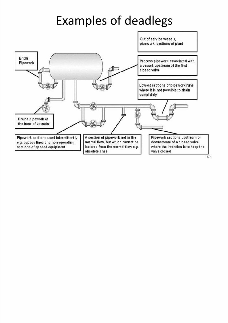
Deadlegs – types & locations
• A deadleg is a section of pipework or vessel which contains hydrocarbonfluids and/or water under
– stagnant conditions (permanent or intermittent)
– or where there is no measurable flow.
• Permanent or physical deadlegs (long term stagnation by design)
• Operational deadlegs (stagnant for operational reasons)• Unprotected mothballed items (plus those temporarily out of service)
7/28/2019 Corrosion in Oil Gas
http://slidepdf.com/reader/full/corrosion-in-oil-gas 69/108
69
Examples of deadlegs
7/28/2019 Corrosion in Oil Gas
http://slidepdf.com/reader/full/corrosion-in-oil-gas 70/108
70
Deadlegs – assessment factors
• Consequence of failure• Location of pipework
• Nutrients replenished by regularly opening /closing valves?
• Is draining of pipework possible?
• Is removal of deadleg possible?
•
Presence of SRBs, deposits, biocide?• Material of construction
• Wall thickness
• Fluid type (aqueous phase, sulphates, nutrients, oxygen ingress)
• Temperature
• Stagnant – permanent/intermittent
• Prior history of corrosion
E l f d dl i

7/28/2019 Corrosion in Oil Gas
http://slidepdf.com/reader/full/corrosion-in-oil-gas 71/108
71
Example of deadleg corrosion
•
Crude oil recycle cooler bypass• Scale-inhibited seawater left in line after leak test (of u/s valve)
• Severe corrosion rate at and around pinhole.
• Fortunately, a leak of water not crude.
• Two week shutdown
Pin Hole leaks
Releasing water
Pin Hole leaks
Releasing water
R t

7/28/2019 Corrosion in Oil Gas
http://slidepdf.com/reader/full/corrosion-in-oil-gas 72/108
72
Root causes
110mm
80mm
Area of internal corrosion
reading from 3.5 mm
tapering out to average of
10.7mm
Area of internal
corrosion 4.2 mm
tapering out to
average wall
thickness of 10.0 mm
VIEW LOOKING WEST
Photo1
North
30mm
250mm
Corroded area approx 80mm x 110mm.
• Failure to identify the bypass line as an operational
deadleg
• No deadleg register
• Failure to recognise introduction of new corrosion
hazard
• No mitigation measures.
Miti ti & i ti

7/28/2019 Corrosion in Oil Gas
http://slidepdf.com/reader/full/corrosion-in-oil-gas 73/108
73
Mitigation & inspection
• Flush system of deposits and treat with
biocide, nitrate
• Out of service items
– Biocide treat or mothball procedure
• Use treated water – Hydrotest & washing
• Profile radiography or UT scanning
– low points, bottom of vertical
sections etc.
• Lowest parts of vessel bridle together
with any associated level gauges.

7/28/2019 Corrosion in Oil Gas
http://slidepdf.com/reader/full/corrosion-in-oil-gas 74/108
74
OTHER CORROSION MECHANISMS

7/28/2019 Corrosion in Oil Gas
http://slidepdf.com/reader/full/corrosion-in-oil-gas 75/108
75
Corrosion due to chemicals
• Chemicals can be corrosive • Carbon steel OK for non-corrosive chemical
piping, e.g. methanol
• Corrosive chemicals (e.g. concentrated
solutions of inhibitors and biocides) require
CRAs – vendor will specify – 316 SS is typical
• Notable exceptions:
– Hypochlorite: very corrosive, titanium or GRP
piping required
– Avoid titanium alloys in dry methanol servicedue SCC SCC of a titanium seal exposed to
pure methanol instead of 5%
water content
Corrosion due to chemicals

7/28/2019 Corrosion in Oil Gas
http://slidepdf.com/reader/full/corrosion-in-oil-gas 76/108
76
Corrosion due to chemicals
• Carbon steel open drain pipework.
• Seepage of scale inhibitor (passing valve)
• Scale inhibitor pH <2.
• Chemical entered drains, not flushed
Injection point issues

7/28/2019 Corrosion in Oil Gas
http://slidepdf.com/reader/full/corrosion-in-oil-gas 77/108
77
Injection point issues
• Inadequate mixing – corrosion
• Intermittent use
– switch off when not flowing
• Areas affected
– Impingement / turbulent areas
– Bends and low points• Use quill/other mixer
– Upgrade material
– Thicker schedule
• Valve arrangement
–
Make self-draining – Enable quill removal
Main Flow
Injected Fluid
Impingement
High temperature corrosion
7/28/2019 Corrosion in Oil Gas
http://slidepdf.com/reader/full/corrosion-in-oil-gas 78/108
78
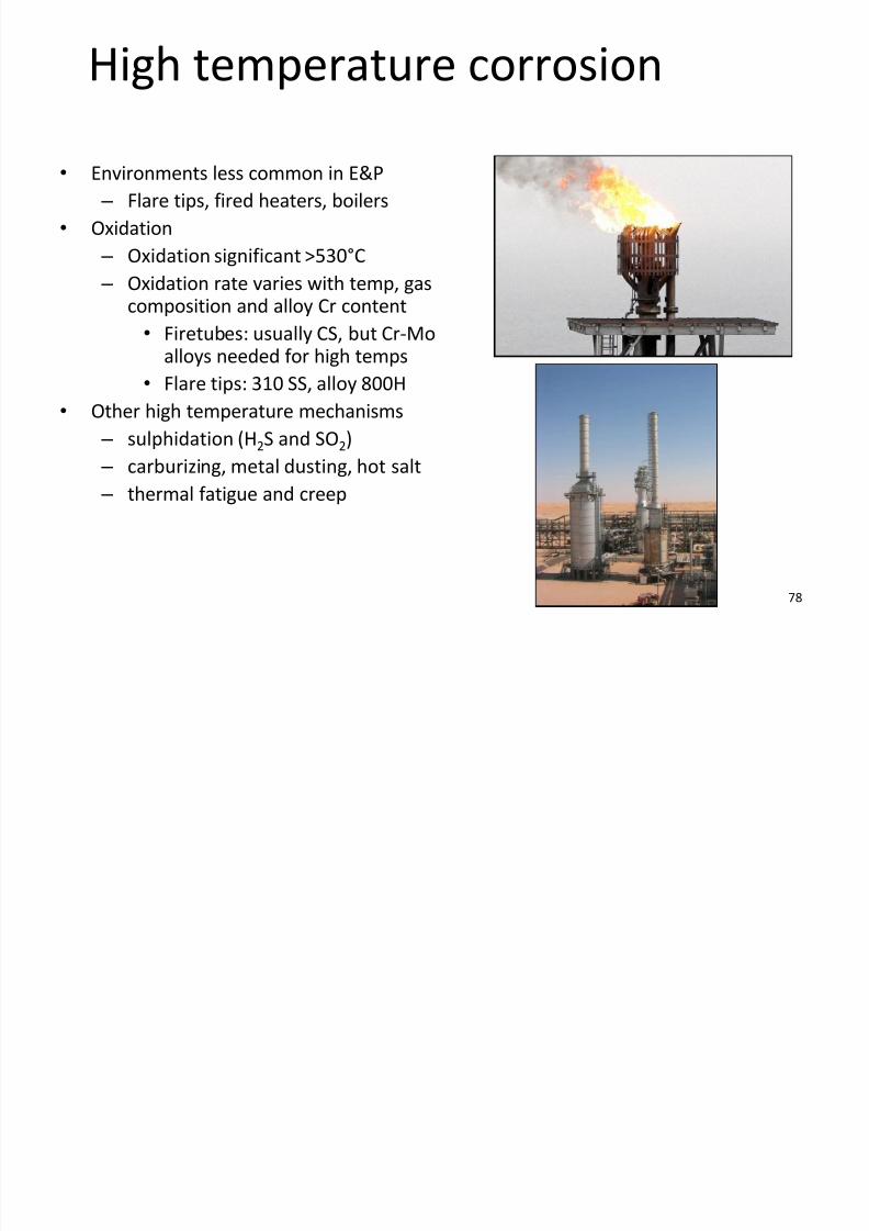
High temperature corrosion
• Environments less common in E&P
– Flare tips, fired heaters, boilers
• Oxidation
– Oxidation significant >530°C
– Oxidation rate varies with temp, gas
composition and alloy Cr content• Firetubes: usually CS, but Cr-Mo
alloys needed for high temps
• Flare tips: 310 SS, alloy 800H
• Other high temperature mechanisms
– sulphidation (H2S and SO2)
– carburizing, metal dusting, hot salt
– thermal fatigue and creep
Amine stress corrosion cracking

7/28/2019 Corrosion in Oil Gas
http://slidepdf.com/reader/full/corrosion-in-oil-gas 79/108
79
Amine stress corrosion cracking
• Material: carbon/low-alloy steels
• Environment: aqueous amine systems
• Cracking due to residual stresses at/next to
non-PWHT’d weldments
–
Cracking develops parallel to the weld• Mitigation:
– PWHT all CS welds including repair and
internal/external attachment welds.
– Use solid/clad stainless steel
• 304 SS or 316 SS
Intergranular cracking
Amine piping welds require
PWHT to avoid SCC
Corrosion in glycol system

7/28/2019 Corrosion in Oil Gas
http://slidepdf.com/reader/full/corrosion-in-oil-gas 80/108
80
Corrosion in glycol system
•
Glycol usually regarded as benign• Corrosion in glycol regeneration systems
usually due to;
– Acid gases absorbed by rich glycol or
– Organic acids from oxidation of glycol
and thermal decomposition products• Condensation of low pH water giving
carbonic acid attack.
• Risk recognised in design
– On-skid: CRA piping & clad vessels
– However, off-skid piping mix of regular
CS and LTCS
Corrosion fatigue

7/28/2019 Corrosion in Oil Gas
http://slidepdf.com/reader/full/corrosion-in-oil-gas 81/108
81
Corrosion fatigue
• Combined action of cyclic tensile stressand a corrosive environment
• Fatigue is caused by cyclic stressingbelow the yield stress
– Cracks start at stress raisers
– Can occur due to vibration e.g.smallbore nozzles & with heavyvalve attachments
• Presence of corrosive environmentexacerbates the problem
– Can lead to pitting, which acts asstress concentrators
Example of corrosion fatigue
7/28/2019 Corrosion in Oil Gas
http://slidepdf.com/reader/full/corrosion-in-oil-gas 82/108
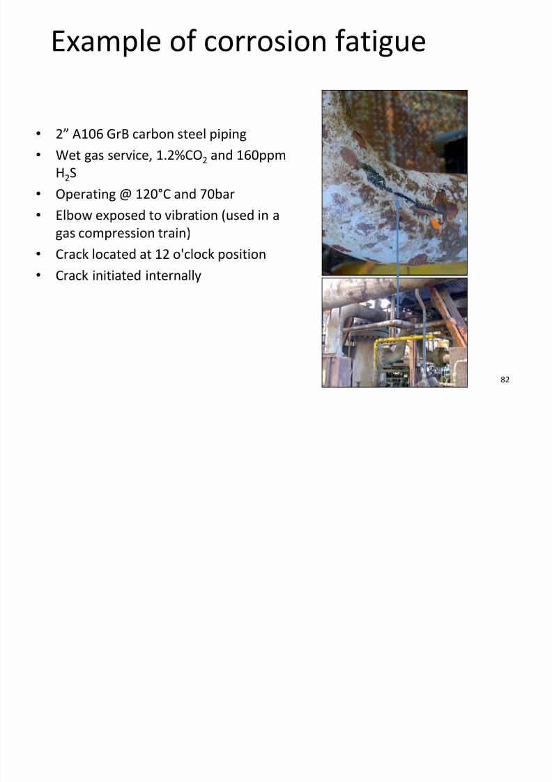
82
Example of corrosion fatigue
• 2” A106 GrB carbon steel piping
• Wet gas service, 1.2%CO2 and 160ppm
H2S
•Operating @ 120°C and 70bar
• Elbow exposed to vibration (used in a
gas compression train)
• Crack located at 12 o'clock position
• Crack initiated internally

7/28/2019 Corrosion in Oil Gas
http://slidepdf.com/reader/full/corrosion-in-oil-gas 83/108
83
EXTERNAL CORROSION – SURFACEFACILITIES
E l i

7/28/2019 Corrosion in Oil Gas
http://slidepdf.com/reader/full/corrosion-in-oil-gas 84/108
84
External corrosion
• External corrosion of unprotected steel surfaces
• External corrosion of coated surfaces
• Corrosion under insulation (CUI)
• Corrosion under fireproofing (CUF)
• Pitting & crevice Corrosion
• Environmental cracking
Wh d it ?

7/28/2019 Corrosion in Oil Gas
http://slidepdf.com/reader/full/corrosion-in-oil-gas 85/108
85
Where does it occur?• Bare steel surfaces
• At locations of coating breakdown
• Under deposits such as dirt, adhesive tape or nameplates
• Mating faces between pipe/pipe support saddles & clamps
• Isolated equipment not maintained or adequately mothballed
• Water sources include:
– sea spray and green water (FPSO or semi-sub)
– rain
– deluge water
– leaking process water
–
condensation – downwind of cooling towers.
What does it look like?

7/28/2019 Corrosion in Oil Gas
http://slidepdf.com/reader/full/corrosion-in-oil-gas 86/108
86
What does it look like?
• Damage can be extensive or localised.
•
Corrosion can be general attack, pitting or cracking.• Seen as flaking, cracking, and blistering of coating with corrosion
of the substrate.
Appearance

7/28/2019 Corrosion in Oil Gas
http://slidepdf.com/reader/full/corrosion-in-oil-gas 87/108
87
Appearance
•Carbon/low alloy steels usuallycovered in compact scale/thick scab
• Stainless steels have light stains on the
surface possibly with stained water
droplets and / or salts.
• Corroding copper alloys covered inblue/green corrosion products.
Piping supports & clamps
7/28/2019 Corrosion in Oil Gas
http://slidepdf.com/reader/full/corrosion-in-oil-gas 88/108
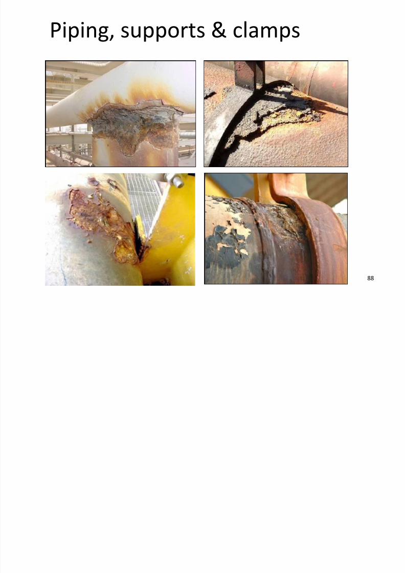
88
Piping, supports & clamps
Not just carbon steel
7/28/2019 Corrosion in Oil Gas
http://slidepdf.com/reader/full/corrosion-in-oil-gas 89/108
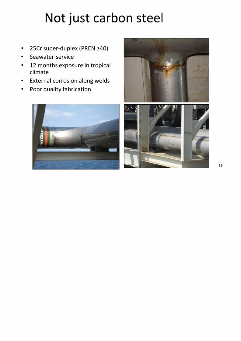
89
Not just carbon steel
• 25Cr super-duplex (PREN ≥40)
• Seawater service
• 12 months exposure in tropicalclimate
• External corrosion along welds
• Poor quality fabrication
C i f b lt d f t

7/28/2019 Corrosion in Oil Gas
http://slidepdf.com/reader/full/corrosion-in-oil-gas 90/108
90
Corrosion of bolts and fasteners
• Bolted joints
– Onshore and offshore: exposed to frequent wetting
• Low alloy bolts
– General or localised corrosion
–
Galvanic corrosion in stainless steel flanges• CRA bolts susceptible to pitting and/or SCC
• Crevice corrosion under bolt heads and nuts
• Hydrogen embrittlement possible
• Fatigue
Corrosion of bolts and fasteners

7/28/2019 Corrosion in Oil Gas
http://slidepdf.com/reader/full/corrosion-in-oil-gas 91/108
91
Corrosion of bolts and fasteners
General corrosion Galvanic corrosion
Crevice corrosion Stress corrosion cracking
Flanged connections

7/28/2019 Corrosion in Oil Gas
http://slidepdf.com/reader/full/corrosion-in-oil-gas 92/108
92
Flanged connections
• Corrosion
– General surface corrosion
– Galvanic corrosion
• e.g. 316 SS / carbon steel
• Use of graphite gaskets
• Potential problems
– Failure of flanged connection due tocorroded fasteners
– Joint leak
• Corrective actions
– Change gasket/fastener materials
–Replace graphite gaskets with non-asbestos or rubber material
Corroded fasteners (seawater service)

7/28/2019 Corrosion in Oil Gas
http://slidepdf.com/reader/full/corrosion-in-oil-gas 93/108
93
Corroded fasteners (seawater service)
Location of graphite gaskets
Structures / valves
7/28/2019 Corrosion in Oil Gas
http://slidepdf.com/reader/full/corrosion-in-oil-gas 94/108
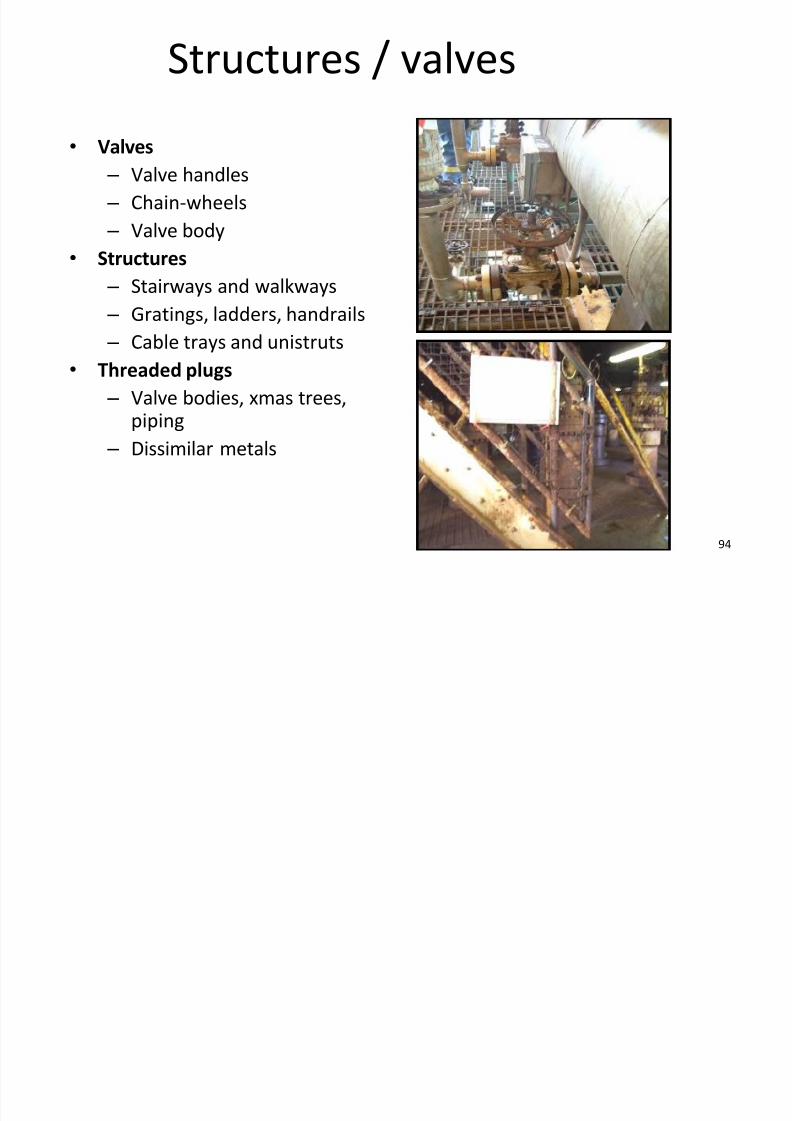
94
Structures / valves
•Valves – Valve handles
– Chain-wheels
– Valve body
• Structures
– Stairways and walkways – Gratings, ladders, handrails
– Cable trays and unistruts
• Threaded plugs
– Valve bodies, xmas trees,
piping
– Dissimilar metals
Coating damage and breakdown
7/28/2019 Corrosion in Oil Gas
http://slidepdf.com/reader/full/corrosion-in-oil-gas 95/108
95
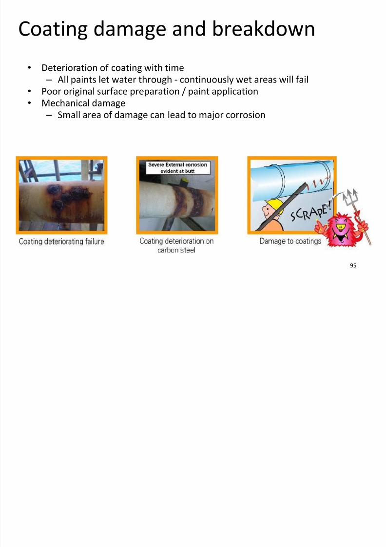
Coating damage and breakdown
•
Deterioration of coating with time – All paints let water through - continuously wet areas will fail
• Poor original surface preparation / paint application
• Mechanical damage
– Small area of damage can lead to major corrosion
External cathodic protection

7/28/2019 Corrosion in Oil Gas
http://slidepdf.com/reader/full/corrosion-in-oil-gas 96/108
96
External cathodic protection
• Types of structures with external CP – Buried pipelines / structures / piping
/ tanks
– Floors of above-ground storage tanks
– Submerged jetty structures
• Factors affecting corrosion
– Extent of wetness
– Oxygen – depends on depth
– Resistivity of soil & presence of salts
– Equipment temperature
Impressed current CP
7/28/2019 Corrosion in Oil Gas
http://slidepdf.com/reader/full/corrosion-in-oil-gas 97/108
97
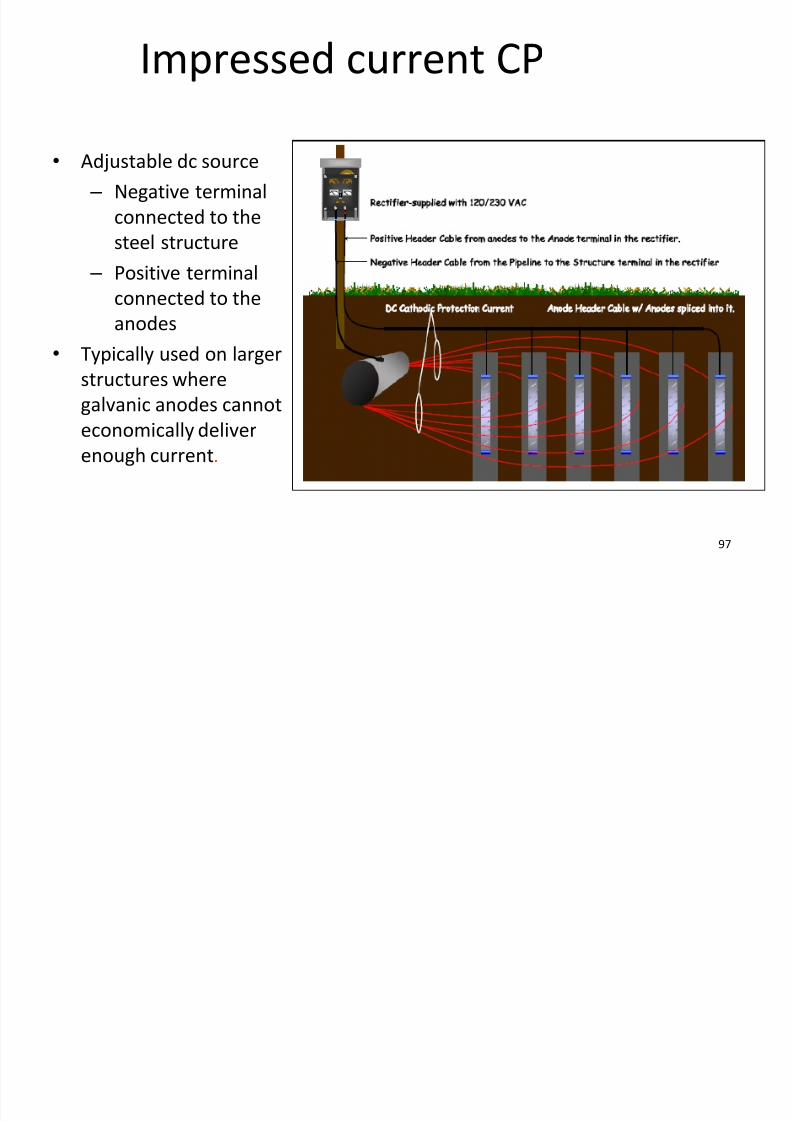
Impressed current CP
• Adjustable dc source
– Negative terminal
connected to the
steel structure
–
Positive terminalconnected to the
anodes
• Typically used on larger
structures where
galvanic anodes cannot
economically deliver
enough current.
Corrosion under insulation (CUI) and
d f f ( )

7/28/2019 Corrosion in Oil Gas
http://slidepdf.com/reader/full/corrosion-in-oil-gas 98/108
98
Corrosion under fireproofing (CUF)
• CUI
– Water seeps into insulation and
becomes trapped, results in
wetting and corrosion of the metal
–
Carbon steel corrodes in thepresence of water due to the
availability of oxygen.
• CUF
– Same mechanism except water
gets behind the fireproofing.
Insulation

7/28/2019 Corrosion in Oil Gas
http://slidepdf.com/reader/full/corrosion-in-oil-gas 99/108
99
Insulation
•Typical insulation types; – Process
– Personnel protection (PP)
– Winterisation
– Acoustic
• Challenge the need
– Remove unnecessary
insulation
– Replace PP with cages‘Lobster-back’ joint
Mitred joint
Pre-formed bends
CUI incident
7/28/2019 Corrosion in Oil Gas
http://slidepdf.com/reader/full/corrosion-in-oil-gas 100/108
100
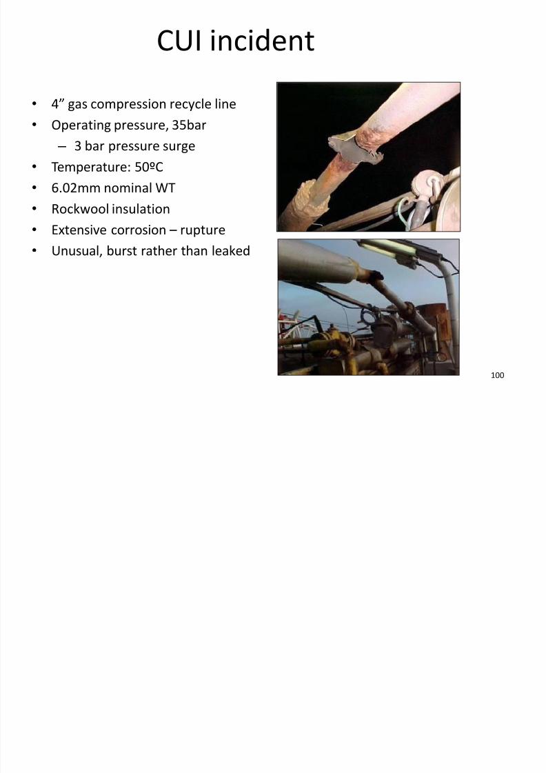
CUI incident
• 4” gas compression recycle line • Operating pressure, 35bar
– 3 bar pressure surge
• Temperature: 50ºC
• 6.02mm nominal WT
• Rockwool insulation
• Extensive corrosion – rupture
• Unusual, burst rather than leaked
CUI gas leak

7/28/2019 Corrosion in Oil Gas
http://slidepdf.com/reader/full/corrosion-in-oil-gas 101/108
101
CUI gas leak
•
2” fuel gas piping outside edgeof platform - exposed
• CS, heat-traced, Rockwool
• Operating @ 5bar, 45°C, 5.4mm
NWT
• Failed during plant start-up• External corrosion scale, CUI
•
Focus on internal corrosion• Previous survey found defect in
an adjacent line.
• Failed line in survey but not
failed area.
– Features selected fromonshore not site survey
piping CUI
7/28/2019 Corrosion in Oil Gas
http://slidepdf.com/reader/full/corrosion-in-oil-gas 102/108
102
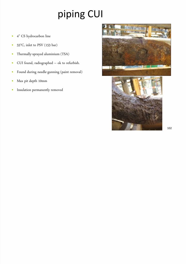
piping CUI
• 4” CS hydrocarbon line
• 55°C, inlet to PSV (153 bar)
• Thermally-sprayed aluminium (TSA)
• CUI found, radiographed – ok to refurbish.
• Found during needle-gunning (paint removal)
• Max pit depth 10mm
• Insulation permanently removed
CUI on pressure vessel
7/28/2019 Corrosion in Oil Gas
http://slidepdf.com/reader/full/corrosion-in-oil-gas 103/108
103
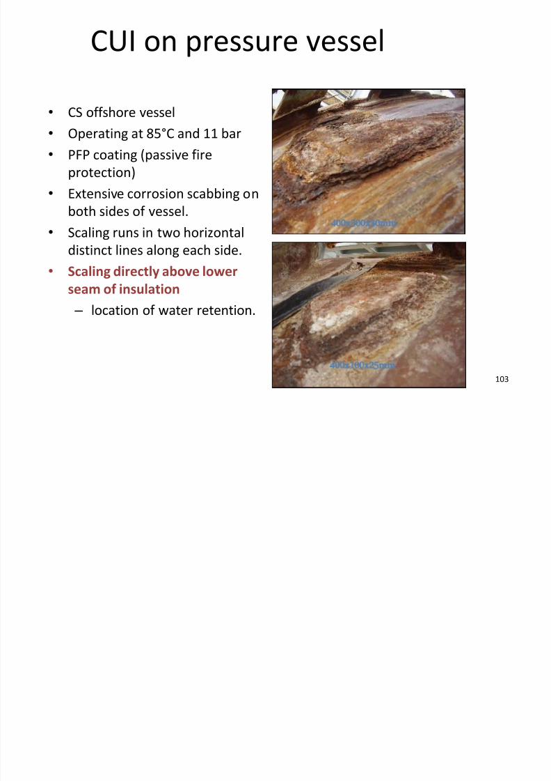
CUI on pressure vessel
• CS offshore vessel
• Operating at 85°C and 11 bar
• PFP coating (passive fire
protection)
•
Extensive corrosion scabbing onboth sides of vessel.
• Scaling runs in two horizontal
distinct lines along each side.
• Scaling directly above lower
seam of insulation – location of water retention.
400x300x30mm
400x100x25mm
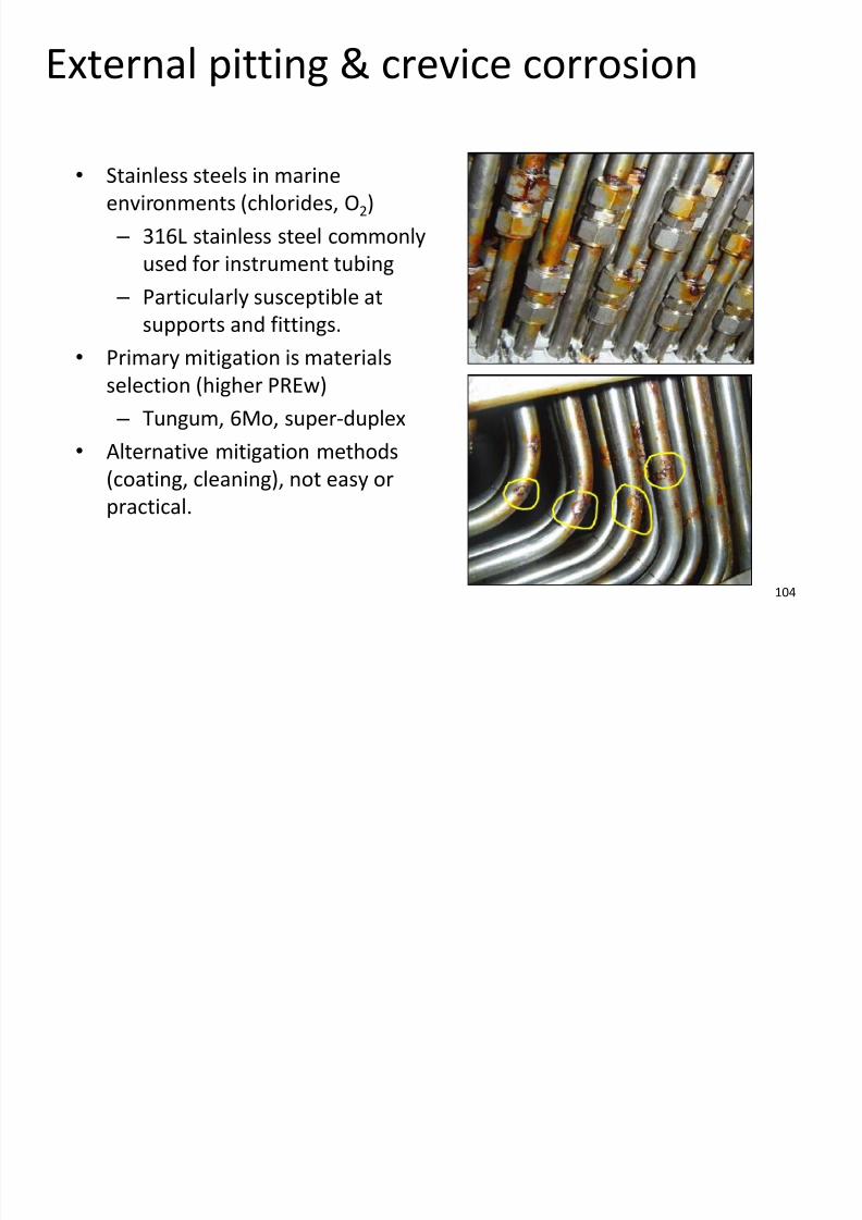
External pitting & crevice corrosion
7/28/2019 Corrosion in Oil Gas
http://slidepdf.com/reader/full/corrosion-in-oil-gas 104/108
104
p g
• Stainless steels in marine
environments (chlorides, O2)
– 316L stainless steel commonly
used for instrument tubing
– Particularly susceptible at
supports and fittings.
• Primary mitigation is materials
selection (higher PREw)
– Tungum, 6Mo, super-duplex
•Alternative mitigation methods(coating, cleaning), not easy or
practical.
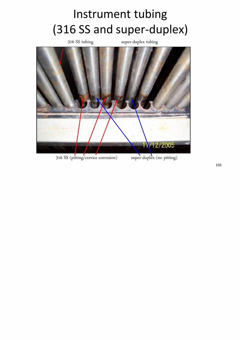
Instrument tubing
7/28/2019 Corrosion in Oil Gas
http://slidepdf.com/reader/full/corrosion-in-oil-gas 105/108
105
(316 SS and super-duplex)316 SS tubing super-duplex tubing
316 SS (pitting/crevice corrosion) super-duplex (no pitting)
Crevice corrosion under
l / t

7/28/2019 Corrosion in Oil Gas
http://slidepdf.com/reader/full/corrosion-in-oil-gas 106/108
106
clamps/supports
• Pitting and crevice
corrosion of 316ss piping
– Clamps
– Plastic retaining blocks
External chloride stress corrosion
ki

7/28/2019 Corrosion in Oil Gas
http://slidepdf.com/reader/full/corrosion-in-oil-gas 107/108
107
cracking
• Mechanism same as internal chloride SCC however:
• Numerous variables influence susceptibility therefore guidancediffers
– Material, stress, chlorides, oxygen and temperature
– No absolute guidance available, seek expert advice
Chloride SCC is characterised by trans-
granular crack paths
External stress corrosion cracking
7/28/2019 Corrosion in Oil Gas
http://slidepdf.com/reader/full/corrosion-in-oil-gas 108/108
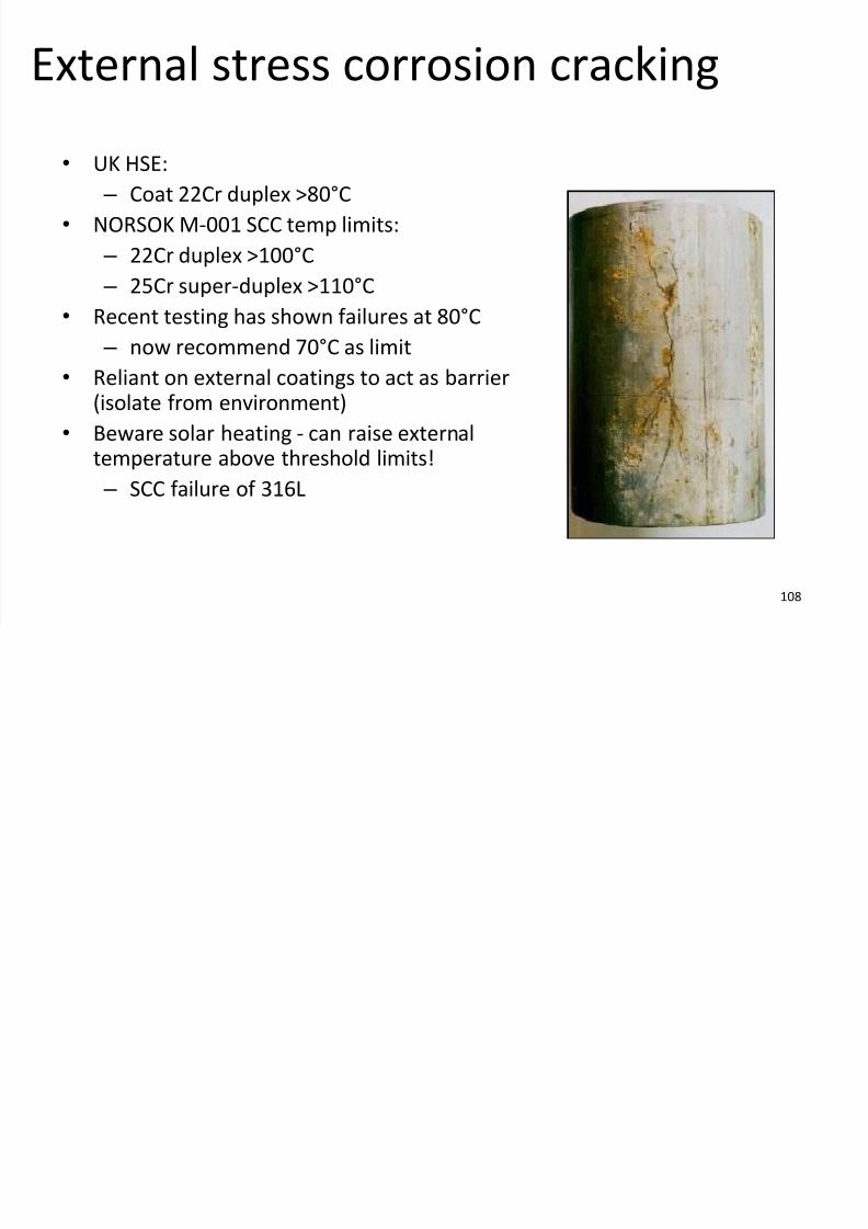
g
•UK HSE: – Coat 22Cr duplex >80°C
• NORSOK M-001 SCC temp limits:
– 22Cr duplex >100°C
– 25Cr super-duplex >110°C
• Recent testing has shown failures at 80°C – now recommend 70°C as limit
• Reliant on external coatings to act as barrier(isolate from environment)
• Beware solar heating - can raise external
temperature above threshold limits! – SCC failure of 316L