control strategy of dc link voltage flywheel energy ... electrical energy, and the dc bus capacitor...
TRANSCRIPT
Journal of Power and Energy Engineering, 2017, 5, 72-79 http://www.scirp.org/journal/jpee
ISSN Online: 2327-5901 ISSN Print: 2327-588X
DOI: 10.4236/jpee.2017.511006 Nov. 28, 2017 72 Journal of Power and Energy Engineering
Control Strategy of DC Link Voltage Flywheel Energy Storage for Non Grid Connected Wind Turbines Based on Fuzzy Control
Arslan Habib1*, Chan Sou2, Adesh Ananta2
¹Northwestern Polytechnical University, Xi’an, China 2State Grid Tianjin Energy Saving Service Co., Ltd., Tianjin, China
Abstract The large-scale development of wind power is an important means to reduce greenhouse gas emissions, alleviate environmental pollution and improve the utilization rate of renewable energy. At the same time, large-scale non grid connected wind power generation theory avoids the technical difficulties of wind power integration [1]. However, due to the randomness and uncontrol-lability of wind energy, the output power of the wind power generation system will fluctuate accordingly [2]. Therefore, the corresponding energy storage devices are arranged in the non-grid-connected wind power generation sys-tem to ensure the power quality, and it has become the key to full utilization of renewable energy. In the case of wind speed fluctuation, the DC bus control strategy of the wind turbine is proposed in this paper. It can reduce the impact on the unit converter and the power load; this ensures safe and stable opera-tion of non-grid connected wind turbines. Keywords Non-Grid Connected Wind Power Generation, DC Bus Voltage, Control Strategy
1. Introduction
Wind power has been recognized by the world, but also the closest to commer-cialization, as a strong market competitiveness of renewable energy technology; because, it occupies less land, less social disputes, environment-friendly, can quickly achieve large-scale and industrialization [3] [4]. The terminal load of large-scale wind power is no longer power grid. The small stand-alone power supply system with the battery is also different, but the wind power is directly
How to cite this paper: Habib, A., Sou, C. and Ananta, A. (2017) Control Strategy of DC Link Voltage Flywheel Energy Storage for Non Grid Connected Wind Turbines Based on Fuzzy Control. Journal of Power and Energy Engineering, 5, 72-79. https://doi.org/10.4236/jpee.2017.511006 Received: August 24, 2017 Accepted: November 25, 2017 Published: November 28, 2017 Copyright © 2017 by authors and Scientific Research Publishing Inc. This work is licensed under the Creative Commons Attribution International License (CC BY 4.0). http://creativecommons.org/licenses/by/4.0/
Open Access
A. Habib et al.
DOI: 10.4236/jpee.2017.511006 73 Journal of Power and Energy Engineering
transported to some high-energy carrying enterprises, 100% energy conversion is realized to solve the problem of wind power utilization that cannot be con-nected to the network. Because the terminal load of non-grid connected wind power generation unit has certain requirements for power quality; so, a control scheme of flywheel energy storage system based on fuzzy control is proposed in this paper. This scheme can stabilize the DC bus voltage of the non-grid con-nected wind turbine, improve the working condition of the unit post converter, and improve the power supply quality to the terminal load.
2. System Composition and Configuration
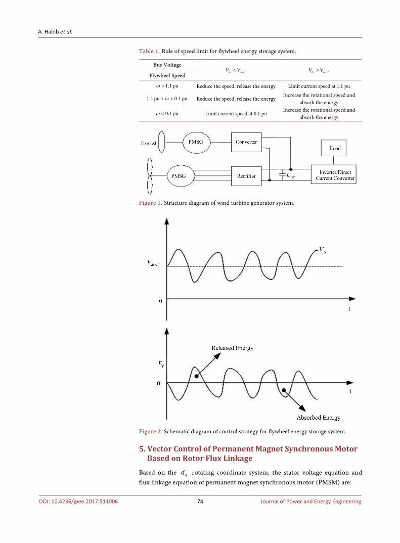
Figure 1 is a structural diagram of a non-grid connected wind turbine generator system supported by flywheel energy storage system. The system consists of flywheel energy storage, variable pitch direct drive wind turbine, converter, load and so on, in which flywheel energy storage system is connected in parallel with DC bus.
3. System Control Strategy
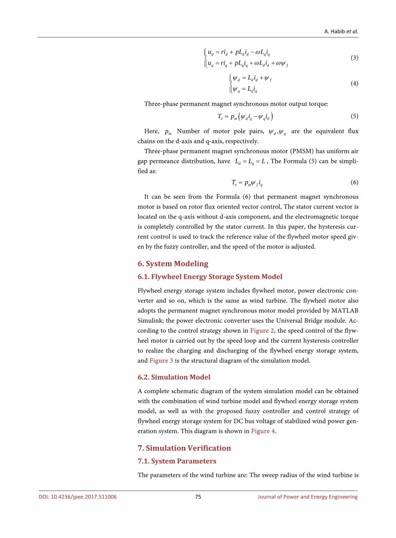
The system control strategy is shown in Figure 2. When dc dcrefV V< , the angular velocity of the flywheel rotor decreases, and the flywheel motor is used as the generator. The flywheel energy storage system converts the mechanical energy into electrical energy, and the DC bus capacitor is provided to improve the DC bus voltage. When dc dcrefV V> , the angular speed of the flywheel rotor rises and the flywheel motor acts as the motor. The flywheel energy storage system ab-sorbs excess energy from the intermediate bus capacitor and convert into me-chanical energy and stored in the flywheel rotor.
4. Speed Limiting Strategy of Flywheel Energy Storage System
Storage of flywheel energy storage system/Released Energy:
( )2 21 12 2
E J Jω ω ω= + ∆ − (1)
Here, J is the inertia moment of flywheel rotor in flywheel energy storage system, ω is Initial value of rotation angular velocity for flywheel, ω∆ is the Change of angular velocity of flywheel. In the control strategy of this paper, the maximum energy storage of flywheel energy storage system is 120% of its rated value, and the maximum and minimum limit of flywheel speed must be satisfied:
2 2 2max min rate1.2ω ω ω− = (2)
Here, max min rate, ,ω ω ω are the maximum, minimum and rated values of flyw-heel speed, respectively. When the maximum speed of the flywheel is 110% (1.1 pu) of the rated speed, the minimum speed of the flywheel determined by the formula is 0.1 pu. The speed limit rules of flywheel energy storage system are shown in Table 1.
A. Habib et al.
DOI: 10.4236/jpee.2017.511006 74 Journal of Power and Energy Engineering
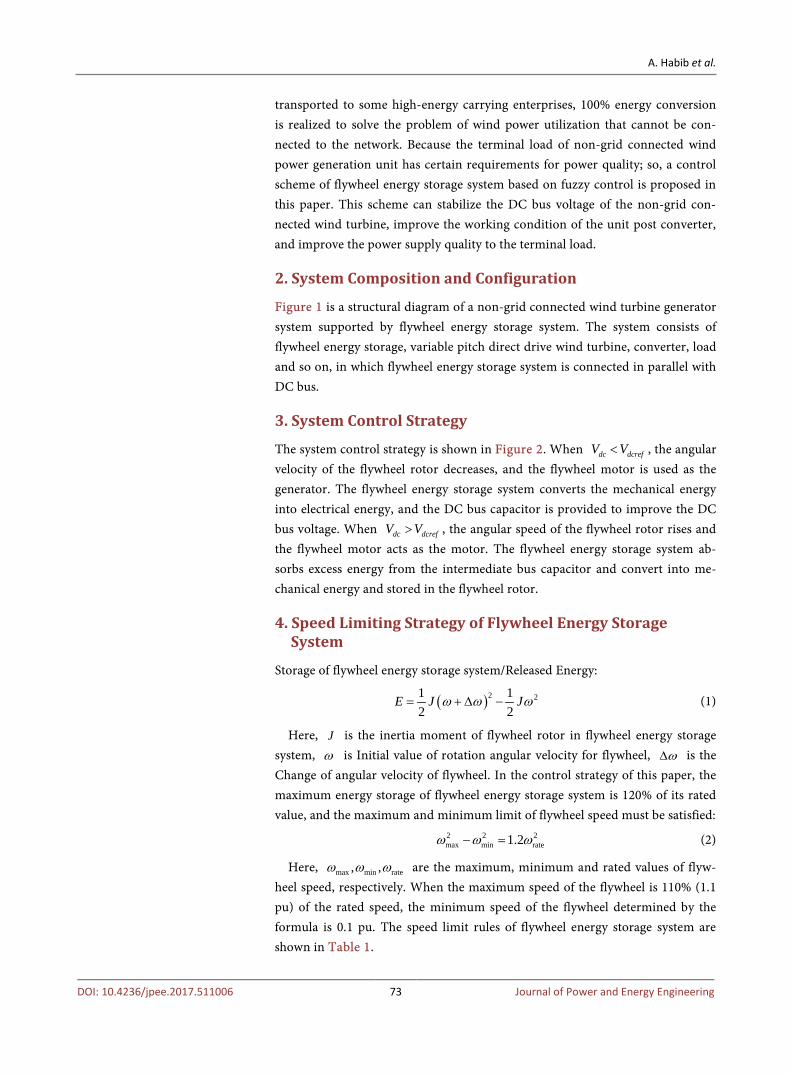
Table 1. Rule of speed limit for flywheel energy storage system.
Bus Voltage dc dcrefV V< dc dcrefV V>
Flywheel Speed
1.1 puω > Reduce the speed, release the energy Limit current speed at 1.1 pu
1.1 pu 0.1 puω> > Reduce the speed, release the energy Increase the rotational speed and
absorb the energy
0.1 puω < Limit current speed at 0.1 pu Increase the rotational speed and
absorb the energy
Figure 1. Structure diagram of wind turbine generator system.
Figure 2. Schematic diagram of control strategy for flywheel energy storage system.
5. Vector Control of Permanent Magnet Synchronous Motor Based on Rotor Flux Linkage
Based on the qd rotating coordinate system, the stator voltage equation and flux linkage equation of permanent magnet synchronous motor (PMSM) are:
A. Habib et al.
DOI: 10.4236/jpee.2017.511006 75 Journal of Power and Energy Engineering
d d d d q q
q q q q d d f
u ri pL i L i
u ri pL i L i
ω
ω ωψ
= + − = + + +
(3)
d d d f
q q q
L i
L i
ψ ψ
ψ
= + =
(4)
Three-phase permanent magnet synchronous motor output torque:
( )e m d q q dT p i iψ ψ= − (5)
Here, mp Number of motor pole pairs, ,d qψ ψ are the equivalent flux chains on the d-axis and q-axis, respectively.
Three-phase permanent magnet synchronous motor (PMSM) has uniform air gap permeance distribution, have d qL L L= = , The Formula (5) can be simpli-fied as:
e m f qT p iψ= (6)
It can be seen from the Formula (6) that permanent magnet synchronous motor is based on rotor flux oriented vector control, The stator current vector is located on the q-axis without d-axis component, and the electromagnetic torque is completely controlled by the stator current. In this paper, the hysteresis cur-rent control is used to track the reference value of the flywheel motor speed giv-en by the fuzzy controller, and the speed of the motor is adjusted.
6. System Modeling 6.1. Flywheel Energy Storage System Model
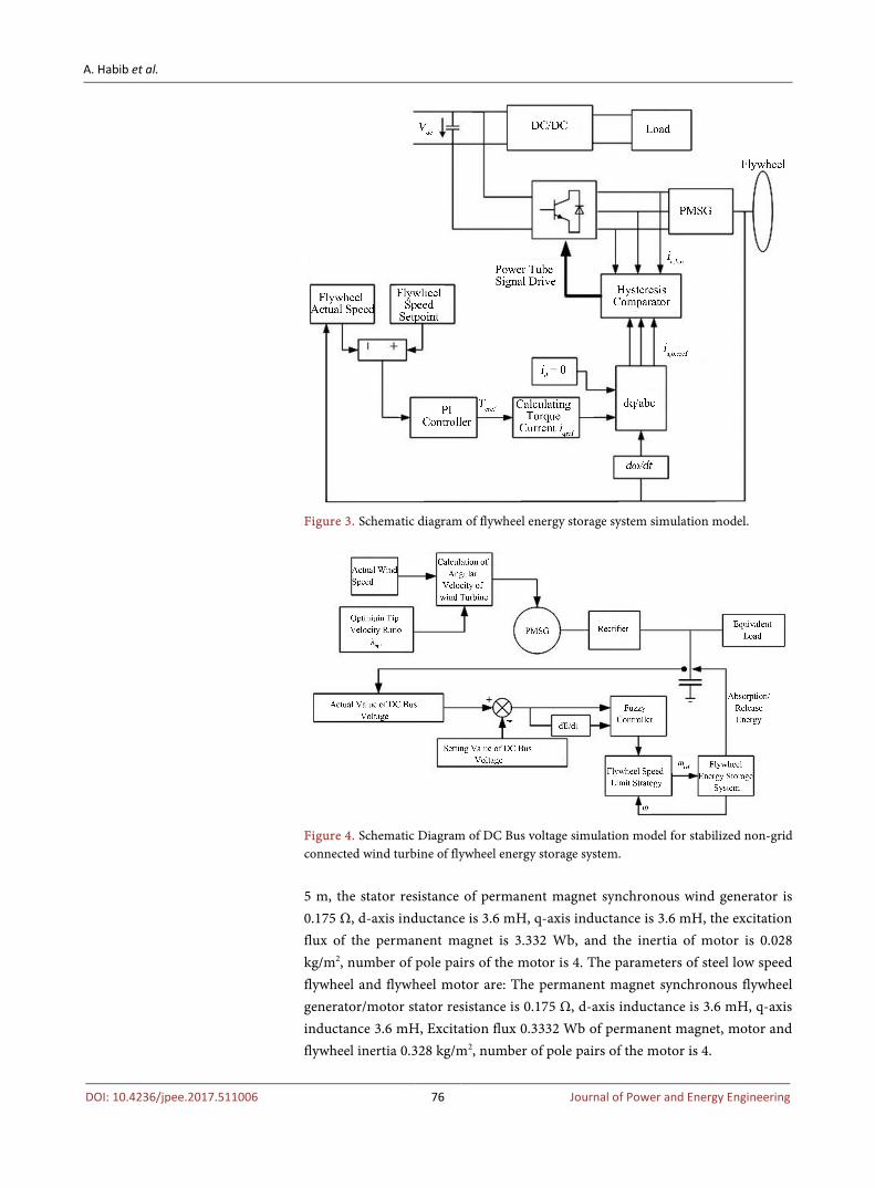
Flywheel energy storage system includes flywheel motor, power electronic con-verter and so on, which is the same as wind turbine. The flywheel motor also adopts the permanent magnet synchronous motor model provided by MATLAB Simulink; the power electronic converter uses the Universal Bridge module. Ac-cording to the control strategy shown in Figure 2, the speed control of the flyw-heel motor is carried out by the speed loop and the current hysteresis controller to realize the charging and discharging of the flywheel energy storage system, and Figure 3 is the structural diagram of the simulation model.
6.2. Simulation Model
A complete schematic diagram of the system simulation model can be obtained with the combination of wind turbine model and flywheel energy storage system model, as well as with the proposed fuzzy controller and control strategy of flywheel energy storage system for DC bus voltage of stabilized wind power gen-eration system. This diagram is shown in Figure 4.
7. Simulation Verification 7.1. System Parameters
The parameters of the wind turbine are: The sweep radius of the wind turbine is
A. Habib et al.
DOI: 10.4236/jpee.2017.511006 76 Journal of Power and Energy Engineering
Figure 3. Schematic diagram of flywheel energy storage system simulation model.
Figure 4. Schematic Diagram of DC Bus voltage simulation model for stabilized non-grid connected wind turbine of flywheel energy storage system. 5 m, the stator resistance of permanent magnet synchronous wind generator is 0.175 Ω, d-axis inductance is 3.6 mH, q-axis inductance is 3.6 mH, the excitation flux of the permanent magnet is 3.332 Wb, and the inertia of motor is 0.028 kg/m2, number of pole pairs of the motor is 4. The parameters of steel low speed flywheel and flywheel motor are: The permanent magnet synchronous flywheel generator/motor stator resistance is 0.175 Ω, d-axis inductance is 3.6 mH, q-axis inductance 3.6 mH, Excitation flux 0.3332 Wb of permanent magnet, motor and flywheel inertia 0.328 kg/m2, number of pole pairs of the motor is 4.

A. Habib et al.
DOI: 10.4236/jpee.2017.511006 77 Journal of Power and Energy Engineering
7.2. Simulation Results and Analysis
According to the given step curve of the simulated wind speed, a simulation model of the DC bus voltage of the non-grid connected wind turbine generator is built based on the fuzzy control of the flywheel energy storage system; and si-mulation results can be obtained. As shown in Figure 5, the simulated wind speed step curve is given, at 0.2 s, the wind speed jumps from 10 m/s to 8 m/s and back to 10 m/s at 0.23 s; at 0.5 s, the wind speed jumps from 10 m/s to 12 m/s and goes back to 10 m/s at 0.53 s. Figure 6 is the DC bus voltage waveform of the non-grid connected wind turbine when the flywheel energy storage system is not introduced. It can be seen that when the flywheel energy storage system is not introduced, the DC bus voltage fluctuates up and down with the wind speed jump, which seriously affects the power supply quality to the terminal load. Fig-ure 7 is the DC bus voltage waveform after the flywheel energy storage system is
Figure 5. Wind speed step simulation curve.
Figure 6. DC Bus voltage waveform without flywheel energy storage system.
A. Habib et al.
DOI: 10.4236/jpee.2017.511006 78 Journal of Power and Energy Engineering
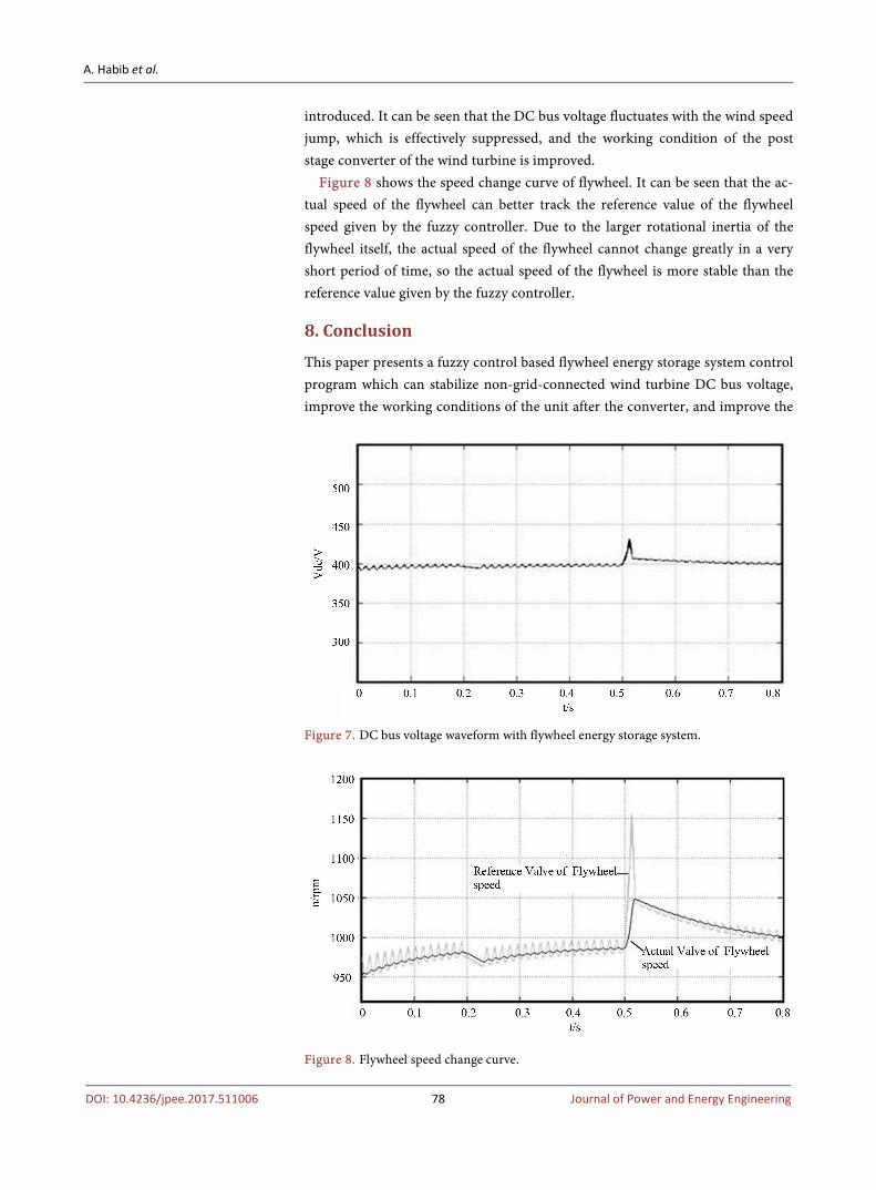
introduced. It can be seen that the DC bus voltage fluctuates with the wind speed jump, which is effectively suppressed, and the working condition of the post stage converter of the wind turbine is improved.
Figure 8 shows the speed change curve of flywheel. It can be seen that the ac-tual speed of the flywheel can better track the reference value of the flywheel speed given by the fuzzy controller. Due to the larger rotational inertia of the flywheel itself, the actual speed of the flywheel cannot change greatly in a very short period of time, so the actual speed of the flywheel is more stable than the reference value given by the fuzzy controller.
8. Conclusion
This paper presents a fuzzy control based flywheel energy storage system control program which can stabilize non-grid-connected wind turbine DC bus voltage, improve the working conditions of the unit after the converter, and improve the
Figure 7. DC bus voltage waveform with flywheel energy storage system.
Figure 8. Flywheel speed change curve.

A. Habib et al.
DOI: 10.4236/jpee.2017.511006 79 Journal of Power and Energy Engineering
quality of the power supply to the terminal load.
References [1] Lin, F. and Ma, Z.W. (2005) The Grid Connected Converter Control of Mul-
ti-Terminal DC System for Wind Farms. Eighth International Conference Electrical Machines and System, Nanjing.
[2] Xu, L. and Yao, L.Z. (2006) Power Electronics Options for Large Wind Farm Inte-gration: VSC-Based HVDC Transmission. Power Systems Conference and Exposi-tion, Atlanta.
[3] Meyer, C., et al. (2007) Control and Design of DC Grids for Offshore Wind Farms. IEEE Transactions on Industrial Applications, 43, 1475-1482. https://doi.org/10.1109/TIA.2007.908182
[4] Gu, W. (2006) New Strategy of China’s Wind Power Industry Development and Non-Grid Connection Theory of Wind Power. Chemical Industry Press, Beijing, 18-25. (In Chinese)