condensing units oa14, oa15
TRANSCRIPT

Condensing units OA14, OA15
07
.20
18 technical catalogue
2
ostrov.com
Customs Union directivesEU directivesEN ISO 9001:2009
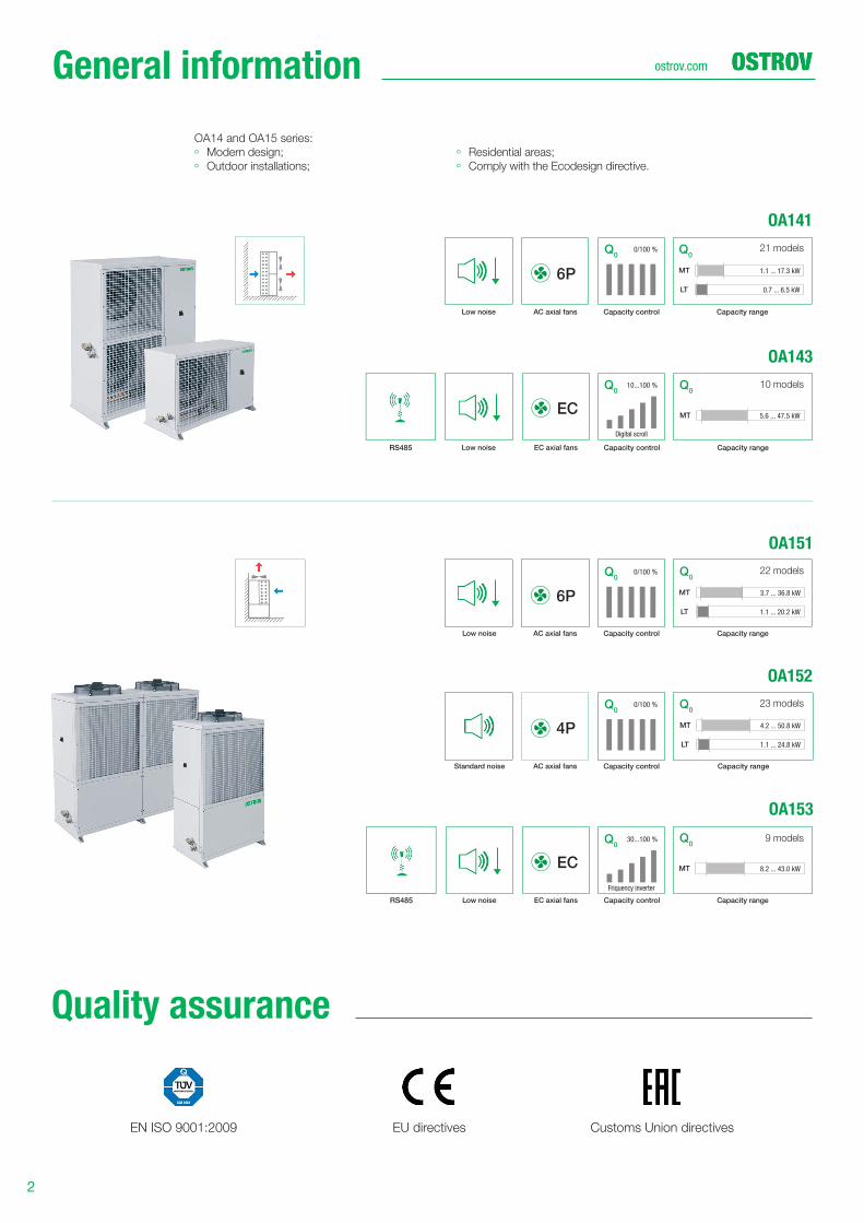
21 models
OA141
OA151
OA143
OA152
OA153
6P
6P
4P
EC
EC
Capacity range
MT
LT
1.1 ... 17.3 kW
0.7 ... 6.5 kW
Capacity range
Capacity range
MT
LT
Q0
3.7 ... 36.8 kW
1.1 ... 20.2 kW
Capacity range
MT
Q0
8.2 ... 43.0 kW
MT
LT
Q0
4.2 ... 50.8 kW
1.1 ... 24.8 kW
Capacity range
MT
Q0
5.6 ... 47.5 kW
RS485
RS485
Q0
Q0
Low noise
Low noise
Standard noise
Low noise
Low noise
EC axial fans
EC axial fans
AC axial fans
AC axial fans
AC axial fans
Capacity control
Capacity control
Digital scroll
Friquency inverter
Capacity control
Capacity control
Capacity control
0/100 %
0/100 %
0/100 %
10...100 %
30...100 %
Q0
Q0
Q0
Q0
10 models
22 models
23 models
9 models
ОА14 and OA15 series:
◦ Modern design;
◦ Outdoor installations;
◦ Residential areas;
◦ Comply with the Ecodesign directive.
General information
Quality assurance
3
ostrov.com
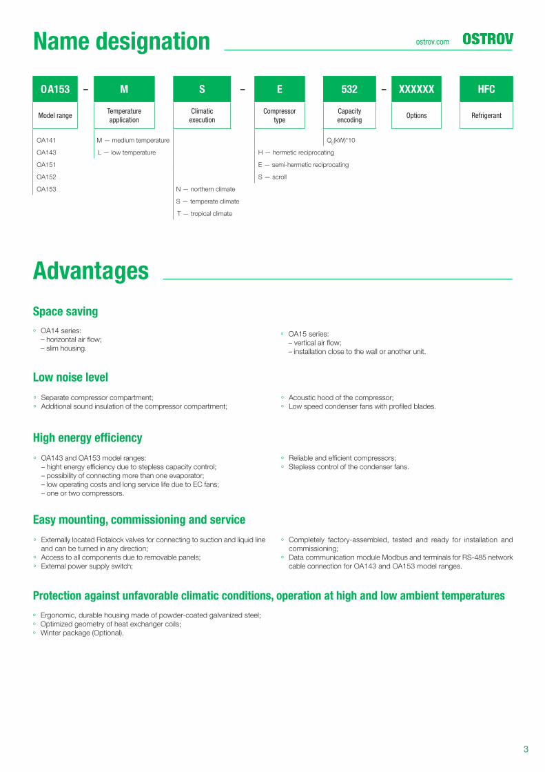
OА153 – M S – E 532 – XXXXXX HFC
Model rangeTemperature
application
Climatic
execution
Compressor
type
Capacity
encodingOptions Refrigerant
ОА141 M — medium temperature Q0(kW)*10
ОА143 L — low temperature H — hermetic reciprocating
ОА151 E — semi-hermetic reciprocating
ОА152 S — scroll
ОА153 N — northern climate
S — temperate climate
Т — tropical climate
Name designation
Space saving
Protection against unfavorable climatic conditions, operation at high and low ambient temperatures
Low noise level
High energy effi ciency
Easy mounting, commissioning and service
◦ OA143 and OA153 model ranges:
– hight energy effi ciency due to stepless capacity control;
– possibility of connecting more than one evaporator;
– low operating costs and long service life due to EC fans;
– one or two compressors.
◦ ОА14 series:
– horizontal air fl ow;
– slim housing.
◦ Reliable and effi cient compressors;
◦ Stepless control of the condenser fans.
◦ Externally located Rotalock valves for connecting to suction and liquid line
and can be turned in any direction;
◦ Access to all components due to removable panels;
◦ External power supply switch;
◦ Completely factory-assembled, tested and ready for installation and
commissioning;
◦ Data communication module Modbus and terminals for RS-485 network
cable connection for OA143 and OA153 model ranges.
◦ Ergonomic, durable housing made of powder-coated galvanized steel;
◦ Optimized geometry of heat exchanger coils;
◦ Winter package (Optional).
◦ Separate compressor compartment;
◦ Additional sound insulation of the compressor compartment;
◦ Acoustic hood of the compressor;
◦ Low speed condenser fans with profi led blades.
◦ ОА15 series:
– vertical air fl ow;
– installation close to the wall or another unit.
Advantages
4
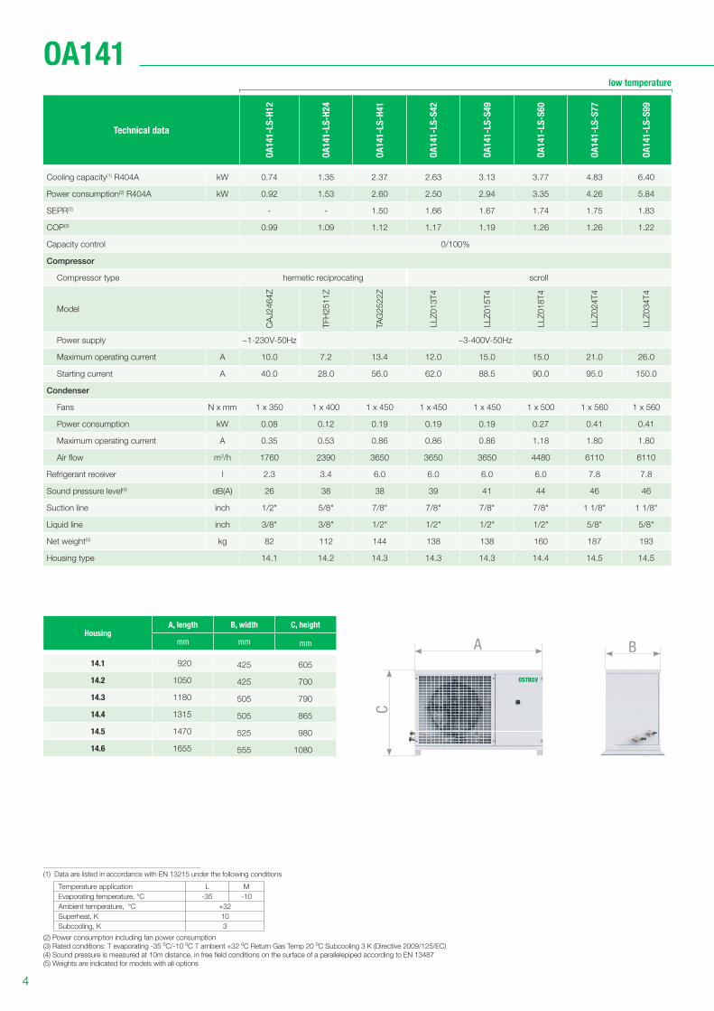
OA141
HousingА, length В, width С, height
mm mm mm
14.1 920 425 605
14.2 1050 425 700
14.3 1180 505 790
14.4 1315 505 865
14.5 1470 525 980
14.6 1655 555 1080
(1) Data are listed in accordance with EN 13215 under the following conditions
Temperature application L M
Evaporating temperature, °С -35 -10
Ambient temperature, °С +32
Superheat, K 10
Subcooling, K 3
(2) Power consumption including fan power consumption
(3) Rated conditions: Т evaporating -35 0С/-10 0С T ambient +32 0С Return Gas Temp 20 0С Subcooling 3 K (Directive 2009/125/EC)
(4) Sound pressure is measured at 10m distance, in free fi eld conditions on the surface of a parallelepiped according to EN 13487
(5) Weights are indicated for models with all options
low temperature
BA
C
Technical data
OA
14
1-L
S-H
12
OA
14
1-L
S-H
24
OA
14
1-L
S-H
41
OA
14
1-L
S-S
42
OA
14
1-L
S-S
49
OA
14
1-L
S-S
60
OA
14
1-L
S-S
77
OA
14
1-L
S-S
99
Cooling capacity(1) R404A kW 0.74 1.35 2.37 2.63 3.13 3.77 4.83 6.40
Power consumption(2) R404A kW 0.92 1.53 2.60 2.50 2.94 3.35 4.26 5.84
SEPR(3) - - 1.50 1.66 1.67 1.74 1.75 1.83
COP(3) 0.99 1.09 1.12 1.17 1.19 1.26 1.26 1.22
Capacity control 0/100%
Compressor
Compressor type hermetic reciprocating scroll
Model
CA
J2
46
4Z
TFH
25
11
Z
TAG
25
22
Z
LLZ
01
3T
4
LLZ
01
5T
4
LLZ
01
8T
4
LLZ
02
4T
4
LLZ
03
4T
4
Power supply ~1-230V-50Hz ~3-400V-50Hz
Maximum operating current А 10.0 7.2 13.4 12.0 15.0 15.0 21.0 26.0
Starting current А 40.0 28.0 56.0 62.0 88.5 90.0 95.0 150.0
Condenser
Fans N x mm 1 х 350 1 x 400 1 x 450 1 x 450 1 x 450 1 x 500 1 x 560 1 x 560
Power consumption kW 0.08 0.12 0.19 0.19 0.19 0.27 0.41 0.41
Maximum operating current А 0.35 0.53 0.86 0.86 0.86 1.18 1.80 1.80
Air fl ow m3/h 1760 2390 3650 3650 3650 4480 6110 6110
Refrigerant receiver l 2.3 3.4 6.0 6.0 6.0 6.0 7.8 7.8
Sound pressure level(4) dB(A) 26 38 38 39 41 44 46 46
Suction line inch 1/2" 5/8" 7/8" 7/8" 7/8" 7/8" 1 1/8" 1 1/8"
Liquid line inch 3/8" 3/8" 1/2" 1/2" 1/2" 1/2" 5/8" 5/8"
Net weight(5) kg 82 112 144 138 138 160 187 193
Housing type 14.1 14.2 14.3 14.3 14.3 14.4 14.5 14.5
5
ostrov.com
15 10
1
SP1
UZ1
4 9
11161718
2
SP3
7
Е1
М2
14
3 8
SP6
Е4
6
Е2
5
1212
М1
Е3 ST1
13
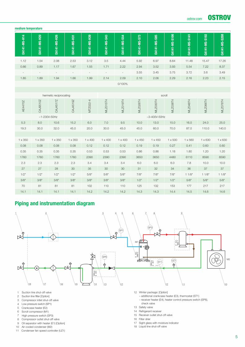
Winter package: [Option]
– additional crankcase heater (E3), thermostat (ST1)
– receiver heater (E4), heater control pressure switch (SP6),
check valve
Refrigerant receiver
Filter drier
Sight glass with moisture indicator
12
14
15
16
17
18
Safety valve13
Suction line filter [Option]
Oil separator with heater (E1) [Option]
Air cooled condenser (M2)
1
2
4
5
6
9
10
Condenser fan speed controller (UZ1)11
3
8
7
Crankcase heater (Е2)
Low pressure switch (SP1)
High pressure switch (SP3)
Scroll compressor (M1)
Compressor outlet shut-off valve
Receiver outlet shut-off valve
Compressor intlet shut-off valve
Suction line shut-off valve
medium temperature
Piping and instrumentation diagram
OA
14
1-M
S-H
14
OA
14
1-M
S-H
20
OA
14
1-M
S-H
26
OA
14
1-M
S-H
31
OA
14
1-M
S-H
39
OA
14
1-M
S-S
43
OA
14
1-M
S-S
54
OA
14
1-M
S-S
73
OA
14
1-M
S-S
85
OA
14
1-M
S-S
10
6
OA
14
1-M
S-S
14
1
OA
14
1-M
S-S
19
2
OA
14
1-M
S-S
20
8
1.12 1.54 2.08 2.53 3.12 3.5 4.44 5.92 6.97 8.64 11.48 15.47 17.26
0.66 0.89 1.17 1.67 1.55 1.71 2.22 2.94 3.52 3.93 5.54 7.22 8.37
- - - - - - - 3.55 3.45 3.75 3.72 3.6 3.49
1.85 1.89 1.94 1.66 1.99 2.14 2.09 2.10 2.06 2.29 2.16 2.23 2.15
0/100%
hermetic reciprocating scroll
AE
44
70
Z
CA
J9
51
0Z
CA
J4
51
7Z
CA
J4
51
9Z
MT
Z0
22
-4
MLZ
01
5T
4
MLZ
01
9T
4
MLZ
02
6T
4
MLZ
03
0T
4
MLZ
03
8T
4
MLZ
04
8T
4
MLZ
06
6T
4
MLZ
07
6T
4
~1-230V-50Hz ~3-400V-50Hz
5.3 8.0 10.6 15.2 6.0 7.0 9.5 10.0 13.0 15.0 16.0 24.0 25.0
19.3 30.0 32.0 45.0 20.0 30.0 45.0 45.0 60.0 70.0 87.0 110.0 140.0
1 х 350 1 x 350 1 x 350 1 x 350 1 x 400 1 x 400 1 x 400 1 х 450 1 х 450 1 x 500 1 x 560 1 x 630 1 x 630
0.08 0.08 0.08 0.08 0.12 0.12 0.12 0.19 0.19 0.27 0.41 0.60 0.60
0.35 0.35 0.35 0.35 0.53 0.53 0.53 0.86 0.86 1.18 1.80 1.20 1.20
1760 1760 1760 1760 2390 2390 2390 3650 3650 4480 6110 8590 8590
2.3 2.3 2.3 2.3 3.4 3.4 3.4 6.0 6.0 6.0 7.8 10.0 10.0
27 27 28 30 35 30 30 31 32 34 36 37 37
1/2" 1/2" 1/2" 1/2" 5/8" 5/8" 5/8" 7/8" 7/8" 7/8" 1 1/8" 1 1/8" 1 1/8"
3/8" 3/8" 3/8" 3/8" 3/8" 3/8" 3/8" 1/2" 1/2" 1/2" 5/8" 5/8" 5/8"
70 81 81 81 102 110 110 125 132 153 177 217 217
14.1 14.1 14.1 14.1 14.2 14.2 14.2 14.3 14.3 14.4 14.5 14.6 14.6

6
OA143
HousingА, length В, width С, height
mm mm mm
14.4 1315 505 865
14.6 1655 555 1080
HousingА, length В, width С, height
mm mm mm
14.7 1310 600 1645
14.9 1650 700 2055
BA
CC
A B
Technical data
OA
14
3-M
S-S
70
OA
14
3-M
S-S
92
OA
14
3-M
S-S
11
1
OA
14
3-M
S-S
13
0
OA
14
3-M
S-S
17
2
OA
14
3-M
S-S
22
0
OA
14
3-M
S-S
25
9
OA
14
3-M
S-S
31
5
OA
14
3-M
S-S
44
2
OA
14
3-M
S-S
58
2
Cooling capacity(1) R404A kW 5.61 7.44 9.04 10.55 13.93 18.36 21.10 25.93 36.81 47.47
Power consumption(2) R404A kW 2.45 3.22 4.06 4.85 6.10 9.04 9.70 12.64 18.04 28.58
SEPR(3) 4.03 4.14 3.81 3.73 3.91 3.75 3.73 3.63 3.76 3.32
COP(3) 2.39 2.42 2.33 2.28 2.39 2.13 2.28 2.16 2.14 1.74
Capacity control 10…100% Digital ScrollTM 5…100% Digital ScrollTM
Compressor
Compressor type scroll
Model
ZB
D2
1K
CE
ZB
D2
9K
CE
ZB
D3
8K
CE
ZB
D4
5K
CE
ZB
D5
7K
CE
ZB
D7
6K
5E
ZB
D4
5K
CE
-
ZB
45
KC
E
ZB
D5
7K
CE
-
ZB
57
KC
E
ZB
D7
6K
5E
-
ZB
76
K5
E
ZB
D1
14
K5
E+
ZB
11
4K
5E
Power supply ~3-400V-50Hz
Maximum operating current А 6.7 7.9 11.3 12.3 15.9 20.4 25.4 31.8 44.4 66.8
Starting current А 40.0 48.0 65.5 74.0 102.0 118.0 87.1 117.9 138.4 207.5
Condenser
Fans N x mm 1 x 500 1 x 500 1 x 500 1 x 500 1 x 630 1 x 630 2 x 500 2 x 500 2 x 630 2 x 630
Power consumption kW 0.5 0.5 0.5 0.5 0.7 0.7 1 1 1.4 1.4
Maximum operating current А 2.2 2.2 2.2 2.2 1.1 1.1 4.4 4.4 2.2 2.2
Air fl ow m3/h 6380 6380 6380 6380 9790 9790 12700 12700 19600 19600
Refrigerant receiver l 6.0 6.0 6.0 6.0 10.0 10.0 18.0 18.0 24.5 24.5
Sound pressure level(4) dB(A) 40 40 42 40 45 45 43 46 47 49
Suction line inch 7/8" 7/8" 7/8" 7/8" 1 1/8" 1 1/8" 1 3/8" 1 3/8" 1 5/8" 1 5/8"
Liquid line inch 1/2" 1/2" 1/2" 1/2" 5/8" 5/8" 7/8" 7/8" 7/8" 7/8"
Net weight(5) kg 144 144 154 156 221 243 339 343 505 520
Housing type 14.4 14.4 14.4 14.4 14.6 14.6 14.7 14.7 14.9 14.9
medium temperature
(1) Data are listed in accordance with EN 13215 under the following conditions
Temperature application M
Evaporating temperature, °С -10
Ambient temperature, °С +32
Superheat, K 10
Subcooling, K 3
(2) Power consumption including fan power consumption
(3) Rated conditions: Т evaporating -10 0С T ambient +32 0С Return Gas Temp 20 0С Subcooling 3 K (Directive 2009/125/EC)
(4) Sound pressure is measured at 10m distance, in free fi eld conditions on the surface of a parallelepiped according to EN 13487
(5) Weights are indicated for models with all options
7
ostrov.com
SP11
SP12BP1
BP2
Е1
М2SP6
Е4
Е2
Е3 ST1
1
1918
532 9 1814 15
25 24 23 22
10
21 18
12114
20
Е5 ST2
М1
ControllerController
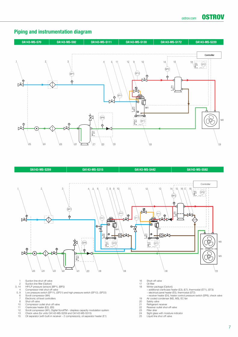
1 Suction line shut-off valve
2 Suction line filter [Option]
3, 14 HP/LP pressure sensors (BP1), (BP2)
4 Compressor inlet shut-off valve
5, 9 Low pressure switch (SP11), (SP21) and high pressure switch (SP12), (SP22)
6 Scroll compressor (M4)
7 Electronic oil level controllers
8 Shut-off valve
10 Compressor outlet shut-off valve
11 Crankcase heater (E2), (E6)
12 Scroll compressor (M1), Digital ScrollTM – stepless capacity modulation system
13 Check valve (for units OA143-MS-S259 and OA143-MS-S315)
15 Oil separator (with built-in receiver – 2 compressors), oil separator heater (E1)
16 Shutt-off valve
17 Oil filter
18 Winter package [Option]:
– additional crankcase heater (E3), (E7), thermostat (ST1), (ST3)
– electrical panel heater (E5), thermostat (ST2)
– receiver heater (E4), heater control pressure switch (SP6), check valve
19 Air cooled condenser (M2, M3), EC fan
20 Safety valve
21 Refrigerant receiver
22 Reseiver outlet shut-off valve
23 Filter drier
24 Sight glass with moisture indicator
25 Liquid line shut-off valve
OA143-MS-S70 OA143-MS-S92 OA143-MS-S111 OA143-MS-S130 OA143-MS-S172 OA143-MS-S220
OA143-MS-S259 OA143-MS-S315 OA143-MS-S442 OA143-MS-S582
Piping and instrumentation diagram
BP1
BP2
SP6 ST1ST3
ST2
SP22
SP21 SP11
SP12
1 32
2
13 14
24 23 22 21 20
64 10 117 8 9 125
5
15 16
19
1817
Controller
181818
8
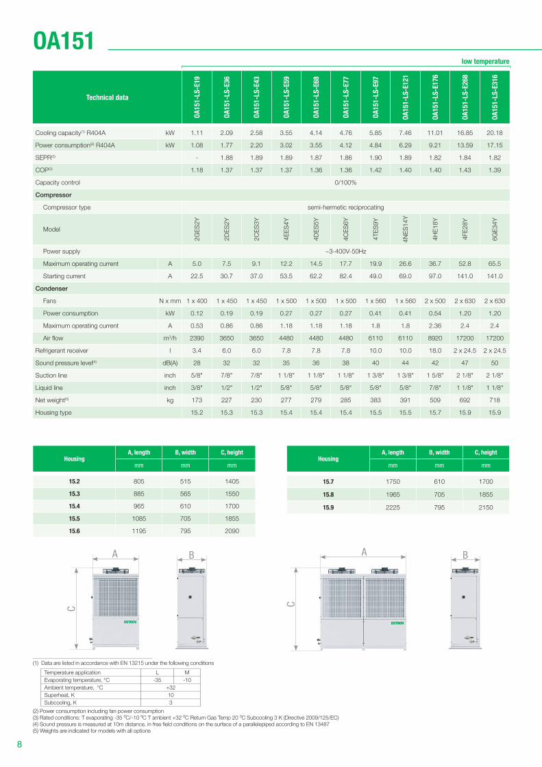
OA151
HousingА, length В, width С, height
mm mm mm
15.7 1750 610 1700
15.8 1965 705 1855
15.9 2225 795 2150
HousingА, length В, width С, height
mm mm mm
15.2 805 515 1405
15.3 885 565 1550
15.4 965 610 1700
15.5 1085 705 1855
15.6 1195 795 2090
low temperature
Technical data
OA
15
1-L
S-E
19
OA
15
1-L
S-E
36
OA
15
1-L
S-E
43
OA
15
1-L
S-E
59
OA
15
1-L
S-E
68
OA
15
1-L
S-E
77
OA
15
1-L
S-E
97
OA
15
1-L
S-E
12
1
OA
15
1-L
S-E
17
6
OA
15
1-L
S-E
26
8
OA
15
1-L
S-E
31
6
Cooling capacity(1) R404A kW 1.11 2.09 2.58 3.55 4.14 4.76 5.85 7.46 11.01 16.85 20.18
Power consumption(2) R404A kW 1.08 1.77 2.20 3.02 3.55 4.12 4.84 6.29 9.21 13.59 17.15
SEPR(3) - 1.88 1.89 1.89 1.87 1.86 1.90 1.89 1.82 1.84 1.82
COP(3) 1.18 1.37 1.37 1.37 1.36 1.36 1.42 1.40 1.40 1.43 1.39
Capacity control 0/100%
Compressor
Compressor type semi-hermetic reciprocating
Model
2G
ES
2Y
2D
ES
2Y
2C
ES
3Y
4E
ES
4Y
4D
ES
5Y
4C
ES
6Y
4T
ES
9Y
4N
ES
14
Y
4H
E1
8Y
4FE
28
Y
6G
E3
4Y
Power supply ~3-400V-50Hz
Maximum operating current А 5.0 7.5 9.1 12.2 14.5 17.7 19.9 26.6 36.7 52.8 65.5
Starting current А 22.5 30.7 37.0 53.5 62.2 82.4 49.0 69.0 97.0 141.0 141.0
Condenser
Fans N x mm 1 х 400 1 х 450 1 x 450 1 x 500 1 x 500 1 x 500 1 x 560 1 х 560 2 x 500 2 x 630 2 x 630
Power consumption kW 0.12 0.19 0.19 0.27 0.27 0.27 0.41 0.41 0.54 1.20 1.20
Maximum operating current А 0.53 0.86 0.86 1.18 1.18 1.18 1.8 1.8 2.36 2.4 2.4
Air fl ow m3/h 2390 3650 3650 4480 4480 4480 6110 6110 8920 17200 17200
Refrigerant receiver l 3.4 6.0 6.0 7.8 7.8 7.8 10.0 10.0 18.0 2 x 24.5 2 x 24.5
Sound pressure level(4) dB(A) 28 32 32 35 36 38 40 44 42 47 50
Suction line inch 5/8" 7/8" 7/8" 1 1/8" 1 1/8" 1 1/8" 1 3/8" 1 3/8" 1 5/8" 2 1/8" 2 1/8"
Liquid line inch 3/8" 1/2" 1/2" 5/8" 5/8" 5/8" 5/8" 5/8" 7/8" 1 1/8" 1 1/8"
Net weight(5) kg 173 227 230 277 279 285 383 391 509 692 718
Housing type 15.2 15.3 15.3 15.4 15.4 15.4 15.5 15.5 15.7 15.9 15.9
A A
C C
B B
(1) Data are listed in accordance with EN 13215 under the following conditions
Temperature application L M
Evaporating temperature, °С -35 -10
Ambient temperature, °С +32
Superheat, K 10
Subcooling, K 3
(2) Power consumption including fan power consumption
(3) Rated conditions: Т evaporating -35 0С/-10 0С T ambient +32 0С Return Gas Temp 20 0С Subcooling 3 K (Directive 2009/125/EC)
(4) Sound pressure is measured at 10m distance, in free fi eld conditions on the surface of a parallelepiped according to EN 13487
(5) Weights are indicated for models with all options
9
ostrov.com
32
SP3
UZ1
Е1М1
Е3
ST1
SP6
Е4
Е2
16
125
1515 14
4
17
1110
192021
SP1
6
18
1
13
М2
М3
89
7
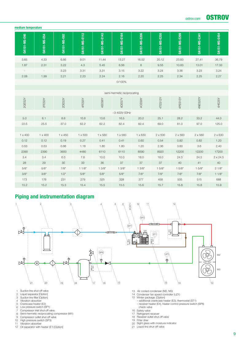
Suction line filter [Option]
Low pressure swi
Suction line shut-off valve
Compressor inlet shut-off valve
Compressor outlet shut-off valve Receiver outlet shut-off valve
tch (SP1)
Vibration absorberCrankcase heater (Е2)
Semi-hermetic reciprocating compressor (M1)
Oil separator with heater (E1) [Option]
Air cooled condenser (M2, M3)
Condenser fan speed controller (UZ1)Winter package: [Option]– additional crankcase heater (E3), thermostat (ST1)
– receiver heater (E4), heater control pressure switch (SP6)
check valve
Safety valveRefrigerant receiver
Filter drierSight glass with moisture indicator
High pressure switch (SP3)
Vibration absorber
13
14 15
16
17
1819
20
21
1
2
3
45
6
9
12
7
11
10
8
Liquid separator [Option]
medium temperature
Piping and instrumentation diagram
OA
15
1-M
S-E
46
OA
15
1-M
S-E
54
OA
15
1-M
S-E
82
OA
15
1-M
S-E
11
2
OA
15
1-M
S-E
14
3
OA
15
1-M
S-E
16
4
OA
15
1-M
S-E
20
6
OA
15
1-M
S-E
25
0
OA
15
1-M
S-E
29
9
OA
15
1-M
S-E
34
1
OA
15
1-M
S-E
45
4
3.65 4.33 6.66 9.01 11.44 13.27 16.52 20.12 23.83 27.41 36.79
1.87 2.31 3.22 4.3 5.45 6.56 8 9.55 10.83 13.01 17.33
- - 3.23 3.31 3.31 3.15 3.22 3.24 3.36 3.23 3.24
2.08 1.99 2.21 2.23 2.24 2.16 2.20 2.25 2.34 2.25 2.27
0/100%
semi-hermetic reciprocating
2G
ES
2Y
2FE
S3
Y
2D
ES
3Y
4FE
S5
Y
4E
ES
6Y
4D
ES
7Y
4C
ES
9Y
4T
ES
12
Y
4P
ES
15
Y
4N
ES
20
Y
4H
E2
5Y
~3-400V-50Hz
5.0 6.1 8.6 10.8 13.6 16.5 20.2 25.1 28.2 33.2 44.0
22.5 25.5 37.0 62.2 62.2 82.4 82.4 69.0 81.0 97.0 125.0
1 х 400 1 х 400 1 x 450 1 x 500 1 x 560 1 x 560 1 x 630 2 х 500 2 x 560 2 x 560 2 x 630
0.12 0.12 0.19 0.27 0.41 0.41 0.60 0.54 0.82 0.82 1.20
0.53 0.53 0.86 1.18 1.80 1.80 1.20 2.36 3.60 3.6 2.40
2390 2390 3650 4480 6110 6110 8590 8920 12200 12200 17200
3.4 3.4 6.0 7.8 10.0 10.0 18.0 18.0 24.5 24.5 2 x 24.5
28 29 30 33 36 37 37 37 40 41 40
5/8" 5/8" 7/8" 1 1/8" 1 3/8" 1 3/8" 1 3/8" 1 5/8" 1 5/8" 1 5/8" 2 1/8"
3/8" 3/8" 1/2" 5/8" 5/8" 5/8" 7/8" 7/8" 7/8" 7/8" 1 1/8"
173 176 231 279 325 328 377 458 505 515 688
15.2 15.2 15.3 15.4 15.5 15.5 15.6 15.7 15.8 15.8 15.9

10
OA152
HousingА, length В, width С, height
mm mm mm
15.7 1750 610 1700
15.9 2225 795 2150
HousingА, length В, width С, height
mm mm mm
15.2 805 515 1405
15.3 885 565 1550
15.4 965 610 1700
15.5 1085 705 1855
15.6 1195 795 2090
low temperature
Technical data
OA
15
2-L
S-H
20
OA
15
2-L
S-H
28
OA
15
2-L
S-H
38
OA
15
2-L
S-H
54
OA
15
2-L
S-H
82
OA
15
2-L
S-H
10
5
OA
15
2-L
S-E
12
8
OA
15
2-L
S-E
19
0
OA
15
2-L
S-E
24
6
OA
15
2-L
S-E
34
1
OA
15
2-L
S-E
39
4
Cooling capacity(1) R404A kW 1.06 1.56 2.09 3.13 4.81 6.35 7.78 11.64 15.86 21.30 24.76
Power consumption(2) R404A kW 1.05 1.55 2.14 3.28 4.84 6.3 6.85 10 13.8 19.74 23.18
SEPR(3) - - 1.44 1.53 1.52 1.53 1.80 1.82 1.71 1.64 1.58
COP(3) 1.13 1.12 1.09 1.07 1.11 1.13 1.34 1.36 1.34 1.26 1.24
Capacity control 0/100%
Compressor
Compressor type hermetic reciprocating semi-hermetic reciprocating
Model
NT
Z0
48
-4
NT
Z0
68
-4
NT
Z0
96
-4
NT
Z1
36
-4
NT
Z2
15
-4
NT
Z2
71
-4
4N
ES
14
Y
4H
E1
8Y
4FE
28
Y
6G
E3
4Y
6FE
44
Y
Power supply ~3-400V-50Hz
Maximum operating current А 4.8 8.4 10.1 14.3 22.3 27.0 26.6 36.7 52.8 65.5 83.2
Starting current А 16.0 25.0 32.0 51.0 74.0 96.0 69.0 97.0 141.0 141.0 219.0
Condenser
Fans N x mm 1 х 400 1 х 400 1 x 450 1 x 450 1 x 500 1 x 500 1 x 560 2 х 500 2 x 500 2 x 630 2 x 630
Power consumption kW 0.16 0.16 0.38 0.38 0.68 0.68 0.83 1.36 1.36 3.94 3.94
Maximum operating current А 0.73 0.73 1.80 1.80 3 3 3.60 6 6 6.80 6.80
Air fl ow m3/h 3340 3340 5450 5450 6660 6660 7950 13300 13300 27400 27400
Refrigerant receiver l 3.4 3.4 6.0 6.0 7.8 7.8 10.0 18.0 18.0 2 x 24.5 2 x 24.5
Sound pressure level(4) dB(A) 43 41 52 47 53 53 52 50 55 58 59
Suction line inch 5/8" 5/8" 7/8" 7/8" 1 1/8" 1 1/8" 1 3/8" 1 5/8" 1 5/8" 2 1/8" 2 1/8"
Liquid line inch 3/8" 3/8" 1/2" 1/2" 5/8" 5/8" 5/8" 7/8" 7/8" 1 1/8" 1 1/8"
Net weight(5) kg 137 138 194 194 252 254 399 514 542 742 755
Housing type 15.2 15.2 15.3 15.3 15.4 15.4 15.5 15.7 15.7 15.9 15.9
A A
C C
B B
(1) Data are listed in accordance with EN 13215 under the following conditions
Temperature application L M
Evaporating temperature, °С -35 -10
Ambient temperature, °С +32
Superheat, K 10
Subcooling, K 3
(2) Power consumption including fan power consumption
(3) Rated conditions: Т evaporating -35 0С/-10 0С T ambient +32 0С Return Gas Temp 20 0С Subcooling 3 K (Directive 2009/125/EC)
(4) Sound pressure is measured at 10m distance, in free fi eld conditions on the surface of a parallelepiped according to EN 13487
(5) Weights are indicated for models with all options
11
ostrov.com
16 11
1
SP1
SP3
UZ1
5 8 10
12171819 14
Е3
Е1
М1
М2
15
97
ST1
SP6
Е4
4
Е2
6
1313
2 3
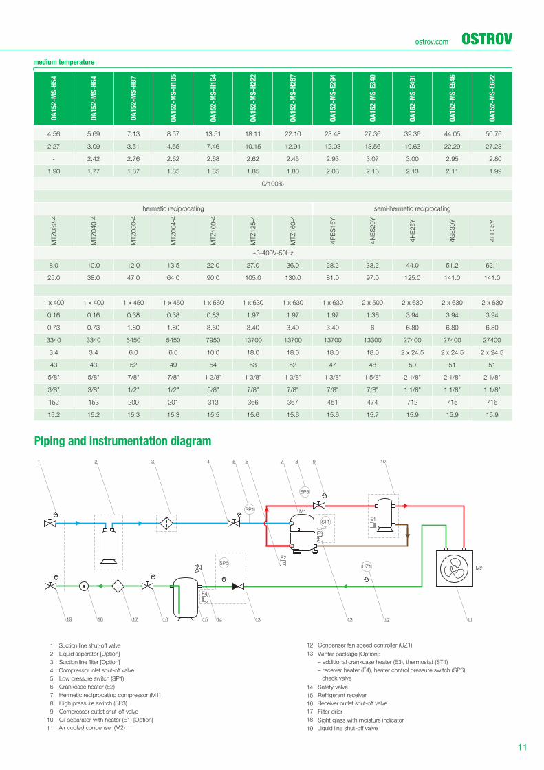
Suction line filter [Option]
Oil separator with heater (E1) [Option]
Air cooled condenser (M2)
1
2
4
5
6
9
10
Condenser fan speed controller (UZ1)
Refrigerant receiver
Filter drier
Sight glass with moisture indicator
11
12
13
15
16
17
18
19
3
8
7
Crankcase heater (Е2)
Low pressure switch (SP1)
High pressure switch (SP3)
Hermetic reciprocating compressor (M1)
Safety valve14
Winter package [Option]:
– additional crankcase heater (E3), thermostat (ST1)
– receiver heater (E4), heater control pressure switch (SP6),
check valve
Liquid separator [Option]
Compressor inlet shut-off valve
Compressor outlet shut-off valve
Receiver outlet shut-off valve
Suction line shut-off valve
medium temperature
Piping and instrumentation diagram
OA
15
2-M
S-H
54
OA
15
2-M
S-H
64
OA
15
2-M
S-H
87
OA
15
2-M
S-H
10
5
OA
15
2-M
S-H
16
4
OA
15
2-M
S-H
22
2
OA
15
2-M
S-H
26
7
OA
15
2-M
S-E
29
4
OA
15
2-M
S-E
34
0
OA
15
2-M
S-E
49
1
OA
15
2-M
S-E
54
6
OA
15
2-M
S-E
62
2
4.56 5.69 7.13 8.57 13.51 18.11 22.10 23.48 27.36 39.36 44.05 50.76
2.27 3.09 3.51 4.55 7.46 10.15 12.91 12.03 13.56 19.63 22.29 27.23
- 2.42 2.76 2.62 2.68 2.62 2.45 2.93 3.07 3.00 2.95 2.80
1.90 1.77 1.87 1.85 1.85 1.85 1.80 2.08 2.16 2.13 2.11 1.99
0/100%
hermetic reciprocating semi-hermetic reciprocating
MTZ
032-4
MTZ
040-4
MTZ
050-4
MTZ
064-4
MTZ
100-4
MTZ
125-4
MTZ
160-4
4P
ES
15
Y
4N
ES
20
Y
4H
E2
5Y
4G
E3
0Y
4FE
35
Y
~3-400V-50Hz
8.0 10.0 12.0 13.5 22.0 27.0 36.0 28.2 33.2 44.0 51.2 62.1
25.0 38.0 47.0 64.0 90.0 105.0 130.0 81.0 97.0 125.0 141.0 141.0
1 х 400 1 х 400 1 x 450 1 x 450 1 x 560 1 x 630 1 x 630 1 х 630 2 x 500 2 x 630 2 x 630 2 x 630
0.16 0.16 0.38 0.38 0.83 1.97 1.97 1.97 1.36 3.94 3.94 3.94
0.73 0.73 1.80 1.80 3.60 3.40 3.40 3.40 6 6.80 6.80 6.80
3340 3340 5450 5450 7950 13700 13700 13700 13300 27400 27400 27400
3.4 3.4 6.0 6.0 10.0 18.0 18.0 18.0 18.0 2 x 24.5 2 x 24.5 2 x 24.5
43 43 52 49 54 53 52 47 48 50 51 51
5/8" 5/8" 7/8" 7/8" 1 3/8" 1 3/8" 1 3/8" 1 3/8" 1 5/8" 2 1/8" 2 1/8" 2 1/8"
3/8" 3/8" 1/2" 1/2" 5/8" 7/8" 7/8" 7/8" 7/8" 1 1/8" 1 1/8" 1 1/8"
152 153 200 201 313 366 367 451 474 712 715 716
15.2 15.2 15.3 15.3 15.5 15.6 15.6 15.6 15.7 15.9 15.9 15.9
12
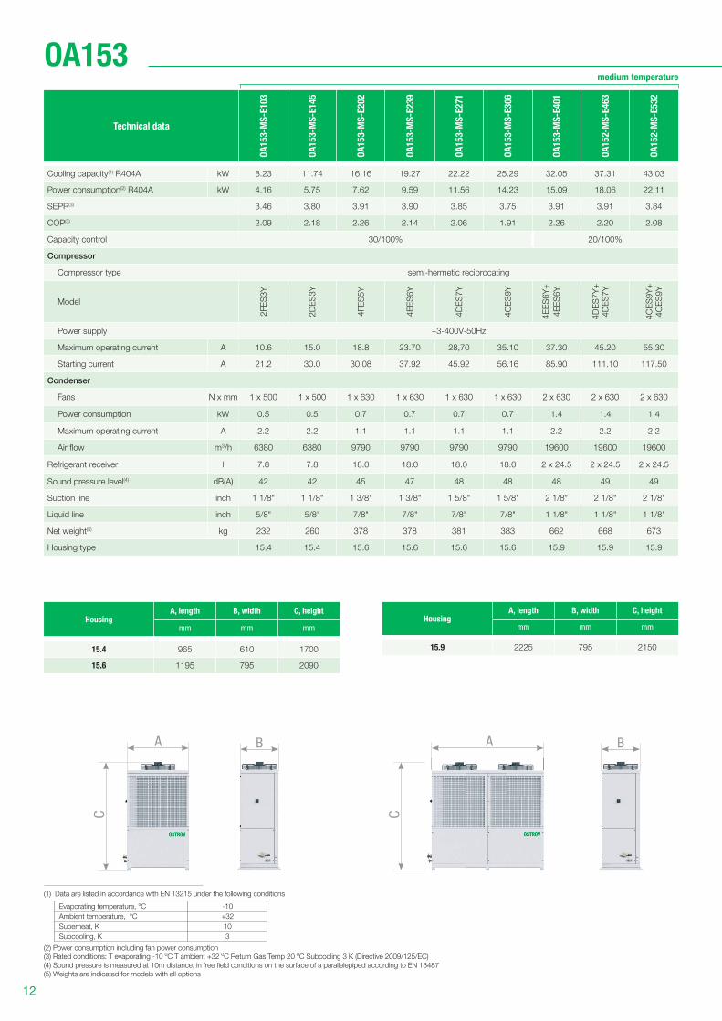
OA153
HousingА, length В, width С, height
mm mm mm
15.4 965 610 1700
15.6 1195 795 2090
Technical data
OA
15
3-M
S-E
10
3
OA
15
3-M
S-E
14
5
OA
15
3-M
S-E
20
2
OA
15
3-M
S-E
23
9
OA
15
3-M
S-E
27
1
OA
15
3-M
S-E
30
6
OA
15
3-M
S-E
40
1
OA
15
2-M
S-E
46
3
OA
15
2-M
S-E
53
2
Cooling capacity(1) R404A kW 8.23 11.74 16.16 19.27 22.22 25.29 32.05 37.31 43.03
Power consumption(2) R404A kW 4.16 5.75 7.62 9.59 11.56 14.23 15.09 18.06 22.11
SEPR(3) 3.46 3.80 3.91 3.90 3.85 3.75 3.91 3.91 3.84
COP(3) 2.09 2.18 2.26 2.14 2.06 1.91 2.26 2.20 2.08
Capacity control 30/100% 20/100%
Compressor
Compressor type semi-hermetic reciprocating
Model
2FE
S3
Y
2D
ES
3Y
4FE
S5
Y
4E
ES
6Y
4D
ES
7Y
4C
ES
9Y
4E
ES
6Y
+
4E
ES
6Y
4D
ES
7Y
+4
DE
S7
Y
4C
ES
9Y
+4
CE
S9
Y
Power supply ~3-400V-50Hz
Maximum operating current А 10.6 15.0 18.8 23.70 28,70 35.10 37.30 45.20 55.30
Starting current А 21.2 30.0 30.08 37.92 45.92 56.16 85.90 111.10 117.50
Condenser
Fans N x mm 1 х 500 1 x 500 1 x 630 1 x 630 1 x 630 1 x 630 2 x 630 2 x 630 2 x 630
Power consumption kW 0.5 0.5 0.7 0.7 0.7 0.7 1.4 1.4 1.4
Maximum operating current А 2.2 2.2 1.1 1.1 1.1 1.1 2.2 2.2 2.2
Air fl ow m3/h 6380 6380 9790 9790 9790 9790 19600 19600 19600
Refrigerant receiver l 7.8 7.8 18.0 18.0 18.0 18.0 2 x 24.5 2 x 24.5 2 x 24.5
Sound pressure level(4) dB(A) 42 42 45 47 48 48 48 49 49
Suction line inch 1 1/8" 1 1/8" 1 3/8" 1 3/8" 1 5/8" 1 5/8" 2 1/8" 2 1/8" 2 1/8"
Liquid line inch 5/8" 5/8" 7/8" 7/8" 7/8" 7/8" 1 1/8" 1 1/8" 1 1/8"
Net weight(5) kg 232 260 378 378 381 383 662 668 673
Housing type 15.4 15.4 15.6 15.6 15.6 15.6 15.9 15.9 15.9
(1) Data are listed in accordance with EN 13215 under the following conditions
Evaporating temperature, °С -10
Ambient temperature, °С +32
Superheat, K 10
Subcooling, K 3
(2) Power consumption including fan power consumption
(3) Rated conditions: Т evaporating -10 0С T ambient +32 0С Return Gas Temp 20 0С Subcooling 3 K (Directive 2009/125/EC)
(4) Sound pressure is measured at 10m distance, in free fi eld conditions on the surface of a parallelepiped according to EN 13487
(5) Weights are indicated for models with all options
medium temperature
HousingА, length В, width С, height
mm mm mm
15.9 2225 795 2150
A A
C C
B B
13
ostrov.com
SP11 SP21SP12
BP1
BP2
SP6
SP22
ST2
ST1 ST3
1 432 13 14
24 23 22 21 20
6 10789
5 15 16 17
19 18
11 12
1717
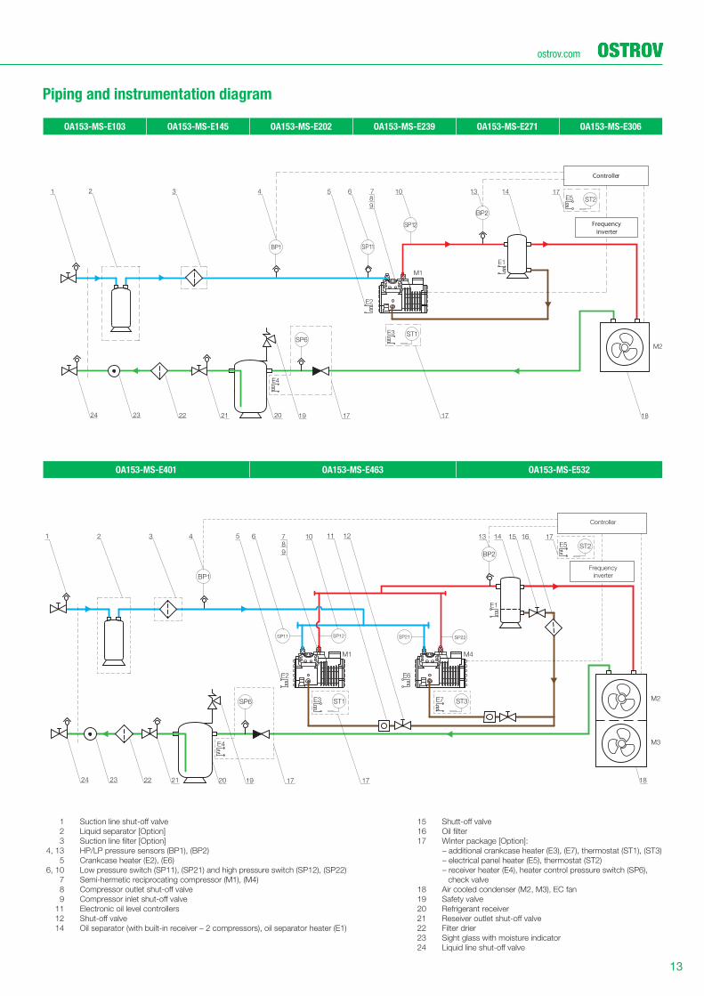
OA153-MS-E103 OA153-MS-E145 OA153-MS-E202 OA153-MS-E239 OA153-MS-E271 OA153-MS-E306
OA153-MS-E401 OA153-MS-E463 OA153-MS-E532
Piping and instrumentation diagram
BP2
SP12
SP6ST1
ST2
1717
1
18
6432 10 13 14
24 23 22 21 20
5
19
789
17
Frequency
inverter
Controller
Controller
Frequency
inverter
BP1 SP11
1 Suction line shut-off valve
2 Liquid separator [Option]
3 Suction line filter [Option]
4, 13 HP/LP pressure sensors (BP1), (BP2)
5 Crankcase heater (E2), (E6)
6, 10 Low pressure switch (SP11), (SP21) and high pressure switch (SP12), (SP22)
7 Semi-hermetic reciprocating compressor (M1), (M4)
8 Compressor outlet shut-off valve
9 Compressor inlet shut-off valve
11 Electronic oil level controllers
12 Shut-off valve
14 Oil separator (with built-in receiver – 2 compressors), oil separator heater (E1)
15 Shutt-off valve
16 Oil filter
17 Winter package [Option]:
– additional crankcase heater (E3), (E7), thermostat (ST1), (ST3)
– electrical panel heater (E5), thermostat (ST2)
– receiver heater (E4), heater control pressure switch (SP6),
check valve
18 Air cooled condenser (M2, M3), EC fan
19 Safety valve
20 Refrigerant receiver
21 Reseiver outlet shut-off valve
22 Filter drier
23 Sight glass with moisture indicator
24 Liquid line shut-off valve
14
ostrov.com
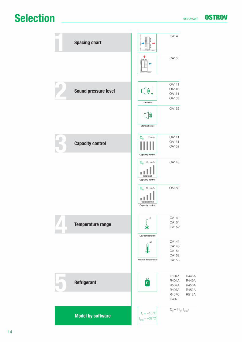
Spacing chart
Sound pressure level
Capacity control
Temperature range
Refrigerant
R134a R448A
R404A R449A
R507A R450A
R407A R452A
R407С R513A
R407F
t0 = –10°С
tamb
= +32°С
Q0 = f (t
0, t
amb)
OA141
OA151
OA152
OA141
OA151
OA152
Selection
1
2
3
4
5
OA141
OA143
OA151
OA153
OA14
Model by software
OA143
OA153
OA141
OA143
OA151
OA152
OA153
OA152
OA15
Low noise
Standart noise
Low temperature
Medium temperature
Q0
Capacity control
Friquency inverter
Capacity control
0/100 %
30...100 %
Q0
Q0
Capacity control
Digital scroll
10...100 %
LT
MT
ostrov.comLinks
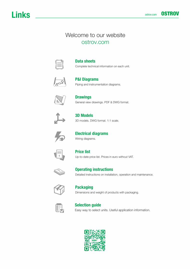
P&I DiagramsPiping and instrumentation diagrams.
Data sheetsComplete technical information on each unit.
DrawingsGeneral view drawings. PDF & DWG format.
3D Models3D models. DWG format. 1:1 scale.
Electrical diagramsWiring diagrams.
Price listUp-to-date price list. Prices in euro without VAT.
Operating instructionsDetailed instructions on installation, operation and maintenance.
PackagingDimensions and weight of products with packaging.
Welcome to our website
ostrov.com
OSTROV
Selection guide Easy way to select units. Useful application information.

Russia & CIS
6, 2nd Bakuninsky Alleyway, Mytishchi,
Moscow Region, 141011, Russia
tel.: +7 495 582 44 44
fax: +7 495 582 44 45
European Union
Ringhoff erova 115/1, 15521
Prague 5, Czech Republic
tel.: +420 234 252 223
fax: +420 234 252 225
ostrov.com
Sub
ject
to t
echnic
al a
mend
ments
without
prior
notice