concept of hvac_ by palash chandra das
TRANSCRIPT

PALASH CHANDRA DAS (www.uscgmp.com) 1
What is HVAC ?
Heating, Ventilation, and Air Conditioning
5/2/2015
By Palash Chandra Dashttp://www.uscgmp.com
PALASH CHANDRA DAS (www.uscgmp.com) 2
Introduction
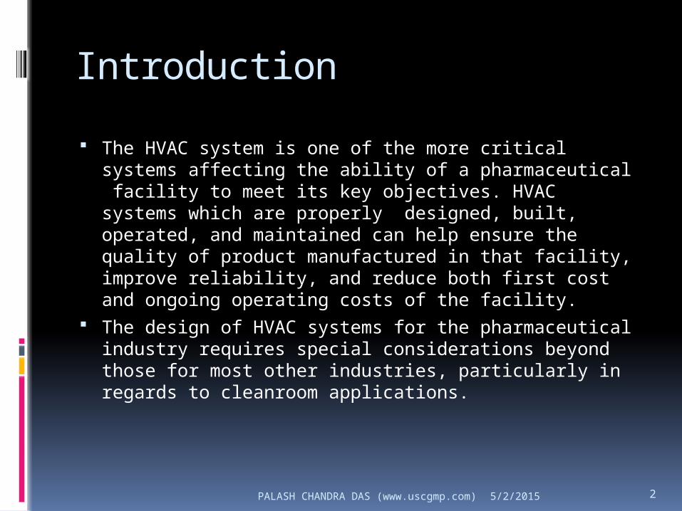
The HVAC system is one of the more critical systems affecting the ability of a pharmaceutical facility to meet its key objectives. HVAC systems which are properly designed, built, operated, and maintained can help ensure the quality of product manufactured in that facility, improve reliability, and reduce both first cost and ongoing operating costs of the facility.
The design of HVAC systems for the pharmaceutical industry requires special considerations beyond those for most other industries, particularly in regards to cleanroom applications.
5/2/2015

PALASH CHANDRA DAS (www.uscgmp.com) 3
How the concept came?
Most people live in homes with equipment incorporated into the building to keep them comfortable. They have windows to allow natural ventilation and heating and cooling s
We have the same goal in our pharmaceutical manufacturing workplace – to make people comfortable, but we also have the more exacting requirement to control the impact of the environment on the finished product. systems to maintain desired temperatures.
5/2/2015

PALASH CHANDRA DAS (www.uscgmp.com) 4
Why is the requirement?
Air temperature at the critical location may affect product or product contact surfaces
Relative humidity of the air at the critical location may affect product moisture content, or may affect product contact surfaces (via corrosion, etc.)
Airborne contamination at the critical location (may affect product purity or product contact surfaces)“Some variables, such as local contaminants, depend on other HVAC variables such as room pressure, air changes, airflow volume, airflow direction and velocity, and air filter efficiency”
5/2/2015

PALASH CHANDRA DAS (www.uscgmp.com) 5
Background of design:
Operational feature How to Design? Major component? How it is works? Automation with BMS/EMS
5/2/2015
PALASH CHANDRA DAS (www.uscgmp.com) 6
Operational feature
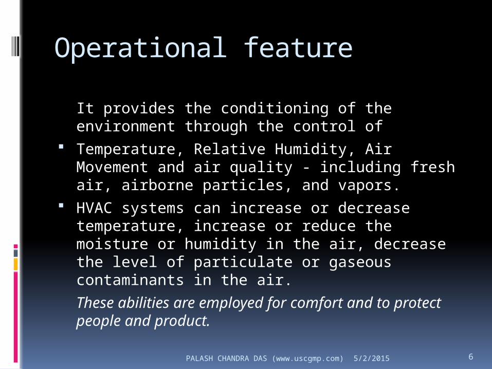
It provides the conditioning of the environment through the control of
Temperature, Relative Humidity, Air Movement and air quality - including fresh air, airborne particles, and vapors.
HVAC systems can increase or decrease temperature, increase or reduce the moisture or humidity in the air, decrease the level of particulate or gaseous contaminants in the air.
These abilities are employed for comfort and to protect people and product.
5/2/2015

PALASH CHANDRA DAS (www.uscgmp.com) 7
How to Design?
Once through Recirculating systems Exhaust (Extract) system
5/2/2015

PALASH CHANDRA DAS (www.uscgmp.com) 8
Once through
5/2/2015

PALASH CHANDRA DAS (www.uscgmp.com) 9
Recirculating systems
5/2/2015

PALASH CHANDRA DAS (www.uscgmp.com) 10
Exhaust (Extract) system
5/2/2015

PALASH CHANDRA DAS (www.uscgmp.com) 11
How many AHU’s should be used? Use of multiple units improves reliability of the area –
it would be unusual for all of the units to fail. The use of multiple smaller units might make air
balancing easier The use of multiple smaller units means that the
main distribution ducts are smaller, making then easier to route in small ceiling voids.
It is easier to make modifications to parts of the facility in future and upgrade a small unit than change a large single unit
Use of multiple units allows for easier separation of areas within a multi-product concurrent manufacturing plant.
5/2/2015

PALASH CHANDRA DAS (www.uscgmp.com) 12
Major components
5/2/2015
PALASH CHANDRA DAS (www.uscgmp.com) 13
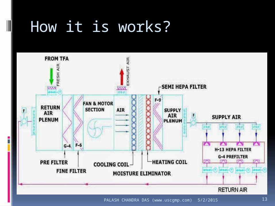
How it is works?
5/2/2015
PALASH CHANDRA DAS (www.uscgmp.com) 14
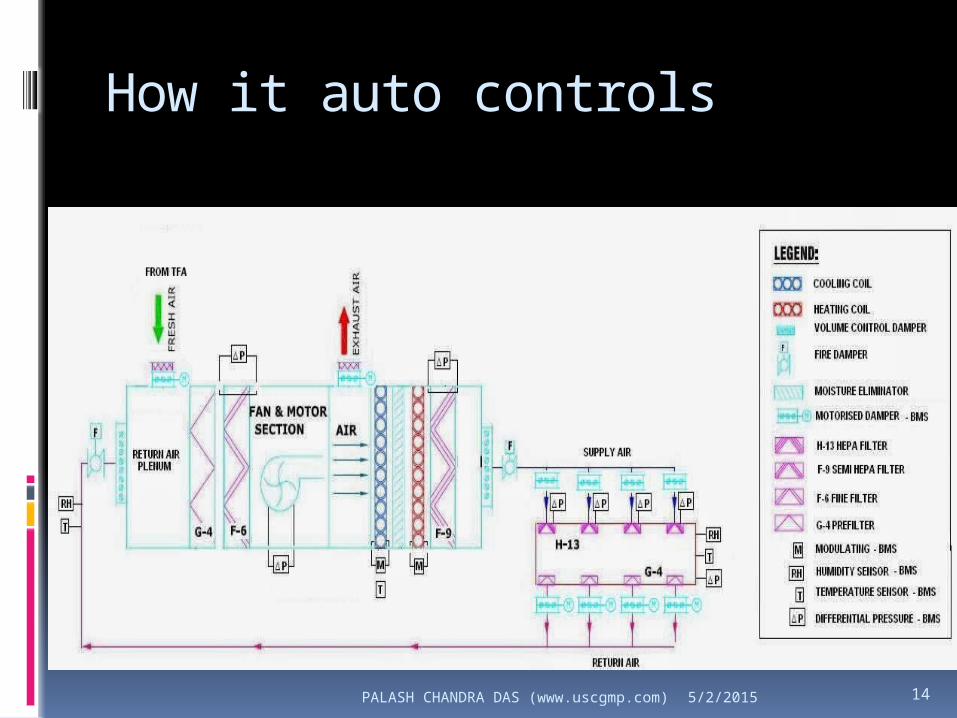
How it auto controls
5/2/2015

PALASH CHANDRA DAS (www.uscgmp.com) 15
Key feature of BMS
Monitor, control and display the room parameter of
HVAC system like temperature, relative humidity
and room pressure as applicable
Operation of AHU’s
Time scheduling of AHU’s.
Preventive maintenance scheduling.
Differential pressure monitoring across filters ( F-6,
F-9 and H-13)
Alarm and audit log features
5/2/2015
PALASH CHANDRA DAS (www.uscgmp.com) 16
Qualification:
Concept of Design aspect: From URS to DQ Concept of Qualification BMS integration and CVS? Operational aspects
Operation Maintenance
5/2/2015

PALASH CHANDRA DAS (www.uscgmp.com) 17
Concept of Design aspect
For HVAC systems in a pharmaceutical environment, user requirements are developed as a result of gathering relevant data with regards to the following:
Process – Critical environmental parameters that must be achieved and maintained.
Quality – Regulatory guidance and quality principles to guide decision making on HVAC parameters that can have product impact.
Operations – Proper environment for the working conditions that impact the HVAC design.
Maintenance – Provide input on critical aspects of the HVAC design that would ensure a low TCO
5/2/2015

PALASH CHANDRA DAS (www.uscgmp.com) 18
Based on requirement
5/2/2015
PALASH CHANDRA DAS (www.uscgmp.com) 19
CQA/CQP
Typical HVAC performance parameters that impact CQA/CQP are: HEPA filter test data Air change rates/airflow volumes Area differential pressures Temperature Relative humidity Particle count
Typical HVAC-related room performance parameters which impact CQA/CQP are:
Clean up & Room recovery time Total particle count (area classification) Microbial Viable particulate test results – in air Microbial Viable particulate test results – swab tests
5/2/2015
PALASH CHANDRA DAS (www.uscgmp.com) 20
Critical Quality Attributes/Parameters (CQA/CQP)
How to monitored. Some examples may be: Humidity is monitored by an independent SCADA
based environmental monitoring system. Temperature is monitored by an independent SCADA
based environmental monitoring system. Air quality is monitored by a routine test using a
particle counter to per ISO CEN 14644 for all particles., and microbial
Microbial monitoring for viable particles is tested per local SOP.
Room pressure differentials are monitored by an independent SCADA based environmental monitoring system
5/2/2015

PALASH CHANDRA DAS (www.uscgmp.com) 21
Critical Quality Attributes/Parameters (CQA/CQP)
Define how the are achieved, and any associated equipment risks of failure and the probability of detection of those failures. Some examples may be:
Humidity control is achieved by either dehumidifying the air through cooling below its dew point to remove moisture, or by adding moisture with a steam humidifier. As humidity is continuously monitored by a verified system it is considered adequate to commission the humidifier/dehumidifier system, and maintain it under engineering change control
Temperature control is obtained through the use of the heating or cooling coils. As temperature is continuously monitored by a verified system it is considered adequate to commission the heat system, and maintain it under engineering change control.
Air quality is obtained through the final HEPA grade filter which is leak tested annually, with a particle count conducted periodically. As the HEPA filter integrity is not continuously monitored, and is directly responsible for this aspect of the system performance it will be verified and maintained under quality change control.
Room pressure differentials are achieved through the leakage from and to the conditioned space from adjacent areas and via the HVAC system balance. As pressure is continuously monitored by a verified system it is considered adequate to commission the duct/damper system and maintain it under engineering change control.
5/2/2015

PALASH CHANDRA DAS (www.uscgmp.com) 225/2/2015

PALASH CHANDRA DAS (www.uscgmp.com) 23
Concept of Qualification
5/2/2015
PALASH CHANDRA DAS (www.uscgmp.com) 24
Concept of Qualification
QUALIFICATION APPROACH Following tests are to be carried out as a part of area qualification
of HVAC system: Installed HEPA filter integrity Air velocity and air changes per hour calculation Air flow pattern visualization study using visible smoke Room Differential Pressure monitoring Room Temperature and Relative Humidity Monitoring Air Borne particle count (non-viable) Active and passive Microbial Monitoring (By settle plate/Air
sampling Method) Recovery Study
For all grade A equipments, HEPA filter integrity testing and air velocity are carried out during operational qualification Moreover, room Differential Pressure monitoring and recovery study is not applicable for Grade A units.
5/2/2015

PALASH CHANDRA DAS (www.uscgmp.com) 25
Concept of Qualification
Air velocity and air changes per hour calculation:
Average air velocity (FPM) =
A + B + C + D + E (FPM)
5
For unidirectional airflow units (LAF units, Biosafety cabinets and dynamic pass boxes) down flow and exhaust HEPA filter air velocity shall be 0.45 meters/second (90 FPM ± 20%). However, higher velocities may be appropriate in operations generating high levels of particulates.
5/2/2015

PALASH CHANDRA DAS (www.uscgmp.com) 26
Concept of Qualification
Air Changes per hour: To determine air changes of the cleanrooms, calculate the
supply air volume for each final HEPA filter as follows:
Qs = Vs x As
Where, Qs is the supply airflow volume from each final filter (CFM)
Vs is the average supply airflow velocity at each final HEPA filter (FPM)
As is the area of filter grill (sq. ft.) Take sum of airflow volume from all the supply air filters
installed for a single cleanroom or enclosure. This will lead to a total airflow volume (Vt) for the cleanroom.
From the volume of the room, find out air changes per hour using the formula:ACPH =
Total airflow volume (CFM) x 60
Volume of the room (cu.ft.) 5/2/2015

PALASH CHANDRA DAS (www.uscgmp.com) 27
Concept of Qualification
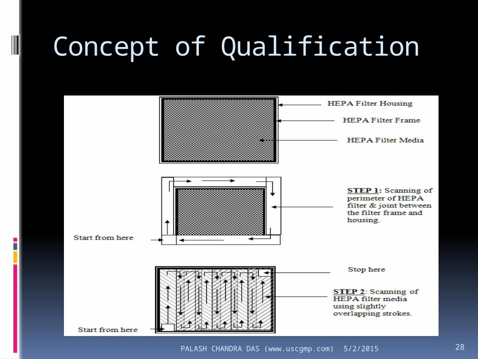
HEPA filter integrity test: Aim:
This test is performed to confirm that the HEPA filters are properly installed and leaks have not developed during installation/use. The test verifies the absence of leakage, relevant to the cleanliness performance of the installation.
The test will detect small holes and other damages in the filter medium and the frame sealant as well as bypass air in the filter frame, in its gasket, in the grid system and other fixtures.
Before filter integrity testing, ensure that the air flow velocity of the HEPA filter is carried out and complies as per test requirements.
5/2/2015
PALASH CHANDRA DAS (www.uscgmp.com) 28
Concept of Qualification
5/2/2015

PALASH CHANDRA DAS (www.uscgmp.com) 29
Concept of Qualification
Room Differential Pressure monitoring: Aim:
The purpose of this test is to verify the capability of the HVAC system to maintain the specified pressure difference between the rooms and associated environments.
Sampling frequency: Carry out monitoring of differential pressure
thrice in a shift during environment monitoring i.e, 3 consecutive days in at rest condition followed by 7 consecutive working days in at operation condition.
5/2/2015

PALASH CHANDRA DAS (www.uscgmp.com) 30
Concept of Qualification
Room Temperature and Relative Humidity Monitoring:
Aim: The purpose of this test is to demonstrate the
capability of the HVAC system to maintain the air temperature and humidity level within the control limits and over the time period.
Sampling frequency: Carry out monitoring of temperature and relative
humidity thrice in a shift during environment monitoring for 3 consecutive days in at rest condition followed by 7 consecutive working days in at operation condition.
5/2/2015

PALASH CHANDRA DAS (www.uscgmp.com) 31
Concept of Qualification
Air flow pattern visualization/airflow direction study:
Aim: The purpose of flow visualization is to confirm spatial
and temporal characteristics of airflow in the clean rooms, grade A equipments and controlled environments. Appropriate procedure for flow visualization should be performed to demonstrate that the maintenance of cleanliness is effective.
The airflow pattern should be carried out in both at rest and at operation conditions to assess the behavior of the air flow with man and material interventions.
5/2/2015
PALASH CHANDRA DAS (www.uscgmp.com) 32
Concept of Qualification
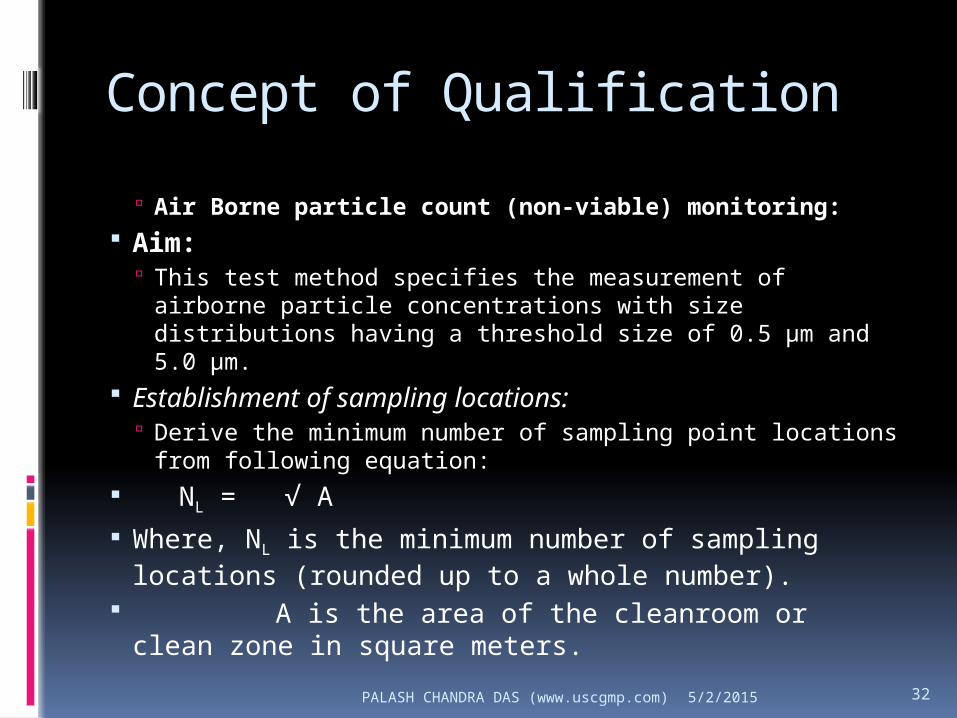
Air Borne particle count (non-viable) monitoring: Aim:
This test method specifies the measurement of airborne particle concentrations with size distributions having a threshold size of 0.5 μm and 5.0 μm.
Establishment of sampling locations: Derive the minimum number of sampling point locations
from following equation:
NL = √ A
Where, NL is the minimum number of sampling locations (rounded up to a whole number).
A is the area of the cleanroom or clean zone in square meters.
5/2/2015

PALASH CHANDRA DAS (www.uscgmp.com) 33
Concept of Qualification
Establishment of single sample volume per location: As per ISO-14644-1, sampling volume is calculated as below:
Where, Vs is the minimum sample volume per location (in liters)
C n,m is the class limit (in number of particles per cubic meter) for the largest considered particle size specified for the relevant grade,
20 is the defined number of particles that could be counted if the particle concentration is at the class limit. To calculate the class level at multiple particle sizes, select a
sample volume for the largest size, this is also the largest required volume. This will ensure the sample data is valid for all sizes.
Vs =20
x 1000C n,m
5/2/2015

PALASH CHANDRA DAS (www.uscgmp.com) 34
Concept of QualificationISO 4.8 = (20 / 20 ) x 1000 = 1000 liter
ISO 5 = (20 / 29 ) x 1000 = 690 liter
ISO 6 = (20 / 293 ) x 1000 = 69 liter
ISO 7 = (20 / 2930 ) x 1000 = 6.9 liter
ISO 8 = (20 / 29300 ) x 1000 = 0.69 liter
CLASS
Minimum sampling volume (Ltrs.)
Minimum sampling time
(for particle counter with 50 LPM flow
rate)
Minimum sampling time
(for particle counter with 100 LPM flow
rate)
ISO 4.8 1000 20 minutes 10 minutes
ISO 5 1000 20 minutes 10 minutes
ISO 6 69 02 minute 01 minute
ISO 7 6.9 01 minute 01 minute
ISO 8 2.0 01 minute 01 minute
5/2/2015

PALASH CHANDRA DAS (www.uscgmp.com) 35
Concept of Qualification
Sampling frequency: As a part of initial qualification,
monitoring of the clean rooms for non-viable particle count shall be done for at least 3 consecutive working days in at rest condition, followed by 7 consecutive working days in at operation condition, covering all the sampling points each day.
5/2/2015

PALASH CHANDRA DAS (www.uscgmp.com) 36
Concept of Qualification
Microbial Monitoring: Aim:
To ascertain that the HVAC system under consideration is capable of providing and maintaining the required level of the microbiological quality in the rooms supplied by it.
For active sampling, 1000 Ltrs of air should be sampled from each location. For passive air sampling, plates should be exposed for not less than 4 hours.
5/2/2015

PALASH CHANDRA DAS (www.uscgmp.com) 37
Concept of Qualification
Incubate all exposed plates in inverted position at 32.5 ± 2.5º C temperature for minimum of 48 hours duration.
Now transfer the plates to incubator with temperature of 22.5 ± 2.5º C and continue incubation for minimum of next 72 hours duration.
Also correlate the obtained CFUs at the end of 5-day incubation period with the standard correction table applicable to respective air sampler and enter the corrected CFUs in the report.
Sampling frequency: As a part of initial qualification, monitoring of the clean
rooms for viable monitoring shall be done for at least 3 consecutive working days in at rest condition, followed by 7 consecutive working days in at operation condition, covering all the sampling points each day.
5/2/2015
PALASH CHANDRA DAS (www.uscgmp.com) 38
Concept of Qualification
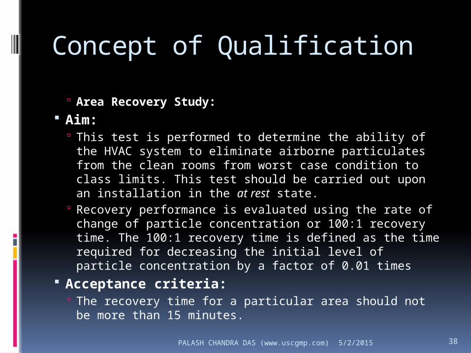
Area Recovery Study: Aim:
This test is performed to determine the ability of the HVAC system to eliminate airborne particulates from the clean rooms from worst case condition to class limits. This test should be carried out upon an installation in the at rest state.
Recovery performance is evaluated using the rate of change of particle concentration or 100:1 recovery time. The 100:1 recovery time is defined as the time required for decreasing the initial level of particle concentration by a factor of 0.01 times
Acceptance criteria: The recovery time for a particular area should not be
more than 15 minutes.5/2/2015

PALASH CHANDRA DAS (www.uscgmp.com) 39
BMS integration and CVS?
Supply air fan. Return air fan Chilled Water outlet Temp. Hot Water outlet Temp. Fresh air ON/OFF damper. Exhaust air ON/OFF damper 2-way modulating cooling valve. 3-way modulating heating valve. Mixing ON/OFF damper Fresh air connected through TFA ON/OFF damper Fine & Semi hepa Filter A temperature and RH sensor installed in common
return air duct. Room Temperature and Humidity
Sensors(Monitoring). Room differential pressure sensor’s. Differential pressure sensor across hepa filters. Differential pressure switch across hepa filters. Room motorized dampers. VFD’s trip status and software integration.
I/O verification Alarms and
interlocks Data
restrorization Software backup Audit trial Password
verification Real time clock
verification Screen shots
verifications
5/2/2015

PALASH CHANDRA DAS (www.uscgmp.com) 40
Operational aspects
Operation Maintenance
5/2/2015

PALASH CHANDRA DAS (www.uscgmp.com) 41
Operation
For the manufacture of sterile pharmaceutical preparations, four grades of clean areas are distinguished as follows:
Grade A: The local zone for high-risk operations, e.g. filling and making aseptic connections. Normally such conditions are achieved by using unidirectional airflow workstation. Unidirectional airflow systems should provide a homogeneous air speed of 0.36–0.54 m/s (guidance value) at a defined test position 15–30 cm below the terminal filter or air distributor system. The velocity at working level should not be less than 0.36 m/s. The uniformity and effectiveness of the unidirectional airflow should be demonstrated by undertaking airflow visualization tests.
Grade B: In aseptic preparation and filling, this is the background environment for the Grade A zone.
Grades C and D: Clean areas for carrying out less critical stages in the manufacture of sterile products or carrying out activities during which the product is not directly exposed (i.e. aseptic connection with aseptic connectors and operations in a closed system).
5/2/2015

PALASH CHANDRA DAS (www.uscgmp.com) 42
Design to Operation
5/2/2015

PALASH CHANDRA DAS (www.uscgmp.com) 435/2/2015

PALASH CHANDRA DAS (www.uscgmp.com) 445/2/2015
PALASH CHANDRA DAS (www.uscgmp.com) 45
Maintenance
There should be a planned preventive maintenance programme, procedures and records for the HVAC system. Records should be kept.
Operating and maintenance (O&M) manuals, schematic drawings, protocols and reports should be maintained as reference documents for any future changes and upgrades to the system. These documents should be kept up to date, containing any system revisions made.
Maintenance personnel should receive appropriate training. HEPA filters should be changed either by a specialist or a trained
person, and then followed by installed filter leakage testing. Any maintenance activity should be assessed critically to determine
any Maintenance activities should normally be scheduled to take place
outside production hours, and any system stoppage should be assessed with a view to the possible need for requalification of an area as a result of an interruption of the service. impact on product quality including possible contamination.
5/2/2015

PALASH CHANDRA DAS (www.uscgmp.com) 46
Regulatory requirements:
Regulatory aspects? Current updates
5/2/2015

PALASH CHANDRA DAS (www.uscgmp.com) 47
Schedule M
Appropriate action shall be taken immediately if the result of particulate
and microbiological monitoring indicates that the counts exceed the limits. The Standard
Operating Procedures shall contain corrective action. After major engineering
modification to the HVAC system of any area, all monitoring shall be re-performed
before production commences.5/2/2015
PALASH CHANDRA DAS (www.uscgmp.com) 48
USFDA
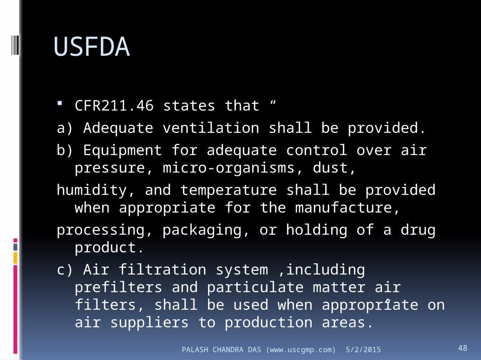
CFR211.46 states that “
a) Adequate ventilation shall be provided.
b) Equipment for adequate control over air pressure, micro-organisms, dust,
humidity, and temperature shall be provided when appropriate for the manufacture,
processing, packaging, or holding of a drug product.
c) Air filtration system ,including prefilters and particulate matter air filters, shall be used when appropriate on air suppliers to production areas.”
5/2/2015

PALASH CHANDRA DAS (www.uscgmp.com) 49
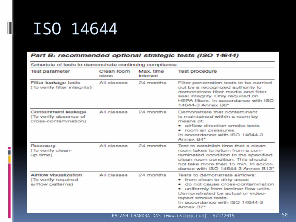
ISO 14644
5/2/2015
PALASH CHANDRA DAS (www.uscgmp.com) 50
ISO 14644
5/2/2015
PALASH CHANDRA DAS (www.uscgmp.com) 51
Annex 15: Qualification and Validation A risk assessment should be carried
out where there may be direct contact with the product, e.g. heating, ventilation and air-conditioning (HVAC) systems, or indirect contact such as through heat exchangers to mitigate any risks of failure
5/2/2015

PALASH CHANDRA DAS (www.uscgmp.com) 52
483
5/2/2015
PALASH CHANDRA DAS (www.uscgmp.com) 53
Reference
ASHRAE handbook 2000. HVAC Systems and Equipment. Atlanta, GA, ASHRAE, 2008. http://www.ashrae.org/technology/page/548.
ICH. Good Manufacturing Practice Guide for Active Pharmaceutical Ingredients.Q7A (March 15, 2000).
FDA. FDA’s proposed current good manufacturing practices (GMP) for regs. For large volume parenterals (LVP). Fed Reg (June 1, 1976). Preliminary Concept Paper of Sterile Drug Products Produced by Aseptic Processing, draft paper, Sept. 27, 2002.
Pharmaceutical Engineering Guide Vol. 4: Water and Steam Guide. Tampa, FL: ISPE, (1997).
Code of Federal Regulation Title 21, Part 211. Current good manufacturing practice for finished pharmaceuticals (2002).
General information <1116>: Microbiological evaluation of clean rooms and other controlled environments. U.S. Pharmacopeia. vol. 25. Rockville, MD: U.S. Pharmacopeial Convention, p. 2206–2212 (2002).
EU. GMP annex: Manufacturing of sterile products (1996).
Federal Standard 209E. Airborne Particulate Cleanliness Classes in Cleanroom and Clean Zone (Sept. 11, 1992).
Pharmaceutical Engineering Guide Vol. 3: Sterile Manufacturing Facilities.Tampa, FL: ISPE, (1997).
FDA/ISPE. Pharmaceutical Engineering Guide. vol. 1. Tampa, FL.
Classification of Airborne Particulates, in Cleanrooms and Associated Controlled Environments—Part 1, ISO 14644-1, Geneva: International Organization for Standardization (1999).
WHO GMP. Good Practices in Manufacturing of Pharmaceutical Products in WHO Expert Committee on Specifications for Pharmaceutical Preparations, 32 edition, Geneva (1992).
5/2/2015