concentrator plus/vacufuge® plus - eppendorf
TRANSCRIPT
uctionsplus/Vacufuge® plusEN)nstructions
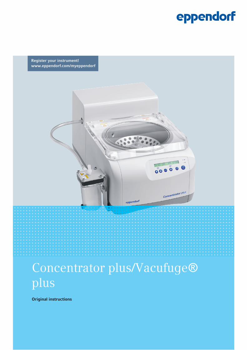
Register your instrument! www.eppendorf.com/myeppendorf
Concentrator plus/Vacufuge® plusOriginal instructions

Copyright ©2020 All rights reserved, including graphics and images. No part of this publication may be
reproduced without the prior permission of the copyright owner.
Eppendorf® and the Eppendorf Brand Design are registered trademarks of Eppendorf AG, Germany.
Registered trademarks and protected trademarks are not marked in all cases with ® or ™ in this manual.
U.S. Patents are listed on www.eppendorf.com/ip
5305 900.038-04/042020
3Table of contents
Concentrator plus/Vacufuge® plus
English (EN)
Table of contents
1 Operating instructions . . . . . . . . . . . . . . . . . . . . . . . . . . . . . . . . . . . . . . . . . . . . . . . . . . . . . . . . . . . . . . 71.1 Using this manual . . . . . . . . . . . . . . . . . . . . . . . . . . . . . . . . . . . . . . . . . . . . . . . . . . . . . . . . . . . . . 7
1.2 Danger symbols and danger levels . . . . . . . . . . . . . . . . . . . . . . . . . . . . . . . . . . . . . . . . . . . . . . . . 7
1.2.1 Danger symbols. . . . . . . . . . . . . . . . . . . . . . . . . . . . . . . . . . . . . . . . . . . . . . . . . . . . . . . . 7
1.2.2 Danger levels. . . . . . . . . . . . . . . . . . . . . . . . . . . . . . . . . . . . . . . . . . . . . . . . . . . . . . . . . . 7
1.3 Symbols used . . . . . . . . . . . . . . . . . . . . . . . . . . . . . . . . . . . . . . . . . . . . . . . . . . . . . . . . . . . . . . . . 8
1.4 Abbreviations used . . . . . . . . . . . . . . . . . . . . . . . . . . . . . . . . . . . . . . . . . . . . . . . . . . . . . . . . . . . . 8
2 Safety. . . . . . . . . . . . . . . . . . . . . . . . . . . . . . . . . . . . . . . . . . . . . . . . . . . . . . . . . . . . . . . . . . . . . . . . . . . . 92.1 Intended use . . . . . . . . . . . . . . . . . . . . . . . . . . . . . . . . . . . . . . . . . . . . . . . . . . . . . . . . . . . . . . . . . 9
2.2 User profile . . . . . . . . . . . . . . . . . . . . . . . . . . . . . . . . . . . . . . . . . . . . . . . . . . . . . . . . . . . . . . . . . . 9
2.3 Application limits . . . . . . . . . . . . . . . . . . . . . . . . . . . . . . . . . . . . . . . . . . . . . . . . . . . . . . . . . . . . . 9
2.3.1 Declaration concerning the ATEX directive (2014/34/EU) . . . . . . . . . . . . . . . . . . . . . . . 9
2.4 Information on product liability . . . . . . . . . . . . . . . . . . . . . . . . . . . . . . . . . . . . . . . . . . . . . . . . . . 9
2.5 Warnings for intended use . . . . . . . . . . . . . . . . . . . . . . . . . . . . . . . . . . . . . . . . . . . . . . . . . . . . . 10
2.5.1 Personal injury or damage to the device. . . . . . . . . . . . . . . . . . . . . . . . . . . . . . . . . . . . 10
2.5.2 Incorrect handling of the device . . . . . . . . . . . . . . . . . . . . . . . . . . . . . . . . . . . . . . . . . . 11
2.5.3 Incorrect handling of the rotors . . . . . . . . . . . . . . . . . . . . . . . . . . . . . . . . . . . . . . . . . . 12
2.5.4 Extreme strain on the sample tubes . . . . . . . . . . . . . . . . . . . . . . . . . . . . . . . . . . . . . . . 13
2.5.5 Vacuum . . . . . . . . . . . . . . . . . . . . . . . . . . . . . . . . . . . . . . . . . . . . . . . . . . . . . . . . . . . . . 13
2.6 Safety instructions on the device . . . . . . . . . . . . . . . . . . . . . . . . . . . . . . . . . . . . . . . . . . . . . . . . 14
3 Product description . . . . . . . . . . . . . . . . . . . . . . . . . . . . . . . . . . . . . . . . . . . . . . . . . . . . . . . . . . . . . . . 153.1 Product overview. . . . . . . . . . . . . . . . . . . . . . . . . . . . . . . . . . . . . . . . . . . . . . . . . . . . . . . . . . . . . 15
3.2 Delivery package. . . . . . . . . . . . . . . . . . . . . . . . . . . . . . . . . . . . . . . . . . . . . . . . . . . . . . . . . . . . . 17
3.3 Features. . . . . . . . . . . . . . . . . . . . . . . . . . . . . . . . . . . . . . . . . . . . . . . . . . . . . . . . . . . . . . . . . . . . 17
3.4 Name plate . . . . . . . . . . . . . . . . . . . . . . . . . . . . . . . . . . . . . . . . . . . . . . . . . . . . . . . . . . . . . . . . . 19
4 Installation . . . . . . . . . . . . . . . . . . . . . . . . . . . . . . . . . . . . . . . . . . . . . . . . . . . . . . . . . . . . . . . . . . . . . . 214.1 Selecting the location . . . . . . . . . . . . . . . . . . . . . . . . . . . . . . . . . . . . . . . . . . . . . . . . . . . . . . . . . 21
4.2 Preparing installation . . . . . . . . . . . . . . . . . . . . . . . . . . . . . . . . . . . . . . . . . . . . . . . . . . . . . . . . . 22
4.3 Installing the instrument . . . . . . . . . . . . . . . . . . . . . . . . . . . . . . . . . . . . . . . . . . . . . . . . . . . . . . . 24
4.3.1 General installation . . . . . . . . . . . . . . . . . . . . . . . . . . . . . . . . . . . . . . . . . . . . . . . . . . . . 24
4.3.2 Complete system: Connecting the emission condenser . . . . . . . . . . . . . . . . . . . . . . . . 26
4.3.3 Complete system: Connecting the gel dryer . . . . . . . . . . . . . . . . . . . . . . . . . . . . . . . . . 27
4.3.4 Basic device: Connecting the vacuum pump . . . . . . . . . . . . . . . . . . . . . . . . . . . . . . . . 28
5 Operation. . . . . . . . . . . . . . . . . . . . . . . . . . . . . . . . . . . . . . . . . . . . . . . . . . . . . . . . . . . . . . . . . . . . . . . . 335.1 Operating controls. . . . . . . . . . . . . . . . . . . . . . . . . . . . . . . . . . . . . . . . . . . . . . . . . . . . . . . . . . . . 33
5.2 Possible applications. . . . . . . . . . . . . . . . . . . . . . . . . . . . . . . . . . . . . . . . . . . . . . . . . . . . . . . . . . 34
5.3 Preparation for concentration . . . . . . . . . . . . . . . . . . . . . . . . . . . . . . . . . . . . . . . . . . . . . . . . . . . 34
5.3.1 Switching on the device . . . . . . . . . . . . . . . . . . . . . . . . . . . . . . . . . . . . . . . . . . . . . . . . 34
5.3.2 Inserting the rotor . . . . . . . . . . . . . . . . . . . . . . . . . . . . . . . . . . . . . . . . . . . . . . . . . . . . . 35
5.3.3 Starting the warm-up phase . . . . . . . . . . . . . . . . . . . . . . . . . . . . . . . . . . . . . . . . . . . . . 35
5.3.4 Loading a fixed-angle rotor. . . . . . . . . . . . . . . . . . . . . . . . . . . . . . . . . . . . . . . . . . . . . . 36
5.3.5 Loading a swing-bucket rotor . . . . . . . . . . . . . . . . . . . . . . . . . . . . . . . . . . . . . . . . . . . . 37
5.3.6 Closing the lid of the device . . . . . . . . . . . . . . . . . . . . . . . . . . . . . . . . . . . . . . . . . . . . . 38
Table of contentsConcentrator plus/Vacufuge® plus
English (EN)4
5.4 Starting the concentration process . . . . . . . . . . . . . . . . . . . . . . . . . . . . . . . . . . . . . . . . . . . . . . . 38
5.4.1 Starting the concentration process with time setting . . . . . . . . . . . . . . . . . . . . . . . . . . 39
5.4.2 Starting the concentration process with continuous run . . . . . . . . . . . . . . . . . . . . . . . 39
5.4.3 Completing the concentration process . . . . . . . . . . . . . . . . . . . . . . . . . . . . . . . . . . . . . 40
5.4.4 Removing the rotor . . . . . . . . . . . . . . . . . . . . . . . . . . . . . . . . . . . . . . . . . . . . . . . . . . . . 40
5.4.5 Emptying the emission condenser . . . . . . . . . . . . . . . . . . . . . . . . . . . . . . . . . . . . . . . . 40
5.4.6 Switching off the device . . . . . . . . . . . . . . . . . . . . . . . . . . . . . . . . . . . . . . . . . . . . . . . . 40
5.5 User instructions on rotors . . . . . . . . . . . . . . . . . . . . . . . . . . . . . . . . . . . . . . . . . . . . . . . . . . . . . 41
5.5.1 Rotor A-2-VC . . . . . . . . . . . . . . . . . . . . . . . . . . . . . . . . . . . . . . . . . . . . . . . . . . . . . . . . . 41
5.6 Special function. . . . . . . . . . . . . . . . . . . . . . . . . . . . . . . . . . . . . . . . . . . . . . . . . . . . . . . . . . . . . . 42
5.6.1 Starting the desiccator function on the device . . . . . . . . . . . . . . . . . . . . . . . . . . . . . . . 42
5.6.2 Starting the centrifuge function on the device . . . . . . . . . . . . . . . . . . . . . . . . . . . . . . . 42
5.6.3 Starting the complete system with gel dryer . . . . . . . . . . . . . . . . . . . . . . . . . . . . . . . . 42
6 Maintenance . . . . . . . . . . . . . . . . . . . . . . . . . . . . . . . . . . . . . . . . . . . . . . . . . . . . . . . . . . . . . . . . . . . . . 436.1 Service. . . . . . . . . . . . . . . . . . . . . . . . . . . . . . . . . . . . . . . . . . . . . . . . . . . . . . . . . . . . . . . . . . . . . 43
6.1.1 Device . . . . . . . . . . . . . . . . . . . . . . . . . . . . . . . . . . . . . . . . . . . . . . . . . . . . . . . . . . . . . . 43
6.1.2 Pump . . . . . . . . . . . . . . . . . . . . . . . . . . . . . . . . . . . . . . . . . . . . . . . . . . . . . . . . . . . . . . . 43
6.1.3 Rotor and accessories . . . . . . . . . . . . . . . . . . . . . . . . . . . . . . . . . . . . . . . . . . . . . . . . . . 43
6.2 Preparing cleaning/disinfection . . . . . . . . . . . . . . . . . . . . . . . . . . . . . . . . . . . . . . . . . . . . . . . . . 44
6.3 Cleaning/disinfection . . . . . . . . . . . . . . . . . . . . . . . . . . . . . . . . . . . . . . . . . . . . . . . . . . . . . . . . . 44
6.3.1 Cleaning and disinfecting the device . . . . . . . . . . . . . . . . . . . . . . . . . . . . . . . . . . . . . . 45
6.3.2 Cleaning and disinfecting the rotor. . . . . . . . . . . . . . . . . . . . . . . . . . . . . . . . . . . . . . . . 46
6.4 Cleaning glass breakage . . . . . . . . . . . . . . . . . . . . . . . . . . . . . . . . . . . . . . . . . . . . . . . . . . . . . . . 46
6.5 Replacing fuses . . . . . . . . . . . . . . . . . . . . . . . . . . . . . . . . . . . . . . . . . . . . . . . . . . . . . . . . . . . . . . 47
6.6 Decontamination before shipment . . . . . . . . . . . . . . . . . . . . . . . . . . . . . . . . . . . . . . . . . . . . . . . 47
7 Troubleshooting . . . . . . . . . . . . . . . . . . . . . . . . . . . . . . . . . . . . . . . . . . . . . . . . . . . . . . . . . . . . . . . . . . 497.1 General errors . . . . . . . . . . . . . . . . . . . . . . . . . . . . . . . . . . . . . . . . . . . . . . . . . . . . . . . . . . . . . . . 49
7.2 Error messages . . . . . . . . . . . . . . . . . . . . . . . . . . . . . . . . . . . . . . . . . . . . . . . . . . . . . . . . . . . . . . 50
7.3 Opening the device in case of a mains/power outage using the emergency release . . . . . . . . . 51
8 Transport, storage and disposal . . . . . . . . . . . . . . . . . . . . . . . . . . . . . . . . . . . . . . . . . . . . . . . . . . . . . 538.1 Transport . . . . . . . . . . . . . . . . . . . . . . . . . . . . . . . . . . . . . . . . . . . . . . . . . . . . . . . . . . . . . . . . . . . 53
8.2 Storage . . . . . . . . . . . . . . . . . . . . . . . . . . . . . . . . . . . . . . . . . . . . . . . . . . . . . . . . . . . . . . . . . . . . 53
8.3 Disposal. . . . . . . . . . . . . . . . . . . . . . . . . . . . . . . . . . . . . . . . . . . . . . . . . . . . . . . . . . . . . . . . . . . . 54
9 Technical data . . . . . . . . . . . . . . . . . . . . . . . . . . . . . . . . . . . . . . . . . . . . . . . . . . . . . . . . . . . . . . . . . . . . 559.1 Power supply. . . . . . . . . . . . . . . . . . . . . . . . . . . . . . . . . . . . . . . . . . . . . . . . . . . . . . . . . . . . . . . . 55
9.2 Ambient conditions . . . . . . . . . . . . . . . . . . . . . . . . . . . . . . . . . . . . . . . . . . . . . . . . . . . . . . . . . . . 55
9.3 Weight/dimensions . . . . . . . . . . . . . . . . . . . . . . . . . . . . . . . . . . . . . . . . . . . . . . . . . . . . . . . . . . . 55
9.4 Noise level. . . . . . . . . . . . . . . . . . . . . . . . . . . . . . . . . . . . . . . . . . . . . . . . . . . . . . . . . . . . . . . . . . 56
9.5 Diaphragm vacuum pump for the complete system . . . . . . . . . . . . . . . . . . . . . . . . . . . . . . . . . . 57
9.6 Application parameters . . . . . . . . . . . . . . . . . . . . . . . . . . . . . . . . . . . . . . . . . . . . . . . . . . . . . . . . 57
9.7 Service life of accessories . . . . . . . . . . . . . . . . . . . . . . . . . . . . . . . . . . . . . . . . . . . . . . . . . . . . . . 58
9.8 Rotors . . . . . . . . . . . . . . . . . . . . . . . . . . . . . . . . . . . . . . . . . . . . . . . . . . . . . . . . . . . . . . . . . . . . . 58
9.8.1 Fixed-angle rotors . . . . . . . . . . . . . . . . . . . . . . . . . . . . . . . . . . . . . . . . . . . . . . . . . . . . . 59
9.8.2 Swing-bucket rotor . . . . . . . . . . . . . . . . . . . . . . . . . . . . . . . . . . . . . . . . . . . . . . . . . . . . 61
9.8.3 Special notes on the individual rotors. . . . . . . . . . . . . . . . . . . . . . . . . . . . . . . . . . . . . . 61

5Table of contents
Concentrator plus/Vacufuge® plus
English (EN)
10 Ordering information . . . . . . . . . . . . . . . . . . . . . . . . . . . . . . . . . . . . . . . . . . . . . . . . . . . . . . . . . . . . . . 6310.1 Fuses . . . . . . . . . . . . . . . . . . . . . . . . . . . . . . . . . . . . . . . . . . . . . . . . . . . . . . . . . . . . . . . . . . . . . . 63
10.2 Accessories . . . . . . . . . . . . . . . . . . . . . . . . . . . . . . . . . . . . . . . . . . . . . . . . . . . . . . . . . . . . . . . . . 63
10.2.1 Rotors . . . . . . . . . . . . . . . . . . . . . . . . . . . . . . . . . . . . . . . . . . . . . . . . . . . . . . . . . . . . . . 63
10.2.2 Adapters . . . . . . . . . . . . . . . . . . . . . . . . . . . . . . . . . . . . . . . . . . . . . . . . . . . . . . . . . . . . 64
10.2.3 Others accessories . . . . . . . . . . . . . . . . . . . . . . . . . . . . . . . . . . . . . . . . . . . . . . . . . . . . 64
Certificates . . . . . . . . . . . . . . . . . . . . . . . . . . . . . . . . . . . . . . . . . . . . . . . . . . . . . . . . . . . . . . . . . . . . . . 65

Table of contentsConcentrator plus/Vacufuge® plus
English (EN)6
7Operating instructions
Concentrator plus/Vacufuge® plus
English (EN)
1 Operating instructions1.1 Using this manual
Read this operating manual completely before using the device for the first time. Observe the
instructions for use of the accessories where applicable.
This operating manual is part of the product. Please keep it in a place that is easily accessible.
Enclose this operating manual when transferring the device to third parties.
The current version of the operating manual for all available languages can be found on our webpage
www.eppendorf.com/manuals.
1.2 Danger symbols and danger levels1.2.1 Danger symbols
The safety instructions in this manual have the following danger symbols and danger levels:
1.2.2 Danger levels
Risk of crushing Electric shock
Hazard point Toxic substances
Biohazard Hot surface
Explosive substances Material damage
DANGER Will lead to severe injuries or death.
WARNING May lead to severe injuries or death.
CAUTION May lead to light to moderate injuries.
NOTICE May lead to material damage.
Operating instructionsConcentrator plus/Vacufuge® plus
English (EN)8
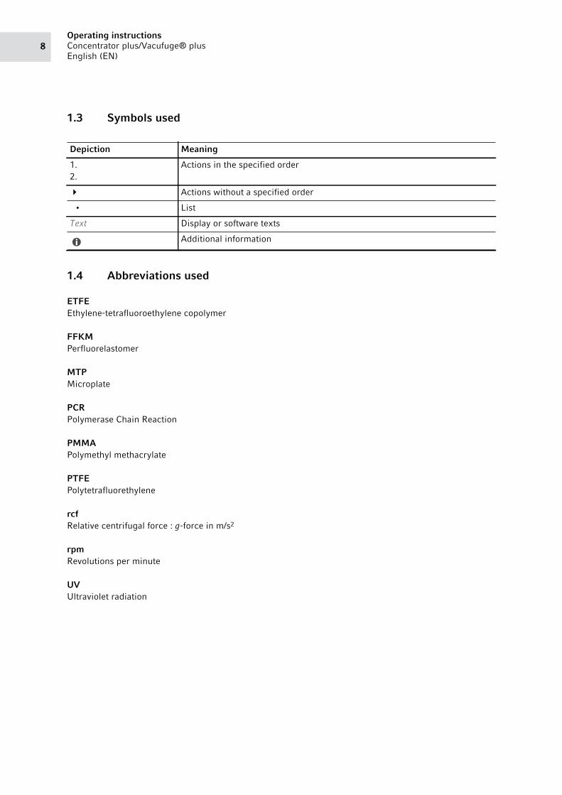
1.3 Symbols used
1.4 Abbreviations used
ETFEEthylene-tetrafluoroethylene copolymer
FFKMPerfluorelastomer
MTPMicroplate
PCRPolymerase Chain Reaction
PMMAPolymethyl methacrylate
PTFEPolytetrafluorethylene
rcfRelative centrifugal force : g-force in m/s2
rpmRevolutions per minute
UVUltraviolet radiation
Depiction Meaning
1.
2.
Actions in the specified order
Actions without a specified order
• List
Text Display or software texts
Additional information
9Safety
Concentrator plus/Vacufuge® plus
English (EN)
2 Safety2.1 Intended use
The Concentrator plus and the Vacufuge plus are intended for sample preparation. They have been
designed in particular for the concentration of aqueous solutions of nucleic acids and proteins in approved
micro test tubes. The devices may only be operated by trained and skilled personnel and are intended for
indoor use only.
2.2 User profile
The device and accessories may only be operated by trained and skilled personnel.
Before using the device, read the operating manual and the instructions for use of the accessories carefully
and familiarize yourself with the device's mode of operation.
2.3 Application limits2.3.1 Declaration concerning the ATEX directive (2014/34/EU)
Due to its design and the environmental conditions inside the device, the Concentrator plus/Vacufuge plus
is not suitable for use in a potentially explosive atmosphere.
The device must be used only in a safe environment, such as in the open environment of a ventilated
laboratory or a fume hood. The use of substances which could create a potentially explosive atmosphere is
not permitted. The final decision on the risks associated with the use of these types of substances is the
user's responsibility.
2.4 Information on product liability
In the following cases, the designated protection of the device may be affected. The liability for any
resulting damage or personal injury is then transferred to the owner:
• The device is not used in accordance with the operating manual.
• The device is used outside of its intended use.
• The device is used with accessories or consumables that are not recommended by Eppendorf.
• The device is maintained or repaired by persons not authorized by Eppendorf AG.
• The user makes unauthorized changes to the device.
DANGER! Risk of explosion.
Do not operate the device in areas where explosive substances are handled.
Do not use this device to process any explosive or highly reactive substances.
Do not use this device to process any substances which may generate an explosive
atmosphere.
SafetyConcentrator plus/Vacufuge® plus
English (EN)10
2.5 Warnings for intended use
Read the operating manual and observe the following general safety information before using the device.
2.5.1 Personal injury or damage to the device
WARNING! Electric shock due to damage to the device or mains/power cord.
Only switch on the device if the device and mains/power cord are undamaged.
Only operate devices which have been installed or repaired properly.
In case of danger, disconnect the device from the mains/power supply voltage. Disconnect
the mains/power plug from the device or the earth/grounded socket. Use the isolating
device intended for this purpose (e.g. the emergency switch in the laboratory).
WARNING! Lethal voltages inside the device.If you touch any parts which are under high voltage you may experience an electric shock.
Electric shocks cause injuries to the heart and respiratory paralysis.
Ensure that the housing is closed and undamaged.
Do not remove the housing.
Ensure that no liquids can penetrate the device.
Only authorized service staff may open the device.
WARNING! Danger due to incorrect voltage supply.
Only connect the device to voltage sources which correspond with the electrical
requirements on the name plate.
Only use earth/grounded sockets with a protective earth (PE) conductor.
Only use the mains/power cord supplied.
WARNING! Damage to health due to infectious liquids and pathogenic germs.
When handling infectious liquids and pathogenic germs, observe the national regulations,
the biosafety level of your laboratory, the material safety data sheets, and the
manufacturer's application notes.
Wear your personal protective equipment.
For comprehensive regulations about handling germs or biological material of risk group II
or higher, please refer to the "Laboratory Biosafety Manual" (source: World Health
Organization, Laboratory Biosafety Manual, the current edition).
WARNING! Burns due to hot micro test tubes and device parts.If the heater is at full power, the wall of the rotor chamber, the rotor and the micro test tubes
will be heated to over 60 °C.
Do not touch the wall of the rotor chamber.
Use suitable protective clothing or auxiliary equipment to remove the micro test tubes.
11Safety
Concentrator plus/Vacufuge® plus
English (EN)
2.5.2 Incorrect handling of the device
NOTICE! Damage to rotors from aggressive chemicals.Rotors are high-quality components which withstand extreme stresses. This stability can be
impaired by aggressive chemicals.
Avoid using aggressive chemicals, including strong and weak alkalis, strong acids,
solutions with mercury, copper and other heavy metal ions, halogenated hydrocarbons,
concentrated saline solutions and phenol.
If the rotor is contaminated by aggressive chemicals, clean it immediately using a neutral
cleaning agent. This applies in particular to the bottom panels of the rotors.
NOTICE! Damage to the device due to spilled liquids.
1. Switch off the device.
2. Disconnect the device from the mains/power supply.
3. Carefully clean the device and the accessories in accordance with the cleaning and
disinfection instructions in the operating manual.
4. If a different cleaning and disinfecting method is to be used, contact Eppendorf AG to
ensure that the intended method will not damage the device.
NOTICE! Damage to the device due to organic solventsThe use of organic solvents may affect some components, e.g. by discolorations.
If this occurs, clean the device immediately using a mild cleaning agent.
NOTICE! Damage to electronic components due to condensation. Condensate may form in the device when it has been transported from a cool environment to a
warmer environment.
After installing the device, wait for at least 3 h. Only then connect the device to the mains/
power line.
WARNING! Fingers may get crushed by the device lid.
Do not reach between the device and lid when opening or closing the device lid.
NOTICE! Damage from knocking against or moving the device during operation.If the rotor hits against the rotor chamber wall, this will cause considerable damage to the
device and rotor.
Do not move or knock against the device during operation.
SafetyConcentrator plus/Vacufuge® plus
English (EN)12
2.5.3 Incorrect handling of the rotors
WARNING! Risk of injury from improperly attached rotors.
Only operate the device if the rotor has been mounted properly.
If there are any unusual noises when the device is started up, stop the concentration
immediately by pressing the start/stop key.
CAUTION! Risk of injury due to asymmetric loading of a rotor.
Always load all positions of a swing-bucket rotor with buckets.
Load buckets symmetrically with identical tubes or plates.
Only load adapters with suitable tubes or plates.
Always use tubes or plates of the same type (weight, material/density and volume).
Ensure that tubes that are located opposite each other contain liquids with the same rate of
evaporation. Otherwise an imbalance may occur and the concentration may be switched
off automatically.
Check that loading is symmetrical by balancing the adapters and tubes or plates used with
a balance.
The device automatically detects imbalances during operation and stops the run immediately
with an error message and a signal tone. Check the loading, balance the tubes and re-start the
centrifugation.
CAUTION! Risk of injury from overloaded rotor.The device is designed for the concentration of substances with a max. density of 1.2 g/mL at
maximum speed and volume.
Observe the maximum load for each rotor (adapter, tube and contents) per rotor bore or
per bucket, and do not exceed this limit.
WARNING! Risk of injury from chemically or mechanically damaged accessories.Even minor scratches and cracks can lead to severe internal material damage.
Protect all accessory parts from mechanical damage.
Inspect the accessories for damage before each use. Replace any damaged accessories.
Do not use rotors or buckets that show signs of corrosion or mechanical damage (e.g.,
deformations).
Do not use accessories that have exceeded their maximum service life.
When inserting the buckets and rotors, ensure that they do not become scratched.
13Safety
Concentrator plus/Vacufuge® plus
English (EN)
2.5.4 Extreme strain on the sample tubes
2.5.5 Vacuum
CAUTION! Risk of injury from overloaded tubes.
Note the loading limits specified by the tube manufacturer.
Only use tubes which are approved by the manufacturer for the required g-forces (rcf).
NOTICE! Risk from damaged tubes.Damaged tubes must not be used as this could cause further damage to the device and the
accessories and loss of the samples.
Visually check all tubes for damage before use.
NOTICE! Damage to plastic tubes due to organic solvents.When using organic solvents (e.g., phenol, chloroform), the strength of plastic tubes may be
reduced and the tubes may become damaged.
Observe the manufacturer’s information on the chemical resistance of the tubes.
NOTICE! Micro test tubes are exposed to strong heat.
Please note the temperature resistance of the micro test tubes.
WARNING! Risk of injury from direct contact with the vacuum.
Do not expose any body parts to the vacuum of the device.
WARNING! Risk of injury due to positive pressure.Positive pressure in the exhaust gas lines (e.g., due to closed taps or blocked lines) may cause
the lines to burst.
Only use lines with a sufficiently large cross section.
Keep the exhaust gas line free at all times.
Do not place any objects on the exhaust gas lines.
Do not bend the exhaust gas lines.
Do not fit any hose clamps or valves to the exhaust gas lines.
Note the maximum pressures and differential pressures permitted (see p. 57).
SafetyConcentrator plus/Vacufuge® plus
English (EN)14
2.6 Safety instructions on the device
WARNING! Damage to health due to escaping substances.No vapors from toxic liquids and pathogenic germs must escape.
Ensure the required condensation and separation of vapors using suitable cold traps or
chemical traps.
Wear personal protective equipment (gloves, clothing, goggles, etc.), ensure proper
ventilation and note the biosafety level of the lab.
Depiction Meaning Location
Notice, observe the operating manual Complete system: On the right side of the
device next to the mains/power
connection.
Basic device: On the rear of the device
next to the mains/power switch.
Risk of explosion
Do not use this device to process any
explosive, radioactive or highly reactive
substances.
Do not use this device to process any
substances which could create an
explosive atmosphere.
On the top of the device.
Risk of scalding when the device lid is openWhen the heater is switched on, the surface
temperature of the rotor chamber can be
>60 °C.
Do not touch the wall of the rotor
chamber.
On the top of the device.
Risk of injury from overpressureThe connection on the top of the emission
condenser is intended as an outlet only.
Make sure that the emission condenser
is connected correctly.
Never shut this connection off.
On the top of the emission condenser.
15Product description
Concentrator plus/Vacufuge® plus
English (EN)
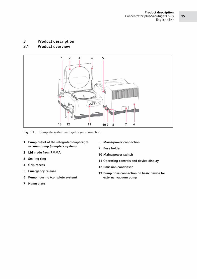
3 Product description3.1 Product overview
Abb. 3-1: Complete system with gel dryer connection
Fig. 3-1: Complete system with gel dryer connection
1 Pump outlet of the integrated diaphragm vacuum pump (complete system)
2 Lid made from PMMA
3 Sealing ring
4 Grip recess
5 Emergency release
6 Pump housing (complete system)
7 Name plate
8 Mains/power connection
9 Fuse holder
10 Mains/power switch
11 Operating controls and device display
12 Emission condenser
13 Pump hose connection on basic device for external vacuum pump
1 2 3 4 5
6111213 78910
Product descriptionConcentrator plus/Vacufuge® plus
English (EN)16
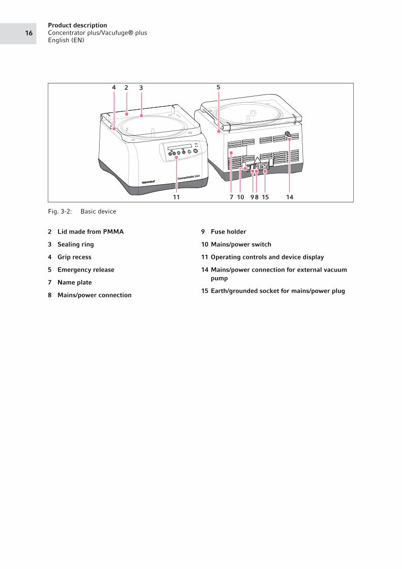
Abb. 3-2: Basic device
Fig. 3-2: Basic device
2 Lid made from PMMA
3 Sealing ring
4 Grip recess
5 Emergency release
7 Name plate
8 Mains/power connection
9 Fuse holder
10 Mains/power switch
11 Operating controls and device display
14 Mains/power connection for external vacuum pump
15 Earth/grounded socket for mains/power plug
4 2 3 5
14158910711
17Product description
Concentrator plus/Vacufuge® plus
English (EN)
3.2 Delivery package
Tab. 3-1: Complete system
Tab. 3-2: Basic device
3.3 Features
The Concentrator plus is designed for the evaporation of liquid or wet samples in micro test tubes,
round-bottom tubes, conical tubes, flat-bottom tubes and different plates.
You can insert the following tubes and plates:
• 1.5 and 2.0 mL micro test tubes in a rotor with 70 positions.
• 0.5 mL micro test tubes in a rotor with 72 positions.
• 5 mL micro test tubes in a rotor with 22 positions.
• 15 mL conical tubes in a rotor with 8 positions.
• 50 mL conical tubes in a rotor with 6 positions.
• MTP and PCR plates in a swing-bucket rotor.
1 Concentrator plus/Vacufuge plus
1 Mains/power cord
1 Emission condenser
1 Hose for emission condenser
1 Hose connection
1 Angle connection
1 Set of fuses
1 Instructions
1 Concentrator plus/Vacufuge plus
1 Mains/power cord
1 Set of fuses
1 Instructions
Check whether the delivery is complete.
Check all parts for any transport damage.
To safely transport and store the device, retain the transport box and packing material.

Product descriptionConcentrator plus/Vacufuge® plus
English (EN)18
A complete list can be found in the following chapter (see Rotors on p. 58).
The device is available as a complete system with an integrated diaphragm vacuum pump or as a basic
device without a vacuum pump. The basic device can be connected to an external vacuum system.
The Concentrator plus has the following functions:
• 3 temperature levels can be set (30, 45, 60 °C). Alternatively, evacuation is carried out without
temperature control.
• The evaporation of liquids can be carried out optimized in 3 functions. In addition to pure evacuation,
aqueous and/or alcoholic solutions can be concentrated extra fast with 2 special functions.
• You can also operate the device as a pure desiccator.
• You can connect a solvent trap to the device behind the pump.
19Product description
Concentrator plus/Vacufuge® plus
English (EN)
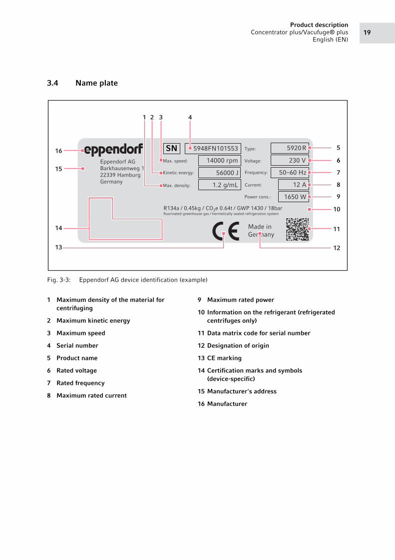
3.4 Name plate
Abb. 3-3: Eppendorf AG device identification (example)
Fig. 3-3: Eppendorf AG device identification (example)
1 Maximum density of the material for centrifuging
2 Maximum kinetic energy
3 Maximum speed
4 Serial number
5 Product name
6 Rated voltage
7 Rated frequency
8 Maximum rated current
9 Maximum rated power
10 Information on the refrigerant (refrigerated centrifuges only)
11 Data matrix code for serial number
12 Designation of origin
13 CE marking
14 Certification marks and symbols (device-specific)
15 Manufacturer's address
16 Manufacturer
Eppendorf AG
Barkhausenweg 1
22339 Hamburg
Germany
Made in
Germany
5920 R 5948FN101553
Current:
50–60 Hz
1650 W
14000 rpm
56000 J
1.2 g/mL
Max. speed:
Kinetic energy:
Max. density: 12 A
Voltage: 230 V
Frequency:
Power cons.:
Type:
R134a / 0.45kg / CO2e 0.64t / GWP 1430 / 18bar greenhouse gas / hermetically sealed refrigeration system
SN
fluorinated
16
15
5
6
7
8
9
10
11
1213
14
31 2 4
Product descriptionConcentrator plus/Vacufuge® plus
English (EN)20
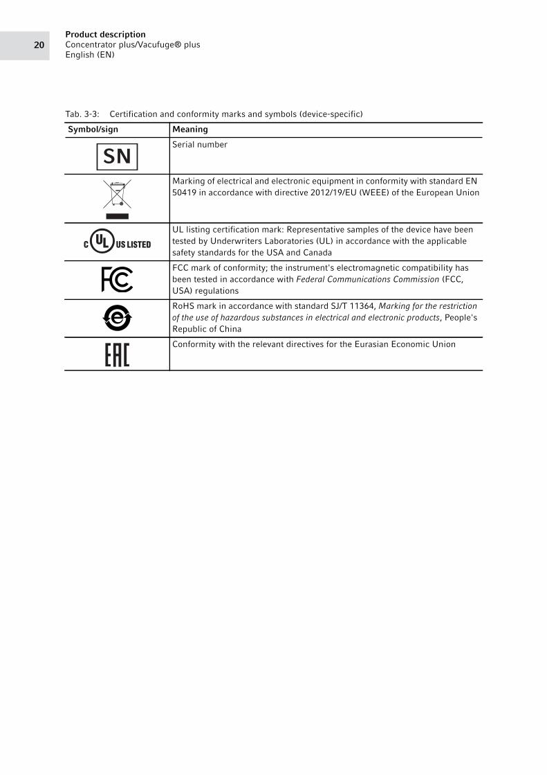
Tab. 3-3: Certification and conformity marks and symbols (device-specific)
Symbol/sign Meaning
Serial number
Marking of electrical and electronic equipment in conformity with standard EN
50419 in accordance with directive 2012/19/EU (WEEE) of the European Union
UL listing certification mark: Representative samples of the device have been
tested by Underwriters Laboratories (UL) in accordance with the applicable
safety standards for the USA and Canada
FCC mark of conformity; the instrument's electromagnetic compatibility has
been tested in accordance with Federal Communications Commission (FCC,
USA) regulations
RoHS mark in accordance with standard SJ/T 11364, Marking for the restriction
of the use of hazardous substances in electrical and electronic products, People's
Republic of China
Conformity with the relevant directives for the Eurasian Economic Union
SN
21Installation
Concentrator plus/Vacufuge® plus
English (EN)
4 Installation4.1 Selecting the location
WARNING! Danger due to incorrect voltage supply.
Only connect the device to voltage sources which correspond with the electrical
requirements on the name plate.
Only use earth/grounded sockets with a protective earth (PE) conductor.
Only use the mains/power cord supplied.
NOTICE! If an error occurs, objects in the immediate vicinity of the device may become damaged.
In accordance with the recommendations of EN 61010-2-020, leave a safety clearance of
30 cm around the device during operation.
Please remove all materials and objects from this area.
NOTICE! Damage due to overheating.
Do not position the device near heat sources (e.g., heating, drying cabinets).
Do not expose the device to direct sunlight.
Ensure unobstructed air circulation. On all sides of the device, ensure that there is a
minimum gap of 30 cm not obstructed to adjacent devices or to the wall. Ensure that the
bottom of the device is not obstructed.
Always keep the ventilation gaps of the device free from obstructions.
NOTICE! Radio interference.For devices with Class A noise emission in accordance with EN 61326-1/EN 55011, the
following applies: This device has been developed and tested in accordance with CISPR 11
Class A. The device may cause radio interference in domestic environments and is not
intended for use in residential areas. The device cannot ensure adequate protection of radio
reception in residential areas and domestic environments.
If necessary, take appropriate measure to eliminate the interferences.
The mains/power switch and the disconnecting device of the mains/power line must be easily
accessible during operation (e.g. a residual current circuit breaker).
Mains/power connection for the concentrator: Operation of the concentrator is only permitted
in building installations that comply with the applicable national regulations and standards. In
particular, it must be ensured that there are no impermissible loads on the supply lines and
assemblies that are located upstream of the internal protection of the device. This can be
ensured by additional circuit breakers or other suitable safety elements in the building
installation.
InstallationConcentrator plus/Vacufuge® plus
English (EN)22
Select the location for the device according to the following criteria:
• Suitable mains/power connection in accordance with the name plate
• Minimum distance to other devices and walls: 30 cm
• Resonance free table with horizontal even work surface
• The location must be well ventilated
• The location is protected against direct sunlight
• Ambient temperature during operation: 15 to 35 °C
• At altitudes above 1000 m MSL, measures to ensure the supply of cooling air in accordance with DIN
EN 60034-1; VDE 0530-1 are required
4.2 Preparing installation
Please complete the following steps in the order described:
1. Open the packaging board.
2. Remove the accessories and rotors.
3. Cut the strap retainers.
4. Lift the device with the transport protection pad out of the box and place it on a stable, level and
non-resonant lab bench.
5. Carefully place the device with the transport protection pad on its side.
The mains/power switch and the disconnecting device of the mains/power line must be easily
accessible during operation (e.g., residual current circuit breaker).
WARNING! Risk of injury from operating an incorrectly installed device.The device is not ready for operation after it has been installed. Additional components are
missing.
Read the following chapter before operating the device (see General installation on p. 24).
The weight of the complete system is 31.5 kg. The weight of the basic device is 16.5 kg.
• Two persons are always required to transport and install the device.
• Only transport the device in its original packing.
• Use a transport aid for longer distances (e.g., hand truck).
• Keep the packaging board and the transport securing device for later transport or storage.
See also the instructions relating to transport (see p. 53).
23Installation
Concentrator plus/Vacufuge® plus
English (EN)
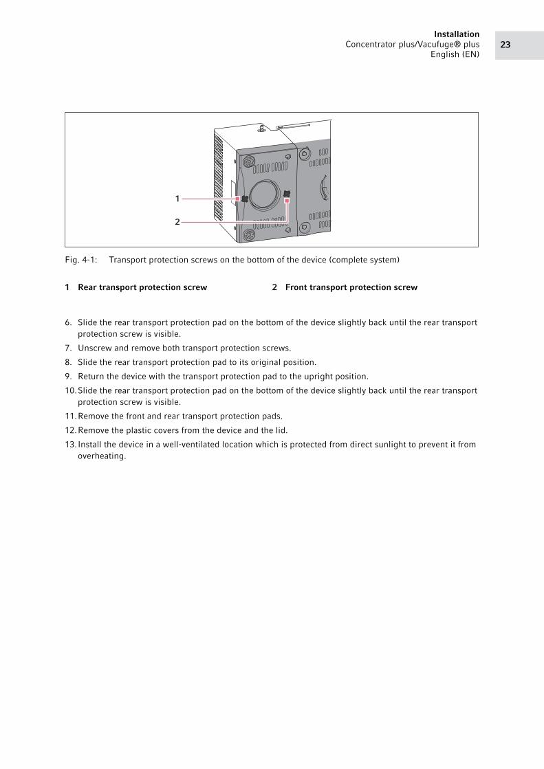
Abb. 4-1: Transport protection screws on the bottom of the device (complete system)
Fig. 4-1: Transport protection screws on the bottom of the device (complete system)
6. Slide the rear transport protection pad on the bottom of the device slightly back until the rear transport
protection screw is visible.
7. Unscrew and remove both transport protection screws.
8. Slide the rear transport protection pad to its original position.
9. Return the device with the transport protection pad to the upright position.
10.Slide the rear transport protection pad on the bottom of the device slightly back until the rear transport
protection screw is visible.
11.Remove the front and rear transport protection pads.
12.Remove the plastic covers from the device and the lid.
13.Install the device in a well-ventilated location which is protected from direct sunlight to prevent it from
overheating.
1 Rear transport protection screw 2 Front transport protection screw
1
2
InstallationConcentrator plus/Vacufuge® plus
English (EN)24
4.3 Installing the instrument4.3.1 General installation
WARNING! Danger due to incorrect voltage supply.
Only connect the device to voltage sources which correspond with the electrical
requirements on the name plate.
Only use earth/grounded sockets with a protective earth (PE) conductor.
Only use the mains/power cord supplied.
WARNING! Damage to health due to escaping substances.No vapors from toxic liquids and pathogenic germs must escape.
Ensure the required condensation and separation of vapors using suitable cold traps or
chemical traps.
Wear personal protective equipment (gloves, clothing, goggles, etc.), ensure proper
ventilation and note the biosafety level of the lab.
NOTICE! Damage to electronic components due to condensation. Condensate may form in the device when it has been transported from a cool environment to a
warmer environment.
After installing the device, wait for at least 3 h. Only then connect the device to the mains/
power line.
Select a setup for the collection and/or discharge of liquids and gases which complies with the
applicable legal requirements and regulations for your application.
25Installation
Concentrator plus/Vacufuge® plus
English (EN)
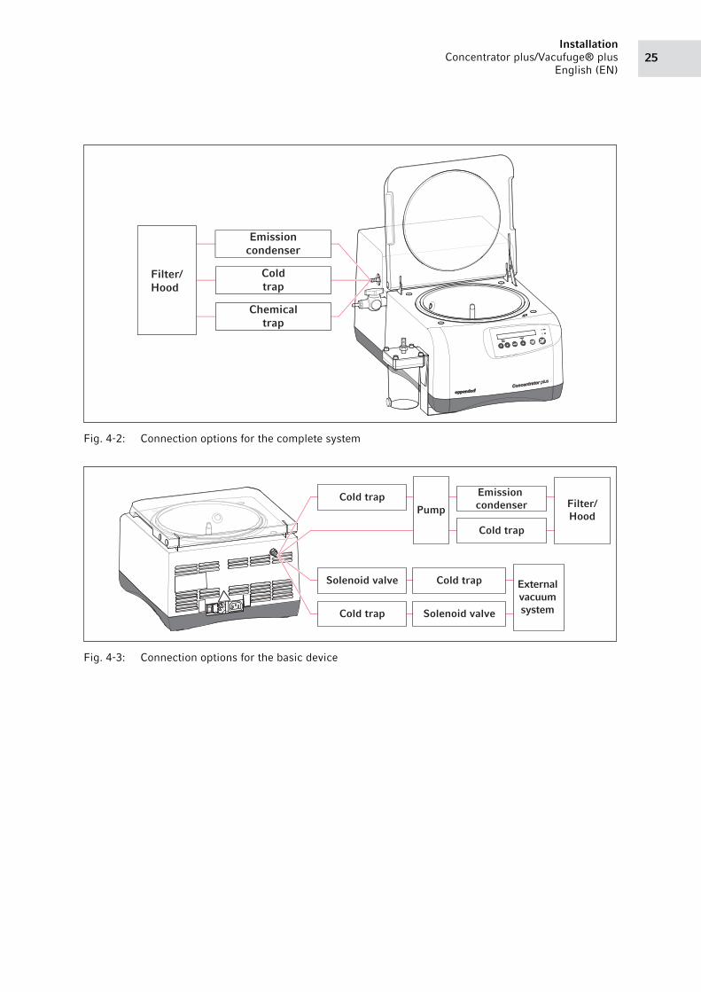
Abb. 4-2: Connection options for the complete system
Fig. 4-2: Connection options for the complete system
Abb. 4-3: Connection options for the basic device
Fig. 4-3: Connection options for the basic device
Filter/Hood
Emissioncondenser
Coldtrap
Chemicaltrap
Cold trap
Cold trap
Cold trap
Cold trap
Pump Filter/Hood
External vacuum system Solenoid valve
Emission condenser
Solenoid valve
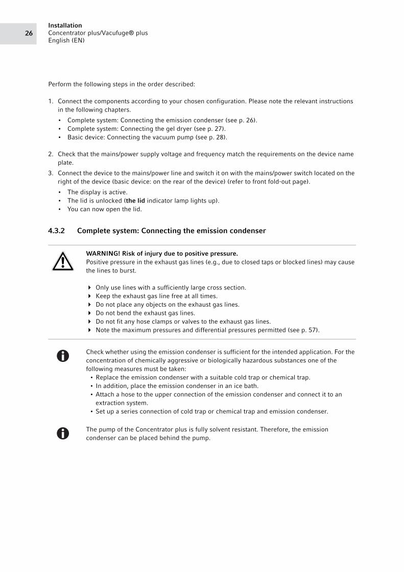
InstallationConcentrator plus/Vacufuge® plus
English (EN)26
Perform the following steps in the order described:
1. Connect the components according to your chosen configuration. Please note the relevant instructions
in the following chapters.
• Complete system: Connecting the emission condenser (see p. 26).
• Complete system: Connecting the gel dryer (see p. 27).
• Basic device: Connecting the vacuum pump (see p. 28).
2. Check that the mains/power supply voltage and frequency match the requirements on the device name
plate.
3. Connect the device to the mains/power line and switch it on with the mains/power switch located on the
right of the device (basic device: on the rear of the device) (refer to front fold-out page).
• The display is active.
• The lid is unlocked (the lid indicator lamp lights up).
• You can now open the lid.
4.3.2 Complete system: Connecting the emission condenser
WARNING! Risk of injury due to positive pressure.Positive pressure in the exhaust gas lines (e.g., due to closed taps or blocked lines) may cause
the lines to burst.
Only use lines with a sufficiently large cross section.
Keep the exhaust gas line free at all times.
Do not place any objects on the exhaust gas lines.
Do not bend the exhaust gas lines.
Do not fit any hose clamps or valves to the exhaust gas lines.
Note the maximum pressures and differential pressures permitted (see p. 57).
Check whether using the emission condenser is sufficient for the intended application. For the
concentration of chemically aggressive or biologically hazardous substances one of the
following measures must be taken:
• Replace the emission condenser with a suitable cold trap or chemical trap.
• In addition, place the emission condenser in an ice bath.
• Attach a hose to the upper connection of the emission condenser and connect it to an
extraction system.
• Set up a series connection of cold trap or chemical trap and emission condenser.
The pump of the Concentrator plus is fully solvent resistant. Therefore, the emission
condenser can be placed behind the pump.
27Installation
Concentrator plus/Vacufuge® plus
English (EN)
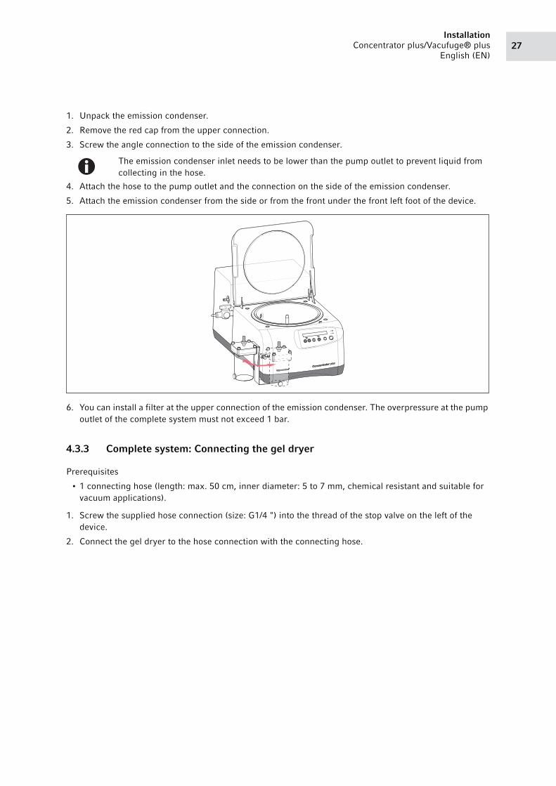
1. Unpack the emission condenser.
2. Remove the red cap from the upper connection.
3. Screw the angle connection to the side of the emission condenser.
4. Attach the hose to the pump outlet and the connection on the side of the emission condenser.
5. Attach the emission condenser from the side or from the front under the front left foot of the device.
6. You can install a filter at the upper connection of the emission condenser. The overpressure at the pump
outlet of the complete system must not exceed 1 bar.
4.3.3 Complete system: Connecting the gel dryer
Prerequisites
• 1 connecting hose (length: max. 50 cm, inner diameter: 5 to 7 mm, chemical resistant and suitable for
vacuum applications).
1. Screw the supplied hose connection (size: G1/4 ") into the thread of the stop valve on the left of the
device.
2. Connect the gel dryer to the hose connection with the connecting hose.
The emission condenser inlet needs to be lower than the pump outlet to prevent liquid from
collecting in the hose.
InstallationConcentrator plus/Vacufuge® plus
English (EN)28
4.3.4 Basic device: Connecting the vacuum pump
The basic device can be connected to an external vacuum pump.
Prerequisites• The vacuum pump is approved in accordance with the applicable standards in your country.
• A condenser (e.g., emission condenser, cold trap or chemical trap) between the devices or behind the
vacuum pump, depending on your application.
• The pump withstands an ultimate pressure of at least 20 mbar. Its suction capacity is at least 1.8 m³/h.
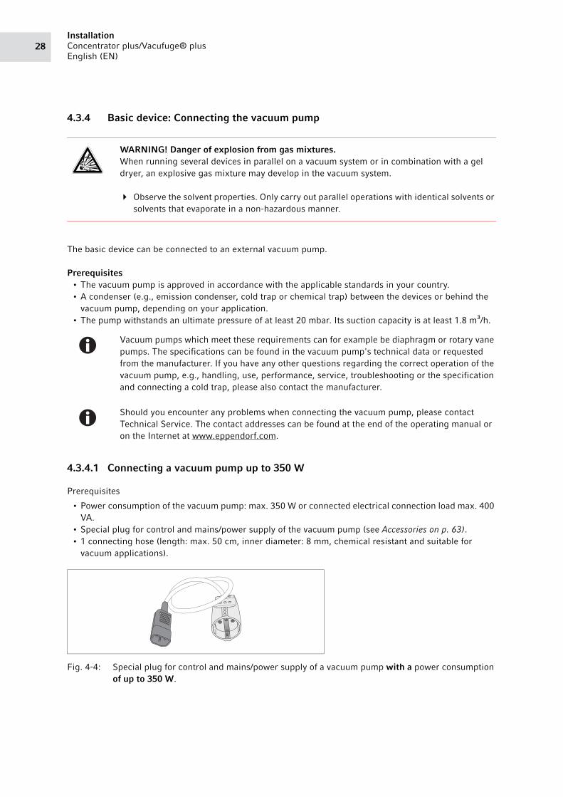
4.3.4.1 Connecting a vacuum pump up to 350 W
Prerequisites
• Power consumption of the vacuum pump: max. 350 W or connected electrical connection load max. 400
VA.
• Special plug for control and mains/power supply of the vacuum pump (see Accessories on p. 63).
• 1 connecting hose (length: max. 50 cm, inner diameter: 8 mm, chemical resistant and suitable for
vacuum applications).
Abb. 4-4: Special plug for control and mains/power supply of a vacuum pump with a power consumption of up to 350 W.
Fig. 4-4: Special plug for control and mains/power supply of a vacuum pump with a power consumption
of up to 350 W.
WARNING! Danger of explosion from gas mixtures.When running several devices in parallel on a vacuum system or in combination with a gel
dryer, an explosive gas mixture may develop in the vacuum system.
Observe the solvent properties. Only carry out parallel operations with identical solvents or
solvents that evaporate in a non-hazardous manner.
Vacuum pumps which meet these requirements can for example be diaphragm or rotary vane
pumps. The specifications can be found in the vacuum pump's technical data or requested
from the manufacturer. If you have any other questions regarding the correct operation of the
vacuum pump, e.g., handling, use, performance, service, troubleshooting or the specification
and connecting a cold trap, please also contact the manufacturer.
Should you encounter any problems when connecting the vacuum pump, please contact
Technical Service. The contact addresses can be found at the end of the operating manual or
on the Internet at www.eppendorf.com.
29Installation
Concentrator plus/Vacufuge® plus
English (EN)
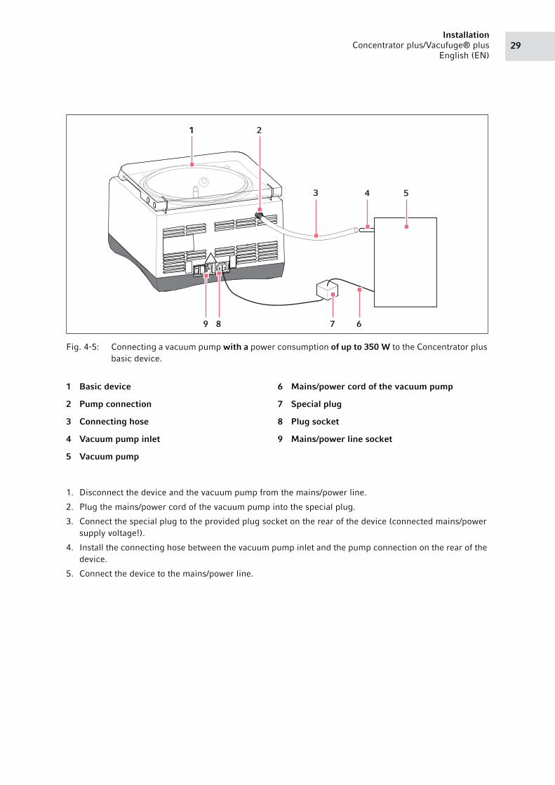
Abb. 4-5: Connecting a vacuum pump with a power consumption of up to 350 W to the Concentrator plus basic device.
Fig. 4-5: Connecting a vacuum pump with a power consumption of up to 350 W to the Concentrator plus
basic device.
1. Disconnect the device and the vacuum pump from the mains/power line.
2. Plug the mains/power cord of the vacuum pump into the special plug.
3. Connect the special plug to the provided plug socket on the rear of the device (connected mains/power
supply voltage!).
4. Install the connecting hose between the vacuum pump inlet and the pump connection on the rear of the
device.
5. Connect the device to the mains/power line.
1 Basic device
2 Pump connection
3 Connecting hose
4 Vacuum pump inlet
5 Vacuum pump
6 Mains/power cord of the vacuum pump
7 Special plug
8 Plug socket
9 Mains/power line socket
11 2
3 4 5
689 7
InstallationConcentrator plus/Vacufuge® plus
English (EN)30
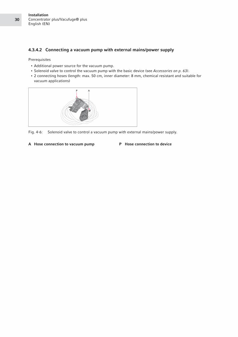
4.3.4.2 Connecting a vacuum pump with external mains/power supply
Prerequisites
• Additional power source for the vacuum pump.
• Solenoid valve to control the vacuum pump with the basic device (see Accessories on p. 63).
• 2 connecting hoses (length: max. 50 cm, inner diameter: 8 mm, chemical resistant and suitable for
vacuum applications)
Abb. 4-6: Solenoid valve to control a vacuum pump with external mains/power supply.
Fig. 4-6: Solenoid valve to control a vacuum pump with external mains/power supply.
A Hose connection to vacuum pump P Hose connection to device
P A
31Installation
Concentrator plus/Vacufuge® plus
English (EN)
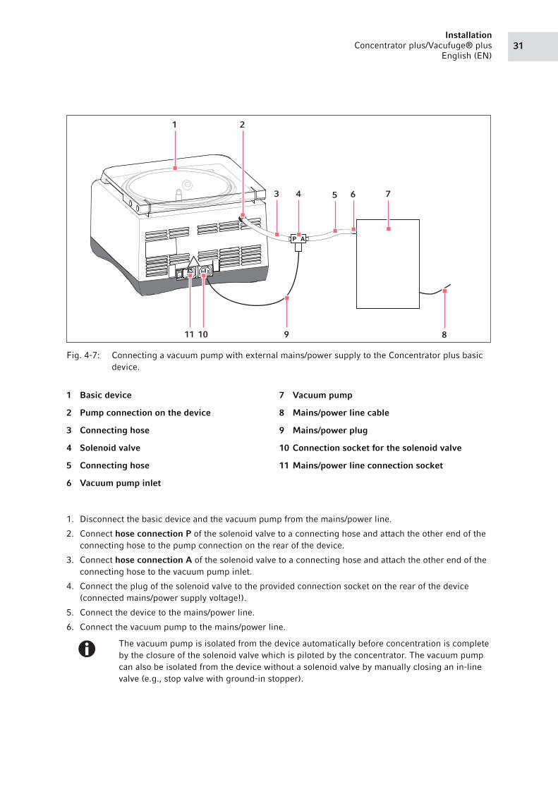
Abb. 4-7: Connecting a vacuum pump with external mains/power supply to the Concentrator plus basic device.
Fig. 4-7: Connecting a vacuum pump with external mains/power supply to the Concentrator plus basic
device.
1. Disconnect the basic device and the vacuum pump from the mains/power line.
2. Connect hose connection P of the solenoid valve to a connecting hose and attach the other end of the
connecting hose to the pump connection on the rear of the device.
3. Connect hose connection A of the solenoid valve to a connecting hose and attach the other end of the
connecting hose to the vacuum pump inlet.
4. Connect the plug of the solenoid valve to the provided connection socket on the rear of the device
(connected mains/power supply voltage!).
5. Connect the device to the mains/power line.
6. Connect the vacuum pump to the mains/power line.
1 Basic device
2 Pump connection on the device
3 Connecting hose
4 Solenoid valve
5 Connecting hose
6 Vacuum pump inlet
7 Vacuum pump
8 Mains/power line cable
9 Mains/power plug
10 Connection socket for the solenoid valve
11 Mains/power line connection socket
The vacuum pump is isolated from the device automatically before concentration is complete
by the closure of the solenoid valve which is piloted by the concentrator. The vacuum pump
can also be isolated from the device without a solenoid valve by manually closing an in-line
valve (e.g., stop valve with ground-in stopper).
P A
1 2
3 4 5 6 7
891011

InstallationConcentrator plus/Vacufuge® plus
English (EN)32
33Operation
Concentrator plus/Vacufuge® plus
English (EN)
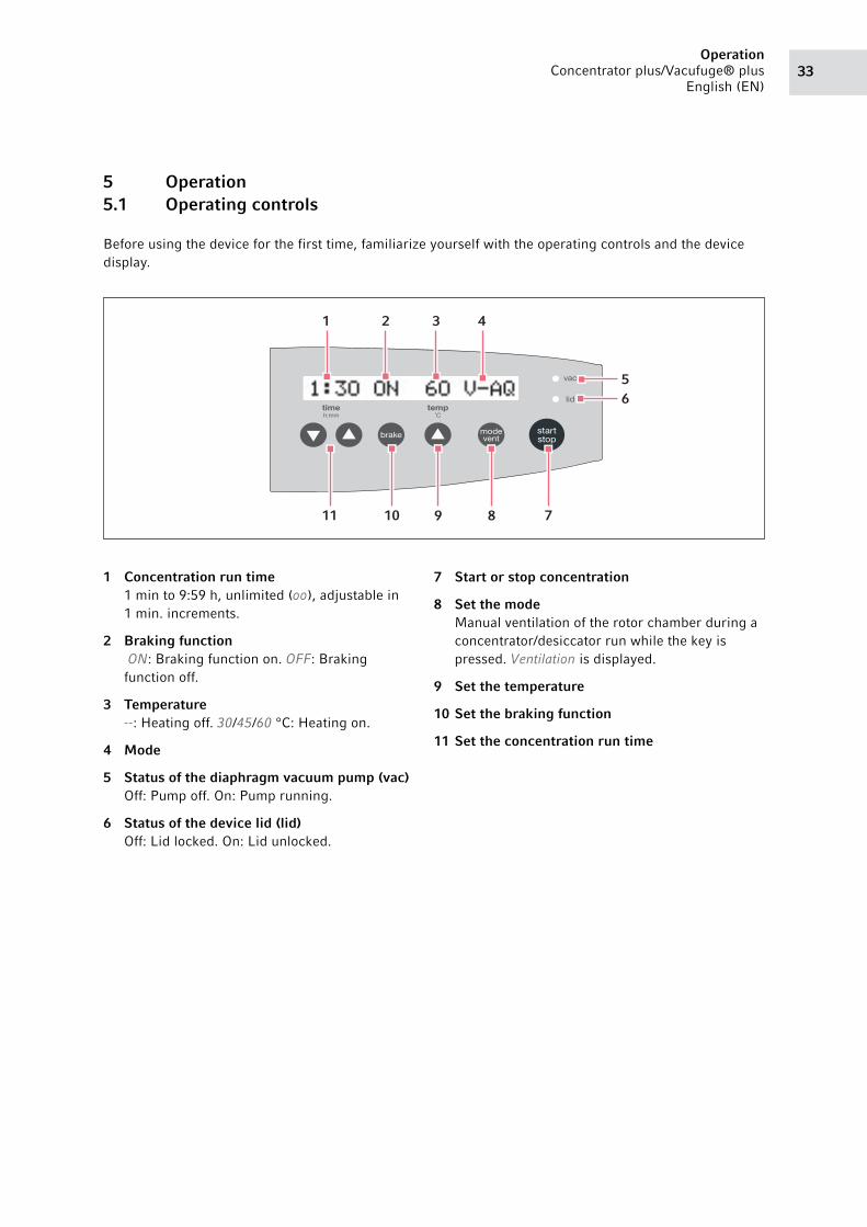
5 Operation5.1 Operating controls
Before using the device for the first time, familiarize yourself with the operating controls and the device
display.
1 Concentration run time1 min to 9:59 h, unlimited (oo), adjustable in
1 min. increments.
2 Braking function ON: Braking function on. OFF: Braking
function off.
3 Temperature--: Heating off. 30/45/60 °C: Heating on.
4 Mode
5 Status of the diaphragm vacuum pump (vac)Off: Pump off. On: Pump running.
6 Status of the device lid (lid)Off: Lid locked. On: Lid unlocked.
7 Start or stop concentration
8 Set the modeManual ventilation of the rotor chamber during a
concentrator/desiccator run while the key is
pressed. Ventilation is displayed.
9 Set the temperature
10 Set the braking function
11 Set the concentration run time
7891011
56
1 2 3 4

OperationConcentrator plus/Vacufuge® plus
English (EN)34
5.2 Possible applications
The device can be used as a concentrator, a desiccator, or a centrifuge. For the concentrator and desiccator
functions, there are three different modes available for the quick concentration of different solvents:
To set the desired function, press the mode/vent key before operation of the device.
5.3 Preparation for concentration5.3.1 Switching on the device
Switch on the device at the mains/power switch.
• The display is active.
• The lid is released (the lid indicator lamp lights up).
• You can now open the lid.
• The parameter settings of the last run are displayed.
Function Mode Suitable for
Concentrator V-AQ (vacuum -
aqueous)
Aqueous solutions
V-AL (vacuum -
alcoholic)
Alcoholic solutions
V-HV (vacuum - high
vapor)
Solutions with high vapor pressure
Desiccator D-AQ (desiccator -
aqueous)
Aqueous solutions
D-AL (desiccator -
alcoholic)
Alcoholic solutions
D-HV (desiccator - high
vapor)
Solutions with high vapor pressure and dry
substances
Centrifuge CEFU (centrifuge) Centrifugation at 1,400 min-1
Use the V-AQ, V-AL, D-AQ or D-AL modes if possible, or press the mode/vent key from time to
time during the run.
During operation, you cannot change the set function. Instead, holding the mode/vent key
during the concentrator or desiccator function ventilates the rotor chamber.
Please note before putting the device into operation that the ambient temperature during
operation must be between 15 and 35 °C.
At altitudes above 1000 m MSL, measures to ensure the supply of cooling air in accordance
with DIN EN 60034-1; VDE 0530-1 are required.
35Operation
Concentrator plus/Vacufuge® plus
English (EN)
5.3.2 Inserting the rotor
Proceed as follows when inserting the rotor:
1. Place the rotor on the motor shaft.
2. Push the rotor down using slight pressure until you encounter resistance.
5.3.3 Starting the warm-up phase
The diaphragm vacuum pump reaches the displayed output and the ultimate pressure (see p. 57)only after
the device has gone through a 15-minute warm-up phase. The warm-up phase reduces the condensation of
liquid in the pump and on the lid of the rotor chamber and therefore prolongs the service life of the pump.
1. time arrow keys: set the time to 15 minutes.
2. brake: switch the brake on or off.
3. temp: select the temperature.
4. mode/vent: select the V-AQ, V-AL or V-HV mode.
5. Close the lid of the device.
6. Press start/stop to start the warm-up phase.
• The device lid is locked, and the blue lid indicator lamp goes out.
• The rotor starts up.
• At 1,000 rpm, the vacuum pump switches on, and the vac indicator lamp lights up.
• The vent valve is closed.
• The rotor accelerates to the end point of 1,400 rpm.
• On the display, the colon in the time display flashes while the rotor is turning.
• The remaining run time is displayed in hours and minutes.
First observe the rotor information and the special notes on rotors F-35-6-30, F-45-72-8,
F-45-48-11, F-45-24-12 and A-2-VC (see p. 61).
Rotor A-2-VC: remove the buckets before inserting the rotor and pick it up at the rotor cross
using both hands.
The rotors do not need to be screwed in.
WARNING! Fingers may get crushed by the device lid.
Do not reach between the device and lid when opening or closing the device lid.
OperationConcentrator plus/Vacufuge® plus
English (EN)36
After the warm-up phase is completed• The device stops automatically.
• During braking, the elapsed concentration time flashes on the display.
• The rotor chamber is ventilated so that the pressure in the chamber increases slowly.
• After two seconds, the vacuum pump switches off, and the vac indicator lamp goes out.
• Then the device brakes.
• When the rotor has come to a standstill, the lid indicator lamp lights up.
• The lid can be opened.
5.3.4 Loading a fixed-angle rotor
The following notes apply to fixed-angle rotors. Loading the rotor A-2-VC is described in the following
chapter (see Loading a swing-bucket rotor on p. 37).
Proceed as follows when loading the fixed-angle rotor:
1. Check the maximum payload (tube and content) per rotor bore. Detailed information can be found in
this operating manual (see Rotors on p. 58).
2. Only load rotors with the tubes intended for this purpose.
3. Insert open tubes opposite each other in pairs into the rotor bores. To ensure symmetrical loading,
tubes that are arranged opposite each other must be of the same type and contain the same filling
quantity.
In order to minimize weight differences between the filled micro test tubes, we recommend taring with
a balance. This will reduce wear on the drive and cut operating noise.
CAUTION! Risk of injury due to asymmetric loading of a rotor.
Always load all positions of a swing-bucket rotor with buckets.
Load buckets symmetrically with identical tubes or plates.
Only load adapters with suitable tubes or plates.
Always use tubes or plates of the same type (weight, material/density and volume).
Ensure that tubes that are located opposite each other contain liquids with the same rate of
evaporation. Otherwise an imbalance may occur and the concentration may be switched
off automatically.
Check that loading is symmetrical by balancing the adapters and tubes or plates used with
a balance.
The device automatically detects imbalances during operation and stops the run immediately
with an error message and a signal tone. Check the loading, balance the tubes and re-start the
centrifugation.
CAUTION! Risk from damaged or overloaded tubes.
When loading the rotor, observe the safety instructions for hazards resulting from
overloaded or damaged tubes.
37Operation
Concentrator plus/Vacufuge® plus
English (EN)
5.3.5 Loading a swing-bucket rotor
Prerequisites
• A rotor, bucket and adapter combination approved by Eppendorf.
• Two inserted buckets.
• Matching and tested tubes and plates.
• Adapters and plates with a total height of ≤ 27 mm.
1. Check the bucket grooves for cleanliness and grease them lightly with pivot grease (order no. int.: 5810
350.050/North America: 022634330).
Dirty grooves and pivots prevent the buckets from swinging out evenly.
2. Hang the buckets into the rotor.
3. Check that both buckets are hanging properly and can swing out freely.
4. When using a plate type for the first time, carry out a manual loading and swing-out test.
5. Check the maximum payload (adapter, plate and content) per bucket.
The relevant details can be found on the rotor and in this operating manual (see Rotors on p. 58).
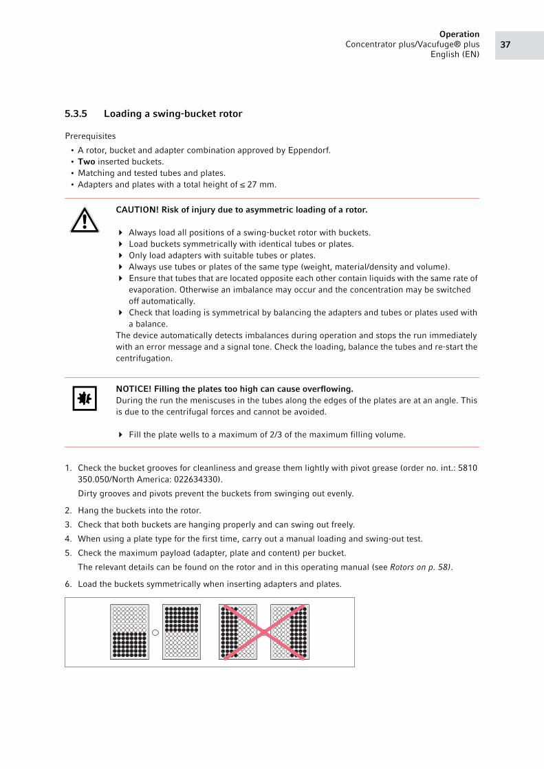
6. Load the buckets symmetrically when inserting adapters and plates.
CAUTION! Risk of injury due to asymmetric loading of a rotor.
Always load all positions of a swing-bucket rotor with buckets.
Load buckets symmetrically with identical tubes or plates.
Only load adapters with suitable tubes or plates.
Always use tubes or plates of the same type (weight, material/density and volume).
Ensure that tubes that are located opposite each other contain liquids with the same rate of
evaporation. Otherwise an imbalance may occur and the concentration may be switched
off automatically.
Check that loading is symmetrical by balancing the adapters and tubes or plates used with
a balance.
The device automatically detects imbalances during operation and stops the run immediately
with an error message and a signal tone. Check the loading, balance the tubes and re-start the
centrifugation.
NOTICE! Filling the plates too high can cause overflowing.During the run the meniscuses in the tubes along the edges of the plates are at an angle. This
is due to the centrifugal forces and cannot be avoided.
Fill the plate wells to a maximum of 2/3 of the maximum filling volume.
OperationConcentrator plus/Vacufuge® plus
English (EN)38
The plate arrangement shown on the right-hand side is incorrect as the buckets will not swing out
properly.
The plates have some play in the buckets.
5.3.6 Closing the lid of the device
1. Check that the rotor is correctly positioned.
2. Close the lid of the device.
5.4 Starting the concentration process
Each of the applications described here must be preceded by the preparation described above (see
Preparation for concentration on p. 34).
WARNING! Fingers may get crushed by the device lid.
Do not reach between the device and lid when opening or closing the device lid.
WARNING! Risk of injury from improperly attached rotors.
Only operate the device if the rotor has been mounted properly.
If there are any unusual noises when the device is started up, stop the concentration
immediately by pressing the start/stop key.
CAUTION! Danger due to incorrectly loaded rotors and damaged/overloaded tubes!
Before commencing concentration, follow the safety instructions relating to risks from
asymmetrically loaded and/or overloaded rotors and from overloaded and/or damaged
tubes.
NOTICE! Overflowing of the emission condenser.The maximum filling volume of the emission condenser is 280 mL.
1. Check before each run whether the volume of the emission condenser is sufficient for your
application.
2. Empty the emission condenser if necessary.
Unusual noises may occur when braking heavy rotors. This is construction-related and does
not indicate a problem.
If a temperature has been set, the rotor chamber is heated continuously, i.e., even when the
rotor has stopped and the lid is open. Therefore, switch the device off after completing the
application or set the temperature to - - (no temperature set), if applicable.

39Operation
Concentrator plus/Vacufuge® plus
English (EN)
5.4.1 Starting the concentration process with time setting
Perform the following steps in the order described:
1. time arrow keys: set the run time.
2. brake: switch the brake on or off.
3. temp: select the temperature (note the temperature resistance of the samples).
4. mode/vent: select the V-AQ, V-AL or V-HV mode.
5. start/stop: start the concentration process.
• The device lid is locked, the blue lid indicator lamp goes out.
• The rotor starts accelerating.
• At 1,000 rpm, the vacuum pump starts, and the vac indicator lamp lights up.
• The vent valve closes.
• The rotor accelerates to the end point of 1,400 rpm.
• On the display, the colon in the time display flashes while the rotor is turning.
• The remaining run time is displayed in hours and minutes.
5.4.2 Starting the concentration process with continuous run
Use the continuous run function if you do not want to set a fixed run time .
1. Use the time arrow keys to set the continuous run function (oo), this can be achieved below 0:01 or above
9:59.
2. Set all other parameters as described above (see Starting the concentration process with time setting on
p. 39).
3. Press start/stop to start the concentration process.
The time is counted up in increments of 1 minute.
4. Press start/stop to end the concentration process after the desired time period.
During a concentration process you can:
• Change the total run time. The new parameters are adopted immediately. Please note that
the shortest new total run time that can be set is the elapsed time plus 2 minutes.
• Adjust the braking function.
• Adjust the temperature.
• Manually ventilate the rotor chamber by keeping the mode/vent key pressed. This will
remove condensation from the device lid and flush the pump and the hose system.
CAUTION! Continuous operation may affect the safe operation of the device.If operated continuously to deliver liquids, the membranes and valves of the vacuum pump
may become damaged.
Only use the device for applications of limited duration.
If the device runs for more than 9:59 h, 9:59 remains on the display.
OperationConcentrator plus/Vacufuge® plus
English (EN)40
5.4.3 Completing the concentration process
After completion of the concentration process:• The device stops automatically (time setting) or manually (continuous run).
• The elapsed concentration time flashes on the display during the braking process.
• The rotor chamber is ventilated so that the pressure in the chamber increases slowly.
• After two seconds, the vacuum pump switches off, and the vac indicator lamp goes out.
• The device then decelerates.
• After the rotor has stopped, the lid indicator lamp lights up.
• The lid can be opened and the samples removed.
1. Open the lid and remove the samples.
2. Close the lid.
3. Let the device continue to run in D-AQ mode with an empty rotor for 15 minutes after completing the
application.
5.4.4 Removing the rotor
1. Switch the heating off if applicable.
2. Remove the rotor.
3. Wipe up any spilled liquid in the rotor chamber and on the device lid with an absorbent cloth.
4. Clean the rotor chamber and the device lid as described separately.
5.4.5 Emptying the emission condenser
1. There are two possibilities, depending on the design:
• The emission condenser is mounted to the side of the device: Pull the tubing from the connection
and empty the liquid into a collection vessel through the upper connection.
• The emission condenser is mounted to the front of the device: Here you can remove the black
plug in the vessel with a screwdriver and fit a separate tap before using the device for the first time.
You can then empty the liquid directly into a collection vessel via this tap.
2. Dispose of the liquid in accordance with the current legal requirements and regulations for your
application.
5.4.6 Switching off the device
1. Leave the device lid open and secure it against closing to allow any remaining liquid to evaporate.
2. Switch off the device at the mains/power switch.
Rotor A-2-VC: First remove the buckets, then grip the rotor at the rotor cross with both hands
to lift it out of the device.
41Operation
Concentrator plus/Vacufuge® plus
English (EN)
5.5 User instructions on rotors5.5.1 Rotor A-2-VC5.5.1.1 Transferring the rotor
CAUTION! Wait for the rotor to stop.If the plates are fully loaded, it may be possible to open the device lid during the post-run
phase of the A-2-VC rotor before the rotor stops.
Always wait for the rotor to stop before opening the device lid and removing the plates or
tubes.
NOTICE! If handled incorrectly, the rotor may fall.The swing-bucket rotor may fall if the buckets are used as handles.
Remove the buckets before inserting and/or removing a swing-bucket rotor.
Always use both hands to carry the rotor cross.
OperationConcentrator plus/Vacufuge® plus
English (EN)42
5.6 Special function5.6.1 Starting the desiccator function on the device
With the desiccator function the rotor chamber is evacuated. However, the rotor is not turned.
You can place the micro test tubes directly in the rotor chamber without a rotor or insert them into a rotor.
1. mode/vent: select the D-AQ, D-AL or D-HV mode.
2. Then proceed as with the concentrator function (see Starting the concentration process on p. 38).
5.6.2 Starting the centrifuge function on the device
With the centrifuge function the rotor is turned. However, the rotor chamber is not evacuated.
1. mode/vent: select the CEFU mode.
2. Then proceed as with the concentrator function (see Starting the concentration process on p. 38).
As no vacuum is applied in this operating mode, the mode/vent key does not have any function during
operation.
5.6.3 Starting the complete system with gel dryer
On a complete system with a gel dryer connection, a gel dryer can be run in parallel to the operation as a
concentrator and/or desiccator or used individually.
1. mode/vent: select the V-AQ, V-AL, V-HV, D-AQ, D-AL or D-HV mode.
We recommend the V-HV and D-HV modes.
If you use the gel dryer individually, you should use the D-AQ, D-AL or D-HV modes in order to protect
the drive.
2. In contrast to the concentrator or desiccator function, open the tap of the gel dryer connection before
operation (→ knob points in flow direction) and close it after operation.
When the gel dryer is operated without concentrator or desiccator function, the device lid must also be
closed as a vacuum cannot be generated otherwise.
3. Then proceed as with the concentrator function (see Starting the concentration process on p. 38).
WARNING! Danger of explosion from gas mixtures.When running several devices in parallel on a vacuum system or in combination with a gel
dryer, an explosive gas mixture may develop in the vacuum system.
Observe the solvent properties. Only carry out parallel operations with identical solvents or
solvents that evaporate in a non-hazardous manner.
43Maintenance
Concentrator plus/Vacufuge® plus
English (EN)
6 Maintenance6.1 Service
We recommend to have the concentrator and the associated rotors checked by Technical Service during a
service at least every 12 months.
6.1.1 Device
For the frequent evaporation of corrosive liquids, apply a thin layer of pivot grease to the rotor and the
rotor chamber (order no. int.: 5810 350.050/North America: 022634330).
Inspect the device for corrosion.
Inspect the motor shaft for damage.
6.1.2 Pump
The chemical-resistant pump of the complete system does not need to be maintained by the user. However,
the valves and diaphragms are subject to natural wear and tear.
Regularly remove the condensation from the pump and the hose system. To do so, complete a
15-minute run in D-AQ mode without samples.
This will prolong the service life of the consumables.
Observe any changes in the time required for your application. If you notice any deterioration, have the
valves and diaphragms checked by the authorized service.
6.1.3 Rotor and accessories
Inspect the rotor and accessories for damage and corrosion.
WARNING! Risk of fire or electrical shock
Have the centrifuge's electrical safety, especially the paths for the protective connections,
checked every 12 months by trained and skilled personnel.
The drying of saline aqueous solutions and the long-term exposure of the device components
to acids or alkalis will damage the device.
Avoid the use of aggressive chemicals. These include strong and weak alkalis, strong acids,
solutions containing mercury, copper and other heavy metal ions, halogenated hydrocarbons,
concentrated saline solutions and phenol.
MaintenanceConcentrator plus/Vacufuge® plus
English (EN)44
6.2 Preparing cleaning/disinfection
Clean all accessible surfaces of the device and the accessories at least weekly and when contaminated.
Clean the rotor regularly. This way the rotor is protected and the durability is prolonged.
Furthermore, observe the notes on decontamination (see Decontamination before shipment on p. 47)
when the device is sent to the authorized Technical Service for repairs.
The procedure described in the following chapter applies to the cleaning as well as to the disinfection or
decontamination. The table below describes the steps required on top of this:
6.3 Cleaning/disinfection
Cleaning Disinfecting/decontamination
1. Use a mild cleaning fluid to clean the accessible
surfaces of the device and the accessories.
2. Carry out the cleaning as described in the
following chapter.
1. Choose the disinfection method which
corresponds to the legal regulations and
guidelines in place for your range of application.
For example, use alcohol (ethanol, isopropanol)
or alcohol-based disinfectants.
2. Carry out the disinfection or decontamination as
described in the following chapter.
3. Then clean the device and the accessories.
If you have any further questions regarding the cleaning and disinfection or decontamination
or regarding the cleaning fluid to be used, contact the Eppendorf AG Application Support. The
contact details are provided on the back of this manual.
DANGER! Electric shock due to the ingress of liquid.
Switch off the device and disconnect it from the mains/power line before starting cleaning
or disinfection.
Do not allow any liquids to penetrate the inside of the housing.
Do not perform a spray clean/spray disinfection on the housing.
Only reconnect the device to the mains/power line when it is completely dry, both inside
and outside.
NOTICE! Damage from the use of aggressive chemicals.
Do not use any aggressive chemicals on the device or its accessories, such as strong and
weak bases, strong acids, acetone, formaldehyde, halogenated hydrocarbons or phenol.
If the device has been contaminated by aggressive chemicals, clean it immediately using a
mild cleaning agent.

45Maintenance
Concentrator plus/Vacufuge® plus
English (EN)
6.3.1 Cleaning and disinfecting the device
1. Open the lid. Switch the device off at the mains/power switch. Disconnect the mains/power plug from
the voltage supply.
2. Remove the rotor.
3. Clean and disinfect all accessible surfaces on the device including the mains/power cord using a damp
cloth and the recommended cleaning agents.
4. Thoroughly clean the rubber seals of the rotor chamber with water.
5. Rub the dry rubber seal with glycerol or talcum powder to prevent it from becoming brittle. Other
components of the device, such as the motor shaft and rotor cone, must not be lubricated.
6. Clean the motor shaft with a soft, dry, lint-free cloth. Do not grease the motor shaft.
7. Leave the lid open when the device is not in use.
8. Only reconnect the device to the mains/power supply if it is fully dry on the inside and outside.
NOTICE! Corrosion due to aggressive cleaning agents and disinfectants.
Do not use any corrosive cleaning agents, aggressive solvents or abrasive polishes.
Do not incubate the accessories in aggressive cleaning agents or disinfectants for longer
periods.
NOTICE! Damage from UV and other high-energy radiation.
Do not use UV, beta, gamma, or any other high-energy radiation for disinfection.
Avoid storage in areas with strong UV radiation.
NOTICE! Danger due to deformed or brittle tubes. Autoclaving at excessive temperatures can lead to plastic tubes becoming brittle and deformed.This could cause damage to the device and the accessories and sample loss.
Observe the temperatures specified by the manufacturer when autoclaving tubes.
Do not use deformed or brittle tubes.
AutoclavingAll rotors, rotor lids and adapters can be autoclaved (121 °C, 20 min).

MaintenanceConcentrator plus/Vacufuge® plus
English (EN)46
6.3.2 Cleaning and disinfecting the rotor
1. Clean and disinfect the rotors and accessories with the recommended cleaning agents.
2. Rinse the rotor and its accessories thoroughly with water.
3. Place the rotors and accessories on a towel to dry.
4. Clean the rotor cone with a soft, dry, lint-free cloth. Do not lubricate the rotor cone.
5. Place the dry rotor onto the motor shaft.
6. Load the fixed-angle rotor with the cleaned adapters or the swing-bucket rotor with the cleaned buckets
and adapters, if necessary.
7. Leave the rotor lid open when the rotor is not being used.
6.4 Cleaning glass breakage
When using glass tubes there is a risk of glass breakage in the rotor chamber. The resulting glass splinters
are swirled around in the rotor chamber during centrifugation and have a sandblasting effect on the rotor
and accessories. Very small particles of glass can become lodged in the rubber parts (e.g., the motor
sleeve, the rotor chamber seal, and the rubber mats of adapters).
Effects of glass breakage in the rotor chamber:• Fine black metal abrasion dust in the rotor chamber (with metal rotor bowls).
• The surfaces of the rotor chamber and accessories are scratched.
• The chemical resistance of the rotor chamber is reduced.
• Contamination of samples.
• Wear on rubber parts.
How to proceed in case of glass breakage
1. Remove all splinters and glass powder from the rotor chamber and accessories.
2. Thoroughly clean the rotor and rotor chamber. Thoroughly clean the bores of the fixed-angle rotors, in
particular.
3. If required, replace the adapters to prevent any further damage.
4. Regularly check the rotor bores for deposits and damage.
5. Check the rotor regularly for residues or damage.
NOTICE! Glass breakage in the rotor chamberGlass tubes in the rotor chamber may break if the g-force is too high. Broken glass can
damage the rotor, accessories and samples.
Please note the manufacturer's information on the recommended centrifugation
parameters (load and speed).
47Maintenance
Concentrator plus/Vacufuge® plus
English (EN)
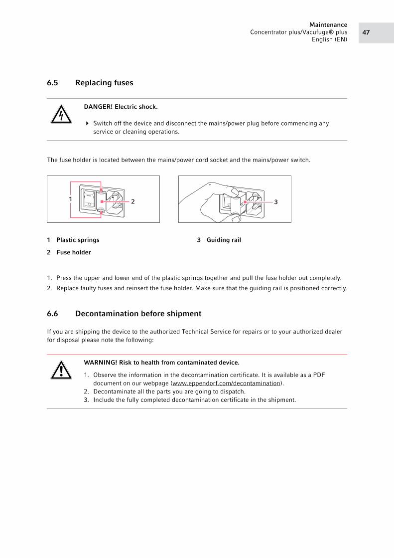
6.5 Replacing fuses
The fuse holder is located between the mains/power cord socket and the mains/power switch.
1. Press the upper and lower end of the plastic springs together and pull the fuse holder out completely.
2. Replace faulty fuses and reinsert the fuse holder. Make sure that the guiding rail is positioned correctly.
6.6 Decontamination before shipment
If you are shipping the device to the authorized Technical Service for repairs or to your authorized dealer
for disposal please note the following:
DANGER! Electric shock.
Switch off the device and disconnect the mains/power plug before commencing any
service or cleaning operations.
1 Plastic springs
2 Fuse holder
3 Guiding rail
WARNING! Risk to health from contaminated device.
1. Observe the information in the decontamination certificate. It is available as a PDF
document on our webpage (www.eppendorf.com/decontamination).
2. Decontaminate all the parts you are going to dispatch.
3. Include the fully completed decontamination certificate in the shipment.
1 2 3

MaintenanceConcentrator plus/Vacufuge® plus
English (EN)48
49Troubleshooting
Concentrator plus/Vacufuge® plus
English (EN)
7 Troubleshooting
If you cannot remedy an error with the recommended measures, please contact your local Eppendorf
partner. The contact address can be found on the Internet at www.eppendorf.com.
7.1 General errors
Problem Cause Solution
No display. No mains/power connection. Check the mains/power connection.
Mains/power outage. Check the fuse of the centrifuge.
Check the mains/power fuse of the
lab.
Centrifuge lid
cannot be opened.
The rotor is still running. Wait for the rotor to stop.
Mains/power outage. 1. Check the fuse of the centrifuge.
2. Check the mains/power fuse of the
lab.
3. Activate the emergency lid release.
Centrifuge cannot
be started.
The centrifuge lid is not closed. Close the centrifuge lid.
Centrifuge shakes
when it starts up.
The rotor is loaded asymmetrically. 1. Stop the centrifuge and load
symmetrically.
2. Restart the centrifuge.
No noticeable
evaporation.
Damaged sealing ring in the lid of the
device.
Insert new sealing ring(see Others
accessories on p. 64).
Pump does not start
up.
Pump is overloaded.
Thermo switch in the motor winding of
the pump triggered.
Let the pump cool down.
Pump does not start
up.
Overpressure in the exhaust gas line. Open the exhaust gas line.
No output. Long, thin hoses. Select short hoses with a large
cross-section.
No output. Condensation in the pump. Let pump run for a few minutes and
press the mode/vent key several
times.
Temperature value
flashes.
Deviation from set value by ± 5 °C. Let the remaining heat from the
previous run cool down.
Reduce the excessive ambient
temperature, if applicable.
Temperature value
flashes fast.
Deviation from set value by + 10 °C. Switch off external heat sources (e.g.,
halogen lamp).
Liquid collects in
the hoses.
Activate the ventilation function.
Check the fall of the hoses.
TroubleshootingConcentrator plus/Vacufuge® plus
English (EN)50
7.2 Error messages
If one of the following error messages appears, proceed as follows:
1. Remove fault (see Remedy).
2. Press the start/stop key to clear the error message.
3. If required, continue concentration and/or repeat.
Problem Cause Solution
Error 1 Drive fault Contact Service.
Error 2
Error 3
Error 4
Drive blocked or stiff. Move the rotor by hand, remove any
obstructions.
Check the max. load of rotor.
Check the rotor mounting.
Error 5 Drive fault Contact Service.
Error 7 Error in the lid latch. Contact Service.
Error 8 Fault at the temperature sensor Contact Service.
Error 9 Electronics fault. Caution! The rotor chamber
temperature may be > 72°C.
Contact Service.
Error 10 Heater defective. Contact Service.
Error 12
Error 14
Error 16
Electronics fault. Contact Service.
IMBAL The rotor is loaded asymmetrically. Load the rotor symmetrically and
balance it.
51Troubleshooting
Concentrator plus/Vacufuge® plus
English (EN)
7.3 Opening the device in case of a mains/power outage using the emergency release
If the device lid cannot be opened during a mains/power outage, you can activate the emergency release
manually.
1. Disconnect the mains/power plug.
2. Insert a wire (max. 2.5 mm thick, e.g., a paper clip) into the opening on the right-hand side of the
housing and push against the noticeable resistance.
This will release the device lid.
3. Open the device lid slightly.
4. Remove the wire.
5. Open the device lid fully.
WARNING! Risk of injury from rotating rotor.If the emergency release of the lid is activated, the rotor may continue to rotate for several
minutes.
Wait for the rotor to stop before activating the emergency release.
To check, look through the monitoring glass in the centrifuge lid.
If there is a mains/power outage, the vent valve will open. Before the rotor comes to a
standstill, the standard pressure in the rotor chamber will be restored.

TroubleshootingConcentrator plus/Vacufuge® plus
English (EN)52
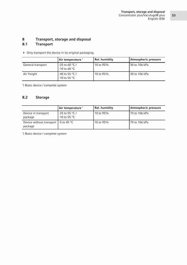
53Transport, storage and disposal
Concentrator plus/Vacufuge® plus
English (EN)
8 Transport, storage and disposal8.1 Transport
Only transport the device in its original packaging.
*) Basic device / complete system
8.2 Storage
*) Basic device / complete system
Air temperature * Rel. humidity Atmospheric pressure
General transport -25 to 60 °C /
-10 to 60 °C
10 to 95% 30 to 106 kPa
Air freight -40 to 55 °C /
-10 to 55 °C
10 to 95% 30 to 106 kPa
Air temperature * Rel. humidity Atmospheric pressure
Device in transport
package
-25 to 55 °C /
-10 to 55 °C
10 to 95% 70 to 106 kPa
Device without transport
package
-5 to 45 °C 10 to 95% 70 to 106 kPa
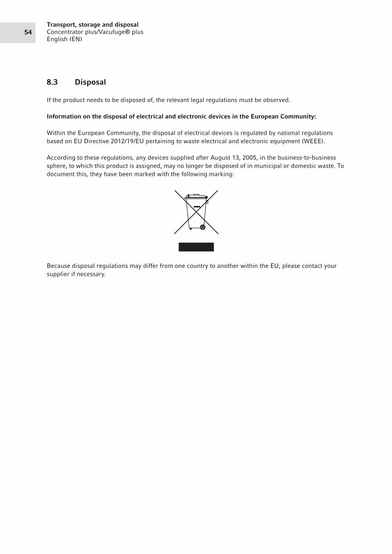
Transport, storage and disposalConcentrator plus/Vacufuge® plus
English (EN)54
8.3 Disposal
If the product needs to be disposed of, the relevant legal regulations must be observed.
Information on the disposal of electrical and electronic devices in the European Community:
Within the European Community, the disposal of electrical devices is regulated by national regulations
based on EU Directive 2012/19/EU pertaining to waste electrical and electronic equipment (WEEE).
According to these regulations, any devices supplied after August 13, 2005, in the business-to-business
sphere, to which this product is assigned, may no longer be disposed of in municipal or domestic waste. To
document this, they have been marked with the following marking:
Because disposal regulations may differ from one country to another within the EU, please contact your
supplier if necessary.

55Technical data
Concentrator plus/Vacufuge® plus
English (EN)
9 Technical data9.1 Power supply
9.2 Ambient conditions
9.3 Weight/dimensions
5305 Basic device 5305 Complete system
Mains/power connection 230 V, 50 – 60 Hz
120 V, 50 – 60 Hz
100 V, 50 – 60 Hz
230 V, 50 – 60 Hz
120 V, 50 – 60 Hz
100 V, 50 – 60 Hz
Current consumption 2.1 A (230 V)
6.0 A (120 V)
5.2 A (100 V)
1.7 A (230 V)
5.6 A (120 V)
3.8 A (100 V)
Power consumption max. 500 W (230 V)
max. 550 W (120 V)
max. 520 W (100 V)
max. 350 W (230 V)
max. 400 W (120 V)
max. 380 W (100 V)
EMC: Noise emission (radio
interference)
100 V: EN 61326-1/EN 55011 – Class B
120 V: CFR 47 FCC Part 15 – Class B
230 V: EN 61326-1/EN 55011 – Class B
EMC: Noise immunity EN 61326-1- basic electromagnetic environment
Overvoltage category II
Fuses 230 V > 250 V 4AT HBC
100/120 V > 250 V 6.3AT HBC
Degree of pollution 2
Environment: For indoor use only.
Ambient temperature: 15 to 35 °C
Max. relative humidity: 75 %, non-condensing humidity
Atmospheric pressure: 79.5 kPa – 106 kPa
5305 Basic device 5305 Complete system with connection for external device
Dimensions: Width: 330 mm (12.6 in.)
Depth: 372 mm (14.5 in.)
Height: 231 mm (9.1 in.)
Width: 330 mm (12.6 in.)
Depth: 579 mm (20.9 in.)
Height: 290 mm (11.7 in.)
Weight without rotor: 16.5 kg (37.5 lb.) 31.5 kg (68.3 lb.)
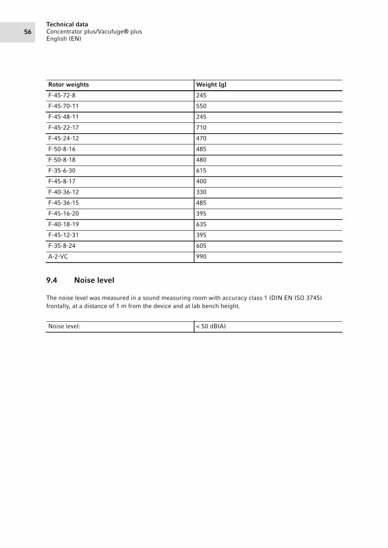
Technical dataConcentrator plus/Vacufuge® plus
English (EN)56
9.4 Noise level
The noise level was measured in a sound measuring room with accuracy class 1 (DIN EN ISO 3745)
frontally, at a distance of 1 m from the device and at lab bench height.
Rotor weights Weight [g]
F-45-72-8 245
F-45-70-11 550
F-45-48-11 245
F-45-22-17 710
F-45-24-12 470
F-50-8-16 485
F-50-8-18 480
F-35-6-30 615
F-45-8-17 400
F-40-36-12 330
F-45-36-15 485
F-45-16-20 395
F-40-18-19 635
F-45-12-31 395
F-35-8-24 605
A-2-VC 990
Noise level: < 50 dB(A)
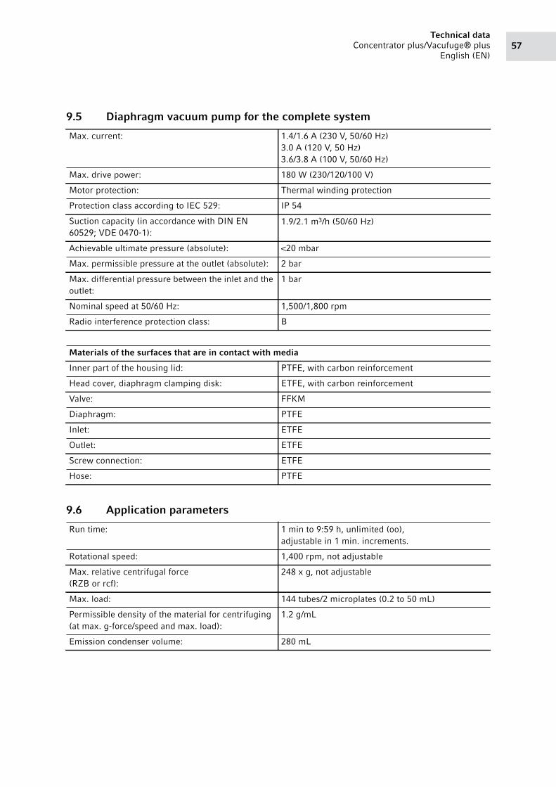
57Technical data
Concentrator plus/Vacufuge® plus
English (EN)
9.5 Diaphragm vacuum pump for the complete system
9.6 Application parameters
Max. current: 1.4/1.6 A (230 V, 50/60 Hz)
3.0 A (120 V, 50 Hz)
3.6/3.8 A (100 V, 50/60 Hz)
Max. drive power: 180 W (230/120/100 V)
Motor protection: Thermal winding protection
Protection class according to IEC 529: IP 54
Suction capacity (in accordance with DIN EN
60529; VDE 0470-1):
1.9/2.1 m3/h (50/60 Hz)
Achievable ultimate pressure (absolute): <20 mbar
Max. permissible pressure at the outlet (absolute): 2 bar
Max. differential pressure between the inlet and the
outlet:
1 bar
Nominal speed at 50/60 Hz: 1,500/1,800 rpm
Radio interference protection class: B
Materials of the surfaces that are in contact with media
Inner part of the housing lid: PTFE, with carbon reinforcement
Head cover, diaphragm clamping disk: ETFE, with carbon reinforcement
Valve: FFKM
Diaphragm: PTFE
Inlet: ETFE
Outlet: ETFE
Screw connection: ETFE
Hose: PTFE
Run time: 1 min to 9:59 h, unlimited (oo),
adjustable in 1 min. increments.
Rotational speed: 1,400 rpm, not adjustable
Max. relative centrifugal force
(RZB or rcf):
248 x g, not adjustable
Max. load: 144 tubes/2 microplates (0.2 to 50 mL)
Permissible density of the material for centrifuging
(at max. g-force/speed and max. load):
1.2 g/mL
Emission condenser volume: 280 mL
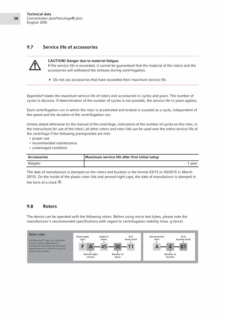
Technical dataConcentrator plus/Vacufuge® plus
English (EN)58
9.7 Service life of accessories
Eppendorf states the maximum service life of rotors and accessories in cycles and years. The number of
cycles is decisive. If determination of the number of cycles is not possible, the service life in years applies.
Each centrifugation run in which the rotor is accelerated and braked is counted as a cycle, independent of
the speed and the duration of the centrifugation run.
Unless stated otherwise (in the manual of the centrifuge, indications of the number of cycles on the rotor, in
the instructions for use of the rotor), all other rotors and rotor lids can be used over the entire service life of
the centrifuge if the following prerequisites are met:
• proper use
• recommended maintenance
• undamaged condition
The date of manufacture is stamped on the rotors and buckets in the format 03/15 or 03/2015 (= March
2015). On the inside of the plastic rotor lids and aerosol-tight caps, the date of manufacture is stamped in
the form of a clock .
9.8 Rotors
The device can be operated with the following rotors. Before using micro test tubes, please note the
manufacturer's recommended specifications with regard to centrifugation stability (max. g-force).
CAUTION! Danger due to material fatigue.If the service life is exceeded, it cannot be guaranteed that the material of the rotors and the
accessories will withstand the stresses during centrifugation.
Do not use accessories that have exceeded their maximum service life.
Accessories Maximum service life after first initial setup
Adapter 1 year
Rotor code:
All Eppendorf® rotors are identified
using a simple, alphanumeric
format that represents the technical
specifications in a uniform series of
letters and numbers.
A 45 30 11Aerosol-tight
version
F
Fixed-anglerotor
Angle ofbores
Ø ofbores (mm)
Number ofbores
A
Swing-bucketrotor
4 81
Ø ofbuckets (mm)
Number ofbuckets
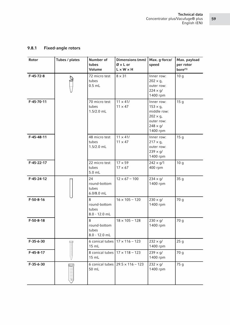
59Technical data
Concentrator plus/Vacufuge® plus
English (EN)
9.8.1 Fixed-angle rotors
Rotor Tubes / plates Number of tubesVolume
Dimensions (mm) Ø × L or L × W × H
Max. g-force/speed
Max. payload per rotor bore(1)
F-45-72-8 72 micro test
tubes
0.5 mL
8 × 31 Inner row:
202 × g,
outer row:
224 × g/
1 400 rpm
10 g
F-45-70-11 70 micro test
tubes
1.5/2.0 mL
11 × 41/
11 × 47
Inner row:
153 × g,
middle row:
202 × g,
outer row:
248 × g/
1 400 rpm
15 g
F-45-48-11 48 micro test
tubes
1.5/2.0 mL
11 × 41/
11 × 47
Inner row:
217 × g,
outer row:
239 × g/
1 400 rpm
15 g
F-45-22-17 22 micro test
tubes
5.0 mL
17 × 59
17 × 67
242 × g/1
400 rpm
10 g
F-45-24-12 24
round-bottom
tubes
6.0/8.0 mL
12 × 67 – 100 234 × g/
1 400 rpm
35 g
F-50-8-16 8
round-bottom
tubes
8.0 - 12.0 mL
16 × 105 – 120 230 × g/
1 400 rpm
70 g
F-50-8-18 8
round-bottom
tubes
8.0 - 12.0 mL
18 × 105 – 128 230 × g/
1 400 rpm
70 g
F-35-6-30 6 conical tubes
15 mL
17 × 116 – 123 232 × g/
1 400 rpm
25 g
F-45-8-17 8 conical tubes
15 mL
17 × 118 – 123 239 × g/
1 400 rpm
70 g
F-35-6-30 6 conical tubes
50 mL
29.5 × 116 – 123 232 × g/
1 400 rpm
75 g
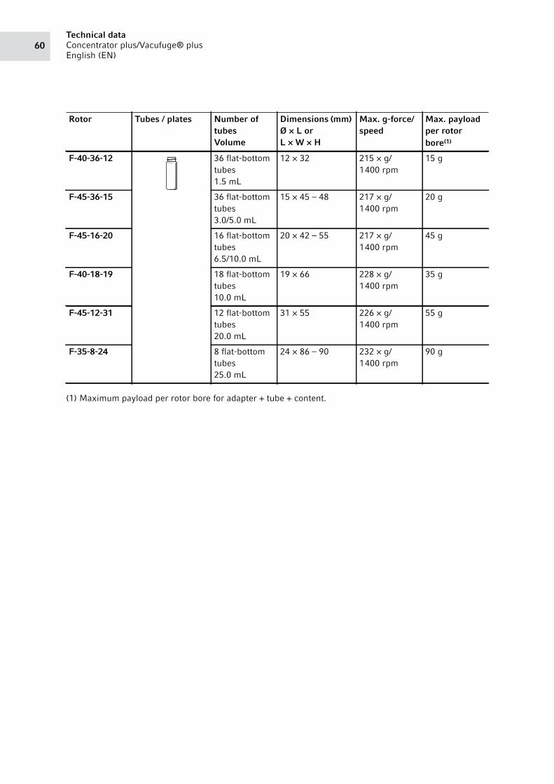
Technical dataConcentrator plus/Vacufuge® plus
English (EN)60
(1) Maximum payload per rotor bore for adapter + tube + content.
F-40-36-12 36 flat-bottom
tubes
1.5 mL
12 × 32 215 × g/
1 400 rpm
15 g
F-45-36-15 36 flat-bottom
tubes
3.0/5.0 mL
15 × 45 – 48 217 × g/
1 400 rpm
20 g
F-45-16-20 16 flat-bottom
tubes
6.5/10.0 mL
20 × 42 – 55 217 × g/
1 400 rpm
45 g
F-40-18-19 18 flat-bottom
tubes
10.0 mL
19 × 66 228 × g/
1 400 rpm
35 g
F-45-12-31 12 flat-bottom
tubes
20.0 mL
31 × 55 226 × g/
1 400 rpm
55 g
F-35-8-24 8 flat-bottom
tubes
25.0 mL
24 × 86 – 90 232 × g/
1 400 rpm
90 g
Rotor Tubes / plates Number of tubesVolume
Dimensions (mm) Ø × L or L × W × H
Max. g-force/speed
Max. payload per rotor bore(1)
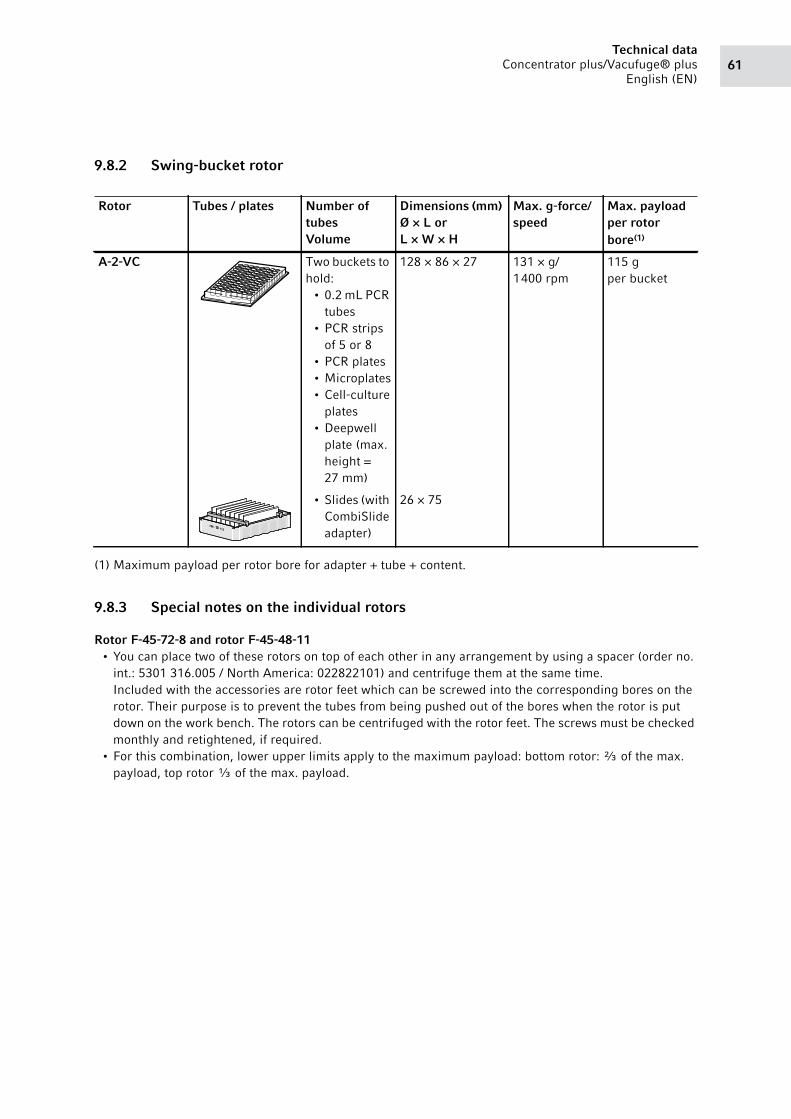
61Technical data
Concentrator plus/Vacufuge® plus
English (EN)
9.8.2 Swing-bucket rotor
(1) Maximum payload per rotor bore for adapter + tube + content.
9.8.3 Special notes on the individual rotors
Rotor F-45-72-8 and rotor F-45-48-11• You can place two of these rotors on top of each other in any arrangement by using a spacer (order no.
int.: 5301 316.005 / North America: 022822101) and centrifuge them at the same time.
Included with the accessories are rotor feet which can be screwed into the corresponding bores on the
rotor. Their purpose is to prevent the tubes from being pushed out of the bores when the rotor is put
down on the work bench. The rotors can be centrifuged with the rotor feet. The screws must be checked
monthly and retightened, if required.
• For this combination, lower upper limits apply to the maximum payload: bottom rotor: ⅔ of the max.
payload, top rotor ⅓ of the max. payload.
Rotor Tubes / plates Number of tubesVolume
Dimensions (mm) Ø × L or L × W × H
Max. g-force/speed
Max. payload per rotor bore(1)
A-2-VC Two buckets to
hold:
• 0.2 mL PCR
tubes
• PCR strips
of 5 or 8
• PCR plates
• Microplates
• Cell-culture
plates
• Deepwell
plate (max.
height =
27 mm)
128 × 86 × 27 131 × g/
1 400 rpm
115 g
per bucket
• Slides (with
CombiSlide
adapter)
26 × 75
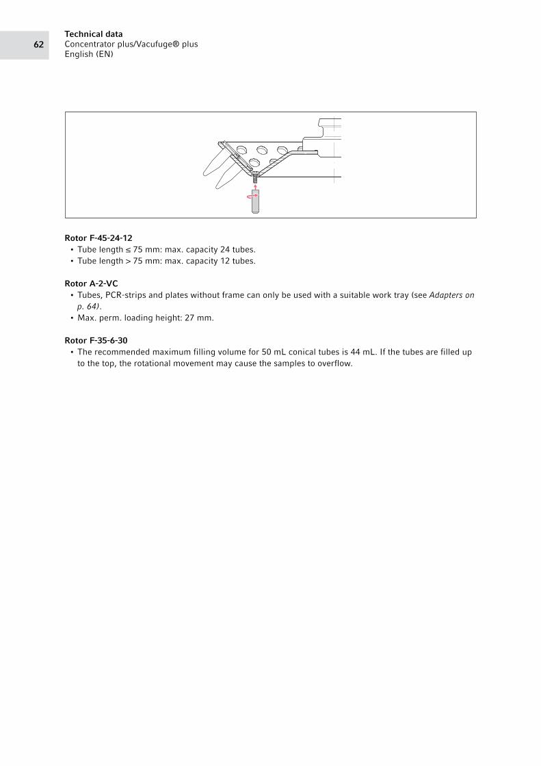
Technical dataConcentrator plus/Vacufuge® plus
English (EN)62
Rotor F-45-24-12• Tube length ≤ 75 mm: max. capacity 24 tubes.
• Tube length > 75 mm: max. capacity 12 tubes.
Rotor A-2-VC• Tubes, PCR-strips and plates without frame can only be used with a suitable work tray (see Adapters on
p. 64).
• Max. perm. loading height: 27 mm.
Rotor F-35-6-30• The recommended maximum filling volume for 50 mL conical tubes is 44 mL. If the tubes are filled up
to the top, the rotational movement may cause the samples to overflow.
63Ordering information
Concentrator plus/Vacufuge® plus
English (EN)
10 Ordering information10.1 Fuses
10.2 Accessories10.2.1 Rotors
Order no. (International)
Order no. (North America)
Description
Fuse5301 850.249 022654403 4.0 A T (230 V), 2 pieces
5417 341.007 022375831 6,3 A T (230 V), 2 pieces
Order no. (International)
Order no. (North America)
Description
Rotor F-45-72-85490 034.007 022822080 72 positions for 0.5 mL tubes
Rotor F-45-70-115490 032.004 022822047 70 positions for 1.5/2.0 mL tubes
Rotor F-45-48-115490 030.001 022822004 48 positions for 1.5/2.0 mL tubes
Rotor F-45-24-125490 036.000 022822144 24 positions for 6.0/8.0 mL round-bottom tubes (12 ×
67-100 mm)
Rotor F-50-8-165490 041.003 022822233 8 positions for 15.0/20.0 mL round-bottom tubes (16 ×
105-120 mm)
Rotor F-50-8-185490 042.000 022822179 8 positions for 15.0/20.0 mL round-bottom tubes (18 ×
105-128 mm)
Rotor F-45-8-175490 038.002 022822225 8 positions for 15 mL conical tubes (17 × 118-123 mm)
Rotor F-40-36-125490 040.007 022822209 36 positions for 1.5 mL flat-bottom tubes (12 × 32 mm)
Rotor F-45-36-155490 035.003 022822128 36 positions for 3.0/5.0 mL flat-bottom tubes (15 × 48 mm)
Rotor F-45-16-205490 043.006 022822136 16 positions for 6.5/10.0 mL flat-bottom tubes (20 ×
42-55 mm)
Rotor F-40-18-195490 037.006 022822161 18 positions for 10.0 mL flat-bottom tubes (19 × 66 mm)
Rotor F-45-12-315490 044.002 022822217 12 positions for 20.0 mL flat-bottom tubes (31 × 55 mm)
Rotor F-35-8-245490 039.009 022822187 8 positions for 25.0 mL flat-bottom tubes (24 × 86-90 mm)
Rotor F-35-6-305490 047.001 022822231 6 positions for 15 mL conical tubes (17 × 116-123 mm) and
50 mL conical tubes (29.5 × 116-123 mm)
Rotor A-2-VC5490 045.009 022822241 incl. 2 buckets
Ordering informationConcentrator plus/Vacufuge® plus
English (EN)64
10.2.2 Adapters
10.2.3 Others accessories
Rotor F-45-22-175490 048.008 5490048008 22 × 5-mL conical tubes (16 × 60 mm)
Order no. (International)
Order no. (North America)
Description
Work trayfor semi-/unskirted PCR plates, PCR strips and
0.2 mL PCR tubes, for Rotor A-2-VC
0030 124.235 951010031 set of 10 pcs.
Frame for work trayfor Rotor A-2-VC
0030 124.243 951010049 set of 5 pcs.
Adapterused in A-2-VC
5825 706.005 022638963 CombiSlide Adapter, set of 2
Adapterused in F-45-48-11 and F-45-70-11
5425 715.005 022636260 for 1 PCR tube (0.2 mL, max. Ø 6 mm), set of 6
5425 717.008 022636243 for 1 micro test tube (0.4 mL, max. Ø 6 mm), set of 6
5425 716.001 022636227 for 1 sample tube (0.5 mL, max. Ø 6 mm) or 1 Microtainer
(0.6 mL, max. Ø 8 mm), set of 6
Order no. (International)
Order no. (North America)
Description
Spacer for simultaneous operation of two rotors5301 316.005 022822101 for F-45-72-8 and F-45-48-11
Special plug for external vacuum pump < 400 W5301 010.003 - 230 V (Germany), different options upon request
5301 033.003 022830110 120 V, different options upon request
Solenoid valve for external vacuum pumpOnly suitable for aqueous and alcoholic solvents.
5301 030.004 022830104 230 V, 50 – 60 Hz
5301 036.002 022830112 120 V
Rotor feet for F-45-72-8 and F-45-48-115490 030.800 022830520 Set of 3
Order no. (International)
Order no. (North America)
Description

Certificates

Evaluate Your Manual
Give us your feedback.
www.eppendorf.com/manualfeedback
Your local distributor: www.eppendorf.com/contactEppendorf AG · Barkhausenweg 1 · 22339 Hamburg · Germany
[email protected] · www.eppendorf.com