comprehensive rock engineering - stmr
TRANSCRIPT
COMPREHENSIVE ROCK ENGINEERING
Principles, Practice & Projects
Editor-in-Chief
JOHN A. HUDSON Imperial College of Science, Technology & Medicine, London, UK
Volume 3
ROCK TESTING AND SITE CHARACTERIZATION
Volume Editor
JOHN A. HUDSON Imperial College of Science, Technology & Medicine, London, UK
A Geomechanical Classification for Slopes:
Slope Mass Rating
M. R. ROMANA Universidad Politécnica Valencia, Spain
PERGAMON PRESS
OXFORD – NEW YORK SEOUL TOKYO

Pergamon Press Ltd, Headington Hill Hall, Oxford, OX3 0BW, England Pergamon Press Inc., 660 White Plains Road, Tarrytown New York 10591-5153, USA Pergamon Press Korea, KPO Box 315, Seoul 110-603, Korea Pergamon press Japan, Tsunashima Building Annex, 3-20-12 Yushima, Bunkyo-ku, Tokyo 113, Japan
Copyright © 1993 Pergamon Press Ltd
All rights reserved. No part of this publication may be reproduced, Stored in any retrieval system or transmitted in any form or by any Means: electronic, electrostatic, magnetic tape, mechanical, photo- copying, recording or otherwise, without permission in writing from the publishers.
First edition 1993
Library of Congress Cataloguing in Publication Data
Comprehensive rock engineering: principles, practice, and projects/
editor-in-chief, John A. Hudson. – 1st ed. p. cm.
Includes indexes. ISBN 0-08-035931-0 (HC) L Rock mechanics. L Hudson, J.A. (John, A.)
TA706.C642 1993 6241’5132-dc200 92-18616
British Library Cataloguing in Publication Data
A catalogue record for this book is available from the British
Library.
ISBN 0-08-042066-4 (Vol. 3)
ISBN 0-08-035931-0 (Set)
© ™ The paper used in this publication meets the minimum requirements of the American national Standard for Information Sciences Permanence of paper for Printed Library materials, ANSI Z39.48-1984 Printer in Great Britain by BPCC Wheatons Ltd, Exeter

A Geomechanical Classification for Slopes: Slope Mass Rating MANUEL R. ROMANA Universidad Politécnica Valencia, Spain
INTODUCTION...........................................................................................................................................4 1. RMR CONCEPT..........................................................................................................................4
1.1 DEVELOPMENT OF RMR ........................................................................................4 1.2 PREVIOUS APPLICATION OF RMR TO SLOPES ...............................................5
2. FAILURE MODES IN SLOPES.................................................................................................7 3. SLOPE MASS RATING (SMR)..................................................................................................9 4. GUIDELINES FOR SMR EVALUATION ..............................................................................14
4.1 CHOOSING THE OUTCROPS ................................................................................14 4.2 STRENGTH OF INTACT ROCK.............................................................................15 4.3 RQD .............................................................................................................................16 4.4 JOINT SPACING (SI) ................................................................................................18 4.5 JOINT CONDITION..................................................................................................18
4.5.1. Roughness / filling .......................................................................................18 4.5.2. Separation ....................................................................................................19 4.5.3. Persistence....................................................................................................20 4.5.4. Weathering of walls.....................................................................................20 4.5.5. Parametric rating ........................................................................................20
4.6 GROUNDWATER......................................................................................................21 4.7 ORIENTATIONS .......................................................................................................23
4.7.1. Joints.............................................................................................................23 4.7.2. Slope .............................................................................................................23
4.8 BLASTING METHODS.............................................................................................24 5. CASE RECORDS.......................................................................................................................25 6. STABILITY CLASSES..............................................................................................................28 7. SUPPORT MEASURES ............................................................................................................30
7.1 GENERAL...................................................................................................................30 7.2 PROTECTION MEASURES.....................................................................................34
7.2.1. Toe ditch.......................................................................................................34 7.2.2. Nets ...............................................................................................................35
7.3 REINFORCEMENT...................................................................................................36 7.3.1. Bolting ..........................................................................................................36 7.3.2. Anchoring.....................................................................................................37
7.4 CONCRETING...........................................................................................................40 7.4.1. Shotcrete.......................................................................................................40 7.4.2. Dental concrete ............................................................................................40 7.4.3. Ribs, beams and walls .................................................................................41
7.5 DRAINAGE.................................................................................................................42 7.5.1. Surface drainage..........................................................................................42 7.5.2. Deep drainage ..............................................................................................42
8. CONCLUSIONS.........................................................................................................................44 9. REFERENCES ...........................................................................................................................44
INTODUCTION
This chapter presents a new geomechanical classification for slopes in rock, the ‘Slope Mass Rating’
(SMR). SMR can be very useful as a tool for the preliminary assessment of slope stability. It gives some simple
rules about instability modes and the required support measures. It cannot be a substitute for detailed analysis of
each slope, which must combine both good commonsense engineering and sound analytical methods.
SMR classification is a development of the Bieniawski ‘Rock Mass Rating’ (RMR) system which has
become known worldwide, and applied by many technicians as a systematic tool to describe rock mass
conditions. The RMR concept has been proven to be particularly useful in assessing the need for support in tunnel
studies.
Application of the RMR system to slopes has not been possible to date. The SMR system provides
adjustment factors, field guidelines and recommendations on support methods which allow a systematic use of
geomechanical classification for slopes. Bieniawski [1] has included an abridged version of SMR in his latest
book on rock classification.
1. RMR CONCEPT
1.1 DEVELOPMENT OF RMR
ln 1973 Bieniawski [2] introduced ‘Rock Mass Rating’ (RMR), a new system of rock mass classification,
also known as CSIR classification. It included eight rock ‘parameters’, one of which was ‘strike and dip
orientations of joints’. Emphasis was given to the use of RMR classification in tunnels.
In the second version of RMR classification [3] some major changes were introduced. Five rock mass
parameters were added to obtain the numerical RMR value. From this RMR value, a ‘rating adjustment for
discontinuity orientations’ (always a negative number) was subtracted. Some minor modifications were made in
1979 [4], and the actual form of RMR rating was established (see Table 1).
Bieniawski and Orr [5] applied RMR to dam foundations, correlating the RMR value to the in situ
modulus of deformation. Serafim and Pereira [6] completed this correlation. Kendorski et al. [7] developed a new
classification ‘Modified Basic RMR’ (BMR) for mining with caving methods. Several new parameters were
included—blasting damage, induced stress, major geological structures, distance to cave-line and block panel
size.

1.2 PREVIOUS APPLICATION OF RMR TO SLOPES
In the 1976 version, the ‘rating adjustments for discontinuity orientation< for slopes were
very favorable O
favorable — 5
fair — 25
unfavorable — 50
very unfavorable — 60
No guidelines have been published for the definition of each class. ln the same Symposium Steffen [8]
stated that 635 slopes, of which 20 have failed, were classified, and the average values of cohesion and friction
were used (to obtain) factors of safety with Hoek design charts for circular failure. Figure 1 shows Steffen’s
results, with ‘a definite statistical trend’. It was concluded that ‘the scope for using classification alone as a design
method is still very limited’. No reference is given by Bieniawski [9] in 1984 for the use of the RMR
classification in slopes. The reason for this lack of use is probably the extremely high values of the ‘adjustment
rating value’, which can reach 60 points out of 100. A mistake in this value can supersede by far any careful
evaluation of the rock rnass, and classification work would be both difficult and arbitrary.
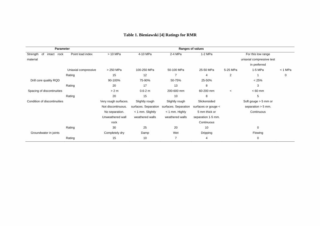
Table 1. Bieniawski [4] Ratings for RMR
Parameter Ranges of values
Strength of intact rock
material
Point load index > 10 MPa 4-10 MPa 2-4 MPa 1-2 MPa For this low range
uniaxial compressive test
in preferred
Uniaxial compressive > 250 MPa 100-250 MPa 50-100 MPa 25-50 MPa 5-25 MPa 1-5 MPa < 1 MPa
Rating 15 12 7 4 2 1 0
Drill core quality RQD 90-100% 75-90% 50-75% 25-50% < 25%
Rating 20 17 13 8 3
Spacing of discontinuities > 2 m 0.6-2 m 200-600 mm 60-200 mm < < 60 mm
Rating 20 15 10 8 5
Condition of discontinuities Very rough surfaces.
Not discontinuous.
No separation.
Unweathered wall
rock
Slightly rough
surfaces. Separation
< 1 mm. Slightly
weathered walls
Slightly rough
surfaces. Separation
< 1 mm. Highly
weathered walls
Slickensided
surfaces or gouge <
5 mm thick or
separation 1-5 mm.
Continuous
Soft gouge > 5 mm or
separation > 5 mm.
Continuous
Rating 30 25 20 10 0
Groundwater in joints Completely dry Damp Wet Dripping Flowing
Rating 15 10 7 4 0
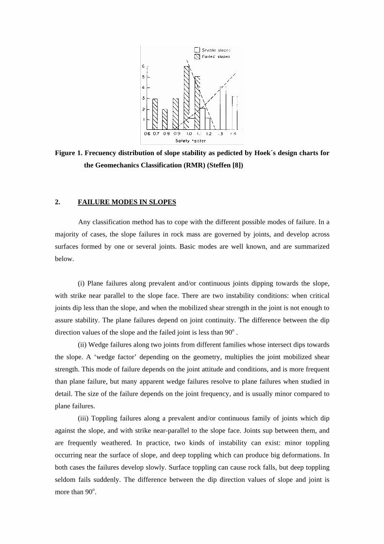
Figure 1. Frecuency distribution of slope stability as pedicted by Hoek´s design charts for
the Geomechanics Classification (RMR) (Steffen [8])
2. FAILURE MODES IN SLOPES
Any classification method has to cope with the different possible modes of failure. In a
majority of cases, the slope failures in rock mass are governed by joints, and develop across
surfaces formed by one or several joints. Basic modes are well known, and are summarized
below.
(i) Plane failures along prevalent and/or continuous joints dipping towards the slope,
with strike near parallel to the slope face. There are two instability conditions: when critical
joints dip less than the slope, and when the mobilized shear strength in the joint is not enough to
assure stability. The plane failures depend on joint continuity. The difference between the dip
direction values of the slope and the failed joint is less than 90o .
(ii) Wedge failures along two joints from different families whose intersect dips towards
the slope. A ‘wedge factor’ depending on the geometry, multiplies the joint mobilized shear
strength. This mode of failure depends on the joint attitude and conditions, and is more frequent
than plane failure, but many apparent wedge failures resolve to plane failures when studied in
detail. The size of the failure depends on the joint frequency, and is usually minor compared to
plane failures.
(iii) Toppling failures along a prevalent and/or continuous family of joints which dip
against the slope, and with strike near-parallel to the slope face. Joints sup between them, and
are frequently weathered. In practice, two kinds of instability can exist: minor toppling
occurring near the surface of slope, and deep toppling which can produce big deformations. In
both cases the failures develop slowly. Surface toppling can cause rock falls, but deep toppling
seldom fails suddenly. The difference between the dip direction values of slope and joint is
more than 90o.

(iv) Soil-type failure along a surface which only partially develops along joints, but
mainly crosses them. These failures can only happen in heavily jointed rock masses with a very
small block-type size and/or very weak or heavily weathered rock. In both cases, the RMR
value is very low, and the material is borderline with a soil.
Any classification system has to take account of the following ‘parameters’.
(i) Rock mass global characterization (including joints frequency, state and water
inflow). (ii) Differences in strike between slope face and prevalent joints.
(iii) Differences between joint dip angle and slope dip angle, as they control the
‘daylighting’ of a joint in the slope face, a necessary condition for plane and/or
wedge failure.
(iv) Relationship of joint dip angle with normal values of joint friction (for plane
and/or wedge failure).
(v) Relationships of tangential stresses, developed along a joint, with friction (for
toppling failure).
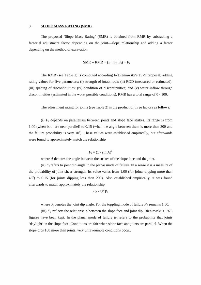
3. SLOPE MASS RATING (SMR)
The proposed ‘Slope Mass Rating’ (SMR) is obtained from RMR by subtracting a
factorial adjustment factor depending on the joint—slope relationship and adding a factor
depending on the method of excavation
SMR = RMR + (F1 . F2 . F3) + F4
The RMR (see Table 1) is computed according to Bieniawski’s 1979 proposal, adding
rating values for five parameters: (i) strength of intact rock; (ii) RQD (measured or estimated);
(iii) spacing of discontinuities; (iv) condition of discontinuities; and (v) water inflow through
discontinuities (estimated in the worst possible conditions). RMR has a total range of 0 - 100.
The adjustment rating for joints (see Table 2) is the product of three factors as follows:
(i) F1 depends on parallelism between joints and slope face strikes. Its range is from
1.00 (when both are near parallel) to 0.15 (when the angle between them is more than 300 and
the failure probability is very 10o). These values were established empirically, but afterwards
were found to approximately match the relationship
F1 = (1 - sin A)2
where A denotes the angle between the strikes of the slope face and the joint.
(ii) F2 refers to joint dip angle in the planar mode of failure. In a sense it is a measure of
the probability of joint shear strength. Its value vanes from 1.00 (for joints dipping more than
45o) to 0.15 (for joints dipping less than 200). Also established empirically, it was found
afterwards to match approximately the relationship
F2 - tg2 βj
where βj denotes the joint dip angle. For the toppling mode of failure F2 remains 1.00.
(iii) F3 reflects the relationship between the slope face and joint dip. Bieniawski’s 1976
figures have been kept. In the planar mode of failure E3 refers to the probability that joints
‘daylight’ in the slope face. Conditions are fair when slope face and joints are parallel. When the
slope dips 100 more than joints, very unfavourable conditions occur.
For the toppling mode of failure, unfavourable or very unfavourable conditions cannot
happen in view of the nature of toppling, as there are very few sudden failures and many toppled
slopes remain standing. The Goodman-Bray [10] condition has been used to evaluate toppling
probability, with the hypothesis that this failure is more frequent in weathered slopes and there
is a small reduction (around 50) of shear strength due to rotational friction, as proposed by
Goodman [11].
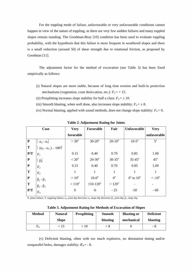
The adjustment factor for the method of excavation (see Table 3) has been fixed
empirically as follows:
(i) Natural slopes are more stable, because of long time erosion and built-in protection
mechanisms (vegetation, crust desiccation, etc.): F4 = + 15.
(ii) Presplitting increases slope stability for half a class: F4 = ± 10.
(iii) Smooth blasting, when well done, also increases slope stability: F4 = ± 8.
(iv) Normal blasting, applied with sound methods, does not change slope stability: F4 = 0.
Table 2. Adjustment Rating for Joints
Case Very
favorable
Favorable Fair Unfavorable Very
unfavorable
P
T
P/T
P
P
T
P
T
P/T
⏐αj - αs⏐
⏐(αj - αs ) – 180o⏐
F1
⏐βj⏐
F2
F2
βj - βs
βj - βs
F3
> 30o
0.15
< 20o
0.15
1
> 10o
< 110o
0
30-20o
0.40
20-30o
0.40
1
10-0o
110-120o
-6
20-10o
0.70
30-35o
0.70
1
0o
> 120o
- 25
10-5o
0.85
35-45o
0.85
1
0o to 10o
-
-50
5o
1.00
45o
1.00
1
< -10o
-
- 60
P, plane failure; T, toppling failure; αj, joint dip direction; αs slope dip direction; βj, joint dip; βs, slope dip
Table 3. Adjustment Rating for Methods of Excavation of Slopes
Method Natural
Slope
Presplitting Smooth
blasting
Blasting or
mechanical
Deficient
blasting
F4 + 15 + 10 + 8 0 - 8
(v) Deficient blasting, often with too much explosive, no detonation timing and/or
nonparallel boles, damages stability: F4 = - 8.
(vi) Mechanical excavation of slopes, usually by ripping, can be done only in soft
and/or very fractured rock, and is often combined with some preliminary blasting. The plane of
slope is difficult to finish. The method neither increases nor decreases slope stability: F4 = 0.
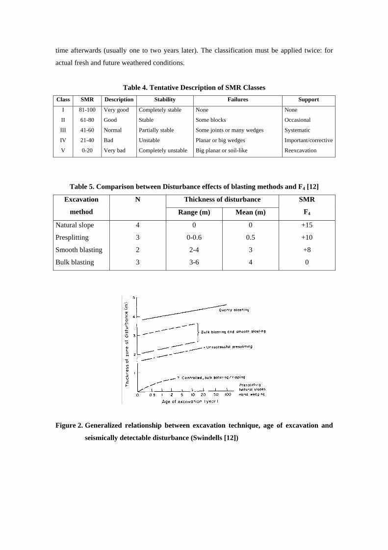
A tentative description of the SMR classes is given in Table 4.
Swindells [12] presented the results of an investigation on 16 different cuts, in five
locations in Scotland (natural slopes, railways, highways, quarries), to assess the influence of
blasting methods on slope stability. All the cuts were in igneous or metamorphic rocks. The cuts
were investigated with different techniques (visual inspection, field seismic refraction profiling,
borehole TV camera, and laboratory testing). Swindells concluded that ‘the degree of
measurable disturbance is related to excavation technique. Faces excavated by uncontrolled or
bulk blasting, or quarry blasting, exhibit greater thicknesses of measurable disturbances’. The
numerical data presented by Swindells have been reworked and compared with the SMR
corrective factor F4 in Table 5.
Figure 2 reproduces Swindells data and Figure 3 compares the depth of the disturbed
zone with the value of F4. There is a general similarity between the thickness of disturbed zone
and SMR F4 correction factor. The most important difference occurs with smooth blasting
techniques. The two cases investigated were registered by Swindells as ‘unsuccessful presplit’
and ‘bulk-smooth blasting’. Therefore it is possible that these data do not correspond to real,
successful excavations by smooth blasting methods.
Kendorski et al. [7] evaluated blasting damage in underground mines, by caving, with a
factor AB which multiplies RMR. Table 6 compares AB with the SMR corrective factor F4.
The final Slope Mass Rating is
SMR = RMR + (F1 .F2 . F3) + F4
No special factors taken for the wedge mode of failure are different from those applied
for the plane mode of failure. The practice of classification seems to prove that wedge failures
are no more dependent on RMR value than plane failures. Therefore, the classification must be
applied for each joints system. The minor value of SMR is retained for the slope.
Weathering cannot be assessed with rock mass classification as it is a temporal process
which depends mostly on the mineralogical conditions of rock and the climate. In certain
evolutive rocks (like some rnarls and clay-shales) the slopes are stable when open, and fail some
time afterwards (usually one to two years later). The classification must be applied twice: for
actual fresh and future weathered conditions.
Table 4. Tentative Description of SMR Classes Class SMR Description Stability Failures Support
I
II
III
IV
V
81-100
61-80
41-60
21-40
0-20
Very good
Good
Normal
Bad
Very bad
Completely stable
Stable
Partially stable
Unstable
Completely unstable
None
Some blocks
Some joints or many wedges
Planar or big wedges
Big planar or soil-like
None
Occasional
Systematic
Important/corrective
Reexcavation
Table 5. Comparison between Disturbance effects of blasting methods and F4 [12]
Thickness of disturbance Excavation
method
N
Range (m) Mean (m)
SMR
F4
Natural slope
Presplitting
Smooth blasting
Bulk blasting
4
3
2
3
0
0-0.6
2-4
3-6
0
0.5
3
4
+15
+10
+8
0
Figure 2. Generalized relationship between excavation technique, age of excavation and
seismically detectable disturbance (Swindells [12])
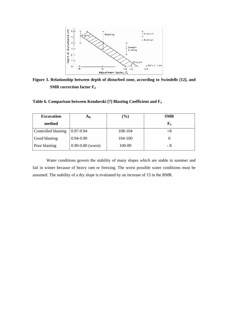
Figure 3. Relationship between depth of disturbed zone, according to Swindells [12], and
SMR correction factor F4
Table 6. Comparison between Kendorski [7] Blasting Coefficient and F4
Excavation
method
AB (%) SMR
F4
Controlled blasting
Good blasting
Poor blasting
0.97-0.94
0.94-0.90
0.90-0.80 (worst)
108-104
104-100
100-89
+8
0
- 8
Water conditions govern the stability of many slopes which are stable in summer and
fail in winter because of heavy ram or freezing. The worst possible water conditions must be
assumed. The stability of a dry slope is evaluated by an increase of 15 in the RMR.
4. GUIDELINES FOR SMR EVALUATION
4.1 CHOOSING THE OUTCROPS
Classification can be done on the following.
(i) Drillhole cores
Good for rock mass conditions.
Difficult for joints orientation.
Groundwater conditions can be assessed only from general groundwater levels.
(ii) Natural rock outcrops
Only the more sound rock outcrops so general conditions can be masked.
It is easy to measure joints orientation.
When comparing the failure modes the adjusting factor for ‘natural slope’ must be used.
(iii) Other slopes
The conditions of rock mass depend on slope age, excavation method and weathering
conditions. Joints can be more frequent and more open than in rock mass if deficient blasting
has been used. It is easy to forecast and compare the failure modes. It is easy to assess the water
conditions.
Each rock exposure has advantages and disadvantages. The best classification will be
done with a combination of natural outcrops and man-made slopes.
In order to cope with data variability it is necessary to individualize different structural
regions in the field for classification purposes. In each region the mean values will represent
only the mean conditions. But many slope failures happen in slopes which are stable in normal
conditions but which fail because some factor reached an extreme value. So classification
systems must take account of extreme conditions.
There are three common problems.
(i) Water conditions are much better during dry seasons, when most field work is
likely to be done. In cold climates ice can increase groundwater pressure.
(ii) Some materials show a different behavior at ‘long term’ because of weathering,
pore pressure redistribution, erosion or other causes. Time to failure can be one or
several years.
(iii) Frequently, failure is governed by a ‘special’ joint or set, which exhibits different
features and has a lower shear strength than ‘normal’ ones.
Classification cannot be a routine task done by people inexperienced in field work. A
form for field use is included at the end of this chapter. This form is better suited for
classification of existing natural or man-made slopes than for other outcrops.
4.2 STRENGTH OF INTACT ROCK
Adequate input data for the strength of intact rock is the uniaxial compressive strength
(C0) determined according to ¡SRM Suggested Methods or any other reliable testing standard.
However, often it is necessary lo assess strength in the field without the aid of laboratory tests.
Table 7 has been adapted from ¡SRM ‘Suggested Method for the Quantitative
Description of Discontinuities in Rock Masses’ [13] and can be helpful lo assess the uniaxial
compressive strength from manual index tests performed on rock specimens with a pocket knife
and/or geological hammer. Extremely strong rocks are very rare, and very strong rocks are not
common, so in most cases it is only necessary lo assess the strength of rock in the lower
categories, where the parameter values are low and the possible error not too big. Intact rock
strength can be tested in the field with the help of a ‘Schmidt Impact Hammer’ (also known as a
‘Sclerometer’).
Haramy and DeMarco [14] have summarized the procedures and results of several
authors, concluding that the test is ‘inexpensive, fast and reliable’ to obtain estimates of
compressive strength from core samples, most of them from NX gauge (55 mm diameter). They
mention correlations by Deere (1966) and Beverly (1979) between the Schmidt rebound index
(obtained when holding the hammer vertically downwards) and uniaxial compressive strength.
Testing procedures are described in ISRM ‘Suggested Method for Determining Hardness and
Abrasiveness of Rocks’ [15] and ‘Suggested Method for the Quantitative Description of
Discontinuities in Rock Masses’ [13]. They can be summarized as follows.
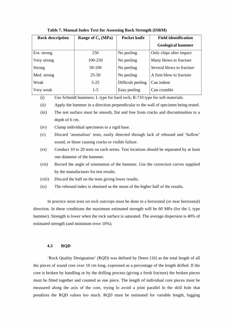
Table 7. Manual Index Text for Assessing Rock Strength (ISRM)
Rock description Range of Co (MPa) Pocket knife Field identification
Geological hammer
Ext. strong
Very strong
Strong
Med. strong
Weak
Very weak
250
100-250
50-100
25-50
5-25
1-5
No peeling
No peeling
No peeling
No peeling
Difficult peeling
Easy peeling
Only chips after impact
Many blows to fracture
Several blows to fracture
A firm blow to fracture
Can indent
Can crumble
(i) Use Schmidt hammers: L type for hard rock; R-710 type for soft materials.
(ii) Apply the hammer in a direction perpendicular to the wall of specimen being tested.
(iii) The test surface must be smooth, flat and free from cracks and discontinuities to a
depth of 6 cm.
(iv) Clamp individual specimens to a rigid base.
(v) Discard ‘anomalous’ tests, easily detected through lack of rebound and ‘hollow’
sound, or those causing cracks or visible failure.
(vi) Conduct 10 to 20 tests on each series. Test locations should be separated by at least
one diameter of the hammer.
(vii) Record the angle of orientation of the hammer. Use the correction curves supplied
by the manufacturer for test results.
(viii) Discard the half on the tests giving lower results.
(ix) The rebound index is obtained as the mean of the higher half of the results.
In practice most tests on rock outcrops must be done in a horizontal (or near horizontal)
direction. In these conditions the maximum estimated strength will be 60 MPa (for the L type
hammer). Strength is lower when the rock surface is saturated. The average dispersion is 40% of
estimated strength (and minimum error 10%).
4.3 RQD
‘Rock Quality Designation’ (RQD) was defined by Deere [16] as the total length of all
the pieces of sound core over 10 cm long, expressed as a percentage of the length drilled. If the
core is broken by handling or by the drilling process (giving a fresh fracture) the broken pieces
must be fitted together and counted as one piece. The length of individual core pieces must be
measured along the axis of the core, trying lo avoid a joint parallel lo the drill hole that
penalizes the RQD values loo much. RQD must be estimated for variable length, logging

separately structural domains, weakness zones, individual beds and any other significant
features in the rock mass. RQD was first established for igneous rocks, where it is much easier
lo apply than in metamorphic foliated rocks. It has become a widespread method of assessing
rock mass quality.
Reliable RQD values are obtained only when: (i) the drill core is NX diameter; (mi)
drilling has been done with a double battery; and (iii) logging takes place as soon as possible
after drilling.
Palmstrom [17] proposed an approximate correlation between RQD and the ‘volumetric
joint count’ (number of joints per cubic meter), which can be used lo estimate RQD when drill
cores are not available
RQD = 115 — 3.3Jv (RQD > 100)
∑= iv SJ /1
where iS is the mean spacing for the discontinuities of family i (m).
Priest and Hudson [18] proposed a correlation between the mean spacing of joints and
RQD value in the direction perpendicular lo joints
RQD = 100(0.1/S + 1)exp(0.1/S)
where S is the mean spacing in meters.
The Priest—Hudson formulation is based on a Poisson probabilistic distribution of
frequency for joints. It has been validated for
RQD > 50 ( S > 0.06 m)
Both correlations give the same values for a rock mass with typical block dimensions
of 1 m x 1 m
x S1 for which
Jv = 1/ iS , + 2
4.4 JOINT SPACING (Si)
Spacing of discontinuities is the distance between them, measured along a line
perpendicular lo discontinuity planes.
The ISRM [13] suggest the use of minimum, modal and maximum values of spacing to
characterize a set of joints. This procedure has been superseded in practice by the use of mean
spacing. Bieniawski defines the spacing as the ‘mean distance’ so the mean spading is the
appropriate input in RMR and SMR classification. Spacing is measured with a tape along the
rock outcrop, counting the number of joints in a fixed distance and multiplying by the
corresponding cosines of angles between the normal to joints and the plane of rock outcrop.
In practice this is an easy task for set of joints with vertical dip and strike not parallel to
the slope. But many times the dangerous set of discontinuities for slope stability happens to be
composed of joints with strike parallel lo slope. In these cases systematic tape measurements are
seldom possible. It is suggested to assess visually the model value of spacing of dangerous
joints and measure it carefully afterwards.
RMR uses the classification of discontinuity spacings proposed by the ISRM [13] and
presented in Table 8. Bieniawski [9] has added a description of rock mass conditions.
4.5 JOINT CONDITION
This is a very complex parameter which includes several subparameters: (i) roughness;
(Ii) separation; (iii) filling material; (iv) persistence; and (v) weathering of walls.
4.5.1. Roughness / filling
Bieniawski [9] has proposed a roughness scale which is very easy to check in the field.
(i) Very rough. Near vertical steps and ridges occur on the joint surface.
(ii) Rough. Some ridges are visible. Asperities happen. Joint surface feels very abrasive.
(iii) Slightly rough. Some asperities happen. Joint surface feels asperous.
(iv) Smooth. No asperities. Smooth feeling of joint surface.
(v) Slickensided. Visual evidence of polashing exists.
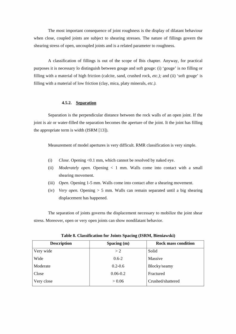
The most important consequence of joint roughness is the display of dilatant behaviour
when close, coupled joints are subject to shearing stresses. The nature of fillings govern the
shearing stress of open, uncoupled joints and is a related parameter to roughness.
A classification of fillings is out of the scope of Ibis chapter. Anyway, for practical
purposes it is necessary lo distinguish between gouge and soft gouge: (i) ‘gouge’ is no filling or
filling with a material of high friction (calcite, sand, crushed rock, etc.); and (ii) ‘soft gouge’ is
filling with a material of low friction (clay, mica, platy minerals, etc.).
4.5.2. Separation
Separation is the perpendicular distance between the rock walls of an open joint. If the
joint is air or water-filled the separation becomes the aperture of the joint. It the joint has filling
the appropriate term is width (ISRM [13]).
Measurement of model apertures is very difficult. RMR classification is very simple.
(i) Close. Opening <0.1 mm, which cannot be resolved by naked eye.
(ii) Moderately open. Opening < 1 mm. Walls come into contact with a small
shearing movement.
(iii) Open. Opening 1-5 mm. Walls come into contact after a shearing movement.
(iv) Very open. Opening > 5 mm. Walls can remain separated until a big shearing
displacement has happened.
The separation of joints governs the displacement necessary to mobilize the joint shear
stress. Moreover, open or very open joints can show nondilatant behavior.
Table 8. Classification for Joints Spacing (ISRM, Bieniawski)
Description Spacing (m) Rock mass condition
Very wide
Wide
Moderate
Close
Very close
> 2
0.6-2
0.2-0.6
0.06-0.2
> 0.06
Solid
Massive
Blocky/seamy
Fractured
Crushed/shattered

4.5.3. Persistence
ISRM [13] classifies the joints as follows.
(i) Persistent. Continuous.
(ii) Subpersistent. Not continuous but several joints can coalesce lo form a
continuous separation surface.
(iii) Not persistent. Not continuous.
RMR classification uses only the first and third classes. Subpersistent joints can be
classified as not continuous before shearing, and continuous after shearing.
4.5.4. Weathering of walls
Table 9 summarizes the recommendations of ISRM [13] for the classification of wall
weathering.
RMR classification mentions only grades I, II and IV. Grade V (completely weathered)
is equivalent lo grade IV (highly weathered) because in both cases the frictional strength of the
joint becomes very low. Grade III (moderately weathered) is an intermediate case.
4.5.5. Parametric rating
RMR descriptions of joint condition classes are clear enough. In many cases the field
conditions fit clearly into one of the classes. But in some intermediate cases the field evidence
does not appear grouped as in the table and some doubts are raised about the correct rating.
The RMR classes represent the frictional component of shear strength of joints and it is
possible to establish the appropriate rating through an estimation of the apparent friction angle.
Some people prefer lo rate separately each one of the subparameters and add the partial rating in
order to obtain an overall rating for condition of discontinuities. Such a method is not
encouraged as a general one but it can be used by less-experienced operators and has the
advantage of being a checking list. Bieniawski [1] has produced a parametric rating of joint
conditions.
Table 10 presents another list of partial parametric ratings for joint conditions which has
been us
eful lo the author when classifying rock slopes. When using this method each of these
four subparameters is assessed and the partial ratings are added to obtain the final rating for the
condition of the joints.
4.6 GROUNDWATER
Groundwater conditions can be estimated in RMR geomechanical classification in three
different ways: (i) inflow of water in tunnels; (ii) pore pressure ratio; and (iii) general
conditions.
For slopes the general conditions are usually sufficiently adequate. The ISRM [13] have
proposed a seepage classification which has been ad
apted lo surfacing joints in order lo estimate groundwater conditions. See Table 11.
Table 9. Classification for Wall Weathering (ISRM)
Grade Term Decomposed rock
(%)
Description
Ia
Ib
II
III
IV
V
VI
Fresh
Fresh
Slightly weathered
Moderately weathered
Highly weathered
Completely weathered
Residual soil
-
-
< 10
10-50
50-90
> 90
100
No visible weathering
Slight discoloration of walls
General discoloration
Part of rock is decomposed. Fresh rock
is a continuum
General decomposition of rock. Some
fresh rock appears
All rock is decomposed. Original
structure remains
All rock is converted to soil. Original
structure is destroyed
Table 10. Partial parametric Ratings for Joint Conditions (Romana)
Roughness/filling Rating
Very rough
Rough
Slightly rough
Smooth
Slickensided or gouge
Soft gouge
10
9
8
6
5
0
Separation Opening Rating
Closed
Moderately open
Open
Very open
< 0.1 mm
0.1-1 mm
1-5 mm
> 5 mm
9
7
5
0
Persistence Rating
Not persistent, not continuous
Subpersistent
Persistent, continuous
5
3
0
Weathering Grade Rating
Fresh
Slightly weathered
Moderately weathered
Highly weathered
Completely weathered
I
II
III
IV
V
6
5
3
0
0
Table 11. Groundwater Conditions (ISRM, Romana)
Unfilled joints Filled joints Description
Joint Flow Filling Flow
Comp. Dry
Damp
Wet
Dripping
Flowing
Dry
Stained
Damp
Wet
Wet
No
NO
No
Occasional
Continuous
Dry
Damp
Wet
Outwash
Washed
No
No
Some drips
Dripping
Continuous
4.7 ORIENTATIONS
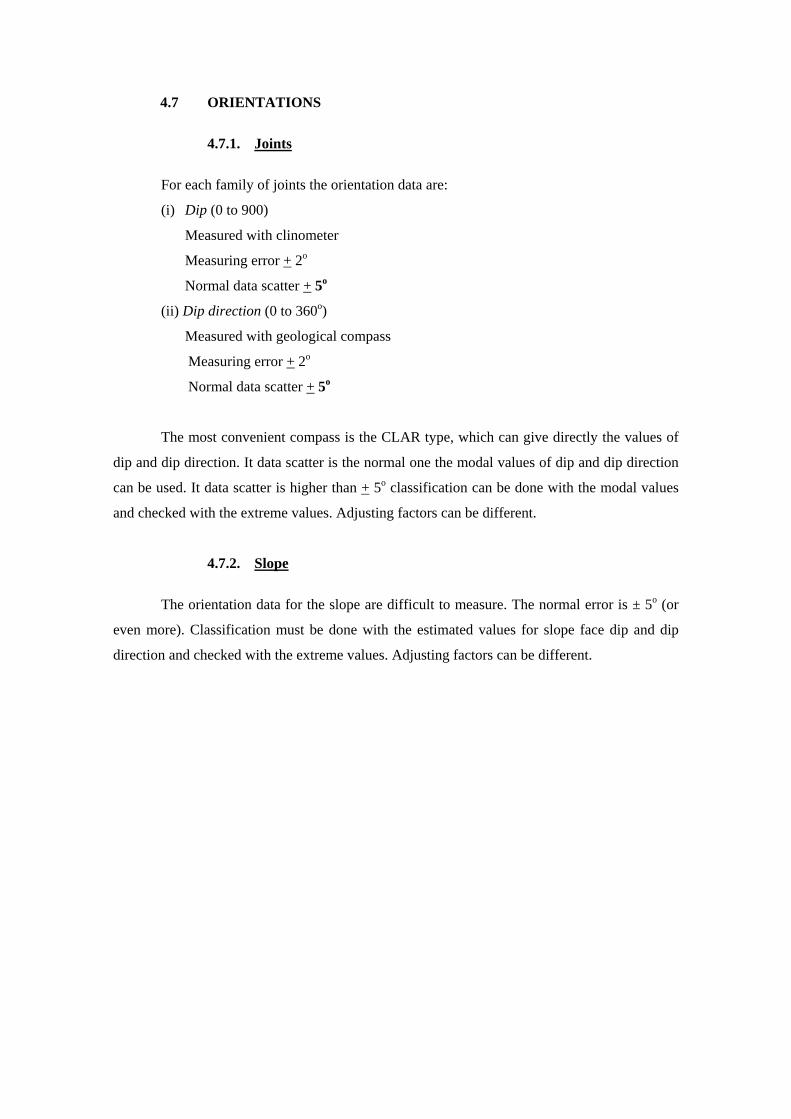
4.7.1. Joints
For each family of joints the orientation data are:
(i) Dip (0 to 900)
Measured with clinometer
Measuring error + 2o
Normal data scatter + 5o
(ii) Dip direction (0 to 360o)
Measured with geological compass
Measuring error + 2o
Normal data scatter + 5o
The most convenient compass is the CLAR type, which can give directly the values of
dip and dip direction. It data scatter is the normal one the modal values of dip and dip direction
can be used. It data scatter is higher than + 5o classification can be done with the modal values
and checked with the extreme values. Adjusting factors can be different.
4.7.2. Slope
The orientation data for the slope are difficult to measure. The normal error is ± 5o (or
even more). Classification must be done with the estimated values for slope face dip and dip
direction and checked with the extreme values. Adjusting factors can be different.
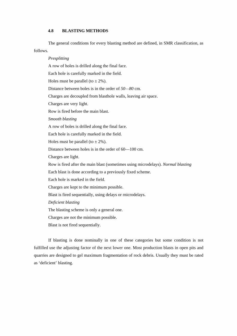
4.8 BLASTING METHODS
The general conditions for every blasting method are defined, in SMR classification, as
follows.
Presplitting
A row of holes is drilled along the final face.
Each hole is carefully marked in the field.
Holes must be parallel (to ± 2%).
Distance between boles is in the order of 50—80 cm.
Charges are decoupled from blasthole walls, leaving air space.
Charges are very light.
Row is fired before the main blast.
Smooth blasting
A row of boles is drilled along the final face.
Each hole is carefully marked in the field.
Holes must be parallel (to ± 2%).
Distance between holes is in the order of 60—100 cm.
Charges are light.
Row is fired after the main blast (sometimes using microdelays). Normal blasting
Each blast is done according to a previously fixed scheme.
Each hole is marked in the field.
Charges are kept to the minimum possible.
Blast is fired sequentially, using delays or rnicrodelays.
Deficient blasting
The blasting scheme is only a general one.
Charges are not the minimum possible.
Blast is not fired sequentially.
If blasting is done nominally in one of these categories but some condition is not
fulfilled use the adjusting factor of the next lower one. Most production blasts in open pits and
quarries are designed to gel maximum fragmentation of rock debris. Usually they must be rated
as ‘deficient’ blasting.
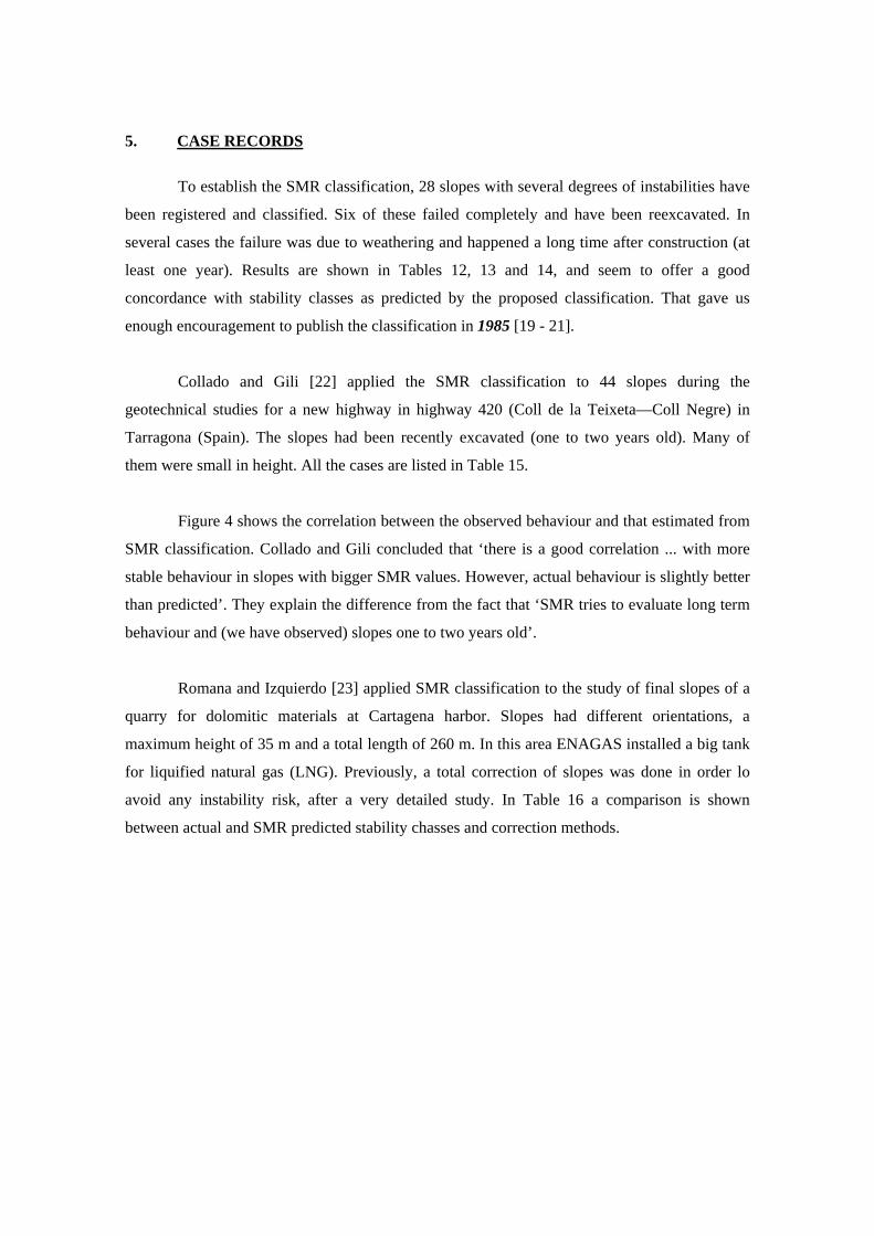
5. CASE RECORDS
To establish the SMR classification, 28 slopes with several degrees of instabilities have
been registered and classified. Six of these failed completely and have been reexcavated. In
several cases the failure was due to weathering and happened a long time after construction (at
least one year). Results are shown in Tables 12, 13 and 14, and seem to offer a good
concordance with stability classes as predicted by the proposed classification. That gave us
enough encouragement to publish the classification in 1985 [19 - 21].
Collado and Gili [22] applied the SMR classification to 44 slopes during the
geotechnical studies for a new highway in highway 420 (Coll de la Teixeta—Coll Negre) in
Tarragona (Spain). The slopes had been recently excavated (one to two years old). Many of
them were small in height. All the cases are listed in Table 15.
Figure 4 shows the correlation between the observed behaviour and that estimated from
SMR classification. Collado and Gili concluded that ‘there is a good correlation ... with more
stable behaviour in slopes with bigger SMR values. However, actual behaviour is slightly better
than predicted’. They explain the difference from the fact that ‘SMR tries to evaluate long term
behaviour and (we have observed) slopes one to two years old’.
Romana and Izquierdo [23] applied SMR classification to the study of final slopes of a
quarry for dolomitic materials at Cartagena harbor. Slopes had different orientations, a
maximum height of 35 m and a total length of 260 m. In this area ENAGAS installed a big tank
for liquified natural gas (LNG). Previously, a total correction of slopes was done in order lo
avoid any instability risk, after a very detailed study. In Table 16 a comparison is shown
between actual and SMR predicted stability chasses and correction methods.
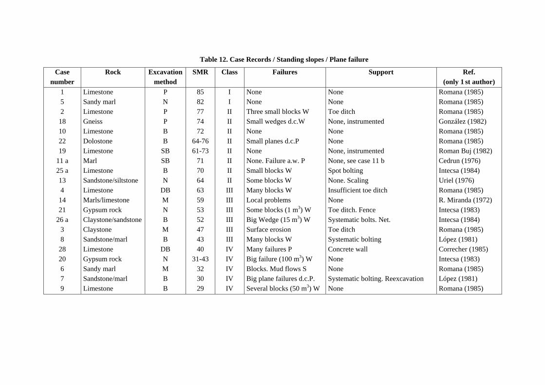
Table 12. Case Records / Standing slopes / Plane failure
Case number
Rock Excavation method
SMR Class Failures Support Ref. (only 1 st author)
1 5 2
18 10 22 19
11 a 25 a 13 4
14 21
26 a 3 8
28 20 6 7 9
Limestone Sandy marl Limestone Gneiss Limestone Dolostone Limestone Marl Limestone Sandstone/siltstone Limestone Marls/limestone Gypsum rock Claystone/sandstone Claystone Sandstone/marl Limestone Gypsum rock Sandy marl Sandstone/marl Limestone
P N P P B B
SB SB B N
DB M N B M B
DB N M B B
85 82 77 74 72
64-76 61-73
71 70 64 63 59 53 52 47 43 40
31-43 32 30 29
I I II II II II II II II II III III III III III III IV IV IV IV IV
None None Three small blocks W Small wedges d.c.W None Small planes d.c.P None None. Failure a.w. P Small blocks W Some blocks W Many blocks W Local problems Some blocks (1 m3) W Big Wedge (15 m3) W Surface erosion Many blocks W Many failures P Big failure (100 m3) W Blocks. Mud flows S Big plane failures d.c.P. Several blocks (50 m3) W
None None Toe ditch None, instrumented None None None, instrumented None, see case 11 b Spot bolting None. Scaling Insufficient toe ditch None Toe ditch. Fence Systematic bolts. Net. Toe ditch Systematic bolting Concrete wall None None Systematic bolting. Reexcavation None
Romana (1985) Romana (1985) Romana (1985) González (1982) Romana (1985) Romana (1985) Roman Buj (1982) Cedrun (1976) Intecsa (1984) Uriel (1976) Romana (1985) R. Miranda (1972) Intecsa (1983) Intecsa (1984) Romana (1985) López (1981) Correcher (1985) Intecsa (1983) Romana (1985) López (1981) Romana (1985)
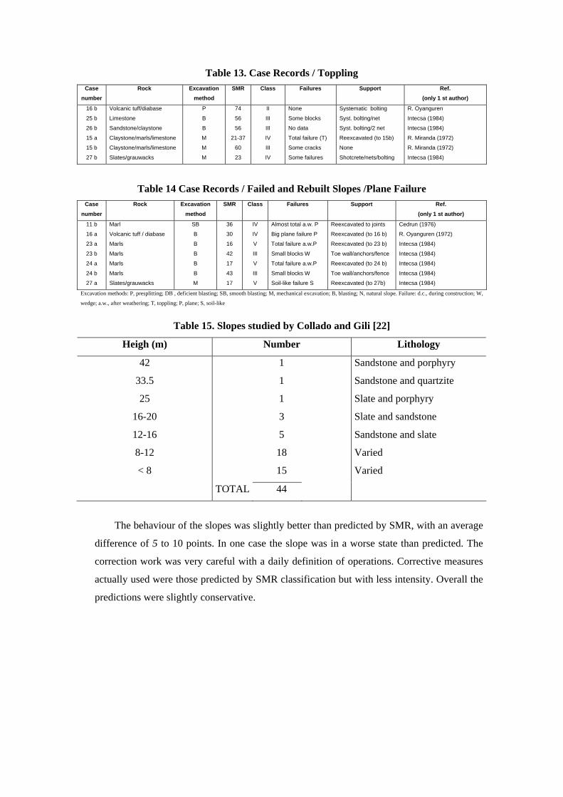
Table 13. Case Records / Toppling Case
number Rock Excavation
method SMR Class Failures Support Ref.
(only 1 st author)
16 b
25 b
26 b
15 a
15 b
27 b
Volcanic tuff/diabase
Limestone
Sandstone/claystone
Claystone/marls/limestone
Claystone/marls/limestone
Slates/grauwacks
P
B
B
M
M
M
74
56
56
21-37
60
23
II
III
III
IV
III
IV
None
Some blocks
No data
Total failure (T)
Some cracks
Some failures
Systematic bolting
Syst. bolting/net
Syst. bolting/2 net
Reexcavated (to 15b)
None
Shotcrete/nets/bolting
R. Oyanguren
Intecsa (1984)
Intecsa (1984)
R. Miranda (1972)
R. Miranda (1972)
Intecsa (1984)
Table 14 Case Records / Failed and Rebuilt Slopes /Plane Failure Case
number Rock Excavation
method SMR Class Failures Support Ref.
(only 1 st author)
11 b
16 a
23 a
23 b
24 a
24 b
27 a
Marl
Volcanic tuff / diabase
Marls
Marls
Marls
Marls
Slates/grauwacks
SB
B
B
B
B
B
M
36
30
16
42
17
43
17
IV
IV
V
III
V
III
V
Almost total a.w. P
Big plane failure P
Total failure a.w.P
Small blocks W
Total failure a.w.P
Small blocks W
Soil-like failure S
Reexcavated to joints
Reexcavated (to 16 b)
Reexcavated (to 23 b)
Toe wall/anchors/fence
Reexcavated (to 24 b)
Toe wall/anchors/fence
Reexcavated (to 27b)
Cedrun (1976)
R. Oyanguren (1972)
Intecsa (1984)
Intecsa (1984)
Intecsa (1984)
Intecsa (1984)
Intecsa (1984)
Excavation methods: P, presplitting; DB , deficient blasting; SB, smooth blasting; M, mechanical excavation; B, blasting; N, natural slope. Failure: d.c., during construction; W,
wedge; a.w., after weathering; T, toppling; P, plane; S, soil-like
Table 15. Slopes studied by Collado and Gili [22]
Heigh (m) Number Lithology
42
33.5
25
16-20
12-16
8-12
< 8
1
1
1
3
5
18
15
Sandstone and porphyry
Sandstone and quartzite
Slate and porphyry
Slate and sandstone
Sandstone and slate
Varied
Varied
TOTAL 44
The behaviour of the slopes was slightly better than predicted by SMR, with an average
difference of 5 to 10 points. In one case the slope was in a worse state than predicted. The
correction work was very careful with a daily definition of operations. Corrective measures
actually used were those predicted by SMR classification but with less intensity. Overall the
predictions were slightly conservative.
6. STABILITY CLASSES
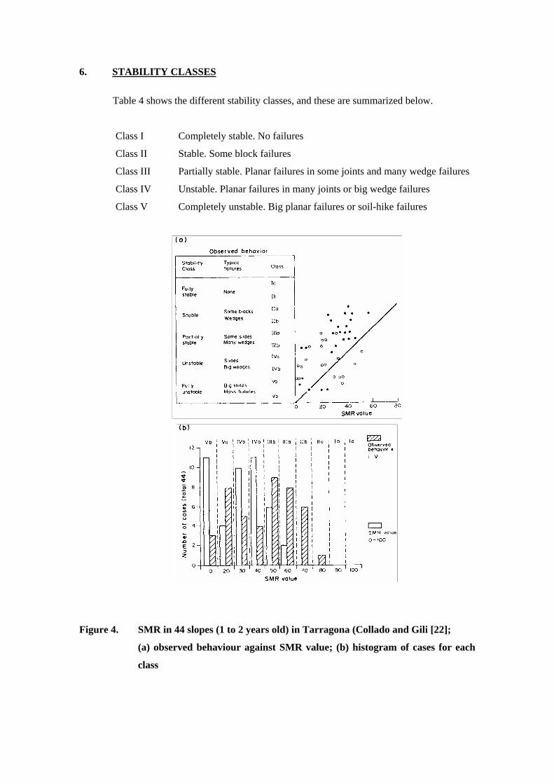
Table 4 shows the different stability classes, and these are summarized below.
Class I Completely stable. No failures
Class II Stable. Some block failures
Class III Partially stable. Planar failures in some joints and many wedge failures
Class IV Unstable. Planar failures in many joints or big wedge failures
Class V Completely unstable. Big planar failures or soil-hike failures
Figure 4. SMR in 44 slopes (1 to 2 years old) in Tarragona (Collado and Gili [22];
(a) observed behaviour against SMR value; (b) histogram of cases for each
class

Table 16. Predicted and Actual Behavior of Cap Negre Slopes
(Romana and Izquierdo [23])
Stability class Correction(a) RMR
SMR Actual SMR Actual
54-61
20-40
55-65
42-54
III a
IV
III a – II b
III b
II b
III
III a
III b
sB sS
W
sB pS
sB sG (M)
pS
W
pB pS
pB R
The empirically found limit values of SMR for the different failure modes are listed in
Table 17. All slopes with SMR values below 20 fail very quickly. No slope has been registered
with SMR value below 10. These slopes would not be physically feasible.

7. SUPPORT MEASURES
7.1 GENERAL
Many different remedial measures can be taken to support an unstable slope, or to
prevent a believed potential instability. There is not enough technical literature about the real
effects of support measures in rock slopes, especially when different measures are adopted
simultaneously. On the other hand many case histories document analytically the correction of
landslides in soil using deep drainage and/or resistant inclusions in the slopes.
SMR Plane/failures Wedge
> 75
60-75
40-55
15-40
None
None
Big
Major
None
Some
Many
No
SMR Toppling failures SMR Soil-like failures
> 65
50-65
30-35
None
Minor
Major
30
10-30
None
Possible
The study of potentially unstable rock slopes is a difficult task requiring careful field
work, detailed analysis and good engineering sense in order to understand the relative
importance of the several instability factors acting on the slope. No classification system can
replace all that work. However, they may be of son utility in indicating the normal limits of use
for each class of support measures. The choice between them is out of the scope of the
classification system.
The support measures can be grouped in six different classes.
(i) No support None
Scaling
(ii) Protection Toe ditches
Fences (at toe or in the slope)
Nets (over the slope face)
(iii) Reinforcement Bolts
Anchors
(iv) Concreting Shotcrete
Dental concrete
Ribs and/or beams
Toe walls
(v) Drainage Surface
Deep
(vi) Reexcavation
From the collected case histories Table 18 presents the more common support measures
for each class interval (see also Figure 5).
Normally no support measures are needed for slopes with SMR values of 75-100. There
are some stable slopes with SMR values of 65.
Total reexcavation of a slope is a drastic measure, normal in soil slopes, but less
practical in rock ones, except in the instability mode is planar through a big continuous joint. It
may be adopted in order to reduce its grade, to take away weight in its upper part and/or to add a
stabilizing weight at the toe. No totally reexcavated slope has been found with SMR value over
30. No slope has been found with a SMR value below 10. Probably such a low value would
imply total and instant instability, the excavation of the slope (even during a very short time)
would not be physically feasible.
In a broad sense, the ranges of SMR for each class of support measures are listed in
Table 19. Selection of the adequate measures must be made taking into account the prevalent
failure mechanism and also the frequency of joints. Two parameters can be useful to quantify
frecuency of joints.
(i) Joint spacing, S. The modal value of joint spacing distribution in a family. Frequently the
governing joint spacing value corresponds to the joints family which originates the
instability.
(ii) Joint volumetric count, Jv. The number of joints per cubic meter, Jv, can evaluated with
the formula.
∑= iv SJ /1

where iS is the mean (not the modal) spacings for each joints family. The ISRM ‘Suggested
Method for the Quantitative Description of Discontinuities in Rock Masses’ [13] gives the
following:
Table 18. Recommended Support Measures for Each Stability Class
Class SMR Support
Ia
Ib
II a
II b
III a
III b
IV a
IV b
V a
91-100
81-90
71-80
61-70
51-60
41-50
31-40
21-30
11-20
None
None. Scaling
(None. Toe ditch or fence)
Spot bolting
Toe ditch or fence. Nets
Spot or systematic bolting
Toe ditch and/or nets
Spot or systematic bolting
Spot shotcrete
(Toe ditch and/or nets)
Systematic bolting. Anchors
Systematic shotcrete
Toe wall and/or dental concrete
Anchors
Systematic shotcrete
Toe wall and/or concrete
(Reexcavation) Drainage
Systematic reinforced shotcrete
Toe wall and/or concrete
Reexcavation. Deep drainage
Gravity or anchored wall
Reexcavation (i) Very often several different support methods are used in the same slope.
(ii) Less usual support measures are in brackets

Figure 5. Correction methods according to SMR range
Table 19. Range of SMR for Support Measure Classes
SMR Support measures
65-100
45-70
30-75
20-60
10-40
10-30
None. Scaling
Protection
Reinforcing
Concreting
Drainage
Toe walls. Reexcavation
Description of block sizes according to Jv.
Description of blocks Jv (joints m-3)
Very large
Large
Medium
Small
Very small
Crushed rock
< 1
1-3
3-10
10-30
30-60
> 60
Jv and RQD can be approximately correlated through the Palmstrom [17] formula
RQD = 115 – 3.3 Jv RQD < 100
7.2 PROTECTION MEASURES
7.2.1. Toe ditch
Toe ditches are useful to keep fallen rocks out of the road when failures are wedges,
planes and/or minor topples.
Ritchie [24] filmed rockfalls in several slopes, identifying three fall modes: (i) direct
fall, for slopes 1H:4V and steeper; (ii) rebound, for slopes around 1H:2V; and (iii) roll, for
slopes 1H:1V and flatter.
Ritchie also proposed empirical criteria for dimensioning ditches and fences (Table 20).
These values have been widely reproduced and quoted. Nevertheless many engineers believe
that Ritchie´s values are too big and lead to designs that are too expensive. Whiteside [25]
(based on Fookes and Sweeney [26]) has published an abacus reducing Ritchie´s proposed
dimensions.
On the other hand Ritchie seems to have worked with slopes in hard rocks, therefore
having high rebound coefficients. In softer rocks part of the rebound energy is lost in breakout,
and the distances to the slope toe are smaller.
Castañeda [27] has proposed, and used ssuccessfully, a reduction of Ritchie´s criteria
for highway slopes in the north of Spain, excavated in marls, lutites, soft sandstones, etc (Table
21). His results are very similar to these given by Whiteside. Ritchie´s rules seem more

adequate for slopes when Co > 25 MPa and F4 < 0 (normal blasting). Castañeda´s reductions
can be used for slopes when Co > 25 MPa (soft rock) and F4 < 0 (careful blasting).
Table 20. Ditch Dimensions According to Ritchie [24]
Height (m) 1H:4V/1H:3V 1H:2V Slopes
3H:4V
1H:1V 5H:4V
4.5-9
9-18
18-30
> 30
3.0 x 0.9
4.5 x 1.2
6.0 x 1.2
6.0 x 1.2
3.0 x 0.9
4.5 x 1.2
6.0 x 1.8 F
705 x 1.8 F
3.0 x 1.2
4.5 x 1.8
6.0 x 1.8 F
7.5 x 2.4 F
3.0 x 0.9
4.5 x 1.2
4.5 x 1.8 F
4.5 x 1.8 F
3.0 x 0.9
3.0 x 1.5 F
4.5 x 1.8 F
4.5 x 1.8 F W width (m); D, depth (m) (W x D), F means that ditch depth can be 1.20 m with a fence to total depth.
Table 21. Ditch Dimensions According to Castañeda [27]
Height (m) Slope
1H:4V / 2H:3V
Height (m) Slope
2H:3V/1H:1V
10-25
25-40
> 40
2.2 x 1.2
3.2 x 1.6
3.7 x 2.0
6 – 20
> 20
2.2 x 1.2
3.5 x 1.8
W width (m); D, depth (m) (W x D)
Table 22. Indicative Conditions for Use of Nets (Romana)
Jv Type of net Block weight (kN)
5-10
> 10
Reinforced
Normal
1.5-5
> 1.5
7.2.2. Nets
Nets over the slope are used to avoid free fall of rock pieces. Therefore they are useful
for wedge failures and also with minor topples (although in this case securing the net at the top
of the slope can be difficult). To avoid breaks of the net caused by the excessive weitht of rock
fragments, nets must be used only when slopes have big values of Jv. Table 22 gives some
indications about the use of nets in slopes.
7.3 REINFORCEMENT
7.3.1. Bolting
Bolting in slopes is a worldwide used technique, but no specific rules for design and
layout of bolts are offered in the technical literature. The following were derived from the
author´s experience and are partially inspired by the excellent and concise manual by Schach,
Garshol and Heltzen [28], dedicated mostly to underground bolting.
Bolts in slopes are used as a combined immediate and permanent support. The bolt
types are detailed below.
(i) Fuly grouted. Not tensioned
Normally rebar type (20-25 mm diameter)
Grouted with resin or mortal
Not (or very lightly) tensioned at head.
Sometimes ‘perfo’ type, with a thin, perforated metal tube split longitudinally,
filled with mortar.
(ii) Tensioned
Normally expansion type (split and wedge).
With a bearing plate
Tensioned at head.
Grouted alterwards with mortar to prevent corrosion.
For the sake of simplicity only the untensioned, fully grouted bolts are referred to in this
section. The undergrouted and/or tensioned bolts are best included with the anchors. Bolts are
defined then as a ‘passive’ reinforcement, anchors being an ‘active’ one.
Simple passive, grouted bolts have the following characteristics:
Length Normally 3 to 4 m
Should reach 1-2 m in solid rock, across the unstabilizing joint
As a rule of thumb, bigger than height of slope divided by ten
Diameter Normally 22 mm
Strength 120 to 150 kN
They are very appropiate to support slopes with wedges, planes and/or minor topples.
From the point of view of bolting, rock masses can be classified according to the joint
frequency in the following types of rock.
(i) Blocky, hard rock
Typical joint spacing over 1 m
Joint volumetric count, Jv = 1-3
Systematic bolting at 3-3.5 m distance
(ii) Fractured, hard rock
Typical joint spacing between 0.3 and 1 m
Joint volumetric count, Jv = 3-10
Systematic bolting at 1-3 m distances (three times the prevalent joint spacing).
(iii) Very fractured, hard rock
Typical joint spacing smaller than 0.3 m
Joint volumetric count Jv > 10.
Systematic bolting at 1 m distance combined with a continuous, thick layer of
shotcrete (15-25 cm) if Jv = 10-18.
(iv) Weathered rock, with open or clay-filled joints
Bolting to secure hanging blocks, through the joints to sound rock.
Bolting distance and length in a selected pattern to suit rock and joint
disposition.
(v) Soft rocks
Normally bolts are of limited use in very soft rocks, because they cannot
develop full tension.
In soft rocks bolts can be used combined with continuous reinforced thick layers
of shotcrete.
The rock conditions for an adequate use of bolting are summarized in Table 23.
Some indications of possible bolt pattern in relation to the SMR stability classes are
noted in Table 24.
7.3.2. Anchoring
Anchors are long steel bars which apply an active force in the surface of the slope,
transferring it to the ground behind the unstable zone. They introduce a stabilizing force and
simultaneously increase shear strength in joints.
Many types of anchors can be used. Their characteristics can be summarized as follows.
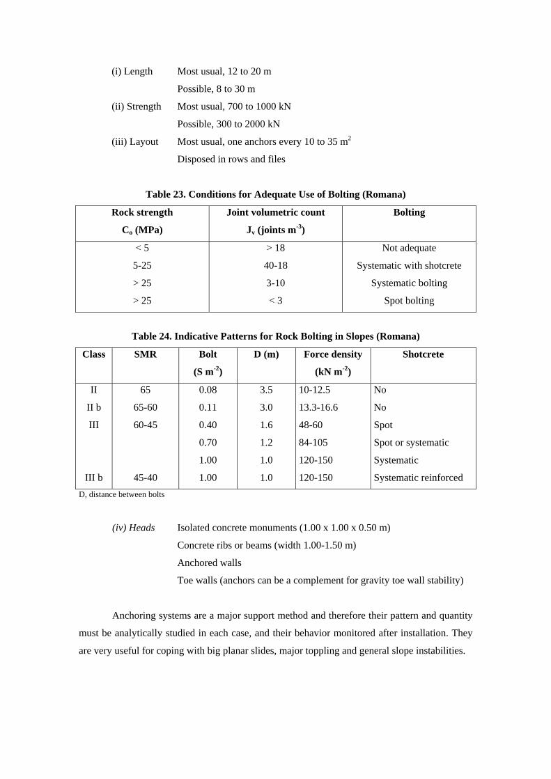
(i) Length Most usual, 12 to 20 m
Possible, 8 to 30 m
(ii) Strength Most usual, 700 to 1000 kN
Possible, 300 to 2000 kN
(iii) Layout Most usual, one anchors every 10 to 35 m2
Disposed in rows and files
Table 23. Conditions for Adequate Use of Bolting (Romana)
Rock strength
Co (MPa)
Joint volumetric count
Jv (joints m-3)
Bolting
< 5
5-25
> 25
> 25
> 18
40-18
3-10
< 3
Not adequate
Systematic with shotcrete
Systematic bolting
Spot bolting
Table 24. Indicative Patterns for Rock Bolting in Slopes (Romana)
Class SMR Bolt
(S m-2)
D (m) Force density
(kN m-2)
Shotcrete
II
II b
III
III b
65
65-60
60-45
45-40
0.08
0.11
0.40
0.70
1.00
1.00
3.5
3.0
1.6
1.2
1.0
1.0
10-12.5
13.3-16.6
48-60
84-105
120-150
120-150
No
No
Spot
Spot or systematic
Systematic
Systematic reinforced D, distance between bolts
(iv) Heads Isolated concrete monuments (1.00 x 1.00 x 0.50 m)
Concrete ribs or beams (width 1.00-1.50 m)
Anchored walls
Toe walls (anchors can be a complement for gravity toe wall stability)
Anchoring systems are a major support method and therefore their pattern and quantity
must be analytically studied in each case, and their behavior monitored after installation. They
are very useful for coping with big planar slides, major toppling and general slope instabilities.

A rough guide for the preliminary quantification of the anchoring needs in a slope in
presented in Table 25. The author has produced the table, deriving the data from some cases
where major nachoring was successful as the principal means of stabilizing the slope.
When anchors are used to help as an additional measure to increase the stability of
gravity walls or rib systems, the force density should be in the order of 25-50 kN m-2 (minimum
15 kN m-2).
7.4 CONCRETING
7.4.1. Shotcrete
Shotcreting a slope is easy, it can be done quickly, and very often it is a profitable work.
Therefore many slopes are shotcreted when the first signs of instability appear. It is difficult to
assess the real effect of shotcrete in slopes. Often the shotcrete layer decays with time, cracking
and falling. Sometimes a surface net has been installed to prevent shotcrete pieces from falling
into the road after cracking.
Spot shotcrete can be useful when local corrections and/or protections are needed (e.g.
against overhanging) and when differential erosion can damage a slope. Systematic shotcrete is
necessary in slopes supported with systematic bolting when the rock mass is fragmented (joint
volumetric mass, Jv = 10-18), and can be used to distribute the forces of isolated anchor heads.
If shotcrete is used as a general protection for erodible or soft rock in a slope care
should be taken to ensure that the following rules are observed.
(i) Clear previously the slope (with compressed air and water).
(ii) Use several layers. A convenient layout includes a preliminary surface layer (e
= 3 cm), and two protection layers with reinforcement (e = 2 x 10 cm).
(iii) Use short bolts to secure shotcrete to the rock mass.
(iv) Absolutely avoid shotcreting the areas with natural drainage to the slope face in
order to avoid developing bigger internal water pressures in joints and/or pores,
which can be dangerous.
(v) Try to install drains to alleviate internal water pressures. Experience shows that
most of these drains do not work properly, and remain dry even when they are
very close to water-bearing cracks in shotcrete.
The beneficial effects of systematic shotcrete are doubtful, and it can be harmful for the
natural drainage of the rock mass. Futhermore, the aesthetic effect of shotcrete is very bad,
although it can be bettered by using clear pigments in the final layer.
7.4.2. Dental concrete
Dental concrete is adequate for local corrections in generally stable slopes. It can be
substituted by mansory. This has advantages when the mansory is formed from the same rock as

the slope (similar resistance to weathering and a better, unobtrusive view). In any case, dental
concrete must avoid the disturbance of the natural drainage system in rock masses.
7.4.3. Ribs, beams and walls
Concrete ribs and beams can serve as a resistant grid for the slope. Often the crossings
include anchors, the support system being a combination of both factors. Toe walls have similar
functions and can also be combined with anchors. Fully unstable slopes can be stabilized with
gravity walls, with or without anchors. In these cases the force densities of the anchors can be
smaller. Continuous walls must include effective provisions for deep drainage of the rock mass.

7.5 DRAINAGE
7.5.1. Surface drainage
The surface drainage can be a great help for the stability of a slope. At the top of a slope
water can be ponded in open tension cracks. Water pressure develops, proportionally to the
square of crack depth, and is a very dangerous destabilizing force. In the face of the slope the
running water may cause erosion in soft zones. This can lead to local instabilities.
Surface drains can be ditches at the top of the slope, more or less parallel to it. Across
the face vertical ditches, at regular spacing, can collect the water falling from the upper part,
protecting the slope.
Surface drainage must be very well done to be effective. Concrete ditches can crack and
inject water into the joints instead of draining the slope. Drainage conduits must be lined
preferably with soft and/or extensible materials which can accommodate to the slope
deformations. They must be provided with ample and safe evacuation devices.
7.5.2. Deep drainage
Water percolates in rock masses through the joints system. The conductivity of the
joints is proportional to the cube of their width. The presence of fill in the joints makes them
nonpermeable. Near the surface, joints tend to be open and very permeable. For these reason
internal water pressure is a less important cause of instability in rock masses than in soil slopes.
Many soil landslides can be fully corrected (or at least slowed) by internal drainage
only. In rock slopes internal drainage must be used in conjunction with other support measures
(anchoring and/or walls).
The possible deep drainage systems are as follows.
(i) Horizontal toe drains (‘French’ or ‘Californian’)
Bored horizontally (with a very small inclination) from the slope toe.
Must include filters to prevent suffusion.
Short lived if the slope undergoes deformation.
Very effective to eliminate water pressure from the slope surface.
(ii) Vertical drains
Bored vertically from the slope.
Very effective if there is a perched water level in th slope.
(iii) Horizontal drainage adits
Parallel to the slope.
The most effective measure.
Not usual in civil engineering (except dams).
Deep drainage is only useful when a continuous groundwater level surfaces the
slope, a situation which requires a very humid climate and/or joints with big
horizontal conductivity. Deep drainage is a good support measure for big planar
slides or mass instabilities.
The design details of drainage by subhorizontal (‘Californian’ or ‘French’) drains can
be derived from Louis.
(i) Optimal length of drains
0,20 to 0,30 Hw (Hw is the height of the groundwater level over the toe of the
slope at a distance of Usually from 6 to 12 m.
(ii) Optimal distance between drains
0,33 to 0,50 the length of the drains
Usually from 2 to 6 m.
(iii) Optimal direction
Theoretically 10o to 15o downslope
Usually horizontal.
5o to 10o upslope is water flow has to clear eventual debris in the borings.
(iv) Optimal material
Plastic ranured PVC tube.
Geotextile filter around the tube to protect drains against suffusion.
8. CONCLUSIONS
The new method presented, called Slope Mass Rating (SMR), allows the use of the
Bieniawski (CSIR) classification for slopes. It requires the same data and gives a forecast of
stability problems and support techniques for slopes in each stability class. More research is
needed, and will be welcome, to check the proposed classification system.
ACKNOWLEDGEMENT
The author wants to express his gratitude to Carol and John Hudson who generously
encouraged him to write this chapter.
9. REFERENCES
BIENIAWSKI Z.T. Engineering classification of jointed rock masses. Trans. S. Afr. Inst. Civ.
Eng. 15, 355-3344 (1973).
BIENIAWSKI Z.T. Rock mass classification in rock engineering. In Proc. Symp. Exploration
for Rock Eng., vol 1, pp 97-106. Balkema, Rotterdam (1976).
BIENIAWSKI Z.T. The Geomechanics Classification in rock engineering applications. In Proc.
4 th Int. Congr. Rock Mech., Montreux, chap. 5 pp 55-95. Balkema, Rotterdam (1979).
BIENIAWSKI Z.T. Rock Mechanics Design in Mining and Tunnelling, chap. 55, pp. 55-95
Balkema, Rotterdam (1984).
BIENIAWSKI Z.T. Engineering Rock Mass Classifications. Wiley, New York (1989).
BIENIAWSKI Z.T. and ORR C. M. Rapid site appraisal for dam foundations by Geomechanics
Classification. In Proc. 12 th Int. Congr. Large Dams, Q 46, R32, pp 483-501. ICOLD,
Mexico (1976).
CASTAÑEDA R. Algunos tratamientos de taludes rocosos en carreteras frente a desórdenes
superficiales. Simp. Nal.. sobre Rocas Blandas. SEMR, Madrid (1976).
COLLADO A. and GILI J. A. A geological geotechnical study for highway 420 (Coll de la
Teixeta-Coll Negre) in Tarragona (in Spanish). Not published. Univ. Polyt. Of Catalunya,
Barcelona (1988).
DEERE P.V. Technical description of cores for engineering purposes. Felsmech Ingenieurgeol.
1, 16-22 (1964).
FOOKES P.G. and Sweeney M. Stabilization and control of local rockfalls in degrading rock
slopes. Q. J. Eng. Geol. 9, 37-55 (1976).
GOODMAN R.E. Methods of Geological Engineering, pp 192-199. West Publishing, San
Francisco (1976).
HARAMY K. Y. and DeMarco M.J. Use of the Schmidt hammer for rock and coal testing. In
Proc. 26 th U.S. Symp. Rock Mech., Rapid City, SD (Edited by E. Ashworth), pp 549-
555. Balkema, Rotterdam (1985).
ISRM SUGGESTED METHODS Quantitative description of discontinuities in rock masses.
Int. J. Rock Mech. Min. Sci. & Geomech. Abstr. 15, 319-368 (1978).
ISRM SUGGESTED METHODS Determining hardness and abrasiveness of rocks. Int. J. Rock
Mech. Min. Sci. & Geomech. Abstr. 15, 89-97 (1978).
KENDORSKI F.S., CUMMINGS R.A., BIENIAWSKI Z.T. and SKINNER E.H. Rock mass
classification for block caving mine drift support. In Proc. 5 th Int. Congr. Rock Mech.,
Melbourne, Section B. Balkema, Rotterdam (1983).
LOUIS C. Hidraulique des roches. These de Doctorat. Université de Paris (1974).
PALMSTROM A. Characterizing the degree of jointing and rock mass quality. Internal report.
Berdal, Oslo (1975).
PRIEST S.D. and HUDSON J.A. Discontinuity spacing in rock Int J. Rock Mech. Min Sci &
Geomech Abstr. 13, 134-153 (1976).
RITCHIE A. M. The evaluation of rockfall and its control. Highw. Res. Rec. 17, 13-28 (1963).
ROMANA M. Nuevos factores de ajuste para la aplicación de la clasificación de Bieniawski a
los taludes. Jorn. Geotéc. Nac. (1985).
ROMANA M. New adjustment ratings for application of Bieniawski classification to slopes. In
Proc. Int. Symp. On the Role of Rock Mech., pp 49-53. Zacatecas (1985.
ROMANA M. Practice of SMR classification for slope appraisal. In Proc. 5 th Int. Symp. On
Landslides, Lausanne. Balkema, Rotterdam (1988).
ROMANA M. and IZQUIERDO F. La reparación del desmonte de Cap Negre In 2 nd Simp.
Nal. sobre Taludes, pp 525-534. Andorra (1988).
SCHACH R., GARSHOL K. and HELTZEN A. M. Rock bolting. A practical handbook.
Pergamon Press, Oxford (1979).
SERAFIM J.L. and PEREIRA J.P. Considerations on the Geomechanics Classification of
Bieniawski. In Proc. Int. Symp. Eng. Geol. and Underground Construction, Lisbon, vol. 1,
pp II 31-II 42 (1983).
STEFFEN O.K.H. Research and development needs in data collection for rock engineering In
Proc. Symp. Exploration for Rock Eng. Vol 2, pp 95-104, Rotterdam (1976).
SWINDELLS C.F. The detection of blast induced fracturing to rock slopes. In Proc. Int Symp.
On the Role of Rock Mech pp 81-86 Zacatecas (1985).
WHITESIDE P.G.D. Rockfall and its control. Disc to Session 7. In Symp. On Rock
Engineering and Excavation in an Urban Environment. I.M.M., Hong Kong (1986).