stmr art dmrdamsfoundations
TRANSCRIPT
8/13/2019 STMR Art DMRDamsFoundations
http://slidepdf.com/reader/full/stmr-art-dmrdamsfoundations 1/12
STMR 9º Congresso Luso de Geotecnia. Aveiro, 2004
Manuel Romana Ruiz 1
DMR (an adaptation of RMR), a new geomechanics classification
for use in dams foundations.
DMR (adaptado del RMR), uma nova classificaçao geomecanicapra usar nas fondaçoes de barragens.
Romana, Manuel. Universidad Politécnica de Valencia, Spain. [email protected]
ABSTRACT
Some topics, which difficult the effective use of RMR for dam foundations, are reviewed and a new geomechanicsclassification system, DMR (Dam Mass Rating), is proposed -as an adaptation of RMR- giving tentative guidelines
for several practical aspects in dam engineering and for the appraisal of dam foundations in preliminary studies(overall stability against sliding, needed depth of excavation for the foundations, consolidation grouting treatment, possible consequences of excessive relationship -following Rocha concepts- between the deformation modulus ofthe dam and of the rock mass foundation) taking account of the effects of rock mass anisotropy and of the watersaturation. The formulae for estimation of the rock mass deformation modulus Em are also discussed. The DMRmethod can be useful when assessing the safety conditions of old dams, which are not well technically documented.
1 INTRODUCTION
A large dam is, almost always, a unique work, adapted to the morphology and the strength of the foundation, andalso to the hydrological regime of the river. The dam, and the impounded water, interact with a great mass ofterrain, very far away sometimes from the dam itself. The design and construction of a dam, are complex andcasuistic, difficult to standardize. Nevertheless dams are classified and there is a “taxonomy” of the different damclasses. It is usual, when designing a dam, to refer it to precedents of similar dams in similar terrains. Needs ofterrain strength and deformability quantification are quite different for each type of dam: arch, gravity (CVC , RCCor hardfill), CFRD, AFRD, rockfill, earthfill… As a rule of thumb concrete dams (and the face of CFRD/AFRD)require rock foundations whereas fill dams can be founded in soil.
Anyway it is widely accepted as good practice to fix the most important properties of a dam foundation referringthem to some quality index (i.e. geotecnic zoning, seismic velocity of P-waves, weathering degree…). These properties are mainly permeability (frequently expressed in Lugeon units), shear strength of the foundation (in mostcases cohesion and friction of the rock mass and/or of the governing joints), and terrain deformability. The dammust retain water, have enough safety against global sliding and adjust itself to the terrain deformations without
too much cracking in service.
Therefore it is very convenient to arrange the quantitative data obtained from geologic-geotecnic field investigationattending to some previous idea about the importance of each one in face of dam design, construction andoperation. And this is the concept which informs the geomechanics classifications. A very interesting precedent isthe so called “Engevix preclassification” used in Itaipú to cope with the enormous amount of geotechnic data forthe foundation of the long lateral wing dykes of the main dam. It was developed by Cruz (1976) and can bereviewed in Camargo et al (1978) and John (1978). Basically it is a rating system for the different properties of therock mass attending to their effects in the dam foundation safety. Other interesting precedent is the Kikuchi (1979)classification, very well adapted to the geologically young volcanic terrains which prevail in Japan.
The RMR geomechanics classification was originally proposed by Bieniawski (1973) for use in tunnels, slopes and
foundations. In fact the use of RMR has been very diverse: extremely frequent in underground works, very scarcein slopes and almost nil in dam foundations. There is only a seminal paper (by Bieniawski and Orr, 1976), no
8/13/2019 STMR Art DMRDamsFoundations
http://slidepdf.com/reader/full/stmr-art-dmrdamsfoundations 2/12
STMR 9º Congresso Luso de Geotecnia. Aveiro, 2004
Manuel Romana Ruiz 2
chapter on dams in the Bieniawski Jubilee Volume and very few application papers, except in only an importanttopic: estimation of the rock mass deformation modulus Em. Several authors have referred to the use of RMR as auseful tool for the description of rock mass foundations (Di Salvo, 1982; Van Schalkwyk, 1982; Sánchez Sudonand Mañueco, 1991; Marcello et al, 1991; Hemmen, 2002; , ). Pircher (1982) said that “the future seems to
be in the development of quality index values e.g. RMR by Bieniawski” and Serafim (1988) stated that “appropriate
rock mass classifications can … be used to obtain a good estimate of (shear strength and deformability)
parameters”, both in General Reports for Congresses on Large Dams.
2 DIFFICULTIES IN RMR USE FOR DAMS
Difficulties in RMR use for dam foundations derive from several points: consideration of the water pressure is verydoubtful (the pore pressure ratio varies along the dam foundation, dams must operate with changing waterlevels…), there are no good rules for quantifying the adjusting factor for the joint orientation (which ideally shouldallow for the safety against total failure by horizontal shear, for local failure, for water leakage through the joints…), there are changes in properties of both the rock, the rock mass and the joints induced by wateringchanges (saturation ,desiccation, flow along the joints…)..
Guidelines were only offered for the general stability against horizontal sliding, which is important but it is not avery common problem (although there have been failures as in Malpasset). The dam engineer needs, whencomparing possible dam sites, rapid appraisals of several other topics: general adequacy of site for each type ofdam, depth of excavation of altered rock (if needed), required amount of foundation treatment (grouting). So, therecannot be only an adjusting factor and a sole guideline. Besides conditions will be different according the dam type.
An appraisal of the deformability of the rock mass is needed in order to calculate stresses, strains and deformationsin dams. Hence, empirical correlations between geomechanics classifications and deformation modulus of the rockmass Em have always been very popular. The first one of these correlations was proposed by Bieniawski (1978),and afterwards several authors have introduced modifications to improve it. Most of these correlations fail toconsider two very important aspects: anisotropy of rock mass and water effect.
3 INFLUENCE OF WATER ON BASIC RMR
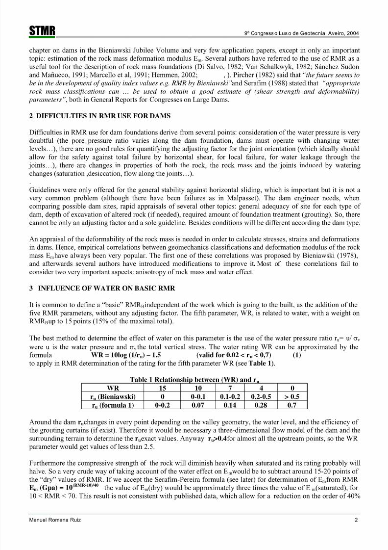
It is common to define a “basic” RMR B independent of the work which is going to the built, as the addition of thefive RMR parameters, without any adjusting factor. The fifth parameter, WR, is related to water, with a weight onRMR B up to 15 points (15% of the maximal total).
The best method to determine the effect of water on this parameter is the use of the water pressure ratio r u = u/ σv were u is the water pressure and σv the total vertical stress. The water rating WR can be approximated by theformula WR = 10log (1/ru) – 1.5 (valid for 0.02 < ru < 0,7) (1) to apply in RMR determination of the rating for the fifth parameter WR (see Table 1).
Table 1 Relationship between (WR) and ru
WR 15 10 7 4 0
ru (Bieniawski) 0 0-0.1 0.1-0.2 0.2-0.5 > 0.5
ru (formula 1) 0-0.2 0.07 0.14 0.28 0.7
Around the dam ru changes in every point depending on the valley geometry, the water level, and the efficiency ofthe grouting curtains (if exist). Therefore it would be necessary a three-dimensional flow model of the dam and thesurrounding terrain to determine the ru exact values. Anyway ru>0.4 for almost all the upstream points, so the WR parameter would get values of less than 2.5.
Furthermore the compressive strength of the rock will diminish heavily when saturated and its rating probably willhalve. So a very crude way of taking account of the water effect on E m would be to subtract around 15-20 points of
the “dry” values of RMR. If we accept the Serafim-Pereira formula (see later) for determination of Em from RMREm (Gpa) = 10(RMR-10)/40
the value of Em (dry) would be approximately three times the value of E m (saturated), for10 < RMR < 70. This result is not consistent with published data, which allow for a reduction on the order of 40%
8/13/2019 STMR Art DMRDamsFoundations
http://slidepdf.com/reader/full/stmr-art-dmrdamsfoundations 3/12
STMR 9º Congresso Luso de Geotecnia. Aveiro, 2004
Manuel Romana Ruiz 3
for Em when saturated. Therefore a rule of thumb could be to subtract 10 points of RMR (dry) to obtain E n (water).It is interesting to note that this is congruent with prior versions of RMR (before the 1989 version which actuallyhas become the “standard” one), and it is also the preferred method in Hoek’s GSI index practice.
Anyway it seems that the water consideration is a serious handicap not only for the accurate determination of Em bycorrelations with RMR, but also for the use itself of RMR in dams.
Hoek has advocated, speaking on the Hoek-Brown criteria, the use of a “dry RMR”, obtained with the maximalrating of the water parameter, with simultaneous introduction of real pore pressures in the computations (see forinstance the last version – “2002 edition”- in Hoek et al, 2002). No doubt that this is a sound procedure, whencomputing, and could be extended when dealing with geomechanics classification work in the upstream zone wherethe dam where pore pressures will be high.
We will define then a “basic dry RMR”: RMRBD as the addition of the first four parameters of RMR plus 15:1) Compressive strength, tested in water conditions similar to the future ones, e.g. saturated when the rock is going
to be saturated, and with the same ph of water.2) RQD of the rock mass
3) Joint spacing of the significative governing joint(s).4) Conditions of the significative governing joint(s).5) Water rating WR, always 15 (as if dry)
4 STABILITY OF DAMS AGAINST SLIDING
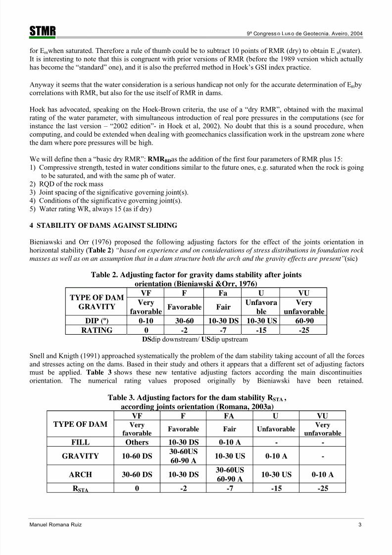
Bieniawski and Orr (1976) proposed the following adjusting factors for the effect of the joints orientation inhorizontal stability (Table 2) “based on experience and on considerations of stress distributions in foundation rock
masses as well as on an assumption that in a dam structure both the arch and the gravity effects are present” (sic)
Table 2. Adjusting factor for gravity dams stability after joints
orientation (Bieniawski &Orr, 1976)
VF F Fa U VUTYPE OF DAM
GRAVITYVery
favorableFavorable Fair
Unfavora
ble
Very
unfavorable
DIP (º) 0-10 30-60 10-30 DS 10-30 US 60-90
RATING 0 -2 -7 -15 -25DS dip downstream/ US dip upstream
Snell and Knigth (1991) approached systematically the problem of the dam stability taking account of all the forcesand stresses acting on the dams. Based in their study and others it appears that a different set of adjusting factorsmust be applied. Table 3 shows these new tentative adjusting factors according the main discontinuitiesorientation. The numerical rating values proposed originally by Bieniawski have been retained.
Table 3. Adjusting factors for the dam stability RSTA ,
according joints orientation (Romana, 2003a)
VF F FA U VUTYPE OF DAM Very
favorableFavorable Fair Unfavorable
Very
unfavorable
FILL Others 10-30 DS 0-10 A - -
GRAVITY 10-60 DS30-60US
60-90 A10-30 US 0-10 A -
ARCH 30-60 DS 10-30 DS30-60US
60-90 A10-30 US 0-10 A
RSTA 0 -2 -7 -15 -25
8/13/2019 STMR Art DMRDamsFoundations
http://slidepdf.com/reader/full/stmr-art-dmrdamsfoundations 4/12
STMR 9º Congresso Luso de Geotecnia. Aveiro, 2004
Manuel Romana Ruiz 4
DS dip downstream/ US dip upstream/ A any dip Gravity dams include CVC (Conventional vibrated concrete) andRCC (Roller compacted concrete), and hardfill concrete damsWhen the dip direction of the significative joint is not almost parallel to the downstream-upstream axis of the damthe danger of sliding diminishes due to the geometrical difficulties to slide. It is possible to take account of thiseffect multiplying the rating of the adjusting factor for dam stability R STA , by a geometric correction factor CF CF=(1-sin | d - j|)
2 where d is the direction upstream-downstream of the dam axis and j is the dip direction ofthe significative governing joint. The value of DMRSTA (related to the dam stability against sliding) is:
DMRSTA = RMRBD + CF x RSTA (2)
where RMRBD (“basic dry RMR”) is the addition of the RMR first four parameters plus a water rating of 15 andRSTA is the adjusting factor for dam stability ( Table 3).
Actually there are no data allowing to establish a correlation between the value of DMR STA and the degree of safetyof the dam against sliding. As a rule of thumb we can suggest:
DMRSTA > 60 No primary concern
60 > DMRSTA>30 Concern
30 > DMRSTA Serious concern These cannot be taken at all as numerical statements, but only as danger signals for the designer. Dam stability
must always and in any case be checked by the designer taking account of the probable distribution of water pore pressure across the dam foundation and of the mobilized shear strength of the significative joints. About thisquestion the Spanish National Committee on Large Dams states that “The study of the dam safety against sliding
requires a knowledge of the strength of the rock mass. The simple correlations between geomechanics
classifications and rock mass strength are not well established for dam foundations” (SCOLD, 1999).
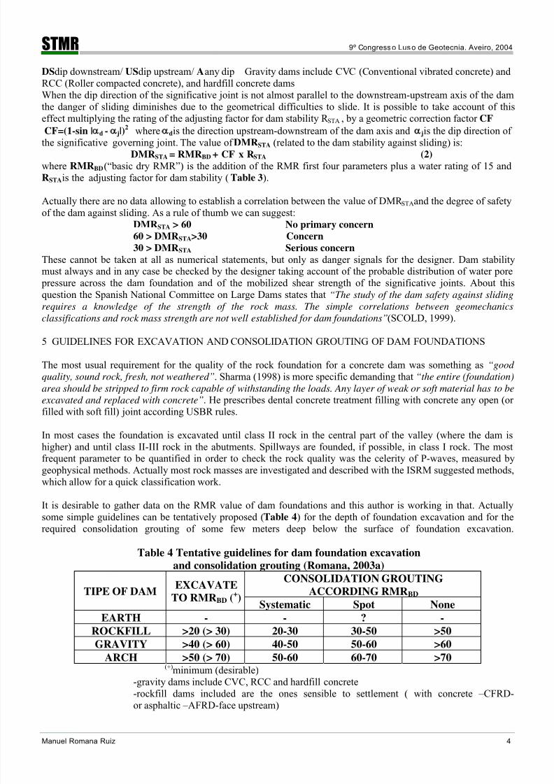
5 GUIDELINES FOR EXCAVATION AND CONSOLIDATION GROUTING OF DAM FOUNDATIONS
The most usual requirement for the quality of the rock foundation for a concrete dam was something as “good
quality, sound rock, fresh, not weathered”. Sharma (1998) is more specific demanding that “the entire (foundation)
area should be stripped to firm rock capable of withstanding the loads. Any layer of weak or soft material has to be
excavated and replaced with concrete”. He prescribes dental concrete treatment filling with concrete any open (or
filled with soft fill) joint according USBR rules.
In most cases the foundation is excavated until class II rock in the central part of the valley (where the dam ishigher) and until class II-III rock in the abutments. Spillways are founded, if possible, in class I rock. The mostfrequent parameter to be quantified in order to check the rock quality was the celerity of P-waves, measured bygeophysical methods. Actually most rock masses are investigated and described with the ISRM suggested methods,which allow for a quick classification work.
It is desirable to gather data on the RMR value of dam foundations and this author is working in that. Actuallysome simple guidelines can be tentatively proposed (Table 4) for the depth of foundation excavation and for therequired consolidation grouting of some few meters deep below the surface of foundation excavation.
Table 4 Tentative guidelines for dam foundation excavationand consolidation grouting (Romana, 2003a)
CONSOLIDATION GROUTING
ACCORDING RMRBD TIPE OF DAMEXCAVATE
TO RMRBD (+)
Systematic Spot None
EARTH - - ? -
ROCKFILL >20 (> 30) 20-30 30-50 >50
GRAVITY >40 (> 60) 40-50 50-60 >60
ARCH >50 (> 70) 50-60 60-70 >70(+) minimum (desirable)
-gravity dams include CVC, RCC and hardfill concrete-rockfill dams included are the ones sensible to settlement ( with concrete –CFRD-or asphaltic –AFRD-face upstream)

8/13/2019 STMR Art DMRDamsFoundations
http://slidepdf.com/reader/full/stmr-art-dmrdamsfoundations 5/12
STMR 9º Congresso Luso de Geotecnia. Aveiro, 2004
Manuel Romana Ruiz 5
6 CORRELATION BETWEEN EM AND RMR
6.1 General
Em modulus can have very different values depending on the direction of the principal stress. In stratified rock
mass, and/or with a governing joint orientation, the equivalent elastic modulus of deformation is the weightedarithmetic mean of the deformation modulus of the strata (when the stress is parallel to them), and the weightedharmonic mean (when the stress is perpendicular to them).
Therefore the perpendicular deformation modulus is always the minimal one and the parallel deformation modulusis always the maximal one. The difference between both of them gets wider as anisotropy of the rock massincreases. Barton (1983) proposed the following formulae:
Emin = 0.4 Emean , Emax = 1.6 Emean
and therefore (Emax - Emin) / Emean = 1.2.
This implies a relationship of 4 between maximal and minimal values of deformation modulus, which, according to
Barton, is confirmed by other data published by Rocha (1964) and Bieniawski (1978), and is probably adequate forrock masses very anisotropic and/or very bedded. In homogeneous rock masses, however, the relationship betweenmaximal and minimal values of the deformation modulus is smaller. Many authors have published data gatheredfrom in situ tests (Table 5). In all the cases the RMR value to be applied is the basic one without the adjustingfactor for the joints orientation proposed by Bieniawski for foundations. However, the variation of the modulusvalue according to direction of the principal stress suggests that it would be useful to apply some adjusting factor.
Table 5. Some data from in situ tests on relation Emax / Emin
SITE ROCKMASS Emax /Emin REFERENCE
Colbun plant Andesite 1,4 Van Sint (1993)
Marl 1,3Ridracoli dam
Sandstone 1,4Oberti et al (1986)
Sandstone 1,3Tamzaourt dam
Siltstone 1,9Jaoui et al (1982)
Water also reduces both the strength and the equivalent deformation modulus when the rock mass is saturated, avery important effect in dam foundations. The first papers neglected this water effect. The introduction of GSI (byHoek) included a very simple way to consider the water effect: to evaluate RMR as if the rock mass were fully dry(with a value for the water parameter WR of 15) and to introduce water pore pressure in computations (see
Bieniawski 2000). But that implies that neither the strength, nor the deformation modulus of the rock masschanges, and this hypothesis doesn’t take account of the reduction of the strength and the deformability of the rockmass when saturated.
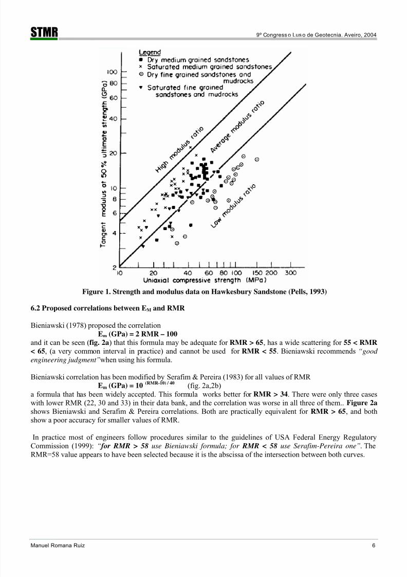
Figure 1 (Pells, 1993) shows a Deere-Miller diagram containing data from compression tests (failure strength anddeformation modulus at 50% of failure strength) in dry and saturated Hawkesbury sandstone. Saturation implies areduction almost proportional in both parameters, but the relationship between them would remain approximatelyconstant.
8/13/2019 STMR Art DMRDamsFoundations
http://slidepdf.com/reader/full/stmr-art-dmrdamsfoundations 6/12
STMR 9º Congresso Luso de Geotecnia. Aveiro, 2004
Manuel Romana Ruiz 6
Figure 1. Strength and modulus data on Hawkesbury Sandstone (Pells, 1993)
6.2 Proposed correlations between EM and RMR
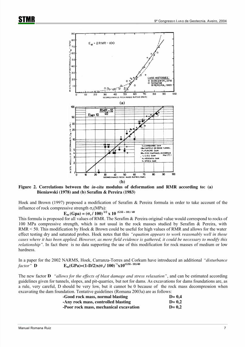
Bieniawski (1978) proposed the correlationEm (GPa) = 2 RMR – 100
and it can be seen (fig. 2a) that this formula may be adequate for RMR > 65, has a wide scattering for 55 < RMR
< 65, (a very common interval in practice) and cannot be used for RMR < 55. Bieniawski recommends “good
engineering judgment” when using his formula.
Bieniawski correlation has been modified by Serafim & Pereira (1983) for all values of RMREm (GPa) = 10
(RMR-10) / 40 (fig. 2a,2b)
a formula that has been widely accepted. This formula works better for RMR > 34. There were only three cases
with lower RMR (22, 30 and 33) in their data bank, and the correlation was worse in all three of them.. Figure 2a shows Bieniawski and Serafim & Pereira correlations. Both are practically equivalent for RMR > 65, and bothshow a poor accuracy for smaller values of RMR.
In practice most of engineers follow procedures similar to the guidelines of USA Federal Energy RegulatoryCommission (1999): “ for RMR > 58 use Bieniawski formula; for RMR < 58 use Serafim-Pereira one”. TheRMR=58 value appears to have been selected because it is the abscissa of the intersection between both curves.
8/13/2019 STMR Art DMRDamsFoundations
http://slidepdf.com/reader/full/stmr-art-dmrdamsfoundations 7/12
STMR 9º Congresso Luso de Geotecnia. Aveiro, 2004
Manuel Romana Ruiz 7
(a)
(b)Figure 2. Correlations between the in-situ modulus of deformation and RMR according to: (a)
Bieniawski (1978) and (b) Serafim & Pereira (1983)
Hoek and Brown (1997) proposed a modification of Serafim & Pereira formula in order to take account of theinfluence of rock compressive strength σc (MPa):
Em (Gpa) = ( c / 100) 1/2
x 10(GSI – 10) / 40
This formula is proposed for all values of RMR. The Serafim & Pereira original value would correspond to rocks of100 MPa compressive strength, which is not usual in the rock masses studied by Serafim & Pereira, withRMR < 50. This modification by Hoek & Brown could be useful for high values of RMR and allows for the watereffect testing dry and saturated probes. Hoek notes that this “equation appears to work reasonably well in those
cases where it has been applied. However, as more field evidence is gathered, it could be necessary to modify this
relationship”. In fact there is no data supporting the use of this modification for rock masses of medium or lowhardness.
In a paper for the 2002 NARMS, Hoek, Carranza-Torres and Corkum have introduced an additional “disturbance
factor” D Em(GPa)=(1-D/2)x( c / 100) ½
x10(GSI– 10)/40
The new factor D “allows for the effects of blast damage and stress relaxation”, and can be estimated accordingguidelines given for tunnels, slopes, and pit-quarries, but not for dams. As excavations for dams foundations are, asa rule, very careful, D should be very low, but it cannot be 0 because of the rock mass decompression whenexcavating the dam foundation. Tentative guidelines (Romana 2003a) are as follows:
-Good rock mass, normal blasting D= 0,4
-Any rock mass, controlled blasting D= 0,2-Poor rock mass, mechanical excavation D= 0,2
8/13/2019 STMR Art DMRDamsFoundations
http://slidepdf.com/reader/full/stmr-art-dmrdamsfoundations 8/12
STMR 9º Congresso Luso de Geotecnia. Aveiro, 2004
Manuel Romana Ruiz 8
6.3 Recommended formulae
With the published data there is only actual basis for the following recommendations:-RMRBD > 60 Use Bieniawski formula
-60 > RMRBD > 35 Use Serafim & Pereira original formula.
-35> RMRBD No formula is sure. Use as a guess Serafim & Pereira one
There are no data supporting normalized Hoek variations of Serafim & Pereira formula. The results obtained whenapplied to good-medium quality rock masses (e.g. RMR class II-III) with medium hard rocks (e.g. c =50 MPa) arenot consistent with the published data on Em.
6.4 Effect of anisotropy on Em
Em depends on the anisotropy of the rock mass and the maximum stress direction. It is possible to take account ofthis effect with the following rules of thumb:
-In very anisotropic rock masses Emax /Emin = 4.
You can add 8 to RMRB to obtain Emax and subtract 16 to RMRB to obtain Emin.
-In slightly anisotropic rock masses Emax
/Emin
is in the order of 1.4.
You can add 2 to RMRB to obtain Emax and subtract 1.4 to obtain Emin.
Such values are only approximate but can be useful when making sensitivity analysis of dam – foundation stressfields to get something similar to extreme situations. The best solution would be to apply some correction factordepending on the orientation of the joint(s) which define the more competent “strata” in the rock mass
6.5 Effect of water on Em
The effect of water on Em has been already discussed. There are no published data and most of authors used thesame value of Em before and after impounding the dam. The most frequently used WR (water rating) were 7 and/or10 reflecting a certain aim for compromise between WR = 15 (dry, r u = 0) and WR = 0 (fully saturated, r u > 0.5).
The above proposed rule of thumb (to subtract 10 from RMR B to get E m saturated, when using Serafim & Pereiraformula) is only a guess.
7 INFLUENCE OF THE FOUNDATION DEFORMABILITY ON THE DAM BEHAVIOR
7.1 General
There is a general agreement between dam engineers on the fact that two cases are dangerous for the normal behavior of a concrete dam: if Em varies widely across dam foundation, or if E c/Em reaches certain values (E c beingthe deformation modulus of concrete). Rocha (1964) established the most followed rule for arch dams (Table 6) ina paper which has become a “classic” reference for dam designers.
Table 6 Effect of Ec /Em on arch dam behavior(Rocha, 1964)Ec /Em Influence on dam Problems
< 1
1-4
4-8
8-16
> 16
Negligible
Low importance
Important
Very important
Special measures
None
None
Some
Serious
Very dangerous
Ec /Em < 4 allows for an easy behavior (and “high cost tests in the foundation exploration could be dispensed with”according Oliveira, 1990). The minimal sure (but with problems) value of Em for an arch dam would be around5GPa. The reported cases of arch dams founded in rock masses with Em<5GPa show serious problems (cracking
included) because of the low value of Em.

8/13/2019 STMR Art DMRDamsFoundations
http://slidepdf.com/reader/full/stmr-art-dmrdamsfoundations 9/12
STMR 9º Congresso Luso de Geotecnia. Aveiro, 2004
Manuel Romana Ruiz 9
Rocha et all (1974) presented data on the Alto Rabagao dam “built in a very deformable foundation”, with amodulus relationship Ec /Em of 20 above elevation 830 (maximum water level 880). “Tensile stresses (were
displayed)…in some points near the foundation downstream in the left bank. (As) these tensile stresses (were)
specially relevant…it was recommended …reinforcement parallel to the downstream face and …to the ground”
Silveira et all (1991) in a paper with the title “Influence of foundation heterogeneity on safety of arch dams” whichwas presented at 17th ICOLD Congress in Vienna analyzed the stresses in several built arch dams with verydifferent values of Ec/Em both in the after-construction state and the predicable aged state after many years. Theirconclusions were that “this influence (of the heterogeneity of foundation deformability) on the behavior of arch
dams for ordinary scenarios is (well) summarized (in Rocha table) and only for large heterogeneities this influence
is remarkable for arch dams”, “the heterogeneity of foundation decreases the safety factor and thus the capability
of the dam to resist to ageing. However….this reduction is only remarkable for larger heterogeneities”
In later papers Rocha (1975, 1976) extended his work to gravity dams. Ec /Em < 8 would be safe and Ec /Em > 16 would get to moderate to big problems. The existence of joints in concrete dams helps to cope with relativedeformability problems. This may be the main reason in the changes in the design of RCC concrete dams, from thefirst dams with almost no joints to the actual standards. Nevertheless RCC concrete gravity dams are less prone to
problems than CVC concrete dams due to the lesser value of Ec.
7.2 Value of Ec in CVC and RCC concrete
Andriolo (1995) gave a detailed report comparing properties of CVC and RCC concrete. Fig. 3 shows the data onEc from 5 CVC dams and 13 RCC dams. The mean data gives relationships of:
ERCC = 0.40 E CVC (at 7 -28 days)ERCC = 0.55 E CVC (at 90 days)
At 90 days ECVC varies between 28 Gpa and 51 Gpa with a mean value of 39 Gpa, whereas E RCC varies between 11GPa and 32 GPa with a mean value of 22 GPa. There is a great variation, depending on the cementitious materialcontent, but we can assume for CVC ECVC = 30/36 GPa , and for RCC ERCC = 20 GPa (less in many cases).
Fig. 3. Modulus of elasticity values from RCC and CVC concrete in dams (Andriolo,1995)
7.3 Value of Ehard in hardfill dams

8/13/2019 STMR Art DMRDamsFoundations
http://slidepdf.com/reader/full/stmr-art-dmrdamsfoundations 10/12
STMR 9º Congresso Luso de Geotecnia. Aveiro, 2004
Manuel Romana Ruiz 10
There are only very few hardfill dams already built. However ICOLD, in his Bulletin on the State of Art of RCCdams (2000), proposes Ehard = 10 GPa, (or less), for a paste with compressive strength of 9 MPa, values which arecongruent with the data from the Lower Monción Dam, built with hardfill and already in operation, (Capote et al,2003), and will be used in DMR method until more data can be gathered.
The same Ec value can be adopted for the revision of old dams, built with poor concrete of low strength, and / ordeteriorated by ageing.
7.4 Guidelines for DMRDEF
Zeballos and Soriano (1993) have published the results of Zeballos Ph. D. thesis (Polytechnic University ofMadrid), an extensive and intensive study on the effects of Ec/Em value on gravity and arch dams Table 7 (gatheredusing their data and others) shows the different ranges of RMR DEF related to the different ranges of possible problems in the dam due to the differences of deformability between the dam and his foundation.
DMR DEF (RMR related to deformability by the Serafim & Pereira formula)) depends on E m (when the rock mass is
saturated) and can be estimated with WR = 5 (a mean value which correspond to a nominal mean value ofr u = 0.25)
Table 7. Deformability problems in concrete dams according value of DMRDEF
(modified from Romana 2003)
DAM
Ec (GPa)
HEIGHT
(m)Normal Problems
Serious
problems
Arch
36 GPa
< 100
100-150
150-200
>50
>65
>75
40-50
50-65
60-75
<40
<50
<60
Gravity
CVC30 GPa
< 50
50-100100-150
>40
>50>60
25-40
40-5050-60
<25
<40<50
Gravity
RCC
20 GPa
< 50
50-100
>100
>35
>45
>55
20-35
35-45
45-55
<20
<35
<45
Hardfill
10 GPa
<50
50-100
>30
>40
15-30
30-40
<15
<30
8 USE OF DMR IN THE APPRAISAL OF SAFETY CONDITIONS IN OLD DAMS
At this moment a big number of old dams are in operation. Many were built before rock mechanics beginning(during the 1950-1960 decade) and were designed based only in the good engineering sense and experience of thedesigners (engineers and geologists). The existing information on the foundation conditions is very scarce andnever is presented following the actual “good practice”, which has been developed in the last 30 years.
The analysis of the safety conditions of these old dams has become mandatory in all countries. The DMRgeomechanics classification is a good method to gather orderly sound geomechanics information about the rockmass foundation and allows for a preliminary appraisal of the “weak points”. The author has used the DMRgeomechanics classification, as a first tool in the safety analysis of four old (more than 50 years) gravity dams nearValencia (Balagueras, Regajo, Ulldecona and Valbona dams) with good results. All of them are in operation andshow no visible signs of serious damage, but the concrete quality varies from good one (Regajo dam) to very poor(Balagueras dam)
8/13/2019 STMR Art DMRDamsFoundations
http://slidepdf.com/reader/full/stmr-art-dmrdamsfoundations 11/12
STMR 9º Congresso Luso de Geotecnia. Aveiro, 2004
Manuel Romana Ruiz 11
9 FINAL REMARKS
This paper has been written in the first days of January 2004 and is based in two prior ones: Romana, 2003a(September), and Romana, 2003b (November). It presents the first results of a ongoing research. The author will begrateful to any contribution with data which confirm, or deny, these preliminary results [email protected]
10 REFERENCES
Andriolo F.R. (1995) “RCC properties”. Proc. Int. Symp. on Roller Compacted Concrete Dams. Santander Ed.IECA-CNEGP. Pp 3-26.
Barton N. (1983) “Application of Q-System and index test to estimate shear strength and deformability of rockmasses”. Int. Symp Engineering Geology and Underground Construction. Lisbon. Theme II. Panel report. Vol.II, pp II. 51-II. 70.
Benitez E. (2003) “Personal communication”Bieniawski Z.T. (1978) “Determining rock mass deformability. Experience from case histories”. Int. J. of Rock
Mech and Min. Sci. Vol. 15 pp 237-242.Bieniawski Z.T. (1979) “Tunnel design by rock mass classifications”. U.S. Corp of Eng. Technical Report GL-799-
19. WES Vicksburg MS, pp 55-62 (reference in BIENIAWSKI, 1989, pp 128-130).
Bieniawski Z.T. (1989) “Engineering Rock Mass Classifications”. Ed WILEY. New York, 252 pp.Bieniawski Z.T.& Orr C.M. (1976). “Rapid site appraisal for dam foundation by geomechanics classification” 12 th
ICOLD. México. Q46. R32.Camargo P., Leite C.A., Bertin Neto S., Maldonado F.,& Cruz P.T. (1978) “Development of conceptual
geomechanics models for foundations of concrete dams. Approach applied to three projects”. Proc. Of ISRMInt. Symp. on rock mechanics related to dam foundations”. Ed. Kanji M.A. y Abrahao R.A. Ed. ABMS Pp II-57/II 64.
Capote A, Saenz F., & Mohedano V. (2003) “Contraembalse de Monción: a hardfill built in the DominicanRepublic”. Proc. Of the 4th Int Symp on RCC dams ( Ed Berga et al ) BALKEMA, pp 417-420.
Cruz P.T. “A busca de um metodo mais realista para analise de maciços rocosos como fundaçoes de barragems deconcreto” XI Seminario Nacional de Grandes Barragems, Fortaleza, Brazil (in portuguese).
Di Salvo C.A. (1982) “Geomechanics classification of the rock mass at Segunda Angostura dam”. 14 th ICOLDRio de Janeiro. Q53 R30.
Federal Energy Regulatory Commission (1999) “Engineering guidelines for the evaluation of hydropower projects.Chapter 11- Arch Dams”. Washington DC 20426. P 11-18
Hemmen (2002) “Paris dam” InternetHoek E. & Brown E.T. (1997) “Practical estimates of rock mass strength”. Int. J. of Rock Mech. and Min. Sci. Vol.
34, pp 1165-1186.Hoek E., Carranza-Torres E & Corkum B. (2002) “Hoek-Brown failure criterium-2002 edition”. NARMS. Toronto.Itaipú Binacional (1976) “Relatorio nº 2080-50-5000P-ROA” Reference in Camargo et al (1978) (in Portuguese).ICOLD (2000) “State-of-the-art of RCC dams”. Publication 75. ParisJaoui A., Islah M:, Garnier C., Gavard M. & Gily B. (1982) “The Tamzaourt dam. A buttress dam with particular
foundation problems” 14th ICOLD. Rio de Janeiro. Q 53, R 2.
John K. (1978) General Report on Characterization, properties and classifications of rock masses for damfoundations” Proc. of ISRM Int. Symp. on rock mechanics related to dam foundations”. Ed. Kanji M.A. yAbrahao R.A. Ed. ABMS. Pp II-1/II-12.
Marcello A., Eusepi G, Olivero S, Di Bacco R. (1991) “Ravanasella dam on difficult foundation” 17 th ICOLD.Vienna Q 66 R 21.
Oberti G., Bavestrallo F., Rossi P. & Flamigni F. (1986) “Rock Mechanic investigation, design and construction ofthe Ridracoli dam” .Rock Mechanics and Rock Engineering XIX, 3, July-September, pp 113-142.
Oliveira R. (1990) “Probabilistic approach to the assessment of foundation properties”. Proc. Int. Workshop on archdams. Coimbra (1987). Ed. Balkema. Pp 314-319.
Pells P.J. (1993) “Uniaxial strength testing” in “Comprehensive rock engineering”. Ed. J. Hudson. Ed.PERGAMON. Vol. 3, p. 75.
Pircher W. (1982) “Influence of geology and geotecnic on the design of dams”. 14 th ICOLD Río de Janeiro Q53
General Report.
8/13/2019 STMR Art DMRDamsFoundations
http://slidepdf.com/reader/full/stmr-art-dmrdamsfoundations 12/12
STMR 9º Congresso Luso de Geotecnia. Aveiro, 2004
Manuel Romana Ruiz 12
Rocha M. (1964) “Statement of the physical problem of the arch dam”. Symp. On Theory of arch dams.Southampton.
Rocha M., Silveira A.F., Rodríguez O.V., Azevedo M.C. & Florentino C. (1974). “Behaviour of a large dam builton a very deformable foundation”. 10th ICOLD, Montreal.
Rocha M. (1975) “Alguns problemas relativos a Mecánica das Rochas dos materiais de baixa resistencia” 5ºCongreso Panamericano de Mecánica del Suelo e Ingeniería de Cimentaciones. Buenos Aires
Rocha M. (1976) “Alguns problemas relativos a Mecánica das Rochas dos materiais de baixa resistencia”Geotecnia. Revista de Sociedade Portuguesa de Geotecnia. Nº 18, Novembro-Dezembro. Pp 3-27 (in portuguese).
Romana M (2002) “Determination of deformation modulus of rock masses by means of geomechanicsclassifications”. EUROCK Symposium (Madeira island) Ed. Sociedade Portuguesa de Geotecnia.
Romana M. (2003a) “DMR (Dam Mass Rating). An adaptation of RMR geomechanics classification for use indam foundation”. Inst. Cong. on Rock Mechanics. (Technology roadmap for rock mechanics) South AfricanInst. Of Min and Met.
Romana M. (2003b) “DMR , a new geomechanics classification for use in dams foundations, adapted fromRMR”.4th International Symposium on Roller Compacted Concrete (RCC) Dams MADRID
Sánchez Sudon J.F. & Mañueco M.G. (1995) “The Cenza Dam” Proc. Int. Symp. on Roller Compacted concrete
dams. Santander. Ed. IECA-CNEGP. Pp 625-636.Serafim J.L. & Pereira J.P. (1983) “Considerations on the Geomechanical Classification of Bieniawski”. Int. Symp.Engineering Geology and Underground Construction. Lisbon. Theme II. Vol. 1, pp II.33 – II.42.
Serafim J.L. (1988) “General Report on new developments in the construction on concrete dams” 16 th ICOLD.San Francisco. Q 62. GR.
Silveira A.F., Pina C. A. B., Costa C. A. P., Teixeiro Direito F. (1991) “Influence of foundation heterogeneity onsafety of arch dams” 17th ICOLD Vienna
SCOLD (1999) “Guía técnica de seguridad de presas. 3. Estudios geológico-geotécnicos y prospección demateriales”. Ed. CNEGP (SCOLD) 287 pp (in spanish).
Snell & Knigth (1991) “Susceptibility of dams to failure by sliding on sub-foundation strata that dip upstream”. 17th ICOLD Vienna, Q66 R88.
Van Schalkwyk (1982) “Geology and selection of the type of dam in South Africa”. 14 th ICOLD. Río de
Janeiro.Q51. R 44Van Sint M.L. (1993) “Examples of rock engineering in Chile” in “Comprehensive rock engineering”. Ed. J.
Hudson. Ed. PERGAMON. Vol. 5, p 812.Zeballos M. & Soriano A. (1993). “Deformabilidad del cimiento de presas de fábrica”. IV Jornadas Españolas de
Presas. SCOLD (Spanish ICOLD). Murcia. Pp 323-337 (in Spanish).
DEFINITIONS
WR Rating of the fifth parameter (water) in RMRRMR B Basic RMR, with no adjusting factor for joints orientation.RMR BD Dry basic RMR, with no adjusting factor for joints orientation. WR = 15R STA Adjusting factor for joint orientation (dip) related to dam stability (Table 3)
CF Geometric correcting factor for relative orientation of joints and dam axis. CF=(1-sin|αd -α j|)2 αd Direction upstream-downstream of the dam axisα j Dip direction of the significative governing joint for dam stability.DMR STA DMR related to dam stability
DMR STA = RMR BD + CF x R STA
Em Deformation modulus of rock mass.Emax Maximal deformation modulus of rock mass.Emin Minimal deformation modulus of rock mass.
Ec Deformation modulus of concreteECVC Deformation modulus of conventional vibrated concreteERCC Deformation modulus of roller compacted concrete
Ehard Deformation modulus of hardfillDMR DEF RMR related to relative deformability, with WR = 5, and no adjusting factor for joints orientation.(Tab.7)