comfort range servicing manual v3 0613 - therapy … comfort range servicing instruction manual ......
TRANSCRIPT
Servicing Instructions
Therapy Equipment Comfort Range (“Entonox”)
Revision 3 : June 2013

CONTENTS
Section No. 1 Record of Permanent Revisions 2 Comfort Range Product Information 3 Annual Function Test Recommendations/Procedure 4 Strip Down Instructions
5 Reconditioning/Servicing/Replacement Arrangements
6 Exploded Drawing

Comfort Range Servicing Instruction Manual Page 1 of 1 Rev. 3 Section 1 June 2013
Record of Permanent Revisions Retain this record at the front of the Manual. On receipt of Revision, revise as detailed in the Letter of Transmittal and record the incorporation of the revision on this sheet.
Rev. No. Issue Date Date Inserted By

Comfort Range Servicing Instruction Manual Page 1 of 2 Rev. 3 Section 2 June 2013
Product Information – Comfort Range (“Entonox”)
Function
The function of the O2/N2O (“Entonox”) Demand Valve is to provide a patient operated device capable of supplying over 200 Litres per Minute of “Entonox” gas.
Mainly used in the Maternity Department, the Valve can be used wherever Analgesic gas is required i.e. Accident & Emergency, Fracture Clinic, Burns Unit etc. The unit should be operated and stored in a dry clean environment within the temperature
range of -10°C to +40°C. Types Comfort Range Kit - Pin Index O2/N2O (“Entonox”) Medireg & Schrader (From Cylinder) O2/N2O (“Entonox”) Demand Valve with 2M Hose & Probe Facemask & Mouthpiece Demand Valve Only - O2/N2O (“Entonox”) Demand Valve with 2M Hose & Probe Facemask & Mouthpiece Hose - PVC (Non-Autoclavable) and Silicone (Autoclavable) Hose is available Technical Specification
Regulator Inlet Connection - Pin Index Inlet Pressure - Up to 2000psi Outlet Pressure - Up to 6 Bar (Approx 90psi) Constitutional Materials - Brass Jet and Diaphragm Shaft PTFE Seating Nitrile and Viton O Rings Brass Main Body Polycarbonate Casing

Comfort Range Servicing Instruction Manual Page 2 of 2 Rev. 3 Section 2 June 2013
Plated Brass Bullnose Nipple/Handwheel Glass Filed Nylon Top Cover Plated Brass 3/8”BSP Outlet Stainless Steel Springs Demand Valve Inlet Connection - British Standard Probe Constitutional Materials - Polysulphone Body/Cap Plated Brass Housing Stainless Steel Trigger Glass Filed Nylon Seating Carrier PTFE Shaft and Seat Internal Viton and PTFE Coated O Rings Approval/Warranties/Servicing Requirements Regulator The Therapy Equipment Pipeline Suction range fully complies to the requirements of BS EN 738-1: 1997 (Pressure Regulators for use with Medical Gases) and is CE Marked in accordance with current European legislation. The Therapy Equipment Medireg range is supplied with a 4 Year Function Warranty. The Therapy Equipment Medireg range requires reconditioning every four years. During this process, all internal and external seals, and Seatings are replaced. Demand Valve The Therapy Equipment O2/N2O fully complies to the requirements of BS 4272: Part 2 (Anaesthetic and Analgesic Machines, Part 2: Specification for intermittent (demand) flow analgesic machines for use with 50/50% (V/V) nitrous oxide and oxygen) and CE Marked in accordance with current European legislation. The Therapy Equipment Demand Valve is supplied with a 3 Year Function Warranty The Demand Valve requires reconditioning every 3 years. During this process, the internal seats and seals are replaced. It is also recommended that the Hose Assembly (both PVC and Silicone) be replaced during the 3 year reconditioning.

Comfort Range Servicing Instruction Manual Page 1 of 3 Rev. 3 Section 3 June 2013
Annual Function Test Requirements
Regulator Frequency Annually or in accordance with the Hospital Policy Objective To replace all external seals and ensure that the unit is in an accurate working condition and leak free Precaution It is strongly advised that protective gloves be worn before any servicing is carried out on Medical Devices Procedure Static/Dynamic Pressure Test Procedure
1. Change Bodok Seal (6159) on Pin Index Yoke.
2. Connect the Regulator to the Cylinder, and hand tighten Yoke Screw on the Pin Index fitting.
3. Connect a Fine Adjustment Valve and 10 Bar Pressure Gauge, making sure that the
Fine Adjustment Valve is in the open position.
4. Turn the cylinder on slowly, and check the Dynamic Pressure (Flowing Pressure) i.e. with Fine Adjustment Valve is in the open position, and Static Pressure i.e. with Fine Adjustment Valve in the closed position.
Dynamic Pressure - 60-90psi Static Pressure - 60-90psi
5. Once settled, the needle should give a fixed reading – any movement in the needle either up or down, over a period of time signifies malfunction. Please remove the Regulator from use, if any malfunction noted.

Comfort Range Servicing Instruction Manual Page 2 of 3 Rev. 3 Section 3 June 2013
Leak Test Procedure
1. Ensure that the Schrader Outlet is occluded, and that there is no Probe fitted into it. 2. Connect the Regulator to the Cylinder, and hand tighten the Yoke Screw on the Pin
Index fitting.
3. Turn the cylinder on slowly. 4. Ensure that the gauge on the Regulator is registering the approximate contents of
the cylinder.
5. Turn the cylinder OFF, with the pressure retained within the Regulator, and leave for approximately 15-20 minutes.
6. Ensure that all possible outlets for the gas are turned off (or blocked), and that the
Gauge needle does not drop. A drop on the needle indicates a leak. If a leak is detected, then the unit should be removed from use, and reconditioned (or returned to Therapy Equipment under warranty if within 4 years old
Demand Valve Frequency Annually or in accordance with the Hospital Policy Objective To ensure that the unit is in a clean, accurate working condition and leak free Precaution It is strongly advised that protective gloves be worn before any servicing is carried out on Medical Devices Procedure
1. Connect the Demand Valve to a pressure source (either Gas Pipeline or O2/N2O Pin Index Medireg & Schrader)
2. In the case of units connected to a cylinder, ensure that the cylinder is ON and that
the Regulator gauge is registering a reading
3. Press the FLUSH Button in the centre of the Demand Valve Cap, and ensure that the unit is giving a large flow of gas.

Comfort Range Servicing Instruction Manual Page 3 of 3 Rev. 3 Section 3 June 2013
4. De-press the FLUSH Button, and ensure that there is no audible sound coming from the Demand Valve
5. Apply some leak detection fluid to both ends of the Hose Assembly and ensure that there are no leaks from either end of the Hose.
6. Apply a Function Check label, and record Serial Number, and location

Comfort Range Servicing Instruction Manual Page 1 of 5 Rev. 2 Section 4 October 2005
Strip Down Maintenance Instructions
Regulator Please follow the Medireg Reconditioning instructions, as outlined in the Medireg Servicing Instruction Manual. Care however should be exercised however in ensuring that the correct O2/N2O (“Entonox”) Regulator parts are used. The O2/N2O Pin Index Medireg Reconditioning Kit contains the following:
Part No Description O2/N2O P/I
6000-07 Diaphragm Assembly X
6159 Bodok Seal X
5005-22 Pin Index Yoke O Ring X
5005-05-02 Pin Index Year Label X
5099-18 Safety Valve O Ring X
5099-11 Small Jet O Ring X
5099-12 Large Jet O Ring X
5099-23 Serial Number Label X
Kit Price £21.25
Kit Part Number 6010-01
Should the Gauge or Jet Seating require replacement, the following parts should be obtained: O2/N2O (“Entonox”) Gauge - 6000-01 O2/N2O (“Entonox”) Jet Seating - 6000-03 Hose Assembly It is recommended that the Hose Assembly be replaced as part of the Demand Valve Service, every three years. Both types of Hose Assembly are supplied with a B.S. “Entonox” Probe, and Demand Valve Connection suitable for the Therapy Equipment Demand Valve. The length of Hose is 2 Metres as standard, however up to 4 Metres can be purchased. PVC Hose Assembly Complete - 6005-60 Silicone Hose Assembly Complete - 6005-50

Comfort Range Servicing Instruction Manual Page 2 of 5 Rev. 2 Section 4 October 2005
Demand Valve
Frequency The Demand Valve requires reconditioning every 3 Years. The Demand Valve is supplied with a 3 Year Function Warranty, and strip down maintenance on the product should not be required during this initial period. Any functional fault found within the first 3 Years of Purchase is covered under the Warranty, and the product should therefore be returned to the manufacturer for a warranty repair. The warranty does not however cover accidental damage. Objective To replace the Internal Valve Seating, and retest to ensure the unit is functioning correctly and leak free. Precaution It is strongly advised that protective gloves be worn before any servicing is carried out on Medical Devices Procedure
1. Using the special tool, unscrew and remove the Bonnet (6005-13)
2. Examine the Skid Ring (6005-12) – it should be suitable for re-use, subject to visible damage.
3. Visually inspect the Main Diaphragm (6005-14) for any flaws, or signs of
deterioration. If there are any doubts on the condition, replace the Diaphragm.
4. Loosen the two knurled rings (6005-28) and (6005-04). When both of the rings have been loosened, the Valve Housing can be moved, by pushing gently from the Hose Input end.
5. Once the housing has been moved, GENTLY remove the two ‘feet’ of the lever
(6005-18) from the Main Shaft (6005-19).
6. The opposite end of the hose input, is now to be removed. Using a special key, unscrew the End Cap (6005-07) and remove.
Comfort Range Servicing Instruction Manual Page 3 of 5 Rev. 2 Section 4 October 2005
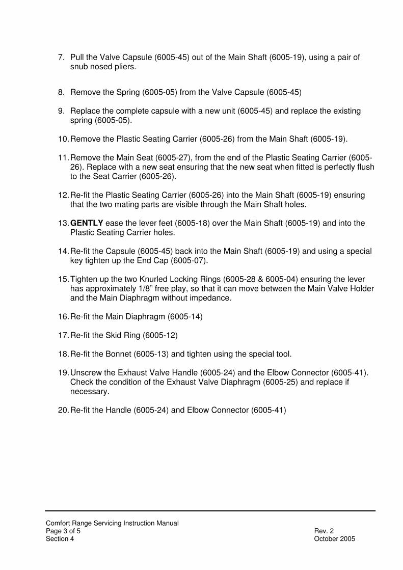
7. Pull the Valve Capsule (6005-45) out of the Main Shaft (6005-19), using a pair of snub nosed pliers.
8. Remove the Spring (6005-05) from the Valve Capsule (6005-45)
9. Replace the complete capsule with a new unit (6005-45) and replace the existing spring (6005-05).
10. Remove the Plastic Seating Carrier (6005-26) from the Main Shaft (6005-19).
11. Remove the Main Seat (6005-27), from the end of the Plastic Seating Carrier (6005-
26). Replace with a new seat ensuring that the new seat when fitted is perfectly flush to the Seat Carrier (6005-26).
12. Re-fit the Plastic Seating Carrier (6005-26) into the Main Shaft (6005-19) ensuring
that the two mating parts are visible through the Main Shaft holes.
13. GENTLY ease the lever feet (6005-18) over the Main Shaft (6005-19) and into the Plastic Seating Carrier holes.
14. Re-fit the Capsule (6005-45) back into the Main Shaft (6005-19) and using a special
key tighten up the End Cap (6005-07).
15. Tighten up the two Knurled Locking Rings (6005-28 & 6005-04) ensuring the lever has approximately 1/8” free play, so that it can move between the Main Valve Holder and the Main Diaphragm without impedance.
16. Re-fit the Main Diaphragm (6005-14)
17. Re-fit the Skid Ring (6005-12)
18. Re-fit the Bonnet (6005-13) and tighten using the special tool.
19. Unscrew the Exhaust Valve Handle (6005-24) and the Elbow Connector (6005-41).
Check the condition of the Exhaust Valve Diaphragm (6005-25) and replace if necessary.
20. Re-fit the Handle (6005-24) and Elbow Connector (6005-41)

Comfort Range Servicing Instruction Manual Page 4 of 5 Rev. 2 Section 4 October 2005
Testing
Test Equipment Required
1. Calibrated kPa/cmH2O Test gauge
2. Calibrated Flowmeter measuring in excess of 200 Litre per Minute
3. Lung Simulator Test Procedure
1. Connect the fully assembled Demand Valve to a Gas Source
2. Ensure there are no audible sounds of gas leakage
3. Press the Flush Button on the Bonnet to activate the ‘purge’ supply of gas
4. Ensure that the unit switches off when the Flush Button is released. If the initial tests reveal no problems:
5. Connect the unit to a Lung Simulator and Flowtube as outlined below, and measure the lift off pressure and flowrates.

Comfort Range Servicing Instruction Manual Page 5 of 5 Rev. 2 Section 4 October 2005
Test Results
The tests should be within the following:
• Negative Pressure less than -1.5kPa (-15cmH2O) at a flowrate of 200 LPM
• Negative Pressure less than -0.25kPa (-2.5cmH2O) at a flowrate of 10 LPM Both readings as per BS 4272: Part 2 (Anaesthetic and Analgesic Machines, Part 2: Specification for intermittent (demand) flow analgesic machines for use with 50/50% (V/V) nitrous oxide and oxygen)
• The flowrate reading after pushing the Flush Button should exceed 200 LPM , although the Exhaust Valve will require blocking off during this procedure.

Comfort Range Servicing Instruction Manual Page 1 of 1 Rev. 2 Section 5 October 2005
Reconditioning/Servicing/Replacement Arrangements
Reconditioning Whilst Therapy Equipment provide free of charge training (UK only) in the reconditioning and servicing of Comfort Range, we also provide a reconditioning service. The units will be fully reconditioned using our recommended procedure, and returned to the customer with a renewed Regulator four year function warranty and Demand Valve three year function warranty. Replacement We offer a discounted scheme whereby we exchange your old units for brand new units. Please see the catalogue for full details/pricing Servicing Kits Regulator
Part No Description Includes
6000-07 Diaphragm Assembly X
6159 Bodok Seal X
5005-22 Pin Index Yoke O Ring X
5005-05-02 Pin Index Year Label X
5099-18 Safety Valve O Ring X
5099-11 Small Jet O Ring X
5099-12 Large Jet O Ring X
5099-23 Serial Number Label X
Kit Part Number 6010-01
Demand Valve
Part No Description Includes
6005-27 Demand Valve Seating X
6005-46 Demand Valve Capsule X
Kit Part Number 6005-46
Comfort Range Servicing Instruction Manual Page 1 of 1 Rev. 2 Section 6 October 2005
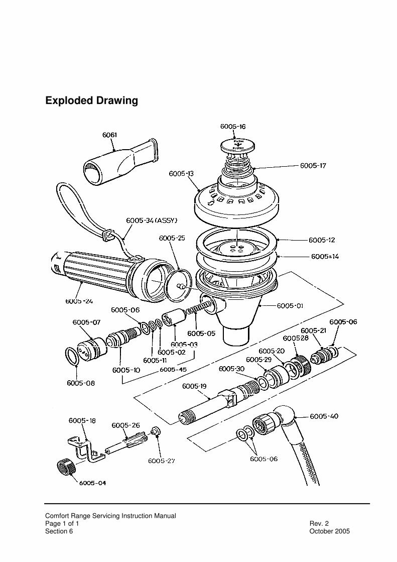
Exploded Drawing