collagen-based scaffolds for cornea tissue...
TRANSCRIPT
COLLAGEN-BASED SCAFFOLDS FOR CORNEA TISSUE ENGINEERING
A THESIS SUBMITTED TO THE GRADUATE SCHOOL OF NATURAL AND APPLIED SCIENCES
OF MIDDLE EAST TECHNICAL UNIVERSITY
BY
NİHAL ENGİN VRANA
IN PARTIAL FULFILLMENT OF THE REQUIREMENTS FOR
THE DEGREE OF MASTER OF SCIENCE IN
BIOTECHNOLOGY
SEPTEMBER 2006

Approval of the Graduate School of Natural and Applied Sciences
Prof. Dr. Canan Özgen Director
I certify that this thesis satisfies all the requirements as a thesis for the degree of Master of Science.
Prof. Dr. Fatih Yõldõz Head of Department
This is to certify that we have read this thesis and that in our opinion it is fully adequate, in scope and quality, as a thesis and for the degree of Master of Science.
Dr. David Stuart Hulmes
Co-Supervisor
Prof. Dr. Vasõf Hasõrcõ
Supervisor
Examining Committee Members
Prof. Dr. Meral Yücel (METU, BIOL)
Prof. Dr. Vasõf Hasõrcõ (METU, BIOL)
Prof. Dr. Mesude İşcan (METU, BIOL)
Prof. Dr. Kuyaş Buğra (BOUN, MOLGEN)
Assist. Prof. Ayşe Elif Erson (METU, BIOL)

iii
I hereby declare that all information in this document has been obtained and presented in accordance with academic rules and ethical conduct. I also declare that, as required by these rules and conduct, I have fully cited and referenced all material and results that are not original to this work. Name, Last name : Nihal Engin Vrana
Signature :
iv
ABSTRACT
COLLAGEN-BASED SCAFFOLDS FOR CORNEA TISSUE ENGINEERING
Vrana, Nihal Engin
M.S., Department of Biotechnology
Supervisor : Prof. Dr. Vasõf Hasõrcõ
Co-Supervisor : Dr. David Stuart Hulmes
September 2006, 87 pages
In this study, collagen based scaffolds were prepared for cornea tissue
engineering. Three different cell carriers (rat tail collagen foam, insoluble
collagen foam and patterned collagen film) were produced using two different
collagen sources. Scaffolds were designed to mimic the unique topographical
features of the corneal stroma. A novel crosslinking method was developed to
achieve constant foam thickness. All scaffolds were tested with the primary cells
of the native corneal stroma, human keratocytes. Although both foams promoted
cell growth and penetration, rat tail foams were found to be superior for
keratocyte proliferation. Their degradation rates were high enough but did not
compromise their structural integrity during testing. Transparency studies with
the foams revealed a progressive improvement. Collagen films degraded
significantly over a one month period; however, the presence of cells increased
the tensile strength of the films over a 21 day period to close to that of the
native cornea and compensated for the loss of strength due to degradation. The
micropatterned films proved to have higher transparency than the unpatterned
scaffolds. In this study, it was possible to prepare collagen based micropatterned
scaffolds using a silicon wafer and then a silicone template, successively, starting
from original designs. The resultant collagen films were able to control cell
growth through contact guidance, restricted cells and secreted-ECM within the
pattern grooves, resulting in a higher transparency in comparison to unpatterned

v
films. Thus, the tissue engineered constructs revealed a significant potential for
use as total artificial corneal substitutes.
Keywords: Tissue Engineering, Cornea, Micropatterning, Collagen, Contact
guidance
vi
ÖZ
KORNEA MÜHENDİSLİĞİ İÇİN KOLLAJEN TEMELLİ DOKU
MÜHENDİSLİĞİ İSKELELERİ
Vrana, Nihal Engin
Yüksek Lisans, Biyoteknoloji ABD
Tez Yöneticisi : Prof. Dr. Vasõf Hasõrcõ
Ortak Tez Yöneticisi : Dr. David Stuart Hulmes
Eylül 2006, 87 sayfa
Bu çalõşmada iki farklõ kollajen kaynağõ kullanõlarak farklõ kollajen temelli hücre
iskeleleri (taşõyõcõlarõ) (fare kuyruğu kollajen köpükler, çözünmeyen kollajen
köpükler ve mikrodesenli kollajen filmler), doku mühendisliği metodlarõyla yapay
kornea stromasõ geliştirilmesi amacõyla üretilmiştir. Bu hücre taşõyõcõlarõnõn
karakterizasyonlarõ yapõlmõş ve hepsi kornea stromasõnda bulunan keratositlerle,
in vitro koşullarda denenmiştir. Söz konusu hücre taşõyõcõlarõ, korneal stroma
yapõsõ ve stromanõn doğal yüzey özellikleri gözönüne alõnarak tasarlanmõşlardõr.
Fare kuyruğu kollajeni köpüklerinin sabit bir kalõnlõkta üretilmesi için yeni bir
çapraz bağlama metodu geliştirilmiştir. Her iki köpük tipi de hücre büyümesini ve
yayõlõmõnõ sağlamõştõr, ancak köpüklerin farklõ bozunma hõzlarõ ve fiziksel
yapõlarõndaki farklõlõklar keratositlerin farklõ büyüme davranõşlarõ göstermesini
sağlamõştõr. Fare kuyruğu kollajeni köpüklerinin hücre büyümesi açõsõndan daha
üstün olduklarõ saptanmõştõr. Her iki yapõda da õşõk geçirgenliği gelişmesi yavaş
olmaktadõr. Mikrodesenli kollajen filmler, yönelimli stroma yapõsõnõn taklit
edilmesinin sağlayacağõ avantajlarõ belirlemek amacõyla kullanõlmõştõr. Yüzey
desenleri hücrelerin ve hücre salgõlarõnõn ve aynõ zamanda hücre sitoiskeletinin
yönelimli olmalarõnõ sağlamõştõr. Yapõlan mekanik testler, 21 günlük bir zaman
aralõğõnda, keratosit varlõğõnõn filmlerin gücünü arttõrdõğõnõ göstermiş ve
biyobozunumun hücre büyümesi ve hücredõşõ matriks salgõlanmasõyla
karşõlandõğõnõ göstermiştir. Ayrõca õşõk geçirgenliği bakõmõndan desenli filmlerin
vii
desensiz filmlere göre daha iyi olduğu gözlemlenmiştir. Sonuç olarak, çalõşma
için tasarlanmõş desenlere sahip kollajen filmler başarõyla üretilmiş, bu filmlerin
hücreleri ve hücre salgõlarõnõ yüzey desenleri içine sõnõrladõğõ belirlenmiştir.
Desenlerin hücre varlõğõnda yapõnõn õşõk geçirgenliği üzerinde olumlu etkisi olduğu
saptanmõştõr. Elde edilen bilgilerle üretilen taşõyõcõlarõn kornea stromasõ hücrelerin
büyümesi ve bulunduklarõ çevreyi yeniden şekillendirmeleri açõsõndan uygun
olduğu ve tüm yapay kornea uygulamalarõnda başarõyla kullanõlabilecekleri
sonuçlarõna varõlmõştõr.
Anahtar Kelimeler: Doku Mühendisliği, Kornea, Kollajen, Mikrodesen, Temas
yönlendirimi

viii
To My Family
ix
ACKNOWLEDGEMENTS
I wish to express my sincere gratitude to my supervisor Prof. Dr. Vasõf
Hasõrcõ, for his continuous support, guidance and help throughout this study.
I would like to thank Dr. David Hulmes for his contributions to this study
both as my co-supervisor and Cornea Engineering project director.
I wish to thank Prof. Odile Damour and Nicolas Builles for supplying human
keratocytes and their hospitality during my insightful visit to Dr. Damour�s
laboratory.
I would like to thank to Dr. Ahmed El-Sheikh for our collaboration in
mechanical tests. It was a long and rigorous set of experiments which I am
grateful to have been involved in. I am also grateful for his help and hospitality
during a part of these experiments which I participated in his laboratory.
I am very grateful to Prof. Atilla Aydõnlõ for his help in the manufacturing of
patterned templates.
I would like to thank my labmates for their help, support and
understanding. Põnar Zorlutuna, Põnar Yõlgör, Buket Başmanav, Oya Tağõt, Deniz
Yücel, Halime Kenar, Nihan Öztürk, Albana Ndreu, Erkin Aydõn and Dr. Mathilde
Hindie; they have all contributed to this study in one way or another.
I would also want to thank all the undergraduate students, especially
Hande Koçak and Pelin Gülay, who have worked with me. Their presence was
quite helpful.
I am grateful to Dr. Ayşen Tezcaner for her advices and contributions in the
initial phases of my study.
I am grateful to the EU FP6 Project �Cornea Engineering� through which
both I and the research was funded.
I would like to acknowledge METU Central Laboratory for analyses done in
their facilities.
I am also grateful to TÜBİTAK for their support through BİDEP 2210
Scholarship.
x
TABLE OF CONTENTS
PLAGIARISM DECLARATION ........................................................................iii
ABSTRACT ................................................................................................iv
ÖZ...........................................................................................................vi
DEDICATION........................................................................................... viii
ACKNOWLEDGEMENTS ...............................................................................ix
TABLE OF CONTENTS ................................................................................. x
LIST OF TABLES ......................................................................................xiv
LIST OF FIGURES ....................................................................................x v
NOMENCLATURE..................................................................................... xvii
CHAPTERS
1. INTRODUCTION..................................................................................... 1
1.1 Cornea............................................................................................. 1
1.1.1 Structure, Function and Composition of Cornea............................. 1
1.1.2 Structure and Properties of Corneal Stroma .................................. 3
1.1.3 Corneal Keratocytes................................................................... 5
1.1.4 Corneal Diseases and Dystrophies ............................................... 6
1.1.5 Remedies for Cornea Related Health Problems .............................. 7
1.2 Tissue Engineering ............................................................................ 8
1.2.1 Definition of Tissue Engineering................................................... 8
1.2.2 Cell Sources for Tissue Engineering............................................ 10
1.2.3 Tissue Engineering Scaffolds ..................................................... 10
1.2.4 Scaffold Manufacture Techniques............................................... 12
1.3 Contact Guidance............................................................................ 15
1.3.1 Definition of Contact Guidance .................................................. 15
xi
1.3.2 Methods for Micro and Nanopatterning ....................................... 16
1.4 Collagen......................................................................................... 18
1.4.1 Properties of Collagen .............................................................. 18
1.4.2 Structure of Collagen ............................................................... 18
1.4.3 Function of Collagen ................................................................ 19
1.4.4 Use of Collagen in Tissue Engineering ........................................ 19
1.4.5 Tissue Engineering Approaches for Cornea.................................. 21
2. MATERIALS AND METHODS................................................................... 23
2.1 Materials........................................................................................ 23
2.1.2 Cells ...................................................................................... 24
2.2 Methods......................................................................................... 24
2.2.1 Template Preparation............................................................... 24
2.2.2 Collagen Film Production .......................................................... 25
2.2.2.1 Micropatterned Collagen Film Production............................. 25
2.2.2.2 Unpatterned Collagen Film Production ................................ 25
2.2.3 Collagen Foam Production ........................................................ 26
2.2.3.1 Foam Production from Insoluble Collagen............................ 26
2.2.3.2 Production of Collagen Foam from Rat Tail .......................... 26
2.2.3.2.1 Uncrosslinked Foam Production.................................... 26
2.2.3.2.2 Pre-Crosslinked Foam Production ................................. 26
2.2.4 Scaffold Stabilization................................................................. 26
2.2.5 Scaffold Characterization........................................................... 27
2.2.5.1 Film and Foam Thickness Measurement .............................. 27
2.2.5.2 Measurement of Surface Porosity of Foams ......................... 27
2.2.5.3 Bulk Porosity of Foams ..................................................... 27
2.2.5.4 Pore Size Distribution ....................................................... 27
2.2.5.5 Degradation in situ .......................................................... 28

xii
2.2.5.6 Stability of the Films: Collagenase Assay ............................ 28
2.2.6 SEM Examination...................................................................... 28
2.2.7 In vitro Studies ........................................................................ 28
2.2.7.1 Cell Culture ..................................................................... 28
2.2.7.1.1 Keratocyte Culture ..................................................... 29
2.2.7.1.2 D407 Culture............................................................. 29
2.2.7.2 Cell Seeding onto Scaffolds ............................................... 29
2.2.7.3 Cell Proliferation on Scaffolds ............................................ 29
2.2.8 Microscopy Studies ................................................................... 30
2.2.8.1 Acridine Orange Staining................................................... 30
2.2.8.2 DAPI Staining.................................................................. 30
2.2.8.3 SEM Examination ............................................................. 30
2.2.8.4 FITC-Labelled Phalloidin Staining ....................................... 31
2.2.8.5 Immunostaining............................................................... 31
2.2.8.5.1 Collagen Type I Staining ............................................. 31
2.2.8.5.2 Keratan Sulfate Staining ............................................. 31
2.2.8.6 Confocal Laser Scanning Microscopy (CLSM)......................... 32
2.2.9 Mechanical Strength of Patterned Collagen Films ......................... 32
2.2.10 Transparency Measurements................................................... 32
2.3 Statistical Analysis.......................................................................... 33
3. RESULTS and DISCUSSION................................................................... 34
3.1 Scaffold Characterization................................................................. 34
3.1.1 Film Characterization ............................................................... 34
3.1.2 Foam Characterization ............................................................. 36
3.1.2.1 Crosslinking .................................................................... 36
3.1.2.2 Surface Porosity............................................................... 37
3.1.2.3 Porosity of the foams........................................................ 38
xiii
3.1.2.4 Pore Size Distribution ....................................................... 39
3.2 Degradation Profiles of the Scaffolds................................................. 41
3.2.1 Collagenase Susceptibility of Rat Tail Collagen Films .................... 46
3.3 Cell Proliferation............................................................................. 47
3.4 Microscopy Studies......................................................................... 49
3.4.1 Cell Morphology....................................................................... 49
3.4.2 Phalloidin Staining ................................................................... 55
3.4.3 Immunostaining ...................................................................... 55
3.4.3.1 Collagen Type I Staining ................................................... 55
3.4.3.2 Keratan Sulfate Staining ................................................... 57
3.4.4 Confocal Microscopy (CLSM) ..................................................... 58
3.5 Mechanical tests............................................................................. 61
3.6 Transparency Measurements ........................................................... 64
4. CONCLUSION ...................................................................................... 68
REFERENCES........................................................................................... 72
APPENDICES ........................................................................................... 87
xiv
LIST OF TABLES
Table 2.1 Template dimensions ................................................................. 24
Table 3.1 Foam thickness before and after crosslinking................................. 37
Table 3.2 Surface porosity of foams ........................................................... 38
Table 3.3 Bulk porosity of the foams .......................................................... 38
Table 3.4 Average pore size of rat tail and insoluble collagen foams............... 41
Table 3.5 Transparency of foams ............................................................... 67
xv
LIST OF FIGURES
Figure 1.1 Structure of the cornea and its components .................................. 1
Figure 1.2 Distribution of cells within the cornea............................................ 2
Figure 1.3 Parallel orientation of collagen fibrils ............................................. 3
Figure 1.4 Perpendicular orientation of lamellae in corneal stroma ................... 4
Figure 1.5 A general scheme of tissue engineering methodology...................... 9
Figure 1.6 Porous scaffolds ....................................................................... 14
Figure 1.7 Schematic representation of the photolithography technique.......... 17
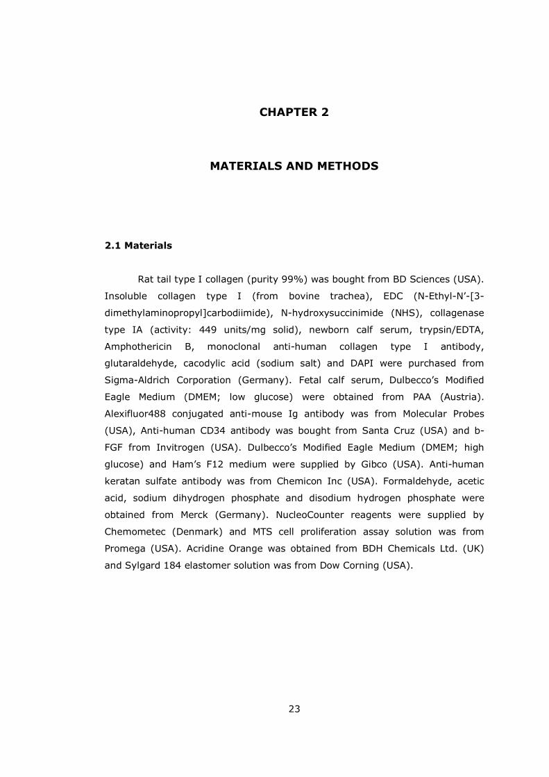
Figure 2.1 Macroscopic appearance of the elastomer template....................... 25
Figure 3.1 Stereomicrographs of patterned collagen films ............................. 34
Figure 3.2 SEM micrographs of a crosslinked, patterned collagen film............. 35
Figure 3.3 Effect of conventional crosslinking on rat tail collagen foams.......... 36
Figure 3.4 Structure of pre-crosslinked collagen foam .................................. 37
Figure 3.5 Pore size distribution................................................................. 40
Figure 3.6 Weight loss of collagen scaffolds over the course of 4 weeks.......... 42
Figure 3.7 pH change of the degradation medium ........................................ 42
Figure 3.8 Micrographs of collagen films before and after degradation ............ 43
Figure 3.9 SEM micrographs of rat tail collagen foam. .................................. 44
Figure 3.10 SEM micrographs of insoluble collagen foams............................. 45
Figure 3.11 Collagenase degradation of patterned collagen films ................... 46
Figure 3.12 Proliferation of keratocytes on patterned collagen films ............... 47
Figure 3.13 Proliferation of keratocytes on patterned collagen films in 3 weeks.48
Figure 3.14 Proliferation profiles for insoluble and rat tail collagen foams........ 49
Figure 3.15 Fluorescence micrographs of DAPI stained human keratocytes ..... 50
Figure 3.16 Fluorescence micrographs of Acridine orange stained keratocytes . 51
xvi
Figure 3.17 SEM micrographs of keratocytes on patterned collagen films........ 52
Figure 3.18 Fluorescence micrograph of D407 cells on patterned collagen films53
Figure 3.19 SEM micrographs of D407 cells on patterned collagen films.......... 53
Figure 3.20 Human corneal keratocytes on insoluble collagen foams .............. 54
Figure 3.21 Fluorescence micrographs of keratocytes on rat tail collagen foam 54
Figure 3.22 Keratocytes on patterned collagen films stained with FITC-labelled Phalloidin................................................................................................ 55
Figure 3.23 Immunolabeling of secreted collagen type I by human corneal keratocytes............................................................................................. 56
Figure 3.24 Immunostaining of collagen type I secreted by keratocytes on unpatterned collagen films........................................................................ 57
Figure 3.25 Keratan sulfate staining for keratocytes..................................... 58
Figure 3.26 CLSM images of Acridine orange stained keratocyte seeded rat tail collagen foams ........................................................................................ 59
Figure 3.27 CLSM images of Acridine orange stained keratocyte seeded insoluble collagen foams ........................................................................................ 60
Figure 3.28 Confocal images of collagen type I immunostaining..................... 61
Figure 3.29 Mechanical test results of patterned rat tail collagen films............ 62
Figure 3.30 Transparency of collagen films.................................................. 65
Figure A.1 Calibration curve of MTS assay for keratocytes............................. 87

xvii
NOMENCLATURE
Abbreviations
BSA Bovine Serum Albumin
CLSM Confocal Laser Scanning Microscope
DMEM Dulbecco�s Modified Eagle�s Medium
DAPI 4',6-Diamidino-2-phenylindole
ECM Extracellular Matrix
EDC (N-Ethyl-N�-[3-dimethylaminopropyl]carbodiimide)
FITC Fluorescein Isothiocyanate
IS Insoluble
LASIK Laser Assisted in situ Keratomileusis
MTS 3-(4,5-dimethylthiazol-2-yl)-5-(3-carboxymethoxyphenyl)-2-(4-
sulfophenyl)-2H-tetrazolium
NHS N-hydroxysuccinimide
OD Optical Density
PBS Phosphate Buffered Saline
PLLA Poly(L-lactic acid)
PLGA Poly(lactic acid-co-glycolic acid)
PMS Phenazine Methosulfate
PRK Laser Photorefractive Keratectomy
RT Rat Tail
SEM Scanning Electron Microscope
SMA Smooth Muscle Actin
UV Ultraviolet
1
CHAPTER 1
INTRODUCTION
1.1 Cornea
1.1.1 Structure, Function and Composition of the Cornea
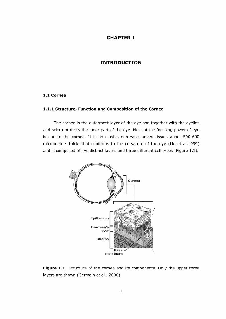
The cornea is the outermost layer of the eye and together with the eyelids
and sclera protects the inner part of the eye. Most of the focusing power of eye
is due to the cornea. It is an elastic, non-vascularized tissue, about 500-600
micrometers thick, that conforms to the curvature of the eye (Liu et al,1999)
and is composed of five distinct layers and three different cell types (Figure 1.1).
Figure 1.1 Structure of the cornea and its components. Only the upper three
layers are shown (Germain et al., 2000).
2
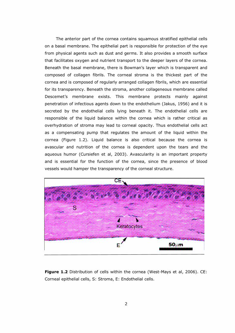
The anterior part of the cornea contains squamous stratified epithelial cells
on a basal membrane. The epithelial part is responsible for protection of the eye
from physical agents such as dust and germs. It also provides a smooth surface
that facilitates oxygen and nutrient transport to the deeper layers of the cornea.
Beneath the basal membrane, there is Bowman�s layer which is transparent and
composed of collagen fibrils. The corneal stroma is the thickest part of the
cornea and is composed of regularly arranged collagen fibrils, which are essential
for its transparency. Beneath the stroma, another collageneous membrane called
Descemet�s membrane exists. This membrane protects mainly against
penetration of infectious agents down to the endothelium (Jakus, 1956) and it is
secreted by the endothelial cells lying beneath it. The endothelial cells are
responsible of the liquid balance within the cornea which is rather critical as
overhydration of stroma may lead to corneal opacity. Thus endothelial cells act
as a compensating pump that regulates the amount of the liquid within the
cornea (Figure 1.2). Liquid balance is also critical because the cornea is
avascular and nutrition of the cornea is dependent upon the tears and the
aqueous humor (Cursiefen et al, 2003). Avascularity is an important property
and is essential for the function of the cornea, since the presence of blood
vessels would hamper the transparency of the corneal structure.
Figure 1.2 Distribution of cells within the cornea (West-Mays et al, 2006). CE:
Corneal epithelial cells, S: Stroma, E: Endothelial cells.
3
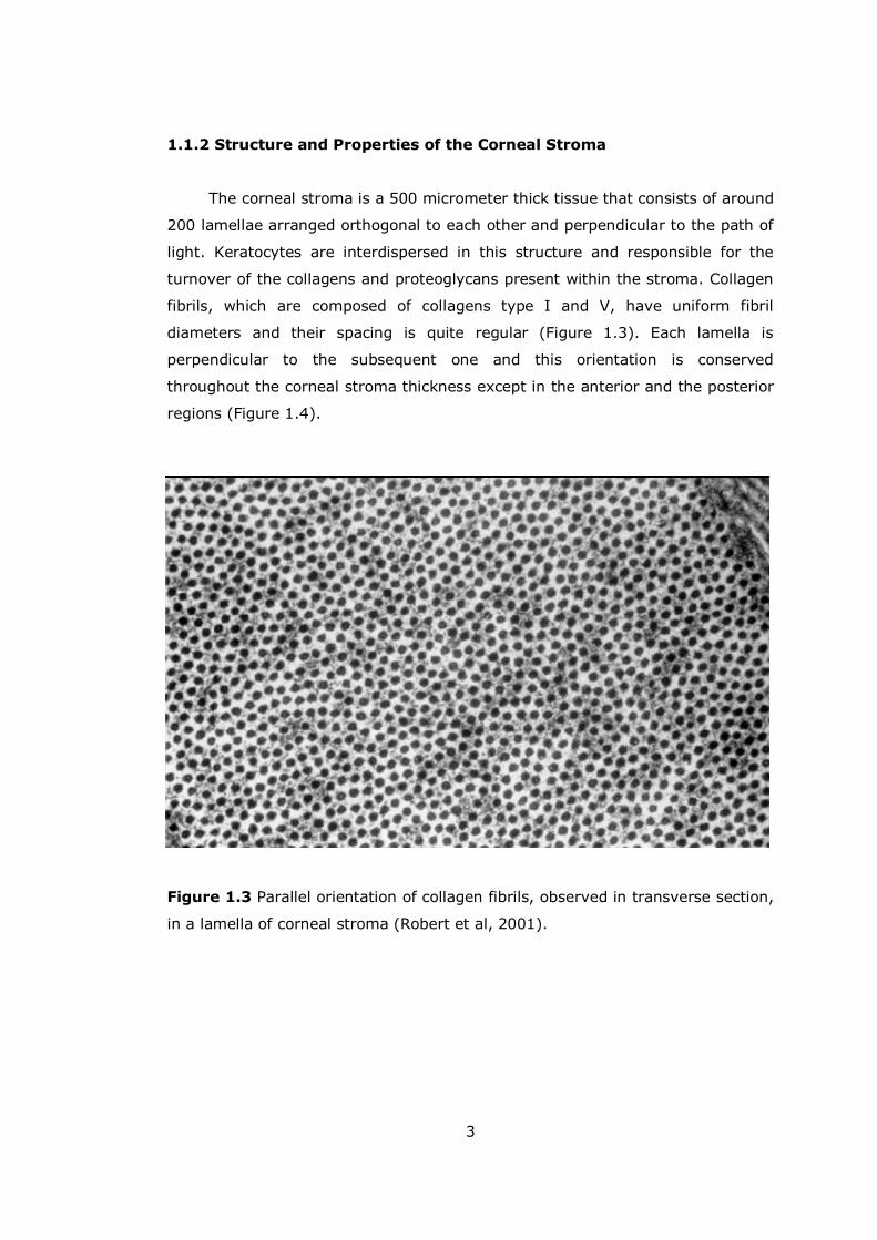
1.1.2 Structure and Properties of the Corneal Stroma
The corneal stroma is a 500 micrometer thick tissue that consists of around
200 lamellae arranged orthogonal to each other and perpendicular to the path of
light. Keratocytes are interdispersed in this structure and responsible for the
turnover of the collagens and proteoglycans present within the stroma. Collagen
fibrils, which are composed of collagens type I and V, have uniform fibril
diameters and their spacing is quite regular (Figure 1.3). Each lamella is
perpendicular to the subsequent one and this orientation is conserved
throughout the corneal stroma thickness except in the anterior and the posterior
regions (Figure 1.4).
Figure 1.3 Parallel orientation of collagen fibrils, observed in transverse section,
in a lamella of corneal stroma (Robert et al, 2001).

4
Figure 1.4 Perpendicular orientation of lamellae in corneal stroma (Meek et al,
2001).
The second important constituent of the corneal stroma extracellular matrix
(ECM) are the proteoglycans, which include keratocan, lumican and biglycan.
These proteoglycans are thought to be involved in the control of spacing of the
collagen fibrils. Their absence has been reported as a possible cause of loss of
transparency in several occasions, and knock-out mice (lumican deficient)
develop corneal haze (Chackravarti et al, 2000). They are generally found
perpendicularly aligned with respect to the collagen fiber in each lamellae and
are more randomly distributed within the thickness of the corneal stroma. Their
presence thus affects the overall structure of the corneal stroma. Also, as do the
other proteoglycans, they play a role in the maintenance of stromal hydration
(Funderburgh, 2000).
The highly oriented structure of the corneal stroma is an important factor
in both corneal transparency and mechanical stability (Meek et al, 1993; Dupps
et al, 2006). Corneal transparency is directly related to the regular spacing and
distinct diameter of the collagen fibers (Maurice, 1956). Normally, the refractive
index of the collagen fibrils is high, thus, a layer of collagen fibrils is expected to
scatter light; however this would only hold true if collagen fibrils were distributed
randomly within the stroma. However, due to the small diameter and short-
range order in the fibrillar organization, this scattering is reduced by the
5
phenomenon of �destructive interference�. This is further confirmed by the
diseases that disrupt this intricate organization and cause corneal opaqueness.
Furthermore keratocytes contain crystallins such as aldehyde dehydrogenase
and transketolase; which are shown to be highly expressed in cornea and these
crystallins also contribute to the transparency of the cornea (Jester et al, 1999).
This fine ultrastructural control is the essence of the functionality of the cornea.
The second important parameter is the hydration level of the collagen fibrils.
This is around 78% under normal conditions and in vitro examinations have
shown that increases in water content also causes a rise in light scattering. This
is generally explained by the disruption of the short range order of the corneal
collagen fibrils (Clark et al, 2004).
1.1.3 Corneal Keratocytes
Keratocytes are mesenchyme-derived cells that are responsible for the
organization and turnover of the corneal stromal ECM; hence they are essential
for the transparency of the cornea. There are around 2.5 x 10⁶ keratocytes
within the corneal stroma. Corneal keratocytes are themselves quite
transparent; which is generally related to the high expression of crystalline
proteins such as aldehyde dehydrogenase type III. Under normal conditions,
keratocytes are quiescent and have a stellate, flattened shape with long and
interconnecting extrusions. In injured cornea, these cells have the ability to
change their phenotype (Jester, 2003) into a more fibroblastic one in order to
increase the synthesis of the extracellular matrix components that are necessary
for the regeneration of the wound area. However, the extent of the injury and
the presence of the different signals direct keratocyte behavior such that
extensive corneal damage may induce keratocytes to secrete unorganized ECM
which may result in corneal haze (Funderburgh et al, 2003).
Upon injury, keratocytes close to the injury site go into apoptosis to
prevent further propagation of the injury (Wilson et al, 1998). Remaining cells
enter into the cell cycle, gradually losing their dendritic shape and beginning to
show more fibroblastic characteristics such as elongated, spindle�like shape,
aggressive proliferation and increased ECM secretion. The repair transition also
affects the transparency of the keratocytes, since fibroblastic conversion
decreases the expression of crystallins. This fibroblastic conversion may lead to
either fibroblastic or myofibroblastic phenotypes. Myofibroblasts become bigger
6
after conversion and they can be distinguished by the presence of smooth
muscle actin (SMA) fibers. These cells are responsible for wound contraction and
like the fibroblastic phenotype they secrete extensive extracellular matrix
components. None of these phenotypes, just like the keratocyte phenotype, is
terminal and following regeneration these cells can become keratocytes again.
These conversions are generally regulated by the epithelial cells; but cell-ECM
interactions have also been shown to be effective in triggering such conversions
(Fini et al, 1999).
1.1.4 Corneal Diseases and Dystrophies
Cornea associated problems can be due to physical damage such as
etching by strong acids, bases, over-exposure to UV light or genetic diseases and
fungal and bacterial infections. Although cornea is quite a resilient tissue with
significant regenerative capabilities in some cases, extensive damage cannot be
repaired by the usual approaches. Genetically inherited dystrophies can also
cause damage in the later stages of a patient�s life.
Corneal infections are quite infrequent but can happen due to
contaminated contact lenses, and penetration of fungi or bacteria into the cornea
can cause severe damage which may lead to loss of corneal transparency and
even result in corneal scarring (Chalupa et al, 1987; Huang et al, 2003). These
events, generally described as keratitis, can generally be solved by antibiotic or
antifungal treatment but there have been cases where permanent damage was
incurred too. There are also viral infections of the cornea; such as ocular herpes
and shingles which can cause significant damage (Wilson et al, 1997).
There are several genetically inherited corneal dystrophies. These
dystrophies generally affect the cornea gradually over time and might not lead to
permanent damage. Fuch�s dystrophy is one of the most common of several
corneal impairments and starts with the detachment of the endothelial lining
causing the swelling of the corneal stroma and subsequently its hydration. This
eventually leads to severe pain as hydration produces significant pressure within
the cornea, and also to blurred vision (Adamis et al, 1993). Although it is a fairly
slow-pace dystrophy, this may lead to total dysfunction of the cornea in elderly
people. Another dystrophy is keratocunus and can be defined as thinning of the
cornea (Kim et al, 1999). It generally starts within the stroma and gradually
7
affects the curvature of the cornea causing visual impairment. Mild cases can be
treated with lenses, however one fourth of the patients generally have extensive
distortions that need surgical intervention. Lattice dystrophy is due to synthesis
of unorganized fibrils within the stroma which in turn cause accumulation of
these proteins and leading to haziness. Another syndrome which is generally
related to long-term UV exposure is ptergyism which is the development of a
pinkish coloration within the cornea. When small, this growth generally does not
obscure visual acuity; however, when larger, deterioration can be severe.
The final major cause of vision loss due to corneal impairment is exposure
to chemical agents such as strong acids and bases, high penetration capability of
which can rapidly cause severe damage making it impossible for cornea to
recover.
1.1.4 Remedies for Cornea Related Health Problems
Some of the corneal dystrophies can be solved with Laser Photorefractive
Keratectomy (PRK) a method which has shown great promise but which is not
suitable in all cases. When the cornea is irreversibly damaged, the most widely
used solution is cornea transplantation. Since the cornea is an avascular tissue,
the possibility of rejection is quite low and this makes the cornea a superb tissue
for organ transplantation (Claesson et al, 2002). The main problem about cornea
transplantation is donor shortage which has become more significant with the
widespread use of corneal operations such as Laser Assisted in situ
Keratomileusis (LASIK) which renders donated corneas unusable. Other
problems are disease transmission from the donor tissue and possible function
loss during storage.
To overcome these problems several prostheses have been devised over
the last 20 years. These systems, generally referred to as keratoprostheses,
substitute for corneal functions of transparency and physical protection.
Application of keratoprostheses started in the 19th century with the unsuccessful
attempts made with glass implants. In the 20th century, several polymers such
as polymethylmethacrylate (PMMA), polyvinyl alcohol (PVA), poly(2-hydroxyethyl
methacrylate) (PHEMA) have been used to develop keratoprostheses (Chirilla et
al, 1998). The most prominent among these is the AlphaCor, previously known
as the Chirilla keratoprosthesis (Chirilla et al, 1998). The building block of
8
AlphaCor is PHEMA and it is composed of two distinct components; the central
optic and the skirt. The central optic is composed of a crosslinked PHEMA gel and
the skirt is a porous PHEMA sponge. While the central part acts as the main
corneal substitute, the skirt allows the integration of the keratoprosthesis with
the surrounding tissue due to the permissive nature of the porous structure to
cell migration (Hicks et al, 2000). AlphaCor has been developed over the last 15
years and successfully applied in the clinic to several blind patients (Hicks et al,
1998; Eguichi et al, 2004). Another group of keratoprostheses called osteo-
odonto keratoprostheses has been in use for the last 30 years (Ricci et al, 1992).
The advantages of keratoprostheses are their availability, ease of storage
and production. However, their integration with the body, their susceptibility to
infection and their effectiveness always remain in question. Keratoprostheses
can be evaluated in the context of first generation biomaterials; their main
problem is they are not removable and this can make them a liability when long
lifespan expectancy of the population is considered. This is one of the main
reasons behind the recent interest in applying tissue engineering to corneal
problems.
1.2 Tissue Engineering
1.2.1 Definition of Tissue Engineering
Tissue engineering is an emerging remedy for irreversible tissue damage
that causes great suffering all around the world. Its formal definition is: �Tissue
engineering is an interdisciplinary field that applies the principles of engineering
and of life science towards the development of biological substitutes that restore,
maintain, or improve tissue or organ function� (Langer et al, 1993).
Normal restorative systems of the human body may not cope with
extensive tissue damage and moreover some tissues such as nerve tissue have a
limited ability to regenerate. Methods such as implants or organ transplantation
(autografts, allografts, xenografts) have been tried in the past. However, all
these approaches have their own shortcomings. For example, prostheses have
inherent properties that do not match perfectly with the body and can cause
problems such as mechanical failure, additional tissue loss, infection or cancer in
the long run. For transplantations and grafts the risk of disease transmission,
9
tissue rejection and side-effects of long term immuno-suppression are always
severe possibilities. Moreover, scarcity of donor tissues is another issue. Thus
any method that would provide cheap, dependable, durable and transplantable
tissue substitutes would be of great service to patients as well as to physicians.
The main idea behind tissue engineering is to develop artificial tissue that
can be transplanted and may serve as a substitute or as a facilitator of normal
healing mechanisms without causing any adverse effects. There are two main
components of a tissue engineered product; cells and the carrier. The design of a
proper carrier for the target tissue, as well as obtaining, expanding and
manipulating the cells to be used are of utmost importance in tissue engineering
(Lavik et al, 2004).
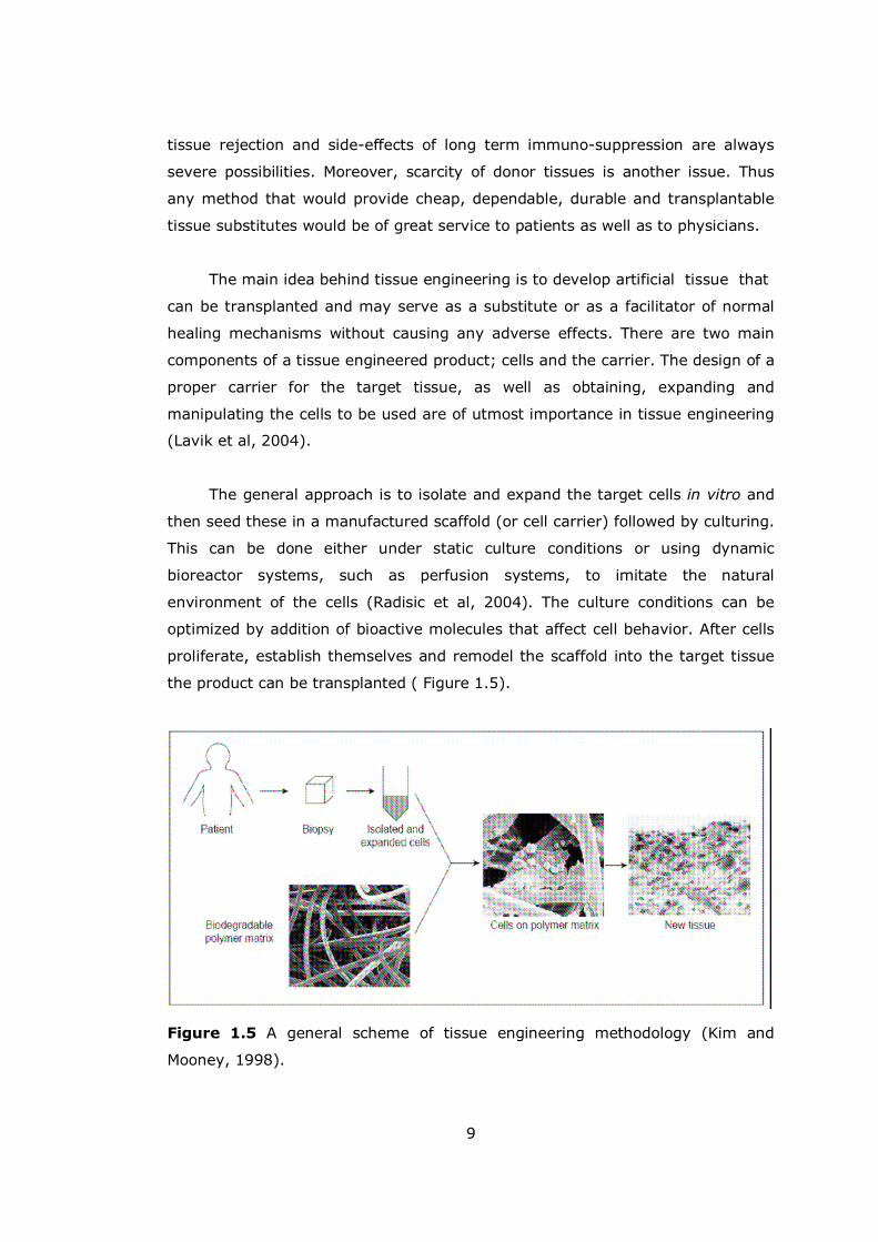
The general approach is to isolate and expand the target cells in vitro and
then seed these in a manufactured scaffold (or cell carrier) followed by culturing.
This can be done either under static culture conditions or using dynamic
bioreactor systems, such as perfusion systems, to imitate the natural
environment of the cells (Radisic et al, 2004). The culture conditions can be
optimized by addition of bioactive molecules that affect cell behavior. After cells
proliferate, establish themselves and remodel the scaffold into the target tissue
the product can be transplanted ( Figure 1.5).
Figure 1.5 A general scheme of tissue engineering methodology (Kim and
Mooney, 1998).

10
Tissue engineering has made significant progress over the last decade and
has reached some important goals, such as Food and Drug Administration (FDA)
approval of tissue engineered artificial skin and artificial cartilage (Apligraf®:
artificial skin, Organogenesis; Cartigel®: Artificial cartilage, Genzyme). Artificial
skin has been used in severe burn patients and diabetes related ulcerations for
quite some time with success. It is now possible to produce large areas of
artificial skin from isolated cells of epidermis and dermis.
1.2.2 Cell Sources for Tissue Engineering
Cell sources can be divided into three: autologous, allogenic and
xenogenic. Autologous cells are the patient�s own cells, allogenic cells are cells
that are expanded from a different person other than the patient, and xenogenic
cells are obtained from other species. The most preferred source is autologous
cells, because there is a lower risk of inflammation and the immune response is
practically nil. Allogenic and xenogenic sources can also be utilized, but with
caution. The utilization of embryonic or adult stem cells is an exciting new
possibility because these could be induced to differentiate into a range of cell
types after manipulation with chemical and biological cues. This is especially
helpful in cases where cell isolation is extremely hard.
The decision to use primary or stem cells mainly depends on the
proliferation ability of the cell type. Keratinocytes, osteoblasts and chondrocytes
can be isolated and expanded from a small biopsy at a reasonably fast rate. This,
however is not the case for all cell types. Moreover, expansion can cause
dedifferentiation in some cases. Use of embryonic stem cells can solve these
problems since they both have a huge self-renewal capacity and a potential for
directed differentiation (Bianco et al, 2001). There are certain social and ethical
issues concerning the use of embryonic stem cells in tissue engineering, which
can partially overcome by the use of adult stem cells. Recently there has been
another alternative, called universal cells, which have all their antigenic moieties
removed, and thus can be used for all patients (Shieh et al, 2005).
1.2.3 Tissue Engineering Scaffolds
A tissue engineering scaffold can be defined as a 2D or 3D designed
structure made of a, preferably biodegradable, material either of synthetic or
11
natural origin that would provide an hospitable microenvironment for the cells to
grow, differentiate and carry out their usual metabolic activity. These materials
are generally polymeric, but for hard tissue engineering some inorganic
materials such as titanium oxide or calcium phosphates are also being tested.
There are certain requirements that should be fulfilled by these materials such as
mechanical strength, controllable biodegradability, high porosity and optimum
pore size, in order to allow cell infiltration and transfer of nutrients and wastes,
as well as sufficient surface area and appropriate chemical and physical surface
properties to promote cell attachment, proliferation and migration (Karageorgiou
et al, 2005; Chua et al, 2003). In addition, these materials and their degradation
products should be biocompatible, i.e. non-toxic, non-immunogenic and non-
carcinogenic.
There are several types of materials that satisfy these requirements. Most
widely used synthetic and natural polymers for tissue engineering applications
are polyesters and the most prominent members of the synthetic group are
polyglycolic acid (PGA), polylacticacid (PLA) and their copolymers poly(lactic
acid-co-glycolic acid) (PLGA). These materials are FDA approved and their
popularity is partially related to this factor. They are being used in the design of
scaffolds for tissues like cartilage and bone (Hutmacher et al, 2000; Chen et al,
2006). These polyesters degrade through hydrolytic cleavage of the ester bonds
in their structure and their hydrophobicity affects their degradation rate. PGA
degrades quite fast (Half-life 20 days; Moran et al, 2003), thus it is not a optimal
choice for a large number of applications. On the other hand, PLLA degrades
extremely slowly (half-life 300 days, Lu et al, 2000), creating problems due to
the long term presence of the degrading polymeric material and its degradation
products. Copolymers with different lactic acid:glycolic acid ratios have provided
researchers with materials that would degrade in a desired manner depending on
the final destination of the tissue engineered product (Kim et al, 1998). Some
other polyesters such as polycaprolactone (PCL) (Pena et al, 2006) and
polyethyleneterephthalate (PET) (Lu, 2005). are also being used. Natural
polyesters for scaffold fabrication are; polyhydroxybutyrate (PHB) and
polyhydroxybutryate-co-hydroxyvalerate (PHBV) (Tezcaner, 2003; Kose, 2003).
In addition there are polyanhyrides (Gunatillake and Adhikare, 2003), poly(N-
isopropyl acrylamide; pNIPAM; Kubata et al, 2006) and polyurethanes
(Fromstein and Woodhouse, 2002) which have been shown to be appropriate for
tissue engineering applications.
12
Even though there are several synthetic compounds that almost completely
fulfill the requirements for a proper tissue engineering scaffold; the search for
better carriers goes on and utilization of natural polymers such as collagen and
elastin is desirable since these animal-originated materials naturally embody
most of the properties needed (Freyman et al, 2001).
Natural polymers can be human, animal or plant-originated or they may be
recombinant. These polymers are mainly polysaccharides and proteins.
Structural proteins found in the mammalian body are the most widely used ones.
Collagen and elastin have been used in a large number of tissue engineering
applications, most notably in skin, bone and cartilage tissue engineering (Lee et
al, 2001; Yamauchi et al, 2001; Daemen et al,2003; Ma et al, 2004). In addition
to these, other proteins from different sources such as silk have also been tested
(Li, 2006). Polysaccharides of the human body include glycosaminoglycan (GAG)
molecules such as chondroitin sulfate, dermatan sulfate and hyaluronic acid, and
other polysaccharides from other sources such as cellulose, chitosan and alginate
are also available (Pek, 2004; Müller, 2006). A third group that has been in use
is acellularized ECM models, such as acellularized muscle. These kind of
materials have less defined composition but have the advantage of being
originally modeled under in vivo conditions (Wei, 2005).
Natural polymers, however, pose problems such as inferior mechanical
strength, large variation in physical properties, rapid degradation and high cost.
Moreover, most of these polymers are hard to process due to their high
sensitivity to environmental conditions such as pH and temperature, and animal
and plant originated polymers are also induce an immune response.
1.2.4 Scaffold Fabrication Techniques
There are numerous methods to produce two and three dimensional tissue
engineering scaffolds depending on the shape, size and level of detail required.
For most of the macro-scale tissue engineering scaffolds, porosity is the most
crucial factor. There are several ways to produce a porous structure. Basic
techniques are porogen-leaching, gas foaming, freeze-drying, fiber bonding, and
phase separation (Ma, 2004). There are also �bottom up� techniques which use
advances in the field of CAD/CAM (Computer aided design and computer aided
manufacturing) to obtain porous structures.
13
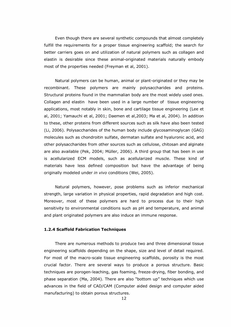
In the porogen leaching technique, a pore former such as sugar or salt is
introduced to a hydrophobic polymer solution and the solvent is removed by
evaporation. The resulting solid structure is then made porous by dissolving out
the porogen (Köse et al, 2003; Liu et al, 2006). Average pore size and porosity
of the structure can be adjusted by changing the amount and size of the porogen
used (Figure 1.6 a).
In gas-foaming, the structure is filled with a gas such as CO2 at high
pressure and then a sudden drop of pressure which leads to a decrease in the
solubility of the gas is used to develop gas bubbles followed by solidification to
leave pores behind (Harris et al, 1998; Park, 2002). The amount of the gas
dissolved in the solution, rate of pressure decrease and the diffusion properties
of the gas in the polymer involved affect the pore size and the porosity.
In freeze-drying, a polymer solution is frozen and then sublimation of the
solvent is achieved under very low pressure conditions to produce a porous
structure (Sumita, 2006; van Susante, 2001). With this technique structures
with more than 90% porosity can be achieved. Pore size and pore distribution
are dependent on polymer concentration, type of solvent used and rate of
freezing (Figure 1.6 b). With a uniform rate of freezing, highly homogenous
structures with a defined pore size can be achieved (Schoof et al, 2001). In fact,
freeze-drying is a subgroup of phase-separation techniques in which the main
concept is to separate a homogenous system into separate phase and the
removal of the one of the phases to attain a porous structure (Mikos and
Temenoff, 2000).
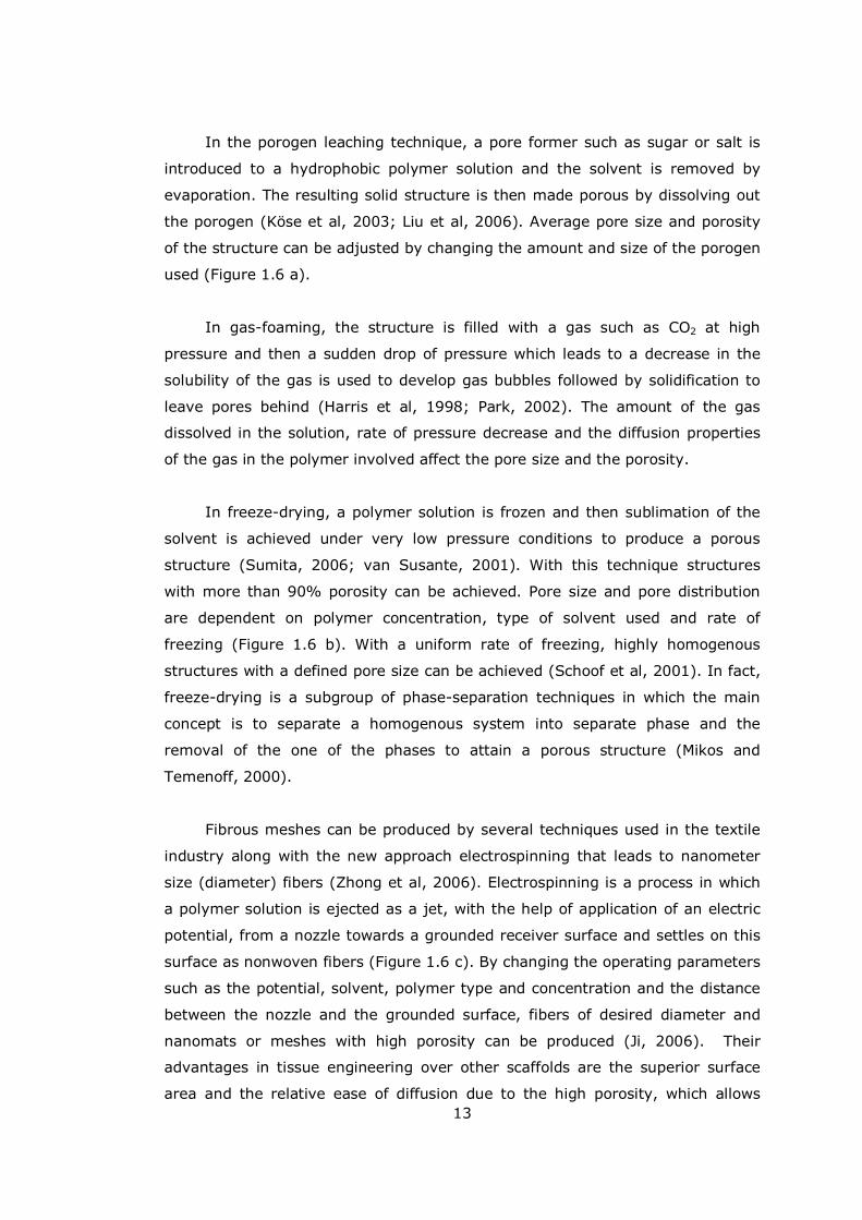
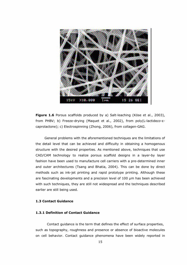
Fibrous meshes can be produced by several techniques used in the textile
industry along with the new approach electrospinning that leads to nanometer
size (diameter) fibers (Zhong et al, 2006). Electrospinning is a process in which
a polymer solution is ejected as a jet, with the help of application of an electric
potential, from a nozzle towards a grounded receiver surface and settles on this
surface as nonwoven fibers (Figure 1.6 c). By changing the operating parameters
such as the potential, solvent, polymer type and concentration and the distance
between the nozzle and the grounded surface, fibers of desired diameter and
nanomats or meshes with high porosity can be produced (Ji, 2006). Their
advantages in tissue engineering over other scaffolds are the superior surface
area and the relative ease of diffusion due to the high porosity, which allows
14
better transfer of nutrients. Fiber meshes, however, are generally mechanically
weak limiting their utilization. This problem can be overcome by physically
bonding the fibers to each other by thermal treatment or after coating the mesh
with an another polymer and removing this polymer after bonds are produced
(Mikos et al, 1993).
a
b
15
Figure 1.6 Porous scaffolds produced by a) Salt-leaching (Köse et al., 2003),
from PHBV; b) Freeze-drying (Maquet et al., 2002), from poly(L-lactideco-ε-
caprolactone); c) Electrospinning (Zhong, 2006), from collagen-GAG.
General problems with the aforementioned techniques are the limitations of
the detail level that can be achieved and difficulty in obtaining a homogenous
structure with the desired properties. As mentioned above, techniques that use
CAD/CAM technology to realize porous scaffold designs in a layer-by layer
fashion have been used to manufacture cell carriers with a pre-determined inner
and outer architectures (Tsang and Bhatia, 2004). This can be done by direct
methods such as ink-jet printing and rapid prototype printing. Although these
are fascinating developments and a precision level of 100 µm has been achieved
with such techniques, they are still not widespread and the techniques described
earlier are still being used.
1.3 Contact Guidance
1.3.1 Definition of Contact Guidance
Contact guidance is the term that defines the effect of surface properties,
such as topography, roughness and presence or absence of bioactive molecules
on cell behavior. Contact guidance phenomena have been widely reported in
c
16
both in vivo and in vitro conditions since being first defined by Harrison at the
beginning of 20th the century (Harrison, 1912). Cells respond to surface
topography and roughness and this response can direct cellular activities such as
locomotion, spreading, differentiation and extracellular matrix secretion. Cells
can recognize surface patterns down to nanometer scale and this property has
been tested with several cell types to achieve their alignment. Reaction of the
cells to a physical (3D) surface form depends on the dimensions and the shape
of the patterns (Curtis, 1987). If the pattern is that of successive grooves and
ridges and if the ridges and grooves are in the low micron range, cells generally
settle down and align themselves along the direction of the grooves. Upon
decreasing the pitch and the dimensions of the pattern, the same behavior can
be established on top of the ridges. More detailed observations have shown that
such cellular orientation has a direct effect on cell cytoskeleton, and labeling of
focal-adhesion forming proteins such as vinculin also shows alignment of the
focal adhesions (Walboomers, 2001). Moreover, such patterns have been found
to influence guidance of newly secreted extracellular matrix (Manwaring et al,
2003). The effect of patterning on cell growth is generally not significant and
generally correlates with that of unpatterned surfaces (Wan, 2004). But in
several cases, patterning has been shown to affect the rate of cell differentiation
(Kenar et al, 2006) and to enhance the development of the engineered tissue.
Examples are increased matrix deposition and calcification (Matsuzaka, 2003),
enhanced myotube formation with aligned myofibroblasts (Lam, 2006), neuron
migration (Bellamkonda, 2006) and differentiation of bone marrow stem cells
and neural progenitor cells (Recknor, 2006).
1.3.2 Methods for Micro and Nanopatterning
Microfabrication technologies were first developed in the microelectronics
industry to manufacture chips and other machine parts but some of these
methods have been modified for production of tissue engineering scaffolds.
The most prominent example of such techniques is photolithography, in
which the wafer (generally of silicon) to be patterned is coated with a photoresist
and exposed to high energy radiation through a mask and a pattern is obtained
on the photoresist. Afterwards the gaps in the photoresist allow the surface to be
etched either chemically or physically (Figure 1.7; Falconnet et al, 2006). The
resultant patterned wafer can then be used as a template from which an inverse

17
pattern is obtained after coating it with a polymer solution, drying and peeling. A
second possibility is the direct patterning of the bioactive molecules by
depositing them on the wafer produced and then removing the photoresist (Yap
and Zhang, 2006).
Figure 1.7 Schematic representation of the photolithography technique. The
first route is for producing surfaces with patterned bioactive molecules and the
second route is for production of patterned templates (Falconnet et al, 2006).
Another widely used method is microcontact printing in which a PDMS
replica of the wafer �stamp�, is immersed into a solution of a protein or another
biologically active molecule and the absorbed proteins are transferred by
stamping onto a surface; this way a topographically defined localization of these
proteins (such as RGD peptide sequence or cell-adhesion promoting proteins
such as laminin and fibronectin) can be achieved (Bhatia, 2000).
Another method to attach proteins on a surface is through using
microfluidics in which different solutions are allowed to flow through parallel
channels on a template in a controlled fashion leaving behind strips of the
proteins contained in the solutions adsorbed on the surface (Khaddemhosseini et
al, 2005) This can be achieved either by capillary driven flow, or when this is
insufficient, by pressure assisted movement of the bioactive molecule solution.

18
Microfluidic patterning techniques can also be used for cell micropatterning since
the conditions of the process are very mild (Folch et al, 2000).
Achieving nano-scale patterning, techniques such as hot-embossing
lithography and nanoimprinting can be used (Lee, 2006). More sophisticated
approaches such as electron-beam lithography or nanolithography with atomic
force microscope are also available (Hasirci et al, 2006).
All these techniques allow researchers to have a wide range of choices to
exploit contact guidance phenomenon on different levels.
1.4 Collagens
1.4.1 Properties of Collagens
Collagens are fibrous proteins. Fibrillar collagens have molecular weights of
around 300 kDa. They are a part of extracellular matrix and are secreted by
many cell types including connective tissue cells such as fibroblasts. They can be
found throughout the body and comprise the most abundant family of proteins in
mammals. Currently, 28 different types of collagen have been identified, which
differ in the structures of their component alpha chains. These differences cause
structural changes affecting self-assembly, fibril formation and network forming
capacity (Alberts et al, 2002; Myllyharju and Kivrikko,2001).
1.4.2 Collagen Structure
The collagen triple helix consists of polypeptide chains held together by
hydrogen bonding and, in some cases, interchain covalent crosslinks. This results
in a superhelical structure which is responsible for the stiffness and stability of
collagen molecules. In fibrillar collagens, each alpha chain contains about 1000
amino acids and molecules have lengths of 300 nm. Fibrillar collagens such as
the type I collagen, which is the most abundant member of the collagen family,
can form large fibrils up to 300 nm in diameter from individual collagen
molecules; fibrils can be further strengthened by crosslinking. These fibrils can
be as long as several hundred micrometers in normal adult tissues.
19
The collagen-like motif is rich in glycine, proline and hydroxyproline, all of
which are important for the stability of the helical structure of collagen. Every
third amino acid residue in the amino acid sequence is glycine whose regular
spacing is essential for the tight packing of the superhelical structure. Another
distinguishing property of collagen is the presence of hydroxyproline which is
specific to collagen.
1.4.3 Function of Collagen
The structure of collagen makes it resistant to tensile forces and in
general, collagens are found in the body where there is tensile stress. The
arrangement of the collagen fibrils depends on the direction of the tensile stress
on the tissues. In skin, collagen fibrils can be found as dispersed bundles since
skin elasticity requires resistance to tensile stresses in any direction. On the
other hand, for ligaments and tendon whose movement and thus the application
of the stress is restricted to one direction, collagen fibrils can be found as
regularly arranged bundles in a certain direction, parallel to the stress axis. In
bone a similar organization can be observed in which oriented fibrils of collagen
also act as carriers for the cells and deposited minerals.
Collagens also provide surfaces for cells to attach and migrate on. This
process is quite important in the remodeling of the collagen structure within the
tissue because forces exerted on the collagen fibrils reorient and align them in
response to the actions of the cells. This is a two-way road in which cellular
activities affect the alignment of the collagen fibrils and this causes the
alignment of the cells in return. This feature is quite important and is being
exploited in tissue engineering applications.
1.4.4. Use of Collagen in Tissue Engineering
Collagens have been utilized by several groups quite efficiently in tissue
engineering applications. Perhaps the most notable of these is the use of
collagen foams in artificial skin (Freyman et al, 2001). Collagen has been used
as an efficient wound dressing material since the first half of the 20th Century;
but success in cultivation of human fibroblasts within collagen sponges has
shifted the attention toward tissue engineered skin (Jones, 2002). Even though
there are established, FDA-approved collagen-based artificial skin products,
20
studies concerning the optimization of such structures either by changing the
production conditions or by addition of complementary materials such as GAGs,
the mechanisms behind the remodeling processes (cell population, cell
penetration into the matrices, gene expression pattern within the scaffolds etc.)
and their in vivo performance either in animal models or in clinical trials are still
going on (Kuroyanagi et al, 2001;Gingras et al, 2003; Boyce, 2004; Helary et
al, 2005;Ng and Hutmacher, 2006).
As one of the most widely used materials in tissue engineering, collagen
based matrices have been tried in various applications such as bone engineering,
cartilage engineering, muscle tissue engineering, vascular grafts etc. (van
Susante, 2001; Yaylaoglu et al, 1999). For cartilage tissue, in vitro model
studies with collagen foams have shown good cell proliferation and also
preservation of chondrocytic phenotype (Pieper et al, 2002; Stark et al, 2006).
Collagen foams have also been utilized to repair cartilage defects in in vitro
model studies and results showed that collagen matrices populated with
chondrocytes had a better repair response in comparison to both untreated
defects and defects treated with collagen matrix only (Dorotka et al, 2005; Köse
et al 2005). Good results were also obtained with chondrocyte seeded collagen
gels (Galois et al, 2005).
In bone tissue engineering, collagen scaffolds or collagen containing hybrid
scaffolds appear to be very promising. Cell proliferation and differentiation have
been observed in collagen gels and collagen films (Wiesmann et al, 2003;
Ignatius et al, 2005; Ber et al, 2005). For bone tissue engineering collagen has
frequently been incorporated into composite scaffolds. With
Collagen/Hydroxyapatite (HAp) 3D scaffolds, three dimensional cellular
orientation and new matrix deposition by osteogenic cells was observed (Du et
al, 1998. Another collagen-HAp scaffold was also shown to be suitable for
osteoinduction and osteoconduction (Rodrigues et al, 2003).
Collagen has been used in a variety of forms such as foams, gels, films,
fibers or as composites and also in combination with several other materials such
as elastin, chondroitin sulfate and polymethylmethacrylate (PMMA) (Pieper,
1999; Harada, 2000). Not only collagen but also gelatin (denatured collagen)
has been successfully used in cartilage tissue engineering applications. Collagen
matrices loaded with bioactive agents such as growth factors have been utilized

21
for applications like cartilage tissue engineering (Lee, 2004). In general, collagen
based scaffolds are good for cell adhesion and proliferation, but have low
mechanical strength and are rapidly degraded unless stabilized via crosslinking
(Angele, 2004; Lee, 2001). Also, there are large discrepancies between the
properties of collagens from different sources. Thus, research on the behavior of
different cell carriers produced with collagens from different sources, novel
scaffold structures, and development of new crosslinking techniques continues
(Itoh et al, 2001; Tsai et al 2002, Yunoki et al, 2004; Chen et al, 2005).
1.4.5. Tissue Engineering Approaches for Cornea
There have been several attempts to produce corneal equivalents via
tissue engineering. For the epithelial layer, studies have focused on the
production of surfaces that are conducive for proliferation of epithelial cells and
cues that would lead to total coverage of the surface. To this end, fibrin,
epidermal growth factor (EGF) coated polydimethylsiloxane (PDMS) films and
crosslinked collagen gels have been used (Rama et al, 2001; Klenkler et al,
2005; Duan and Sheardown; 2006). PDMS films and collagen gels have
performed well under in vitro conditions and the fibrin substrate has gone
through clinical trials with considerable success.
As corneal stroma substitutes, thick dermal collagen type I foams have
been produced and these matrices when seeded with human keratocytes showed
good cell proliferation and mechanical properties (Orwin, 2000; Orwin, 2003).
Collagen hydrogels have also been tried and but even though they had superior
transparency, they were mechanically weak (Li, 2004). In another attempt
(Germain et al., 1999), corneal keratocytes were seeded within a collagen type I
and type III gel; this resulted in quite a transparent structure but contractile
activities of the keratocytes contracted the gel. Interwoven PGA meshes seeded
with keratocytes were studied under in vivo conditions and clarification of the
implant was observed in a four month period (Hu, 2005). Although all these
trials have had promising results; there is not a definitive artificial cornea design.
In this study; three different collagen based scaffolds (two foams of a
constant thickness produced from two different collagen sources and one
micropatterned collagen film) were assessed for their suitability as cell carriers
for keratocytes to construct an artificial corneal stroma. Two different collagen
22
foams with a pre-defined thickness (between 500 and 700 µm) were produced.
Due to the fact that the natural corneal stroma structure is highly oriented; the
substitute corneas should carry physical (3D) patterning to mimic the natural
tissue. The effect of micropatterning on cell behavior (cell alignment, ECM
secretion) and effects of cell response to physical cues (carrier transparency,
mechanical strength) have been tested to determine whether incorporation of
micropatterns in an artificial cornea design would be beneficial especially when
tested as a stroma. Results have shown that collagen foams made of collagen
type I isolated from bovine trachea (insoluble) or rat tail (soluble) were suitable
for keratocyte growth; but development of transparency was slow. On the other
hand, micropatterning was effective both in achieving transparency and
improvement of the mechanical properties of the films. Thus it was concluded
that micropatterning should be integrated to the design of a 3-D corneal scaffold
to facilitate the remodeling process.
23
CHAPTER 2
MATERIALS AND METHODS
2.1 Materials
Rat tail type I collagen (purity 99%) was bought from BD Sciences (USA).
Insoluble collagen type I (from bovine trachea), EDC (N-Ethyl-N�-[3-
dimethylaminopropyl]carbodiimide), N-hydroxysuccinimide (NHS), collagenase
type IA (activity: 449 units/mg solid), newborn calf serum, trypsin/EDTA,
Amphothericin B, monoclonal anti-human collagen type I antibody,
glutaraldehyde, cacodylic acid (sodium salt) and DAPI were purchased from
Sigma-Aldrich Corporation (Germany). Fetal calf serum, Dulbecco�s Modified
Eagle Medium (DMEM; low glucose) were obtained from PAA (Austria).
Alexifluor488 conjugated anti-mouse Ig antibody was from Molecular Probes
(USA), Anti-human CD34 antibody was bought from Santa Cruz (USA) and b-
FGF from Invitrogen (USA). Dulbecco�s Modified Eagle Medium (DMEM; high
glucose) and Ham�s F12 medium were supplied by Gibco (USA). Anti-human
keratan sulfate antibody was from Chemicon Inc (USA). Formaldehyde, acetic
acid, sodium dihydrogen phosphate and disodium hydrogen phosphate were
obtained from Merck (Germany). NucleoCounter reagents were supplied by
Chemometec (Denmark) and MTS cell proliferation assay solution was from
Promega (USA). Acridine Orange was obtained from BDH Chemicals Ltd. (UK)
and Sylgard 184 elastomer solution was from Dow Corning (USA).

24
2.1.1 Cells
Human corneal keratocytes (primary culture) were provided by Dr. Odile
Damour (Cornea Bank of Edouard Herriot Hospital, Lyon, France). D407 Retinal
pigment epithelial cells were a kind gift of Dr. R. Hunt (Department of
Ophthalmology, University of South Carolina Medical School). For all
experiments, keratocytes between passages 4-8 and D407 cells between
passages 10-14 were used. Cells were stored in a liquid nitrogen tank.
2.2 Methods
2.2.1 Template Preparation
Silicon templates were manufactured by Prof. Dr. Atilla Aydõnlõ (Bilkent
University Physics Department, Ankara) by photolithography and chemical-
etching with the dimensions given below (Table 2.1). Elastomer templates with
patterns inverse to the silicon wafers were also produced by the same lab using
Sylgard 184 elastomer solution. Solutions were poured on to the silicon
templates and after thermal curing (45 min at 100 °C) solidified elastomer was
peeled off. Final templates had the inverse pattern dimensions of the template
pattern dimensions (Figure 2.1).
Table 2.1 Template dimensions
Groove Depth
(µm)
Groove Width
(µm)
Ridge Width
(µm)
Inclination Angle
(degrees)
30 2 10 54.7
25
Figure 2.1 Macroscopic appearance of the elastomer template.
2.2.2 Collagen Film Production
2.2.2.1 Micropatterned Collagen Film Production
Micropatterned collagen films were prepared by the solvent casting
method. Collagen solutions (15 mg/mL in 0.5 M acetic acid) were prepared by
mild agitation at 29 ºC and after total dissolution 200 µL was poured onto the
patterned template and air-dried overnight under a hood. Dry films were
removed from the template surface using forceps and stored in a desiccator at
room temperature until use.
2.2.2.2 Unpatterned Collagen Film Production
For unpatterned collagen films, 200 µL collagen solution was poured onto
smooth and flat PDMS surfaces and processed as described above.
26
2.2.3 Collagen Foam Production
2.2.3.1 Foam Production from Insoluble Collagen
Insoluble collagen (12 mg/mL) was suspended in acetic acid (0.5 M) and
then this suspension was homogenized at 900 rpm at 4 °C using a Sartorius
Potter S homogenizer for 30 seconds three times with a 30 second pause in
between. Final 1 mL aliquots were poured into plastic tissue culture plates and
frozen at -20 °C overnight and then lyophilized at -80 °C at 133 x10-6 bar
vacuum for 8 h (Labconco Freezone Freeze-drier system, USA). Foams were
stored in a desiccator at room temperature until use.
2.2.3.2 Production of Foams from Rat Tail Collagen
2.2.3.2.1 Uncrosslinked Foam Production
Rat tail collagen solution (750 µL at 3 mg/mL in 0.02% acetic acid) was
poured into plastic tissue culture plates, frozen at -20 °C overnight and then
lyophilized at -80 °C at 133 x10-6 bar vacuum for 8 h.
2.2.3.2.2 Pre-Crosslinked Foam Production
Rat tail collagen solution (750 µL of 3 mg/mL in 0.02% acetic acid) was
poured into plastic tissue culture plates and EDC/NHS solution (100 µL in 50 mM
NaH2PO4 (pH 5.5) buffer) was added to each plate to reach a final w/w ratio of
1.13/1/1 of EDC/Collagen/NHS. After vigorous mixing, the final solution was
incubated for 2 h at room temperature and then lyophilized at -80 °C at 133
x10-6 bar vacuum for 8 h.
2.2.4 Scaffold stabilization
Patterned and unpatterned collagen films and insoluble collagen foams
were crosslinked by the non-toxic crosslinking method, using EDC/NHS.
Scafffolds were immersed into a solution of EDC/NHS (33 mM and 6 mM
respectively) in a 50 mM NaH2PO4 buffer (pH 5.5) for 2 h at room temperature.
Then the pH of the system was neutralized by incubating the scaffolds in 0.1 M
27
Na2HPO4 (pH 9.1) buffer for 1 h followed by washing steps in 2M and 1M NaCl
solutions. Lastly scaffolds were rinsed with distilled water several times and air
dried.
2.2.5 Scaffold Characterization
2.2.5.1 Film and Foam Thickness Measurement
Film and foam thicknesses were measured using a standard micrometer
(Erste Qualitat, Germany) to a sensitivity of 0.1 µm before and after
crosslinking. Each sample was measured at least three times and for both
crosslinked and uncrosslinked specimens 6 samples were used.
2.2.5.2 Measurement of Surface Porosity of Foams
Porosity of the foams and the presence of a skin layer was assessed from 4
micrographs taken by a Nikon SMZ 1900 Stereomicroscope (Japan) of both the
upper and lower surfaces of the foams and porosity was determined by analyzing
these images with the NIH Scion image program.
2.2.5.3 Bulk Porosity of foams
In order to determine the porosity of the foams, the volume occupied by
the collagen in uncrosslinked insoluble collagen foams and crosslinked insoluble
and rat tail foams (6 of each) was determined using a helium pycnometer
(Ultrapycnometer 1000, Quantachrome Corporation, USA). Then porosity was
calculated as the ratio of the volume of the collagen determined to the volume of
the foam calculated from its dimensions.
2.2.5.4 Pore Size Distribution
Pore size distribution of the both crosslinked and uncrosslinked foams
were determined using a mercury porosimeter (Quantachrome Corporation,
Poremaster 60, USA) under low pressure conditions.
28
2.2.5.5 Degradation in situ
In order to study the degradation profile, scaffolds were incubated under
normal culture conditions (in sterile 24 well plates at 37 °C and under 5% CO2)
in sterile 10 mM PBS (pH 7.4). The extent of degradation was examined at time
points 1, 2 and 4 weeks with SEM, stereomicroscopy, gravimetry and by medium
pH measurements.
2.2.5.5 Stability of Scaffolds: Collagenase Assay
To study the resistance of patterned collagen films to enzymatic
degradation, pre-weighed films were incubated in collagenase A solution (0.1
mg/mL in sterile PBS pH 7.4) for periods of 1, 2 and 3 h. Films were then rinsed
several times with distilled water and weighed after lyophilization to determine
weight loss.
2.2.6 SEM examination
All samples were examined by SEM. Unprocessed scaffolds were stuck
after excessive rinsing with cacodylate buffer (pH 7.4), lyophilized, gold-coated
under vacuum with a sputter coating device (Hummle VII, Anatech, USA ) and
observed with scanning electron microscope (JSM 6400, JEOL, Japan).
2.2.7 In vitro Studies
2.2.7.1 Cell Culture
All cells were stored frozen in a liquid nitrogen tank in their respective
medium with addition of 15% DMSO until use. Following thawing, cells were
used after reaching confluency and passaged one more time. All cell culture
experiments were conducted under standard culture conditions. Cells were
incubated in a CO2 incubator at 37 °C and 5% CO2.
29
2.2.7.1.1 Keratocyte Culture
Human keratocytes were received in a tissue culture flask in dry ice
(passage 2 and passage 4) and propagated until passage 8. In all experiments
keratocytes between passage 4-8 were used. The composition of the keratocyte
medium for 500 ml was as follows: 225 mL of DMEM high glucose, 225 ml of
Ham F12 medium, 50 mL of new born calf serum, 10 ng/mL human recombinant
b-FGF, amphotericin (1 µg/ml), streptomycin (100 µg/ml) and penicillin (100
UI/mL).
2.2.7.1.2 D407 Culture
D407 cells between passages 10-14 were used in the experiments. The
composition of 500 mL medium was as follows: 475 mL of DMEM high glucose,
25 mL of fetal calf serum, amphotericin (1 µg/ml), streptomycin (100 µg/ml) and
penicillin (100 UI/mL).
2.2.7.2 Cell Seeding onto Scaffolds
Cells were detached from the flask surface by treatment with 0.25%
trypsin for 5 min at 37 °C. After detachment, trypsin was deactivated with serum
and cells were collected by centrifugation. Cells were then counted with a
Nucleocounter (Appendix A). After determination of the cell number, 50 µL of
keratocyte containing medium was seeded onto each film and foam. For the
determination of growth profile, transparency, keratan sulfate content and for
DAPI and CD34 staining, 1x10⁴ keratocytes per film were used. For mechanical
tests, f-actin and collagen type 1 staining, 5x10⁴ cells were used. For foams
5x10⁴ cells were used. After seeding, the scaffolds were incubated for cell
attachment in a CO2 incubator for 1 h, then at the end of 1 h the volume of the
medium was completed to 500 µL under sterile conditions.
2.2.7.3 Cell Proliferation on Scaffolds
To examine cell proliferation on and within the scaffolds, the MTS cell
proliferation assay was carried out for each scaffold in triplicate for days 1, 4, 7
and 10. For each time point, the medium was discarded and the well was
washed with sterile PBS to remove any remaining medium. Then 10% MTS
30
solution (500 µL) was added and scaffolds were incubated at 37 °C and 5% CO2
for 2 h. After 2 h, 100 µL of the solution was transferred to a 96-well plate and
absorbance was determined at 490 nm using an Elisa plate reader (Molecular
Devices, USA). To correlate the absorbance with the cell number, a calibration
curve of known cell numbers was constructed (see Appendix A).
2.2.8 Microscopical Studies
2.2.8.1 Acridine Orange Staining
Keratocyte seeded collagen films were fixed after days 1, 7, 14 and 21 with
2.5% glutaraldehyde solution for 2 h. Afterwards, films were rinsed with PBS and
10% Acridine Orange was applied for 15 min while protecting specimens from
light exposure. The specimens were rinsed with PBS and observed using an
Olympus IX-70 (Japan) fluorescence microscope with WB filter (450-480 nm).
For rat tail collagen foams the same procedure was carried out after 14 days of
incubation.
2.2.8.2 DAPI Staining
Keratocyte seeded patterned and unpatterned films and D407 seeded
patterned films were stained with the nuclear stain DAPI. After fixation in 4%
formaldehyde solution for 15 min, specimens were rinsed with PBS and then
DAPI solution (diluted 1:1000 in PBS solution) was applied onto the scaffolds
which were incubated at 37 °C in the dark for 45 min. Afterwards, specimens
were rinsed with PBS and examined using an Olympus IX-70 fluorescence
microscope with WU filter (330-385 nm).
2.2.8.3 SEM Examination
Patterned collagen films seeded with keratocytes after days 7, 10, 14 were
fixed with 2.5% glutaraldehyde in cacodylate buffer (pH 7.4) for 2 h and then
washed with cacodylate buffer and with distilled water several times and freeze-
dried. Afterwards samples were gold coated by sputtering and observed with a
scanning electron microscope. The same approach was applied to D407 cells on
films and to insoluble collagen foams seeded with keratocytes after day 7.
31
2.2.8.4 FITC-Labelled Phalloidin Staining
To observe the orientation of cytoskeletal actin filaments, in cells on
patterned collagen films, FITC labeled phalloidin staining was performed. This
was applied to keratocyte seeded patterned collagen films after 7 days of
incubation. Samples were fixed with 4% formaldehyde for 15 min and then
washed with PBS (pH 7.4). Cell membranes were permeabilized with a 1%
Triton-X100 solution for 5 min. After washing, samples were incubated at 37 °C
for 1 h in 1% PBS-BSA solution. After washing, FITC labeled phalloidin (1:100
dilution in 0.1% PBS-BSA) was added and samples were incubated for another 1
h. Samples were transferred to a microscope slide and covered with 50% PBS-
glycerol and observed using an Olympus IX-70 (Japan) fluorescence microscope
with WB filter (450-480 nm).
2.2.8.5 Immunostaining
2.2.8.5.1 Collagen Type I Staining
In order to study extracellular matrix (ECM) secretion by keratocytes and
D407 cells, indirect immunostaining with anti-collagen type I antibody was
performed. Films seeded with keratocytes and D407 cells were fixed with 2.5%
formaldehyde for 15 min on days 1 and 7. After washing with PBS (pH 7.4), cell
membranes were permeabilized with 1% Triton-X100 solution for 5 min. After
washing, samples were incubated at 37 °C for 1 h in 1% PBS-BSA solution. Anti-
human collagen type I antibody produced in mice (1:200 dilution in 0.1% PBS-
BSA solution) was then added onto the specimens followed by incubation for 1 h
at 37 °C. Samples were washed with 0.1% PBS-BSA solution and Alexifluor488-
labelled Anti-mouse antibody produced in goat (1:100 dilution in 0.1% BSA-PBS)
was added and incubated at 37 °C for another hour and then washed with 0.1%
PBS-BSA solution. Samples were observed using an Olympus IX-70 (Japan)
fluorescence microscope with WB filter (450-480 nm).
2.2.8.5.2 Keratan Sulfate Staining
In order to determine the presence of the keratocyte-specific
proteoglycan, keratan sulfate, films seeded with keratocytes were stained for
keratan sulfate on days 1 and 7 with indirect immunostaining. Samples were
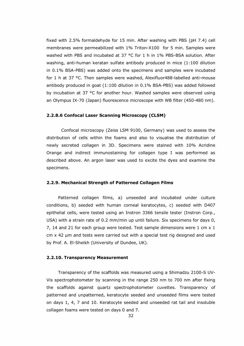
32
fixed with 2.5% formaldehyde for 15 min. After washing with PBS (pH 7.4) cell
membranes were permeabilized with 1% Triton-X100 for 5 min. Samples were
washed with PBS and incubated at 37 °C for 1 h in 1% PBS-BSA solution. After
washing, anti-human keratan sulfate antibody produced in mice (1:100 dilution
in 0.1% BSA-PBS) was added onto the specimens and samples were incubated
for 1 h at 37 °C. Then samples were washed, Alexifluor488-labelled anti-mouse
antibody produced in goat (1:100 dilution in 0.1% BSA-PBS) was added followed
by incubation at 37 °C for another hour. Washed samples were observed using
an Olympus IX-70 (Japan) fluorescence microscope with WB filter (450-480 nm).
2.2.8.6 Confocal Laser Scanning Microscopy (CLSM)
Confocal microscopy (Zeiss LSM 9100, Germany) was used to assess the
distribution of cells within the foams and also to visualise the distribution of
newly secreted collagen in 3D. Specimens were stained with 10% Acridine
Orange and indirect immunostaining for collagen type I was performed as
described above. An argon laser was used to excite the dyes and examine the
specimens.
2.2.9. Mechanical Strength of Patterned Collagen Films
Patterned collagen films, a) unseeded and incubated under culture
conditions, b) seeded with human corneal keratocytes, c) seeded with D407
epithelial cells, were tested using an Instron 3366 tensile tester (Instron Corp.,
USA) with a strain rate of 0.2 mm/min up until failure. Six specimens for days 0,
7, 14 and 21 for each group were tested. Test sample dimensions were 1 cm x 1
cm x 42 µm and tests were carried out with a special test rig designed and used
by Prof. A. El-Sheikh (University of Dundee, UK).
2.2.10. Transparency Measurement
Transparency of the scaffolds was measured using a Shimadzu 2100-S UV-
Vis spectrophotometer by scanning in the range 250 nm to 700 nm after fixing
the scaffolds against quartz spectrophotometer cuvettes. Transparency of
patterned and unpatterned, keratocyte seeded and unseeded films were tested
on days 1, 4, 7 and 10. Keratocyte seeded and unseeded rat tail and insoluble
collagen foams were tested on days 0 and 7.

33
2.3 Statistical Analysis
Statistical analysis was carried out by the Student�s t-test; p≤0.05 was
considered significant.
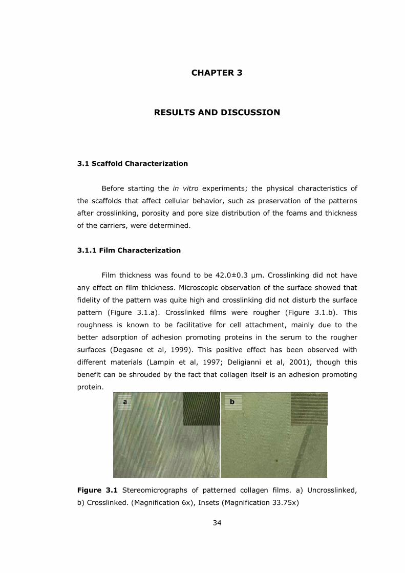
34
ba
CHAPTER 3
RESULTS AND DISCUSSION
3.1 Scaffold Characterization
Before starting the in vitro experiments; the physical characteristics of
the scaffolds that affect cellular behavior, such as preservation of the patterns
after crosslinking, porosity and pore size distribution of the foams and thickness
of the carriers, were determined.
3.1.1 Film Characterization
Film thickness was found to be 42.0±0.3 µm. Crosslinking did not have
any effect on film thickness. Microscopic observation of the surface showed that
fidelity of the pattern was quite high and crosslinking did not disturb the surface
pattern (Figure 3.1.a). Crosslinked films were rougher (Figure 3.1.b). This
roughness is known to be facilitative for cell attachment, mainly due to the
better adsorption of adhesion promoting proteins in the serum to the rougher
surfaces (Degasne et al, 1999). This positive effect has been observed with
different materials (Lampin et al, 1997; Deligianni et al, 2001), though this
benefit can be shrouded by the fact that collagen itself is an adhesion promoting
protein.
Figure 3.1 Stereomicrographs of patterned collagen films. a) Uncrosslinked,
b) Crosslinked. (Magnification 6x), Insets (Magnification 33.75x)
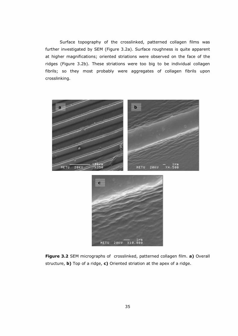
35
Surface topography of the crosslinked, patterned collagen films was
further investigated by SEM (Figure 3.2a). Surface roughness is quite apparent
at higher magnifications; oriented striations were observed on the face of the
ridges (Figure 3.2b). These striations were too big to be individual collagen
fibrils; so they most probably were aggregates of collagen fibrils upon
crosslinking.
Figure 3.2 SEM micrographs of crosslinked, patterned collagen film. a) Overall
structure, b) Top of a ridge, c) Oriented striation at the apex of a ridge.
a b
c
36
3.1.2 Foam Characterization
3.1.2.1 Crosslinking
Crosslinking of rat tail (RT) collagen foams with conventional methods
(immersion of the scaffold into the crosslinking medium) leads to extreme
shrinkage (Table 3.1) and loss of porous structure (Figure 3.3). However,
conventional crosslinking did not result in a dramatic change in the thickness of
the insoluble collagen foams. Initial and final thicknesses are given in Table 3.1.
Other researchers have also observed varying degrees of shrinkage when
collagens from different sources were used (Angele et al, 2004).
In order to prevent shrinkage and to have a better control on the final
thickness of the foam, the RT collagen solution was crosslinked with EDC/NHS
before the resultant foams were made and foams preserved 74.6% of their
original thickness (Table 3.1, Figure 3.4). Thickness has not been taken into
consideration in the reported designs in the literature, but it is important for the
ease of remodeling in vivo and it is also crucial during implantation.
Figure 3.3 Effect of conventional crosslinking on rat tail collagen foams. a)
Uncrosslinked, b) Crosslinked foam (Magnification x 6).
a b

37
Figure 3.4 Structure of pre-crosslinked collagen foam. a) Macroscopic view
(Magnification x 6) b) Surface characteristics (Magnification x 33.75).
Table 3.1 Foam thickness before and after crosslinking (µm).
Foam type/Treatment Rat Tail Insoluble
Uncrosslinked 721±17.6 1150.3±39.6
Crosslinked 72.3±4.1 811.3±25.2
Pre-crosslinked 531.6±23.7 -
3.1.2.2 Surface Porosity
Surface porosity of the collagen foams made from rat tail and the
insoluble collagen are presented in Table 3.2. It is a fact that the lyophilization
procedure causes the formation of a layer of lower porosity, �skin layer�, both at
the top and the bottom of the foams. This may adversely affect the cell and
nutrient penetration especially when seeding is done using the upper surface. To
quantify this effect, upper and lower surface layers of the collagen foams were
compared in terms of their porosity using stereomicrographs and an image
processing program. The skin layer was present in insoluble collagen foams (but
the porosity of the upper surface was high enough for in vitro studies, see
Section 3.3). The top skin layer of rat tail collagen foams was more porous than
that of the insoluble foams. Slightly higher porosity of the upper part of the rat
ba
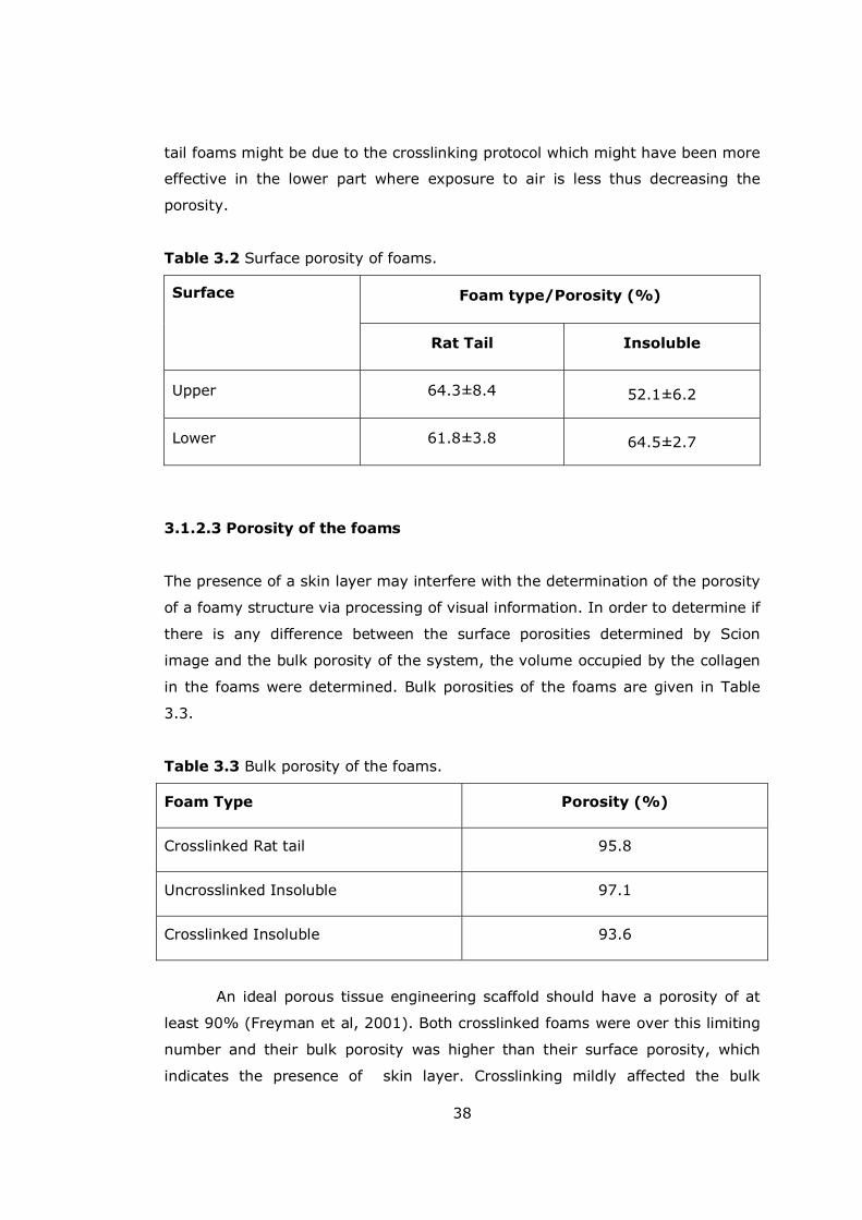
38
tail foams might be due to the crosslinking protocol which might have been more
effective in the lower part where exposure to air is less thus decreasing the
porosity.
Table 3.2 Surface porosity of foams.
Foam type/Porosity (%) Surface
Rat Tail Insoluble
Upper 64.3±8.4 52.1±6.2
Lower 61.8±3.8 64.5±2.7
3.1.2.3 Porosity of the foams
The presence of a skin layer may interfere with the determination of the porosity
of a foamy structure via processing of visual information. In order to determine if
there is any difference between the surface porosities determined by Scion
image and the bulk porosity of the system, the volume occupied by the collagen
in the foams were determined. Bulk porosities of the foams are given in Table
3.3.
Table 3.3 Bulk porosity of the foams.
Foam Type Porosity (%)
Crosslinked Rat tail 95.8
Uncrosslinked Insoluble 97.1
Crosslinked Insoluble 93.6
An ideal porous tissue engineering scaffold should have a porosity of at
least 90% (Freyman et al, 2001). Both crosslinked foams were over this limiting
number and their bulk porosity was higher than their surface porosity, which
indicates the presence of skin layer. Crosslinking mildly affected the bulk
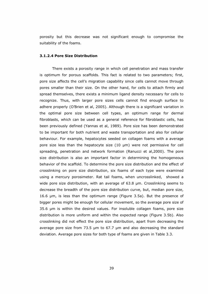
39
porosity but this decrease was not significant enough to compromise the
suitability of the foams.
3.1.2.4 Pore Size Distribution
There exists a porosity range in which cell penetration and mass transfer
is optimum for porous scaffolds. This fact is related to two parameters; first,
pore size affects the cell�s migration capability since cells cannot move through
pores smaller than their size. On the other hand, for cells to attach firmly and
spread themselves, there exists a minimum ligand density necessary for cells to
recognize. Thus, with larger pore sizes cells cannot find enough surface to
adhere properly (O�Brien et al, 2005). Although there is a significant variation in
the optimal pore size between cell types, an optimum range for dermal
fibroblasts, which can be used as a general reference for fibroblastic cells, has
been previously defined (Yannas et al, 1989). Pore size has been demonstrated
to be important for both nutrient and waste transportation and also for cellular
behaviour. For example, hepatocytes seeded on collagen foams with a average
pore size less than the hepatocyte size (10 µm) were not permissive for cell
spreading, penetration and network formation (Ranucci et al,2000). The pore
size distribution is also an important factor in determining the homogeneous
behavior of the scaffold. To determine the pore size distribution and the effect of
crosslinking on pore size distribution, six foams of each type were examined
using a mercury porosimeter. Rat tail foams, when uncrosslinked, showed a
wide pore size distribution, with an average of 63.8 µm. Crosslinking seems to
decrease the breadth of the pore size distribution curve, but, median pore size,
16.6 µm, is less than the optimum range (Figure 3.5a). But the presence of
bigger pores might be enough for cellular movement, so the average pore size of
35.6 µm is within the desired values. For insoluble collagen foams, pore size
distribution is more uniform and within the expected range (Figure 3.5b). Also
crosslinking did not effect the pore size distribution, apart from decreasing the
average pore size from 73.5 µm to 67.7 µm and also decreasing the standard
deviation. Average pore sizes for both type of foams are given in Table 3.3.

40
0
2
4
6
8
10
12
14
16
48,2
13,3 20 35 50
83,3
133,
320
0
Pore size, micrometers
Perc
enta
ge,
%
IS UXL
ISXL
ISdeg2weeks
a)
b)
Figure 3.5 Pore size distribution of a) Crosslinked and uncrosslinked rat tail
collagen foams, b) Crosslinked, uncrosslinked and crosslinked-degraded for two
weeks in situ insoluble collagen foams.
0
5
10
15
20
25
48,
213
,3 20 35 5083
,3
133,
320
0
Pore size, micrometers
Perc
enta
ge,
%Uncrosslinked RT foam
Crosslinked RT foam
41
Table 3.4 Average pore size of rat tail and insoluble collagen foams.
Average Pore size (µm)
Treatment
Rat tail collagen foam Insoluble collagen foam
Uncrosslinked 63.8 73.5
Crosslinked 35.6 67.7
Degradation (2 weeks) - 74.0
3.2 Degradation Profiles of the Scaffolds
For integration of a tissue engineered product with the host, rate of
degradation and the effect of degradation on carrier properties are of utmost
importance. The scaffold should degrade neither too slow nor too fast, since fast
degradation compromises structural stability and slow degradation prevents
remodeling, thus decreasing the effectiveness of the scaffold (Pek et al, 2004).
Scaffold degradation studies were carried out for a month at 37 °C in PBS (pH
7.4, 10 mM). During this period, the films lost up to 50% of their initial weight.
Among the foams there seems to be no significant difference. Both behave in a
bi-phasic manner with a total weight loss of ca. 70% in 4 weeks (Figures 3.6).
There was a small but steady decrease in pH of the medium, all solutions ending
up slightly acidic in 4 weeks due to the formation of acidic groups as a result of
degradation (Figures 3.7).

42
Figure 3.6 Weight loss of collagen scaffolds over the course of 4 weeks at 37°C
in PBS (pH 7.4, 10 mM).
Figure 3.7 pH change of the degradation medium over the course of a 4-week
incubation at 37 °C in PBS (pH 7.4, 10 mM).
0
10
20
30
40
50
60
70
80
0 0.5 1 1.5 2 2.5 3 3.5 4 4.5
Time (weeks)
Wei
ght
Loss
(%
)
Collagen films
RT foams
IS foams
6.4
6.6
6.8
7
7.2
7.4
7.6
0 1 2 3 4
Time (weeks)
pH
Collagen films
IS collagen foams
RT foams
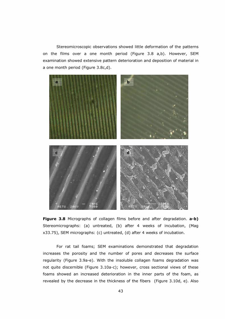
43
dc
b
Stereomicroscopic observations showed little deformation of the patterns
on the films over a one month period (Figure 3.8 a,b). However, SEM
examination showed extensive pattern deterioration and deposition of material in
a one month period (Figure 3.8c,d).
Figure 3.8 Micrographs of collagen films before and after degradation. a-b)
Stereomicrographs: (a) untreated, (b) after 4 weeks of incubation, (Mag
x33.75), SEM micrographs: (c) untreated, (d) after 4 weeks of incubation.
For rat tail foams; SEM examinations demonstrated that degradation
increases the porosity and the number of pores and decreases the surface
regularity (Figure 3.9a-e). With the insoluble collagen foams degradation was
not quite discernible (Figure 3.10a-c); however, cross sectional views of these
foams showed an increased deterioration in the inner parts of the foam, as
revealed by the decrease in the thickness of the fibers (Figure 3.10d, e). Also
a

44
mercury porosimetry measurement after 2 weeks of degradation showed a small
increase in the average pore size, from 67.7 µm to 74 µm (Figure 3.5b).
Figure 3.9 SEM micrographs of rat tail collagen foam. a) Week 0, b) Week 2, c)
Week 4, d) Week 2 higher magnification, e) Week 4 higher magnification.
a
b c
d e
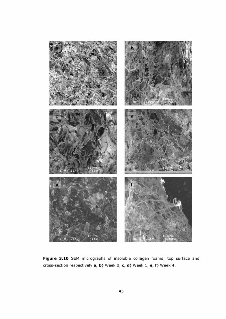
45
Figure 3.10 SEM micrographs of insoluble collagen foams; top surface and
cross-section respectively a, b) Week 0, c, d) Week 1, e, f) Week 4.
d
b
e f
a
c
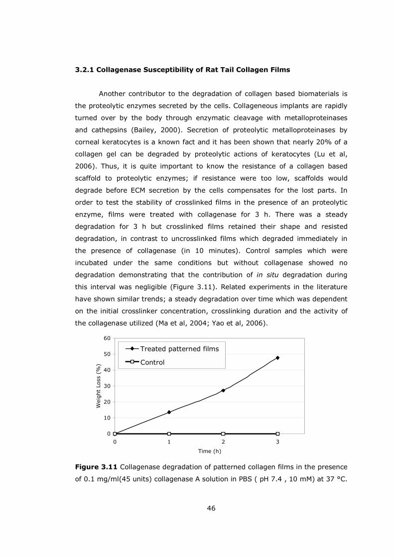
46
3.2.1 Collagenase Susceptibility of Rat Tail Collagen Films
Another contributor to the degradation of collagen based biomaterials is
the proteolytic enzymes secreted by the cells. Collageneous implants are rapidly
turned over by the body through enzymatic cleavage with metalloproteinases
and cathepsins (Bailey, 2000). Secretion of proteolytic metalloproteinases by
corneal keratocytes is a known fact and it has been shown that nearly 20% of a
collagen gel can be degraded by proteolytic actions of keratocytes (Lu et al,
2006). Thus, it is quite important to know the resistance of a collagen based
scaffold to proteolytic enzymes; if resistance were too low, scaffolds would
degrade before ECM secretion by the cells compensates for the lost parts. In
order to test the stability of crosslinked films in the presence of an proteolytic
enzyme, films were treated with collagenase for 3 h. There was a steady
degradation for 3 h but crosslinked films retained their shape and resisted
degradation, in contrast to uncrosslinked films which degraded immediately in
the presence of collagenase (in 10 minutes). Control samples which were
incubated under the same conditions but without collagenase showed no
degradation demonstrating that the contribution of in situ degradation during
this interval was negligible (Figure 3.11). Related experiments in the literature
have shown similar trends; a steady degradation over time which was dependent
on the initial crosslinker concentration, crosslinking duration and the activity of
the collagenase utilized (Ma et al, 2004; Yao et al, 2006).
Figure 3.11 Collagenase degradation of patterned collagen films in the presence
of 0.1 mg/ml(45 units) collagenase A solution in PBS ( pH 7.4 , 10 mM) at 37 °C.
0
10
20
30
40
50
60
0 1 2 3
Time (h)
Wei
ght
Loss
(%
)
Treated patterned films
Control

47
0
50000
100000
150000
200000
250000
300000
0 2 4 6 8 10 12
Time (days)
Cell N
um
ber
Collagen films
TCP
3.3 Cell Proliferation
Cell proliferation was determined with the MTS assay. In order to be able
to determine the cell growth rate accurately, a small initial number of cells (1 x
104) was chosen. For films the number of cells reached 1.76 x10⁵ in 10 days, an
increase of 18 fold (Figure 3.12). This might be close to the limit for the cell
number on collagen films (confluency) since in tissue culture flasks when
confluent there are around 1.6x10⁵ cells/cm2. Due to the presence of patterns,
the film structure is not exactly two dimensional and the presence of the
patterns increases the overall surface area. With a higher seeding density to
observe the relation between the increase in mechanical strength and cell
number, 2.60x10⁵ cells were reached after a period of 3 weeks (Figure 3.13).
This higher number can be attributed to the faster proliferation in the beginning
leading to a more excessive ECM secretion which provides more surface for cells
thus increasing the available area, which was also observed by fluorescence
microscopy.
Figure 3.12 Proliferation of keratocytes on patterned collagen films. (Initial
seeding number per sample 1 x 10⁴ )

48
0
50000
100000
150000
200000
250000
300000
0 5 10 15 20 25
Time (days)
Cel
l N
um
ber
Figure 3.13 Proliferation of keratocytes on patterned collagen films in a 3 weeks
period. (Initial seeding number per sample: 5 x 10⁴)
In Figure 3.14, it is observed that cell number on TCP was 3.0 x 10⁵ ± 2.3
x 103 on day 10. A single well of a 24-well of a TCP has an area of 2.54 cm2
and the density of cells at confluency in this well is 1.6x10⁵ cells/cm2 as found by
cell counter. Thus, in a well at confluency 4 x10⁵ cells should be found. This
number is slightly higher than the MTS results, however MTS results are in
agreement with that obtained in previous studies where with a similar growth
curve, the cell number per well was found to be around 3x10⁵ at the end of one
week (Pancholi et al, 1998). For foams, cell numbers reached on day 10 were
2.8 x 10⁵ ± 1.2 x 10⁴ and 2.0 x 10⁵ ± 4.8 x 10³ for rat tail collagen and insoluble
collagen foams, respectively. In another study, with bovine hide collagen
sponges, cell number after a 10 day period was around 4 x10⁵ cell per foam,
even though these foams were thicker than the one used in these experiments
(thickness 1.2 mm compared to 0.532 mm and 0.811 mm respectively; Orwel et
al, 2003). Foams can be expected to accommodate higher numbers of cells;
however, their low thicknesses restricts the available volume for cell attachment
and proliferation. Also a 50% surface porosity may cause a lag in penetration of
the cells and an overall obstacle to the transport of nutrients and oxygen.
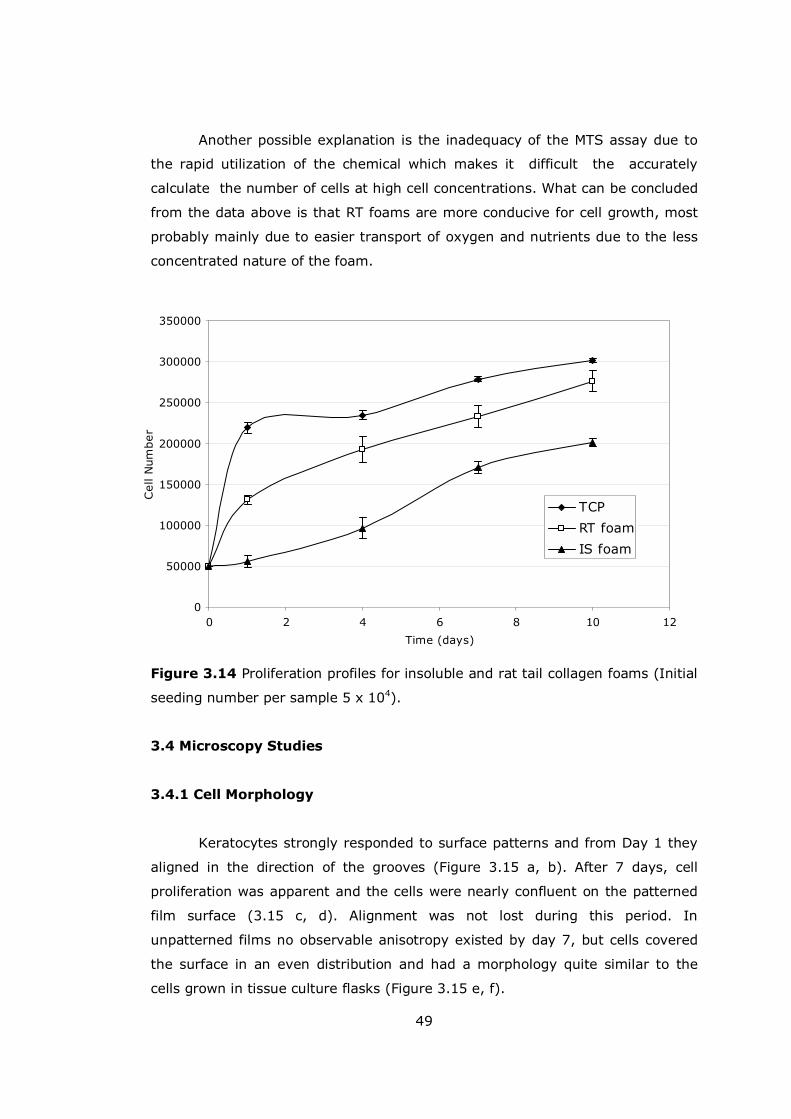
49
0
50000
100000
150000
200000
250000
300000
350000
0 2 4 6 8 10 12
Time (days)
Cell
Num
ber
TCP
RT foam
IS foam
Another possible explanation is the inadequacy of the MTS assay due to
the rapid utilization of the chemical which makes it difficult the accurately
calculate the number of cells at high cell concentrations. What can be concluded
from the data above is that RT foams are more conducive for cell growth, most
probably mainly due to easier transport of oxygen and nutrients due to the less
concentrated nature of the foam.
Figure 3.14 Proliferation profiles for insoluble and rat tail collagen foams (Initial
seeding number per sample 5 x 10⁴).
3.4 Microscopy Studies
3.4.1 Cell Morphology
Keratocytes strongly responded to surface patterns and from Day 1 they
aligned in the direction of the grooves (Figure 3.15 a, b). After 7 days, cell
proliferation was apparent and the cells were nearly confluent on the patterned
film surface (3.15 c, d). Alignment was not lost during this period. In
unpatterned films no observable anisotropy existed by day 7, but cells covered
the surface in an even distribution and had a morphology quite similar to the
cells grown in tissue culture flasks (Figure 3.15 e, f).
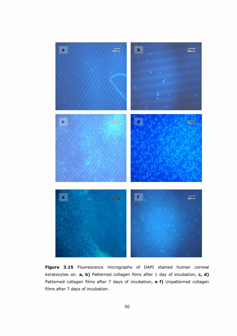
50
Figure 3.15 Fluorescence micrographs of DAPI stained human corneal
keratocytes on: a, b) Patterned collagen films after 1 day of incubation, c, d)
Patterned collagen films after 7 days of incubation, e f) Unpatterned collagen
films after 7 days of incubation.
a b
c d
e f

51
Loss of alignment was observed in some parts of the films but even after
21 days of culture alignment still persisted (Figure 3.16 a-d).
Figure 3.16 Fluorescence micrographs of Acridine orange stained human
corneal keratocytes on patterned collagen films after a) 1 day, b) 7 days, c) 14
days, d) 21 days of incubation.
Some cells seemed to migrate out of the grooves and appeared out of
focus since they were at higher elevations than most cells. Cells could both grow
and move on the inclined surfaces of the groove and the second reason for such
behavior could be the excessive secretion of ECM molecules as a response to the
presence of the patterns, filling up the grooves and allowing cells to occupy
positions higher than the patterns would normally allow. SEM micrographs
supported this explanation. They showed individual cells on day 7 (Figure 3.17a,
b), but by day 14 single cells can not be discerned and the surface had a more
a b
c d
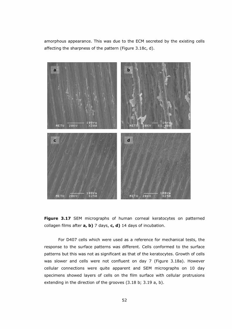
52
amorphous appearance. This was due to the ECM secreted by the existing cells
affecting the sharpness of the pattern (Figure 3.18c, d).
Figure 3.17 SEM micrographs of human corneal keratocytes on patterned
collagen films after a, b) 7 days, c, d) 14 days of incubation.
For D407 cells which were used as a reference for mechanical tests, the
response to the surface patterns was different. Cells conformed to the surface
patterns but this was not as significant as that of the keratocytes. Growth of cells
was slower and cells were not confluent on day 7 (Figure 3.18a). However
cellular connections were quite apparent and SEM micrographs on 10 day
specimens showed layers of cells on the film surface with cellular protrusions
extending in the direction of the grooves (3.18 b; 3.19 a, b).
a b
c d
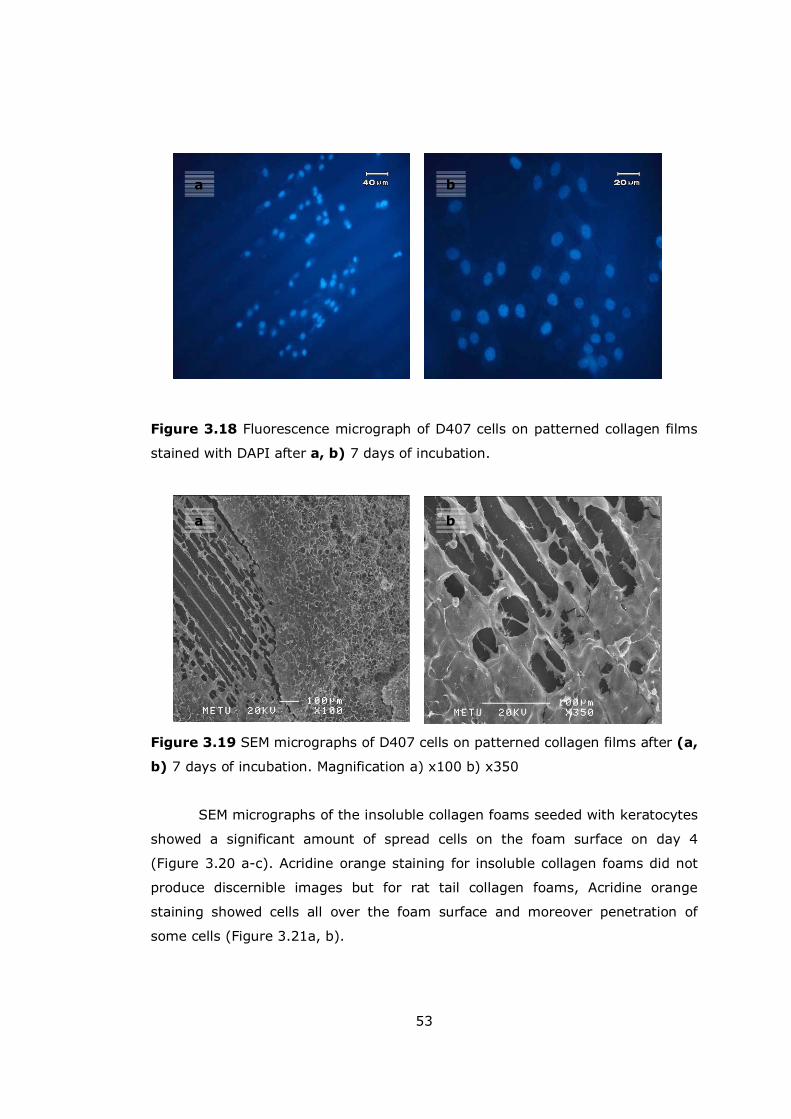
53
a b
a b
Figure 3.18 Fluorescence micrograph of D407 cells on patterned collagen films
stained with DAPI after a, b) 7 days of incubation.
Figure 3.19 SEM micrographs of D407 cells on patterned collagen films after (a,
b) 7 days of incubation. Magnification a) x100 b) x350
SEM micrographs of the insoluble collagen foams seeded with keratocytes
showed a significant amount of spread cells on the foam surface on day 4
(Figure 3.20 a-c). Acridine orange staining for insoluble collagen foams did not
produce discernible images but for rat tail collagen foams, Acridine orange
staining showed cells all over the foam surface and moreover penetration of
some cells (Figure 3.21a, b).
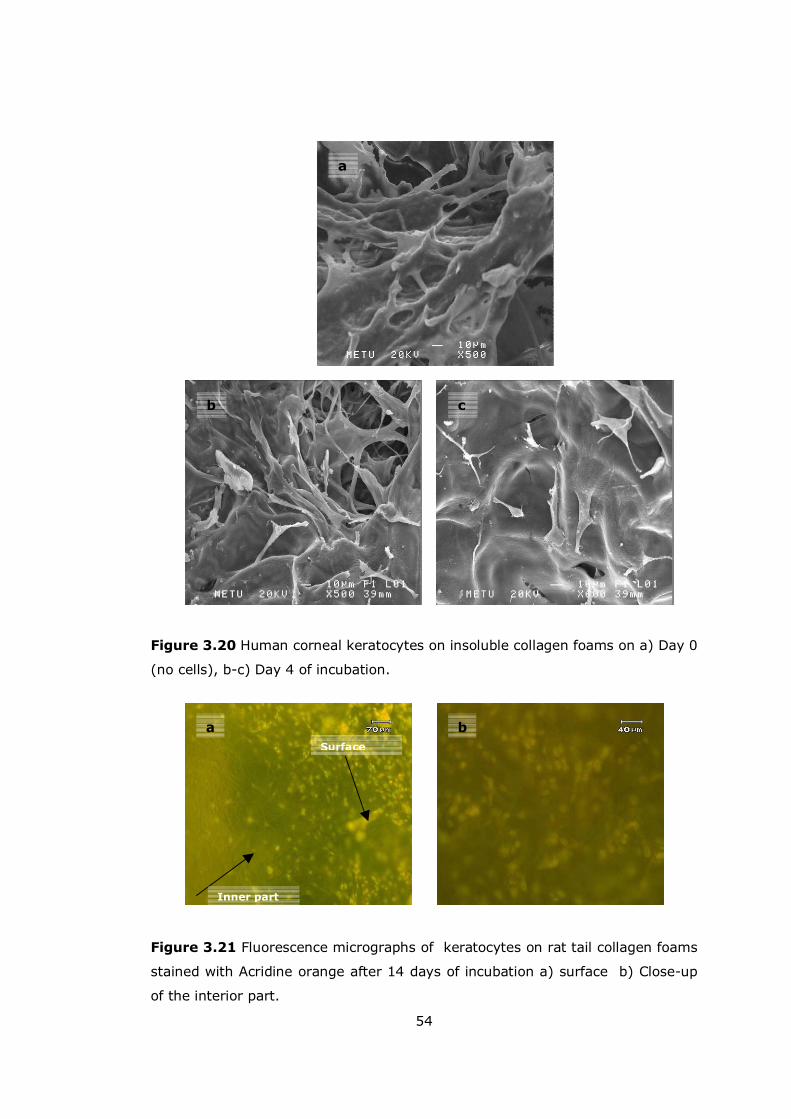
54
Figure 3.20 Human corneal keratocytes on insoluble collagen foams on a) Day 0
(no cells), b-c) Day 4 of incubation.
Figure 3.21 Fluorescence micrographs of keratocytes on rat tail collagen foams
stained with Acridine orange after 14 days of incubation a) surface b) Close-up
of the interior part.
b
a
c
Surface
Inner part
a b
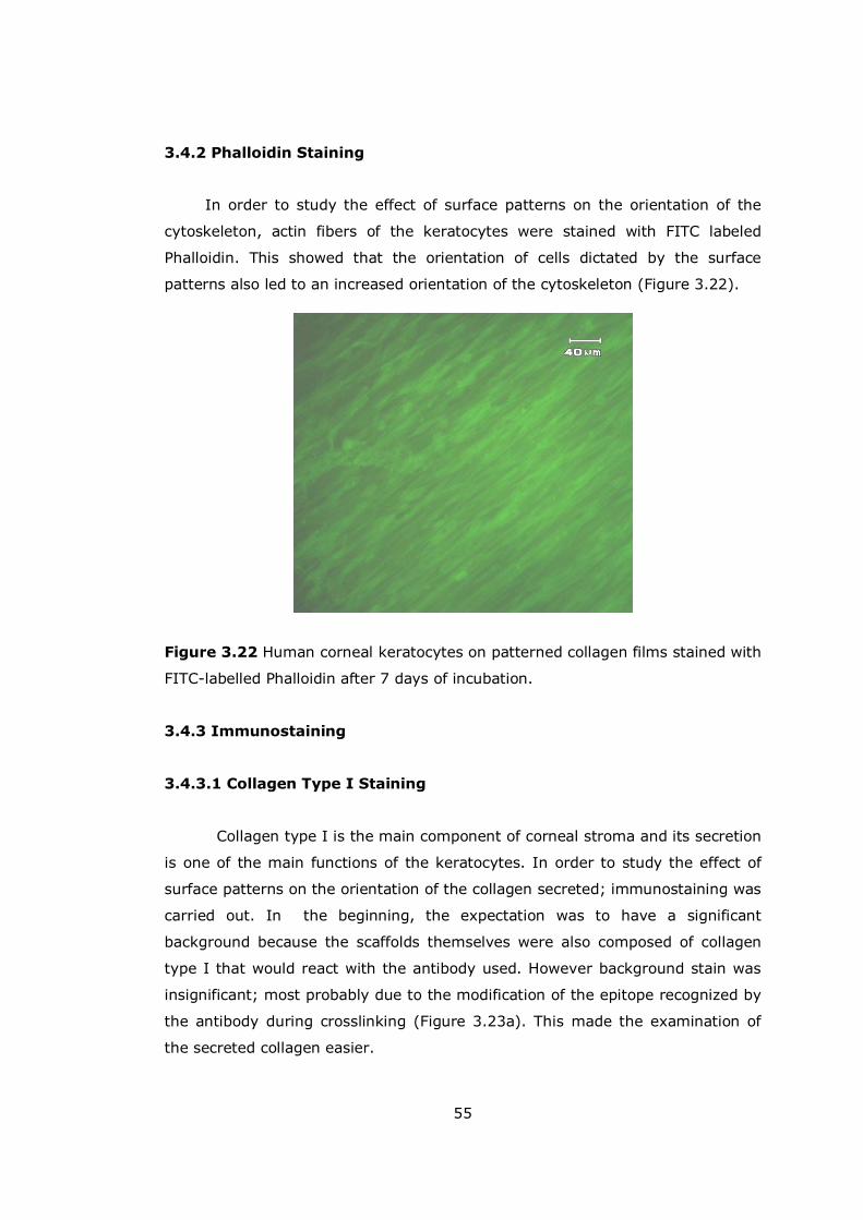
55
3.4.2 Phalloidin Staining
In order to study the effect of surface patterns on the orientation of the
cytoskeleton, actin fibers of the keratocytes were stained with FITC labeled
Phalloidin. This showed that the orientation of cells dictated by the surface
patterns also led to an increased orientation of the cytoskeleton (Figure 3.22).
Figure 3.22 Human corneal keratocytes on patterned collagen films stained with
FITC-labelled Phalloidin after 7 days of incubation.
3.4.3 Immunostaining
3.4.3.1 Collagen Type I Staining
Collagen type I is the main component of corneal stroma and its secretion
is one of the main functions of the keratocytes. In order to study the effect of
surface patterns on the orientation of the collagen secreted; immunostaining was
carried out. In the beginning, the expectation was to have a significant
background because the scaffolds themselves were also composed of collagen
type I that would react with the antibody used. However background stain was
insignificant; most probably due to the modification of the epitope recognized by
the antibody during crosslinking (Figure 3.23a). This made the examination of
the secreted collagen easier.
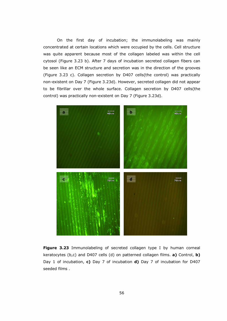
56
On the first day of incubation; the immunolabeling was mainly
concentrated at certain locations which were occupied by the cells. Cell structure
was quite apparent because most of the collagen labeled was within the cell
cytosol (Figure 3.23 b). After 7 days of incubation secreted collagen fibers can
be seen like an ECM structure and secretion was in the direction of the grooves
(Figure 3.23 c). Collagen secretion by D407 cells(the control) was practically
non-existent on Day 7 (Figure 3.23d). However, secreted collagen did not appear
to be fibrillar over the whole surface. Collagen secretion by D407 cells(the
control) was practically non-existent on Day 7 (Figure 3.23d).
Figure 3.23 Immunolabeling of secreted collagen type I by human corneal
keratocytes (b,c) and D407 cells (d) on patterned collagen films. a) Control, b)
Day 1 of incubation, c) Day 7 of incubation d) Day 7 of incubation for D407
seeded films .
a b
c d

57
In the keratocyte seeded unpatterned film samples, collagen secretion
seemed to be less with respect to the patterned counterparts and as expected
there was no sign of anisotropy (Figure 3.24).
Figure 3.24 Immunostaining of collagen type I secreted by keratocytes on
unpatterned collagen films after 7 days of incubation.
3.4.3.2 Keratan Sulfate Staining
Keratan sulfate is a glycosaminoglycan and is an essential component of
the corneal stroma structure. It is found in three corneal proteoglycans (lumican,
keratocan and mimecan) and is responsible of the hydration of the stroma and
the orientation of the collagen fibers (Funderburgh et al, 2003). Thus it
contributes to corneal transparency. These proteoglycans are quite oriented,
surrounding the individual collagen fibers. They are also secreted by the
keratocytes and their presence is an indicator of the proper keratocyte behavior
(Funderburgh, 2000). Hence, both patterned and unpatterned films were seeded
with keratocytes and stained for keratan sulfate secretion. Secretion was
observed in both specimens on Day 1 and Day 7 (Figure 3.25a-d). As with
collagen type I, secretion conformed to the patterns of the films but there was
no orientation in unpatterned ones.

58
Figure 3.25 Keratan sulfate staining for keratocytes seeded on a-b) unpatterned
Day 1 and Day 7, c-d) Patterned films Day 1 and Day 7 samples, respectively.
3.4.4 Confocal Microscopy (CLSM)
Confocal studies were carried out to study the mobility of the cells and
obtain proof of penetration into the foams and also to see the distribution of the
secreted collagen. Confocal images of RT foams showed spread cells within the
100 micrometer depth of the scaffolds (Figure 3.26 a,b).
a b
c d

59
Spread cells were also observed within the insoluble collagen foams, the
cross-sections revealed that cells have moved to the edges; but not in a
homogenous manner ( Figure 3.27 a-c)
Figure 3.26 CLSM images of Acridine orange stained keratocyte seeded rat tail
collagen foams after 15 days a) Distribution of spread cells inside the foam; cells
were seeded from the right hand side (Magnification x40) b) Distribution of the
keratocytes in lateral direction and penetration of the cells inside the foam,
thickness 100 µm; cells were seeded from the top (Magnification x10).
a
b
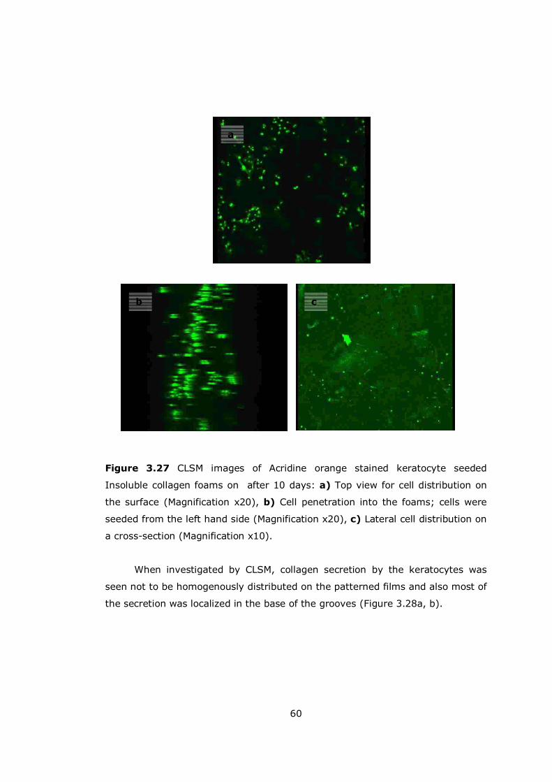
60
Figure 3.27 CLSM images of Acridine orange stained keratocyte seeded
Insoluble collagen foams on after 10 days: a) Top view for cell distribution on
the surface (Magnification x20), b) Cell penetration into the foams; cells were
seeded from the left hand side (Magnification x20), c) Lateral cell distribution on
a cross-section (Magnification x10).
When investigated by CLSM, collagen secretion by the keratocytes was
seen not to be homogenously distributed on the patterned films and also most of
the secretion was localized in the base of the grooves (Figure 3.28a, b).
a
cb

61
Figure 3.28 Confocal images of collagen type I immunostaining after 7 days of
incubation. Magnification a) x 10, b) x 40 focused on the base of the grooves.
3.5 Mechanical tests
Cornea withstands the shear forces exerted by the tear film and by the
eyelids and also ensures the constant inner hydrodynamic pressure. To this end,
the structure of the corneal stroma is important and any attempt to simulate
corneal stroma should take into account this property. As described earlier,
patterned collagen films are quite good at orienting cells and ECM materials; but
they were susceptible to collagenase activity and were also shown to degrade
through erosion as shown by the in situ degradation experiments (Section 3.4).
Thus, the mechanical strength of the films, in the presence and absence of the
cells, was quite important and in order to see the effect of the cell type, D407
cells were used as a reference, a model epithelial layer. There were three groups
of specimens: a) unseeded films, b) films seeded with keratocytes and c) films
seeded with D407 cells. These samples were incubated for time periods of 1, 2
and 3 weeks in the cell culture and their tensile strength was determined.
The mechanical strength of the unseeded samples decreased significantly
after the first week, followed by less prominent decreases in the following weeks
(Figure 3.29a). This correlates well with the leveling out of the degradation after
two weeks. The only thing that should be considered while doing such a
comparison was the presence of the serum proteins that can get absorbed onto
a b
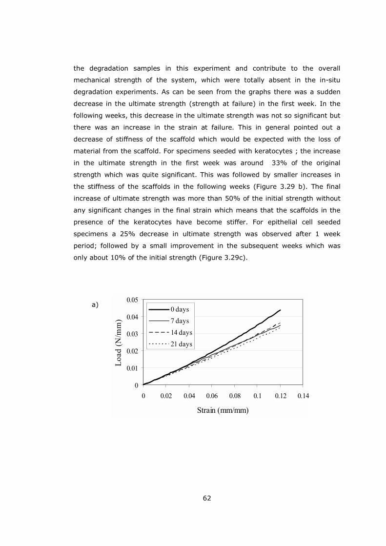
62
0
0.01
0.02
0.03
0.04
0.05
0 0.02 0.04 0.06 0.08 0.1 0.12 0.14
Strain (mm/mm)
Load
(N/m
m)
0 days7 days14 days21 days
the degradation samples in this experiment and contribute to the overall
mechanical strength of the system, which were totally absent in the in-situ
degradation experiments. As can be seen from the graphs there was a sudden
decrease in the ultimate strength (strength at failure) in the first week. In the
following weeks, this decrease in the ultimate strength was not so significant but
there was an increase in the strain at failure. This in general pointed out a
decrease of stiffness of the scaffold which would be expected with the loss of
material from the scaffold. For specimens seeded with keratocytes ; the increase
in the ultimate strength in the first week was around 33% of the original
strength which was quite significant. This was followed by smaller increases in
the stiffness of the scaffolds in the following weeks (Figure 3.29 b). The final
increase of ultimate strength was more than 50% of the initial strength without
any significant changes in the final strain which means that the scaffolds in the
presence of the keratocytes have become stiffer. For epithelial cell seeded
specimens a 25% decrease in ultimate strength was observed after 1 week
period; followed by a small improvement in the subsequent weeks which was
only about 10% of the initial strength (Figure 3.29c).
a)
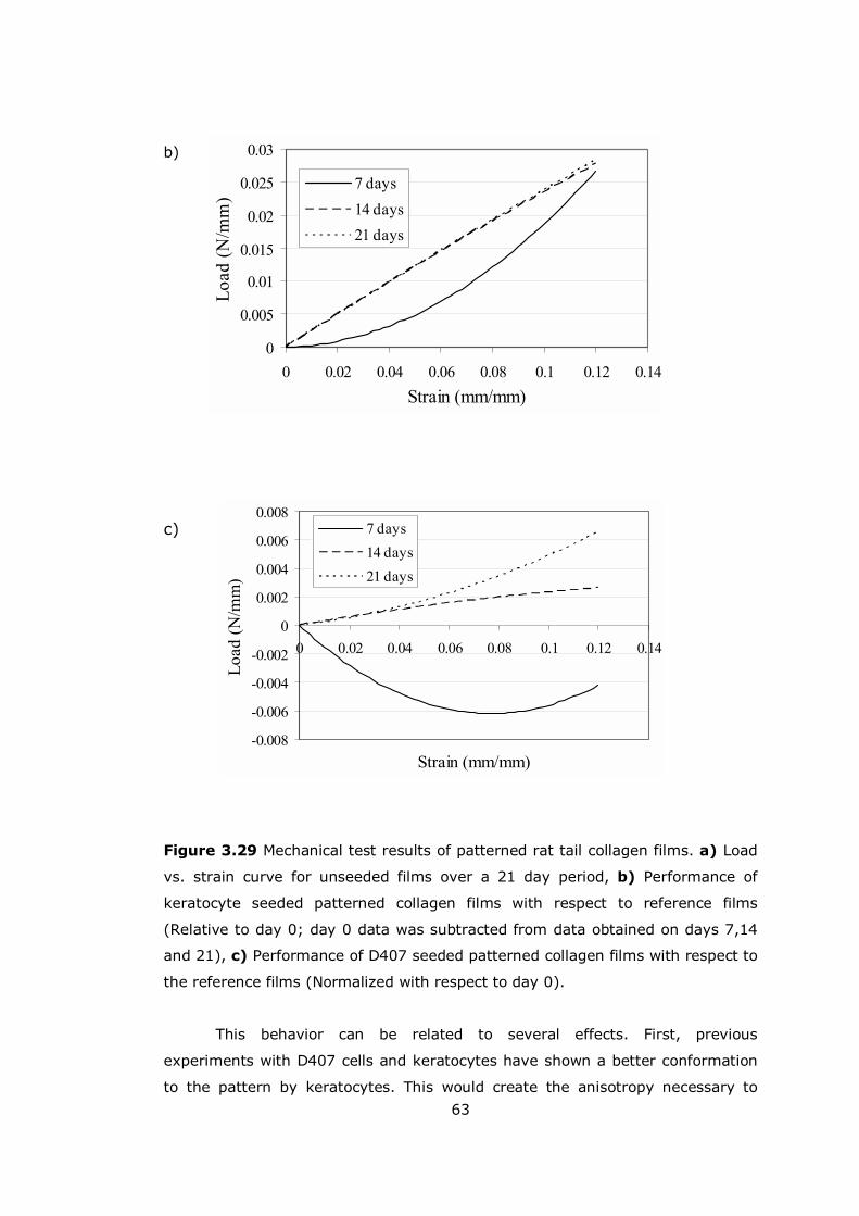
63
-0.008
-0.006
-0.004
-0.002
0
0.002
0.004
0.006
0.008
0 0.02 0.04 0.06 0.08 0.1 0.12 0.14
Strain (mm/mm)
Load
(N/m
m)
7 days14 days21 days
0
0.005
0.01
0.015
0.02
0.025
0.03
0 0.02 0.04 0.06 0.08 0.1 0.12 0.14Strain (mm/mm)
Load
(N/m
m)
7 days14 days21 days
b)
c)
Figure 3.29 Mechanical test results of patterned rat tail collagen films. a) Load
vs. strain curve for unseeded films over a 21 day period, b) Performance of
keratocyte seeded patterned collagen films with respect to reference films
(Relative to day 0; day 0 data was subtracted from data obtained on days 7,14
and 21), c) Performance of D407 seeded patterned collagen films with respect to
the reference films (Normalized with respect to day 0).
This behavior can be related to several effects. First, previous
experiments with D407 cells and keratocytes have shown a better conformation
to the pattern by keratocytes. This would create the anisotropy necessary to

64
create an improvement in tensile strength in that axis, since loading was parallel
to the groove direction. Also D407 cells were lower in number by day 7; so this
might be another factor. The smaller increase in weeks 2 and 3 can be related to
the decreasing rate of cell growth confirmed by the MTS results. The patterned
surface would help the increase in tensile strength in the direction parallel to the
patterns, since it would provide necessary cues that would direct cell,
cytoskeleton and extracellular matrix arrangement as shown by the
immunolabelling above. Thus oriented collagen type I and keratan sulfate
secretion would provide the necessary compensation against the activity of
secreted collagenase enzymes and also degradation by erosion. The same is not
true for D407 cells, since their extracellular matrix secretion is limited and they
have a higher collagenase activity. Since endurance of the films to collagenase
activity was not high, low cell density and insufficient ECM would not be enough
to compensate the degradation of the films, which would explain the decrease in
strength. However as all epithelial cells they tend to establish strong cell to cell
connections which could be the reason for the rectification of the mechanical
strength of the films after 2 weeks and in the long run may result in an
hyperelastic behavior of the scaffolds.
3.6 Transparency Measurements
Transparency is one of the most important properties of the cornea and
it should be regained for an artificial cornea implantation to be considered
successful. It is, therefore important to investigate the in vitro transparency for
any artificial cornea product. In order to study this, patterned and unpatterned
films seeded with keratocytes and cell-free patterned films were tested for their
transparency of light in the UV-VIS range over 7 days. In addition to films,
foams seeded with keratocytes were also tested for their transparency after one
week.
Initially patterned and unpatterned films have a 30% percent
transmittance of the incoming visible light, with unpatterned films being slightly
more transparent (Figure 3.30 a). Transparency of the unseeded patterned films
increased and at the 7th day reached about 40 % (Figure 3.30 b-d). Patterned
collagen films seeded with keratocytes showed a consistent transparency over
this period after an initial slight decline (Figure 3.30 b-d). On the other hand,
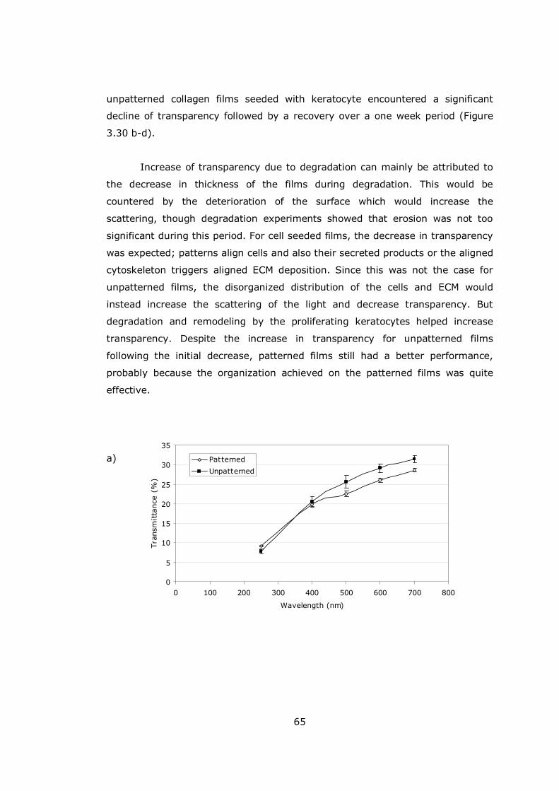
65
0
5
10
15
20
25
30
35
0 100 200 300 400 500 600 700 800
Wavelength (nm)
Tran
smitta
nce
(%
)
Patterned
Unpatterned
unpatterned collagen films seeded with keratocyte encountered a significant
decline of transparency followed by a recovery over a one week period (Figure
3.30 b-d).
Increase of transparency due to degradation can mainly be attributed to
the decrease in thickness of the films during degradation. This would be
countered by the deterioration of the surface which would increase the
scattering, though degradation experiments showed that erosion was not too
significant during this period. For cell seeded films, the decrease in transparency
was expected; patterns align cells and also their secreted products or the aligned
cytoskeleton triggers aligned ECM deposition. Since this was not the case for
unpatterned films, the disorganized distribution of the cells and ECM would
instead increase the scattering of the light and decrease transparency. But
degradation and remodeling by the proliferating keratocytes helped increase
transparency. Despite the increase in transparency for unpatterned films
following the initial decrease, patterned films still had a better performance,
probably because the organization achieved on the patterned films was quite
effective.
a)
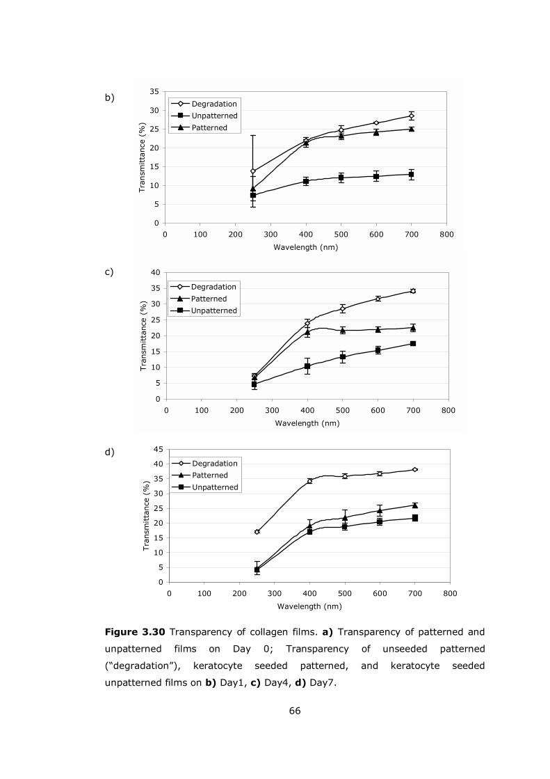
66
0
5
10
15
20
25
30
35
0 100 200 300 400 500 600 700 800
Wavelength (nm)
Tran
smitta
nce
(%
)
Degradation
Unpatterned
Patterned
0
5
10
15
20
25
30
35
40
0 100 200 300 400 500 600 700 800
Wavelength (nm)
Tra
nsm
itta
nce
(%
)
Degradation
Patterned
Unpatterned
0
5
10
15
20
25
30
35
40
45
0 100 200 300 400 500 600 700 800
Wavelength (nm)
Tra
nsm
itta
nce
(%
)
Degradation
Patterned
Unpatterned
b)
c)
d)
Figure 3.30 Transparency of collagen films. a) Transparency of patterned and
unpatterned films on Day 0; Transparency of unseeded patterned
(�degradation�), keratocyte seeded patterned, and keratocyte seeded
unpatterned films on b) Day1, c) Day4, d) Day7.
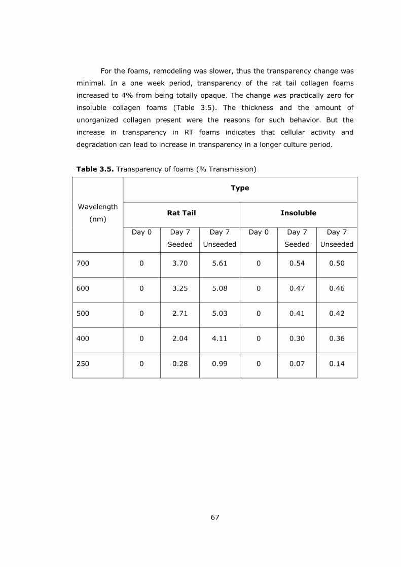
67
For the foams, remodeling was slower, thus the transparency change was
minimal. In a one week period, transparency of the rat tail collagen foams
increased to 4% from being totally opaque. The change was practically zero for
insoluble collagen foams (Table 3.5). The thickness and the amount of
unorganized collagen present were the reasons for such behavior. But the
increase in transparency in RT foams indicates that cellular activity and
degradation can lead to increase in transparency in a longer culture period.
Table 3.5. Transparency of foams (% Transmission)
Type
Rat Tail Insoluble
Wavelength
(nm)
Day 0 Day 7
Seeded
Day 7
Unseeded
Day 0 Day 7
Seeded
Day 7
Unseeded
700 0 3.70 5.61 0 0.54 0.50
600 0 3.25 5.08 0 0.47 0.46
500 0 2.71 5.03 0 0.41 0.42
400 0 2.04 4.11 0 0.30 0.36
250 0 0.28 0.99 0 0.07 0.14

68
CHAPTER 4
CONCLUSION
A tissue engineered cornea must satisfy several requirements. It should
be biodegradable, should have a certain thickness, must be conducive to the
proliferation of corneal cells, should be strong enough to withstand intraocular
pressure and other forces exerted on the natural cornea, and it must be
transparent. In this study, collagen was selected as the scaffold material, since it
is one of the major constituents of the natural cornea and also as a natural
polymer it is biodegradable and biocompatible. In this study 3 scaffolds were
produced, insoluble collagen foams, rat tail collagen foams, and micropatterned
rat tail collagen films using 2 different collagen sources, insoluble collagen from
bovine trachea, and rat tail collagen.
Foams are very appropriate structures for cornea reconstruction; they are
highly porous, thus they permit cell penetration and also allow transfer of
nutrients and wastes. Physical characterization of both of these foams showed
that bulk porosity and average pore size of these foams are appropriate for
cellular penetration. A skin layer was however observed in insoluble collagen
foams formed during the freeze-drying procedure. Another problem associated
with the collagen foams was the preservation of the initial thickness of the foams
following stabilization (e.g. crosslinking) procedures. This was not very
significant with insoluble collagen foams, for which shrinkage was not extensive.
Rat tail collagen foams, however, lost their porosity and thickness following the
conventional crosslinking procedure. Thus, a novel crosslinking procedure was
developed to maintain the thickness of these foams. With this technique, foams
which have a thickness very close to that of the native cornea.
69
In vitro studies carried out with human corneal keratocytes demonstrated
that both foams were appropriate for keratocyte growth. Quantitative studies
showed that rat tail collagen foams reached a higher final cell number and
density. Microscopy studies have shown that cells spread on the surface and
penetrated into the interior regions of the foams.
Cornea has a very unique structure. The orientation of the collagen fibrils
in the corneal stroma is essential for proper functioning of the cornea. Since
transparency and mechanical properties of the cornea are dependent on this
architecture, the utilization of micropatterned surfaces to guide cellular behavior
and to mimic native corneal organization was deemed beneficial. Hence, possible
benefits of incorporation of micropatterned surfaces in artificial cornea design
were investigated by using collagen films with micro-level patterns in the form of
channels with sloping sides and narrow ridges. Human corneal keratocytes grew
on these patterned collagen films in a fast rate and they conformed to the
surface patterns and elongated in the groove direction as confirmed by
quantitative MTS assay and microscopy observations. The presence of the
patterns also affected the ECM secretion and cytoskelatal orientation and these
features were observed with immunostaining. These experiments showed that
keratocytes on patterned collagen films secreted oriented collagen type I and
keratan sulfate in contrast to unpatterned collagen films in which secretion was
random.
Degradation and remodeling of the scaffolds by the cells in in vivo
conditions is very important for the successful integration of the artificial tissue
to the host. Thus, in situ degradation studies were carried out with both foams.
Foams degraded with a steady pace without losing their structural integrity for a
month. Microscopy revealed an increase in the pore size and a more
disorganized appearance following degradation.
In situ degradation experiments were also done with patterned collagen
films and they showed a degradation pattern similar to that of collagen foams.
Surface patterns were still visible but quite deteriorated after a 1 month
incubation period. In addition to these resistance of the collagen films to
collagenase activity which is known to be secreted by the keratocytes during
remodeling of the cornea was studied. Stabilization of the films with EDC/NHS
70
crosslinking increased the resistance of the films to collagenase activity
significantly.
In order to see the effects of degradation and the presence of the
keratocytes on the mechanical properties of the patterned collagen films, tensile
strength tests were performed on unseeded films as well as on films seeded with
keratocytes and with D407 epithelial cells (D407 were used as a reference for a
three week period). These experiments showed that the presence of the
keratocytes on the films compensated for the decrease in the strength of the
carrier due to hydrolytic degradation. This was probably due to the alignment of
the cells on the surface and secretion of the ECM components oriented along the
pattern axis. Meanwhile, the mechanical strength of the cell-free films decreased
during the experiments. Similarly, films seeded with D407 cells did not show any
improvement (actually, a major loss of mechanical property was observed in the
early days of incubation). These results were very promising for the suitability of
collagen film scaffolds in vivo.
The most crucial feature of the oriented corneal stroma structure is its
role in corneal transparency. Organization of collagen fibrils and proteoglycans is
essential for corneal transparency. In order to see whether the organization
achieved by the micropatterned films had a similar effect or not, transparency of
the patterned collagen films was measured both in the presence and absence of
keratocytes and compared to the transparency of unpatterned collagen films
seeded with keratocytes. Transparency of unseeded films increased steadily over
an one week period. Transparency of keratocyte seeded patterned films
decreased slightly after seeding but stayed at the same level for the duration of
the experiment. For unpatterned films seeded with keratocytes, there was a
significant decrease in transparency after seeding and although transparency
improved afterwards it did not reach to the level of patterned collagen films. This
results demonstrated that the utilization of micropatterning is beneficial in
cornea tissue engineering applications.
In this study, it was possible to prepare collagen based micropatterned
scaffolds using a silicon wafer and then a silicone template, successively, starting
from original designs. This led to the construction of collagen films which were
able to control cell growth through contact guidance, leading to restriction of

71
cells and secreted ECM within the pattern grooves, resulting in a higher
mechanical strength and transparency in comparison to unpatterned collagen
films. Thus, the cell loaded constructs revealed a significant potential for use as
total artificial corneal substitutes .

72
REFERENCES
Adamis A.P.,Filatov V.,Tripathi B.J.,Tripathi R.C., 1993, Fuchs' endothelial
dystrophy of the cornea, Surv Ophthalmol.,38,149-68
Alberts B, Johnson A., Lewis J., Raff M., Roberts K., Walter P., 2002, Molecular
Biology of the cell 4. Edition
Angele P., Abke J., Kujat R., Faltermeier H., Schumann D., Nerlich M., Kinner
B., Englert C.,Ruszczak Z., Mehrl R., Mueller R., 2004, Influence of different
collagen species on physico-chemical properties of crosslinked collagen
matrices,Biomaterials 25, 2831�2841
Bailey A.J., 2000, The fate of collagen implants in tissue defects, Wound Rep.
Reg., 8, 5-12
Bellamkonda R.V., 2006, Peripheral nerve regeneration: An opinion on channels,
scaffolds and anisotropy, Biomaterials, 27, 3515-3518
Ber S., Köse G.T., Hasõrcõ V., 2005, Bone tissue engineering on patterned
collagen films: an in vitro study, Biomaterials, 26, 1977�1986
Bianco P. ,Robey P.G, 2001, Stem cells in tissue engineering, Nature, 414, 117-
121
Boyce S.T., 2004, Fabrication, quality assurance, and assessment of cultured
skin substitutes for treatment of skin wounds, Biochemical Engineering Journal ,
20, 107�112
73
Chakravarti S., Petroll W. M. , Hassell J.R. , Jester J.V., Lass J.H., Paul J., Birk D.
E., 2000, Corneal Opacity in Lumican-Null Mice: Defects in Collagen Fibril
Structure and Packing in the Posterior Stroma, Investigative Ophthalmology and
Visual Science, 41, 3365-3373
Chalupa E, Swarbrick H.A., Holden B.A., Sjostrand J., 1987, Severe corneal
infections associated with contact lens wear, Opthalmology, 94, 17-22
Chapekar M.S.,2000, Tissue Engineering: Challenges and Opportunities, J
Biomed Mater. Res. (Appl. Biomater.), 53, 617�620
Chen G., Ushida T, Tateishi T., 2002, Scaffold design for tissue engineering,
Macromol. Biosci., 2, 67-76
Chen R., Ho H., Sheu M., 2005, Characterization of collagen matrices crosslinked
using microbial transglutaminase, Biomaterials, 26, 4229-4235
Chen V.J., Smith L.A., Ma P.X., 2006, Bone regeneration on computer-designed
nano-fibrous scaffolds, Biomaterials, 27, 3973-3979
Chirilla T.,Hicks C.R., Dalton P., Sajojini V., Lou X. , Hong Y., Clayton A.B.,
Ziegelaar B.W., Fitton J.H., Platten S., Crawford G.J., Constable I.J., 1998,
Artificial cornea,Prog. Polym. Sci., 23, 447-473
Chua C.K., Leong K.F., Cheah C.M., Chua S.M., 2003, Development of a Tissue
Engineering Scaffold Structure Library for Rapid Prototyping. Part 1:
Investigation and Classification, Int. J. Adv. Manuf. Technol., 21, 291�301
Claesson M., Armitage W.J., Fagerholm P., Stenevi U., 1997, Visual outcome in
corneal grafts:a preliminary analysis of Swedish corneal transplant register, Br J
Ophthalmol, 86, 174�180
Clark J.I., 2004, Order and disorder in the transparent media of the
eye,Experimental Eye Research, 78, 427-432
74
Cursiefen C., Chen L., Dana M.R., Streilein J.W., 2003 Corneal
lymphangiogenesis: evidence, mechanisms, and implications for corneal
transplant immunology, Cornea, 22, 273-81
Curtis A.S.G., Wilkinson C., 1987, Topographical control of cells, Biomaterials,
18, 1573-1583
Daamen W.F., van Moerkerk H.Th.B., Hafmans T., Buttafoco L., Poot A.A.,
Veerkamp J.H., van Kuppevelt T.H., 2003, Preparation and evaluation of
molecularly-defined collagen�elastin�glycosaminoglycan scaffolds for tissue
engineering, Biomaterials, 24, 4001�4009
Degasne I., Basne M.F., Demais V, Hure G., Lesourd M, Grollean B., Mercier L.,
Chappard D., 1999, Effects of roughness, fibronectin and vitronectin on
attachment, spreading, and proliferation of human osteoblast-like cells (Saos-2)
on titanium surfaces, Calcif. Tissue Int., 64, 499-507
Deligianni D.D., Katsala N.D., Koutsoukos P.G., Missirlis Y.F., 2001, Effect of
surface roughness of hydroxyapatite on human bone marrow cell adhesion,
proliferation, differentiation and detachment strength, Biomaterials, 22, 87-96
Dorotka R., Windberger U., Macfelda K., Bindreiter U., Toma C., Nehrer S., 2005,
Repair of articular cartilage defects treated by microfracture and a three-
dimensional collagen matrix, Biomaterials, 26, 3617-3629
Du C, Cui F.Z., Zhu X.D., de Groot K., 1998, Three-dimensional nano-
HAp/collagen matrix loading with osteogenic cells in organ culture, J. Biomed.
Mater. Res., 44, 407�415
Duan X., Sheardown H., 2006, Dendrimer crosslinked collagen as a corneal
tissue engineering scaffold: Mechanical properties and corneal epithelial cell
interactions, Biomaterials, In press
Dupps W. J., Wilson S.E., 2006, Biomechanics and wound healing in the cornea,
Experimental Eye Research, In press
Eguchi H.,Hicks C.R.,Crawford G.J.,Tan D.T., Sutton G.R.,2004, Cataract surgery
with the AlphaCor artificial cornea. J. Cataract Refract. Surg., 30, 1486-91

75
Falconnet D., Csucs G., Grandin H. M. , Textor M., 2006, Surface engineering
approaches to micropattern surfaces for cell-based assays, Biomaterials, 27,
3044�3063
Fini M.E., 1999, Keratocyte and fibroblast phenotypes in the repairing cornea,
Progress in Retinal and Eye Research, 18,5 29-551
Folch A., Jo B.H., Hurtado O., Beebe D.J., Toner M., 2000, Microfabricated
elastomeric stencils for micropatterning cell cultures, J. Biomed. Mater. Res., 52,
346�353
Freyman T.M., Yannas I.V., Gibson L.J., 2001, Cellular materials as porous
scaffolds for tissue engineering, Prog. In Materials Science, 46, 273-282
Fromstein J.D., Woodhouse K.A. , 2002, Elastomeric biodegradable polyurethane
blends for soft tissue applications. J. Biomater. Sci. Polym. Ed., 13, 391�406
Funderburgh J., 2000, Keratan sulfate: Structure, biosythesis and
function,Glycobiology, 10, 951-958
Funderburgh J.L., Funderburgh M.L., Mann M.M., Corpuz L., Roth M.R., 2003,
Proteoglycan Expression during Transforming Growth Factor-induced Keratocyte-
Myofibroblast Transdifferentiation, The Journal of Biological Chemistry, 276,
44173-44178
Funderburgh J.L., Mann M.M., Funderburgh M.L., 2003, Keratocyte Phenotype
Mediates Proteoglycan Structure:A role for fibroblasts in corneal fibrosis, J. Biol.
Chem., 46, 45629-45637
Galois L., Hutasse S., Cortial D., Rousseau C.F., Grossin L., Ronziere M.,
Herbage D., Freyria A., 2006, Bovine chondrocyte behaviour in three-
dimensional type I collagen gel in terms of gel contraction,proliferation and gene
expression, Biomaterials, 27, 79�90

76
Germain, L., Auger, F. A., Grandbois, E., Guignard, R., Giasson, M., Boisjoly, H.
and Guerin, S. L., 1999, Reconstructed human cornea produced in vitro by tissue
engineering, Pathobiology, 67, 140-147.
Germain L., Carrier P., Auger F. A. , Salesse C., Can we produce a human
corneal equivalent by tissue engineering?, 2000 , Progress in Retinal and Eye
Research, 5, 497-527
Gingras M., Paradis I., Berthod F., 2003, Nerve regeneration in a collagen�
chitosan tissue-engineered skin transplanted on nude mice, Biomaterials, 24,
1653�1661
Gunatillake P.A, Adhikari R., 2003, Biodegradable synthetic polymers for tissue
engineering, European Cells and Materials, 5, 1-16
Harada O., Kadota K., Yamamato T., 2001, Collagen-Based New Biomedicial
Films: Synthesis, Property, and Cell Adhesion, Journal of Applied Polymer
Science, Vol., 81, 2433�2438
Harris L.D., Kim B.S., Mooney D.S, 1998, Open pore biodegradable matrices
formed with gas foaming, J. Biomed. Mater. Res., 42, 396�402
Harrison R.G., 1912, The cultivation of tissues in extraneous media as a method
of morphogenetic study, Anat.Rec., 6, 181-193
Hasirci V, Vrana E., Zorlutuna P., Ndreu A., Yilgor P., Basmanav B., Aydin E.,
2006, Nanobiomaterials; A review of the existing science and technology, and
new approaches, Nanobiomaterials Special Edition of Journal of Biomaterials
Science Polymer Edition, In press
Helary C., Foucault-Bertaud A., Godeau G., Coulomb B., Guille M.M.G., 2005,
Fibroblast populated dense collagen matrices: cell migration, cell density and
metalloproteinases expression, Biomaterials, 26, 1533-1543
Hicks C.R.,Chirila T.,Clayton A.B.,Fitton J.H ,Vijayasekaran S.,Dalton P.D., Lou
X.,Platten S., Ziegelaar B., Hong Y., Crawford G.J., Constable I.J., 1998, Clinical
77
results of implantation of the Chirila keratoprosthesis in rabbits, Br J Ophthalmol,
8, 18-25
Hicks C. , Crawford G., Chirila T., Wien S., Vijayasekaran S., Lou X., Fitton J.,
Maley M., Clayton A., Dalton P., Platten S., Ziegelaar B., Hong Y., Russo A.,
Constable I. , 2000, Development and clinical assessment of an artificial cornea,
Progress in Retinal and Eye Research Vol. 19, No. 2, 149-170
Hu X., Lui W., Cui L., Wang M.,Cao Y,,2005, Tissue Engineering of Nearly
Transparent Corneal Stroma, Tissue Engineering , 11, 1710-1717
Huang Z., Hazlett L.D., 2003, Analysis of Pseudomonas aeruginosa corneal
infection using an oligonucleotide microarray, Investigative Ophthalmology &
Visual Science, 8, 3409-3416
Hutmacher D.W., 2000, Scaffolds in tissue engineering bone and
cartilage,Biomaterials, 21, 2529-2543
Ignatius A., Blessing H., Liedert A., Schmidt C., Neidlinger-Wilke C., Kaspar D.,
Friemert B., Claes L., 2005, Tissue engineering of bone: effects of mechanical
strain on osteoblastic cells in type I collagen matrices, Biomaterials, 26, 311-318
Itoh H., Aso Y., Furuse M., Noishiki Y., Miyata T., 2001, A honeycomb collagen
carrier for cell culture as a tissue engineering scaffold, Artificial Organs, 25, 213-
217
Jakus M.A., 1956, Studies on the cornea II: The fine structure of Descemet�s
membrane, J. Biophysic. And biochem. Cytol., 2, 243-255
Jester J.V,Moller-Pedersen T.,Huang J.,Sax C.M., Kay W.T.,1999,The cellular
basis of corneal transparency: evidence for �corneal crystallins�, Journal of Cell
Science, 112, 613-622
Jester J.V., Huang J., Fisher S., Spiekerman J., Chang J. H., Wright W.E., Shay J.
W, 2003, Myofibroblast Differentiation of Normal Human Keratocytes and hTERT,
Extended-Life Human Corneal Fibroblasts, Investigative ophthalmology and
Visual Science, 5, 1850-1858
78
Ji Y., Ghosh K., Shu X.Z., Li B., Sokolov J.C., Prestwich G.D., Clark R.A.F.,
Rafailovich M.H., 2006, Electrospun three-dimensional hyaluronic acid
nanofibrous scaffolds, Biomaterials, 27, 3782�3792
Jones I., Currie L. , Martin R., 2002, A guide to biological skin substitutes, British
Journal of Plastic Surgery (2002), 55, 185�193
Karageorgiou V.,Kaplan D., 2005, Porosity of 3D biomaterial scaffolds and
osteogenesis, Biomaterials, 26, 5474�5491
Kenar H., Köse G.T., Hasirci V., 2006, Tissue engineering of bone on
micropatterned biodegradable polyester films, Biomaterials, 27, 885�895
Kim B.S., Mooney D.J., 1998, Development of biocompatible synthetic
extracellular matrices for tissue engineering, Trends in Biotechnology,224-229
Kim W-J.,Rabinowitz Y.S., Meisler D.M., Wilson S.E. ,1999, Keratocyte apoptosis
associated with Keratoconus, Experimental Eye Research, 5, 475-481
Klenkler B.J., Griffith M., Becerril C., West-Mays J.A., Sheardown H., 2005, EGF-
grafted PDMS surfaces in artificial cornea applications, Biomaterials, 26, 7286�
7296
Köse G.T, Ber S. , Korkusuz F.,Hasirci V.,2003, Poly(3-hydroxybutyric acid-co-3-
hydroxyvaleric acid) based tissue engineering matrices, Journal of Materials
Science:Materials in medicine, 14, 121-126
Köse G.T., Kenar H., Hasõrcõ N., Hasõrcõ V., 2003, Macroporous poly(3-
hydroxybutyrate-co-3-hydroxyvalerate) matrices for bone tissue engineering,
Biomaterials, 24, 1949�1958
Köse G.T, Korkusuz F., Özkul A., Soysal Y., Özdemir T., Yildiz C., Hasirci V.,
2005, Tissue engineered cartilage on collagen and PHBV matrices, Biomaterials,
26, 5187�5197
79
Kubota A. , Nishida K. , Yamato M. , Yang J. , Kikuchi A., Okano T., Tano
Y.,2006, Transplantable retinal pigment epithelial cell sheets for tissue
engineering, Biomaterials, 27, 3639�3644
Kuroyanagi Y., Yamada N., Yamashita R., Uchinuma E., 2001, Tissue-engineered
product: Allogeneic cultured dermal substitute composed of spongy collagen with
fibroblasts, Artificial Organs, 25, 180-186
Lam M.T., Sim S., Zhu X.,Takayama S., 2006, The effect of continuous wavy
micropatterns on silicone substrates on the alignment of skeletal muscle
myoblasts and myotubes,Biomaterials, 27, 4340�4347
Lampin M., Warocquier-Clerout R., Legris C., Degrange M., Sigot-Liuzard M.F.,
1997, Correlation between dubstratum roughness and wettability, cell adhesion,
and cell migration, Journal of Biomedical Material Research, 36, 99-108
Langer R, Vacanti J.P. , 1993, Tissue engineering, Science, 260, 920-926.
Lavik E.,Langer R., 2004,Tissue engineering: current state and perspectives,
Appl. Microbiol. Biotechnol., 65, 1�8
Lee C.H., Singla A., Lee Y., 2001, Biomedical applications of collagen,
International Journal of Pharmaceutics, 221, 1-22
Lee C.R. , Grodzinsky A.J. , Spector M., 2001, The effects of cross-linking of
collagen-glycosaminoglycan scaffolds on compressive stiffness, chondrocyte-
mediated contraction, proliferation and biosynthesis, Biomaterials, 22, 3145�
3154
Lee J.E., Kim K.E., Kwon I.C., Ahn H.J., Lee S., Cho H. Kim H.J., Seong S.C.,
Lee M.C., 2004, Effects of the controlled-released TGF-b1 from chitosan
microspheres on chondrocytes cultured in a collagen/chitosan/
glycosaminoglycan scaffold, Biomaterials, 25, 4163�4173
Lee L.J., 2006, Polymer Nanoengineering for Biomedical Applications, Annals of
Biomedical Engineering, 34, 75�88
80
Li C., Vepari C.,Jin H.J.,Kim H.J., Kaplan D., 2006, Electrospun silk-BMP-2
scaffolds for bone tissue engineering, Biomaterials, 27, 3115�3124
Li F. , Griffith M. , Li Z. , Tanodekaew S. , Sheardown H. , Hakim M.,Carlsson
D.J., 2005, Recruitment of multiple cell lines by collagen-synthetic copolymer
matrices in corneal regeneration, Biomaterials, 26, 3093-3104
Liu X., Won Y., Ma P.X., 2006, Porogen-induced surface modification of nano-
fibrous poly(L-lactic acid) scaffolds for tissue engineering, Biomaterials, 27,
3980�3987
Liung Z., Huang A.Pflugfelder S.A., 1999, Evaluation of corneal thickness and
topography in normal eyes using Orbscan corneal topography system, Br. J.
Opthalmology, 83, 774-778
Lu L., Peter S.J., Lyman M.D., Lai H.L., Leite S.M., Tamada J.A., Vacanti J.P.,
Langer R., and Mikos A.G., 2000, In vitro degradation of porous poly(L-lactic
acid) foams,Biomaterials, 21, 1595-1605
Lu Q.,Simionescu A., Vyavahare N., 2005, Novel capillary channel fiber scaffolds
for guided tissue engineering, Acta Biomaterialia, 1, 607�614
Lu Y., Fukuda K, Li Q., Kumagai N., Nishida T., 2006, Role of nuclear factor-κB in
interleukin-1-induced collagen degradation by corneal fibroblasts, Experimental
Eye Research, 83, 560-568
Ma P.X., 2004, Scaffolds for tissue fabrication, Materials Today, 7, 30-40
Ma L., Gao C, Mao Z., Zhou J., Shen J., 2004, Biodegradability and cell-mediated
contraction of porous collagen scaffolds: The effect of lysine as a novel
crosslinking bridge, J. Biomed. Mater. Res., 71A, 334�342
Maquet V., Blacher S., Pirard R., Pirard J.-P., Vyakarnam M. N., Jerome R.,
2003, Preparation of macroporous biodegradable poly(L-lactideco-ε-
caprolactone) foams and characterization by mercury intrusion porosimetry,
image analysis, and impedance spectroscopy, J. Biomed. Mater. Res., 66A, 199�
213
81
Matsuzaka K.,Walboomers X.F., Yoshinari M., Inoue T., Jansen J.A., 2003, The
attachment and growth behaviour of osteoblast-like cells on microtextured
surfaces, Biomaterials, 24, 2711-2719
Maurice D.M., 1956, Structure and transparency of the cornea, Journal of
Physio., 136, 263-286
Meek K.M., Leonard D.W,1993, Ultrastructure of the corneal stroma: a
comparative study, Biophys. Journal, 64, 273-280
Meek K.M., Fullwood N.J., 2001, Corneal collagens: Corneal and scleral
collagens�a microscopist�s perspective, Micron, 32, 261-272
Mikos A.G., Bao Y., Cima L.G., Ingber D.E., Vacanti J.P., Langer R., 1993,
Preparation of poly(glycolic acid) bonded fiber structures for cell attachment and
transplantation, J. Biomed. Mater. Res., 27, 183-189
Moran J.M., Pazzano D., Bonassar L.J., 2003, Characterization of Polylactic Acid�
Polyglycolic acid composites for cartilage tissue engineering, Tissue engineering,
9, 63-70
Müller F.A., Müller L., Hofmann I.,Greil P., Wenzel M.M.,Staudenmaier R., 2006,
Cellulose-based scaffold materials for cartilage tissue engineering, Biomaterials,
27 , 3955�3963
Myllyharju J., Kivirikko K.I., 2001, Collagens and collagen-related diseases, Ann.
Med., 33, 7-21
Ng K.W, Hutmacher D.W., 2006, Reduced contraction of skin equivalent
engineered using cell sheets cultured in 3D matrices, Biomaterials, 27, 4591-
4598
O�Brien F.J., Harley B.A., Yannas I.V., Gibson L.J., 2005, The effect of pore size
on cel adhesion in collagen-GAG scaffolds, Biomaterials, 26, 433-441

82
Orwin E.J, Borene M.L., Hubel A., 2003,Biomechanical and optical characteristics
of a Corneal stromal equivalent,Journal of Biomechanical Engineering, 125, 439-
445
Orwin E.J, Hubel A, 2000, In Vitro Culture Characteristics of Corneal Epithelial,
Endothelial, and Keratocyte cells in a Native Collagen Matrix, Tissue Engineering,
6, 307-319
Pancholi S., Tullo A., Khaliq A., Foreman D., Boulton M., 1999, The effects of
growth factors and conditioned media on the proliferation of human corneal
epithelial cells and keratocytes, Graefe�s Arch. Clin. Exp. Ophthalmol., 236, 1-8
Park T.G., 2002, Perfusion culture of hepatocytes within galactose-derivatized
biodegradable poly(lactide-co-glycolide) scaffolds prepared by gas foaming of
effervescent salts, J. Biomed. Mater. Res., 59, 127�135
Pek Y.S.,Spector M., Yannas I.V., Gibson L.J., 2004, Degradation of a collagen�
chondroitin-6-sulfate matrix by collagenase and by chondroitinase, Biomaterials,
25, 473-482
Pena J., Corrales T., Barba I.I., Doadrio A.L., Vallet-Regi M., 2006, Long term
degradation of poly(3-caprolactone) films in biologically related fluids, Polymer
Degradation and Stability , 91, 1424-1432
Pieper J.S., Oosterhof A., Dijkstra P.J. , Veerkamp J.H. , van Kuppevelt T.H.,
1999, Preparation and characterization of porous crosslinked collagenous
matrices containing bioavailable chondroitin sulphate,Biomaterials, 20, 847-858
Pieper J.S., van der Kraan P.M., Hafmans T., Kamp J., Buma P, van Susante
J.L.C. , van den Berg W.B., Veerkamp J.H., van Kuppevelt T.H., 2002
,Crosslinked type II collagen matrices: preparation, characterization, and
potential for cartilage engineering, Biomaterials, 23, 3183�3192
Radisic M., Yang L.,Boublik J.,Cohen R.J.,Langer R., Freed L.E., Vunjak-
Novakovic G., 2004, Medium perfusion enables engineering of compact and
contractile cardiac tissue, Am. J. Physiol. Heart. Circ. Physiol., 286, 507�516

83
Rama P, Bonini S., Lambiase A, Golisano O., Osvaldo P., Paterna P, De Luca M.,
Pellegrini G., 2001, Autologous fibrin cultured limbal stem cells permanently
restore the corneal surface of patients with total limbal stem cell deficiency,
Transplantation, 72, 1478-1485
Ranucci C.S., Kumar A., Batra S.P., Moghe P.V., 2000, Control of hepatocyte
function on collagen foams sizing matrix pores toward selective induction of 2-D
and 3-D cellular morphogenesis, Biomaterials, 21, 783-793
Recknor J.B. , Sakaguchi D.S., Mallapragada S.K., 2006, Directed growth and
selective differentiation of neural progenitor cells on micropatterned polymer
substrates, Biomaterials, 27, 4098�4108
Ricci R.,Pecorella I., Ciardi A., Della Rocca C., Di Tondo U., Marchi V, 1992,
Strampelli's osteo-odonto-keratoprosthesis. Clinical and histological long-term
features of three prostheses, British Journal of Ophthalmology, 76, 232-234
Robert L. , Legais J.M. ,Robert A.M. , Renard G., 2001, Corneal collagens, Pathol.
Biol., 49, 353-363
Rodrigues C.V.M., Serricella P., Linhares A.B.R., Guerdes R.M., Borojevic R.,
Rossi M.A., Duarte M.E.L., Farina M., 2003, Characterization of a bovine
collagen�hydroxyapatite composite scaffold for bone tissue engineering,
Biomaterials, 24, 4987�4997
Sachlos E., Czernuszka J.T. , 2003, Making tissue engineering scaffolds work:
Review on the application of solid freeform fabrication technology to the
production of tissue engineering scaffolds, European Cells and Materials, 5, 29-
40
Schoof H., Apel J., Heschel I., Rau G. , 2001, Control of pore structure and size
in freeze-dried collagen sponges, J. Biomed. Mater. Res. (Appl. Biomater.), 58,
352-357
Shieh S., Vacanti J. P., 2005, State of the art tissue engineering, Surgery, 1, 1-7
84
Stark Y., Suck K., Kasper C., Wieland M., van Griensven M., Scheper T., 2006,
Application of collagen matrices for cartilage tissue engineering, Experimental
and Toxicologic Pathology, 57, 305�311
Sumita Y., Honda M.J., Ohara T. , Tsuchiya S, Sagara H., Kagami H., Ueda M.,
2006, Performance of collagen sponge as a 3-D scaffold for tooth-tissue
engineering, Biomaterials , 27, 238�3248
Tezcaner A., Bugra K., Hasirci V., 2003, Retinal pigment epithelium cell culture
on surface modified poly(hydroxybutyrate-co-hydroxyvalerate) thin films,
Biomaterials, 24, 4573-4583
Tsai C., Hsu S., Cheng W., 2002, Effect of different solvents and crosslinkers on
cytocompatibility of type II collagen scaffolds for chondrocyte seeding, Artificial
organs, 26, 18-26
Tsang V.L., Bhatia S.N., 2004, Three-dimensional tissue fabrication, Advanced
Drug Delivery Reviews, 56, 1635-1647
van Susante J.L.C. , Pieper J., Buma P.,van Kuppevelt T.H., van Beuningen H.,
van der Kraan P.M., Veerkamp J.H., van den Berg W.B., Veth R.P.E., 2001,
Linkage of chondroitin-sulfate to type I collagen sca!olds stimulates the
bioactivity of seeded chondrocytes in vitro, Biomaterials , 22, 2359-2369
Walboomers F.X, Jansen J.A., 2001, Cell and tissue behaviour on micro-grooved
surfaces, Odontology, 89, 2-11
Wan Y.,Wang Y.,Liu Z., Qu X, Han B., Bei J., Wang S., 2004, Adhesion and
proliferation of OCT-1 osteoblast-like cells on micro and nano scale topography
structure poly(L-lactide), Biomaterials, 26, 4453-4459
Wei H.J. , Liang H., Lee M., Huang Y., Chang Y.,Sung H., 2005, Construction of
varying porous structures in acellular bovine pericardia as a tissue-engineering
extracellular matrix, Biomaterials, 26, 1905�1913

85
West-Mays J. A., Dwivedi D. J., 2006 , The keratocyte: Corneal stromal cell with
variable repair phenotypes, The International Journal of Biochemistry & Cell
Biology, In press
Wiesmann H.P. , Nazer N. , Klatt C., Szuwart T., Meyer U., 2003, Bone tissue
engineering by primary osteoblast-like cells in a monolayer system and 3-
Dimensional collagen gel, Journal of Oral and Maxillofacial Surgery, 61, 1455-
1462
Wilson S.E., Kim W.J., 1998, Keratocyte Apoptosis: Implications on corneal
wound healing, tissue organization and disease, Investigative Ophthalmology &
Visual Science, 2, 220-226
Wilson S.E., Pedroza L. , Beuerman R., Hill J.M., 1997, Herpes Simplex virus
type-1 infection of corneal epithelial cells induces apoptosis of the underlying
keratocytes, Experimental Eye Research, 5, 775-779
Yamauchi K., Takeuchi N., Kurimoto A., Tanabe T., 2001, Films of collagen
crosslinked by S-S bonds: preparation and characterization, Biomaterials, 22,
855-863
Yannas I.V., Lee E., Orgill D.P., Skrabut E.M., Murphy G.F., 1989, Synthesis and
characterization of a model extracellular matix that induces partial regeneration
of adult mammalian skin, Natl. Acad. Sci. USA, 86, 933-937
Yao C., Roderfeld M, Rath T., Roeb E., Bernhagen J., Steffens G., 2006, The
impact of proteinase-induced matrix degradation on the release of VEGF from
heparinized collagen matrices, Biomaterials, 27, 1608�1616
Yap F.L., Zhang Y., 2006, Protein and cell micropatterning and its integration
with micro/nanoparticles assembly, Biosensors and Bioelectronics, In press
Yaylaoglu M.B., Yõldõz C., Korkusuz F., Hasirci V., 1999, A novel osteochondral
implant, Biomaterials, 20, 1513-1520
86
Yunoki S, Nagai N., Suzuki T., Munekata M., 2004, Novel biomaterial from
reinforced salmon collagen gel prepared by fibril formation and cross-linking,
Journal of Bioscience and Bioengineering, 98, 40-47
Zhong S.P., Teo W.E., Zhu X., Beuerman R., Ramakrishna S., Yung L.Y.L. ,
2006, Development of a novel collagen�GAG nanofibrous scaffold via
electrospinning, Materials Science and Engineering C, In press
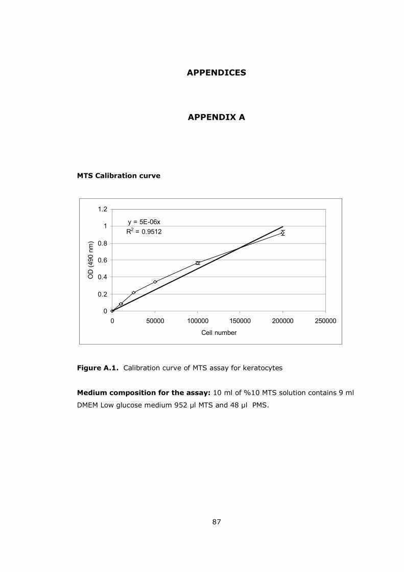
87
APPENDICES
APPENDIX A
MTS Calibration curve
y = 5E-06xR2 = 0.9512
0
0.2
0.4
0.6
0.8
1
1.2
0 50000 100000 150000 200000 250000
Cell number
OD
(490
nm
)
Figure A.1. Calibration curve of MTS assay for keratocytes
Medium composition for the assay: 10 ml of %10 MTS solution contains 9 ml
DMEM Low glucose medium 952 µl MTS and 48 µl PMS.