code guide 302 .pdf - plumbing & drainage institute
TRANSCRIPT

CODE GUIDE 302 and
Glossary of Industry Terms
A Guide for Code Authorities and Others for Selected Plumbing and Drainage
Products
Issued By THE PLUMBING AND DRAINAGE INSTITUTE
800 Turnpike Street ~ Suite 300 ~ North Andover, MA 01845
Phone: 800-589-8956
www.PDIonline.org ~ E-Mail: [email protected]
- %
PREFACE ADDENDUM:
The Plumbing and Drainage Institute is comprised of a group of member organizations, each of which is engaged in the manufacture of products for the plumbing industry. The basic aim of PDI is to contribute its combined talents and resources to the further advancement of plumbing engineering and the plumbing industry.
The Code Guide paragraphs in this booklet describe plumbing devices which are normally used in plumbing and drainage systems, and should be included when plumbing codes are written and adopted. The Plumbing and Drainage Institute has listed these paragraphs so that they include the following basic information, plus any additional information required for specific products:
1. Definition — A general description of the de-vice and its intended use.
2. Construction --- How the device should be constructed, and of what materials.
3. Where Required --- In what parts of the plumbing drainage system should this type of device be used.
4. Installation--- Recommendations regarding where and how the device should be installed.
5. Reference --- Where available, established Standards have been listed.
Recognizing that many terms used by the speci-fication Plumbing and Drainage Product Industry are unfamiliar to others, the Plumbing and Drainage Institute has expanded and revised this manual to include a comprehensive Glossary of Industry Terms. In this glossary, general as well as specific terms and definitions will be found in alphabetical order in each product category. Illustrations, where appropriate, have been in-cluded to clarify certain terms and identify pro-ducts and product components. Each illustra-tion has a figure number, and specific elements or components of products illustrated are iden-tified numerically where necessary for clarifica-tion. Even though certain terms apply to more than one product, numerical identification has been limited, in most cases, to one reference.
The Institute believes the glossary, which begins on Page 9, will provide answers to many questions and serve as a dependable reference for anyone interested in plumbing.
CONTENTS
Copyright 1983 Revised 2008
Plumbing and Drainage Institute
Page
Air Gap Fittings-Fixed ..................................................................... 1
Backwater Valves ................................................................................... 1
Cleanouts . ............................................................................................. 1 -2
Fixture Supports ................................................................................ 2-3
Floor Drains ............................................................................................ 3
Hydrants ................................................................................................. 3-4
Interceptors Grease… ..................................................................................... 4-5 Oil … ......................................................................................... 5 Sediment (Solids) .................................................................... 5-6
Roof Drains General .................................................................................... 6
Controlled Flow ........................................................................ 6-7
Sleeves--Waterproof .............................................................................. 7 Trap Primers--Automatic ........................................................................ 7-8 Water Hammer Arresters ....................................................................... 8
Glossary of Terms .................................................................................. 9-21
- 1 -
Air Gap Fittings-Fixed
Definition: A fixed air gap fitting is a device designed to
provide a rigid connection between indirect waste and the building drainage system, having an air gap of at least twice the effective diameter of the drain served to provide free circulation of air and prevent contamination from back siphonage or back flow.
Construction: Fixed air gap fittings shall be made of durable
corrosion resistant materials.
Where Required: All appliances, plumbing fixtures, sterilizers, stills,
equipment requiring cooling water, and other apparatus as designated by the Administrative Authority as having indirect waste connections, shall be provided with a fixed air gap fitting, as defined and described.
Installation: Fixed air gap fittings shall be installed in the ver-
tical position in the waste line on the inlet side of the trap.
Reference:
ANSI Standard A112.1, 2
(Backwater Valves)
Construction: Backwater valves shall be made of durable, cor-
rosion resistant materials. Valves must be con-structed as to insure a positive closing action against backflow. Valve access covers shall be bolted or threaded type and the access opening shall be large enough to permit removal of the internal parts.
Where Required: In any type of building where the plumbing
drainage system may be subject to backflow due to flooding of building sewers or storm sewers.
Installation: An approved backwater valve shall be installed
on the main horizontal building drain, downstream from any branch with openings that may be subjected to flooding, or an approved backwater valve shall be installed on each branch with openings that may be subjected to flooding. The backwater valve shall be located in the line where it shall be accessible for inspection and repair at all times.
Reference:
ANSI Standard ANSI-A112.14.1
Backwater Valves
Definition: Backwater valves are devices installed in building
drainage systems to prevent backflow. Valves are designed, utilizing a swing check, in either normally open or normally closed position.
Cleanouts Definition:
A cleanout is a device designed to provide access to horizontal or vertical drainage lines for cleaning and inspection.
Construction:
Cleanouts shall be made of durable corrosion resistant materials conforming in thickness to that required for pipe and fittings of the same material.
- 2 -
(Cleanouts)
The design shall be such that the closure plug when properly secured will make a gas and watertight seal. Cleanouts designed for use on concealed piping shall terminate at finished wall or floor surface with removable access cover of adequate size to permit removal of plug. Access covers used in floors shall be of sufficient strength to sustain area traffic.
Where Required: In all sanitary, waste and storm drainage
systems.
Installation: Cleanouts shall be installed not more than 50 feet
apart in horizontal drainage lines of 4-inch nominal diameter or less and not more than 100 feet apart for larger pipes. At each change of direction which is greater than 45 degrees, and at the base of each vertical soil or waste stack or as determined by the Administrative Authority, an accessible cleanout shall be installed.
Reference:
ANSI Standard ANSI-A112.36.2
Fixture Supports (Carriers) Definition:
A device that can be normally concealed in the building construction, designed to support off-the-floor plumbing fixtures independent of the wall or partition.
Construction: Fixture supports (carriers) shall be designed and
constructed to meet the following requirements. All items are to be of the material specified suitable for installation and service in the place specified. The castings for all components shall be sound, free of blow holes, cold shuts and other imperfections, and shall be of uniform wall thickness and true to pattern. They shall also be clean and free of fins.
(Fixture Supports)
1. Water Closets-Supports for off-the-floor closets shall be a combination waste fitting and support assembly and incorporate as a minimum a support structure complete with fasteners to mount and connect the closet, fitting and conduit means for carrying the waste from the closet into the waste line, means to tie the assembly to the structural floor slab, any necessary gasketing, and the combination shall provide an assembly that will support the fixture independent of the wall or partition and that can be fully concealed in the building construction.
2. Urinals-Supports for off-the-floor mens’ urinals shall be of the chair carrier type. The carrier shall provide the necessary means for mounting the fixture, a foot or feet to anchor the assembly to the floor slab, adjustability to locate the fixture at the desired height and in relation to the wall, and be designed to rigidly support the fixture under normal usage without damaging stress on the wall structure or wall finish.
3. Lavatories-Supports for off-the-floor lavatories and fixtures similar in size, design, and use shall be of the chair carrier type. The carrier shall provide the necessary means for mounting the fixture, a foot or feet to anchor the assembly to the floor slab, adjustability to locate the fixture at the desired height and in relation to the wall, and be designed to rigidly support the fixture under normal usage without damaging stress on the wall structure or wall finish.
4. Sinks-Supports for sinks and similar fixtures larger in size than conventional lavatories shall be of the chair carrier type. The carrier shall provide the necessary means to mount the fixture, feet to anchor the assembly to the floor slab, adjustability to locate the fixture at the desired height and in relation to the wall.
Where Required:
In all public buildings off-the-floor fixtures must be supported by devices described herein.
- 3 -
(Fixture Supports)
Installation: Fixture supports shall be installed in accordance
with manufacturer’s instructions.
Reference:
ANSI Standard ANSI-A112.6.1 M
Floor Drains Definition:
A manufactured receptacle designed to receive and convey run-off water or other liquid from building floors to the drainage system.
Construction: Floor drains shall be constructed of cast iron,
bronze or other durable corrosion resistant materials.
All internal surfaces shall be sloped to outlet to facilitate drainage.
Floor drains installed in rooms which are required to have waterproof floors shall have an integral flange, seepage openings and clamping device which will securely clamp the waterproof membrane. Each floor drain grate must be load rated to safely bear the maximum anticipated load which will pass over it.
Floor drains which receive debris laden waste water shall have a suitable sediment bucket in the drain body, which will intercept and retain this debris.
Where Required: All areas which are subject to water spillage,
overflow of washing equipment or cleaning water shall have an approved floor drain installed.
Every public restroom shall have not less than one (1) approved floor drain connected to the sanitary system. One floor drain shall be installed for each 400 sq. ft. of floor area or major fraction thereof.
(Floor Drains)
Food Handling Areas:
All areas where food is either handled or processed shall have sanitary types of floor drains installed. Sanitary floor drains must have an acid resistant porcelain enamel interior, (or equivalent, as approved by the Administrative Authority), and either a bronze or nickel bronze top rim and grate. Food scraps, peelings and miscellaneous kitchen debris shall be intercepted by a sediment bucket inserted in drain body. Sediment bucket must be easily removable to permit frequent cleaning.
Installation: Floor drains must be installed at the low points of
the areas to be drained, with tops of drains set flush with finished floor. Drains must be easily accessible for maintenance.
Reference:
ANSI Standard ANSI-A112.21.1M
Hydrants
Definition:
A hydrant is a device to provide a water supply with a shut-off valve and with a means to connect a hose in a safe and sanitary manner.
Construction: Hydrants shall be designed to pass through walls
or extend out of the ground and may terminate flush with or extend beyond the respective surfaces. All hydrants terminating in areas subject to freezing temperatures shall be designed to operate in these temperatures. Hydrants shall be designed so the seats, seat washers and other parts subject to wear can be replaced from the face of the hydrant without removing the hydrant from its installed position. Hydrants shall be constructed of durable corrosion-resistant materials and shall be key operated. Hydrants shall be equipped with an approved vacuum breaker when required by the Administrative Authority.
- 4 -
(Hydrants)
Where Required: All public and commercial buildings and grounds
where water outlets are required shall be equipped with approved hydrants as described herein.
Installation: Wall hydrants shall be installed with valves
exposed in heated area of buildings, and ground or post type hydrants shall be installed with valves below frost line to prevent freezing. Hydrants shall be installed and spaced as required for practical use.
Reference:
ANSI Standard ANSI A112.21.3 ANSI/ASSE Standard No. 1019
Hydro Mechanical Grease
Interceptors-
Definition:
A Hydro mechanical grease interceptor is a device to separate and retain light density liquids, (grease, fats, cooking oils, etc.), for easy removal.
Construction: Grease interceptors shall be made of durable
corrosion resistant materials. They shall have a double wall trap partition, and a gas and water tight cover securely fastened in place with easy means of manual or automatic removal of grease.
Where Required: All institutions or commercial establishments in
which grease, fats or oils are waste products of food cookery or processing, or in which grease, fats or oils are wasted, in connection with utensils, vat, dish or floor cleaning processes, that may be detrimental to the building drainage system, the public or private sewer or sewage treatment plant and any receiving watercourse, shall install grease interceptors of approved type. Typical applications are restaurants -- pot and pan sinks, dishwashers, animal slaughtering houses -- meat processing plants.
(Interceptors-Grease)
Installation: Where practical and feasible, one interceptor
shall be provided for each fixture or unit of equipment that discharges grease, fat and/or emulsified grease laden waste. However, two or more fixtures or units may be grouped on a single interceptor, subject to proper sizing of the interceptor and proper installation of flow control as stated herein. The interceptor shall, in all instances, be installed as close as possible to the fixture or unit served.
Flow Control: A device which controls the rate of flow through
an interceptor shall be installed at the fixture so as
to be readily accessible for inspection, service or
cleaning. It shall be installed in accordance with
the manufacturer’s recommendation. On multiple
discharges to a common interceptor, a flow control
shall be installed in the waste branch leading from
each fixture and be so rated that the combined
flow from all discharges will not develop sufficient
head so that the established flow rate of the
interceptor can be exceeded. When waste from
two or more fixtures, located close together, is
combined to be served by one interceptor, a single
flow control fitting should be used.
Servicing:
Grease interceptors shall be of the type that can be cleaned of grease in a short period of time. In-terceptors shall be easily accessible for cleaning and the accumulated materials shall be removed at such intervals as may be necessary to insure their exclusion from the sewage system.
Prohibited Types and Locations:
Grease interceptor shall not be installed where surrounding temperatures under operating conditions are less than 40°F. Grease interceptor shall not receive the discharge from a food waste grinder.
Capacity:
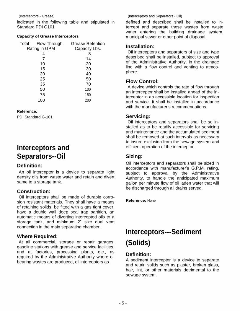
Grease interceptors shall have the grease reten-tion capacity for the specified flow through rate as
- 5 -
(Interceptors - Grease)
indicated in the following table and stipulated in
Standard PDI G101
Capacity of Grease Interceptors
Total Flow-Through Rating in GPM
Grease Retention Capacity Lbs.
4 8
7 14 10 20 15 30 20 40
25 50
35 70
50 100
75 150
100 200
Reference:
PDI Standard G-101
Interceptors and Separators--Oil Definition:
An oil interceptor is a device to separate light density oils from waste water and retain and divert same to a storage tank.
Construction: Oil interceptors shall be made of durable corro-
sion resistant materials. They shall have a means of retaining solids, be fitted with a gas tight cover, have a double wall deep seal trap partition, an automatic means of diverting intercepted oils to a storage tank, and minimum 2” size dual vent connection in the main separating chamber.
Where Required: At all commercial, storage or repair garages,
gasoline stations with grease and service facilities, and at factories, processing plants, etc., as required by the Administrative Authority where oil bearing wastes are produced, oil interceptors as
(Interceptors and Separators - Oil)
defined and described shall be installed to in-tercept and separate these wastes from waste water entering the building drainage system, municipal sewer or other point of disposal.
Installation: Oil interceptors and separators of size and type
described shall be installed, subject to approval of the Administrative Authority, in the drainage line with a flow control and venting to atmos-phere.
Flow Control: A device which controls the rate of flow through
an interceptor shall be installed ahead of the in-terceptor in an accessible location for inspection and service. It shall be installed in accordance with the manufacturer’s recommendations.
Servicing: Oil interceptors and separators shall be so in-
stalled as to be readily accessible for servicing and maintenance and the accumulated sediment shall be removed at such intervals as necessary to insure exclusion from the sewage system and efficient operation of the interceptor.
Sizing:
Oil interceptors and separators shall be sized in accordance with manufacturer’s G.P.M. rating, subject to approval by the Administrative Authority, to handle the anticipated maximum gallon per minute flow of oil laden water that will be discharged through all drains served.
Reference: None
Interceptors---Sediment
(Solids)
Definition: A sediment interceptor is a device to separate and retain solids such as plaster, broken glass, hair, lint, or other materials detrimental to the sewage system.
- 6 -
(Interceptors - Sediment/Solids)
Construction: Sediment interceptors shall be made of durable corrosion-resistant materials, and shall be equipped with a basket, screens or similar inter-cepting device which is removable for cleaning.
Where Required:
All bottling establishments, slaughter houses, barber shops, laboratories and other similar lo-cations as required by the Administrative Authority where wastes bearing plaster, hair, lint, entrails, broken glass, strings or other solids are produced, shall install sediment interceptors as defined and described to separate solids from waste water entering the building drainage system, municipal sewer or other point of disposal.
Installation:
Sediment interceptors shall be installed where required, and located, accessible for easy clean-ing, subject to approval of the Administrative Authority. On lavatories and sinks the sediment interceptor shall provide a trap seal within the body to serve as the fixture trap.
Reference: None
(Roof Drains)
the roof drain is connected. Roof drains installed in special areas such as parapets, gutters, cornices and decks shall be the type designed for the specific purpose. Deck roof drains with flat strainers shall have available inlet area not less than two times the area of the leader or conductor to which the deck roof drain is connected.
Installation-General Purpose:
Roof drains shall be located and sized on the basis of actual maximum projected roof areas and a fixed allowable area for each size vertical conductor or leader and each size horizontal building storm drain based on local rainfall intensities.
Where Required:
On all roof areas of commercial buildings exclusive of those specifically designed for gutters and exterior down spouts.
Reference:
ANSI Standard ANSI A112.21.2
Roof Drains General Purpose, Parapet, Gutter, Cornice, Deck and Control Flow
Definition: A roof drain is a receptacle designed to receive
and convey rain water from roof areas to the drainage system.
Construction:
Roof drains shall be constructed of cast iron, brass or other durable corrosion resisting material. General purpose roof drains shall consist of drain body sump, combination flashing ring and gravel stop and dome extending not less than 4” above the surface of the roof immediately adjacent and shall have available inlet area not less than 1 ½ times the area of the leader or conductor to which
Controlled Flow Roof Drain Systems Application: In lieu of sizing the roof storm drainage system on
the basis of actual maximum projected roof areas as previously described, the roof drainage system, or part thereof, may be sized on adjusted maximum flow rates which result from controlled flow and temporary retention of storm water on the roof, provided control devices approved by Administrative Authority are used and the roof design conforms to the requirements provided below. Controlled flow drains may be used on dead flat roofs or sloping roofs where slopes are small in the order of ⅛” to ¼” per foot.
- 7 -
(Controlled Flow Roof Drain Systems)
Design Limitations:
All control flow devices shall be mathematically related to the U.S. Weather Bureau Rainfall Intensity-Duration-Frequency data so that water depths on the roof, flow rates through the drains, and drain-down times can be accurately predicted for any desired design limitations. Vertical leaders and horizontal drains shall be sized in accordance with local codes to handle the maximum flow rate in G.P.M. obtainable through the control flow drains.
Roof Design:
Flashing should extend at least 3” above the maximum design water depth to accommodate any wind action and consequent waves. All roofs equipped with controlled flow drainage should be provided with adequate scuppers or other overflow means that will guarantee that the live load limitations of the roof are not exceeded.
Installation Control Flow Drain Systems: All control flow devices shall be protected by
strainers. The roof surface in the vicinity of the drain on dead flat roofs shall not be recessed to create a reservoir. On roofs with a slight slope the drains must be located in the valleys created by the slope but not in a depression created by other than a slight uniform slope.
Location:
Control flow drains should be located in accord-ance with manufacturer’s recommendations.
Reference: None
Sleeves -- Waterproof
Definition:
A waterproof sleeve is a device designed to pro-vide watertight means for passing pipes through floors, walls or roofs.
Construction: Waterproof sleeves shall be of cast iron, brass or
other durable corrosion resisting material. A recess or other means shall be provided to receive joint sealant material to waterproof area between pipe and sleeve. Sleeves shall have flashing flange and clamp device for securing to waterproof membrane where required.
Where Required: At any location where a pipe passes through a
wall, floor, or roof where a waterproof seal must be provided.
Installation: Waterproof sleeves shall be installed in floors,
walls or roofs where annular space between sleeves and pipe must be waterproof.
Reference: None
Trap Primers -- Automatic
Definition: An automatic trap primer is a device with an
integral air gap to divert a small portion of the cold water flowing to a frequently used fixture to a water sealed trap.
- 8 -
(Trap Primers-Automatic)
Construction: A trap primer shall be designed to install in a cold
water supply line to a lavatory or any other fre-quently used fixture. The trap primer will open in a positive manner thus diverting a small flow of water to the trap. The branch leading to the trap must be provided with strategically located air gap to prevent back-siphonage of waste water into the supply line. Pressure drop of the normal flow through the trap primer shall be held to a minimum. The trap primer should be serviceable without removing it from the line.
Where Required: All drains with wet trap seals and subject to infre-
quent use shall be guarded with automatic trap primers to prevent the unsanitary conditions created when sewer gases and bacteria escape after traps dry out due to evaporation.
Installation:
Installation shall be in accordance with man-ufacturers recommendations.
Reference:
* ASSE Standard No. 1018 *American Society of Sanitary Engineering
(Water Hammer Arrestors)
Construction: A water hammer arrester shall be constructed of
durable corrosion resistant material that will enable the unit to provide dependable service.
Where Required: All building water distribution systems shall have
approved engineered mechanical water hammer arresters installed on the hot and cold lines to reduce shock pressure to a degree that no hazard to the piping system will exist and no objectionable noise will be created.
Installation: Approved engineered mechanical water hammer
arresters must be installed in accordance with the Plumbing and Drainage Institute Water Hammer Arrester Standard PDI-WH 201 and/or American Society of Sanitary Engineering Water Hammer Arresters Standard No. 1010 or the USASI* (United States of America Standards Institute) No. A112.26.1
Reference:
PDI WH-201
*ASSE #l010 ANSI Standard-ANSI-A-112.26.1 *American Society of Sanitary Engineering
Water Hammer Arresters-Engineered Mechanical Type
Definition: An engineered mechanical water hammer
arrester is a device designed to provide continuous protection in water distribution systems against excessive surge pressure.
- 9 -
Glossary of Terms GENERAL TERMS
Terms listed in this category are trade terms and terms applicable to more than one product group as well as miscellaneous products. For specific terms and single product oriented general terms, refer to respective product sections.
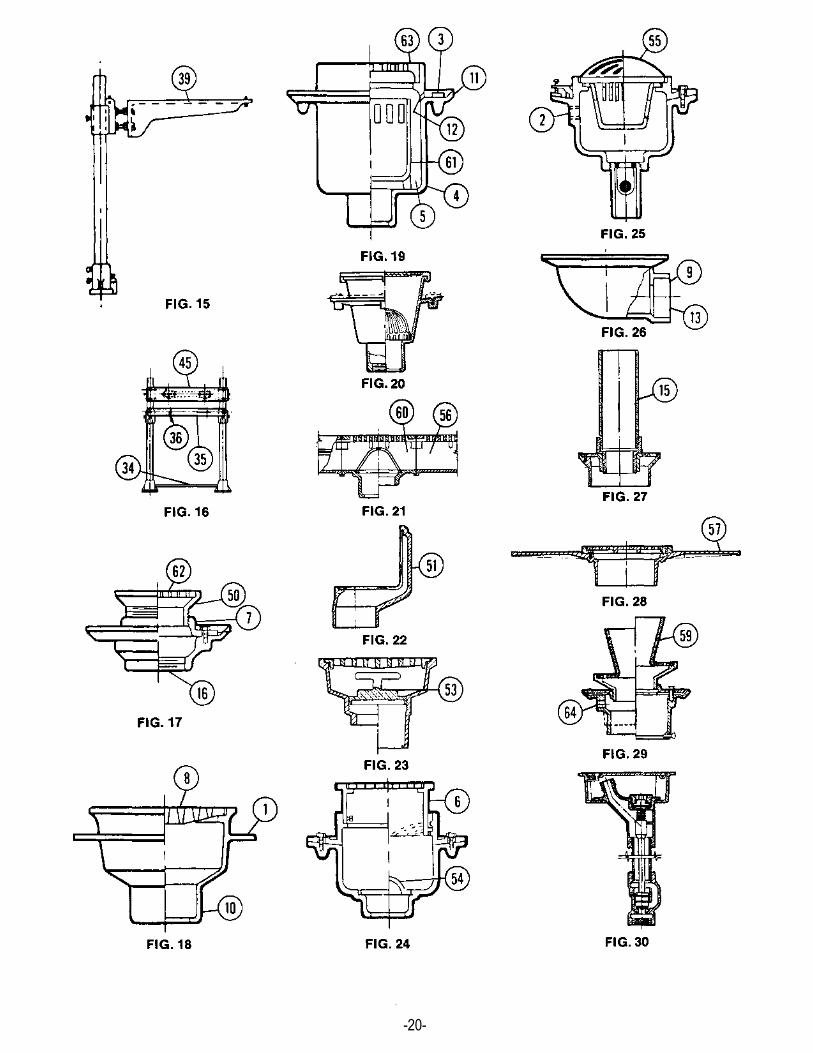
NOTE: The circled number indicates item defined. Illustrations begin on page 19.
Anchor Flange, Fig. 18
Flange extending from side of drain body which an-chors it in floor slab.
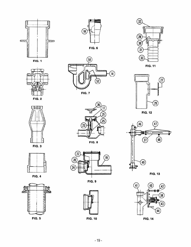
Anchor Sleeve, Fig. 1
A fitting with connections at both ends and anchor flange to attach and anchor piping passing through wall construction. Also referred to as wall sleeve.
Automatic Trap Primer, Fig. 2
A device with an integral air gap, installed in a cold water supply line of a frequently used fixture, diverting a small amount of water to a trap for the purpose of maintaining its seal.
Auxiliary Inlet, Fig. 25
Connection on side of body or fitting which receives discharge from another fixture or drain.
Bottom Outlet
Drain line connection to bottom of drain body.
Clamping Device, Fig. 19
Used to secure waterproofing membrane to seepage flange of body.
Drain Body, Fig. 19
Main part of drain which is connected to drain line and supports grate, adjustable strainer and/or other com-ponents of drain.
Body Sump, Fig. 19 Central portion of drain body immediately above or adjacent to the outlet.
Drain Outlet Gasket
An elastomeric compression sleeve used in place of lead and oakum to connect inside caulk outlet drains to the drainage piping system.
Drain Tile Sump
A form of junction box to which foundation drain tile is connected, with outlet connection to the building drain line. Normally used in conjunction with a floor level cleanout or drain, trap and backwater valve, or the combination of these components. Also referred to as tile connector drain or foundation drain.
Extension Collar, Fig. 24
Used to raise drain top to surface level to meet slab thickness and roughing requirements. Either fixed or adjustable.
Finished Floor
Floors which are covered with an additional "topping" over slab, such as floor tile or terrazzo for aesthetic purposes.
Fixed Air Gap Fitting, Fig. 3
A device designed to provide a rigid connection between indirect waste and the building drainage system, having an air gap of at least twice the effective diameter of the drain served to provide free circulation of air and prevent contamination from back siphonage or back flow.
Flashing Collar, Fig. 17
See CLAMPING DEVICE
Flat Grate, Fig. 18
Perforated, slotted, or otherwise opened flat top member of a drain which provides for drainage of liquids while restricting flow of solids and supports traffic within design limitations.
Fresh Air Inlet Cover
A protective cover which is installed on the outside building wall over the open entrance of fresh air inlet pipe with openings to permit free introduction of air to the building drainage system and prevent intake of solids that could block the entrance.
Hub Adapter
A fitting, threaded at one end with standard soil pipe hub at the other end which is used to convert threaded products to hub connections.
1
2
3
4
5
6
7
8
- 10 -
Hub Outlet, Fig. 26
A drain connection, usually on side outlet drains, which is reverse of inside caulk outlet where plain end of drain pipe is inserted and seal is made either by caulking or with compression gasket.
Inside Caulk Outlet, Fig. 18
Open bottom cup type drain connection which is placed over plain end of drain pipe in which the seal is made either by caulking or with compression gasket.
Laminated Top
Type of grate or cover where a non-ferrous top is attached to iron base for appearance and strength.
Outside Caulk (Hub) Outlet
See HUB OUTLET
Primer Adapter, Fig. 4
A fitting with auxiliary tapped inlet connection to attach trap primer feed line, which is connected to a floor drain outlet ahead of the trap. Also referred to as auxiliary inlet fitting.
Seepage Flange, Fig. 19
Flange extending from side of drain body below seep- age openings to collect seepage that may occur around drain and direct same into the seepage openings, thus preventing such seepage from bypassing drain.
Seepage Opening, Fig. 19
A perforation in side wall of drain body sump, usually several are included, above seepage flange to receive any seepage from around drain and direct same into the sump.
Side Outlet, Fig. 26
Lateral drain line connection at side of drain body.
Spigot Adapter
A fitting, threaded at one end with standard soil pipe spigot at the other end which is used to convert threaded spigot connections.
Spigot Outlet, Fig. 7
Male, pipe size, plain end connection for caulking into soil pipe hub or joining to plain end pipe with mechanical coupling—i.e., NO-HUB.
Standpipe, Fig. 27
A removable pipe used in connection with closed top drain to maintain a specified water level above drain top in
pools and the like.
Threaded (Tapped) Outlet, Fig. 17
Internally threaded drain line connection for joining drain to threaded pipe drain line with American Standard Taper pipe threads (NPT).
Unfinished Floor
Floor where top of slab serves as final traffic surface and no additional flooring or topping is applied.
Vandalproof
Used to define securing of grates and other exposed removable parts to discourage unauthorized removal.
Vandalproof Vent Cap
A protective cover which is installed on top of vent stacks terminating above roof level, with openings to permit free circulation of air and prevent insertion of objects that could block the vent system, designed and secured in a manner to discourage vandalism.
Veneered Top
See LAMINATED TOP.
Waterproof Sleeve, Fig. 5
A fitting normally with anchor flange, flashing clamp device and hub-like caulking recess at the top for installation in floor slabs as a sleeve through which piping is passed and caulked in place to prevent leakage.
Weep Hole, Fig. 19 See SEEPAGE OPENING.
Wide Flange, Fig. 28
A flange surrounding and slightly below the top rim on certain drains and cleanouts and adjustable strainers to which composition deck material is bonded.
BACKWATER VALVES
DEFINITION
A device installed in a drain line which prevents backflow without obstructing normal flow.
TYPES
Ball Float Check Valve, Fig. 6
A backwater valve for vertical installation at outlet of floor drain.
9
1008
11
12
13
14
15
16
12
57
- 11 -
Combination Floor Drain and Backwater Valve, Fig. 7
A floor drain incorporating an internal swing check or ball float valve to prevent backflow.
Combination Horizontal Backwater Valve and Manual Gate Valve, Fig. 8
A backwater valve for installation in a horizontal drain line incorporating an internal swing check valve and manual gate valve to prevent backflow.
Horizontal Backwater Valve, Fig. 9
A backwater valve for installation in a horizontal drain line incorporating an internal swing check valve to prevent backflow.
Terminal Backwater Valve, Fig. 10
A backwater valve for installation at the discharge end of a horizontal drain line incorporating a swing check valve to prevent backflow.
SPECIFIC TERMS
Access Cover, Fig. 8 Removable cover, usually at floor level, which permits access to working parts of the valve.
Ball Float, Fig. 6
Buoyant sealing element of valve which seals drain against backflow upon internal water level increase.
Body, Fig. 9
Housing portion of valve which contains all working parts.
Flapper, Fig. 9
See ROTATING DISC.
Gland Plate (Gasketed), Fig. 8
Component of manual gate valve which supports all working parts.
Hinge Arm, Fig. 9
Component of swing check valve which supports rotating disc.
Non-Rising Stem, Fig. 8
Component of manual gate valve which supports shear gate and provides vertical adjustment of same.
Rotating Disc, Fig. 9 Component of swing check valve supported by hinge arm which closes upon backflow and rotates to dislodge debris from seat.
Seat, Fig. 9
Fixed component of backwater valve which completes seal when mated with rotating disc, shear gate, or ball float.
Shear Gate, Fig. 8
Manually controlled element of gate valve which seals against backflow and is spade-shaped to cut through debris in line upon closure.
Spade Gate, Fig. 8
See SHEAR GATE
Wheel Handle, Fig. 8
Removable component of manual gate valve through which valve is controlled.
CLEANOUTS
TYPES
Floor Cleanout, Fig. 11
A device designed to provide access through the floor or slab to horizontal lines for cleaning and inspection.
Wall Cleanout, Fig. 12
A device designed to provide access through the wall to drainage lines for cleaning and inspection.
SPECIFIC TERMS
Access Cover, Fig. 12
Plate which covers opening in floor or wall which leads to closure plug.
Adjustable Top Assembly, Fig. 11
Used in conjunction with a cleanout ferrule, which adjusts to meet finished floor level.
Cleanout Tee, Fig. 12
Tee fitting, installed in vertical or horizontal lines, with a suitable closure plug in run of tee to permit access to said lines.
Closure Plug, Fig. 11
Plug installed in ferrule to effect a water- and gas-tight seal—when removed, permits access to sewer line for cleaning or inspection. Seal may be NPT thread or NPSL with gasket.
17
18
19
20
21
22
23
20
24
25
25
26
27
28
29
30
18
- 12 -
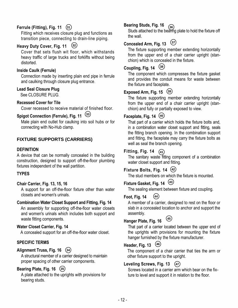
Ferrule (Fitting), Fig. 11
Fitting which receives closure plug and functions as transition piece, connecting to drain-line piping.
Heavy Duty Cover, Fig. 11
Cover that sets flush wit floor, which withstands heavy traffic of large trucks and forklifts without being distorted.
Inside Caulk (Ferrule)
Connection made by inserting plain end pipe in ferrule and caulking through closure plug entrance.
Lead Seal Closure Plug
See CLOSURE PLUG.
Recessed Cover for Tile
Cover recessed to receive material of finished floor.
Spigot Connection (Ferrule), Fig. 11
Male plain end outlet for caulking into soil hubs or for connecting with No-Hub clamp.
FIXTURE SUPPORTS (CARRIERS)
DEFINITION
A device that can be normally concealed in the building construction, designed to support off-the-floor plumbing fixtures independent of the wall partition.
TYPES
Chair Carrier, Fig. 13, 15, 16
A support for an off-the-floor fixture other than water closets and women's urinals.
Combination Water Closet Support and Fitting, Fig. 14
An assembly for supporting off-the-floor water closets and women's urinals which includes both support and waste fitting components.
Water Closet Carrier, Fig. 14
A concealed support for an off-the-floor water closet.
SPECIFIC TERMS
Alignment Truss, Fig. 16
A structural member of a carrier designed to maintain proper spacing of other carrier components.
Bearing Plate, Fig. 16
A plate attached to the uprights with provisions for bearing studs.
Bearing Studs, Fig. 16
Studs attached to the bearing plate to hold the fixture off the wall.
Concealed Arm, Fig. 13
The fixture supporting member extending horizontally from the upper end of a chair carrier upright (stan-chion) which is concealed in the fixture.
Coupling, Fig. 14
The component which compresses the fixture gasket and provides the conduit means for waste between the fixture and faceplate.
Exposed Arm, Fig. 15
The fixture supporting member extending horizontally from the upper end of a chair carrier upright (stan-chion) and fully or partially exposed to view.
Faceplate, Fig. 14
That part of a carrier which holds the fixture bolts and, in a combination water closet support and fitting, seals the fitting branch opening. In the combination support and fitting, the faceplate may carry the fixture bolts as well as seal the branch opening.
Fitting, Fig. 14
The sanitary waste fitting component of a combination water closet support and fitting.
Fixture Bolts, Fig. 14
The stud members on which the fixture is mounted.
Fixture Gasket, Fig. 14
The sealing element between fixture and coupling.
Foot, Fig. 14
A member of a carrier, designed to rest on the floor or slab in a concealed location to anchor and support the assembly.
Hanger Plate, Fig. 16
That part of a carrier located between the upper end of the uprights with provisions for mounting the fixture hanger furnished by the fixture manufacturer.
Header, Fig. 13
The component of a chair carrier that ties the arm or other fixture support to the upright.
Leveling Screws, Fig. 13
Screws located in a carrier arm which bear on the fix-ture to level and support it in relation to the floor.
31
40 33
34
35
36
37
38
39
32
41
42
43
44
45
46
47
38
- 13 -
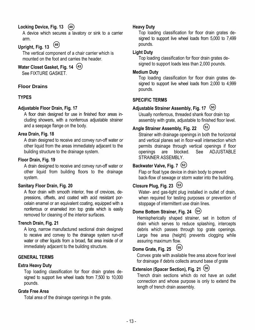
Locking Device, Fig. 13
A device which secures a lavatory or sink to a carrier arm.
Upright, Fig. 13
The vertical component of a chair carrier which is mounted on the foot and carries the header.
Water Closet Gasket, Fig. 14
See FIXTURE GASKET.
Floor Drains
TYPES
Adjustable Floor Drain, Fig. 17
A floor drain designed for use in finished floor areas in-cluding showers, with a nonferrous adjustable strainer and a seepage flange on the body.
Area Drain, Fig. 18
A drain designed to receive and convey run-off water or other liquid from the areas immediately adjacent to the building structure to the drainage system.
Floor Drain, Fig. 19
A drain designed to receive and convey run-off water or other liquid from building floors to the drainage system.
Sanitary Floor Drain, Fig. 20
A floor drain with smooth interior, free of crevices, de-pressions, offsets, and coated with acid resistant por-celain enamel or an equivalent coating, equipped with a nonferrous or enameled iron top grate which is easily removed for cleaning of the interior surfaces.
Trench Drain, Fig. 21
A long, narrow manufactured sectional drain designed to receive and convey to the drainage system run-off water or other liquids from a broad, flat area inside of or immediately adjacent to the building structure.
GENERAL TERMS
Extra Heavy Duty
Top loading classification for floor drain grates de-signed to support live wheel loads from 7,500 to 10,000 pounds.
Grate Free Area
Total area of the drainage openings in the grate.
Heavy Duty Top loading classification for floor drain grates de-signed to support live wheel loads from 5,000 to 7,499 pounds.
Light Duty Top loading classification for floor drain grates de-signed to support loads less than 2,000 pounds.
Medium Duty Top loading classification for floor drain grates de-signed to support live wheel loads from 2,000 to 4,999 pounds.
SPECIFIC TERMS
Adjustable Strainer Assembly, Fig. 17
Usually nonferrous, threaded shank floor drain top assembly with grate, adjustable to finished floor level.
Angle Strainer Assembly, Fig. 22
Strainer with drainage openings in both the horizontal and vertical planes set in floor-wall intersection which permits drainage through vertical openings if floor openings are blocked. See ADJUSTABLE STRAINER ASSEMBLY.
Backwater Valve, Fig. 7
Flap or float type device in drain body to prevent back-flow of sewage or storm water into the building.
Closure Plug, Fig. 23
Water- and gas-tight plug installed in outlet of drain, when required for testing purposes or prevention of stoppage of intermittent use drain lines.
Dome Bottom Strainer, Fig. 24
Hemispherically shaped strainer, set in bottom of drain which serves to reduce splashing, intercepts debris which passes through top grate openings. Large free area (height) prevents clogging while assuring maximum flow.
Dome Grate, Fig. 25
Convex grate with available free area above floor level for drainage if debris collects around base of grate
Extension (Spacer Section), Fig. 21
Trench drain sections which do not have an outlet connection and whose purpose is only to extend the length of trench drain assembly.
48
49
43
50
51
52
53
54
55
56
- 14 -
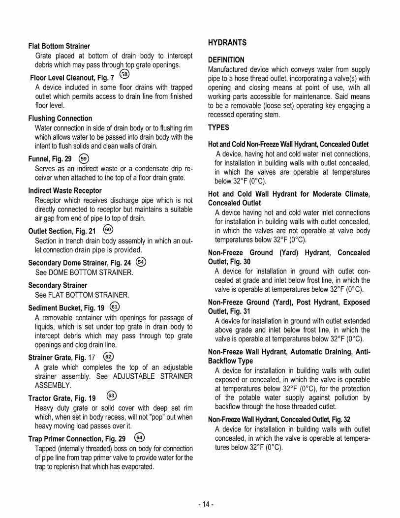
Flat Bottom Strainer
Grate placed at bottom of drain body to intercept debris which may pass through top grate openings.
Floor Level Cleanout, Fig. 7
A device included in some floor drains with trapped outlet which permits access to drain line from finished floor level.
Flushing Connection
Water connection in side of drain body or to flushing rim which allows water to be passed into drain body with the intent to flush solids and clean walls of drain.
Funnel, Fig. 29
Serves as an indirect waste or a condensate drip re-ceiver when attached to the top of a floor drain grate.
Indirect Waste Receptor
Receptor which receives discharge pipe which is not directly connected to receptor but maintains a suitable air gap from end of pipe to top of drain.
Outlet Section, Fig. 21
Section in trench drain body assembly in which an out-let connection drain pipe is provided.
Secondary Dome Strainer, Fig. 24
See DOME BOTTOM STRAINER.
Secondary Strainer
See FLAT BOTTOM STRAINER.
Sediment Bucket, Fig. 19
A removable container with openings for passage of liquids, which is set under top grate in drain body to intercept debris which may pass through top grate openings and clog drain line.
Strainer Grate, Fig. 17
A grate which completes the top of an adjustable strainer assembly. See ADJUSTABLE STRAINER ASSEMBLY.
Tractor Grate, Fig. 19
Heavy duty grate or solid cover with deep set rim which, when set in body recess, will not "pop" out when heavy moving load passes over it.
Trap Primer Connection, Fig. 29
Tapped (internally threaded) boss on body for connection of pipe line from trap primer valve to provide water for the trap to replenish that which has evaporated.
HYDRANTS
DEFINITION
Manufactured device which conveys water from supply pipe to a hose thread outlet, incorporating a valve(s) with opening and closing means at point of use, with all working parts accessible for maintenance. Said means to be a removable (loose set) operating key engaging a recessed operating stem.
TYPES
Hot and Cold Non-Freeze Wall Hydrant, Concealed Outlet
A device, having hot and cold water inlet connections, for installation in building walls with outlet concealed, in which the valves are operable at temperatures below 32°F (0°C).
Hot and Cold Wall Hydrant for Moderate Climate, Concealed Outlet
A device having hot and cold water inlet connections for installation in building walls with outlet concealed, in which the valves are not operable at valve body temperatures below 32°F (0°C).
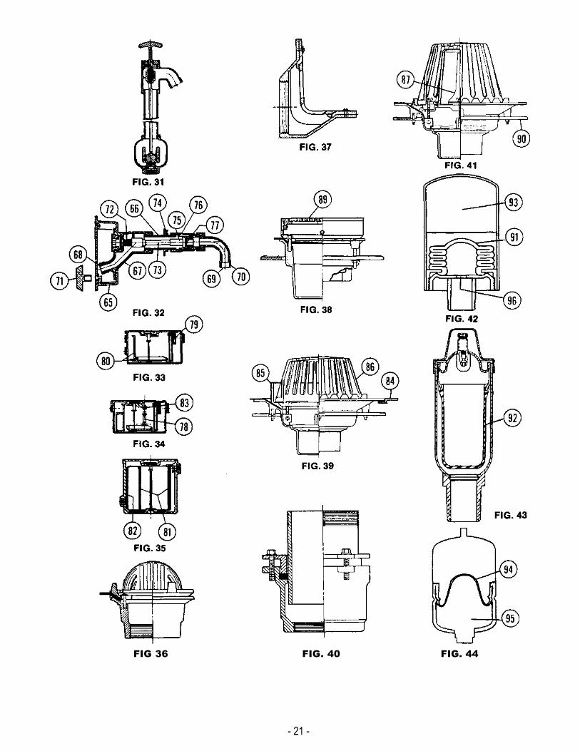
Non-Freeze Ground (Yard) Hydrant, Concealed Outlet, Fig. 30
A device for installation in ground with outlet con-cealed at grade and inlet below frost line, in which the valve is operable at temperatures below 32°F (0°C).
Non-Freeze Ground (Yard), Post Hydrant, Exposed Outlet, Fig. 31
A device for installation in ground with outlet extended above grade and inlet below frost line, in which the valve is operable at temperatures below 32°F (0°C).
Non-Freeze Wall Hydrant, Automatic Draining, Anti-Backflow Type
A device for installation in building walls with outlet exposed or concealed, in which the valve is operable at temperatures below 32°F (0°C), for the protection of the potable water supply against pollution by backflow through the hose threaded outlet.
Non-Freeze Wall Hydrant, Concealed Outlet, Fig. 32
A device for installation in building walls with outlet concealed, in which the valve is operable at tempera-tures below 32°F (0°C).
58
59
60
54
61
62
63
64
- 15 -
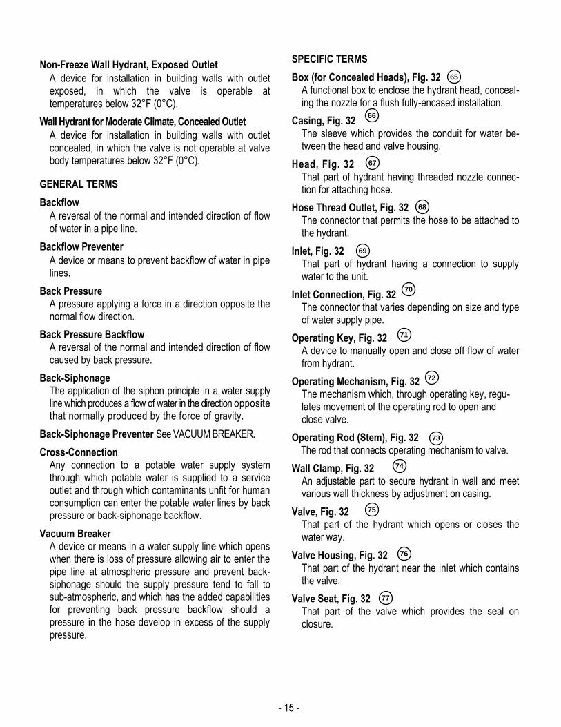
Non-Freeze Wall Hydrant, Exposed Outlet
A device for installation in building walls with outlet exposed, in which the valve is operable at temperatures below 32°F (0°C).
Wall Hydrant for Moderate Climate, Concealed Outlet
A device for installation in building walls with outlet concealed, in which the valve is not operable at valve body temperatures below 32°F (0°C).
GENERAL TERMS
Backflow
A reversal of the normal and intended direction of flow of water in a pipe line.
Backflow Preventer
A device or means to prevent backflow of water in pipe lines.
Back Pressure A pressure applying a force in a direction opposite the normal flow direction.
Back Pressure Backflow A reversal of the normal and intended direction of flow caused by back pressure.
Back-Siphonage The application of the siphon principle in a water supply line which produces a flow of water in the direction opposite that normally produced by the force of gravity.
Back-Siphonage Preventer See VACUUM BREAKER.
Cross-Connection Any connection to a potable water supply system through which potable water is supplied to a service outlet and through which contaminants unfit for human consumption can enter the potable water lines by back pressure or back-siphonage backflow.
Vacuum Breaker A device or means in a water supply line which opens when there is loss of pressure allowing air to enter the pipe line at atmospheric pressure and prevent back-siphonage should the supply pressure tend to fall to sub-atmospheric, and which has the added capabilities for preventing back pressure backflow should a pressure in the hose develop in excess of the supply pressure.
SPECIFIC TERMS
Box (for Concealed Heads), Fig. 32 A functional box to enclose the hydrant head, conceal-ing the nozzle for a flush fully-encased installation.
Casing, Fig. 32 The sleeve which provides the conduit for water be-tween the head and valve housing.
Head, Fig. 32 That part of hydrant having threaded nozzle connec-tion for attaching hose.
Hose Thread Outlet, Fig. 32 The connector that permits the hose to be attached to the hydrant.
Inlet, Fig. 32 That part of hydrant having a connection to supply water to the unit.
Inlet Connection, Fig. 32 The connector that varies depending on size and type of water supply pipe.
Operating Key, Fig. 32 A device to manually open and close off flow of water from hydrant.
Operating Mechanism, Fig. 32 The mechanism which, through operating key, regu-lates movement of the operating rod to open and close valve.
Operating Rod (Stem), Fig. 32 The rod that connects operating mechanism to valve.
Wall Clamp, Fig. 32 An adjustable part to secure hydrant in wall and meet various wall thickness by adjustment on casing.
Valve, Fig. 32 That part of the hydrant which opens or closes the water way.
Valve Housing, Fig. 32 That part of the hydrant near the inlet which contains the valve.
Valve Seat, Fig. 32 That part of the valve which provides the seal on closure.
65
66
67
68
69
70
71
72
73
74
75
764
77
- 16 -
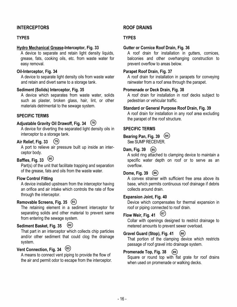
INTERCEPTORS
TYPES
Hydro Mechanical Grease-Interceptor, Fig. 33 A device to separate and retain light density liquids, grease, fats, cooking oils, etc. from waste water for easy removal.
Oil-Interceptor, Fig. 34 A device to separate light density oils from waste water and retain and divert same to a storage tank.
Sediment (Solids) Interceptor, Fig. 35 A device which separates from waste water, solids such as plaster, broken glass, hair, lint, or other materials detrimental to the sewage system.
SPECIFIC TERMS
Adjustable Gravity Oil Drawoff, Fig. 34 A device for diverting the separated light density oils in interceptor to a storage tank.
Air Relief, Fig. 33 A port to relieve air pressure built up inside an inter-ceptor body.
Baffles, Fig. 33 Part(s) of the unit that facilitate trapping and separation of the grease, fats and oils from the waste water.
Flow Control Fitting A device installed upstream from the interceptor having an orifice and air intake which controls the rate of flow through the interceptor.
Removable Screens, Fig. 35 The retaining element in a sediment interceptor for separating solids and other material to prevent same from entering the sewage system.
Sediment Basket, Fig. 35 That part in an interceptor which collects chip particles and/or other sediment that could clog the drainage system.
Vent Connection, Fig. 34 A means to connect vent piping to provide the flow of the air and permit odor to escape from the interceptor.
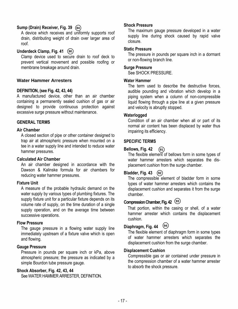
ROOF DRAINS
TYPES
Gutter or Cornice Roof Drain, Fig. 36 A roof drain for installation in gutters, cornices, balconies and other overhanging construction to prevent overflow to areas below.
Parapet Roof Drain, Fig. 37 A roof drain for installation in parapets for conveying rainwater from a roof area through the parapet.
Promenade or Deck Drain, Fig. 38 A roof drain for installation in roof decks subject to pedestrian or vehicular traffic.
Standard or General Purpose Roof Drain, Fig. 39 A roof drain for installation in any roof area excluding the parapet of the roof structure.
SPECIFIC TERMS
Bearing Pan, Fig. 39 See SUMP RECEIVER.
Dam, Fig. 39 A solid ring attached to clamping device to maintain a specific water depth on roof or to serve as an overflow.
Dome, Fig. 39 A convex strainer with sufficient free area above its base, which permits continuous roof drainage if debris collects around drain.
Expansion Joint, Fig. 40 Device which compensates for thermal expansion in roof or piping connected to roof drain.
Flow Weir, Fig. 41 Collar with openings designed to restrict drainage to metered amounts to prevent sewer overload.
Gravel Guard (Stop), Fig. 41 That portion of the clamping device which restricts passage of roof gravel into drainage system.
Promenade Top, Fig. 38 Square or round top with flat grate for roof drains when used on promenade or walking decks.
78
79
80
81
82
83
84
85
86
87
88
89
- 17 -
Sump (Drain) Receiver, Fig. 39 A device which receives and uniformly supports roof drain, distributing weight of drain over larger area of roof.
Underdeck Clamp, Fig. 41 Clamp device used to secure drain to roof deck to prevent vertical movement and possible roofing or membrane breakage around drain.
Water Hammer Arresters
DEFINITION, (see Fig. 42, 43, 44) A manufactured device, other than an air chamber containing a permanently sealed cushion of gas or air designed to provide continuous protection against excessive surge pressure without maintenance.
GENERAL TERMS
Air Chamber A closed section of pipe or other container designed to trap air at atmospheric pressure when mounted on a tee in a water supply line and intended to reduce water hammer pressures.
Calculated Air Chamber An air chamber designed in accordance with the Dawson & Kalinske formula for air chambers for reducing water hammer pressures.
Fixture Unit A measure of the probable hydraulic demand on the water supply by various types of plumbing fixtures. The supply fixture unit for a particular fixture depends on its volume rate of supply, on the time duration of a single supply operation, and on the average time between successive operations.
Flow Pressure The gauge pressure in a flowing water supply line immediately upstream of a fixture valve which is open and flowing.
Gauge Pressure Pressure in pounds per square inch or kPa, above atmospheric pressure; the pressure as indicated by a simple Bourdon tube pressure gauge.
Shock Absorber, Fig. 42, 43, 44 See WATER HAMMER ARRESTER, DEFINITION.
Shock Pressure The maximum gauge pressure developed in a water supply line during shock caused by rapid valve closure.
Static Pressure The pressure in pounds per square inch in a dormant or non-flowing branch line.
Surge Pressure See SHOCK PRESSURE.
Water Hammer The term used to describe the destructive forces, audible pounding and vibration which develop in a piping system when a column of non-compressible liquid flowing through a pipe line at a given pressure and velocity is abruptly stopped.
Waterlogged Condition of an air chamber when all or part of its normal air content has been displaced by water thus impairing its efficiency.
SPECIFIC TERMS
Bellows, Fig. 42 The flexible element of bellows form in some types of water hammer arresters which separates the dis-placement cushion from the surge chamber.
Bladder, Fig. 43 The compressible element of bladder form in some types of water hammer arresters which contains the displacement cushion and separates it from the surge chamber.
Compression Chamber, Fig. 42
That portion, within the casing or shell, of a water hammer arrester which contains the displacement cushion.
Diaphragm, Fig. 44 The flexible element of diaphragm form in some types of water hammer arresters which separates the displacement cushion from the surge chamber.
Displacement Cushion Compressible gas or air contained under pressure in the compression chamber of a water hammer arrester to absorb the shock pressure.
90
84
91
92
93
94
94
- 18 -
Displacement Fluid Used in some water hammer arresters as an interface between the displacement cushion and the flexible element.
Hydraulic Fluid See DISPLACEMENT FLUID.
Surge Chamber, Fig. 44 That portion within a water hammer arrester which is in direct fluid communication with the piping system which receives the fluid surge for suppression.
Surge Control Orifice, Fig. 42 A restricted opening at the inlet of some water hammer arresters provided to decrease the rate of pressure change of the liquid flowing between the surge chamber and the pipe system.
95
96
- 19 -
-20-
- 21 -
FIG 36 FIG. 40 FIG. 44

THE PLUMBING AND DRAINAGE INSTITUTE 800 Turnpike Street ~ Suite 300
North Andover, MA 01845 Phone: 1-800-589-8956
Web: www.PDIonline.org ~ E-Mail: [email protected]