underground drainage systems - marley plumbing and
TRANSCRIPT

Underground Drainage Systems
marleypd.co.uk

3MARLEY Underground Drainage Systems |
Marley Underground Drainage Systems
The Marley Plumbing & Drainage range of underground
systems include the solid wall range, predominately for
round the house drainage and Quantum structured wall
range for sewer and highway drainage applications.
Contents
4 Solid wall systems
5 Structured wall systems
6 Key components
8 Design
10 Installation data
24 British & European standards
25 Marley system solutions
26-43 Product range
Innovation & ExpertiseInnovation & Expertise
StandardsBritish StandardsA wide range of components featured in this price list conform to British Standard Specifications, many items bear the British Standards Institution’s Kite Mark symbol, , as indicated throughout this price list. The presence of this mark on, or in relation to, a product is an assurance that the goods have been produced under a system of supervision, control and testing, operated during manufacture and including periodical inspection of the manufacturer’s works in accordance with the Certification Mark Scheme.
Agrément CertificatesCertain components and systems illustrated in this price list have been independently assessed and are the subject of certification by the British Board of Agrément. These items are indicated by the BBA symbol, , throughout this price list.
Copies of Marley Plumbing & Drainage BBA Certificates are freely available from the Company upon request or from marleypd.co.uk.
Certificate No. 88/1977 94/2985 98/3486 09/H146 11/H172
KM 05495KM 05495KM542682
54 MARLEY Underground Drainage Systems || MARLEY Underground Drainage Systems All documentation can be downloaded from marleypd.co.uk Technical hotline: 01622 852695
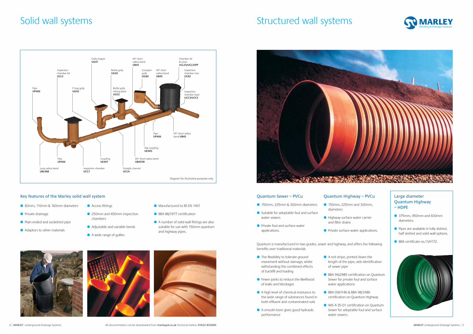
Solid wall systems
Key features of the Marley solid wall system
● 82mm, 110mm & 160mm diameters
● Private drainage
● Plain ended and socketted pipe
● Adaptors to other materials
● Access fittings
● 250mm and 450mm inspection chambers
● Adjustable and variable bends
● A wide range of gullies
● Manufactured to BS EN 1401
● BBA 88/1977 certification
● A number of solid wall fittings are also suitable for use with 150mm quantum and highway pipes.
PipeUP406
Gully hopper UG47
PipeUP406
PipeUP406
Slip couplingUE405
Inspection chamberUCC7
Inspection chamber baseUCC3/UCC5
Inspection chamber riser UCR2
Straight channelUCC4
CouplingUE407
45º short radius bend UB45
45º short radius bendUB455R
Long radius bendUBL488
Inspection chamber lid UCL3
P trap gully UG42
Bottle gully UG50
Bottle gully raising piece UG52
Compact gully UG40
45º short radius bendUB45
Chamber lid & cover UCL35/UCL35PP
45º short radius bendUB45
Diagram for illustrative purposes only
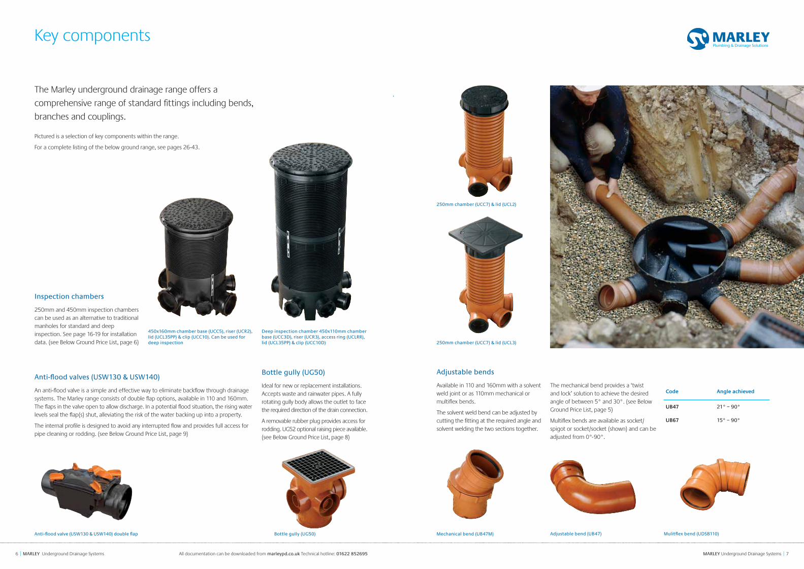
Structured wall systems
Quantum is manufactured in two grades, sewer and highway, and offers the following benefits over traditional materials
● The flexibility to tolerate ground movement without damage, whilst withstanding the combined effects of backfill and loading
● Fewer joints to reduce the likelihood of leaks and blockages
● A high level of chemical resistance to the wide range of substances found in both effluent and contaminated soils
● A smooth bore gives good hydraulic performance
● A red stripe, printed down the length of the pipe, aids identification of sewer pipe
● BBA 94/2985 certification on Quantum Sewer for private foul and surface water applications
● BBA 09/H146 & BBA 98/3486 certification on Quantum Highway
● WIS 4-35-01 certification on Quantum Sewer for adoptable foul and surface water sewers.
Quantum Sewer – PVCu
● 150mm, 225mm & 300mm diameters
● Suitable for adoptable foul and surface water sewers
● Private foul and surface water applications.
Quantum Highway – PVCu
● 150mm, 225mm and 300mm, diameters
● Highway surface water carrier and filter drains
● Private surface water applications.
Large diameter Quantum Highway – HDPE
● 375mm, 450mm and 600mm diameters.
● Pipes are available in fully slotted, half slotted and solid wall options.
● BBA certificate no.11/H172.
76 MARLEY Underground Drainage Systems || MARLEY Underground Drainage Systems All documentation can be downloaded from marleypd.co.uk Technical hotline: 01622 852695
Key components
The Marley underground drainage range offers a
comprehensive range of standard fittings including bends,
branches and couplings.
Pictured is a selection of key components within the range.
For a complete listing of the below ground range, see pages 26-43.
Anti-flood valves (USW130 & USW140)
An anti-flood valve is a simple and effective way to eliminate backflow through drainage systems. The Marley range consists of double flap options, available in 110 and 160mm. The flaps in the valve open to allow discharge. In a potential flood situation, the rising water levels seal the flap(s) shut, alleviating the risk of the water backing up into a property.
The internal profile is designed to avoid any interrupted flow and provides full access for pipe cleaning or rodding. (see Below Ground Price List, page 9)
Bottle gully (UG50)
Ideal for new or replacement installations. Accepts waste and rainwater pipes. A fully rotating gully body allows the outlet to face the required direction of the drain connection.
A removable rubber plug provides access for rodding. UG52 optional raising piece available. (see Below Ground Price List, page 8)
Adjustable bends
Available in 110 and 160mm with a solvent weld joint or as 110mm mechanical or multiflex bends.
The solvent weld bend can be adjusted by cutting the fitting at the required angle and solvent welding the two sections together.
The mechanical bend provides a ‘twist and lock’ solution to achieve the desired angle of between 5° and 30°. (see Below Ground Price List, page 5)
Multiflex bends are available as socket/spigot or socket/socket (shown) and can be adjusted from 0°-90°.
Inspection chambers
250mm and 450mm inspection chambers can be used as an alternative to traditional manholes for standard and deep inspection. See page 16-19 for installation data. (see Below Ground Price List, page 6)
Mechanical bend (UB47M)
250mm chamber (UCC7) & lid (UCL3)
250mm chamber (UCC7) & lid (UCL2)
Bottle gully (UG50)Anti-flood valve (USW130 & USW140) double flap
Deep inspection chamber 450x110mm chamber base (UCC3D), riser (UCR3), access ring (UCLRR), lid (UCL35PP) & clip (UCC10D)
450x160mm chamber base (UCC5), riser (UCR2), lid (UCL35PP) & clip (UCC10). Can be used for deep inspection
Adjustable bend (UB47) Mulitflex bend (UDSB110)
Code Angle achieved
UB47 21° – 90°
UB67 15° – 90°
98 MARLEY Underground Drainage Systems || MARLEY Underground Drainage Systems All documentation can be downloaded from marleypd.co.uk Technical hotline: 01622 852695
Design
Statutory requirements
The following standards deal with drainage design:
● BS EN 752: Drain and sewer systems outside buildings.
● BS EN 1610: Construction and testing of drains and Sewers.
The design and layout of drainage and sewerage systems should comply with The Building Regulations and Water Authority Specification. Reference should also be made to the Sewers for Adoption manual.
The following information is provided only as a general guide to good practice for the design of underground drainage systems. For full details please consult the relevant documents referred to above.
Means of access
Physical characteristics
Gradients
Means of access
Access is required to drainage installations for testing, inspection and removal of debris. Access to drainage allowing rodding in both directions can be provided by inspection chambers, manholes and other access fittings. Rodding eyes provide access for clearance of debris in the direction of flow only and should thus be used in conjunction with an access chamber or manhole at a point downstream.
No part of the drain or sewer should be more than 50m away from a manhole. The distance between points should therefore not exceed 100m.
For full guidance as to provision of access, reference should be made to BS EN 752. The table below details the maximum spacing of the access points as detailed in the above standard.
Gradients
Foul water drainage systems are generally designed to run at a maximum of three quarters full bore. Pipe gradients should be established such that the velocity does not fall below 0.70 m/s to ensure adequate self-cleansing.
A 110mm foul drain taking the discharge of less than 1 l/s should be laid at a 1:40 (25mm per metre) fall. A foul drain taking the discharge from a minimum of one WC can be laid at 1:80 (12.5mm per metre).
Gullies incorporating in foul water or combined drainage systems must have a 50mm minimum water seal.
The table below is taken from BS EN 752 and provides guidance on minimum gradients for different size drains
Solid wall perforated pipe
110mm solid wall perforated pipe is manufactured to the dimensional requirements of BS EN 1401-1. Pipe has two rows of slots that are 60mm apart and 1.75mm wide. Slot sizes as detailed in the table below.
The slotted cross sectional area for both solid wall and Quantum pipes exceed the perforation requirements of the Department of Transport ‘Specification for Highway Works’ 2001. This requires a minimum perforated area of 1000mm2/m irrespective of pipe diameter.
Solid wall perforated pipe
Dimensions and weights
Access fitting To branch or junction
Shallow inspection chamber
Manhole or deep inspection
chamber1 2
Start of external drain* 12 12 – 22 45
Rodding eye 22 22 22 45 45
Type 1 access fitting 150 x 100mm
– – 12 22 22
Type 2 access fitting 225 x 100mm
– – 22 45 45
Shallow inspection chamber
22 45 22 45 45
Manhole or deep inspection chamber
– – – 45 90
Pipe MaterialBS
nominal size (mm)
Min MaxWall
thickness (mm)
Weight kg/metre
Solid wall PVCu
82 82.4 82.7 3.0 1.2
110 110.0 110.3 3.2 1.7
160 160.0 160.4 4.0 3.0
Quantum Sewer PVCu
150 145 160 – 1.85
225 226 250 – 4.20
300 297 330 – 7.00
Quantum Highway PVCu
150 148 160 – 1.25
225 230 250 – 2.75
300 302 330 – 4.65
Quantum Highway HDPE
375 396 465 – 8.50
450 496 580 – 13.30
600 598 700 – 20.83
Peak flow (a) litres/second
PVCu pipe size (mm)
Minimum gradient
<182 1:40
110 1:40
>1
82 1:80
110 1:80 (b)
160 1:150 (c)
Pipe size (mm)Slot width
(mm)Slot length
(mm)Slotted pipe
(mm2/m)
110 1.75 24 2041
Nominal pipe
size (mm)
Slot width (mm)
Slot length (mm)
Area half slotted pipe
(mm2/m)
Area fully slotted pipe
(mm2/m)
150 1.5 22 3000 6000
225 1.5 38 3500 7000
300 1.5 58 4000 8000
375 3.5 35-40 11270 22540
450 3.5 35-40 9310 18620
600 3.5 35-40 7350 14700
* Stack or ground floor appliance
Pipe strength
Pipe strength Pipe type Pipe sizeSN N/m2 @ 20°C
Minimum short-term ring stiffness Marley solid wall 110mm 8000
Marley solid wall 160mm 4000
Minimum short-term ring stiffness Quantum Sewer – 8000
Quantum Highway – 6000
Minimum two-year ring stiffness Quantum Sewer – 4000
Quantum Highway – 3000
Quantum perforated pipes
Quantum highway pipes are available in 150, 225, 300, 375, 450 and 600mm sizes, in either fully slotted or half slotted options. Slot sizes are detailed in the table below.
Quantum perforated pipes
60mm
120º
60º60º
Half slotted pipe (150, 225 &
300mm)
60º
Fully slotted pipe
Half slotted pipe (375, 450 &
600mm)
45º
(a) Peak flow based on probability flow calculation method
(b) Minimum 1 WC(c) Minimum 5 WCs
Surface water drainage systems may be designed to run full bore.
1110 MARLEY Underground Drainage Systems || MARLEY Underground Drainage Systems All documentation can be downloaded from marleypd.co.uk Technical hotline: 01622 852695
Installation data
Bedding & backfill
Where the as-dug material is suitable*, the bottom of the trench may be trimmed to form the pipe bed and the as-dug soil used as sidefill and backfill in accordance with BS EN 1610 bedding construction type B (see drawing below).
Where the as-dug material is un-suitable as bed and surround, installation should be carried out in accordance with BS EN 1610 bedding construction type 1, as shown below.
Trenches should be excavated to allow for the depth of bedding material. Before any pipework is installed the bedding material should be laid evenly along the bottom of the trench.
The sidefill material must be the same as the bedding material and extended to the crown of the pipe and be thoroughly compacted.
Where the backfill above the pipe contains stones larger than 40mm or where the pipework is deeper than 2m in poor ground, the granular material must extend at least 100mm above the pipe crown. Alternatively, backfill material can be graded to eliminate stones exceeding 40mm and this selected material used for the first 300mm above the pipe.
When the pipes are to be laid in rock, compacted sand or gravel, or in very soft or wet ground requiring mechanical means of trimming, the bedding should be a minimum of 100mm.
*Suitable material is defined as material in accordance with the recommendations of BS 5955: Part 6: Appendix A, having a maximum particle size not exceeding 20mm.
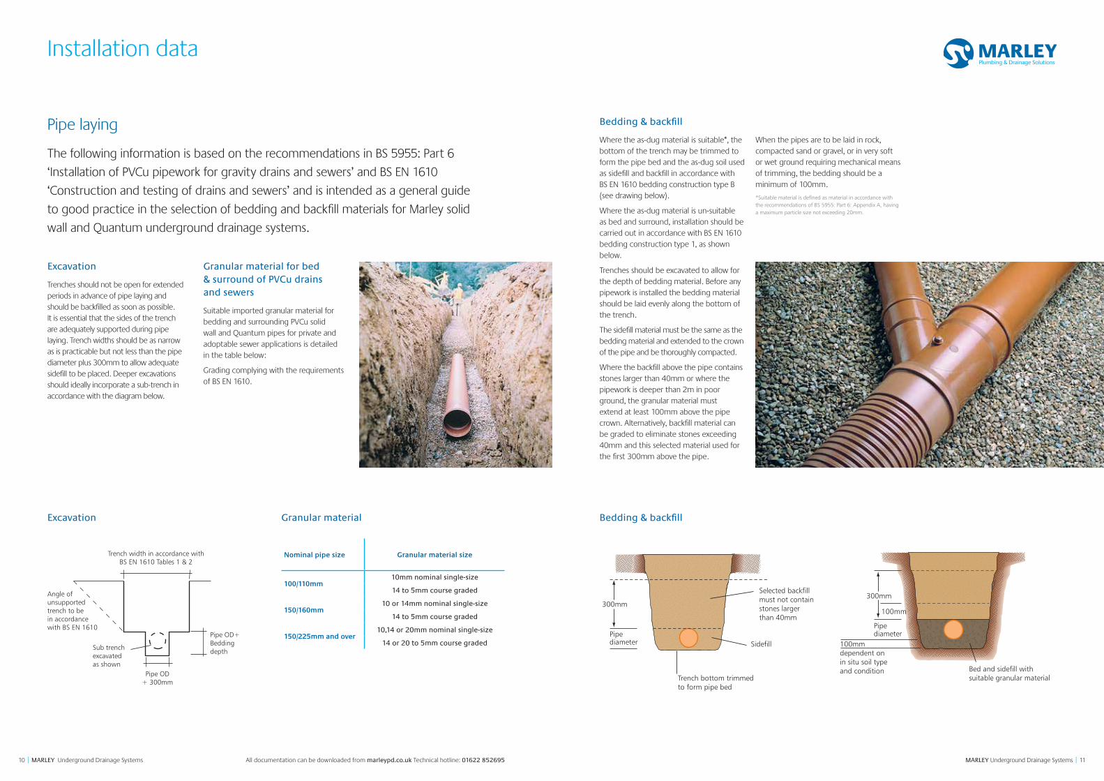
Excavation
Trenches should not be open for extended periods in advance of pipe laying and should be backfilled as soon as possible. It is essential that the sides of the trench are adequately supported during pipe laying. Trench widths should be as narrow as is practicable but not less than the pipe diameter plus 300mm to allow adequate sidefill to be placed. Deeper excavations should ideally incorporate a sub-trench in accordance with the diagram below.
Granular material for bed & surround of PVCu drains and sewers
Suitable imported granular material for bedding and surrounding PVCu solid wall and Quantum pipes for private and adoptable sewer applications is detailed in the table below:
Grading complying with the requirements of BS EN 1610.
Pipe laying
The following information is based on the recommendations in BS 5955: Part 6
‘Installation of PVCu pipework for gravity drains and sewers’ and BS EN 1610
‘Construction and testing of drains and sewers’ and is intended as a general guide
to good practice in the selection of bedding and backfill materials for Marley solid
wall and Quantum underground drainage systems.
Excavation
Angle of unsupported trench to bein accordance with BS EN 1610
Trench width in accordance withBS EN 1610 Tables 1 & 2
Pipe OD+ 300mm
Pipe OD+Bedding depthSub trench
excavatedas shown
Selected backfill must not contain stones larger than 40mm
SidefillPipediameter
300mm
Trench bottom trimmed to form pipe bed
Bed and sidefill withsuitable granular material
Pipediameter
300mm
100mm
100mmdependent on in situ soil type and condition
Granular material Bedding & backfill
Nominal pipe size Granular material size
100/110mm10mm nominal single-size
14 to 5mm course graded
150/160mm10 or 14mm nominal single-size
14 to 5mm course graded
150/225mm and over10,14 or 20mm nominal single-size
14 or 20 to 5mm course graded
1312 MARLEY Underground Drainage Systems || MARLEY Underground Drainage Systems For applications in accordance with DTP requirements, please refer to the technical design and installation guide,
available to download from marleypd.co.uk
Installation data
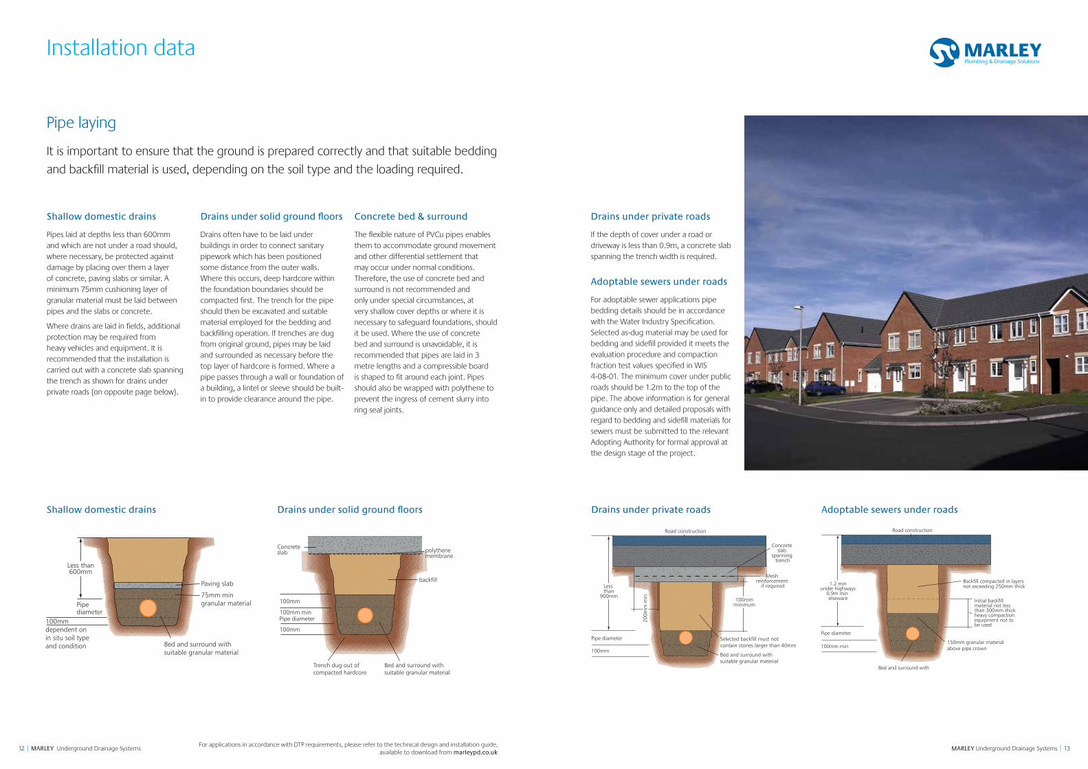
Shallow domestic drains
Pipes laid at depths less than 600mm and which are not under a road should, where necessary, be protected against damage by placing over them a layer of concrete, paving slabs or similar. A minimum 75mm cushioning layer of granular material must be laid between pipes and the slabs or concrete.
Where drains are laid in fields, additional protection may be required from heavy vehicles and equipment. It is recommended that the installation is carried out with a concrete slab spanning the trench as shown for drains under private roads (on opposite page below).
Concrete bed & surround
The flexible nature of PVCu pipes enables them to accommodate ground movement and other differential settlement that may occur under normal conditions. Therefore, the use of concrete bed and surround is not recommended and only under special circumstances, at very shallow cover depths or where it is necessary to safeguard foundations, should it be used. Where the use of concrete bed and surround is unavoidable, it is recommended that pipes are laid in 3 metre lengths and a compressible board is shaped to fit around each joint. Pipes should also be wrapped with polythene to prevent the ingress of cement slurry into ring seal joints.
Drains under private roads
If the depth of cover under a road or driveway is less than 0.9m, a concrete slab spanning the trench width is required.
Adoptable sewers under roads
For adoptable sewer applications pipe bedding details should be in accordance with the Water Industry Specification. Selected as-dug material may be used for bedding and sidefill provided it meets the evaluation procedure and compaction fraction test values specified in WIS 4-08-01. The minimum cover under public roads should be 1.2m to the top of the pipe. The above information is for general guidance only and detailed proposals with regard to bedding and sidefill materials for sewers must be submitted to the relevant Adopting Authority for formal approval at the design stage of the project.
Drains under solid ground floors
Drains often have to be laid under buildings in order to connect sanitary pipework which has been positioned some distance from the outer walls. Where this occurs, deep hardcore within the foundation boundaries should be compacted first. The trench for the pipe should then be excavated and suitable material employed for the bedding and backfilling operation. If trenches are dug from original ground, pipes may be laid and surrounded as necessary before the top layer of hardcore is formed. Where a pipe passes through a wall or foundation of a building, a lintel or sleeve should be built-in to provide clearance around the pipe.
Shallow domestic drains Drains under solid ground floors Drains under private roads Adoptable sewers under roads
Bed and surround withsuitable granular material
Paving slab
Pipediameter
Less than600mm
100mmdependent on in situ soil type and condition
75mm min granular material
Bed and surround with suitable granular material
Trench dug out of compacted hardcore
100mm minPipe diameter
100mm
100mm
Concrete slab
backfill
polythene membrane
Bed and surround withsuitable granular material
Selected backfill must not contain stones larger than 40mm
Pipe diameter
100mm
Less than
900mm100mm
minimum
Mesh reinforcement
if required
Road construction
Concrete slab
spanning trench
200m
m m
in
Bed and surround withsuitable granular material
150mm granular materialabove pipe crown
1.2 minunder highways
0.9m min elseware Initial backfill
material not less than 300mm thick heavy compactionequipment not to be used
Backfill compacted in layers not exceeding 250mm thick
Road construction
Pipe diameter
100mm min
Pipe laying
It is important to ensure that the ground is prepared correctly and that suitable bedding
and backfill material is used, depending on the soil type and the loading required.
1514 MARLEY Underground Drainage Systems || MARLEY Underground Drainage Systems All documentation can be downloaded from marleypd.co.uk Technical hotline: 01622 852695
Installation data
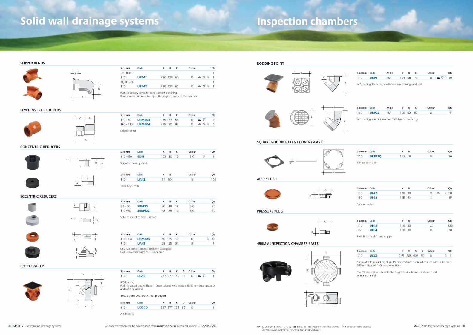
250mm inspection chambers
250mm inspection chambers may be used as an alternative to traditional manholes for invert depths up to 600mm. Intermediate depths can be accommodated by cutting the chamber riser using a hard tipped handsaw or similar.
The UCC7 is a one piece, level invert chamber with push-fit inlet and outlet sockets, making installation quick and easy.
Square or circular PVCu lids and frames are available for use with 250mm diameter inspection chambers and meet the loading requirements of BS EN 124 Class A15.
An alternative to the UCC7 is the level invert chamber base UAC44 with separate riser UAR1. Both square or circular lids and frames are suitable for use with this inspection chamber assembly.
Where the UCC7 or UAC44 inspection chambers are used to make a 90° change of direction in the drain, 45° bends should be fitted to the inlet and outlet connections to maintain a level invert through the chamber. It is also recommended that the peak flow in the drain is always discharged through the main channel and chambers are rotated accordingly on site to accommodate this.
250mm bottom outlet inspection chambers
The 250mm bottom outlet inspection chamber UAC02 provides a multiple collection point for branch drains from one or more dwellings and may also serve as a rodding and testing point for the main drain. The 110mm bottom outlet ensures that discharges from the side branches are quickly transmitted to the main drain which may be situated directly under the chamber or to one side at a lower level.
The bottom outlet chamber is ideal for situations where the main drain runs parallel to a building at a lower level as this allows the chamber to be positioned directly above the drain. Connection is then made using a back drop arrangement with a 45° branch and bend to the main drain.
Each chamber has four 110mm spigot inlets, three of which are open and the fourth can be opened for use if necessary. The UE43 plug can be used to blank off connections not required and the chamber riser UAR1 cut to accommodate invert depths of less than 600mm.
The UCL2 circular or UCL3 square lid and frame can be used to provide access to the chamber at ground level.
Local concrete surround
UCC7 250mm inspection chamber
UCL2 or UCL3 lid and frame
600mmmax
Bed and surround withsuitable granular material
Shallow inspection chambers
Local concrete surround
UAR1 riser
UAC02 chamber body
UCL2 or UCL3 lid and frame
600mm max
Bed and surround withsuitable granular material
UBL488long radius bend
Alternative 45ºbend & branch
UE407coupling
1716 MARLEY Underground Drainage Systems || MARLEY Underground Drainage Systems All documentation can be downloaded from marleypd.co.uk Technical hotline: 01622 852695
Installation data
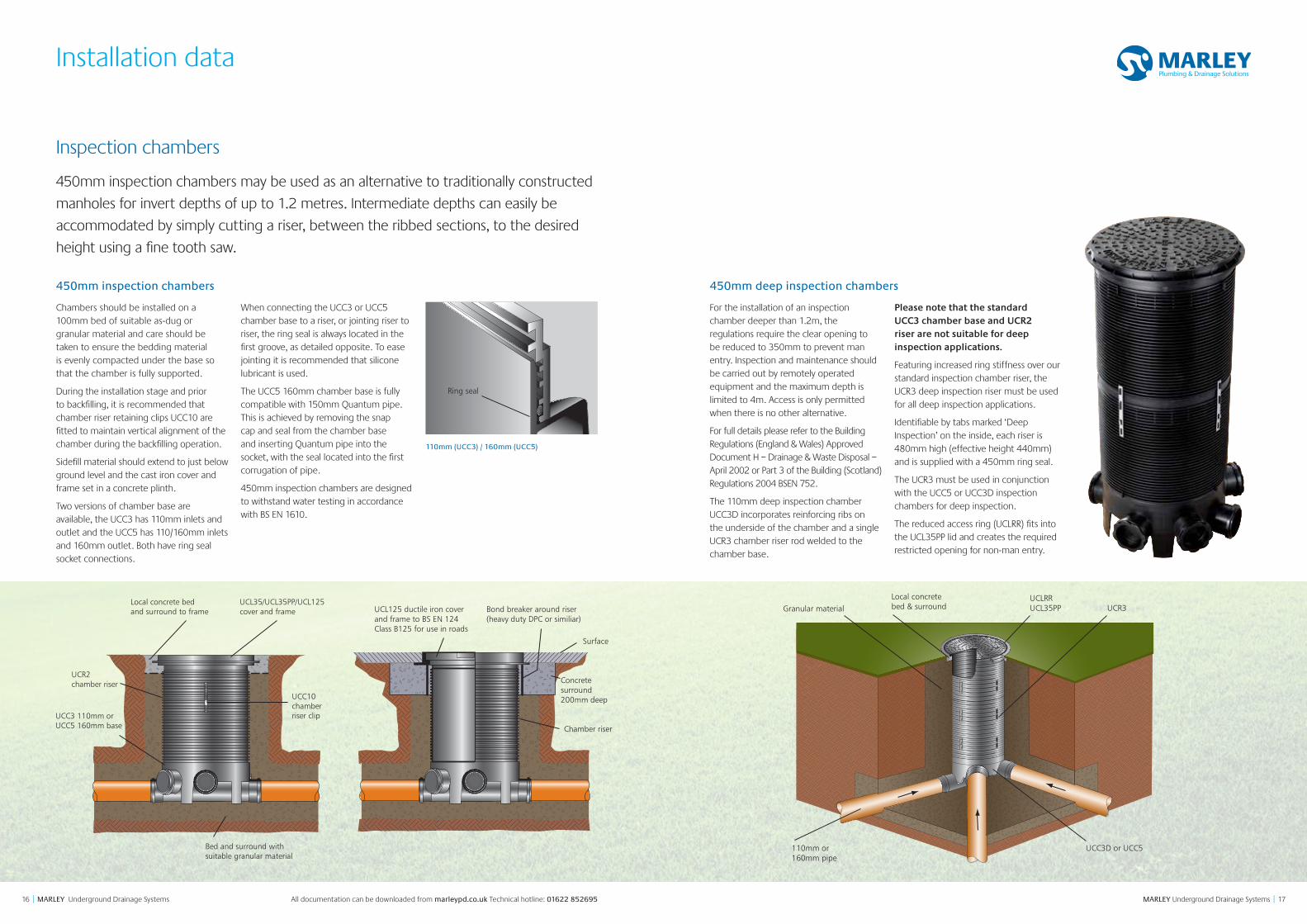
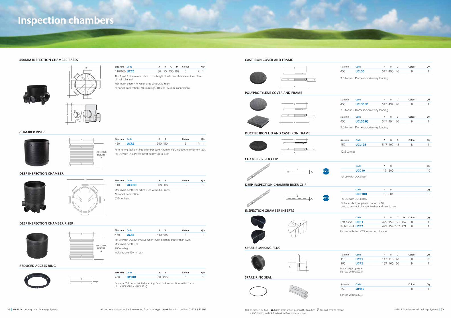
450mm inspection chambers
Chambers should be installed on a 100mm bed of suitable as-dug or granular material and care should be taken to ensure the bedding material is evenly compacted under the base so that the chamber is fully supported.
During the installation stage and prior to backfilling, it is recommended that chamber riser retaining clips UCC10 are fitted to maintain vertical alignment of the chamber during the backfilling operation.
Sidefill material should extend to just below ground level and the cast iron cover and frame set in a concrete plinth.
Two versions of chamber base are available, the UCC3 has 110mm inlets and outlet and the UCC5 has 110/160mm inlets and 160mm outlet. Both have ring seal socket connections.
When connecting the UCC3 or UCC5 chamber base to a riser, or jointing riser to riser, the ring seal is always located in the first groove, as detailed opposite. To ease jointing it is recommended that silicone lubricant is used.
The UCC5 160mm chamber base is fully compatible with 150mm Quantum pipe. This is achieved by removing the snap cap and seal from the chamber base and inserting Quantum pipe into the socket, with the seal located into the first corrugation of pipe.
450mm inspection chambers are designed to withstand water testing in accordance with BS EN 1610.
450mm deep inspection chambers
For the installation of an inspection chamber deeper than 1.2m, the regulations require the clear opening to be reduced to 350mm to prevent man entry. Inspection and maintenance should be carried out by remotely operated equipment and the maximum depth is limited to 4m. Access is only permitted when there is no other alternative.
For full details please refer to the Building Regulations (England & Wales) Approved Document H – Drainage & Waste Disposal – April 2002 or Part 3 of the Building (Scotland) Regulations 2004 BSEN 752.
The 110mm deep inspection chamber UCC3D incorporates reinforcing ribs on the underside of the chamber and a single UCR3 chamber riser rod welded to the chamber base.
Please note that the standard UCC3 chamber base and UCR2 riser are not suitable for deep inspection applications.
Featuring increased ring stiffness over our standard inspection chamber riser, the UCR3 deep inspection riser must be used for all deep inspection applications.
Identifiable by tabs marked ‘Deep Inspection’ on the inside, each riser is 480mm high (effective height 440mm) and is supplied with a 450mm ring seal.
The UCR3 must be used in conjunction with the UCC5 or UCC3D inspection chambers for deep inspection.
The reduced access ring (UCLRR) fits into the UCL35PP lid and creates the required restricted opening for non-man entry.
Granular material
110mm or 160mm pipe
UCC3D or UCC5
Local concrete bed & surround
UCLRRUCL35PP UCR3
UCL35/UCL35PP/UCL125cover and frame
UCC10chamber riser clip
Local concrete bed and surround to frame
UCR2 chamber riser
UCC3 110mm or UCC5 160mm base
Bed and surround withsuitable granular material
UCL125 ductile iron cover and frame to BS EN 124 Class B125 for use in roads
Bond breaker around riser(heavy duty DPC or similiar)
Surface
Concrete surround200mm deep
Chamber riser
Inspection chambers
450mm inspection chambers may be used as an alternative to traditionally constructed
manholes for invert depths of up to 1.2 metres. Intermediate depths can easily be
accommodated by simply cutting a riser, between the ribbed sections, to the desired
height using a fine tooth saw.
110mm (UCC3) / 160mm (UCC5)
Ring seal
1918 MARLEY Underground Drainage Systems || MARLEY Underground Drainage Systems All documentation can be downloaded from marleypd.co.uk Technical hotline: 01622 852695
Installation data
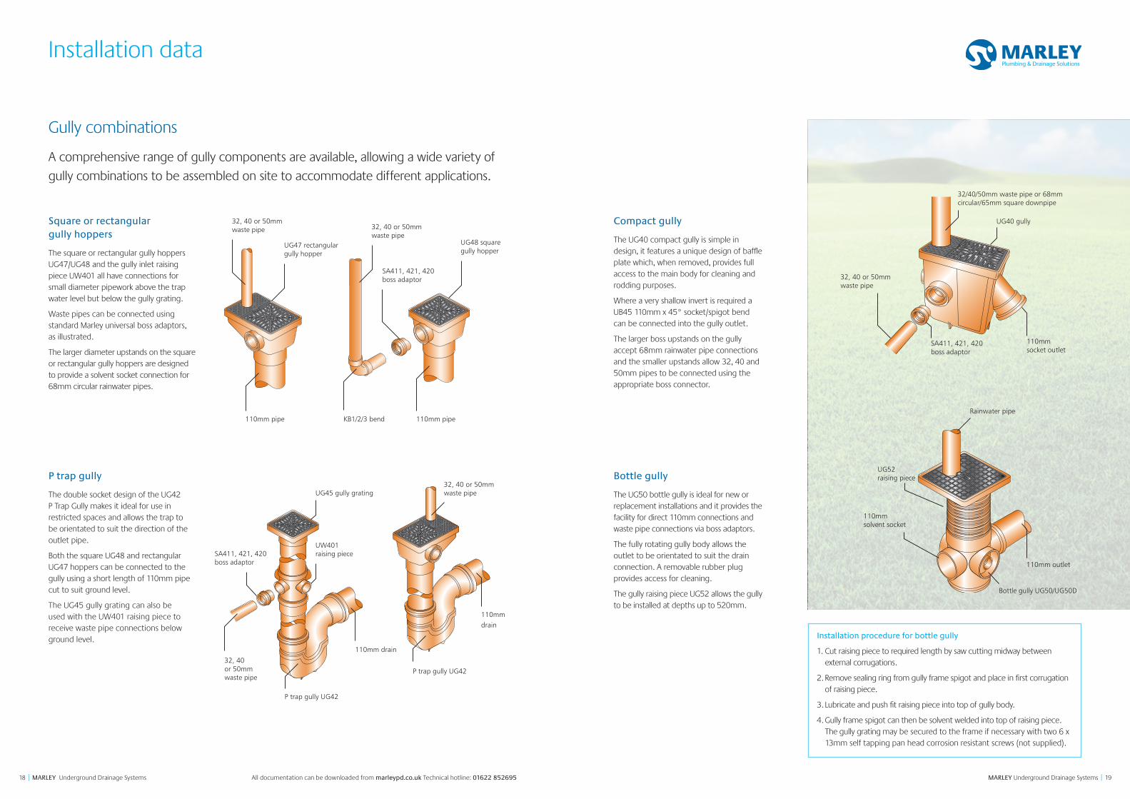
Square or rectangular gully hoppers
The square or rectangular gully hoppers UG47/UG48 and the gully inlet raising piece UW401 all have connections for small diameter pipework above the trap water level but below the gully grating.
Waste pipes can be connected using standard Marley universal boss adaptors, as illustrated.
The larger diameter upstands on the square or rectangular gully hoppers are designed to provide a solvent socket connection for 68mm circular rainwater pipes.
P trap gully
The double socket design of the UG42 P Trap Gully makes it ideal for use in restricted spaces and allows the trap to be orientated to suit the direction of the outlet pipe.
Both the square UG48 and rectangular UG47 hoppers can be connected to the gully using a short length of 110mm pipe cut to suit ground level.
The UG45 gully grating can also be used with the UW401 raising piece to receive waste pipe connections below ground level.
Compact gully
The UG40 compact gully is simple in design, it features a unique design of baffle plate which, when removed, provides full access to the main body for cleaning and rodding purposes.
Where a very shallow invert is required a UB45 110mm x 45° socket/spigot bend can be connected into the gully outlet.
The larger boss upstands on the gully accept 68mm rainwater pipe connections and the smaller upstands allow 32, 40 and 50mm pipes to be connected using the appropriate boss connector.
Bottle gully
The UG50 bottle gully is ideal for new or replacement installations and it provides the facility for direct 110mm connections and waste pipe connections via boss adaptors.
The fully rotating gully body allows the outlet to be orientated to suit the drain connection. A removable rubber plug provides access for cleaning.
The gully raising piece UG52 allows the gully to be installed at depths up to 520mm.
Gully combinations
A comprehensive range of gully components are available, allowing a wide variety of
gully combinations to be assembled on site to accommodate different applications.
32, 40 or 50mm waste pipe
SA411, 421, 420 boss adaptor
UG47 rectangular gully hopper
UG48 square gully hopper
32, 40 or 50mm waste pipe
110mm pipe 110mm pipeKB1/2/3 bend
32, 40 or 50mm waste pipe
P trap gully UG42
P trap gully UG42
110mm drain
110mm drain
UG45 gully grating
SA411, 421, 420 boss adaptor
UW401 raising piece
32, 40 or 50mm waste pipe
32, 40 or 50mm waste pipe
32/40/50mm waste pipe or 68mm circular/65mm square downpipe
UG40 gully
SA411, 421, 420 boss adaptor
110mm socket outlet
UG52 raising piece
110mm solvent socket
Rainwater pipe
Bottle gully UG50/UG50D
110mm outlet
Installation procedure for bottle gully
1. Cut raising piece to required length by saw cutting midway between external corrugations.
2. Remove sealing ring from gully frame spigot and place in first corrugation of raising piece.
3. Lubricate and push fit raising piece into top of gully body.
4. Gully frame spigot can then be solvent welded into top of raising piece. The gully grating may be secured to the frame if necessary with two 6 x 13mm self tapping pan head corrosion resistant screws (not supplied).
2120 MARLEY Underground Drainage Systems || MARLEY Underground Drainage Systems All documentation can be downloaded from marleypd.co.uk Technical hotline: 01622 852695
Installation data
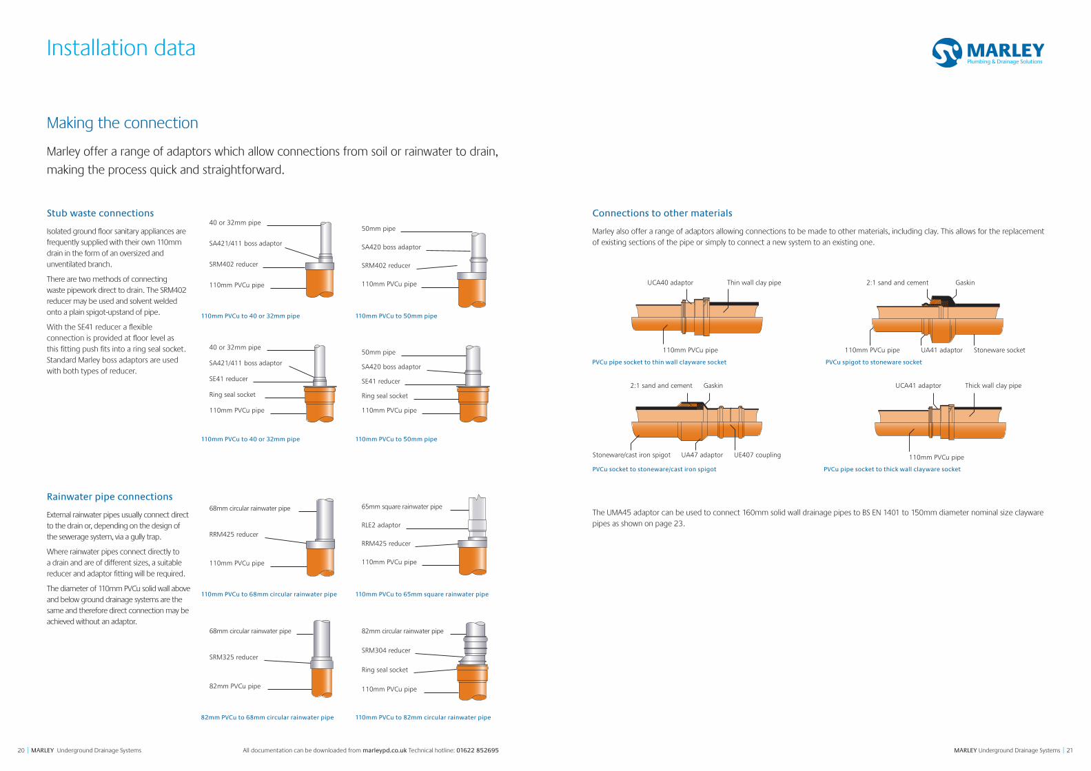
Stub waste connections
Isolated ground floor sanitary appliances are frequently supplied with their own 110mm drain in the form of an oversized and unventilated branch.
There are two methods of connecting waste pipework direct to drain. The SRM402 reducer may be used and solvent welded onto a plain spigot-upstand of pipe.
With the SE41 reducer a flexible connection is provided at floor level as this fitting push fits into a ring seal socket. Standard Marley boss adaptors are used with both types of reducer.
Connections to other materials
Marley also offer a range of adaptors allowing connections to be made to other materials, including clay. This allows for the replacement of existing sections of the pipe or simply to connect a new system to an existing one.
Rainwater pipe connections
External rainwater pipes usually connect direct to the drain or, depending on the design of the sewerage system, via a gully trap.
Where rainwater pipes connect directly to a drain and are of different sizes, a suitable reducer and adaptor fitting will be required.
The diameter of 110mm PVCu solid wall above and below ground drainage systems are the same and therefore direct connection may be achieved without an adaptor.
110mm PVCu to 50mm pipe110mm PVCu to 40 or 32mm pipe
110mm PVCu to 40 or 32mm pipe
50mm pipe
SRM402 reducer
SA420 boss adaptor
110mm PVCu pipe
40 or 32mm pipe
SRM402 reducer
SA421/411 boss adaptor
110mm PVCu pipe
110mm PVCu to 50mm pipe
50mm pipe
SE41 reducer
Ring seal socket
110mm PVCu pipe
SA420 boss adaptor
40 or 32mm pipe
SE41 reducer
Ring seal socket
110mm PVCu pipe
SA421/411 boss adaptor
110mm PVCu to 65mm square rainwater pipe110mm PVCu to 68mm circular rainwater pipe
82mm PVCu to 68mm circular rainwater pipe 110mm PVCu to 82mm circular rainwater pipe
68mm circular rainwater pipe
RRM425 reducer
110mm PVCu pipe
65mm square rainwater pipe
RRM425 reducer
RLE2 adaptor
110mm PVCu pipe
68mm circular rainwater pipe
SRM325 reducer
82mm PVCu pipe
82mm circular rainwater pipe
SRM304 reducer
Ring seal socket
110mm PVCu pipe
Making the connection
Marley offer a range of adaptors which allow connections from soil or rainwater to drain,
making the process quick and straightforward.
PVCu spigot to stoneware socketPVCu pipe socket to thin wall clayware socket
PVCu socket to stoneware/cast iron spigot PVCu pipe socket to thick wall clayware socket
110mm PVCu pipe
UCA40 adaptor Thin wall clay pipe
110mm PVCu pipe UA41 adaptor Stoneware socket
2:1 sand and cement Gaskin
Stoneware/cast iron spigot UA47 adaptor UE407 coupling
2:1 sand and cement Gaskin
110mm PVCu pipe
UCA41 adaptor Thick wall clay pipe
The UMA45 adaptor can be used to connect 160mm solid wall drainage pipes to BS EN 1401 to 150mm diameter nominal size clayware pipes as shown on page 23.
2322 MARLEY Underground Drainage Systems || MARLEY Underground Drainage Systems All documentation can be downloaded from marleypd.co.uk Technical hotline: 01622 852695
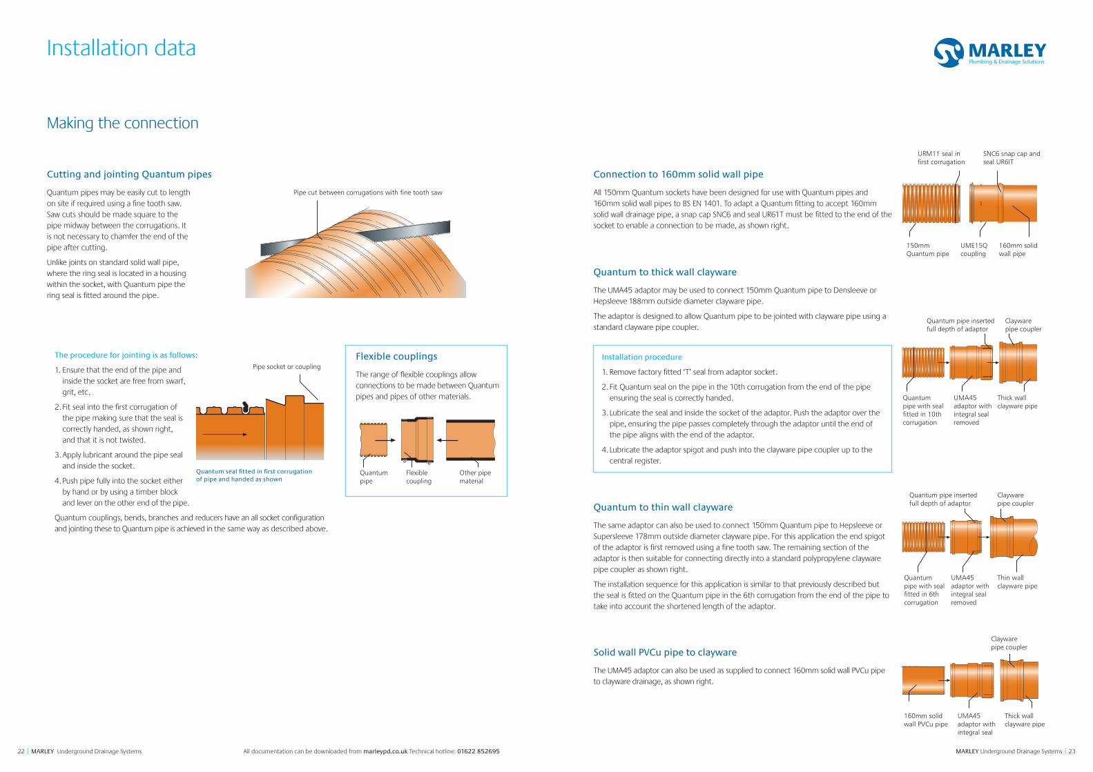
Cutting and jointing Quantum pipes
Quantum pipes may be easily cut to length on site if required using a fine tooth saw. Saw cuts should be made square to the pipe midway between the corrugations. It is not necessary to chamfer the end of the pipe after cutting.
Unlike joints on standard solid wall pipe, where the ring seal is located in a housing within the socket, with Quantum pipe the ring seal is fitted around the pipe.
Installation data
Making the connection
Pipe cut between corrugations with fine tooth saw
160mm solid wall pipe
150mm Quantum pipe
URM11 seal in first corrugation
SNC6 snap cap and seal UR6IT
UME15Q coupling
Thick wallclayware pipe
160mm solid wall PVCu pipe
Clayware pipe coupler
UMA45 adaptor with integral seal
Thick wall clayware pipe
Quantum pipe with seal fitted in 10th corrugation
Quantum pipe inserted full depth of adaptor
Clayware pipe coupler
UMA45 adaptor with integral seal removed
Thin wall clayware pipe
Quantum pipe with seal fitted in 6th corrugation
Quantum pipe inserted full depth of adaptor
Clayware pipe coupler
UMA45 adaptor with integral seal removed
Connection to 160mm solid wall pipe
All 150mm Quantum sockets have been designed for use with Quantum pipes and 160mm solid wall pipes to BS EN 1401. To adapt a Quantum fitting to accept 160mm solid wall drainage pipe, a snap cap SNC6 and seal UR61T must be fitted to the end of the socket to enable a connection to be made, as shown right.
Quantum to thick wall clayware
The UMA45 adaptor may be used to connect 150mm Quantum pipe to Densleeve or Hepsleeve 188mm outside diameter clayware pipe.
The adaptor is designed to allow Quantum pipe to be jointed with clayware pipe using a standard clayware pipe coupler.
Quantum to thin wall clayware
The same adaptor can also be used to connect 150mm Quantum pipe to Hepsleeve or Supersleeve 178mm outside diameter clayware pipe. For this application the end spigot of the adaptor is first removed using a fine tooth saw. The remaining section of the adaptor is then suitable for connecting directly into a standard polypropylene clayware pipe coupler as shown right.
The installation sequence for this application is similar to that previously described but the seal is fitted on the Quantum pipe in the 6th corrugation from the end of the pipe to take into account the shortened length of the adaptor.
Solid wall PVCu pipe to clayware
The UMA45 adaptor can also be used as supplied to connect 160mm solid wall PVCu pipe to clayware drainage, as shown right.
The procedure for jointing is as follows:
1. Ensure that the end of the pipe and inside the socket are free from swarf, grit, etc.
2. Fit seal into the first corrugation of the pipe making sure that the seal is correctly handed, as shown right, and that it is not twisted.
3. Apply lubricant around the pipe seal and inside the socket.
4. Push pipe fully into the socket either by hand or by using a timber block and lever on the other end of the pipe.
Quantum couplings, bends, branches and reducers have an all socket configuration and jointing these to Quantum pipe is achieved in the same way as described above.
Pipe socket or coupling
Quantum seal fitted in first corrugation of pipe and handed as shown
Flexible couplings
The range of flexible couplings allow connections to be made between Quantum pipes and pipes of other materials.
Flexible coupling
Other pipe material
Quantum pipe
Installation procedure
1. Remove factory fitted ‘T’ seal from adaptor socket.
2. Fit Quantum seal on the pipe in the 10th corrugation from the end of the pipe ensuring the seal is correctly handed.
3. Lubricate the seal and inside the socket of the adaptor. Push the adaptor over the pipe, ensuring the pipe passes completely through the adaptor until the end of the pipe aligns with the end of the adaptor.
4. Lubricate the adaptor spigot and push into the clayware pipe coupler up to the central register.
2524 MARLEY Underground Drainage Systems || MARLEY Underground Drainage Systems All documentation can be downloaded from marleypd.co.uk Technical hotline: 01622 852695
Standards
BS 4660 & BS EN 1401 Thermoplastics ancillary fittings of nominal sizes 110 and 160 for below ground gravity drainage and sewerage.
BS 4962 Specification for plastic pipes and fittings for use as subsoil field drains.
BS EN 14680 Adhesives for non-pressure thermoplastic pipe systems.
BS 7158 Plastic inspection chambers for drains and sewers.
BS EN 124 Gully tops and manhole tops for vehicular and pedestrian areas. Design requirements, type testing, marking, quality control.
BS EN 295 Vitrified clay pipes & fittings and pipe joints for drains and sewers.
BS EN 681-1 Elastomeric seals. Material requirements for pipe joint seals used in water and drainage applications.
BS EN 752 Drain & Sewer Systems outside buildings.
BS EN 1295-1 Structural design of buried pipelines under various conditions of loading. General requirements.
BS EN 1610 Construction & Testing of Drains & Sewers.
BS EN 13476-3 Plastics piping systems for non-pressure drainage and sewerage, structured wall piping systems with smooth bore and profiled external surface.
BS EN ISO 9001: 2008 Quality management systems.
BS EN ISO 14001: 2004 Environmental management systems requirements with guidance for use.
BBA 11/H172 Quantum Highway Drainage System. 375-600mm pipes and couplings.
BBA 88/1977 Marley Underground Drainage System.
BBA 09/H146 Quantum Highway PVCu Twinwall Drainage System.
BBA 94/2985 Marley Quantum Sewer PVCu Twinwall Underground Drainage and Sewerage System.
BBA 98/3486 Marley Quantum Highway PVCu Twinwall Surface Water Drainage System.
WIS 4-08-01 Bedding and sidefill materials for buried pipelines.
Certificate No. 88/1977 94/2985 98/3486 09/H146 11/H172
British & European Standards
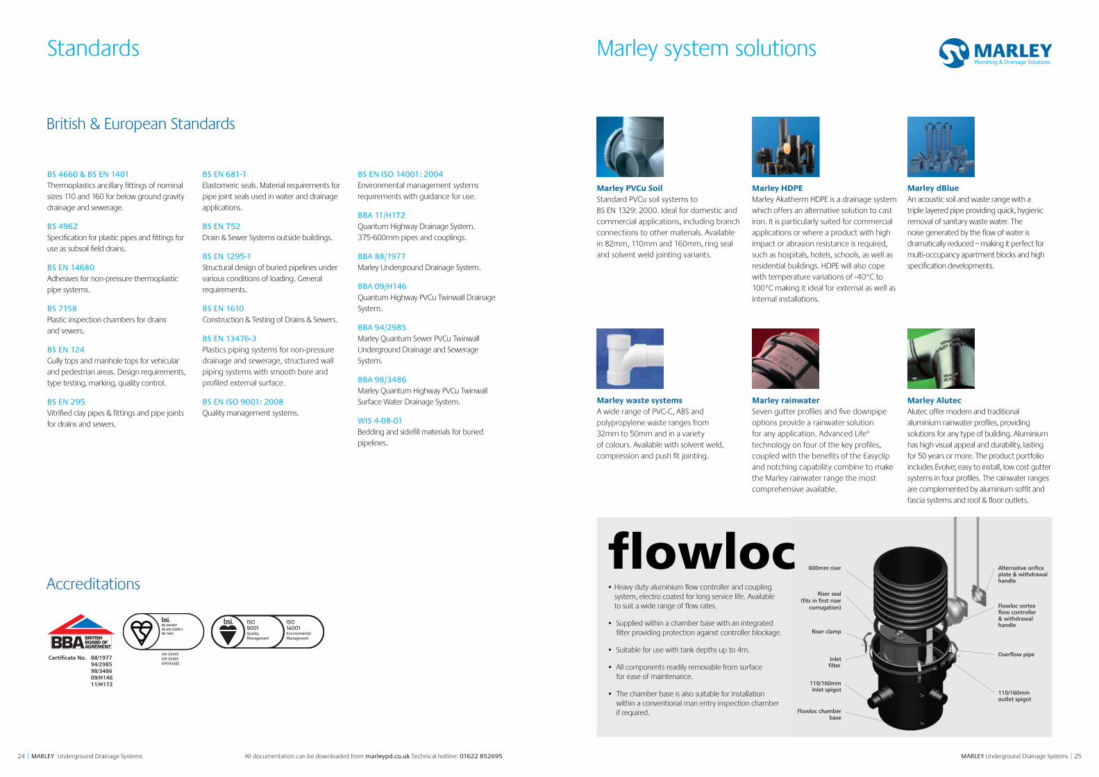
Marley PVCu Soil Standard PVCu soil systems to BS EN 1329: 2000. Ideal for domestic and commercial applications, including branch connections to other materials. Available in 82mm, 110mm and 160mm, ring seal and solvent weld jointing variants.
Marley HDPE Marley Akatherm HDPE is a drainage system which offers an alternative solution to cast iron. It is particularly suited for commercial applications or where a product with high impact or abrasion resistance is required, such as hospitals, hotels, schools, as well as residential buildings. HDPE will also cope with temperature variations of -40°C to 100°C making it ideal for external as well as internal installations.
Marley dBlue An acoustic soil and waste range with a triple layered pipe providing quick, hygienic removal of sanitary waste water. The noise generated by the flow of water is dramatically reduced – making it perfect for multi-occupancy apartment blocks and high specification developments.
Marley waste systems A wide range of PVC-C, ABS and polypropylene waste ranges from 32mm to 50mm and in a variety of colours. Available with solvent weld, compression and push fit jointing.
Marley rainwater Seven gutter profiles and five downpipe options provide a rainwater solution for any application. Advanced Life4 technology on four of the key profiles, coupled with the benefits of the Easyclip and notching capability combine to make the Marley rainwater range the most comprehensive available.
Marley Alutec Alutec offer modern and traditional aluminium rainwater profiles, providing solutions for any type of building. Aluminium has high visual appeal and durability, lasting for 50 years or more. The product portfolio includes Evolve; easy to install, low cost gutter systems in four profiles. The rainwater ranges are complemented by aluminium soffit and fascia systems and roof & floor outlets.
Accreditations
Marley system solutions
KM 05495KM 05495KM542682
• Heavy duty aluminium flow controller and coupling system, electro coated for long service life. Available to suit a wide range of flow rates.
• Supplied within a chamber base with an integrated filter providing protection against controller blockage.
• Suitable for use with tank depths up to 4m.
• All components readily removable from surface for ease of maintenance.
• The chamber base is also suitable for installation within a conventional man entry inspection chamber if required.
600mm riser
Riser seal(fits in first riser
corrugation)
Riser clamp
110/160mmInlet spigot
Flowloc chamberbase
110/160mm
Overflow pipe
outlet spigot
Inletfilter
Flowloc vortex flow controller& withdrawalhandle
Alternative orificeplate & withdrawalhandle
272726 MARLEY Underground Drainage Systems || MARLEY Underground Drainage Systems All documentation can be downloaded from marleypd.co.uk Technical hotline: 01622 852695
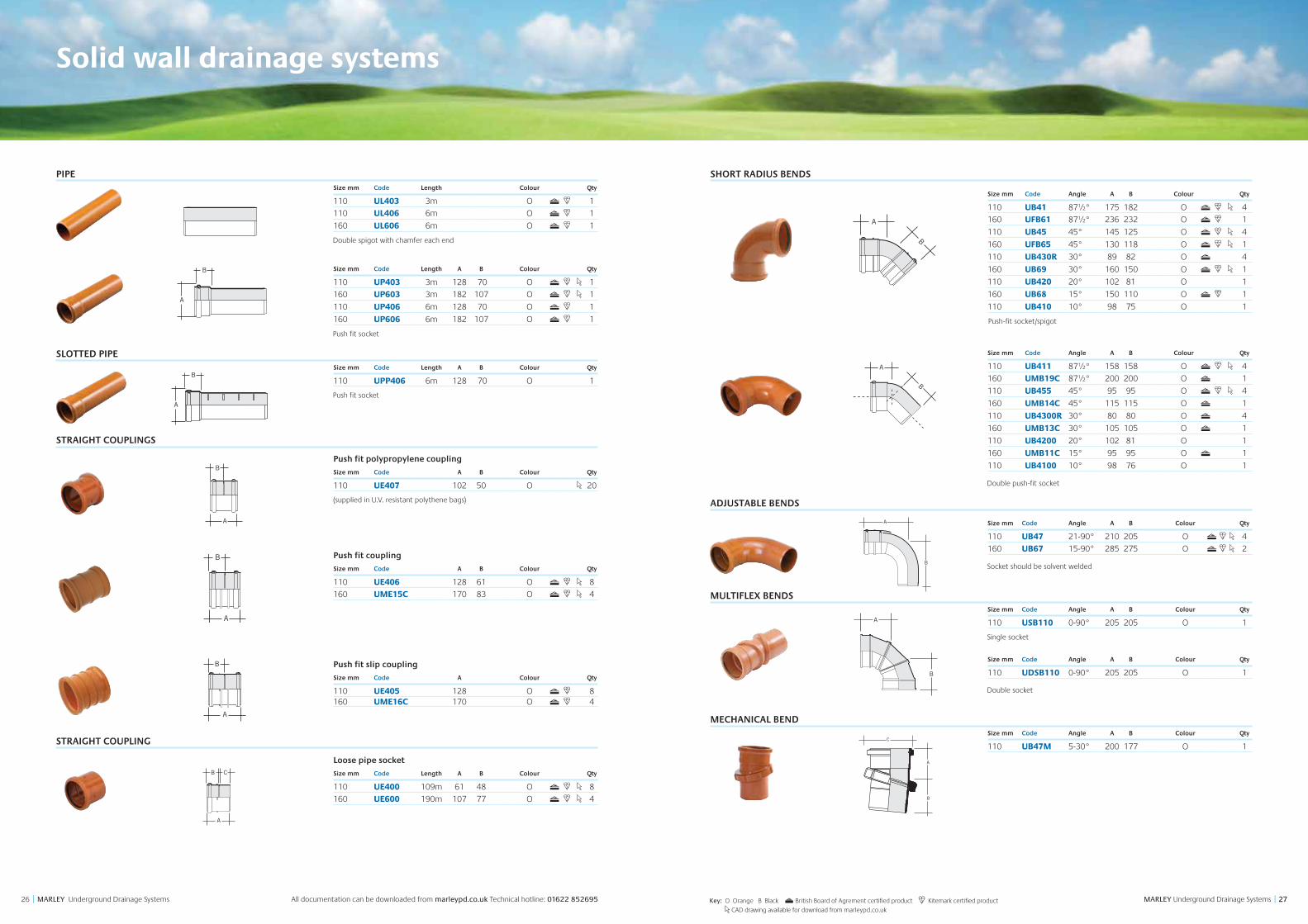
Solid wall drainage systems
SHORT RADIUS BENDS
Size mm Code Angle A B Colour Qty
110 UB41 87½° 175 182 O 4
160 UFB61 87½° 236 232 O 1
110 UB45 45° 145 125 O 4
160 UFB65 45° 130 118 O 1
110 UB430R 30° 89 82 O 4
160 UB69 30° 160 150 O 1
110 UB420 20° 102 81 O 1
160 UB68 15° 150 110 O 1
110 UB410 10° 98 75 O 1
Push-fit socket/spigot
Size mm Code Angle A B Colour Qty
110 UB411 87½° 158 158 O 4
160 UMB19C 87½° 200 200 O 1
110 UB455 45° 95 95 O 4
160 UMB14C 45° 115 115 O 1
110 UB4300R 30° 80 80 O 4
160 UMB13C 30° 105 105 O 1
110 UB4200 20° 102 81 O 1
160 UMB11C 15° 95 95 O 1
110 UB4100 10° 98 76 O 1
Double push-fit socket
ADJUSTABLE BENDS
Size mm Code Angle A B Colour Qty
110 UB47 21-90° 210 205 O 4
160 UB67 15-90° 285 275 O 2
Socket should be solvent welded
MULTIFLEX BENDSSize mm Code Angle A B Colour Qty
110 USB110 0-90° 205 205 O 1
Single socket
Size mm Code Angle A B Colour Qty
110 UDSB110 0-90° 205 205 O 1
Double socket
MECHANICAL BENDSize mm Code Angle A B Colour Qty
110 UB47M 5-30° 200 177 O 1
PIPESize mm Code Length Colour Qty
110 UL403 3m O 1
110 UL406 6m O 1
160 UL606 6m O 1
Double spigot with chamfer each end
Size mm Code Length A B Colour Qty
110 UP403 3m 128 70 O 1
160 UP603 3m 182 107 O 1
110 UP406 6m 128 70 O 1
160 UP606 6m 182 107 O 1
Push fit socket
SLOTTED PIPESize mm Code Length A B Colour Qty
110 UPP406 6m 128 70 O 1
Push fit socket
STRAIGHT COUPLINGS
Push fit polypropylene coupling
Size mm Code A B Colour Qty
110 UE407 102 50 O 20
(supplied in U.V. resistant polythene bags)
Push fit coupling
Size mm Code A B Colour Qty
110 UE406 128 61 O 8
160 UME15C 170 83 O 4
Push fit slip coupling
Size mm Code A Colour Qty
110 UE405 128 O 8160 UME16C 170 O 4
STRAIGHT COUPLING
Loose pipe socket
Size mm Code Length A B Colour Qty
110 UE400 109m 61 48 O 8
160 UE600 190m 107 77 O 4
B
A
B
A
A
B
B
A
B
A
B
A
A
B
B
A
A
B
B
A
B
A
B
A
A
B
B
A
B
A
B
A
A
B
B
A
B
A
B
A
A
B
A
B
A
B
A
C
B
A
Key: O Orange B Black British Board of Agrement certified product Kitemark certified product
CAD drawing available for download from marleypd.co.uk
A
B
A
B
B
AC
B
A
R
B
A
C
C
A
B
292928 MARLEY Underground Drainage Systems || MARLEY Underground Drainage Systems All documentation can be downloaded from marleypd.co.uk Technical hotline: 01622 852695
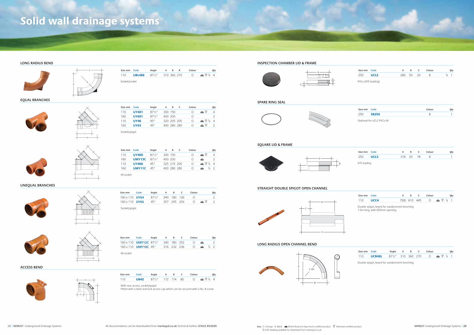
LONG RADIUS BEND
Size mm Code Angle A B R Colour Qty
110 UBL488 87½° 310 360 270 O 4
Socket/socket
EQUAL BRANCHES
Size mm Code Angle A B C Colour Qty
110 UY401 87½° 300 150 O 4
160 UY601 87½° 400 200 O 2
110 UY46 45° 320 205 205 O 4
160 UY63 45° 400 280 280 O 2
Socket/spigot
Size mm Code Angle A B C Colour Qty
110 UY400 87½° 300 150 O 4
160 UMY13C 87½° 400 200 O 2
110 UY466 45° 325 215 200 O 4
160 UMY11C 45° 400 280 280 O 2
All socket
UNEQUAL BRANCHES
Size mm Code Angle A B C Colour Qty
160 x 110 UY64 87½° 340 180 126 O 2
160 x 110 UY66 45° 357 245 254 O 2
Socket/spigot
Size mm Code Angle A B C Colour Qty
160 x 110 UMY12C 87½° 340 180 252 O 2
160 x 110 UMY10C 45° 316 232 236 O 2
All socket
ACCESS BEND
Size mm Code Angle A B C Colour Qty
110 UB42 87½° 172 174 80 O 4
With rear access, socket/spigot Fitted with a twist and lock access cap which can be secured with a No. 8 screw
B
A
C
B
AC
B
A
C
B
A
C
D
A
B
B
AC
B
A
R
B
A
C
B
A
C
B
AC
B
A
C
B
A
C
D
B
A
C
B
AC
B
A
C
B
A
C
D
Solid wall drainage systems
A
BR
Key: O Orange B Black British Board of Agrement certified product Kitemark certified product
CAD drawing available for download from marleypd.co.uk
A
BC
INSPECTION CHAMBER LID & FRAME
Size mm Code A B C Colour Qty
250 UCL2 280 50 20 B 1
PVCu (A15 loading)
SPARE RING SEAL
Size mm Code Colour Qty
250 SR250 B 1
Optional for UCL2 PVCu lid
SQUARE LID & FRAME
Size mm Code A B C Colour Qty
250 UCL3 318 20 78 B 1
A15 loading
STRAIGHT DOUBLE SPIGOT OPEN CHANNEL
Size mm Code A B C Colour Qty
110 UCC4 1500 610 445 O 1
Double spigot, keyed for sand/cement benching 1.5m long, with 600mm opening
LONG RADIUS OPEN CHANNEL BEND
Size mm Code Angle A B C Colour Qty
110 UCB48L 87½° 310 360 270 O 1
Double spigot, keyed for sand/cement benching
B
A
C
A
B
C
A
B
C (R)
B
A
C
A
B
C
B
A
C
B
A
C
B
AC
313130 MARLEY Underground Drainage Systems || MARLEY Underground Drainage Systems All documentation can be downloaded from marleypd.co.uk Technical hotline: 01622 852695
SLIPPER BENDSSize mm Code A B C Colour Qty
Left hand 1
110 USB41 230 120 65 O 1
Right hand 1
110 USB42 230 120 65 O 1
Push-fit socket, keyed for sand/cement benching. Bend may be trimmed to adjust the angle of entry to the manhole.
LEVEL INVERT REDUCERSSize mm Code A B C Colour Qty
110 – 82 URM304 135 67 54 O 4
160 – 110 URM604 219 90 82 O 4
Spigot/socket
CONCENTRIC REDUCERSSize mm Code A B C Colour Qty
110 – 50 SE41 103 80 19 B G 1
Spigot to boss upstand
Size mm Code A B Colour Qty
110 UA42 31 104 B 100
110 x 68/65mm
ECCENTRIC REDUCERSSize mm Code A B C Colour Qty
82 – 50 SRM30 70 48 19 B G 90
110 – 50 SRM402 48 25 19 B G 10
Solvent socket to boss upstand
Size mm Code A B C Colour Qty
110 – 68 URM425 40 25 12 O 10
110 UA43 58 25 34 B 1
URM425 Solvent socket to 68mm downpipe UA43 Universal waste to 110mm drain
BOTTLE GULLYSize mm Code A B C D Colour Qty
110 UG50 237 277 152 95 O 1
A15 loading Push fit socket outlet, three 110mm solvent weld inlets with 50mm boss upstands and rodding access
Bottle gully with back inlet plugged
Size mm Code A B C D Colour Qty
110 UG50D 237 277 152 95 O 1
A15 loading
B
A
C
B
A
C
B
AC
B
A
B
A
D
C
B
A
C
C
C
AB
AB
B AC
B
A
C
C
C
AB
AB
B AC
UA42/RA42
A
B
UA43/SA110
A
CB
B
AC
Solid wall drainage systems
CAB
CAB
B
A
B
A
A
B
A
C
B
C B
A
C
B
A
CA
B
C
A
BD
110mm 500mm
750mm
12
3
BA
AB
Key: O Orange B Black G Grey British Board of Agrement certified product Kitemark certified product
CAD drawing available for download from marleypd.co.uk
RODDING POINT
Size mm Code Angle A B C Colour Qty
110 URP1 45° 164 68 70 O 10
A15 loading. Black cover with four screw fixings and seal
Size mm Code Angle A B C Colour Qty
160 URP2C 45° 190 92 89 O 4
A15 loading. Aluminium cover with two screw fixings
SQUARE RODDING POINT COVER (SPARE)
Size mm Code A B Colour Qty
110 URPFSQ 163 18 B 10
For use with URP1
ACCESS CAP
Size mm Code A B Colour Qty
110 UE42 130 30 O 50
160 UE62 195 40 O 15
Solvent socket
PRESSURE PLUG
Size mm Code A B Colour Qty
110 UE43 110 30 O 135
160 UE64 160 30 O 30
Push fits into plain end of pipe
450MM INSPECTION CHAMBER BASES
Size mm Code A B C D Colour Qty
110 UCC3 245 608 608 50 B 1
Supplied with 4 blanking plugs. Max invert depth 1.2m (when used with UCR2 riser). 245mm high. All 110mm connections.
The ‘D’ dimension relates to the height of side branches above invert of main channel
B
A
B
A
B
A
C
AD
B
C
AD
B
B
AT W I S T T O LO C KT W I S T T O LO C K
Inspection chambers
A
B
C
A
B
C C
B
A
C
B
A
A
B
A
B
333332 MARLEY Underground Drainage Systems || MARLEY Underground Drainage Systems All documentation can be downloaded from marleypd.co.uk Technical hotline: 01622 852695
450MM INSPECTION CHAMBER BASES
Size mm Code A B C D Colour Qty
110/160 UCC5 80 75 490 192 B 1
The A and B dimensions relate to the height of side branches above invert level of main channel.
Max invert depth 4m (when used with UCR3 riser)
All socket connections. 400mm high, 110 and 160mm, connections.
CHAMBER RISER
Size mm Code A B Colour Qty
450 UCR2 390 450 B 1
Push fit ring seal joint into chamber base. 430mm high, includes one 450mm seal.
For use with UCC3/5 for invert depths up to 1.2m
DEEP INSPECTION CHAMBER
Size mm Code A B Colour Qty
110 UCC3D 608 608 B 1
Max invert depth 4m (when used with UCR3 riser)
All socket connections.
655mm high
DEEP INSPECTION CHAMBER RISER
Size mm Code A B Colour Qty
450 UCR3 410 488 B 1
For use with UCC3D or UCC5 when invert depth is greater than 1.2m.
Max invert depth 4m
480mm high
Includes one 450mm seal
REDUCED ACCESS RING
Size mm Code A B Colour Qty
450 UCLRR 60 455 B 1
Provides 350mm restricted opening. Snap lock connection to the frame of the UCL35PP and UCL35SQ
EFFECTIVEHEIGHT
A
B
EFFECTIVEHEIGHT
A
B
C
A
D
B
B
A
A
B
Key: O Orange B Black British Board of Agrement certified product Kitemark certified product
CAD drawing available for download from marleypd.co.uk
Inspection chambers
CAST IRON COVER AND FRAME
Size mm Code A B C Colour Qty
450 UCL35 517 490 40 B 1
3.5 tonnes. Domestic driveway loading
POLYPROPYLENE COVER AND FRAME
Size mm Code A B C Colour Qty
450 UCL35PP 547 494 70 B 1
3.5 tonnes. Domestic driveway loading
Size mm Code A B C Colour Qty
450 UCL35SQ 547 494 70 B 1
3.5 tonnes. Domestic driveway loading
DUCTILE IRON LID AND CAST IRON FRAME
Size mm Code A B C Colour Qty
450 UCL125 547 492 48 B 1 12.5 tonnes
CHAMBER RISER CLIP
Code A B Qty
UCC10 19 200 10
For use with UCR2 riser
DEEP INSPECTION CHAMBER RISER CLIPCode A B Qty
UCC10D 19 204 10
For use with UCR3 riser.
Zintec coated, supplied in packet of 10. Used to connect chamber to riser and riser to riser.
INSPECTION CHAMBER INSERTS
Code A B C D Colour Qty
Left hand UCB1 425 159 171 167 B 1
Right hand UCB2 425 159 167 171 B 1
For use with the UCC5 inspection chamber
SPARE BLANKING PLUG
Size mm Code A B C Colour Qty
110 UCP1 117 110 40 B 70
160 UCP2 165 160 60 B 1
Black polypropylene For use with UCC3/5
SPARE RING SEAL
Size mm Code Colour Qty
450 SR450 B 1
For use with UCR2/3
C
D
B A
A
D
B
C
A160
490
660
871/2º
45º
45º
B
EFFECTIVEHEIGHT
A
BA
B
A
C
B871/2º
400
A
D
B
C
A160
490
660
871/2º
45º
45º
B
EFFECTIVEHEIGHT
A
BA
B
A
C
B871/2º
400
BA
C
BA
A
B
A
B
A
A
D
B
C
A160
490
660
871/2º
45º
45º
B
EFFECTIVEHEIGHT
A
BA
B
A
C
B871/2º
400
A
D
B
C
A160
490
660
871/2º
45º
45º
B
EFFECTIVEHEIGHT
A
BA
B
A
C
B871/2º
400
PK10
PK10
A
D
B
C
A160
490
660
871/2º
45º
45º
B
EFFECTIVEHEIGHT
A
BA
B
A
C
B871/2º
400
A
D
B
C
A160
490
660
871/2º
45º
45º
B
EFFECTIVEHEIGHT
A
BA
B
A
C
B871/2º
400
A
D
B
C
A160
490
660
871/2º
45º
45º
B
EFFECTIVEHEIGHT
A
BA
B
A
C
B871/2º
400
353534 MARLEY Underground Drainage Systems || MARLEY Underground Drainage Systems All documentation can be downloaded from marleypd.co.uk Technical hotline: 01622 852695
Inspection chambers
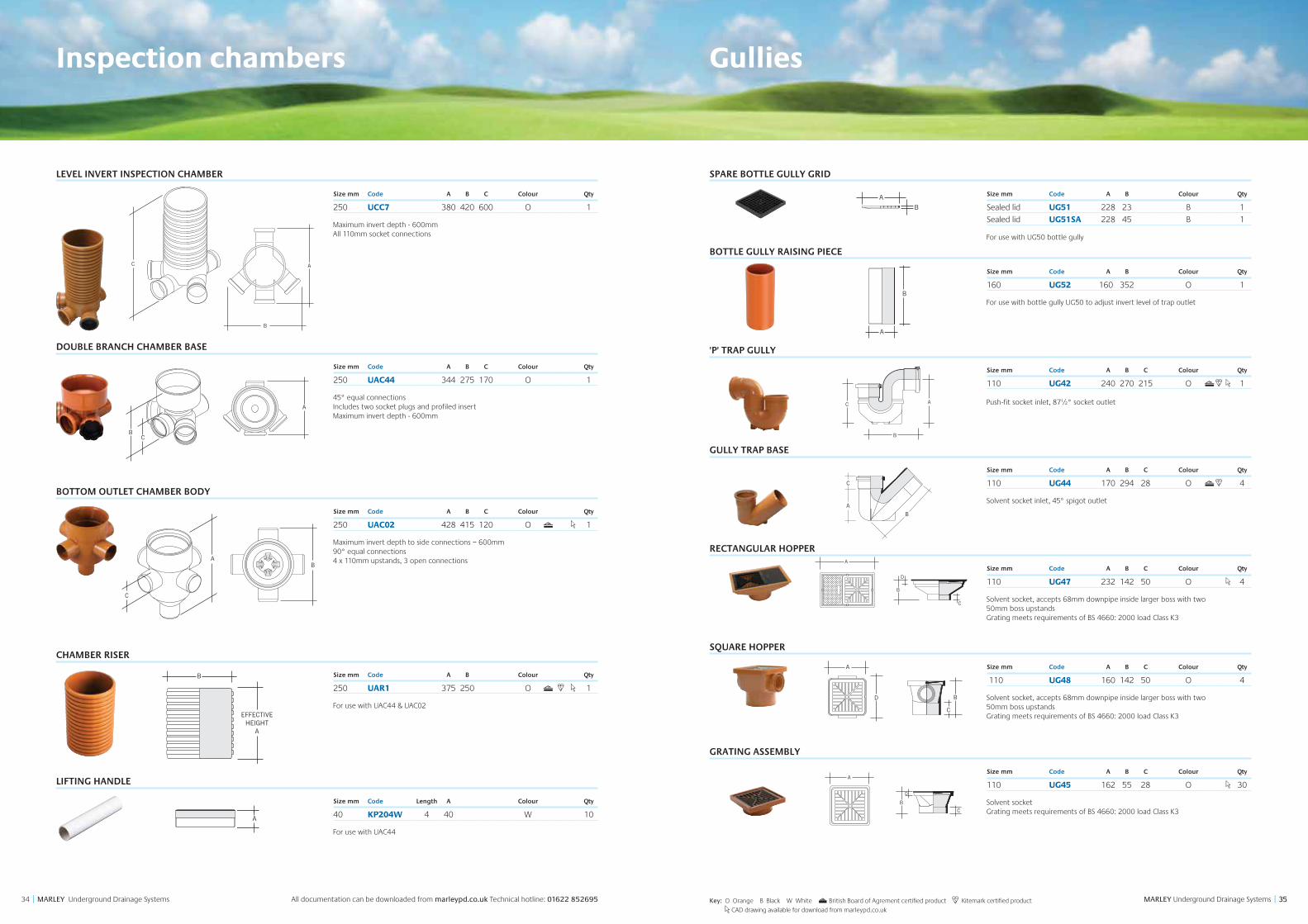
LEVEL INVERT INSPECTION CHAMBER
Size mm Code A B C Colour Qty
250 UCC7 380 420 600 O 1
Maximum invert depth - 600mm All 110mm socket connections
DOUBLE BRANCH CHAMBER BASE
Size mm Code A B C Colour Qty
250 UAC44 344 275 170 O 1
45° equal connections Includes two socket plugs and profiled insert Maximum invert depth - 600mm
BOTTOM OUTLET CHAMBER BODY
Size mm Code A B C Colour Qty
250 UAC02 428 415 120 O 1
Maximum invert depth to side connections – 600mm 90° equal connections 4 x 110mm upstands, 3 open connections
CHAMBER RISER
Size mm Code A B Colour Qty
250 UAR1 375 250 O 1
For use with UAC44 & UAC02
LIFTING HANDLE
Size mm Code Length A Colour Qty
40 KP204W 4 40 W 10
For use with UAC44
B
A
A
B
C
C
BA
C
B
A
B
EFFECTIVEHEIGHT
A
B
A
A
B
C
C
BA
C
B
A
B
A
A
B
C
C
BA
C
B
A
B
A
A
B
C
C
BA
C
B
A
B
A
A
B
C
C
BA
C
B
A
B
A
A
B
C
C
BA
C
B
A
B
A
B
A
C
B
A
B
A
B
A
B
A
A
B
C
C
BA
C
B
A
B
A
A
B
C
C
BA
C
B
A
Key: O Orange B Black W White British Board of Agrement certified product Kitemark certified product
CAD drawing available for download from marleypd.co.uk
Gullies
SPARE BOTTLE GULLY GRID
Size mm Code A B Colour Qty
Sealed lid UG51 228 23 B 1
Sealed lid UG51SA 228 45 B 1
For use with UG50 bottle gully
BOTTLE GULLY RAISING PIECE
Size mm Code A B Colour Qty
160 UG52 160 352 O 1
For use with bottle gully UG50 to adjust invert level of trap outlet
'P' TRAP GULLY
Size mm Code A B C Colour Qty
110 UG42 240 270 215 O 1
Push-fit socket inlet, 87½° socket outlet
GULLY TRAP BASE
Size mm Code A B C Colour Qty
110 UG44 170 294 28 O 4
Solvent socket inlet, 45° spigot outlet
RECTANGULAR HOPPER
Size mm Code A B C Colour Qty
110 UG47 232 142 50 O 4
Solvent socket, accepts 68mm downpipe inside larger boss with two 50mm boss upstands Grating meets requirements of BS 4660: 2000 load Class K3
SQUARE HOPPER
Size mm Code A B C Colour Qty
110 UG48 160 142 50 O 4
Solvent socket, accepts 68mm downpipe inside larger boss with two 50mm boss upstands Grating meets requirements of BS 4660: 2000 load Class K3
GRATING ASSEMBLY
Size mm Code A B C Colour Qty
110 UG45 162 55 28 O 30
Solvent socket Grating meets requirements of BS 4660: 2000 load Class K3
A
B
C
A
B
B
A
C
120
138
B
AC
B
A
C
BA
C
BA
A
B
A
B
A
B
A
D
C
B
A
D
C
D
A
B
C
B
A
D
C
D
A
B
C
B
A
D
C
373736 MARLEY Underground Drainage Systems || MARLEY Underground Drainage Systems All documentation can be downloaded from marleypd.co.uk Technical hotline: 01622 852695
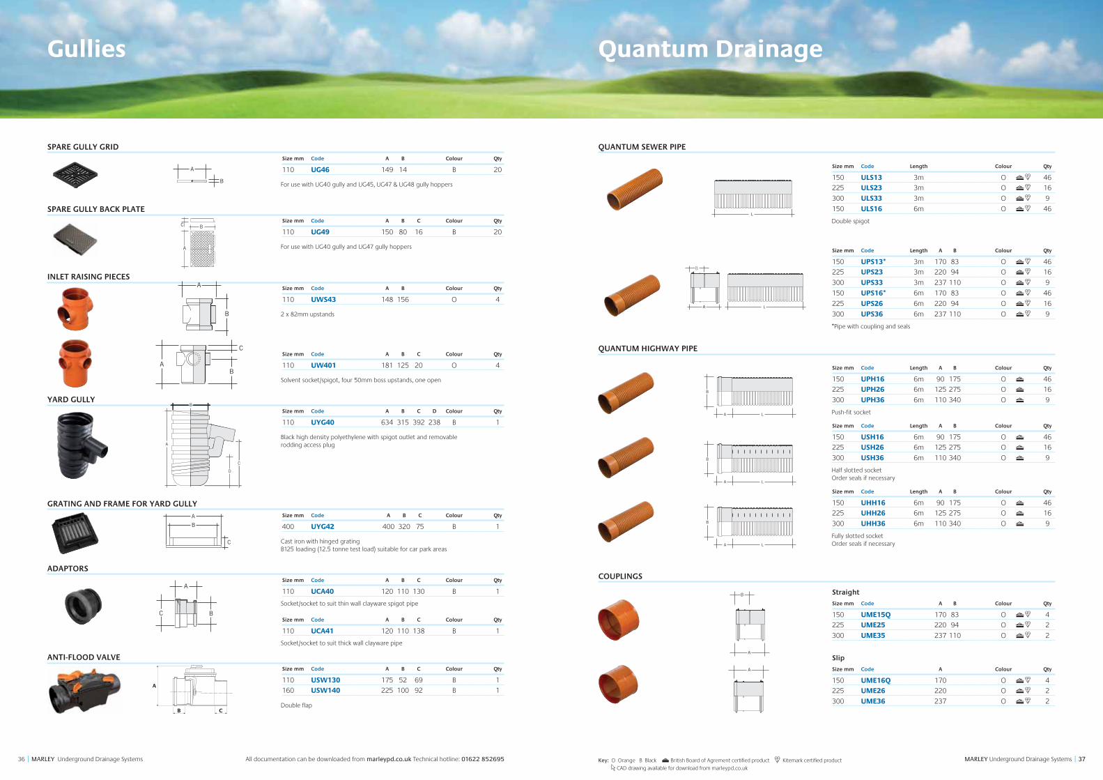
Gullies
SPARE GULLY GRIDSize mm Code A B Colour Qty
110 UG46 149 14 B 20
For use with UG40 gully and UG45, UG47 & UG48 gully hoppers
SPARE GULLY BACK PLATESize mm Code A B C Colour Qty
110 UG49 150 80 16 B 20
For use with UG40 gully and UG47 gully hoppers
INLET RAISING PIECESSize mm Code A B Colour Qty
110 UWS43 148 156 O 4
2 x 82mm upstands
Size mm Code A B C Colour Qty
110 UW401 181 125 20 O 4
Solvent socket/spigot, four 50mm boss upstands, one open
YARD GULLYSize mm Code A B C D Colour Qty
110 UYG40 634 315 392 238 B 1
Black high density polyethylene with spigot outlet and removable rodding access plug
GRATING AND FRAME FOR YARD GULLYSize mm Code A B C Colour Qty
400 UYG42 400 320 75 B 1
Cast iron with hinged grating B125 loading (12.5 tonne test load) suitable for car park areas
ADAPTORSSize mm Code A B C Colour Qty
110 UCA40 120 110 130 B 1
Socket/socket to suit thin wall clayware spigot pipe
Size mm Code A B C Colour Qty
110 UCA41 120 110 138 B 1
Socket/socket to suit thick wall clayware pipe
ANTI-FLOOD VALVESize mm Code A B C Colour Qty
110 USW130 175 52 69 B 1
160 USW140 225 100 92 B 1
Double flap
B
A
C
BA
C
A
D
B
C
A
B
C
A
D
B
C
A
B
C
A
B
BA
C
BA
A
B
B
A
B
A
C
A
BC
B
A
C
B
A
C
A
C B
A
B C
Key: O Orange B Black British Board of Agrement certified product Kitemark certified product
CAD drawing available for download from marleypd.co.uk
Quantum Drainage
QUANTUM SEWER PIPE
Size mm Code Length Colour Qty
150 ULS13 3m O 46
225 ULS23 3m O 16
300 ULS33 3m O 9
150 ULS16 6m O 46
Double spigot
Size mm Code Length A B Colour Qty
150 UPS13* 3m 170 83 O 46
225 UPS23 3m 220 94 O 16
300 UPS33 3m 237 110 O 9
150 UPS16* 6m 170 83 O 46
225 UPS26 6m 220 94 O 16
300 UPS36 6m 237 110 O 9
*Pipe with coupling and seals
QUANTUM HIGHWAY PIPE
Size mm Code Length A B Colour Qty
150 UPH16 6m 90 175 O 46
225 UPH26 6m 125 275 O 16
300 UPH36 6m 110 340 O 9
Push-fit socket
Size mm Code Length A B Colour Qty
150 USH16 6m 90 175 O 46
225 USH26 6m 125 275 O 16
300 USH36 6m 110 340 O 9
Half slotted socket Order seals if necessary
Size mm Code Length A B Colour Qty
150 UHH16 6m 90 175 O 46
225 UHH26 6m 125 275 O 16
300 UHH36 6m 110 340 O 9
Fully slotted socket Order seals if necessary
COUPLINGS
Straight
Size mm Code A B Colour Qty
150 UME15Q 170 83 O 4
225 UME25 220 94 O 2
300 UME35 237 110 O 2
Slip
Size mm Code A Colour Qty
150 UME16Q 170 O 4
225 UME26 220 O 2
300 UME36 237 O 2
B
A L
B
A L
B
L
LA
B
A L
B
A L
B
L
B
L
B
A L
A
B
B
A L
B
A L
B
L
B
L
B
A L
A
B
B
A L
B
A L
B
L
B
L
B
A L
A
B
A
B
A
A
A
C B
A
A
B
A
A
A
C B
A
B
A L
B
A L
B
L
B
L
B
A L
A
B
393938 MARLEY Underground Drainage Systems || MARLEY Underground Drainage Systems All documentation can be downloaded from marleypd.co.uk Technical hotline: 01622 852695
Quantum Drainage
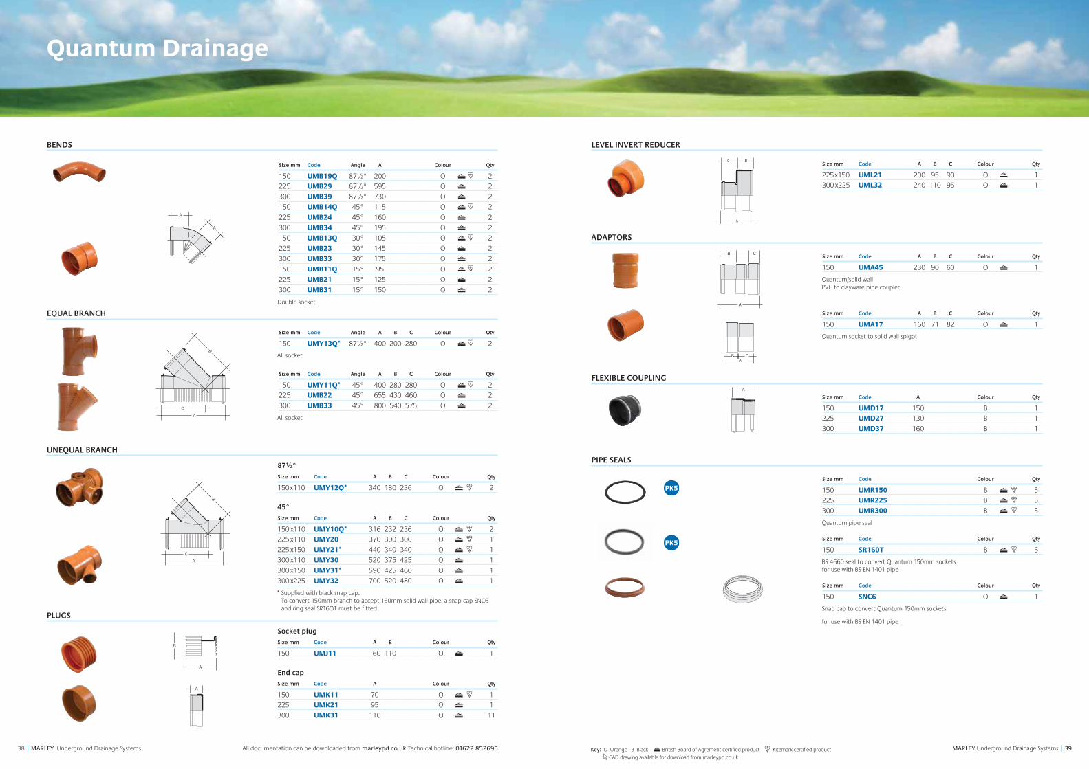
BENDS
Size mm Code Angle A Colour Qty
150 UMB19Q 87½° 200 O 2
225 UMB29 87½° 595 O 2
300 UMB39 87½° 730 O 2
150 UMB14Q 45° 115 O 2
225 UMB24 45° 160 O 2
300 UMB34 45° 195 O 2
150 UMB13Q 30° 105 O 2
225 UMB23 30° 145 O 2
300 UMB33 30° 175 O 2
150 UMB11Q 15° 95 O 2
225 UMB21 15° 125 O 2
300 UMB31 15° 150 O 2
Double socket
EQUAL BRANCH
Size mm Code Angle A B C Colour Qty
150 UMY13Q* 87½° 400 200 280 O 2
All socket
Size mm Code Angle A B C Colour Qty
150 UMY11Q* 45° 400 280 280 O 2
225 UMB22 45° 655 430 460 O 2
300 UMB33 45° 800 540 575 O 2
All socket
UNEQUAL BRANCH
87½°
Size mm Code A B C Colour Qty
150x110 UMY12Q* 340 180 236 O 2
45°
Size mm Code A B C Colour Qty
150 x110 UMY10Q* 316 232 236 O 2
225 x110 UMY20 370 300 300 O 1
225 x150 UMY21* 440 340 340 O 1
300 x110 UMY30 520 375 425 O 1
300 x150 UMY31* 590 425 460 O 1
300 x225 UMY32 700 520 480 O 1
* Supplied with black snap cap. To convert 150mm branch to accept 160mm solid wall pipe, a snap cap SNC6 and ring seal SR16OT must be fitted.
PLUGS
Socket plug
Size mm Code A B Colour Qty
150 UMJ11 160 110 O 1
End cap
Size mm Code A Colour Qty
150 UMK11 70 O 1
225 UMK21 95 O 1
300 UMK31 110 O 11
A
A
A
B
C
A
C
B
B
A
A
A
A
B
C
A
C
B
B
A
Key: O Orange B Black British Board of Agrement certified product Kitemark certified product
CAD drawing available for download from marleypd.co.uk
A
A
A
B
C
A
C
B
B
A
A
A
A
B
C
A
C
B
B
A
A
B
A
A
A
C B
A
LEVEL INVERT REDUCER
Size mm Code A B C Colour Qty
225x150 UML21 200 95 90 O 1
300 x225 UML32 240 110 95 O 1
ADAPTORS
Size mm Code A B C Colour Qty
150 UMA45 230 90 60 O 1
Quantum/solid wall PVC to clayware pipe coupler
Size mm Code A B C Colour Qty
150 UMA17 160 71 82 O 1
Quantum socket to solid wall spigot
FLEXIBLE COUPLING
Size mm Code A Colour Qty
150 UMD17 150 B 1
225 UMD27 130 B 1
300 UMD37 160 B 1
PIPE SEALS
Size mm Code Colour Qty
150 UMR150 B 5
225 UMR225 B 5
300 UMR300 B 5
Quantum pipe seal
Size mm Code Colour Qty
150 SR160T B 5
BS 4660 seal to convert Quantum 150mm sockets for use with BS EN 1401 pipe
Size mm Code Colour Qty
150 SNC6 O 1
Snap cap to convert Quantum 150mm sockets
for use with BS EN 1401 pipe
A
B
A
A
A
C B
A
D
C
BA
A
B C
ACB
B
A
C
D
D
C
BA
A
B C
ACB
B
A
C
D
A
A
A
C B
A
414140 MARLEY Underground Drainage Systems || MARLEY Underground Drainage Systems All documentation can be downloaded from marleypd.co.uk Technical hotline: 01622 852695
Quantum Drainage
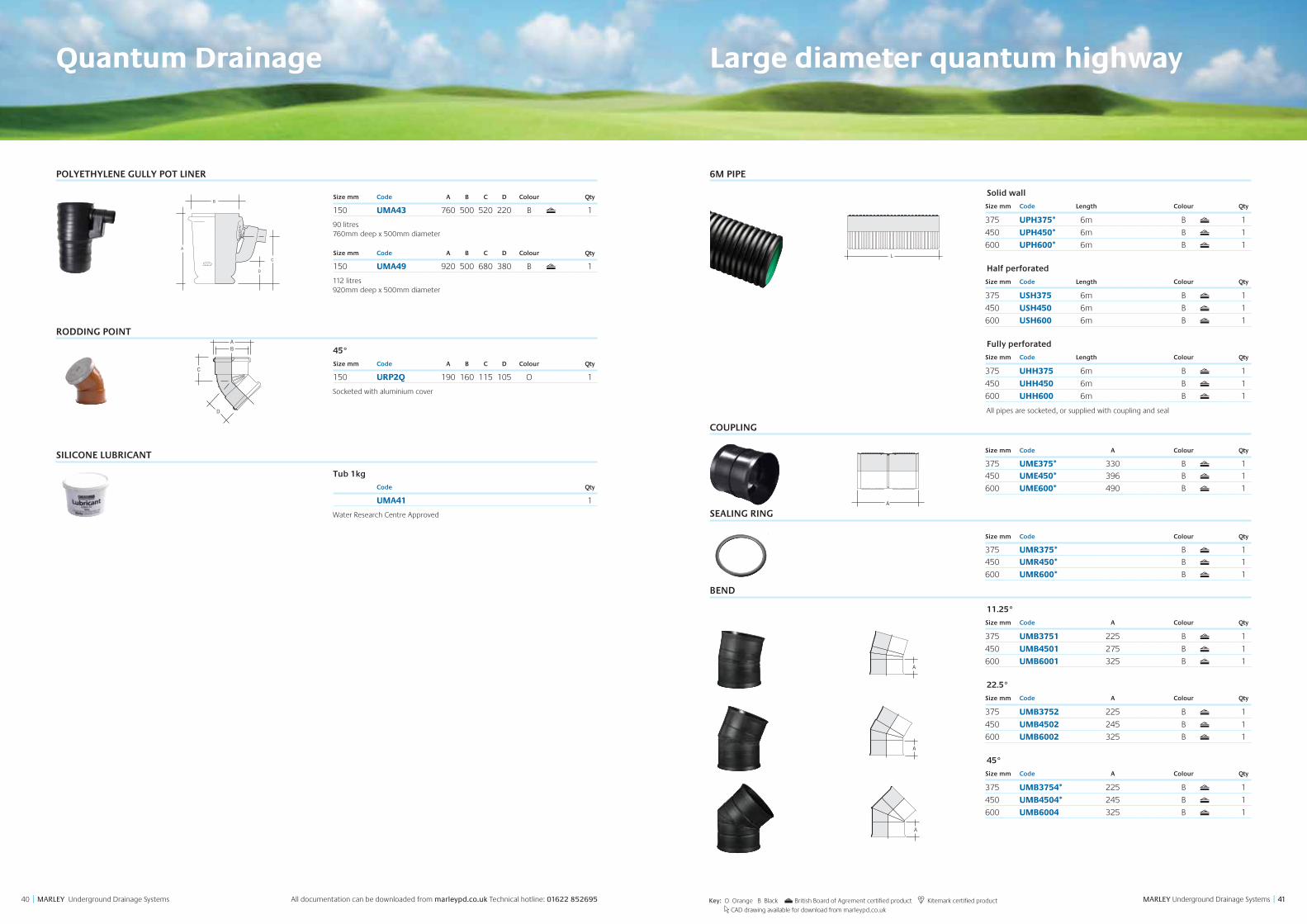
POLYETHYLENE GULLY POT LINER
Size mm Code A B C D Colour Qty
150 UMA43 760 500 520 220 B 1
90 litres 760mm deep x 500mm diameter
Size mm Code A B C D Colour Qty
150 UMA49 920 500 680 380 B 1
112 litres 920mm deep x 500mm diameter
RODDING POINT
45°
Size mm Code A B C D Colour Qty
150 URP2Q 190 160 115 105 O 1
Socketed with aluminium cover
SILICONE LUBRICANT
Tub 1kg
Code Qty
UMA41 1
Water Research Centre Approved
D
C
BA
A
B C
ACB
B
A
C
D
D
C
BA
A
B C
ACB
B
A
C
D
Key: O Orange B Black British Board of Agrement certified product Kitemark certified product
CAD drawing available for download from marleypd.co.uk
Large diameter quantum highway
6M PIPE
Solid wall
Size mm Code Length Colour Qty
375 UPH375* 6m B 1
450 UPH450* 6m B 1
600 UPH600* 6m B 1
Half perforated
Size mm Code Length Colour Qty
375 USH375 6m B 1
450 USH450 6m B 1
600 USH600 6m B 1
Fully perforated
Size mm Code Length Colour Qty
375 UHH375 6m B 1
450 UHH450 6m B 1
600 UHH600 6m B 1
All pipes are socketed, or supplied with coupling and seal
COUPLING
Size mm Code A Colour Qty
375 UME375* 330 B 1
450 UME450* 396 B 1
600 UME600* 490 B 1
SEALING RING
Size mm Code Colour Qty
375 UMR375* B 1
450 UMR450* B 1
600 UMR600* B 1
BEND
11.25°
Size mm Code A Colour Qty
375 UMB3751 225 B 1
450 UMB4501 275 B 1
600 UMB6001 325 B 1
22.5°
Size mm Code A Colour Qty
375 UMB3752 225 B 1
450 UMB4502 245 B 1
600 UMB6002 325 B 1
45°
Size mm Code A Colour Qty
375 UMB3754* 225 B 1
450 UMB4504* 245 B 1
600 UMB6004 325 B 1
B
A L
B
A L
B
L
B
L
B
A L
A
B
A
A A A AB
A A A AB
A A A AB
434342 MARLEY Underground Drainage Systems || MARLEY Underground Drainage Systems All documentation can be downloaded from marleypd.co.uk Technical hotline: 01622 852695 Key: B Black British Board of Agrement certified product Kitemark certified product
CAD drawing available for download from marleypd.co.uk
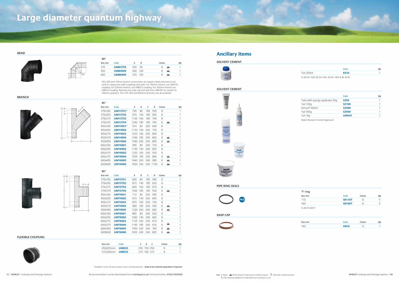
BEND
90°
Size mm Code A B Colour Qty
375 UMB3759 250 90 B 1
450 UMB4509 290 100 B 1
600 UMB6009 370 100 B 1
160, 250 and 315mm branch connections are spigot ended and need to be used in conjunction with couplings and seals. For 160mm branch, use UME15C coupling. For 250mm branch, use UMD23 coupling. For 300mm branch use UMD33 coupling. Remove one snap cap and seal from UME15C to convert to 150mm quantum. The 375, 450 and 600mm branches are all socketed.
BRANCH
45°
Size mm Code A B C D Colour Qty
375x160 UMY3751* 795 80 185 595 B 1
375x250 UMY3752 970 140 185 695 B 1
375x315 UMY3753 1100 160 185 795 B 1
375x375 UMY3754 1240 185 185 760 B 1
450x160 UMY4501* 970 80 200 640 B 1
450x250 UMY4502 1130 140 200 735 B 1
450x315 UMY4503 1230 160 200 840 B 1
450X375 UMY4504 1390 185 200 800 B 1
450X450 UMY4505 1490 200 200 895 B 1
600x160 UMY6001 995 80 240 730 B 1
600x250 UMY6002 1190 140 240 825 B 1
600x315 UMY6003 1320 160 240 930 B 1
600x375 UMY6004 1505 185 240 890 B 1
600x450 UMY6005 1640 200 240 985 B 1
600X600 UMY6006 1900 240 240 1190 B 1
90°
Size mm Code A B C D Colour Qty
375x160 UMT3751 665 80 185 585 B 1
375x250 UMT3752 815 140 185 620 B 1
375x315 UMT3753 840 160 185 675 B 1
375X375 UMT3754 1000 185 185 500 B 1
450x160 UMT4501 710 80 200 580 B 1
450x250 UMT4502 815 140 200 665 B 1
450x315 UMT4503 870 160 200 720 B 1
450X375 UMT4504 980 185 200 540 B 1
450X450 UMT4505 1320 200 200 660 B 1
600x160 UMT6001 865 80 240 620 B 1
600x250 UMT6002 1060 140 240 665 B 1
600x315 UMT6003 1125 160 240 810 B 1
600X375 UMT6004 1190 185 240 630 B 1600X450 UMT6005 1450 200 240 760 B 1600X600 UMT6006 1650 240 240 825 B 1
FLEXIBLE COUPLING
Size mm Code A B C Colour Qty
250/225mm UMD23 250 150 250 B 1
315/300mm UMD33 315 190 315 B 1
A A A AB
A
D
CB
A
D
C
B
* Available in stock. All other products have a 28 day lead time. Seals to be ordered separately if required.
Large diameter quantum highway
Ancillary Items
SOLVENT CEMENT
Code Qty
Tub 250ml KS10 1
To BS EN 1329, BS EN 1401, BS EN 1455 & BS 4576
SOLVENT CEMENT
Code Qty
Tube with sponge applicator 50g SZ50 1
Tub 100g SZ100 1
Aerosol* 400ml SZ400 1
Tub 500g SZ500 1
Tub 1kg UMA41 1
Water Research Centre Approved
PIPE RING SEALS
‘T’ ring
Size mm Code Colour Qty
110 SR110T B 5
160 SR160T B 5
To BS EN 681/1
SNAP CAP
Size mm Code Colour Qty
160 SNC6 O 1

marleypd.co.uk For general enquiries and details of your nearest stockist please call the customer services department: Tel: 01622 852585email: [email protected]
For Technical advice please call 01622 852695
Head OfficeLenham, Maidstone Kent ME17 2DE Tel: 01622 858888 Fax: 01622 858725
ScotlandBirkenshaw Industrial Estate Uddingston, Glasgow G71 5PA Tel: 01698 815231 Fax: 01698 810307
Export DivisionLenham, Maidstone Kent ME17 2DE England Tel: +44 (0)1622 858888 Fax: +44 (0)1622 850778
July 2015