3. plumbing and drainage part 1
TRANSCRIPT
3. Plumbing and Drainage Part 13.2 Sanitation and drainage systems
Training Course on Building Services Engineering
Ir Dr. Sam C. M. HuiDepartment of Mechanical Engineering
The University of Hong KongE-mail: [email protected]
Mar 2021
Contents
• Sanitary drainage
• Stormwater drainage
• Drainage below ground
• Drainage defects
Sanitary drainage
• Design of drainage systems
• Sanitary fitments
• Above ground drainage
• Below ground drainage (+ sewage disposal)
• Aim: To remove waste, foul & surface water
• Waste water (廢水) = basins, sinks, baths, showers
• Soil or foul water (髒水) = from toilets or W.C.
• Surface water (地面水) = rainwater or stormwater
• Systems will last as long as the building!!
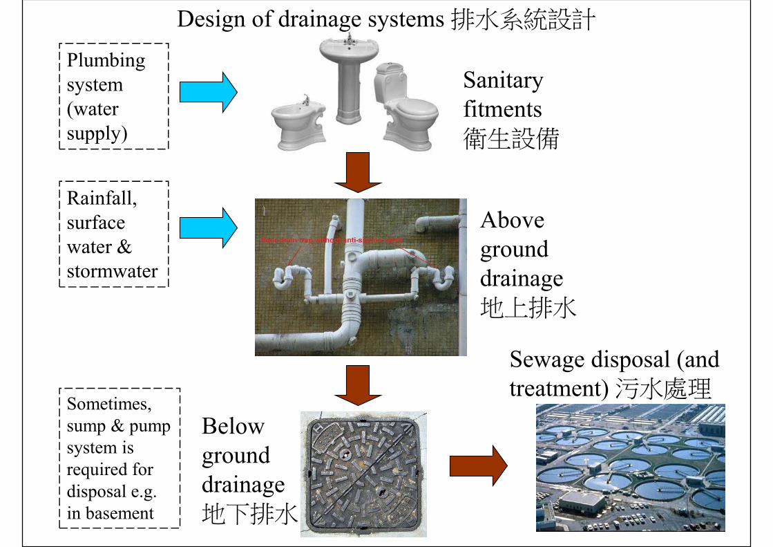
Sanitary fitments衛生設備
Above ground drainage地上排水
Below ground drainage地下排水
Sewage disposal (and treatment) 污水處理
Plumbing system (water supply)
Rainfall, surface water & stormwater
Sometimes, sump & pump system is required for disposal e.g. in basement
Design of drainage systems 排水系統設計
Sanitary drainage
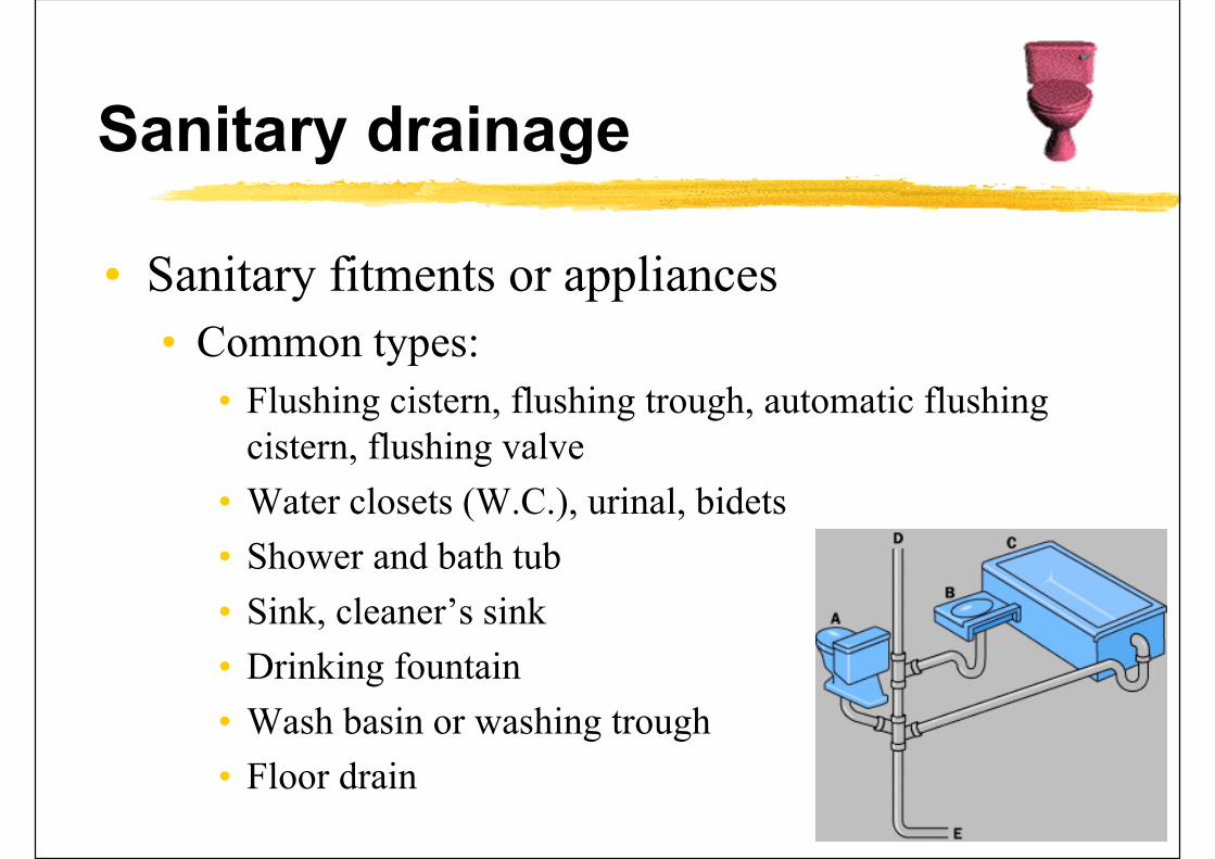
• Sanitary fitments or appliances
• Common types:
• Flushing cistern, flushing trough, automatic flushing cistern, flushing valve
• Water closets (W.C.), urinal, bidets
• Shower and bath tub
• Sink, cleaner’s sink
• Drinking fountain
• Wash basin or washing trough
• Floor drain

Sanitary drainage
• Types of drainage pipes• Waste pipe (WP): e.g. connected to basins & baths
• Soil pipe (SP): e.g. connected to W.C.
• Ventilating/Vent pipe (VP)
• Rain water pipe (RWP)
• Anti-siphonage pipe: preserve water seals of traps
• Air-conditioning condensation drainage pipe
• Use of traps (control foul gas or odour)• U-trap: a U-shaped running trap
• P-trap and S-trap
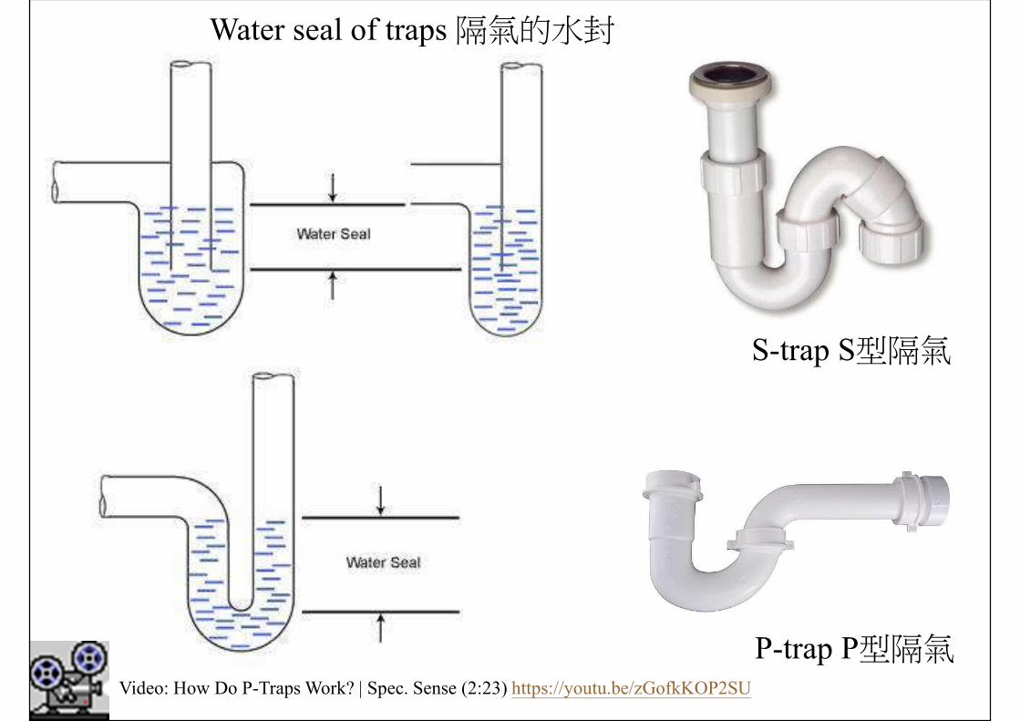
Water seal of traps 隔氣的水封
S-trap S型隔氣
P-trap P型隔氣Video: How Do P-Traps Work? | Spec. Sense (2:23) https://youtu.be/zGofkKOP2SU
Sanitary drainage
• Types of sanitary drainage stack systems• Single stack system
• Collar boss system
• Modified single stack system
• Fully ventilated one-pipe system
• Two-pipe system
• Selection depends on situations, costs & local design practices
• Design considerations: e.g. pipe size, distance
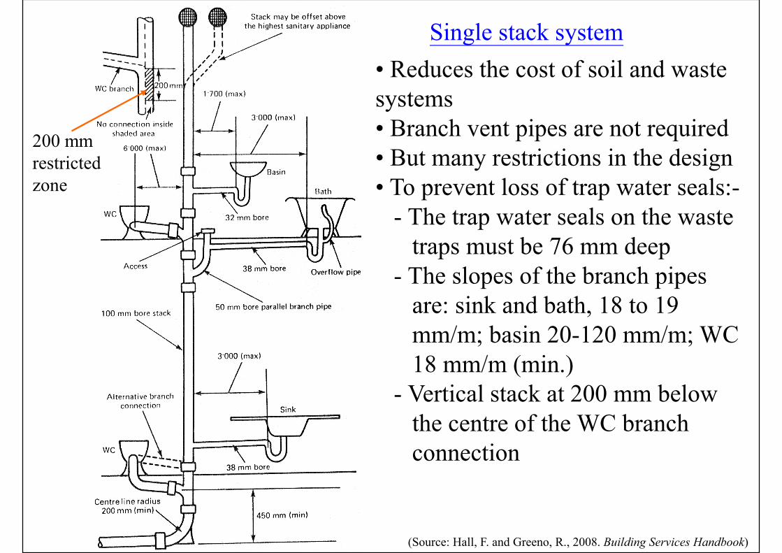
Single stack system
(Source: Hall, F. and Greeno, R., 2008. Building Services Handbook)
• Reduces the cost of soil and waste systems• Branch vent pipes are not required• But many restrictions in the design• To prevent loss of trap water seals:-
- The trap water seals on the waste traps must be 76 mm deep
- The slopes of the branch pipes are: sink and bath, 18 to 19 mm/m; basin 20-120 mm/m; WC 18 mm/m (min.)
- Vertical stack at 200 mm below the centre of the WC branch connection
200 mm restricted zone
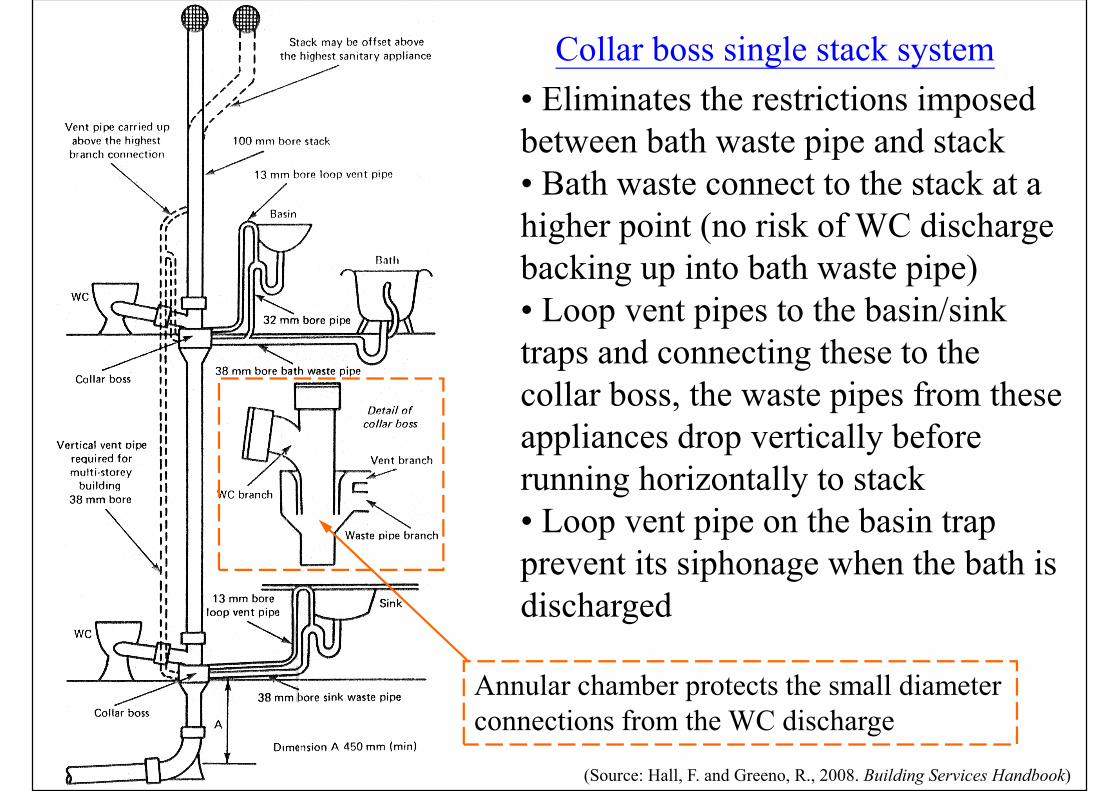
Collar boss single stack system
(Source: Hall, F. and Greeno, R., 2008. Building Services Handbook)
• Eliminates the restrictions imposed between bath waste pipe and stack• Bath waste connect to the stack at a higher point (no risk of WC discharge backing up into bath waste pipe)• Loop vent pipes to the basin/sink traps and connecting these to the collar boss, the waste pipes from these appliances drop vertically before running horizontally to stack • Loop vent pipe on the basin trap prevent its siphonage when the bath is discharged
Annular chamber protects the small diameter connections from the WC discharge
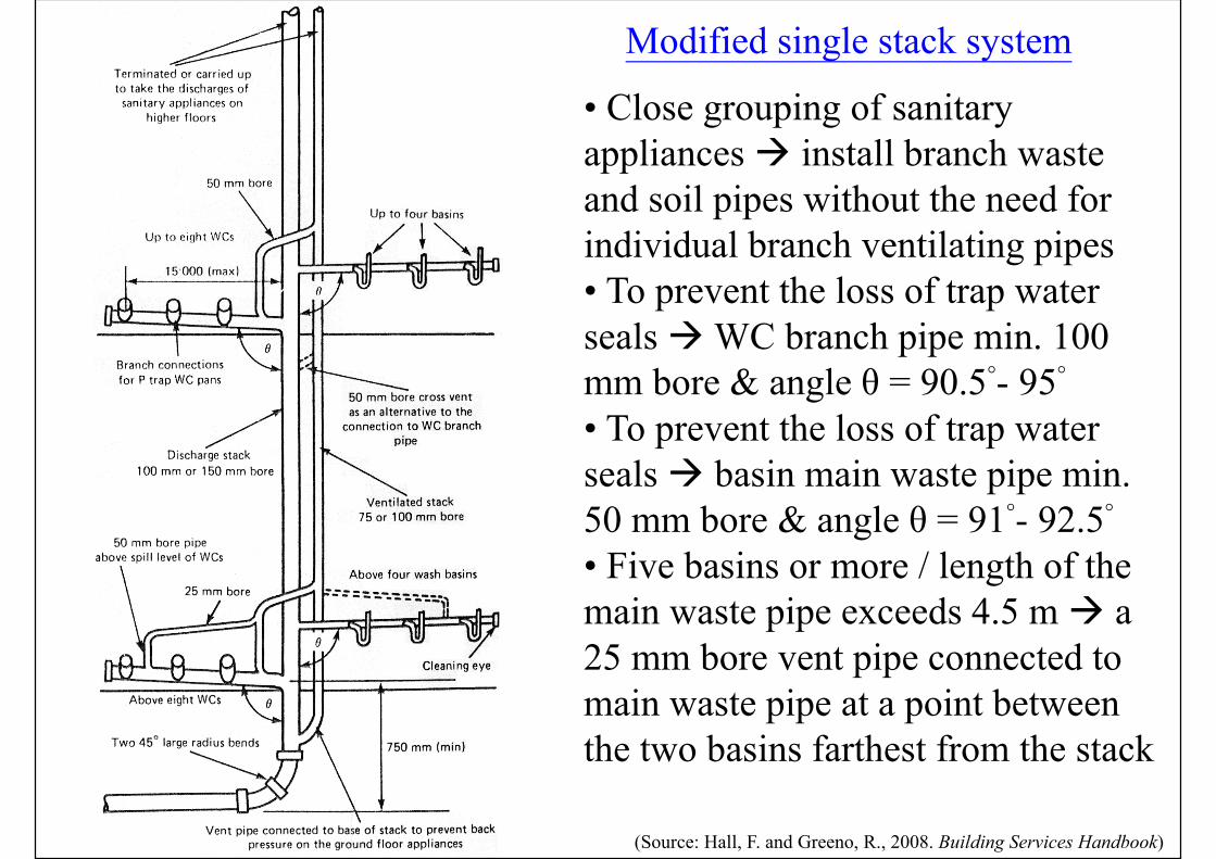
Modified single stack system
(Source: Hall, F. and Greeno, R., 2008. Building Services Handbook)
• Close grouping of sanitary appliances install branch waste and soil pipes without the need for individual branch ventilating pipes• To prevent the loss of trap water seals WC branch pipe min. 100 mm bore & angle θ = 90.5°- 95°• To prevent the loss of trap water seals basin main waste pipe min. 50 mm bore & angle θ = 91°- 92.5°• Five basins or more / length of the main waste pipe exceeds 4.5 m a 25 mm bore vent pipe connected to main waste pipe at a point between the two basins farthest from the stack
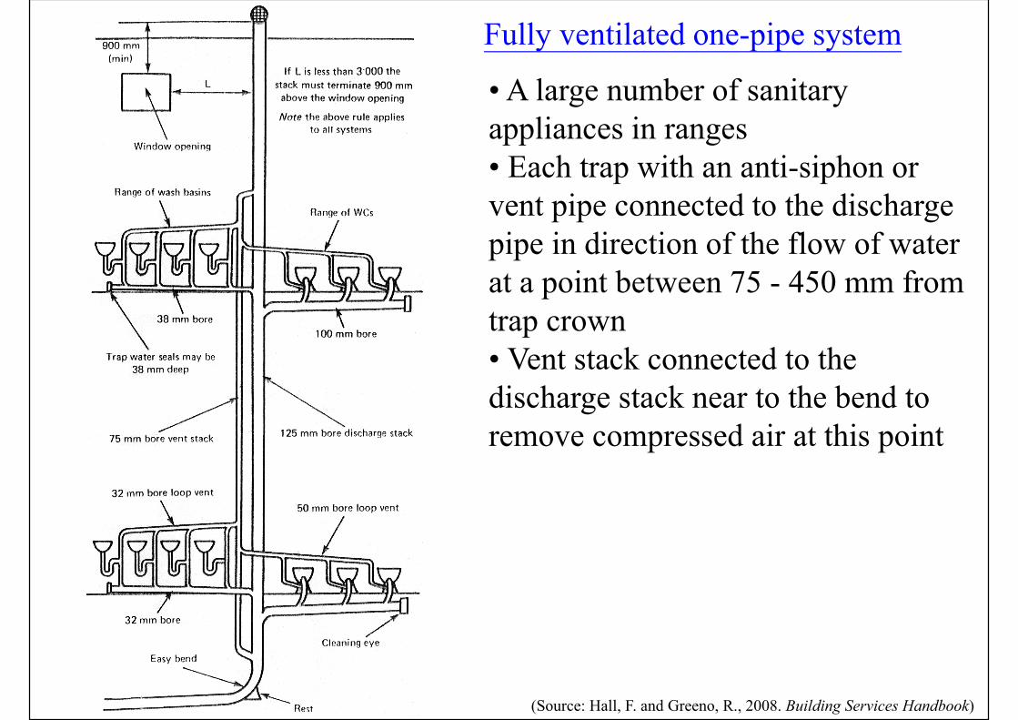
Fully ventilated one-pipe system
(Source: Hall, F. and Greeno, R., 2008. Building Services Handbook)
• A large number of sanitary appliances in ranges• Each trap with an anti-siphon or vent pipe connected to the discharge pipe in direction of the flow of water at a point between 75 - 450 mm from trap crown• Vent stack connected to the discharge stack near to the bend to remove compressed air at this point
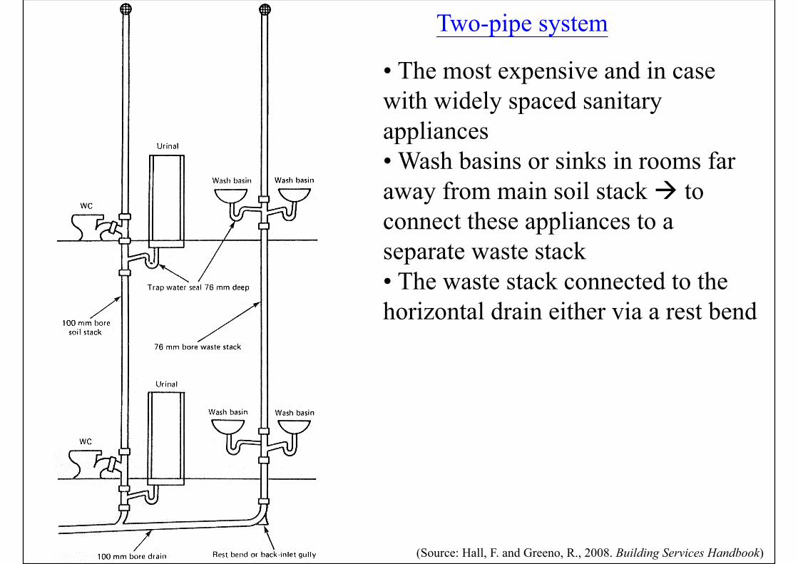
Two-pipe system
(Source: Hall, F. and Greeno, R., 2008. Building Services Handbook)
• The most expensive and in case with widely spaced sanitary appliances• Wash basins or sinks in rooms far away from main soil stack to connect these appliances to a separate waste stack • The waste stack connected to the horizontal drain either via a rest bend
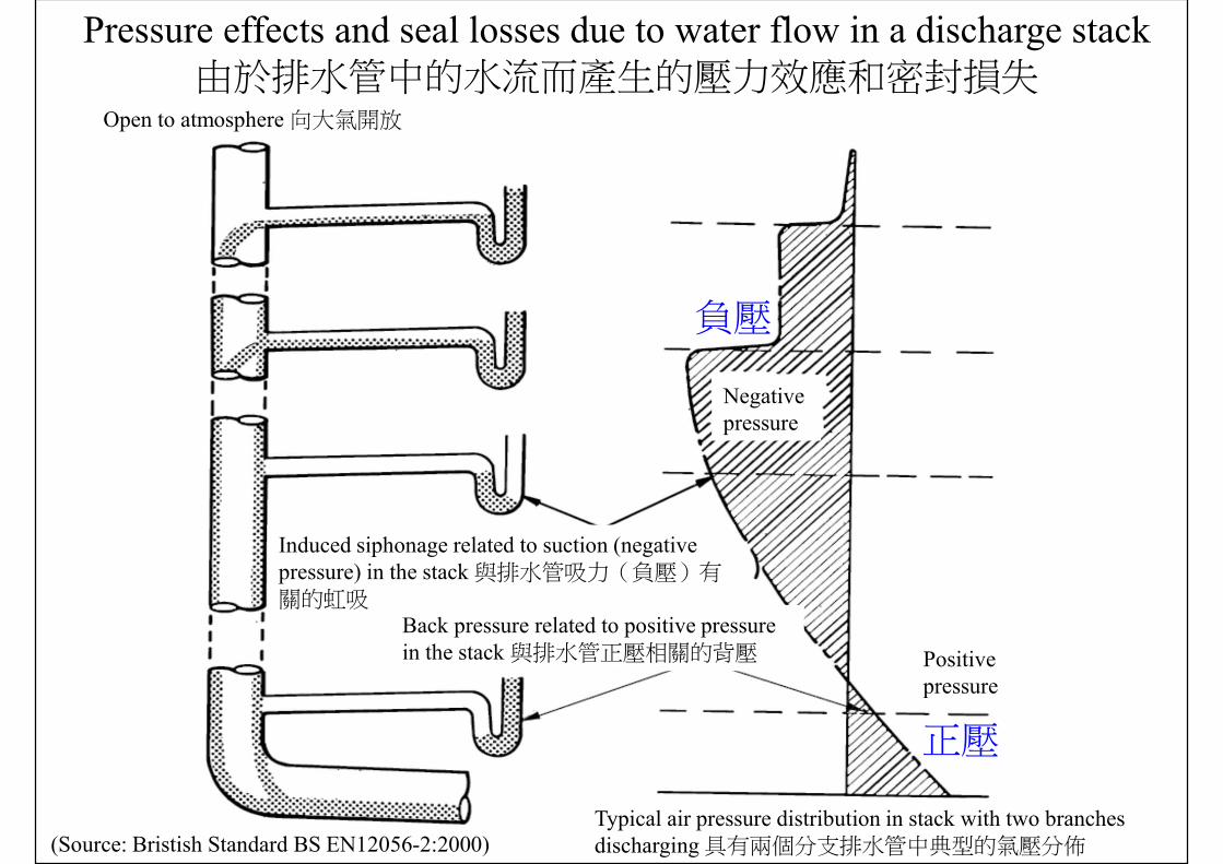
(Source: Bristish Standard BS EN12056-2:2000)
Pressure effects and seal losses due to water flow in a discharge stack由於排水管中的水流而產生的壓力效應和密封損失
Open to atmosphere 向大氣開放
Negative pressure
Induced siphonage related to suction (negative pressure) in the stack 與排水管吸力(負壓)有關的虹吸
Back pressure related to positive pressure in the stack 與排水管正壓相關的背壓 Positive
pressure
Typical air pressure distribution in stack with two branches discharging 具有兩個分支排水管中典型的氣壓分佈
負壓
正壓
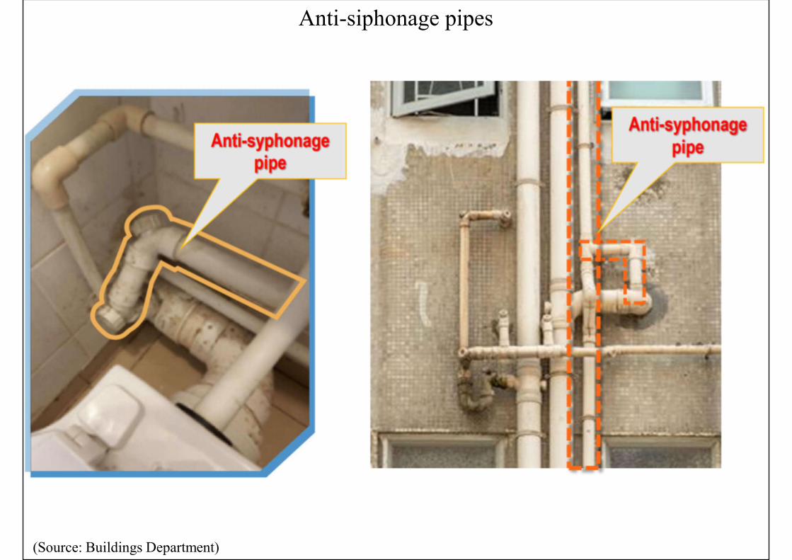
Anti-siphonage pipes
(Source: Buildings Department)
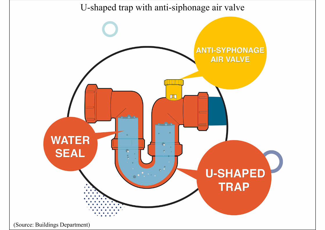
U-shaped trap with anti-siphonage air valve
(Source: Buildings Department)
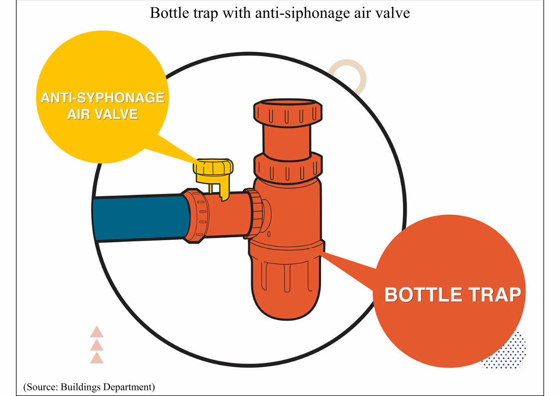
Bottle trap with anti-siphonage air valve
(Source: Buildings Department)
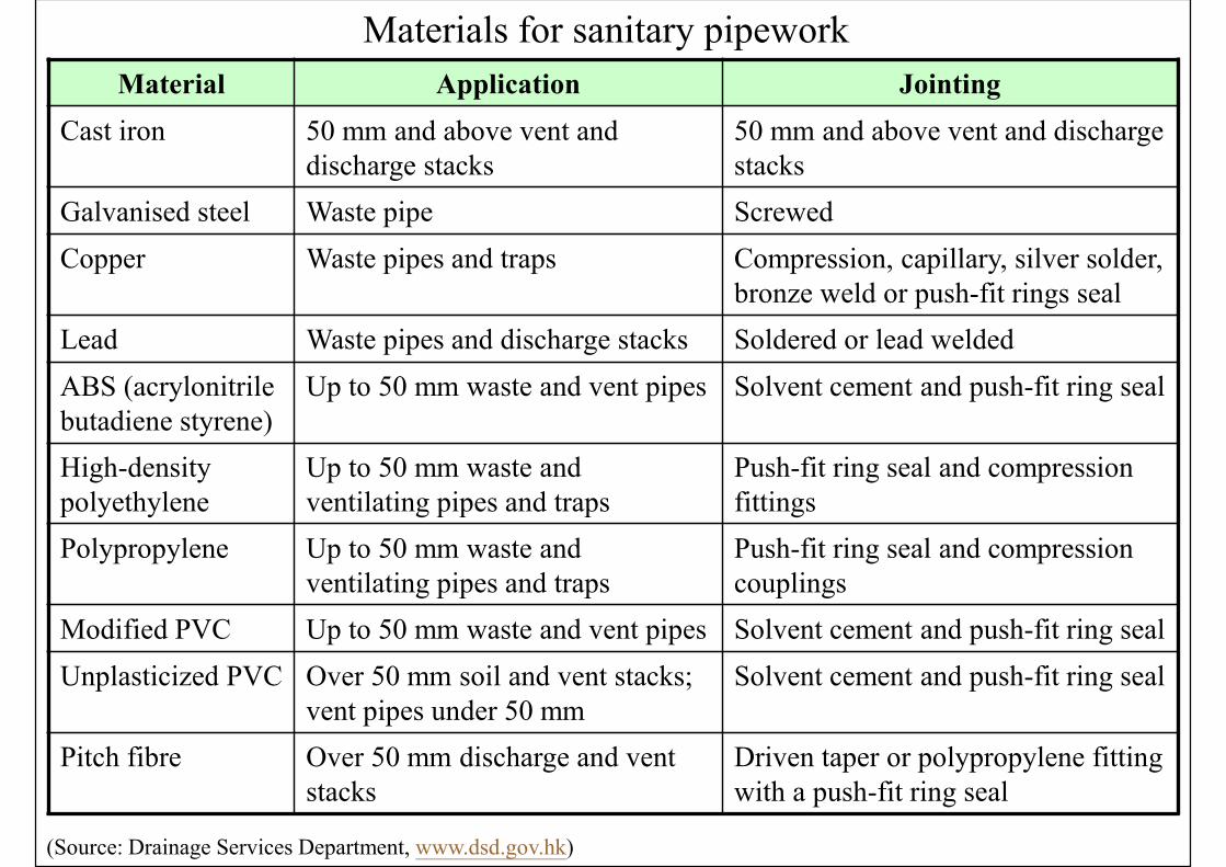
Materials for sanitary pipework
Material Application Jointing
Cast iron 50 mm and above vent and discharge stacks
50 mm and above vent and discharge stacks
Galvanised steel Waste pipe Screwed
Copper Waste pipes and traps Compression, capillary, silver solder, bronze weld or push-fit rings seal
Lead Waste pipes and discharge stacks Soldered or lead welded
ABS (acrylonitrile butadiene styrene)
Up to 50 mm waste and vent pipes Solvent cement and push-fit ring seal
High-density polyethylene
Up to 50 mm waste and ventilating pipes and traps
Push-fit ring seal and compression fittings
Polypropylene Up to 50 mm waste and ventilating pipes and traps
Push-fit ring seal and compression couplings
Modified PVC Up to 50 mm waste and vent pipes Solvent cement and push-fit ring seal
Unplasticized PVC Over 50 mm soil and vent stacks; vent pipes under 50 mm
Solvent cement and push-fit ring seal
Pitch fibre Over 50 mm discharge and vent stacks
Driven taper or polypropylene fitting with a push-fit ring seal
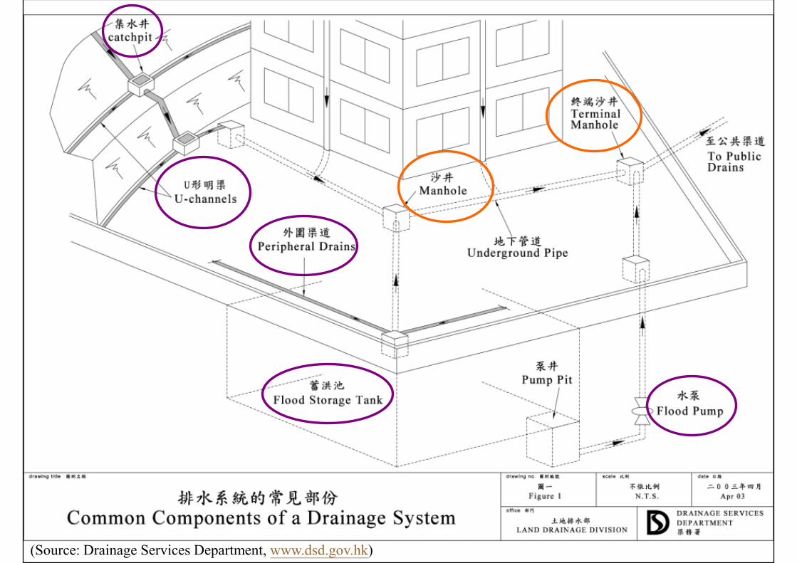
(Source: Drainage Services Department, www.dsd.gov.hk)
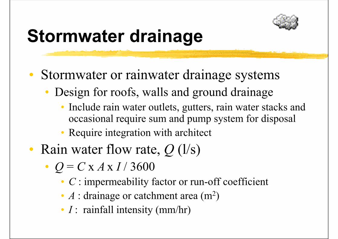
Stormwater drainage
• Stormwater or rainwater drainage systems• Design for roofs, walls and ground drainage
• Include rain water outlets, gutters, rain water stacks and occasional require sum and pump system for disposal
• Require integration with architect
• Rain water flow rate, Q (l/s)• Q = C x A x I / 3600
• C : impermeability factor or run-off coefficient
• A : drainage or catchment area (m2)
• I : rainfall intensity (mm/hr)

Ground impermeability factor
Nature of surface Impermeability factor
Road or pavement 0.90
Roof 0.95
Path 0.75
Parks or gardens 0.25
Woodland 0.20
(Source: Chadderton, D. V., 2007. Building Services Engineering)
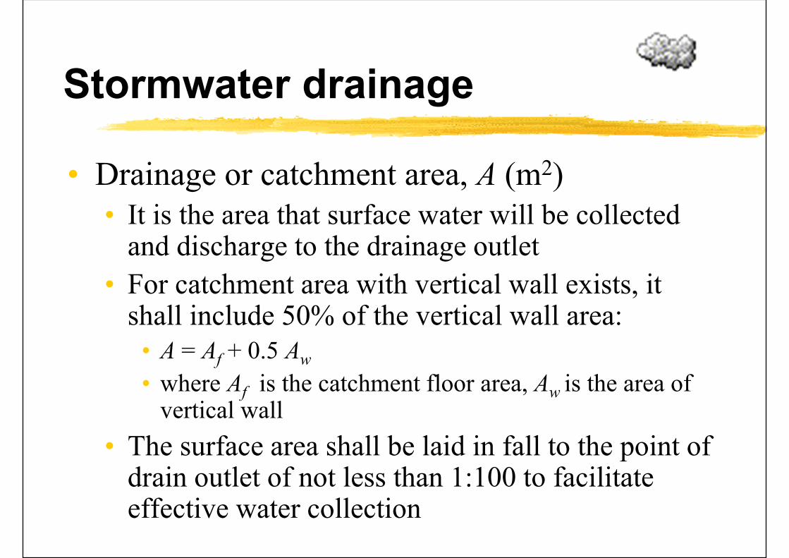
Stormwater drainage
• Drainage or catchment area, A (m2)• It is the area that surface water will be collected
and discharge to the drainage outlet
• For catchment area with vertical wall exists, it shall include 50% of the vertical wall area:
• A = Af + 0.5 Aw
• where Af is the catchment floor area, Aw is the area of vertical wall
• The surface area shall be laid in fall to the point of drain outlet of not less than 1:100 to facilitate effective water collection
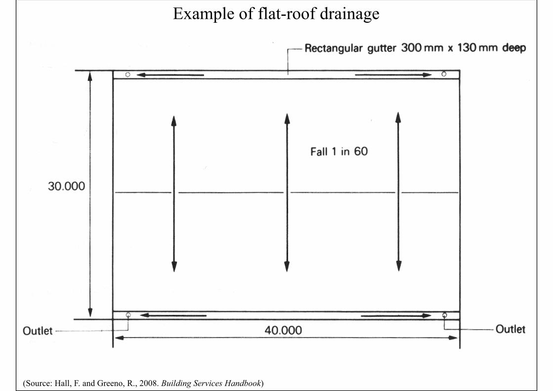
Example of flat-roof drainage
(Source: Hall, F. and Greeno, R., 2008. Building Services Handbook)
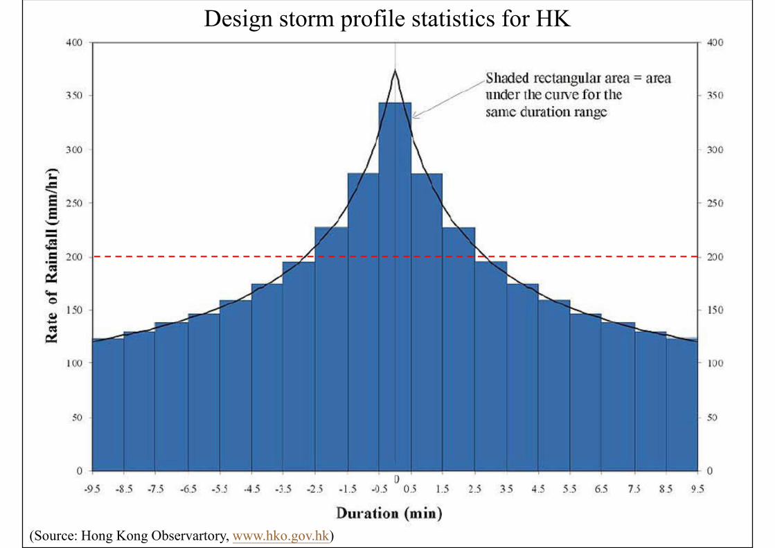
(Source: Hong Kong Observartory, www.hko.gov.hk)
Design storm profile statistics for HK
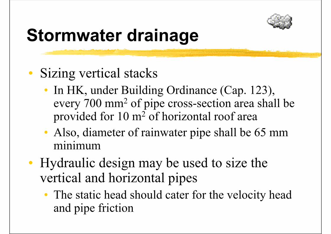
Stormwater drainage
• Sizing vertical stacks• In HK, under Building Ordinance (Cap. 123),
every 700 mm2 of pipe cross-section area shall be provided for 10 m2 of horizontal roof area
• Also, diameter of rainwater pipe shall be 65 mm minimum
• Hydraulic design may be used to size the vertical and horizontal pipes• The static head should cater for the velocity head
and pipe friction
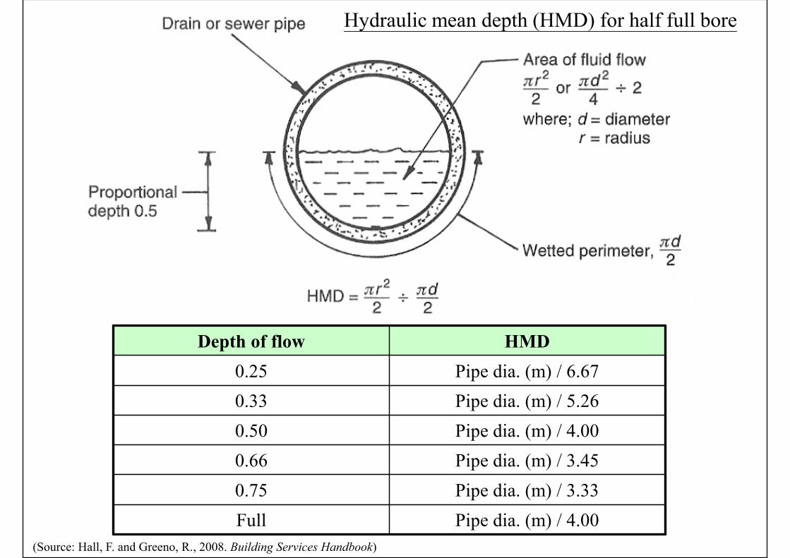
Hydraulic mean depth (HMD) for half full bore
(Source: Hall, F. and Greeno, R., 2008. Building Services Handbook)
Depth of flow HMD
0.25 Pipe dia. (m) / 6.67
0.33 Pipe dia. (m) / 5.26
0.50 Pipe dia. (m) / 4.00
0.66 Pipe dia. (m) / 3.45
0.75 Pipe dia. (m) / 3.33
Full Pipe dia. (m) / 4.00
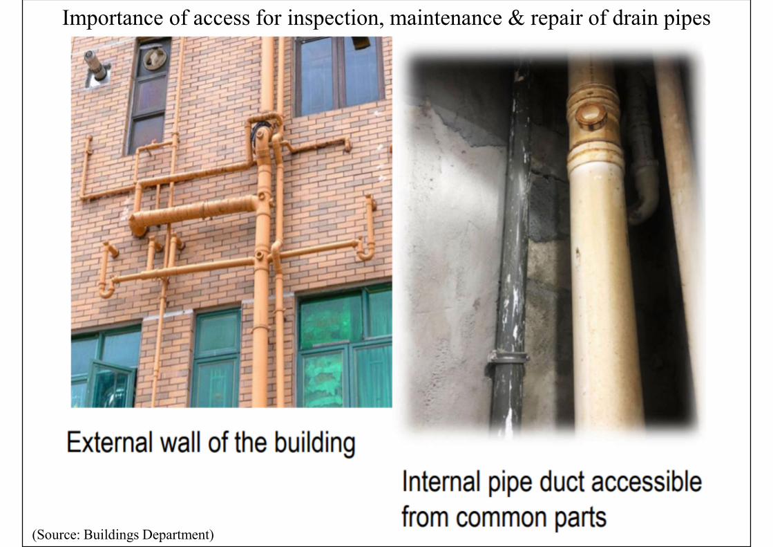
Importance of access for inspection, maintenance & repair of drain pipes
(Source: Buildings Department)
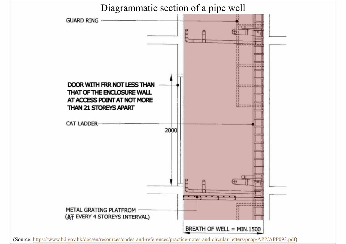
Diagrammatic section of a pipe well
(Source: https://www.bd.gov.hk/doc/en/resources/codes-and-references/practice-notes-and-circular-letters/pnap/APP/APP093.pdf)
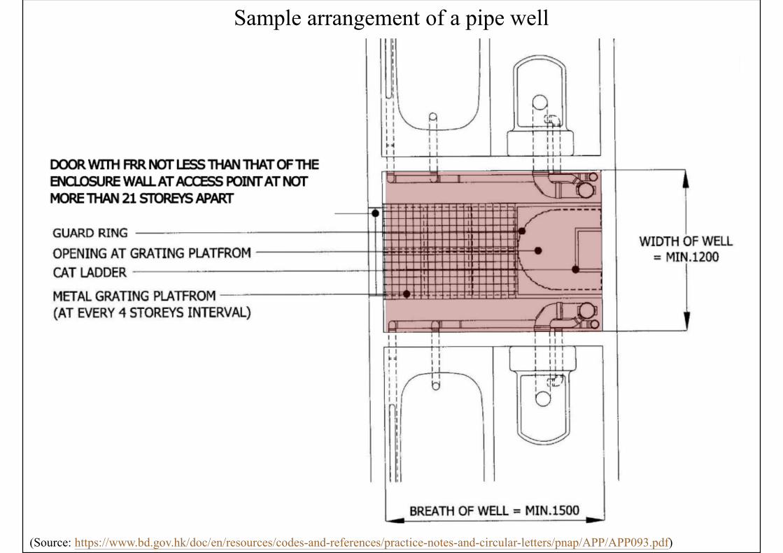
Sample arrangement of a pipe well
(Source: https://www.bd.gov.hk/doc/en/resources/codes-and-references/practice-notes-and-circular-letters/pnap/APP/APP093.pdf)
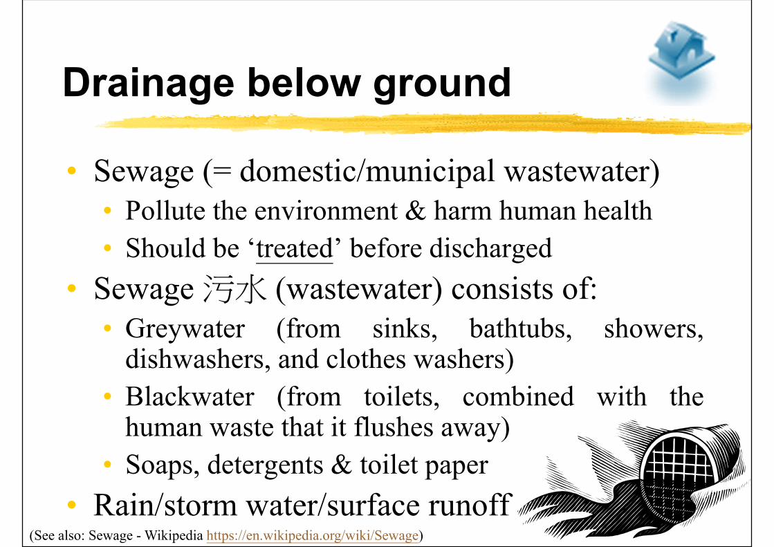
Drainage below ground
• Sewage (= domestic/municipal wastewater)• Pollute the environment & harm human health
• Should be ‘treated’ before discharged
• Sewage污水 (wastewater) consists of:• Greywater (from sinks, bathtubs, showers,
dishwashers, and clothes washers)
• Blackwater (from toilets, combined with thehuman waste that it flushes away)
• Soaps, detergents & toilet paper
• Rain/storm water/surface runoff(See also: Sewage - Wikipedia https://en.wikipedia.org/wiki/Sewage)
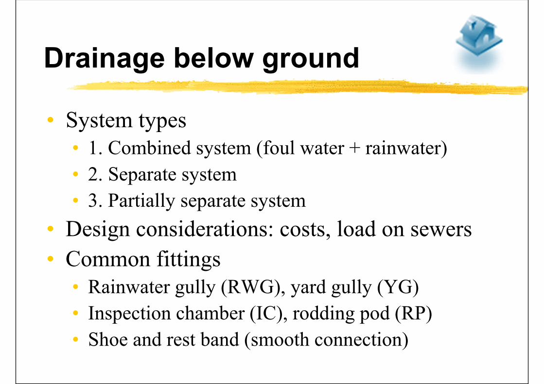
Drainage below ground
• System types• 1. Combined system (foul water + rainwater)
• 2. Separate system
• 3. Partially separate system
• Design considerations: costs, load on sewers
• Common fittings• Rainwater gully (RWG), yard gully (YG)
• Inspection chamber (IC), rodding pod (RP)
• Shoe and rest band (smooth connection)
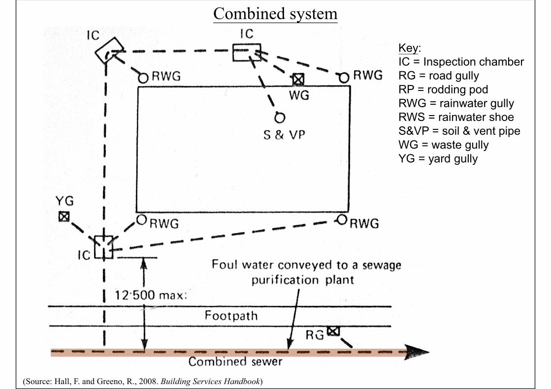
Combined system
(Source: Hall, F. and Greeno, R., 2008. Building Services Handbook)
Key:IC = Inspection chamber RG = road gullyRP = rodding pod RWG = rainwater gullyRWS = rainwater shoeS&VP = soil & vent pipeWG = waste gullyYG = yard gully
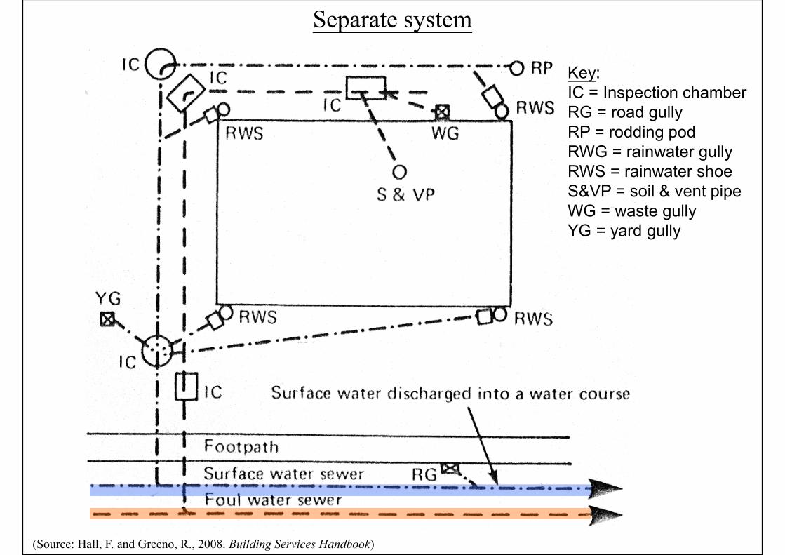
Separate system
(Source: Hall, F. and Greeno, R., 2008. Building Services Handbook)
Key:IC = Inspection chamber RG = road gullyRP = rodding pod RWG = rainwater gullyRWS = rainwater shoeS&VP = soil & vent pipeWG = waste gullyYG = yard gully
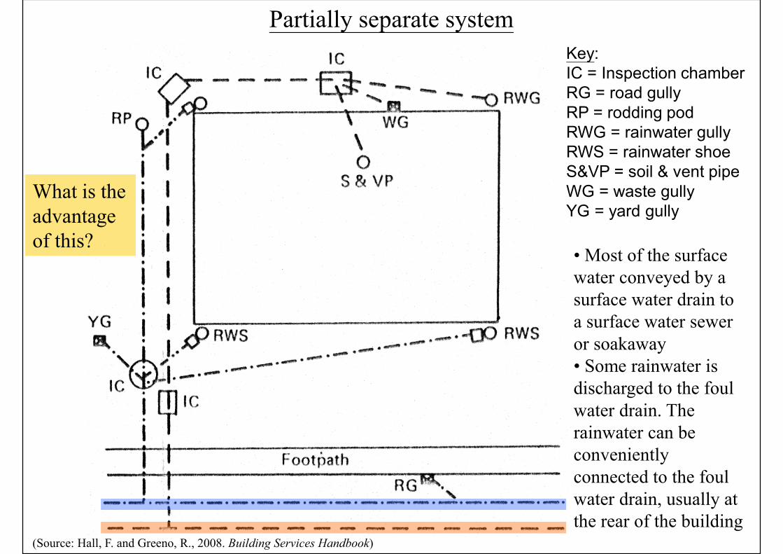
Partially separate system
(Source: Hall, F. and Greeno, R., 2008. Building Services Handbook)
• Most of the surface water conveyed by a surface water drain to a surface water sewer or soakaway • Some rainwater is discharged to the foul water drain. The rainwater can be conveniently connected to the foul water drain, usually at the rear of the building
Key:IC = Inspection chamber RG = road gullyRP = rodding pod RWG = rainwater gullyRWS = rainwater shoeS&VP = soil & vent pipeWG = waste gullyYG = yard gully
What is the advantage of this?
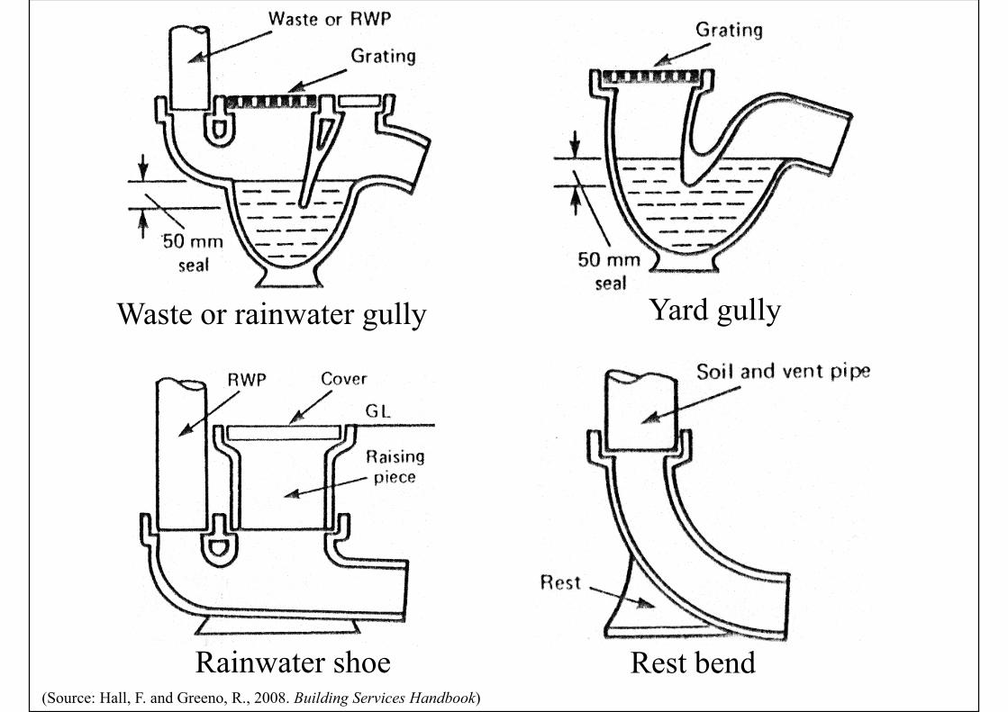
Waste or rainwater gully Yard gully
Rainwater shoe Rest bend(Source: Hall, F. and Greeno, R., 2008. Building Services Handbook)
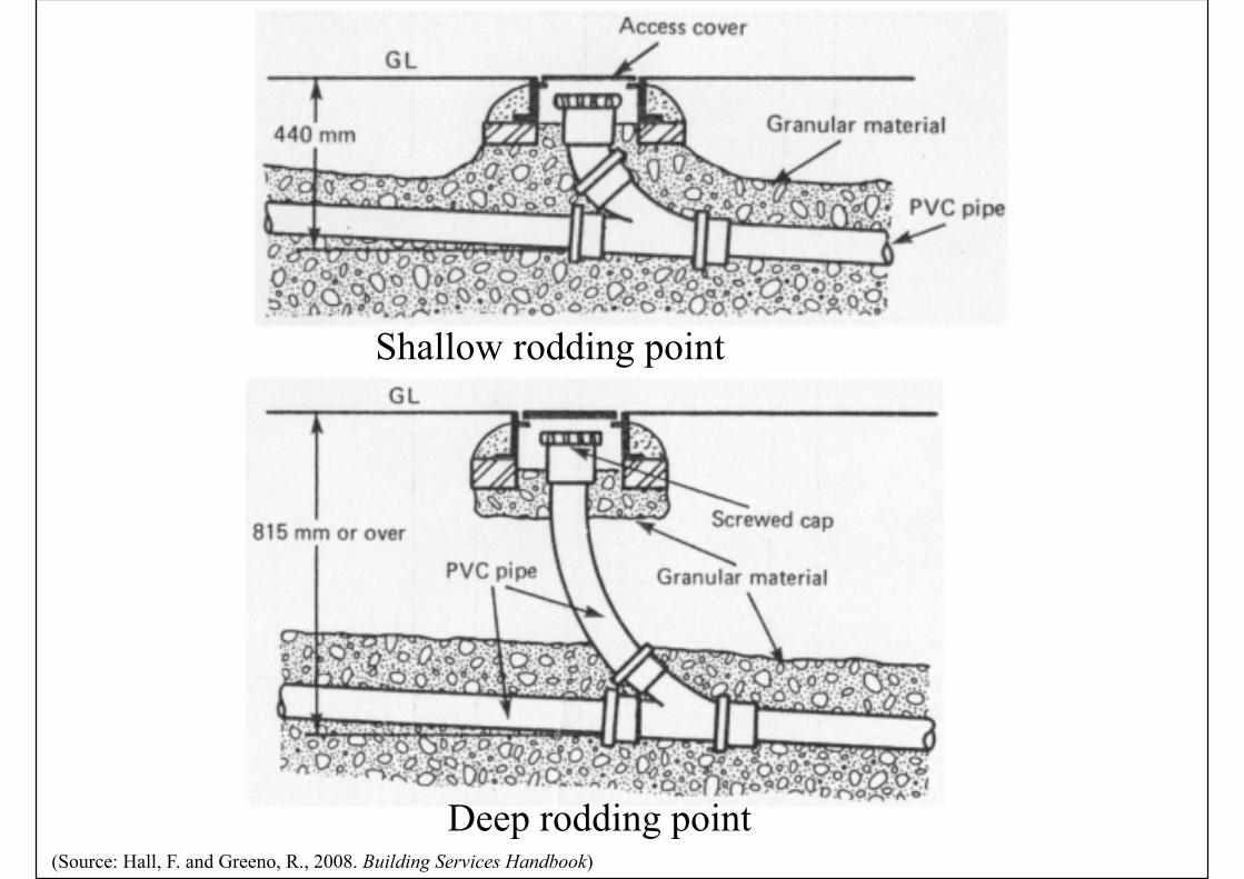
Shallow rodding point
Deep rodding point(Source: Hall, F. and Greeno, R., 2008. Building Services Handbook)
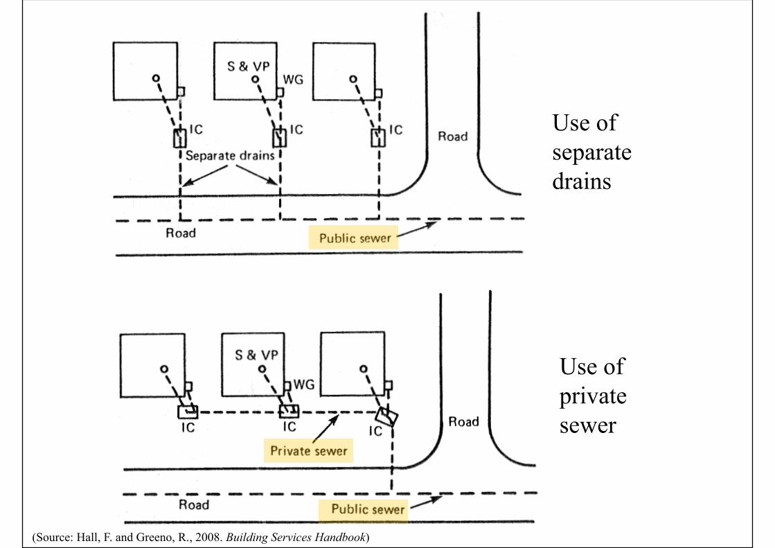
Use of separate drains
Use of private sewer
(Source: Hall, F. and Greeno, R., 2008. Building Services Handbook)
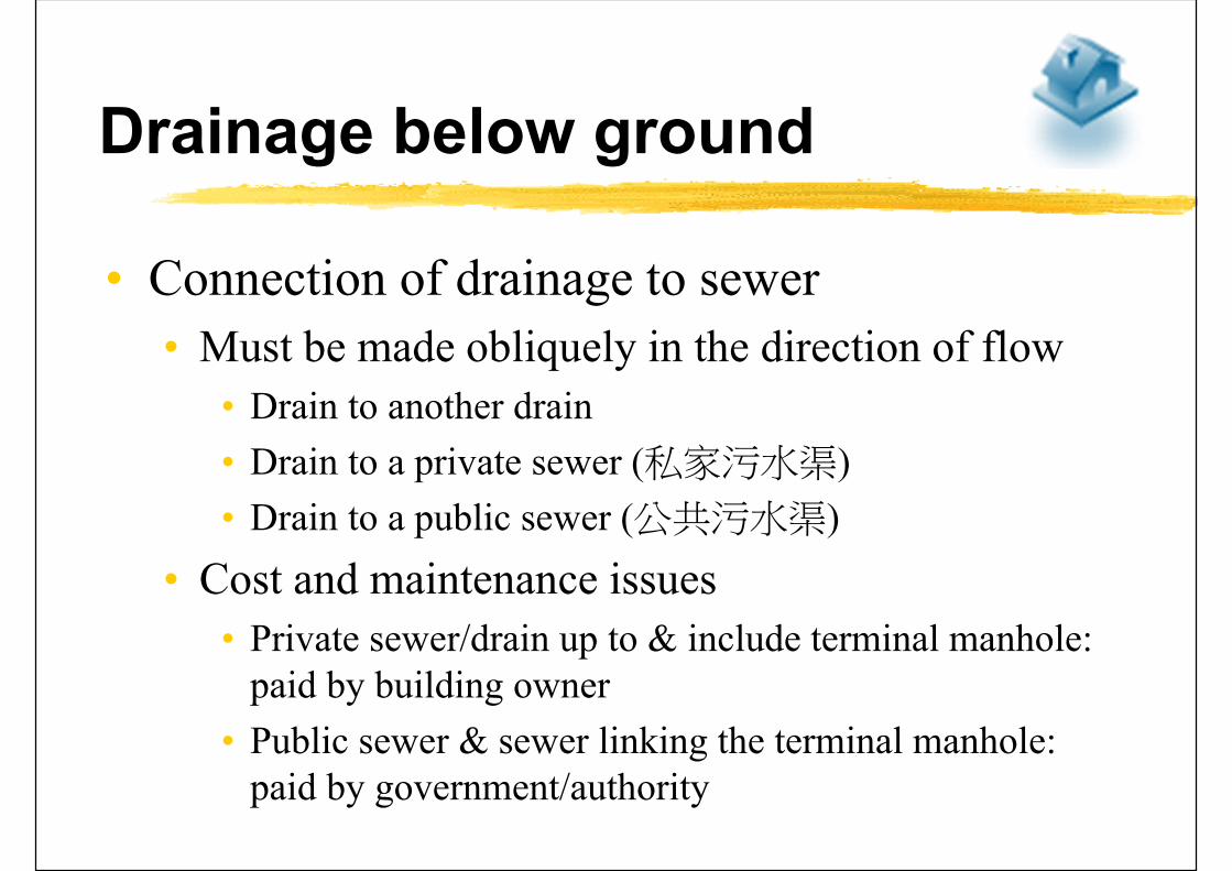
Drainage below ground
• Connection of drainage to sewer
• Must be made obliquely in the direction of flow
• Drain to another drain
• Drain to a private sewer (私家污水渠)
• Drain to a public sewer (公共污水渠)
• Cost and maintenance issues
• Private sewer/drain up to & include terminal manhole: paid by building owner
• Public sewer & sewer linking the terminal manhole: paid by government/authority
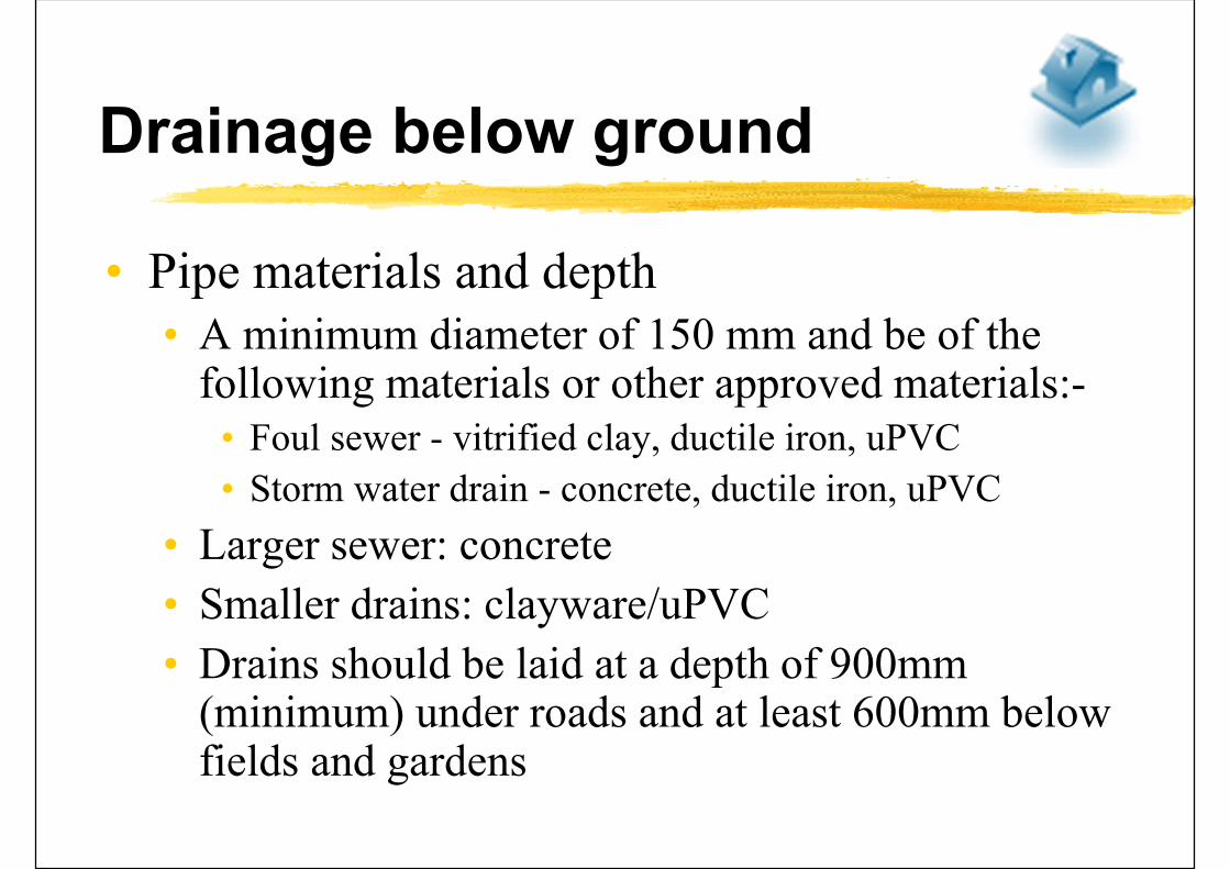
Drainage below ground
• Pipe materials and depth• A minimum diameter of 150 mm and be of the
following materials or other approved materials:-• Foul sewer - vitrified clay, ductile iron, uPVC
• Storm water drain - concrete, ductile iron, uPVC
• Larger sewer: concrete
• Smaller drains: clayware/uPVC
• Drains should be laid at a depth of 900mm (minimum) under roads and at least 600mm below fields and gardens

Drainage below ground
• Underground drainage pipe
• Foul sewers should be designed so that the velocity of the flow will exceed the self-cleansing velocity on a regular basis
• As a general guide, the minimum fall of foul sewers is:
• Pipe diameter 100 mm:- Fall 1:40
• Pipe diameter 150 mm:- Fall 1:70
• Pipe diameter 225 mm:- Fall 1:100
• Pipe diameter 300 mm:- Fall 1:150
Drainage below ground
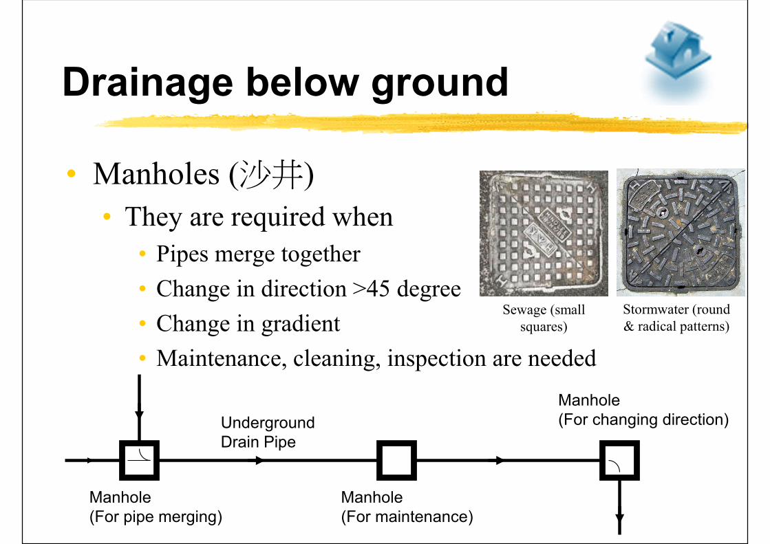
• Manholes (沙井)
• They are required when
• Pipes merge together
• Change in direction >45 degree
• Change in gradient
• Maintenance, cleaning, inspection are needed
Manhole (For pipe merging)
Underground Drain Pipe
Manhole(For maintenance)
Manhole(For changing direction)
Sewage (small squares)
Stormwater (round & radical patterns)
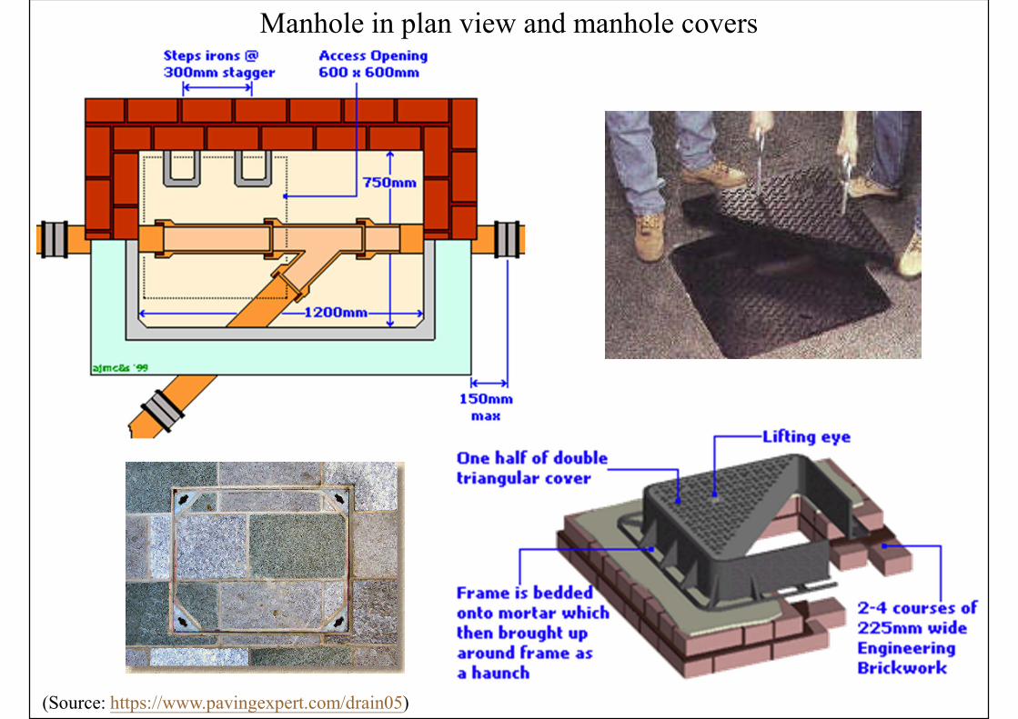
Manhole in plan view and manhole covers
(Source: https://www.pavingexpert.com/drain05)
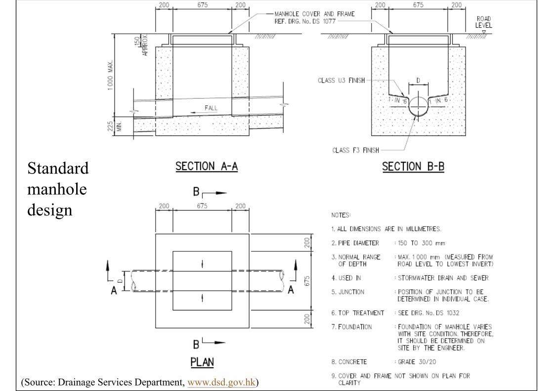
(Source: Drainage Services Department, www.dsd.gov.hk)
Standard manhole design
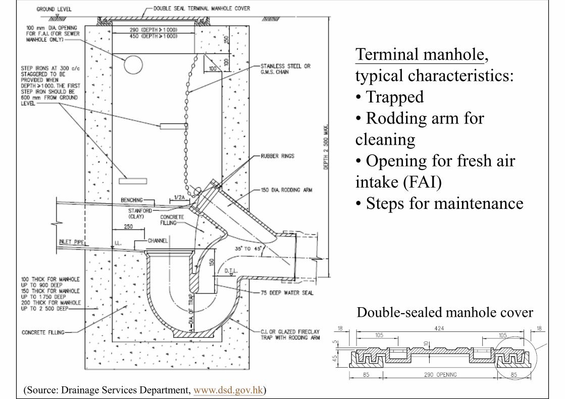
Terminal manhole, typical characteristics:• Trapped• Rodding arm for cleaning• Opening for fresh air intake (FAI)• Steps for maintenance
Double-sealed manhole cover
(Source: Drainage Services Department, www.dsd.gov.hk)
(Source: Drainage Services Department, www.dsd.gov.hk)
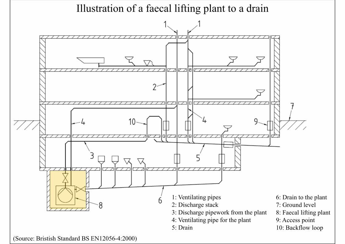
(Source: Bristish Standard BS EN12056-4:2000)
Illustration of a faecal lifting plant to a drain
1: Ventilating pipes2: Discharge stack3: Discharge pipework from the plant4: Ventilating pipe for the plant5: Drain
6: Drain to the plant7: Ground level8: Faecal lifting plant9: Access point10: Backflow loop
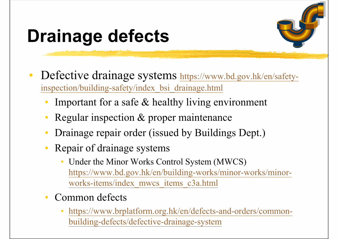
Drainage defects
• Defective drainage systems https://www.bd.gov.hk/en/safety-
inspection/building-safety/index_bsi_drainage.html
• Important for a safe & healthy living environment
• Regular inspection & proper maintenance
• Drainage repair order (issued by Buildings Dept.)
• Repair of drainage systems• Under the Minor Works Control System (MWCS)
https://www.bd.gov.hk/en/building-works/minor-works/minor-works-items/index_mwcs_items_c3a.html
• Common defects• https://www.brplatform.org.hk/en/defects-and-orders/common-
building-defects/defective-drainage-system
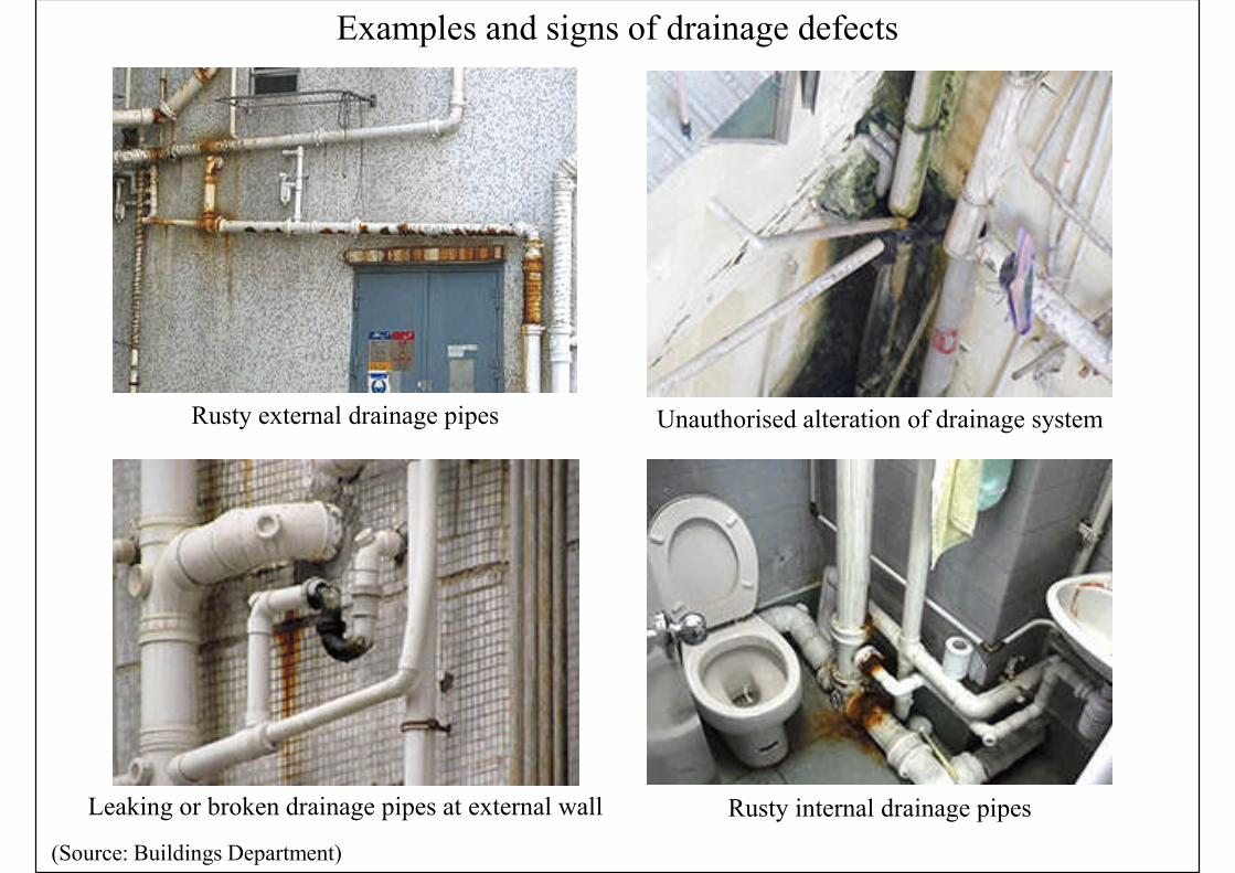
Examples and signs of drainage defects
(Source: Buildings Department)
Unauthorised alteration of drainage system
Rusty internal drainage pipesLeaking or broken drainage pipes at external wall
Rusty external drainage pipes
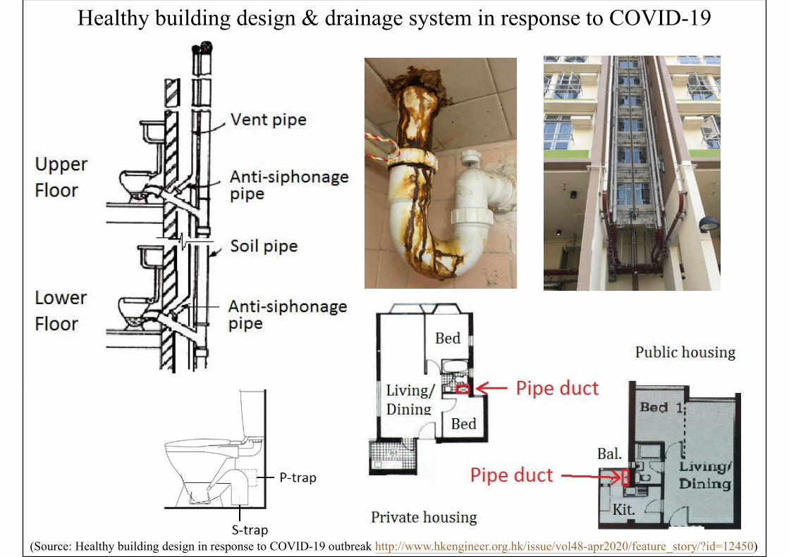
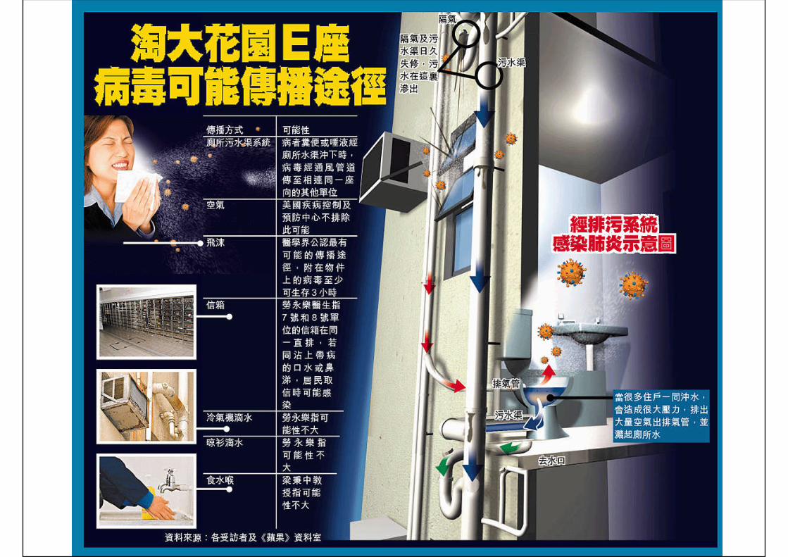
Healthy building design & drainage system in response to COVID-19
(Source: Healthy building design in response to COVID-19 outbreak http://www.hkengineer.org.hk/issue/vol48-apr2020/feature_story/?id=12450)
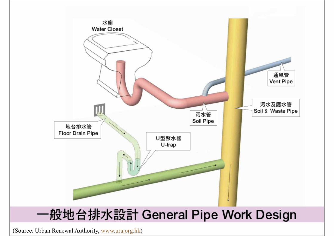
(Source: Urban Renewal Authority, www.ura.org.hk)
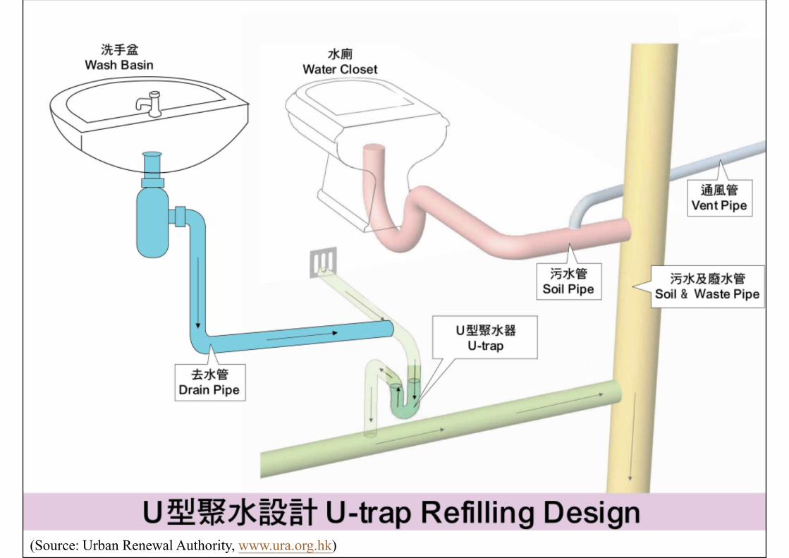
(Source: Urban Renewal Authority, www.ura.org.hk)
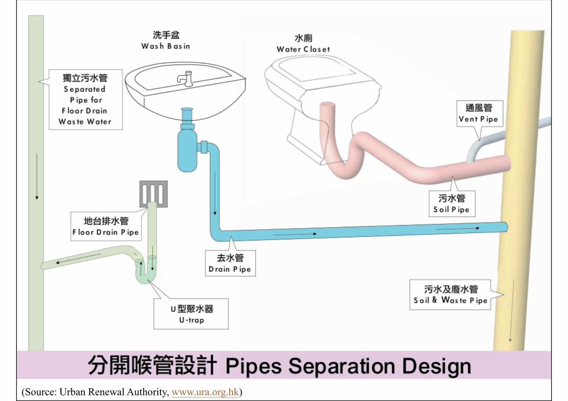
(Source: Urban Renewal Authority, www.ura.org.hk)
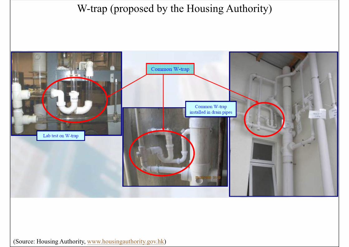
(Source: Housing Authority, www.housingauthority.gov.hk)
W-trap (proposed by the Housing Authority)
References
• CIBSE, 2014. Public Health and Plumbing Engineering, CIBSE Guide G, Chartered Institution of Building Services Engineers (CIBSE), London.
• DSD, 2018. Stormwater Drainage Manual: Planning, Design and Management, 5th ed., Drainage Services Department (DSD), Hong Kong. https://www.dsd.gov.hk/EN/Files/Technical_Manual/technical_manuals/Stormwater_Drainage_Manual_Eurocodes.pdf
• Hall F. & Greeno R., 2017. Building Services Handbook, 9th ed., Routledge, Oxon & New York.
• IOP, 2002. Plumbing Engineering Services Design Guide, [New ed.], Institute of Plumbing, Hornchurch, Essex, UK.