testing & commissioning procedure for plumbing and drainage
TRANSCRIPT
TESTING AND COMMISSIONING PROCEDURE
FOR
PLUMBING AND DRAINAGE INSTALLATION
IN
GOVERNMENT BUILDINGS
OF
THE HONG KONG SPECIAL ADMINISTRATIVE REGION
2012 EDITION
ARCHITECTURAL SERVICES DEPARTMENT
THE GOVERNMENT OF THE HONG KONG SPECIAL ADMINISTRATIVE REGION
PREFACE
This Testing and Commissioning (T&C) Procedure aims to lay down the minimum
testing and commissioning requirements to be carried out on Plumbing and Drainage
Installation in Government Buildings of the Hong Kong Special Administrative Region
(HKSAR). Such requirements are applicable to both new installations upon completion and
existing ones after major alteration.
The present edition was developed by the Plumbing and Drainage Specialist
Support Group that was established under the Building Services Branch Technical
Information and Research & Development Committee of the Architectural Services
Department (ArchSD). This T&C Procedure had incorporated the latest changes in
corrigendum no. GSPD01-2012 for the 2012 edition of the General Specification for
Plumbing and Drainage Installation.
With the benefit of information technology, electronic version of this new edition is
to be viewed on and free for download from the ArchSD Internet homepage. As part of the
Government’s efforts to limit paper consumption, hard copies of this T&C Procedure will
not be put up for sale.
The ArchSD welcomes comments on content of this T&C Procedure at any time
since the updating of this T&C Procedure is a continuous process to tie in with
technological advances.
DISCLAIMER
This T&C Procedure is solely compiled for use on Plumbing and Drainage
Installation carried out for or on behalf of the ArchSD in Government buildings of the
HKSAR.
There are no representations, either expressed or implied, as to the suitability of this
T&C Procedure for purposes other than that stated above. The material contained in this
T&C Procedure may not be pertinent or fully cover the extent of the installation in non-
government buildings. Users who choose to adopt this T&C Procedure for their works are
responsible for making their own assessments and judgement of all information contained
here. The ArchSD does not accept any liability and responsibility for any special, indirect
or consequential loss or damages whatsoever arising out of or in connection with the use of
this T&C Procedure or reliance placed on it.
Table of Contents PD_TCP
Page 1 of 2 2012 Edition
TABLE OF CONTENTS
Page
1. Introduction 1
2. Objectives of the Testing and Commissioning (T&C) Works 1
3. Scope of the T&C Works 2
3.1 Testing and Inspections during Construction 2
3.2 Functional Performance Tests 2
3.3 Commissioning and Statutory Inspections 3
3.4 Documentation and Deliverables 4
3.5 General Commissioning Requirements 4
3.6 General Testing Requirements 6
4. T&C Procedures 6
4.1 Cold Water Supply Installation 6
4.1.1 Test and Inspections during Construction 6
4.1.2 Functional Performance Tests 14
4.1.3 Commissioning and Statutory Inspections 18
4.2 Hot Water Supply Installation 23
4.2.1 Hot Water Boiler and Calorifier System 23
4.2.2 Solar Water Heating System 23
4.2.3 Hot Water Supply Distribution System 23
4.3 Flushing Water Supply Installation 23
4.3.1 Flushing Water Supply Distribution System 23
4.4 Foul Water Drainage Installation – Underground System 23
4.4.1 Water Test 23
4.4.2 Smoke Test 25
4.4.3 Air Test 25
4.4.4 Test for Manhole 27
Table of Contents PD_TCP
Page 2 of 2 2012 Edition
TABLE OF CONTENTS
Page
4.5 Foul Water Drainage Installation – Aboveground System 28
4.5.1 Water Test 28
4.5.2 Air Test 29
4.5.3 Functional Performance Test 30
4.6 Surface Water Drainage Installation – Underground System 31
4.6.1 Water Test 31
4.6.2 Smoke Test 32
4.6.3 Air Test 33
4.6.4 Test for Manhole 34
4.7 Surface Water Drainage Installation – Aboveground System 35
4.7.1 Water Test 35
4.7.2 Air Test 36
4.7.3 Functional Performance Test 37
4.8 Calibrated Equipment 38
Annex
Annex I Testing and Commissioning Progress Chart for Plumbing and
Drainage Installation
I_1
Annex II Testing and Commissioning Certificate on Plumbing and Drainage
Installation
II_1
Part 1: Details of Project
II_1
Part 2: Declaration
II_1
Part 3: Item Inspected and Tested II_2
Part 4: Test Record attached to the Test Certificate II_24
Annex III List of Calibrated Instrument Necessary for the T&C Works III_1
Annex IV Sampling Report IV_1
PD_TCP
Page 1 of 39 2012 Edition
Testing and Commissioning Procedure for
Plumbing and Drainage Installation
1. Introduction
The procedures stated in this T&C Procedure cover the activities in preliminary tests
and inspections, functional performance tests and the commissioning of newly
completed installations and existing ones after major alteration. They are so compiled
to facilitate the work of Project Building Services Engineer (PBSE) and Project Site
Staff, who are appointed as the Architect’s Representatives, in the following aspects
with respect to testing and commissioning (T&C):-
(a) To vet and approve the T&C procedures proposed and submitted by the contractor
for the Plumbing and Drainage Installation (PD Contractor);
(b) To witness those T&C procedures as specified; and
(c) To accept the T&C certificates and other supporting data.
The PD Contractor shall carry out the T&C works as detailed in this T&C Procedure.
Supplementary T&C plans may be proposed by the PD Contractor as appropriate and
agreed by PBSE, e.g. for special equipment supplied and/or installed by the PD
Contractor.
The administrative requirements for T&C works are in general as specified in the
General Specification for Plumbing and Drainage Installation 2012 Edition and all
current corrigenda/amendments thereto published before the date of first tender
invitation for the Contract issued by the ArchSD (the General Specification).
All words and expressions shall have the meaning as assigned to them under the
General Specification unless otherwise specified herein.
2. Objectives of the T&C Works
The objectives of the T&C works are:-
(a) To verify proper functioning of the equipment/system after installation;
(b) To verify that the performance of the installed equipment/systems meet with the
specified design intent through a series of tests and adjustments; and
(c) To capture and record performance data of the whole installation as the baseline
for future operation and maintenance.
For the avoidance of doubt, depending on the specific demands of individual
installation, the PBSE may require additional or substitute T&C works in regard to any
elements in the installation other than those indicated in this T&C Procedure.
PD_TCP
Page 2 of 39 2012 Edition
3. Scope of the T&C Works
3.1 Tests and Inspections during Construction
The purpose of these tests is to ensure that all components and systems are in a
satisfactory and safe condition before start up. Preliminary adjustment and
setting of equipment at this stage shall also be carried out at the same time to
pave way for the coming functional performance tests.
Before carrying out any test, the PD Contractor shall ensure that the Plumbing
and Drainage Installation (Installations) complies with all relevant statutory
requirements and regulations. The T&C works shall also comply with all site
safety regulatory requirements currently in force. In particular, the PD
Contractor shall note the following:-
(a) Electricity Ordinance (Cap. 406), and other subsidiary legislation;
(b) Code of Practice for the Electricity (Wiring) Regulations published by the
EMSD;
(c) Occupational Safety and Health Ordinance (Cap. 509), and other subsidiary
legislation made under the Ordinance;
(d) Factories and Industrial Undertakings Ordinance (Cap. 59), and other
subsidiary legislation made under the Ordinance, including but not limited
to Construction Site (Safety) Regulations;
(e) Electricity supply rules of the relevant power supply companies; and
(f) Code of Practice for Prevention of Legionnaires’ Disease.
3.2 Functional Performance Tests
The purpose of functional performance tests is to demonstrate that the
Installations can meet the functional and performance requirements as specified
in the General Specification and/or Particular Specification. Functional
performance tests shall proceed from the testing of individual components to
the testing of different systems in the Installations.
The PD Contractor may have to make temporary modifications as the tests
proceed. The specific tests required and the order of tests will vary depending
on the type and size of systems, number of systems, sequence of construction,
interface with other installations, relationship with the building elements and
other specific requirements as indicated in the General Specification and/or
Particular Specification. The testing of systems may have to be carried out in
stages depending on the progress of work or as proposed by the PD Contractor.
Part of the tests may be required to be carried out in suppliers’ premises in
accordance with the provisions in the General Specification and/or Particular
Specification.
PD_TCP
Page 3 of 39 2012 Edition
Any performance deficiencies revealed during the functional performance tests
must be evaluated to determine the cause. After completion of the necessary
corrective measures, the PD Contractor shall repeat the tests.
If any test cannot be completed because of circumstances that are beyond the
control of the PD Contractor, it shall be properly documented and reported to
the PBSE, who shall then liaise with the relevant parties to resolve the
situation. The PD Contractor shall resume his testing work immediately upon
the attainment of a suitable testing environment.
3.3 Commissioning and Statutory Inspections
Commissioning is the advancement of the Installations from the stage of static
completion to full working conditions and to meet the performance
requirements as specified in the General Specification and/or Particular
Specification. This will include setting into operation and regulation of the
Installations. Fine-tuning of the commissioned system shall be done by the PD
Contractor to match system performance to the actual needs of the building
occupier more closely.
Where necessary, after the proper testing and commissioning of the
Installations, the PD Contractor shall notify the appropriate authority as
specified in the General Specification and/or Particular Specification, through
the PBSE of the completion of the Installations and its readiness for final
inspection.
Where practicable, the PD Contractor shall arrange for inspection by the Water
Authority all underground pipework before it is backfilled or covered up or
prior to concreting on any pipework to be embedded in any structure elements
or concealed on any pipework by architectural features which cannot be easily
removed for inspection after their installation.
The statutory test and inspection herein stated in this T&C Procedure shall
make reference to the following regulations:-
(a) Relevant Regulations under the Waterworks Ordinance (Chapter 102),
such as Waterworks Regulations (WW Reg.), Hong Kong Waterworks
Standard Requirements for Plumbing Installation in Buildings (HKWSR);
(b) Relevant Regulations under the Building (Standards of Sanitary Fitments,
Plumbing, Drainage Works and Latrines) Regulations Chapter 123
Subsidiary Legislation;
(c) Relevant Practice Notes for Authorized Persons, Registered Structural
Engineers and Registered Geotechnical Engineers (i.e. PNAP), and
Practice Notes for Registered Contractors issued by Buildings Department;
(d) Relevant Circular Letters to all Licensed Plumbers and Authorized Persons
issued by Water Supplies Department.
PD_TCP
Page 4 of 39 2012 Edition
3.4 Documentation and Deliverables
The PD Contractor shall submit his proposed T&C procedures together with
the Testing & Commissioning Progress Chart shown in Annex I to PBSE for
approval.
All inspection and T&C results shall be recorded by the PD Contractor in the
appropriate test record forms. A complete set of these forms can be found in
Annex II.
Data recorded in other formats may also be acceptable subject to prior approval
of the PBSE. Upon completion of all the required T&C works, the PD
Contractor’s project engineer shall complete and sign a testing and
commissioning certificate as shown in Part 1 & Part 2 of Annex II to the effect
that the agreed T&C works have been duly carried out.
A functional performance test report covering all measured data, data sheets,
and a comprehensive summary describing the operation of the system at the
time of the functional performance tests shall be prepared and submitted to the
PBSE. Deviations in performance from the General Specification and/or
Particular Specification or the design intent shall be recorded, with a
description and analysis included.
Where required in the General Specification and/or Particular Specification, the
PD Contractor shall conduct a final evaluation of the performance of the
Installations, the results of which shall be included in the commissioning
report.
3.5 General Commissioning Requirements
3.5.1 Systems shall be properly commissioned to demonstrate that all the
equipment deliver the designed capacities and that water flow rate is
properly balanced in accordance with the design.
Prior to any commissioning works, the PD Contractor shall check the
completion of the associated builder’s work and the building services
installations, to ensure that commissioning can be proceeded without
obstruction.
(a) Checking procedures on builder’s work:-
(i) Plant rooms are completed and free of construction debris;
(ii) All plant room doors are fitted and lockable;
(iii) Permanent power supply of sufficient capacity is available and
the PD Contractor is operating a security access procedure to
all plant areas to prevent unauthorised switching of plant.
(The normal security access system is one of "Permit to Work"
arrangement and procedure proposed by the PD Contractor in
PD_TCP
Page 5 of 39 2012 Edition
accordance with the guidelines on "Permit to Work" issued by
the Labour Department.);
(iv) All builder’s work and building services installations in
association with plumbing and drainage installation are
satisfactorily completed;
(v) All external doors, all stairs and lobbies, and toilet doors are
completed and securable;
(b) Checking procedures on plumbing and drainage installation
The PD Contractor shall ensure that:-
(i) Plant room access is restricted to authorised personnel only;
(ii) Provision of power supply for the T&C works; and
(iii) All functional and safety devices are installed and operational.
3.5.2 All aspects of the commissioning procedure shall follow the
recommendations including but not limited to:-
(a) Preliminary checks to ensure that all systems and system
components are in a satisfactory and safe condition before start up;
(b) Preliminary adjustment and setting of all plant and equipment
consistent with eventual design performance;
(c) Energising and setting to work on all plants; and
(d) Final regulation and demonstration that the installation delivers the
correct rate of flow of fluids at the conditions specified in the
Contract documents.
3.5.3 Progressive Commissioning
The PD Contractor shall not wait for completion of every part of the
work but shall arrange for a progressive commissioning programme to
achieve practical overall completion and have the whole work ready to
be handed over by a date to suit the Contract completion date or any
other agreed programme date.
PD_TCP
Page 6 of 39 2012 Edition
3.6 General Testing Requirements
3.6.1 Witness by the PBSE
The final tests shall be carried out in the presence of the PBSE or his
representative, in accordance with the requirements of witness T&C as
stipulated in the Building Services Branch Instructions. The PD
Contractor shall give at least 72 hours advance notice, in writing, when
any part or parts of the installation will be tested.
3.6.2 Test Equipment and Labour
The PD Contractor shall provide all the necessary staff, skilled labour,
testing gear (including pumps, tools, water flow instruments etc.) and
attendants for all tests including those by Specialist employed under the
Sub-contractor. The PD Contractor shall be solely responsible for the
proper filling, emptying and flushing of the systems and pipes to be tested
and shall make good any defects emerging from the tests, or made
manifest under testing or re-testing, until the whole of the Installations is
free from defect and is in complete working order to the satisfaction of
the PBSE.
3.6.3 Tests under Operating Conditions
The PD Contractor shall include the hydraulic and functional
performance tests under operating conditions, on the whole installation to
the entire satisfaction of the PBSE.
4. T&C Procedures
4.1 Cold Water Supply Installation
4.1.1 Test and Inspections during Construction
Certain tests will be carried out on different systems of the installation
during construction to ensure their suitability for operating at the design
conditions. Certificates of such tests have to be issued together with
certificates of any work tests.
4.1.1.1 Work Tests
(a) Work tests shall be carried out in accordance with the type
normally associated with the specified item of equipment and to
the standards as laid down in the General Specification and/or
Particular Specification.
(b) Work static pressure tests shall be carried out for all items of plant
and equipment, as laid down in the Specification and the Contract.
PD_TCP
Page 7 of 39 2012 Edition
4.1.1.2 Weld in Piped Services
(a) The PBSE reserves the right to inspect at random 2% of the welded
joints. Should any of the above welds prove faulty in materials or
workmanship, further removal of welds may be ordered up to a total
of 4% of the welded joints. If any of the welds fail the tests, it is
sufficient to conclude that an operative is not consistent in standard.
The PBSE may order any number of the operative’s welds to be
removed. The PD Contractor shall be responsible for cutting out and
repair of all such welds for inspection.
(b) At least 2 welds per operative shall be inspected. Each welder
employed on the works shall be allocated an identification number
and each site weld shall be stamped with the appropriate
identification number to identify the operative.
(c) In addition to the above, each weld made on pipes and fittings
having a nominal diameter of 350 mm and larger, and a 5% sample
of all welds on pipes and fittings 300 mm diameter and below shall
be inspected using an approved non destructive inspection process,
e.g. radiographic or ultrasonic methods. The PD Contractor’s
attention is drawn to the magnitude of this task, the constraints of the
water mains, and the time frame within which testing must be
carried out. Such non-destructive testing shall be carried out by
specialized laboratories that both perform the tests and analyse the
results.
4.1.1.3 Pre-commissioning Checks of Water Distribution System
4.1.1.3.1 System Cleanliness
Irrespective of the precautions taken during the construction
stage to keep the internal surfaces of pipework clean, the
following procedures shall be used to clean the system.
(a) divide the pipework system into self-draining sections
so that the maximum possible flushing rate is achieved;
(b) isolate or bypass items which are particularly sensitive
to dirt such as pumps, small bore coils and tubes.
Washers, feed and other tanks which may have
accumulated with deposits during manufacturing or
installation shall also be isolated and flushed
independently; and
(c) where make-up or feed tanks are used for flushing,
ensure that the maximum possible pressure is sustained
on the system during the flushing process. This may
necessitate the provision of a temporary parallel feed of
mains water into the tank where the ball valve has
limited capacity. This T&C Procedure assumes that the
connection of the section from the tank is at a high
PD_TCP
Page 8 of 39 2012 Edition
point in the section being flushed. The flushing water
wherever appropriate, shall be recirculated with
suitable filtration to reduce the water demand and
wastewater discharge.
(d) The PD Contractor shall ensure that:-
(i) flushing is carried out from the upper to the
lower sections of a multi-section system, flushing
with the lowest point; initial flushing shall
always be from small bore to large bore pipe;
(ii) the large bore outlet is not opened until the
section being flushed is fully primed;
(iii) the maximum possible flow rates are used; and
(iv) flushing continues until the outflow runs clear.
Where facilities exist, cleaning of systems can be achieved
by circulation of the medium in order to collect dirt at
filters or other selected points in the system. Where
circulation is achieved by the use of a pump, this action
shall be deferred until the pump has been set to work in
accordance with the relevant paragraph below. The
circulating velocity shall be 1.5 times of normal water
velocity in pipe.
4.1.1.3.2 State of the System
The PD Contractor shall check:-
(a) that where special valve packing is required, e.g. grease
in medium or high temperature system, this shall be in
accordance with manufacturer’s instructions;
(b) that pressure tests have been completed throughout;
(c) that the system has been cleaned in accordance with
para. 4.1.1.3.1;
(d) that permanent water connections have been made; and
(e) that water treatment is available if specified.
4.1.1.3.3 Check of System before Filling
The PD Contractor shall check:-
(a) that probes, pockets, pressure gauges, siphons, orifice
plates and taps, and air vents are installed;
PD_TCP
Page 9 of 39 2012 Edition
(b) that drains and overflows are connected and free from
blockage;
(c) that connections to the appliances and fittings are
correct in relation to the design water flow direction;
(d) that control and non-return valves are installed the right
way round;
(e) that relief valves are installed as specified and are free
to operate;
(f) that relief valve outlets are piped away to suitable drain
points;
(g) the expansion devices for alignment and freedom from
obstruction;
(h) the presence of special pump priming devices where
specified;
(i) that the strainer meshes are of the correct grade and
material;
(j) that the changeover devices for duplex strainers are
operative and that there are means of isolation for
single strainers;
(k) that washers, tanks, nozzles and filters are clean;
(l) that tank covers are provided where specified;
(m) that drain cocks are closed and other valves are left
open or closed according to the plan for filling;
(n) that the feed connection is in its correct location; and
(o) that all pipework and fittings are adequately supported,
guided and/or anchored where applicable.
4.1.1.3.4 Mechanical Checks
(a) Pumps
The PD Contractor shall check:-
(1) the external cleanliness of the pumps, remove
and clean and replace all strainers;
(2) that the flow direction is correct;
PD_TCP
Page 10 of 39 2012 Edition
(3) that all components, bolts, fixings, tie bars etc.,
are secured;
(4) that the impellers are free to rotate;
(5) the level and plumb of pump and motor shaft and
slide rails; (direct drive pumps require particular
attention in this respect);
(6) the anti-vibration mountings for correct
deflection;
(7) that the correct drivers are fitted;
(8) that the pipework imposes no strain at the pump
connections;
(9) the securing and alignment of pulleys and
couplings;
(10) the belt tension and match;
(11) the cleanliness of the bearings;
(12) that the lubricant is fresh and of the correct
grade;
(13) that the coolant is available at the bearings when
specified;
(14) that glands are correctly packed and the gland
nuts are finger-tight only, pending adjustment to
correct drip rate after start-up; and
(15) that drive guards are fitted and the access for
speed measurement is provided.
(b) Pump Panel
The PD Contractor shall check:-
(1) that all internal control panels are properly
installed;
(2) that all components, bolts, fixings, tie bars etc., are
secured;
(3) that equipment is dust-free and in good order;
(4) that cables and terminals have good protection;
and
PD_TCP
Page 11 of 39 2012 Edition
(5) that conduits and wirings are of appropriate size.
(c) Motorized Valves and Float Switches
The PD Contractor shall check:-
(1) that the valves are installed the correct way round;
(2) that the valve spindles are free to move;
(3) for freedom from excessive looseness;
(4) the fit of pins;
(5) the rigidity of the mountings;
(6) the stiffness of the linkage members;
(7) the tightness of locking devices; and
(8) the bearing lubrication.
4.1.1.3.5 Electrical Checks
Prior to the initial running of any electrically driven pump,
valve or electric water heater, the following procedures
shall be adopted.
(a) With all Electrical Supplies Isolated
The PD Contractor shall check:-
(1) the local isolation of motor and control circuits;
(2) that there are no unshrouded live components
within the panels;
(3) that the panels and switchgears are clean;
(4) that the motor and surrounding areas are clean
and dry;
(5) that the transit packing has been removed from
contactors and other equipment;
(6) that there is no mechanical damage to
switchgears and that thermostats are of a suitable
range to operate at ambient temperature, see para.
4.2.1.2;
(7) that all mechanical checks on the pump and
motor or valve are completed, see para. 4.1.5.4;
PD_TCP
Page 12 of 39 2012 Edition
(8) that all connections are tight on busbars and
wirings;
(9) that the internal links on the starter are correct;
(10) that all power and control wirings have been
completed in detail to the circuit diagram, paying
special attention to circuit for start-delta
connected or specially wound motors;
(11) that the fuse ratings are correct;
(12) that the starter overloads are set correctly in
relation to the motor name-plate full load current;
(13) that the dashpots are charged with the correct
fluid and the time adjustments and levels are
identical;
(14) that insulation tests on the motor have been
performed satisfactorily;
(15) that the adjustable thermal cut-outs are set
correctly (check manufacturers’ test certificates);
and
(16) that all cover plates are fitted.
(b) With the Electrical Supply Available
The PD Contractor shall check:-
(1) check that the declared voltage range is available
on all supply phases;
(2) where motor powers are substantial or reduced
voltage starting or complex interlocks are
involved, the control circuit logic and the starter
operation shall be tested before the motor is
rotated. The supply shall first be isolated by the
withdrawal of the 2 power fuses not associated
with the control circuit or the disconnection of
cables. The “red” phase shall be used for control
circuit normally. The control circuit fuse must be
checked to ensure that it is rated to give the
correct discriminatory protection to the control
circuit cables. The control circuit shall be
activated and the starter operation observed.
Adjust the timers. Check for positive operation
of all contactors, relays and interlocks. Finally,
open the isolators, reinstate the power
connections and close the isolators;
PD_TCP
Page 13 of 39 2012 Edition
(3) where small motors have direct-on-line starting
and simple control circuits, the starter operation,
etc., shall be checked when first starting the
motor; and
(4) never energise electronic valve motors until the
checks in para. 4.1.1.3.4(c) have been completed.
4.1.1.3.6 System Filling
All water tanks shall, after erection, be filled with water and
shall remain filled for at least 24 hours during which all
joints shall be carefully examined. Any defect shall be
rectified immediately and the test repeated.
Before finally charging, the water systems shall be
thoroughly flushed and all strainers, filters, etc. cleaned or
replaced.
Charge the system with water by filling from the bottom
upwards forcing the air to high points – for venting to
atmosphere. Careful consideration shall be given to the
stage of valves and air vents before and during filling to
avoid air-locks and excessive spillage. Take care not to
exceed the working pressure of the system when filling
from a high pressure source. When the whole system is
filled, disconnect the filling source, open the permanent
supply and adjust the tank level.
4.1.1.3.7 Hydraulic testing for water distribution pipe work system
(a) General
All water distribution pipework systems shall be
hydraulically tested in sections as installation work
progresses.
(b) Test Pressure
The hydraulic test pressure shall be 1.5 times the
maximum working pressure.
(c) Precautions
Before hydraulic tests are carried out, all safety valves,
gauges, etc. shall be effectively isolated or removed.
This safety equipment shall be effectively tested at
their design working pressure during commissioning of
the installation.
PD_TCP
Page 14 of 39 2012 Edition
(d) Method of Testing
For a satisfactory and acceptable test, the pressure shall
be maintained for a period of at least one hour or as
otherwise stated in the Particular Specification, without
loss of pressure or loss of water or leakage after all
weak joints, defective fittings and pipes disclosed by
the initial application of the test are rectified. During
the final testing period, the PBSE or his representative
shall be invited to witness the tests. All sections of the
work under test shall be accessible for inspection and
selected welds shall be hammer tested.
(e) Hydraulic Test Certificates
Certificates of all hydraulic tests made on the Site shall
be forwarded to the PBSE for approval. A separate and
duplicated set of the PD Contractor’s installation/shop
drawings shall be provided for the purpose of keeping
accurate records of site tests. One copy will be kept by
the PBSE’s representative on the Site and the other
retained by the PD Contractor.
(f) Details on Test Certificate
All test certificates shall be signed by the PD
Contractor’s authorized site representative and by the
PBSE or his representative who has witnessed the tests.
All test certificates shall contain the following
particulars :-
- Date of test
- Apparatus or section under test
- Makers number (if any)
- Nature, duration and conditions of test
- Result of test
- Name of PD Contractor’s representative (in block
letter) in charge of test
- Name of Employer’s representative at witness the test
A blank test certificate form shall be submitted by PD
Contractor for PBSE’s approval prior to carrying out
the actual test on the Site.
4.1.2 Functional Performance Tests
4.1.2.1 Pump
4.1.2.1.1 Prior to Pump Started-Up, the PD Contractor shall check
that:-
(a) all normally open isolating and regulating valves are
PD_TCP
Page 15 of 39 2012 Edition
fully open and that all normally close valves are closed;
(b) the direction sign of all non-return valves is along the
same discharge direction of associated pumps;
(c) the horizontal or vertical alignment of all flexible joints
is within the tolerances recommended by
manufacturers’ installation guideline;
(d) fully open the return and close the flow valve on the
pump, close valves on standby pump. Closing the flow
valve on the duty pump will limit the initial starting
current, which is usually excessive at the first time a
pump is running due to bearing stiffness.
4.1.2.1.2 Initial Running of Electrically Driven Centrifugal Pump Set
4.1.2.1.2.1 Initial Start
On activating the motor starter, the PD Contractor shall
check that:-
(a) the direction and speed of rotation of the motor shaft
are correct;
(b) the motor, pump and drive are free from vibration and
undue noise;
(c) the motor running current on all phases are balanced
and do not exceed motor nameplate rating The flow
valve can be opened at this point to raise the running
current to say 50 per cent of the name-plate full load
current;
(d) there is no sparking at the commutator or slip rings for
d.c. or slip ring motors;
(e) there is no overheating of the motor (see BS EN
60947-4-1 [2004] and BS EN 60034-3 [2005]);
(f) there is no seepage of lubricant from the housing;
(g) the water flow to water-cooled bearings is sufficient;
(h) the motor running current are correctly matching with
the speed as specified by manufacturer’s pump data
sheet on multi-speed motors.
4.1.2.1.2.2 Initial Run
(a) a light load shall be sustained until the Commissioning
Engineer is satisfied from the checks listed in para.
PD_TCP
Page 16 of 39 2012 Edition
4.1.2.1.2.1 and from motor insulation test readings that
further load may be applied. Repetitive starting of the
motor shall be avoided to prevent over-stressing of the
fuses, switchgear and motor;
(b) gradually open the discharge valve from closed
position until the motor current reaches either the
design value or the motor full load current, whichever
is the lower;
(c) check the pump pressure developed by means of the
pump altitude gauges against the design pressure. If
excessive pressure is developed at this stage, the cause
shall be investigated and rectified; and
(d) adjust the discharge valve so that the flow as
determined roughly from the pump characteristic is
between 100 and 110 per cent of the design value. Note
that the motor full load current is not exceeded.
4.1.2.1.2.3 Running-in Period
(a) the pump shall be run in accordance with the
manufacturer’s recommendations and shall be under
fairly continuous observation. It shall not be left
running outside normal working hours unless attended;
(b) check that the bearings and motor temperature remain
steady, that no noise or vibration develops and that no
bolts or fixing works is loose;
(c) close the valves to the vulnerable units to avoid
blockage at the coils of terminal units;
(d) vent all high points from time to time;
(e) adjust the gland nuts of the pump glands to give the
correct drip rate; (not applicable to mechanical seals.)
and
(f) after 8 hours of running, check all strainers. If these are
clean, regulation can commence. Otherwise, clean the
strainers and run again for at least 8 hours and then re-
check.
(Remark: Observations afterwards may then become less
frequent, but it is advisable, while commissioning other
parts of the system later, to check the pump from time to
time.)
PD_TCP
Page 17 of 39 2012 Edition
4.1.2.1.2.4 Standby Pump
(a) on installations with a standby pump, this standby
pump shall also be commissioned;
(b) this pump can be checked against the other duty pump.
In the unlikely event of failure of the duty pump,
commissioning can continue using standby pump; and
(c) carry out a full diagnosis of the reasons for the failure
of the duty pump before energizing the standby pump
to ensure that any contributory causes are remedied.
4.1.2.1.3 Regulation of Water Flow
4.1.2.1.3.1 Principles of water flow rate measurement & registration
(a) the installation location of the devices have to follow
the manufacturers’ recommendation in order to obtain
accurate flow measurement results. The devices may be
a venturi-meter, an orifice plate, a control valve with
known calibrated flow characteristics, a calibrated
regulation valve, electromagnetic flow sensors or any
device with a constant flow coefficient and calibration
chart;
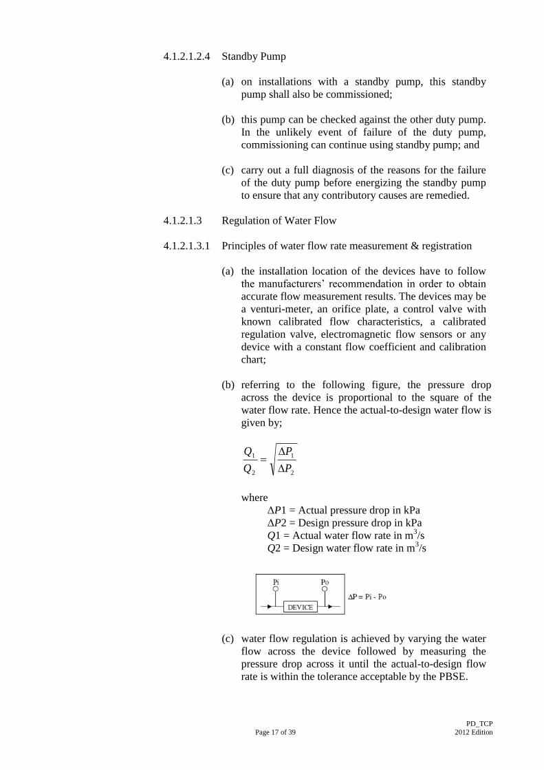
(b) referring to the following figure, the pressure drop
across the device is proportional to the square of the
water flow rate. Hence the actual-to-design water flow is
given by;
2
1
2
1
P
P
Q
Q
where
ΔP1 = Actual pressure drop in kPa
ΔP2 = Design pressure drop in kPa
Q1 = Actual water flow rate in m3/s
Q2 = Design water flow rate in m3/s
(c) water flow regulation is achieved by varying the water
flow across the device followed by measuring the
pressure drop across it until the actual-to-design flow
rate is within the tolerance acceptable by the PBSE.
PD_TCP
Page 18 of 39 2012 Edition
4.1.2.1.4 Demonstration
The PD Contractor shall perform dummy testing by
inputting at least 20 sets of water flow rates or as specified
in the Particular Specification to test the stability of the
system and the timing required for adjusting. The values of
the dummy testing water flow rates shall be submitted for
approval at least 2 weeks before T&C.
4.1.3 Commissioning and Statutory Inspections
4.1.3.1 Licensed Plumber (LP)
Provided that all pipes and fittings intended to be installed are approved
by the Water Authority, the LP shall be engaged by the PD Contractor
and required to submit Application Form WWO46 (Part I and II) to
WSD for notification before commencement of plumbing work.
Application Form WWO46 (Part IV) shall be submitted to WSD by LP
for notification of final inspection of the plumbing work after the
completion of the plumbing work.
4.1.3.2 Connection Pipe Provision
The PD Contractor shall arrange all necessary inspections and approvals
from the statutory authorities, i.e. Water Supplies Department (WSD), in
accordance with the Waterworks Ordinance (Chapter 102).
4.1.3.3 Water Meter / Check Meter Provision
The PD Contractor shall arrange all necessary inspections and approvals
from the statutory authorities, i.e. Water Supplies Department (WSD), in
accordance with the Waterworks Ordinance (Chapter 102).
4.1.3.4 Water Storage Cistern Provision
The PD Contractor shall arrange all necessary inspections and approvals
from the statutory authorities, i.e. Water Supplies Department (WSD), in
accordance with the Waterworks Ordinance (Chapter 102).
4.1.3.5 Cleaning and Disinfection
All water distribution pipework and water storage tanks shall be
thoroughly flushed clean to remove rust, sludge and sediment upon
commissioning. Portable water distribution pipework and associated
water storage tanks shall be further disinfected before they are put into
operation, to remove organic matter which encourages the growth of
biofilms and subsequently deterioration of water quality.
The PD Contractor shall submit a cleaning and disinfection plan
indicating the scope of work, detail of the compartmentation if any, work
schedule, method statement for the disinfection work, procedures and
PD_TCP
Page 19 of 39 2012 Edition
equipment for checking and testing, location of sampling, method
statement for the de-chlorination, etc. for PBSE’s approval prior to
carrying out the disinfection work.
4.1.3.5.1 Methodology of Disinfection
4.1.3.5.1.1 Upstream Pipework before Water Meter
The PD Contractor shall arrange all necessary cleaning and
disinfection of the water pipework upstream of the water
meter, i.e. from the incoming fresh water mains to the water
meter/check meter of the premise, to the satisfaction of
Water Supplies Department (WSD).
The cleaning and disinfection requirements and procedures
shall follow Water Supplies Department (WSD)'s current
guidelines on cleaning and disinfection. Details of WSD's
guidelines are available at the following:
WSD’s guide for fresh water mains of inside services
http://www.wsd.gov.hk/en/pldc1/index.html
WSD’s guide for fresh water storage tanks
http://www.wsd.gov.hk/en/pldc2/index.html
The potable water supply installation shall be filled
completely with a homogeneous solution of chloride of
lime for disinfection. The concentration of the solution has
to meet the requirement that when the water piping is filled
up with water, the free chlorine in the water will be at least
30 p.p.m. The potable water supply installation shall be
under disinfection for 24 hours. Persons undertaking the
disinfection shall be suitable trained and qualified.
4.1.3.5.1.2 Downstream Pipework after Water Meter
The PD Contractor shall arrange all necessary cleaning and
disinfection of the potable water supply pipework
downstream after the water meter/check meter and water
storage tanks not more than 7 days before hand over the
water supply system to users for operation. Where the
potable water supply system is not brought into use
immediately after disinfection, it shall be disinfected before
use unless it has been flushed weekly to maintain a flow of
water.
The methodology of disinfection for downstream pipework
after the water meter shall follow BS 8558:2011. The
potable water supply installation shall be filled completely
with chlorinated water at an initial concentration of 50
p.p.m. for a contact period of one hour. If the free residual
chlorine measures at the end of the contact period is less
PD_TCP
Page 20 of 39 2012 Edition
than 30 p.p.m. the disinfection process shall be repeated.
Persons undertaking the disinfection shall be suitable
trained and qualified.
After disinfection, the PD Contractor shall flush the water
pipework thoroughly with potable water. Flushing shall be
continued until there is no evidence of the disinfectant
being present, or is below an acceptable level which is
allowed by WSD.
4.1.3.5.2 Discharge of disinfectant solution
Before water containing high-residual free chlorine is
discharged to drain, it shall be de-chlorinated. Any
discharge of the disinfectant solution shall comply with the
Water Pollution Control Ordinance (Cap. 358). The PD
Contractor shall submit a method statement for the de-
chlorination to PBSE for approval.
4.1.3.5.3 Compartmentation of System for Disinfection
The PD Contractor shall conduct disinfection of the entire
potable water supply installation and it can be divided by
different compartmentation for disinfection if considered
necessary for suiting the prevailing site condition or in case
of different stage(s) or portion(s) of handover, etc. The
proposed compartmentation of potable water supply
installation for disinfection shall be stated in the
disinfection plan and submitted to PBSE for approval prior
to conducting the disinfection work on the Site.
System, or parts of systems shall not be used during the
disinfection process and all outlets shall be marked with
“DISINFECTION IN PROGRESS, DO NOT USE”. In this
respect, the Licensed Plumbers should allow sufficient time
to carry out sampling and analysis. After disinfection, the
entire potable water supply installation should be flushed
thoroughly with potable water.
4.1.3.5.4 Sampling and Analysis
The PD Contractor shall conduct sampling and analysis for
the quality of the potable water supply system upon
completion of disinfection and flushing of the whole system
or of different compartmentation as described in 4.1.3.5.2
(i) Samples shall be taken at the following locations upon
substantial completion of the potable water distribution
system:-
all farthest points of use in the water piping system
from the water supply tank;
PD_TCP
Page 21 of 39 2012 Edition
inlet and outlet of all water supply tanks;
both inlet and outlet to water treatment equipment,
such as water filtration device, ultra-violet
disinfection unit where the water is used for drinking
or food preparation purposes;
beginning, middle and end of distribution branches;
supply points to kitchens;
hot water supply points.
The following procedures shall be used for taking water
sampling at the water taps or water pump outlets: -
remove from the tap any attachments that may cause
splashing. Using a clean cloth, wipe the outlet to
remove any dirt;
turn on the tap at maximum flow and let the water
run for 1–2 minutes;
sterilize the tap for a minute with the flame from a
gas burner or an ignited alcohol-soaked cotton-wool
swab;
carefully turn on the tap and allow the water to flow
for 1– 2 minutes at a medium flow rate. Do not
adjust the flow after it has been set;
take out a bottle and carefully unscrew the cap or
pull out the stopper;
while holding the cap and protective cover face
downwards (to prevent entry of dust, which may
contaminate the sample), immediately hold the
bottle under the water jet, and fill;
left a small air space in the bottle to make shaking
before analysis easier;
place the stopper in the bottle or screw on the cap
and fix the brown paper protective cover in place
with the string.
(ii) Sampling Report form should be made reference in
Annex IV and used to record the sampling data
collected. The PD Contractor shall submit the sampling
report form to PBSE for approval prior to sampling
collection.
4.1.3.5.5 Regular Flushing of pipework
Where the potable water supply installation is not brought
into use immediately after commissioning, the PD
Contractor shall arrange disinfection before put into
operation, unless it has been flushed weekly to maintain a
flow of water.
If the water supply installation is partially handed over for
operation by the users, the PD Contractor shall
PD_TCP
Page 22 of 39 2012 Edition
continuously flush the remaining portion of the system at
regular interval until the whole system has been handed
over for operation to the user or after the issue of Handover
Certificate by the Architect.
4.1.3.5.6 Record of cleaning and disinfection
The PD Contractor shall maintain properly the record of
dates of cleaning and disinfection of the potable water
supply installation and provide the record including the
approved method statements of the cleaning and
disinfection during handover. A notice plate/board should
be provided to record the dates of cleaning of the water
tanks and securely fixed at a conspicuous location easily
accessible and visible by the building management staff.
4.1.3.6 Vibration Tests
Testing for equipment vibration is necessary as an acceptance check to
determine whether equipment is functioning properly and to ensure that
objectionable vibration and noise are not transmitted. As the vibration
acceptance test is based on root mean square (r.m.s) velocity (mm/s)
only, frequency measurement is not required. Vibration measurement
shall be taken after the equipment had been running for 2 weeks.
(a) record the operating speeds of the equipment (i.e. driving speed of
motor) indicated on the nameplates, drawings or measured by speed-
measuring device;
(b) determine acceptance criteria from the Particular Specification or as
indicated below;
Equipment Allowable rms velocity,
mm/s
Pumps 3.3
(c) perform visual and audible checks for any apparent rough operation
of the equipment or any defective bearings, misalignment, etc;
(d) calibrate the vibration measuring instrument according to the user’s
manual;
(e) measure and record in vibration at bearings of driving and driven
components in horizontal, vertical and, if possible, axial directions.
There shall be at least one axial measurement for each rotating
component (fan motor, pump motor);
(f) indicate other relevant information including date of measurement,
type, model and calibration date of the instrument used as well as
other observations in the measurement process; and
PD_TCP
Page 23 of 39 2012 Edition
(g) re-calibrate the instrument after the measurement.
4.2 Hot Water Supply Installation
4.2.1 Hot Water Boiler and Calorifier System
T&C of hot water boiler and calorifier system shall follow the T&C
Procedure for Steam Boiler and Calorifier as published by the
Architectural Services Department.
4.2.2 Solar Water Heating System
T&C of solar hot water heating system shall follow the T&C Procedure
for Air-conditioning, Refrigeration, Ventilation and Central Monitoring
and Control System Installation as published by the Architectural
Services Department.
4.2.3 Hot Water Supply Distribution System
T&C of the whole hot water supply distribution system, except the Hot
Water Boiler and Calorifier System as stipulated in Clause 4.2.1 and the
Solar Water Heating System as stipulated in Clause 4.2.2 shall follow the
Cold Water Supply Installation as stipulated in Clause 4.1, including the
cleaning and disinfection of potable water supply installation and water
storage tank as described in clause 4.1.3.5.
4.3 Flushing Water Supply
4.3.1 Flushing Water Supply Distribution System
T&C of the whole flushing water supply distribution system shall follow
the Cold Water Supply Installation as stipulated in Clause 4.1, except
that disinfection of the pipework and water storage tanks is not required.
4.4 Foul Water Drainage Installation – Underground System
4.4.1 Water Test
(a) Scope and Applicability
The scope of the test is to verify effective performance of the
complete pipelines which comprise pipes, manholes, chambers and/
or structures against leakage. During the test, pipelines will be filled
with water under an approved test pressure and time interval. The
loss of water inside the pipelines will be recorded and compared
with the maximum permissible loss. The result will be used to
reflect the performance of the pipelines against water leakage.
PD_TCP
Page 24 of 39 2012 Edition
The test shall be applicable for pipelines with internal diameter up to
and including 300mm.
(b) Test Pressure
Test pressure of 1.5m head shall be applied at high end of the
pipelines under test, while test pressure at low end shall not exceed
6m head. Steeply graded pipes shall be tested by dividing into
sections.
(c) Test Interval
Test interval shall be a minimum of 30 minutes or otherwise
approved by PBSE.
(d) Procedure
The sequence of test shall be as follows:-
(1) Remove all obstructions, debris and superfluous matter from the
pipelines;
(2) Secure all drain stoppers and/or bags in the end of the pipelines
and all associated branches under test;
(3) Fill water to the pipelines at least two hours before the test to
allow for water absorption;
(4) Record the test pressure at high end and low end upon test start;
(5) Measure the loss of water inside the pipelines.
(e) Details on Test Certificate
All test certificates shall be signed by the PD Contractor’s
authorised site representative and by the PBSE or his representative
who has witnessed the test. All test certificates shall contain the
following particulars:-
- Date of test
- Weather
- Temperature
- Test pressure
- Test interval
- Part-plan drawing identifying pipelines under test
- Result of test
- Name of PD Contractor’s representative in charge of test
- Name of Employer’s representative at witness the test
PD_TCP
Page 25 of 39 2012 Edition
4.4.2 Smoke Test
(a) Scope and Applicability
The scope of the test is to verify effective performance of the
pipelines against leakage. During the test, pipelines which are sealed
at both ends and will be filled with smoke generated by the cartridge
or smoke machine approved by PBSE.
The test shall be applicable for pipelines with internal diameter
exceeding 300mm.
(b) Acceptance criteria
The pipelines shall be completely smoke tight.
(c) Details on Test Certificate
All test certificates shall be signed by the PD Contractor’s
authorised site representative and by the PBSE or his representative
who has witnessed the test. All test certificates shall contain the
following particulars:-
- Date of test
- Weather
- Temperature
- Test interval
- Part-plan drawing identifying pipelines under test
- Result of test
- Name of PD Contractor’s representative in charge of test
- Name of Employer’s representative at witness the test
4.4.3 Air Test
(a) Scope and Applicability
The scope of the test is to verify effective performance of the
pipelines against leakage. During the test, pipelines will be filled
with air under an approved test pressure and time interval. The loss
of air pressure inside the pipelines will be recorded and compared
with the maximum permissible loss. The result will be used to
reflect the performance of the pipelines against leakage.
The test shall be applicable for pipelines with internal diameter
exceeding 300mm.
(b) Test Pressure
Test pressure of 100mm of water shall be applied for the test.
PD_TCP
Page 26 of 39 2012 Edition
(c) Test Interval
Test interval shall be a minimum of 5 minutes or otherwise approved
by PBSE.
(d) Procedure
The sequence of test shall be as follows:-
(1) Remove all obstructions, debris and superfluous matter from the
pipelines;
(2) Seal the end of all the pipelines and associated branches under
test by expanding drain plugs or inflatable canvas or rubber test
bags;
(3) Connect a U-tube manometer to the pipelines;
(4) Inject air to the pipelines at least five minutes before the test to
allow for stabilization of the air temperature and pressure inside
the pipe;
(5) Measure the air pressure inside the pipelines upon test start;
(6) Measure the loss of smoke air pressure inside the pipelines.
(e) Acceptance criteria
Without further pumping, the head of water should not fall by more
than 25 mm in a period of 5 minutes for a 100 mm water gauge test
pressure.
(f) Details on Test Certificate
All test certificates shall be signed by the PD Contractor’s authorised
site representative and by the PBSE or his representative who has
witnessed the test. All test certificates shall contain the following
particulars:-
- Date of test
- Weather
- Temperature
- Test pressure
- Test interval
- Part-plan drawing identifying pipelines under test
- Result of test
- Name of PD Contractor’s representative in charge of test
- Name of Employer’s representative at witness the test
PD_TCP
Page 27 of 39 2012 Edition
4.4.4 Test for Manhole
(a) Scope and Applicability
The scope of the test is to verify effective performance of the
manhole against leakage. During the test, manhole will be filled with
water under an approved water level and time interval. The fall in
water inside the manhole will be recorded and compared with the
maximum permissible fall. The result will be used to reflect the
performance of the manhole against leakage.
The test shall be applicable for all types of manholes with all sizes.
(b) Water Level
The minimum water level to be maintained under the test shall be
equal to invert level of the incoming drain pipe or otherwise
approved by PBSE.
(c) Test Interval
Test interval shall be a minimum of 30 minutes with at least 20
hours for absorption period before the test.
(d) Procedure
The sequence of test shall be as follows:-
(1) Remove all obstructions, debris and superfluous matter from the
manhole;
(2) Seal the end of all connection pipes of the manhole under test
by expanding drain plugs or inflatable canvas or rubber test
bags;
(3) Fill water to the manhole at least 20 hours before the test to
allow for absorption period;
(4) Record the water level upon test start;
(5) Measure the fall of water level inside.
(e) Details on Test Certificate
All test certificates shall be signed by the PD Contractor’s authorised
site representative and by the PBSE or his representative who has
witnessed the test. All test certificates shall contain the following
particulars:-
- Date of test
- Weather
PD_TCP
Page 28 of 39 2012 Edition
- Temperature
- Test water level
- Test interval
- Part-plan drawing identifying manhole under test
- Result of test
- Name of PD Contractor’s representative in charge of test
- Name of Employer’s representative at witness the test
4.5 Foul Water Drainage Installation – Aboveground System
4.5.1 Water Test
(a) Scope and Applicability
The scope of the test is to verify effective performance of the
pipelines against leakage. During the test, each drainage stack will
be charged with water at the level below the lowest sanitary
appliances to see if any leakage of water below the lowest sanitary
appliance to be observed.
(b) Procedure
The sequence of test shall be as follows:-
(1) Seal the lower end of the pipeline being tested with plugs;
(2) Connect a manometer to the pipelines;
(3) Fill the pipeline with water to flood level of the lowest sanitary
appliance at least five minutes to see if any leakage of water to
be observed;
(4) Static head shall not exceed 1.2m at the high point of the test
and maximum 2.4m at the low point.
(c) Details on Test Certificate
All test certificates shall be signed by the PD Contractor’s
authorised site representative and by the PBSE or his representative
who has witnessed the test. All test certificates shall contain the
following particulars:-
- Date of test
- Weather
- Temperature
- Part-plan drawing identifying drain points and pipelines under
test
- Result of test
- Name of PD Contractor’s representative in charge of test
- Name of Employer’s representative at witness the test
PD_TCP
Page 29 of 39 2012 Edition
4.5.2 Air Test
(a) Scope and Applicability
The scope of the test is to verify effective performance of the
pipelines against leakage. During the test, pipelines will be filled
with air under an approved test pressure and time interval applicable
to each drainage stack at the level above the lowest sanitary
appliance. The loss of air pressure inside the pipelines will be
recorded and compared with the maximum permissible loss. The
result will be used to reflect the performance of the pipelines against
leakage.
(b) Test Pressure
Test pressure of 38mm of water shall be applied for the test.
(c) Test Interval
Test interval shall be a minimum of 5 minutes or otherwise approved
by PBSE.
(d) Procedure
The sequence of test shall be as follows:-
(1) Fully charge with the water seals of all the sanitary appliances;
(2) Seal the end of all the pipelines with plugs at the pipeline being
tested;
(3) Connect a U-tube manometer to the pipelines;
(4) Inject air to the pipelines at least five minutes before the test to
allow for stabilization of the air temperature and pressure inside
the pipe;
(5) Measure the air pressure inside the pipelines upon test start;
(6) Measure the loss of air pressure inside the pipelines.
(e) Details on Test Certificate
All test certificates shall be signed by the PD Contractor’s authorised
site representative and by the PBSE or his representative who has
witnessed the test. All test certificates shall contain the following
particulars:-
- Date of test
- Weather
- Temperature
- Test pressure
PD_TCP
Page 30 of 39 2012 Edition
- Test interval
- Part-plan drawing identifying pipelines under test
- Result of test
- Name of PD Contractor’s representative in charge of test
- Name of Employer’s representative at witness the test
4.5.3 Functional Performance Test
(a) Scope and Applicability
The scope of the test is to verify effective performance of the whole
aboveground drainage system. During the test, water will be
discharged from selected drain points to demonstrate the actual
operation condition that water would be discharged simultaneously
into the foul water drainage system during operational condition.
Visual check on the whole drainage system will be carried out for
any back-flowing. The result will be used to reflect whether the
capacity of the foul water drainage system is adequate.
(b) Drain Point Selection
The number of drain points that will discharge simultaneously into
foul water drainage system depends on nature and usage of the
building under construction. The PD Contractor shall submit a T&C
plan indicating quantity and location of drain points to be discharged
for PBSE’s approval prior to the performance test.
(c) Procedure
The sequence of test shall be as follows:-
(1) Remove all obstructions, debris and superfluous matter from the
drain points and pipelines;
(2) Discharge water into the selected drain points from water
storage vessel simultaneously;
(3) Visual check the whole drainage system for any back-flowing.
(d) Details on Test Certificate
All test certificates shall be signed by the PD Contractor’s authorised
site representative and by the PBSE or his representative who has
witnessed the test. All test certificates shall contain the following
particulars:-
- Date of test
- Weather
- Temperature
- Part-plan drawing identifying drain points and pipelines under
test
- Result of test
PD_TCP
Page 31 of 39 2012 Edition
- Name of PD Contractor’s representative in charge of test
- Name of Employer’s representative at witness the test
4.6 Surface Water Drainage Installation – Underground System
4.6.1 Water Test
(a) Scope and Applicability
The scope of the test is to verify effective performance of the
complete pipelines which comprise pipes, manholes, chambers and/
or structures against leakage. During the test, pipelines will be filled
with water under an approved test pressure and time interval. The
loss of water inside the pipelines will be recorded and compared
with the maximum permissible loss. The result will be used to
reflect the performance of the pipelines against water leakage.
The test shall be applicable for pipelines with internal diameter up to
and including 300mm.
(b) Test Pressure
Test pressure of 1.5m head shall be applied at high end of the
pipelines under test, while test pressure at low end shall not exceed
6m head. Steeply graded pipes shall be tested by dividing into
sections.
(c) Test Interval
Test interval shall be a minimum of 30 minutes or otherwise
approved by PBSE.
(d) Procedure
The sequence of test shall be as follows:-
(1) Remove all obstructions, debris and superfluous matter from the
pipelines;
(2) Secure all drain stoppers and/or bags in the end of the pipelines
and all associated branches under test;
(3) Fill water to the pipelines at least two hours before the test to
allow for water absorption;
(4) Record the test pressure at high end and low end upon test start;
(5) Measure the loss of water inside the pipelines.
PD_TCP
Page 32 of 39 2012 Edition
(e) Details on Test Certificate
All test certificates shall be signed by the PD Contractor’s
authorised site representative and by the PBSE or his representative
who has witnessed the test. All test certificates shall contain the
following particulars:-
- Date of test
- Weather
- Temperature
- Test pressure
- Test interval
- Part-plan drawing identifying pipelines under test
- Result of test
- Name of PD Contractor’s representative in charge of test
- Name of Employer’s representative at witness the test
4.6.2 Smoke Test
(a) Scope and Applicability
The scope of the test is to verify effective performance of the
pipelines against leakage. During the test, pipelines which are sealed
at both ends and will be filled with smoke generated by the cartridge
or smoke machine approved by PBSE.
The test shall be applicable for pipelines with internal diameter
exceeding 300mm.
(b) Acceptance criteria
The pipelines shall be completely smoke tight.
(c) Details on Test Certificate
All test certificates shall be signed by the PD Contractor’s authorised
site representative and by the PBSE or his representative who has
witnessed the test. All test certificates shall contain the following
particulars:-
- Date of test
- Weather
- Temperature
- Test interval
- Part-plan drawing identifying pipelines under test
- Result of test
- Name of PD Contractor’s representative in charge of test
- Name of Employer’s representative at witness the test
PD_TCP
Page 33 of 39 2012 Edition
4.6.3 Air Test
(a) Scope and Applicability
The scope of the test is to verify effective performance of the
pipelines against leakage. During the test, pipelines will be filled
with air under an approved test pressure and time interval. The loss
of smoke pressure inside the pipelines will be recorded and
compared with the maximum permissible loss. The result will be
used to reflect the performance of the pipelines against leakage.
The test shall be applicable for pipelines with internal diameter
exceeding 300mm.
(b) Test Pressure
Test pressure of 100mm of water shall be applied for the test.
(c) Test Interval
Test interval shall be a minimum of 5 minutes or otherwise approved
by PBSE.
(d) Procedure
The sequence of test shall be as follows:-
(1) Remove all obstructions, debris and superfluous matter from the
pipelines;
(2) Seal the end of all the pipelines and associated branches under
test by expanding drain plugs or inflatable canvas or rubber test
bags;
(3) Connect a U-tube manometer to the pipelines;
(4) Inject air to the pipelines at least five minutes before the test to
allow for stabilization of the air temperature and pressure inside
the pipe;
(5) Measure the air pressure inside the pipelines upon test start;
(6) Measure the loss of air pressure inside the pipelines.
(e) Acceptance criteria
Without further pumping, the head of water should not fall by more
than 25 mm in a period of 5 minutes for a 100 mm water gauge test
pressure.
PD_TCP
Page 34 of 39 2012 Edition
(f) Details on Test Certificate
All test certificates shall be signed by the PD Contractor’s
authorised site representative and by the PBSE or his representative
who has witnessed the test. All test certificates shall contain the
following particulars:-
- Date of test
- Weather
- Temperature
- Test pressure
- Test interval
- Part-plan drawing identifying pipelines under test
- Result of test
- Name of PD Contractor’s representative in charge of test
- Name of Employer’s representative at witness the test
4.6.4 Test for Manhole
(a) Scope and Applicability
The scope of the test is to verify effective performance of the
manhole against leakage. During the test, manhole will be filled with
water under an approved water level and time interval. The fall in
water inside the manhole will be recorded and compared with the
maximum permissible fall. The result will be used to reflect the
performance of the manhole against leakage.
The test shall be applicable for all types of manholes with all sizes.
(b) Water Level
The minimum water level to be maintained under the test shall be
equal to invert level of the incoming drain pipe or otherwise
approved by PBSE.
(c) Test Interval
Test interval shall be a minimum of 30 minutes with at least 20
hours for absorption period before the test.
(d) Procedure
The sequence of test shall be as follows:-
(1) Remove all obstructions, debris and superfluous matter from the
manhole;
(2) Seal the end of all connection pipes of the manhole under test
by expanding drain plugs or inflatable canvas or rubber test
bags;
PD_TCP
Page 35 of 39 2012 Edition
(3) Fill water to the manhole at least 20 hours before the test to
allow for absorption period;
(4) Record the water level upon test start;
(5) Measure the fall of water level inside.
(e) Details on Test Certificate
All test certificates shall be signed by the PD Contractor’s
authorised site representative and by the PBSE or his representative
who has witnessed the test. All test certificates shall contain the
following particulars:-
- Date of test
- Weather
- Temperature
- Test water level
- Test interval
- Part-plan drawing identifying manhole under test
- Result of test
- Name of PD Contractor’s representative in charge of test
- Name of Employer’s representative at witness the test
4.7 Surface Water Drainage Installation – Aboveground System
4.7.1 Water Test
(a) Scope and Applicability
The scope of the test is to verify effective performance of the
pipelines against leakage. During the test, each drainage stack will
be charged with water at the level below the lowest sanitary
appliances to see if any leakage of water to be observed.
(b) Procedure
The sequence of test shall be as follows:-
(1) Seal the lower end of the pipeline being tested with plugs;
(2) Connect a manometer to the pipelines;
(3) Fill the pipeline with water to flood level of the lowest sanitary
appliance at least five minutes to see if any leakage of water to
be observed;
(4) Static head shall not exceed 1.2m at the high point of the test
and maximum 2.4m at the low point.
PD_TCP
Page 36 of 39 2012 Edition
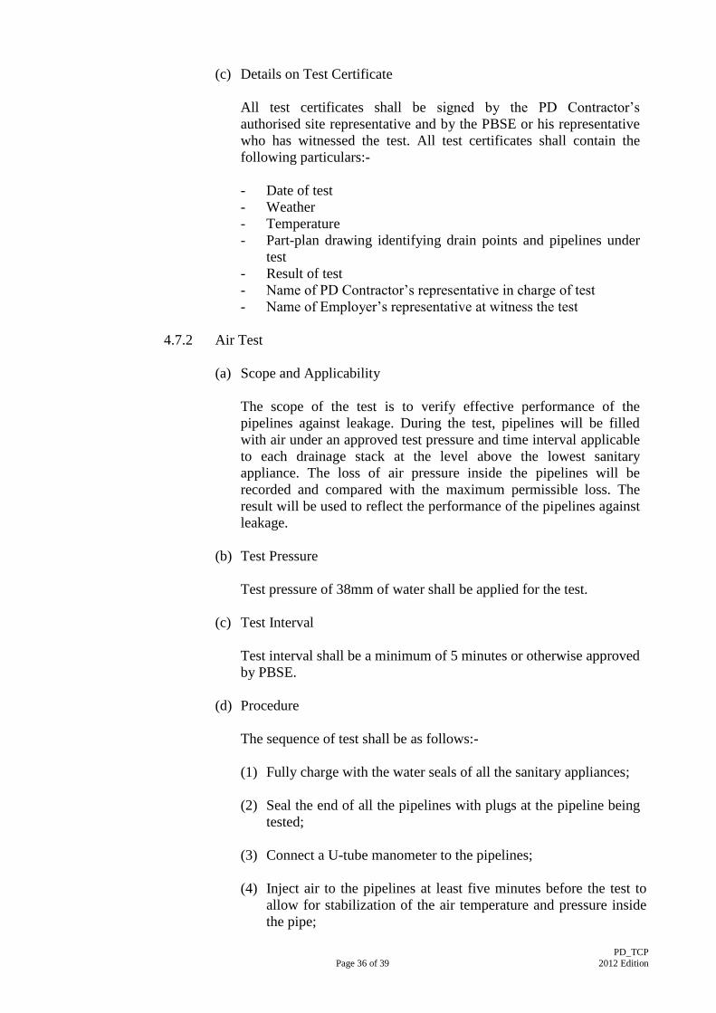
(c) Details on Test Certificate
All test certificates shall be signed by the PD Contractor’s
authorised site representative and by the PBSE or his representative
who has witnessed the test. All test certificates shall contain the
following particulars:-
- Date of test
- Weather
- Temperature
- Part-plan drawing identifying drain points and pipelines under
test
- Result of test
- Name of PD Contractor’s representative in charge of test
- Name of Employer’s representative at witness the test
4.7.2 Air Test
(a) Scope and Applicability
The scope of the test is to verify effective performance of the
pipelines against leakage. During the test, pipelines will be filled
with air under an approved test pressure and time interval applicable
to each drainage stack at the level above the lowest sanitary
appliance. The loss of air pressure inside the pipelines will be
recorded and compared with the maximum permissible loss. The
result will be used to reflect the performance of the pipelines against
leakage.
(b) Test Pressure
Test pressure of 38mm of water shall be applied for the test.
(c) Test Interval
Test interval shall be a minimum of 5 minutes or otherwise approved
by PBSE.
(d) Procedure
The sequence of test shall be as follows:-
(1) Fully charge with the water seals of all the sanitary appliances;
(2) Seal the end of all the pipelines with plugs at the pipeline being
tested;
(3) Connect a U-tube manometer to the pipelines;
(4) Inject air to the pipelines at least five minutes before the test to
allow for stabilization of the air temperature and pressure inside
the pipe;
PD_TCP
Page 37 of 39 2012 Edition
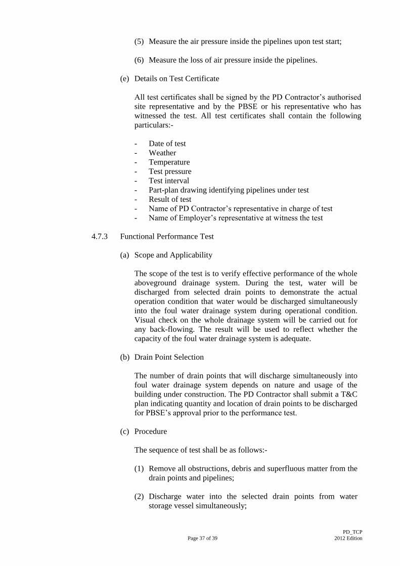
(5) Measure the air pressure inside the pipelines upon test start;
(6) Measure the loss of air pressure inside the pipelines.
(e) Details on Test Certificate
All test certificates shall be signed by the PD Contractor’s authorised
site representative and by the PBSE or his representative who has
witnessed the test. All test certificates shall contain the following
particulars:-
- Date of test
- Weather
- Temperature
- Test pressure
- Test interval
- Part-plan drawing identifying pipelines under test
- Result of test
- Name of PD Contractor’s representative in charge of test
- Name of Employer’s representative at witness the test
4.7.3 Functional Performance Test
(a) Scope and Applicability
The scope of the test is to verify effective performance of the whole
aboveground drainage system. During the test, water will be
discharged from selected drain points to demonstrate the actual
operation condition that water would be discharged simultaneously
into the foul water drainage system during operational condition.
Visual check on the whole drainage system will be carried out for
any back-flowing. The result will be used to reflect whether the
capacity of the foul water drainage system is adequate.
(b) Drain Point Selection
The number of drain points that will discharge simultaneously into
foul water drainage system depends on nature and usage of the
building under construction. The PD Contractor shall submit a T&C
plan indicating quantity and location of drain points to be discharged
for PBSE’s approval prior to the performance test.
(c) Procedure
The sequence of test shall be as follows:-
(1) Remove all obstructions, debris and superfluous matter from the
drain points and pipelines;
(2) Discharge water into the selected drain points from water
storage vessel simultaneously;
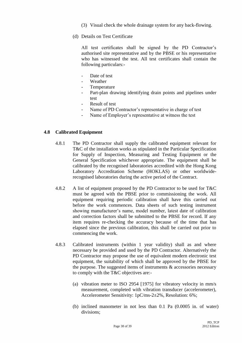
PD_TCP
Page 38 of 39 2012 Edition
(3) Visual check the whole drainage system for any back-flowing.
(d) Details on Test Certificate
All test certificates shall be signed by the PD Contractor’s
authorised site representative and by the PBSE or his representative
who has witnessed the test. All test certificates shall contain the
following particulars:-
- Date of test
- Weather
- Temperature
- Part-plan drawing identifying drain points and pipelines under
test
- Result of test
- Name of PD Contractor’s representative in charge of test
- Name of Employer’s representative at witness the test
4.8 Calibrated Equipment
4.8.1 The PD Contractor shall supply the calibrated equipment relevant for
T&C of the installation works as stipulated in the Particular Specification
for Supply of Inspection, Measuring and Testing Equipment or the
General Specification whichever appropriate. The equipment shall be
calibrated by the recognised laboratories accredited with the Hong Kong
Laboratory Accreditation Scheme (HOKLAS) or other worldwide-
recognised laboratories during the active period of the Contract.
4.8.2 A list of equipment proposed by the PD Contractor to be used for T&C
must be agreed with the PBSE prior to commissioning the work. All
equipment requiring periodic calibration shall have this carried out
before the work commences. Data sheets of such testing instrument
showing manufacturer’s name, model number, latest date of calibration
and correction factors shall be submitted to the PBSE for record. If any
item requires re-checking the accuracy because of the time that has
elapsed since the previous calibration, this shall be carried out prior to
commencing the work.
4.8.3 Calibrated instruments (within 1 year validity) shall as and where
necessary be provided and used by the PD Contractor. Alternatively the
PD Contractor may propose the use of equivalent modern electronic test
equipment, the suitability of which shall be approved by the PBSE for
the purpose. The suggested items of instruments & accessories necessary
to comply with the T&C objectives are:-
(a) vibration meter to ISO 2954 [1975] for vibratory velocity in mm/s
measurement, completed with vibration transducer (accelerometer),
Accelerometer Sensitivity: 1pC/ms-2±2%, Resolution: 6%;
(b) inclined manometer in not less than 0.1 Pa (0.0005 in. of water)
divisions;

PD_TCP
Page 39 of 39 2012 Edition
(c) combined inclined and vertical manometer 0-2000 Pa (0-10 in. of
water);
(d) pitot tubes (size 450 mm (18-in.) and 1200 mm (48-in.) long tube);
(e) a tachometer, which shall be the high quality, direct contact, self-
timing type;
(f) clamp-on ampere meter with voltage scales;
(g) pressure gauges (Manifold & Single);
(h) dial push/pull pressure gauge.

Annex I
Architectural Services Department Annex I Issue Date:- 8 August 2012 BSB - Standard Form No. Page 1 of 3 Revision Date:-
PBS/SR.077(2012) PD_TCP 2012 Edition
Testing and Commissioning Progress Chart
“Plumbing and Drainage Installation”
Flow Chart for T&C Procedure
START
(C) Submission of T&C
Programme by PD Contractor
Approval by PBSE
Approval by PBSE
Approval by PBSE
(A) & (B) & (C) Yes
Request for inspection (RFI) shall be submitted by PD Contractor
when the installation is completed. (Installed material / equipment
shall be approved.)
Inspection Passed
T &C Passed
Certification of Substantial Completion
-necessary T&C works shall be completed.
(refer to B.S.B. Instruction No. 4 of 2003)
END
(B) Submission of T&C
procedure by PD Contractor
(A) Submission of T&C
equipment c/w calibration
records by PD Contractor
Request for witness (RFWT) shall be submitted by PD Contractor
(T&C to be carried out by PD Contractor and draft record to be
attached with the relevant RFWT.)
T&C works
- witness by PBSE & Project Site Staff. (benchmarks on % of
witness to be refer to B.S.B. Instruction No. 5 &5A of 2000)
(D) T&C progress report
- shall be submitted by PD Contractor.
- shall be up-dated & checked by Project Site Staff
(E) T&C Certificate and test record
- formal certificate and record shall be submitted within adequate
time and signed by PBSE/Project Site Staff.
Y Y Y
N N N
N
Y
Y
N
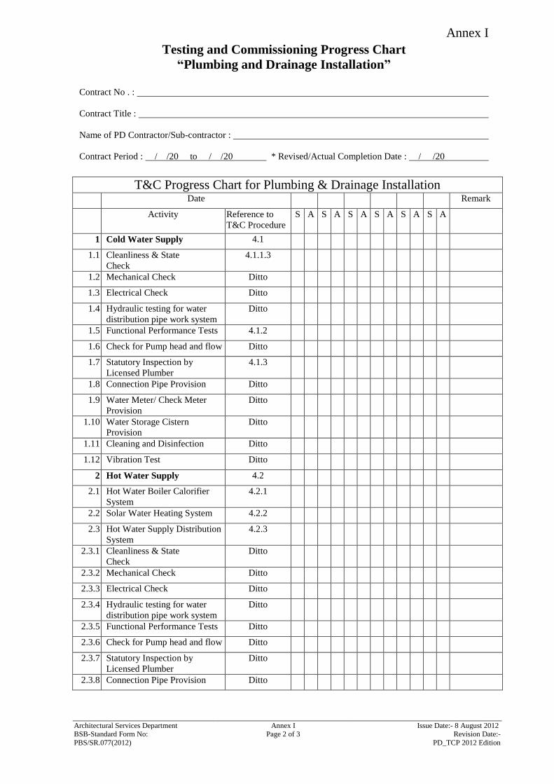
Annex I
Architectural Services Department Annex I Issue Date:- 8 August 2012 BSB-Standard Form No: Page 2 of 3 Revision Date:-
PBS/SR.077(2012) PD_TCP 2012 Edition
Testing and Commissioning Progress Chart
“Plumbing and Drainage Installation”
Contract No . :
Contract Title :
Name of PD Contractor/Sub-contractor :
Contract Period : / /20 to / /20 * Revised/Actual Completion Date : / /20
T&C Progress Chart for Plumbing & Drainage Installation
Date Remark
Activity Reference to
T&C Procedure
S A S A S A S A S A S A
1 Cold Water Supply 4.1
1.1 Cleanliness & State
Check
4.1.1.3
1.2 Mechanical Check Ditto
1.3 Electrical Check Ditto
1.4 Hydraulic testing for water
distribution pipe work system
Ditto
1.5 Functional Performance Tests 4.1.2
1.6 Check for Pump head and flow Ditto
1.7 Statutory Inspection by
Licensed Plumber
4.1.3
1.8 Connection Pipe Provision Ditto
1.9 Water Meter/ Check Meter
Provision
Ditto
1.10 Water Storage Cistern
Provision
Ditto
1.11 Cleaning and Disinfection Ditto
1.12 Vibration Test Ditto
2 Hot Water Supply 4.2
2.1 Hot Water Boiler Calorifier
System
4.2.1
2.2 Solar Water Heating System 4.2.2
2.3 Hot Water Supply Distribution
System
4.2.3
2.3.1 Cleanliness & State
Check
Ditto
2.3.2 Mechanical Check Ditto
2.3.3 Electrical Check Ditto
2.3.4 Hydraulic testing for water
distribution pipe work system
Ditto
2.3.5 Functional Performance Tests Ditto
2.3.6 Check for Pump head and flow Ditto
2.3.7 Statutory Inspection by
Licensed Plumber
Ditto
2.3.8 Connection Pipe Provision Ditto
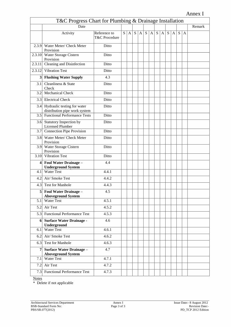
Annex I
Architectural Services Department Annex I Issue Date:- 8 August 2012 BSB-Standard Form No: Page 3 of 3 Revision Date:-
PBS/SR.077(2012) PD_TCP 2012 Edition
T&C Progress Chart for Plumbing & Drainage Installation
Date Remark
Activity Reference to
T&C Procedure
S A S A S A S A S A S A
2.3.9 Water Meter/ Check Meter
Provision
Ditto
2.3.10 Water Storage Cistern
Provision
Ditto
2.3.11 Cleaning and Disinfection Ditto
2.3.12 Vibration Test Ditto
3 Flushing Water Supply 4.3
3.1 Cleanliness & State
Check
Ditto
3.2 Mechanical Check Ditto
3.3 Electrical Check Ditto
3.4 Hydraulic testing for water
distribution pipe work system
Ditto
3.5 Functional Performance Tests Ditto
3.6 Statutory Inspection by
Licensed Plumber
Ditto
3.7 Connection Pipe Provision Ditto
3.8 Water Meter/ Check Meter
Provision
Ditto
3.9 Water Storage Cistern
Provision
Ditto
3.10 Vibration Test Ditto
4 Foul Water Drainage –
Underground System
4.4
4.1 Water Test 4.4.1
4.2 Air/ Smoke Test 4.4.2
4.3 Test for Manhole 4.4.3
5 Foul Water Drainage –
Aboveground System
4.5
5.1 Water Test 4.5.1
5.2 Air Test 4.5.2
5.3 Functional Performance Test 4.5.3
6 Surface Water Drainage -
Underground
4.6
6.1 Water Test 4.6.1
6.2 Air/ Smoke Test 4.6.2
6.3 Test for Manhole 4.6.3
7 Surface Water Drainage –
Aboveground System
4.7
7.1 Water Test 4.7.1
7.2 Air Test 4.7.2
7.3 Functional Performance Test 4.7.3
Notes
* Delete if not applicable
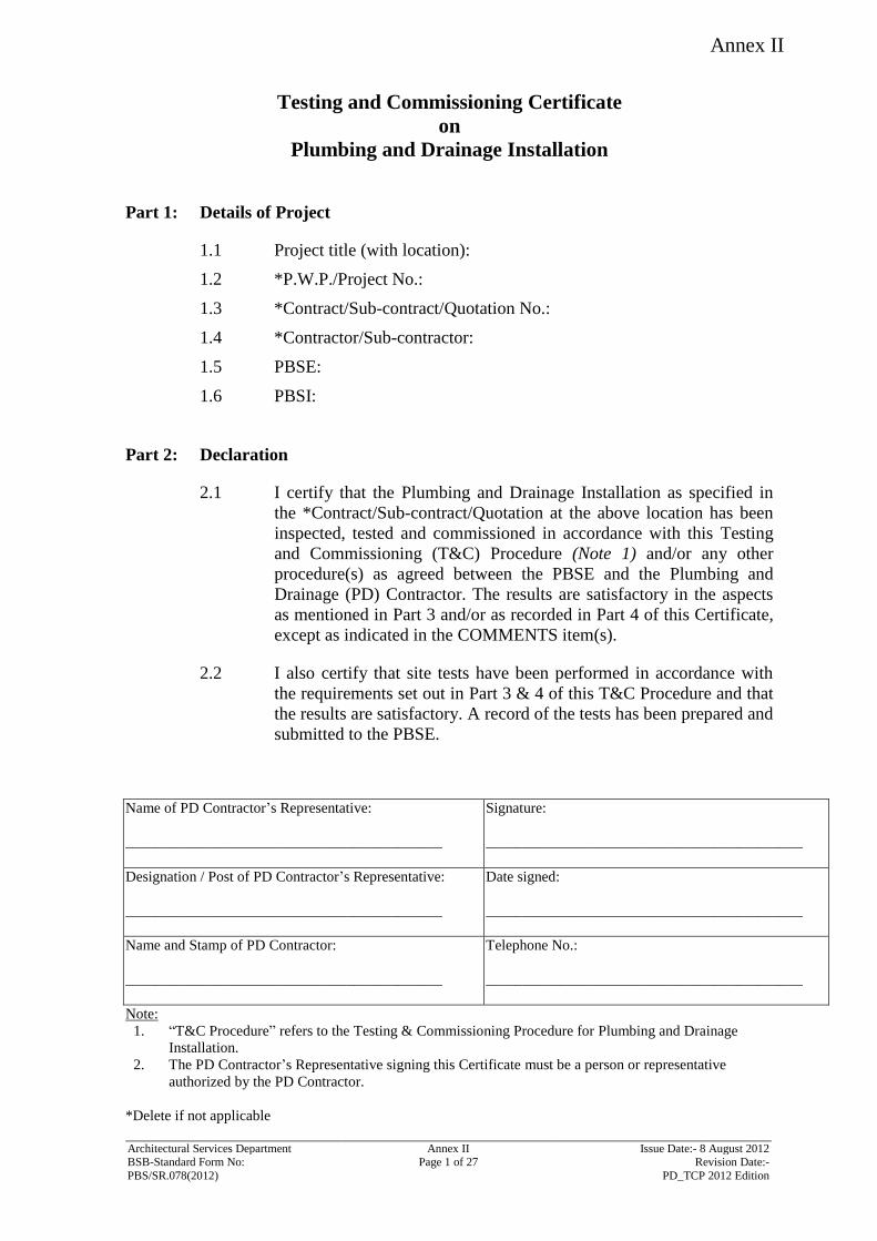
Annex II
Name of PD Contractor’s Representative:
___________________________________________
Signature:
___________________________________________
Designation / Post of PD Contractor’s Representative:
___________________________________________
Date signed:
___________________________________________
Name and Stamp of PD Contractor:
___________________________________________
Telephone No.:
___________________________________________
Note:
1. “T&C Procedure” refers to the Testing & Commissioning Procedure for Plumbing and Drainage
Installation.
2. The PD Contractor’s Representative signing this Certificate must be a person or representative
authorized by the PD Contractor.
*Delete if not applicable
Architectural Services Department Annex II Issue Date:- 8 August 2012 BSB-Standard Form No: Page 1 of 27 Revision Date:-
PBS/SR.078(2012) PD_TCP 2012 Edition
Testing and Commissioning Certificate
on
Plumbing and Drainage Installation
Part 1: Details of Project
1.1 Project title (with location):
1.2 *P.W.P./Project No.:
1.3 *Contract/Sub-contract/Quotation No.:
1.4 *Contractor/Sub-contractor:
1.5 PBSE:
1.6 PBSI:
Part 2: Declaration
2.1 I certify that the Plumbing and Drainage Installation as specified in
the *Contract/Sub-contract/Quotation at the above location has been
inspected, tested and commissioned in accordance with this Testing
and Commissioning (T&C) Procedure (Note 1) and/or any other
procedure(s) as agreed between the PBSE and the Plumbing and
Drainage (PD) Contractor. The results are satisfactory in the aspects
as mentioned in Part 3 and/or as recorded in Part 4 of this Certificate,
except as indicated in the COMMENTS item(s).
2.2 I also certify that site tests have been performed in accordance with
the requirements set out in Part 3 & 4 of this T&C Procedure and that
the results are satisfactory. A record of the tests has been prepared and
submitted to the PBSE.
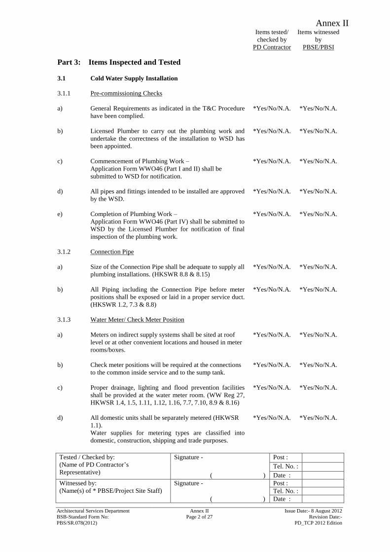
Annex II
Items tested/
checked by
PD Contractor
Items witnessed
by
PBSE/PBSI
Tested / Checked by:
(Name of PD Contractor’s
Representative)
Signature - Post :
Tel. No. :
( ) Date :
Witnessed by:
(Name(s) of * PBSE/Project Site Staff)
Signature - Post :
Tel. No. :
( ) Date :
Architectural Services Department Annex II Issue Date:- 8 August 2012 BSB-Standard Form No: Page 2 of 27 Revision Date:-
PBS/SR.078(2012) PD_TCP 2012 Edition
Part 3: Items Inspected and Tested
3.1
Cold Water Supply Installation
3.1.1
Pre-commissioning Checks
a)
General Requirements as indicated in the T&C Procedure
have been complied.
*Yes/No/N.A. *Yes/No/N.A.
b) Licensed Plumber to carry out the plumbing work and
undertake the correctness of the installation to WSD has
been appointed.
*Yes/No/N.A. *Yes/No/N.A.
c) Commencement of Plumbing Work –
Application Form WWO46 (Part I and II) shall be
submitted to WSD for notification.
*Yes/No/N.A. *Yes/No/N.A.
d) All pipes and fittings intended to be installed are approved
by the WSD.
*Yes/No/N.A. *Yes/No/N.A.
e) Completion of Plumbing Work –
Application Form WWO46 (Part IV) shall be submitted to
WSD by the Licensed Plumber for notification of final
inspection of the plumbing work.
*Yes/No/N.A. *Yes/No/N.A.
3.1.2 Connection Pipe
a) Size of the Connection Pipe shall be adequate to supply all
plumbing installations. (HKSWR 8.8 & 8.15)
*Yes/No/N.A. *Yes/No/N.A.
b) All Piping including the Connection Pipe before meter
positions shall be exposed or laid in a proper service duct.
(HKSWR 1.2, 7.3 & 8.8)
*Yes/No/N.A. *Yes/No/N.A.
3.1.3 Water Meter/ Check Meter Position
a) Meters on indirect supply systems shall be sited at roof
level or at other convenient locations and housed in meter
rooms/boxes.
*Yes/No/N.A. *Yes/No/N.A.
b) Check meter positions will be required at the connections
to the common inside service and to the sump tank.
*Yes/No/N.A. *Yes/No/N.A.
c) Proper drainage, lighting and flood prevention facilities
shall be provided at the water meter room. (WW Reg 27,
HKWSR 1.4, 1.5, 1.11, 1.12, 1.16, 7.7, 7.10, 8.9 & 8.16)
*Yes/No/N.A. *Yes/No/N.A.
d) All domestic units shall be separately metered (HKWSR
1.1).
*Yes/No/N.A. *Yes/No/N.A.
Water supplies for metering types are classified into
domestic, construction, shipping and trade purposes.
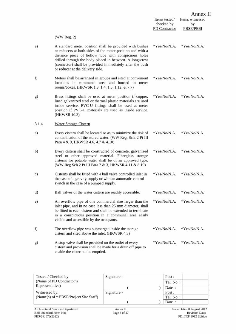
Annex II
Items tested/
checked by
PD Contractor
Items witnessed
by
PBSE/PBSI
Tested / Checked by:
(Name of PD Contractor’s
Representative)
Signature - Post :
Tel. No. :
( ) Date :
Witnessed by:
(Name(s) of * PBSE/Project Site Staff)
Signature - Post :
Tel. No. :
( ) Date :
Architectural Services Department Annex II Issue Date:- 8 August 2012 BSB-Standard Form No: Page 3 of 27 Revision Date:-
PBS/SR.078(2012) PD_TCP 2012 Edition
(WW Reg. 2)
e) A standard meter position shall be provided with bushes
or reducers at both sides of the meter position and with a
distance piece of hollow tube with conspicuous holes
drilled through the body placed in between. A longscrew
(connector) shall be provided immediately after the bush
or reducer at the delivery side.
*Yes/No/N.A. *Yes/No/N.A.
f) Meters shall be arranged in groups and sited at convenient
locations in communal area and housed in meter
rooms/boxes. (HKWSR 1.3, 1.4, 1.5, 1.12, & 7.7)
*Yes/No/N.A. *Yes/No/N.A.
g) Brass fittings shall be used at meter position if copper,
lined galvanized steel or thermal plastic materials are used
inside service. PVC-U fittings shall be used at meter
position if PVC-U materials are used as inside service.
(HKWSR 10.3)
*Yes/No/N.A. *Yes/No/N.A.
3.1.4 Water Storage Cistern
a) Every cistern shall be located so as to minimize the risk of
contamination of the stored water. (WW Reg. Sch. 2 Pt III
Para 4 & 9, HKWSR 4.6, 4.7 & 4.10)
*Yes/No/N.A. *Yes/No/N.A.
b) Every cistern shall be constructed of concrete, galvanized
steel or other approved material. Fibreglass storage
cisterns for potable water shall be of an approved type.
(WW Reg Sch 2 Pt III Para 2 & 3, HKWSR 4.11 & 8.19)
*Yes/No/N.A. *Yes/No/N.A.
c) Cisterns shall be fitted with a ball valve controlled inlet in
the case of a gravity supply or with an automatic control
switch in the case of a pumped supply.
*Yes/No/N.A. *Yes/No/N.A.
d) Ball valves of the water cistern are readily accessible. *Yes/No/N.A. *Yes/No/N.A.
e) An overflow pipe of one commercial size larger than the
inlet pipe, and in no case less than 25 mm diameter, shall
be fitted to each cistern and shall be extended to terminate
in a conspicuous position in a communal area easily
visible and accessible by the occupants.
*Yes/No/N.A. *Yes/No/N.A.
f) The overflow pipe was submerged inside the storage
cistern and sited above the inlet. (HKWSR 4.3)
*Yes/No/N.A. *Yes/No/N.A.
g) A stop valve shall be provided on the outlet of every
cistern and provision shall be made for a drain off pipe to
enable the cistern to be emptied.
*Yes/No/N.A. *Yes/No/N.A.
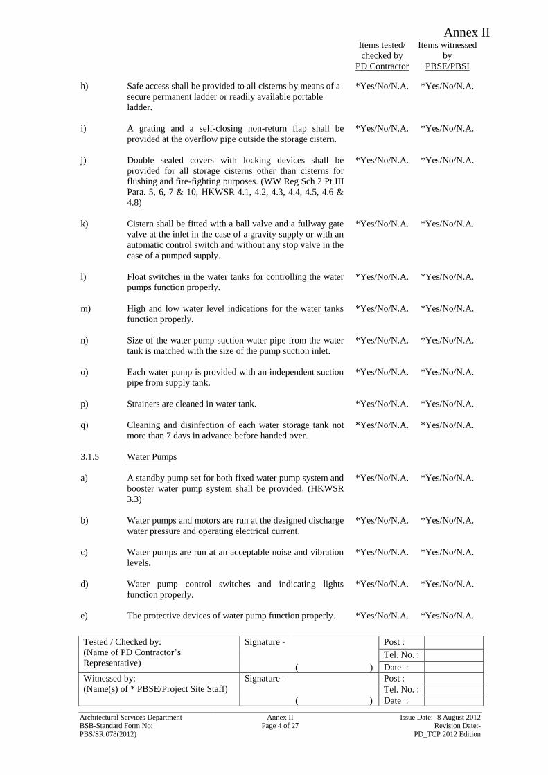
Annex II
Items tested/
checked by
PD Contractor
Items witnessed
by
PBSE/PBSI
Tested / Checked by:
(Name of PD Contractor’s
Representative)
Signature - Post :
Tel. No. :
( ) Date :
Witnessed by:
(Name(s) of * PBSE/Project Site Staff)
Signature - Post :
Tel. No. :
( ) Date :
Architectural Services Department Annex II Issue Date:- 8 August 2012 BSB-Standard Form No: Page 4 of 27 Revision Date:-
PBS/SR.078(2012) PD_TCP 2012 Edition
h) Safe access shall be provided to all cisterns by means of a
secure permanent ladder or readily available portable
ladder.
*Yes/No/N.A. *Yes/No/N.A.
i) A grating and a self-closing non-return flap shall be
provided at the overflow pipe outside the storage cistern.
*Yes/No/N.A. *Yes/No/N.A.
j) Double sealed covers with locking devices shall be
provided for all storage cisterns other than cisterns for
flushing and fire-fighting purposes. (WW Reg Sch 2 Pt III
Para. 5, 6, 7 & 10, HKWSR 4.1, 4.2, 4.3, 4.4, 4.5, 4.6 &
4.8)
*Yes/No/N.A. *Yes/No/N.A.
k) Cistern shall be fitted with a ball valve and a fullway gate
valve at the inlet in the case of a gravity supply or with an
automatic control switch and without any stop valve in the
case of a pumped supply.
*Yes/No/N.A. *Yes/No/N.A.
l) Float switches in the water tanks for controlling the water
pumps function properly.
*Yes/No/N.A. *Yes/No/N.A.
m) High and low water level indications for the water tanks
function properly.
*Yes/No/N.A. *Yes/No/N.A.
n) Size of the water pump suction water pipe from the water
tank is matched with the size of the pump suction inlet.
*Yes/No/N.A. *Yes/No/N.A.
o) Each water pump is provided with an independent suction
pipe from supply tank.
*Yes/No/N.A. *Yes/No/N.A.
p) Strainers are cleaned in water tank. *Yes/No/N.A. *Yes/No/N.A.
q) Cleaning and disinfection of each water storage tank not
more than 7 days in advance before handed over.
*Yes/No/N.A. *Yes/No/N.A.
3.1.5 Water Pumps
a) A standby pump set for both fixed water pump system and
booster water pump system shall be provided. (HKWSR
3.3)
*Yes/No/N.A. *Yes/No/N.A.
b) Water pumps and motors are run at the designed discharge
water pressure and operating electrical current.
*Yes/No/N.A. *Yes/No/N.A.
c) Water pumps are run at an acceptable noise and vibration
levels.
*Yes/No/N.A. *Yes/No/N.A.
d) Water pump control switches and indicating lights
function properly.
*Yes/No/N.A. *Yes/No/N.A.
e) The protective devices of water pump function properly. *Yes/No/N.A. *Yes/No/N.A.
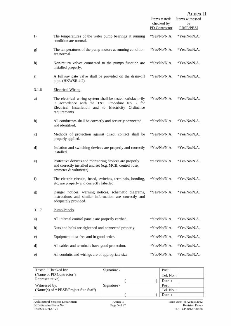
Annex II
Items tested/
checked by
PD Contractor
Items witnessed
by
PBSE/PBSI
Tested / Checked by:
(Name of PD Contractor’s
Representative)
Signature - Post :
Tel. No. :
( ) Date :
Witnessed by:
(Name(s) of * PBSE/Project Site Staff)
Signature - Post :
Tel. No. :
( ) Date :
Architectural Services Department Annex II Issue Date:- 8 August 2012 BSB-Standard Form No: Page 5 of 27 Revision Date:-
PBS/SR.078(2012) PD_TCP 2012 Edition
f) The temperatures of the water pump bearings at running
condition are normal.
*Yes/No/N.A. *Yes/No/N.A.
g) The temperatures of the pump motors at running condition
are normal.
*Yes/No/N.A. *Yes/No/N.A.
h) Non-return valves connected to the pumps function are
installed properly.
*Yes/No/N.A. *Yes/No/N.A.
i) A fullway gate valve shall be provided on the drain-off
pipe. (HKWSR 4.2)
*Yes/No/N.A. *Yes/No/N.A.
3.1.6 Electrical Wiring
a) The electrical wiring system shall be tested satisfactorily
in accordance with the T&C Procedure No. 2 for
Electrical Installation and to Electricity Ordinance
requirements.
*Yes/No/N.A. *Yes/No/N.A.
b) All conductors shall be correctly and securely connected
and identified.
*Yes/No/N.A. *Yes/No/N.A.
c) Methods of protection against direct contact shall be
properly applied.
*Yes/No/N.A. *Yes/No/N.A.
d) Isolation and switching devices are properly and correctly
installed.
*Yes/No/N.A. *Yes/No/N.A.
e) Protective devices and monitoring devices are properly
and correctly installed and set (e.g. MCB, control fuse,
ammeter & voltmeter).
*Yes/No/N.A. *Yes/No/N.A.
f) The electric circuits, fused, switches, terminals, bonding,
etc. are properly and correctly labelled.
*Yes/No/N.A. *Yes/No/N.A.
g) Danger notices, warning notices, schematic diagrams,
instructions and similar information are correctly and
adequately provided.
*Yes/No/N.A. *Yes/No/N.A.
3.1.7 Pump Panels
a) All internal control panels are properly earthed. *Yes/No/N.A. *Yes/No/N.A.
b) Nuts and bolts are tightened and connected properly. *Yes/No/N.A. *Yes/No/N.A.
c) Equipment dust-free and in good order. *Yes/No/N.A. *Yes/No/N.A.
d) All cables and terminals have good protection. *Yes/No/N.A. *Yes/No/N.A.
e) All conduits and wirings are of appropriate size. *Yes/No/N.A. *Yes/No/N.A.
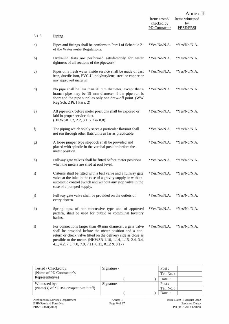
Annex II
Items tested/
checked by
PD Contractor
Items witnessed
by
PBSE/PBSI
Tested / Checked by:
(Name of PD Contractor’s
Representative)
Signature - Post :
Tel. No. :
( ) Date :
Witnessed by:
(Name(s) of * PBSE/Project Site Staff)
Signature - Post :
Tel. No. :
( ) Date :
Architectural Services Department Annex II Issue Date:- 8 August 2012 BSB-Standard Form No: Page 6 of 27 Revision Date:-
PBS/SR.078(2012) PD_TCP 2012 Edition
3.1.8 Piping
a) Pipes and fittings shall be conform to Part I of Schedule 2
of the Waterworks Regulations.
*Yes/No/N.A. *Yes/No/N.A.
b) Hydraulic tests are performed satisfactorily for water
tightness of all sections of the pipework.
*Yes/No/N.A. *Yes/No/N.A.
c) Pipes on a fresh water inside service shall be made of cast
iron, ductile iron, PVC-U, polybutylene, steel or copper or
any approved material.
*Yes/No/N.A. *Yes/No/N.A.
d) No pipe shall be less than 20 mm diameter, except that a
branch pipe may be 15 mm diameter if the pipe run is
short and the pipe supplies only one draw-off point. (WW
Reg Sch. 2 Pt. I Para. 2)
*Yes/No/N.A. *Yes/No/N.A.
e) All pipework before meter positions shall be exposed or
laid in proper service duct.
(HKWSR 1.2, 2.2, 3.1, 7.3 & 8.8)
*Yes/No/N.A. *Yes/No/N.A.
f) The piping which solely serve a particular flat/unit shall
not run through other flats/units as far as practicable.
*Yes/No/N.A. *Yes/No/N.A.
g) A loose jumper type stopcock shall be provided and
placed with spindle in the vertical position before the
meter position.
*Yes/No/N.A. *Yes/No/N.A.
h) Fullway gate valves shall be fitted before meter positions
when the meters are sited at roof level.
*Yes/No/N.A. *Yes/No/N.A.
i) Cisterns shall be fitted with a ball valve and a fullway gate
valve at the inlet in the case of a gravity supply or with an
automatic control switch and without any stop valve in the
case of a pumped supply.
*Yes/No/N.A. *Yes/No/N.A.
j) Fullway gate valve shall be provided on the outlets of
every cistern.
*Yes/No/N.A. *Yes/No/N.A.
k) Spring taps, of non-concussive type and of approved
pattern, shall be used for public or communal lavatory
basins.
*Yes/No/N.A. *Yes/No/N.A.
l) For connections larger than 40 mm diameter, a gate valve
shall be provided before the meter position and a non-
return or check valve fitted on the delivery side as close as
possible to the meter. (HKWSR 1.10, 1.14, 1.15, 2.4, 3.4,
4.1, 4.2, 7.5, 7.8, 7.9, 7.11, 8.11, 8.12 & 8.17)
*Yes/No/N.A. *Yes/No/N.A.
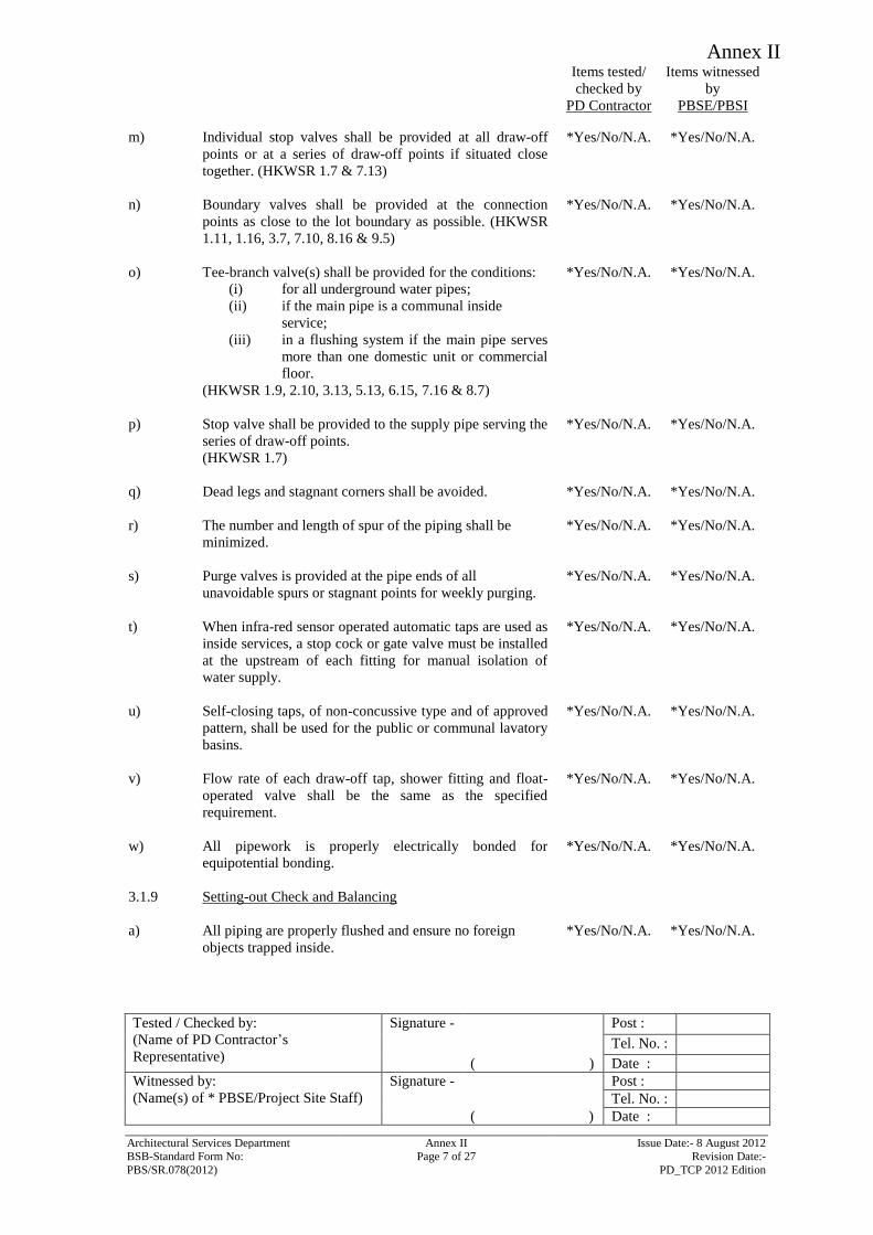
Annex II
Items tested/
checked by
PD Contractor
Items witnessed
by
PBSE/PBSI
Tested / Checked by:
(Name of PD Contractor’s
Representative)
Signature - Post :
Tel. No. :
( ) Date :
Witnessed by:
(Name(s) of * PBSE/Project Site Staff)
Signature - Post :
Tel. No. :
( ) Date :
Architectural Services Department Annex II Issue Date:- 8 August 2012 BSB-Standard Form No: Page 7 of 27 Revision Date:-
PBS/SR.078(2012) PD_TCP 2012 Edition
m) Individual stop valves shall be provided at all draw-off
points or at a series of draw-off points if situated close
together. (HKWSR 1.7 & 7.13)
*Yes/No/N.A. *Yes/No/N.A.
n) Boundary valves shall be provided at the connection
points as close to the lot boundary as possible. (HKWSR
1.11, 1.16, 3.7, 7.10, 8.16 & 9.5)
*Yes/No/N.A. *Yes/No/N.A.
o) Tee-branch valve(s) shall be provided for the conditions:
(i) for all underground water pipes;
(ii) if the main pipe is a communal inside
service;
(iii) in a flushing system if the main pipe serves
more than one domestic unit or commercial
floor.
(HKWSR 1.9, 2.10, 3.13, 5.13, 6.15, 7.16 & 8.7)
*Yes/No/N.A. *Yes/No/N.A.
p) Stop valve shall be provided to the supply pipe serving the
series of draw-off points.
(HKWSR 1.7)
*Yes/No/N.A. *Yes/No/N.A.
q) Dead legs and stagnant corners shall be avoided. *Yes/No/N.A. *Yes/No/N.A.
r) The number and length of spur of the piping shall be
minimized.
*Yes/No/N.A. *Yes/No/N.A.
s) Purge valves is provided at the pipe ends of all
unavoidable spurs or stagnant points for weekly purging.
*Yes/No/N.A. *Yes/No/N.A.
t) When infra-red sensor operated automatic taps are used as
inside services, a stop cock or gate valve must be installed
at the upstream of each fitting for manual isolation of
water supply.
*Yes/No/N.A. *Yes/No/N.A.
u) Self-closing taps, of non-concussive type and of approved
pattern, shall be used for the public or communal lavatory
basins.
*Yes/No/N.A. *Yes/No/N.A.
v) Flow rate of each draw-off tap, shower fitting and float-
operated valve shall be the same as the specified
requirement.
*Yes/No/N.A. *Yes/No/N.A.
w) All pipework is properly electrically bonded for
equipotential bonding.
*Yes/No/N.A. *Yes/No/N.A.
3.1.9 Setting-out Check and Balancing
a) All piping are properly flushed and ensure no foreign
objects trapped inside.
*Yes/No/N.A. *Yes/No/N.A.
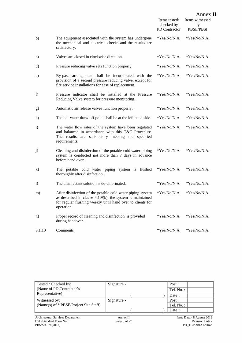
Annex II
Items tested/
checked by
PD Contractor
Items witnessed
by
PBSE/PBSI
Tested / Checked by:
(Name of PD Contractor’s
Representative)
Signature - Post :
Tel. No. :
( ) Date :
Witnessed by:
(Name(s) of * PBSE/Project Site Staff)
Signature - Post :
Tel. No. :
( ) Date :
Architectural Services Department Annex II Issue Date:- 8 August 2012 BSB-Standard Form No: Page 8 of 27 Revision Date:-
PBS/SR.078(2012) PD_TCP 2012 Edition
b) The equipment associated with the system has undergone
the mechanical and electrical checks and the results are
satisfactory.
*Yes/No/N.A. *Yes/No/N.A.
c) Valves are closed in clockwise direction. *Yes/No/N.A. *Yes/No/N.A.
d) Pressure reducing valve sets function properly. *Yes/No/N.A. *Yes/No/N.A.
e) By-pass arrangement shall be incorporated with the
provision of a second pressure reducing valve, except for
fire service installations for ease of replacement.
*Yes/No/N.A. *Yes/No/N.A.
f) Pressure indicator shall be installed at the Pressure
Reducing Valve system for pressure monitoring.
*Yes/No/N.A. *Yes/No/N.A.
g) Automatic air release valves function properly. *Yes/No/N.A. *Yes/No/N.A.
h) The hot-water draw-off point shall be at the left hand side. *Yes/No/N.A. *Yes/No/N.A.
i) The water flow rates of the system have been regulated
and balanced in accordance with this T&C Procedure.
The results are satisfactory meeting the specified
requirements.
*Yes/No/N.A. *Yes/No/N.A.
j) Cleaning and disinfection of the potable cold water piping
system is conducted not more than 7 days in advance
before hand over.
*Yes/No/N.A. *Yes/No/N.A.
k) The potable cold water piping system is flushed
thoroughly after disinfection.
*Yes/No/N.A. *Yes/No/N.A.
l) The disinfectant solution is de-chlorinated. *Yes/No/N.A. *Yes/No/N.A.
m) After disinfection of the potable cold water piping system
as described in clause 3.1.9(k), the system is maintained
for regular flushing weekly until hand over to clients for
operation.
*Yes/No/N.A. *Yes/No/N.A.
n) Proper record of cleaning and disinfection is provided
during handover.
*Yes/No/N.A. *Yes/No/N.A.
3.1.10 Comments *Yes/No/N.A. *Yes/No/N.A.
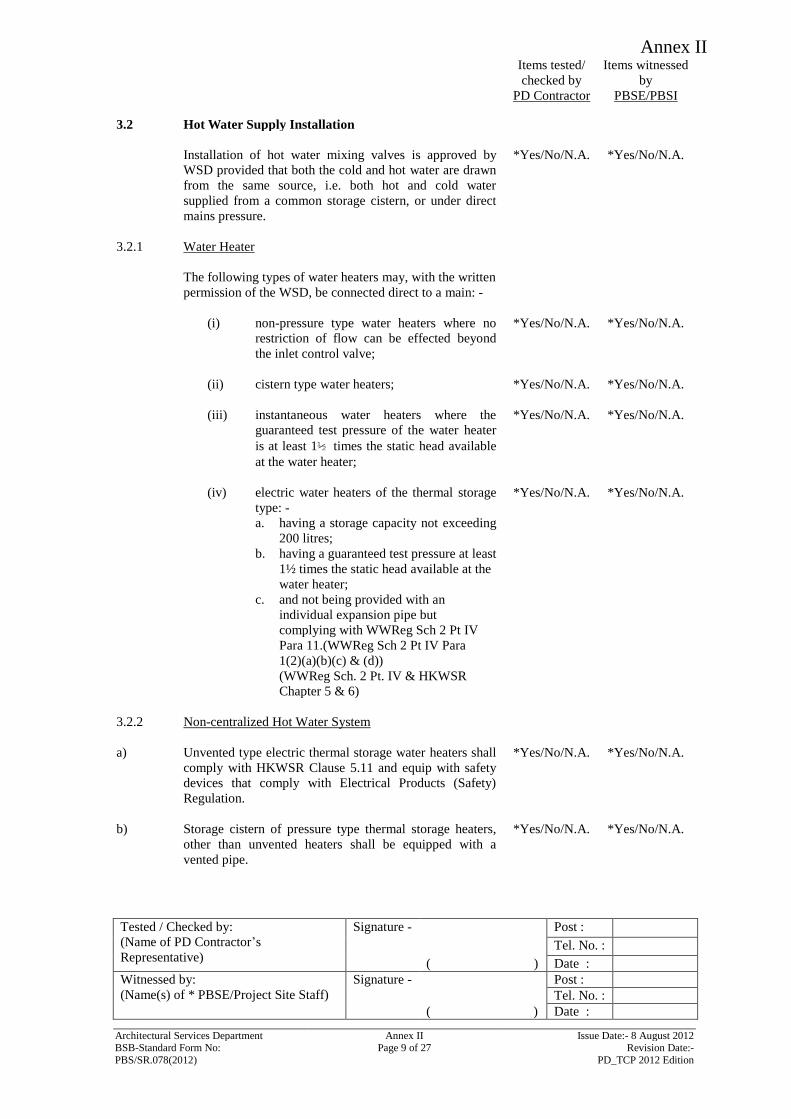
Annex II
Items tested/
checked by
PD Contractor
Items witnessed
by
PBSE/PBSI
Tested / Checked by:
(Name of PD Contractor’s
Representative)
Signature - Post :
Tel. No. :
( ) Date :
Witnessed by:
(Name(s) of * PBSE/Project Site Staff)
Signature - Post :
Tel. No. :
( ) Date :
Architectural Services Department Annex II Issue Date:- 8 August 2012 BSB-Standard Form No: Page 9 of 27 Revision Date:-
PBS/SR.078(2012) PD_TCP 2012 Edition
3.2 Hot Water Supply Installation
Installation of hot water mixing valves is approved by
WSD provided that both the cold and hot water are drawn
from the same source, i.e. both hot and cold water
supplied from a common storage cistern, or under direct
mains pressure.
*Yes/No/N.A. *Yes/No/N.A.
3.2.1 Water Heater
The following types of water heaters may, with the written
permission of the WSD, be connected direct to a main: -
(i) non-pressure type water heaters where no
restriction of flow can be effected beyond
the inlet control valve;
*Yes/No/N.A. *Yes/No/N.A.
(ii) cistern type water heaters; *Yes/No/N.A. *Yes/No/N.A.
(iii) instantaneous water heaters where the
guaranteed test pressure of the water heater
is at least 1½ times the static head available
at the water heater;
*Yes/No/N.A. *Yes/No/N.A.
(iv) electric water heaters of the thermal storage
type: -
a. having a storage capacity not exceeding
200 litres;
b. having a guaranteed test pressure at least
1½ times the static head available at the
water heater;
c. and not being provided with an
individual expansion pipe but
complying with WWReg Sch 2 Pt IV
Para 11.(WWReg Sch 2 Pt IV Para
1(2)(a)(b)(c) & (d))
(WWReg Sch. 2 Pt. IV & HKWSR
Chapter 5 & 6)
*Yes/No/N.A. *Yes/No/N.A.
3.2.2 Non-centralized Hot Water System
a) Unvented type electric thermal storage water heaters shall
comply with HKWSR Clause 5.11 and equip with safety
devices that comply with Electrical Products (Safety)
Regulation.
*Yes/No/N.A. *Yes/No/N.A.
b) Storage cistern of pressure type thermal storage heaters,
other than unvented heaters shall be equipped with a
vented pipe.
*Yes/No/N.A. *Yes/No/N.A.
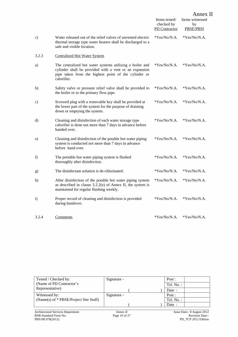
Annex II
Items tested/
checked by
PD Contractor
Items witnessed
by
PBSE/PBSI
Tested / Checked by:
(Name of PD Contractor’s
Representative)
Signature - Post :
Tel. No. :
( ) Date :
Witnessed by:
(Name(s) of * PBSE/Project Site Staff)
Signature - Post :
Tel. No. :
( ) Date :
Architectural Services Department Annex II Issue Date:- 8 August 2012 BSB-Standard Form No: Page 10 of 27 Revision Date:-
PBS/SR.078(2012) PD_TCP 2012 Edition
c) Water released out of the relief valves of unvented electric
thermal storage type water heaters shall be discharged to a
safe and visible location.
*Yes/No/N.A. *Yes/No/N.A.
3.2.3 Centralized Hot Water System
a) The centralized hot water systems utilizing a boiler and
cylinder shall be provided with a vent or an expansion
pipe taken from the highest point of the cylinder or
calorifier.
*Yes/No/N.A. *Yes/No/N.A.
b) Safety valve or pressure relief valve shall be provided to
the boiler or to the primary flow pipe.
*Yes/No/N.A. *Yes/No/N.A.
c) Screwed plug with a removable key shall be provided at
the lower part of the system for the purpose of draining
down or emptying the system.
*Yes/No/N.A. *Yes/No/N.A.
d) Cleaning and disinfection of each water storage type
calorifier is done not more than 7 days in advance before
handed over.
*Yes/No/N.A. *Yes/No/N.A.
e) Cleaning and disinfection of the potable hot water piping
system is conducted not more than 7 days in advance
before hand over.
*Yes/No/N.A. *Yes/No/N.A.
f) The portable hot water piping system is flushed
thoroughly after disinfection.
*Yes/No/N.A. *Yes/No/N.A.
g) The disinfectant solution is de-chlorinated. *Yes/No/N.A. *Yes/No/N.A.
h) After disinfection of the potable hot water piping system
as described in clause 3.2.2(e) of Annex II, the system is
maintained for regular flushing weekly.
*Yes/No/N.A. *Yes/No/N.A.
i) Proper record of cleaning and disinfection is provided
during handover.
*Yes/No/N.A. *Yes/No/N.A.
3.2.4 Comments *Yes/No/N.A. *Yes/No/N.A.
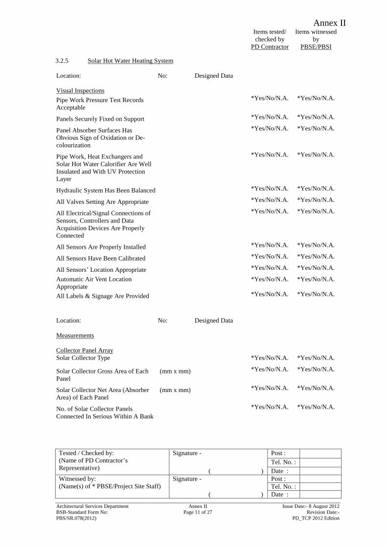
Annex II
Items tested/
checked by
PD Contractor
Items witnessed
by
PBSE/PBSI
Tested / Checked by:
(Name of PD Contractor’s
Representative)
Signature - Post :
Tel. No. :
( ) Date :
Witnessed by:
(Name(s) of * PBSE/Project Site Staff)
Signature - Post :
Tel. No. :
( ) Date :
Architectural Services Department Annex II Issue Date:- 8 August 2012 BSB-Standard Form No: Page 11 of 27 Revision Date:-
PBS/SR.078(2012) PD_TCP 2012 Edition
3.2.5 Solar Hot Water Heating System
Location: No: Designed Data
Visual Inspections
Pipe Work Pressure Test Records
Acceptable
*Yes/No/N.A. *Yes/No/N.A.
Panels Securely Fixed on Support *Yes/No/N.A. *Yes/No/N.A.
Panel Absorber Surfaces Has
Obvious Sign of Oxidation or De-
colourization
*Yes/No/N.A. *Yes/No/N.A.
Pipe Work, Heat Exchangers and
Solar Hot Water Calorifier Are Well
Insulated and With UV Protection
Layer
*Yes/No/N.A. *Yes/No/N.A.
Hydraulic System Has Been Balanced *Yes/No/N.A. *Yes/No/N.A.
All Valves Setting Are Appropriate *Yes/No/N.A. *Yes/No/N.A.
All Electrical/Signal Connections of
Sensors, Controllers and Data
Acquisition Devices Are Properly
Connected
*Yes/No/N.A. *Yes/No/N.A.
All Sensors Are Properly Installed *Yes/No/N.A. *Yes/No/N.A.
All Sensors Have Been Calibrated *Yes/No/N.A. *Yes/No/N.A.
All Sensors’ Location Appropriate *Yes/No/N.A. *Yes/No/N.A.
Automatic Air Vent Location
Appropriate *Yes/No/N.A. *Yes/No/N.A.
All Labels & Signage Are Provided *Yes/No/N.A. *Yes/No/N.A.
Location: No: Designed Data
Measurements
Collector Panel Array
Solar Collector Type *Yes/No/N.A. *Yes/No/N.A.
Solar Collector Gross Area of Each
Panel
(mm x mm) *Yes/No/N.A. *Yes/No/N.A.
Solar Collector Net Area (Absorber
Area) of Each Panel
(mm x mm) *Yes/No/N.A. *Yes/No/N.A.
No. of Solar Collector Panels
Connected In Serious Within A Bank
*Yes/No/N.A. *Yes/No/N.A.
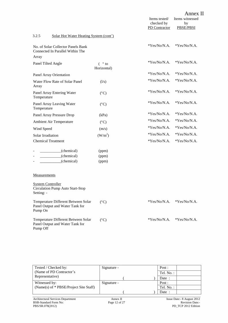
Annex II
Items tested/
checked by
PD Contractor
Items witnessed
by
PBSE/PBSI
Tested / Checked by:
(Name of PD Contractor’s
Representative)
Signature - Post :
Tel. No. :
( ) Date :
Witnessed by:
(Name(s) of * PBSE/Project Site Staff)
Signature - Post :
Tel. No. :
( ) Date :
Architectural Services Department Annex II Issue Date:- 8 August 2012 BSB-Standard Form No: Page 12 of 27 Revision Date:-
PBS/SR.078(2012) PD_TCP 2012 Edition
3.2.5 Solar Hot Water Heating System (cont’)
No. of Solar Collector Panels Bank
Connected In Parallel Within The
Array
*Yes/No/N.A. *Yes/No/N.A.
Panel Tilted Angle ( to
Horizontal)
*Yes/No/N.A. *Yes/No/N.A.
Panel Array Orientation *Yes/No/N.A. *Yes/No/N.A.
Water Flow Rate of Solar Panel
Array
(l/s) *Yes/No/N.A. *Yes/No/N.A.
Panel Array Entering Water
Temperature (C) *Yes/No/N.A. *Yes/No/N.A.
Panel Array Leaving Water
Temperature (C) *Yes/No/N.A. *Yes/No/N.A.
Panel Array Pressure Drop (kPa) *Yes/No/N.A. *Yes/No/N.A.
Ambient Air Temperature (C) *Yes/No/N.A. *Yes/No/N.A.
Wind Speed (m/s) *Yes/No/N.A. *Yes/No/N.A.
Solar Irradiation (W/m2) *Yes/No/N.A. *Yes/No/N.A.
Chemical Treatment
- ___________(chemical)
- ___________(chemical)
- ___________(chemical)
(ppm)
(ppm)
(ppm)
*Yes/No/N.A. *Yes/No/N.A.
Measurements
System Controller
Circulation Pump Auto Start-Stop
Setting: -
Temperature Different Between Solar
Panel Output and Water Tank for
Pump On
(C)
*Yes/No/N.A.
*Yes/No/N.A.
Temperature Different Between Solar
Panel Output and Water Tank for
Pump Off
(C) *Yes/No/N.A. *Yes/No/N.A.
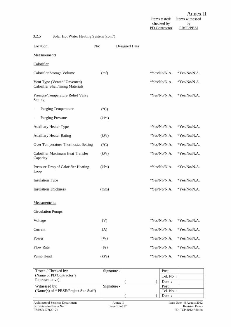
Annex II
Items tested/
checked by
PD Contractor
Items witnessed
by
PBSE/PBSI
Tested / Checked by:
(Name of PD Contractor’s
Representative)
Signature - Post :
Tel. No. :
( ) Date :
Witnessed by:
(Name(s) of * PBSE/Project Site Staff)
Signature - Post :
Tel. No. :
( ) Date :
Architectural Services Department Annex II Issue Date:- 8 August 2012 BSB-Standard Form No: Page 13 of 27 Revision Date:-
PBS/SR.078(2012) PD_TCP 2012 Edition
3.2.5 Solar Hot Water Heating System (cont’)
Location:
No: Designed Data
Measurements
Calorifier
Calorifier Storage Volume
(m3) *Yes/No/N.A. *Yes/No/N.A.
Vent Type (Vented/ Unvented) *Yes/No/N.A. *Yes/No/N.A.
Calorifier Shell/lining Materials
Pressure/Temperature Relief Valve
Setting
- Purging Temperature
- Purging Pressure
(C)
(kPa)
*Yes/No/N.A. *Yes/No/N.A.
Auxiliary Heater Type
*Yes/No/N.A. *Yes/No/N.A.
Auxiliary Heater Rating
(kW) *Yes/No/N.A. *Yes/No/N.A.
Over Temperature Thermostat Setting
(C) *Yes/No/N.A. *Yes/No/N.A.
Calorifier Maximum Heat Transfer
Capacity
(kW) *Yes/No/N.A. *Yes/No/N.A.
Pressure Drop of Calorifier Heating
Loop
(kPa) *Yes/No/N.A. *Yes/No/N.A.
Insulation Type
*Yes/No/N.A. *Yes/No/N.A.
Insulation Thickness
(mm) *Yes/No/N.A. *Yes/No/N.A.
Measurements
Circulation Pumps
Voltage
(V) *Yes/No/N.A. *Yes/No/N.A.
Current
(A) *Yes/No/N.A. *Yes/No/N.A.
Power
(W) *Yes/No/N.A. *Yes/No/N.A.
Flow Rate
(l/s) *Yes/No/N.A. *Yes/No/N.A.
Pump Head
(kPa) *Yes/No/N.A. *Yes/No/N.A.
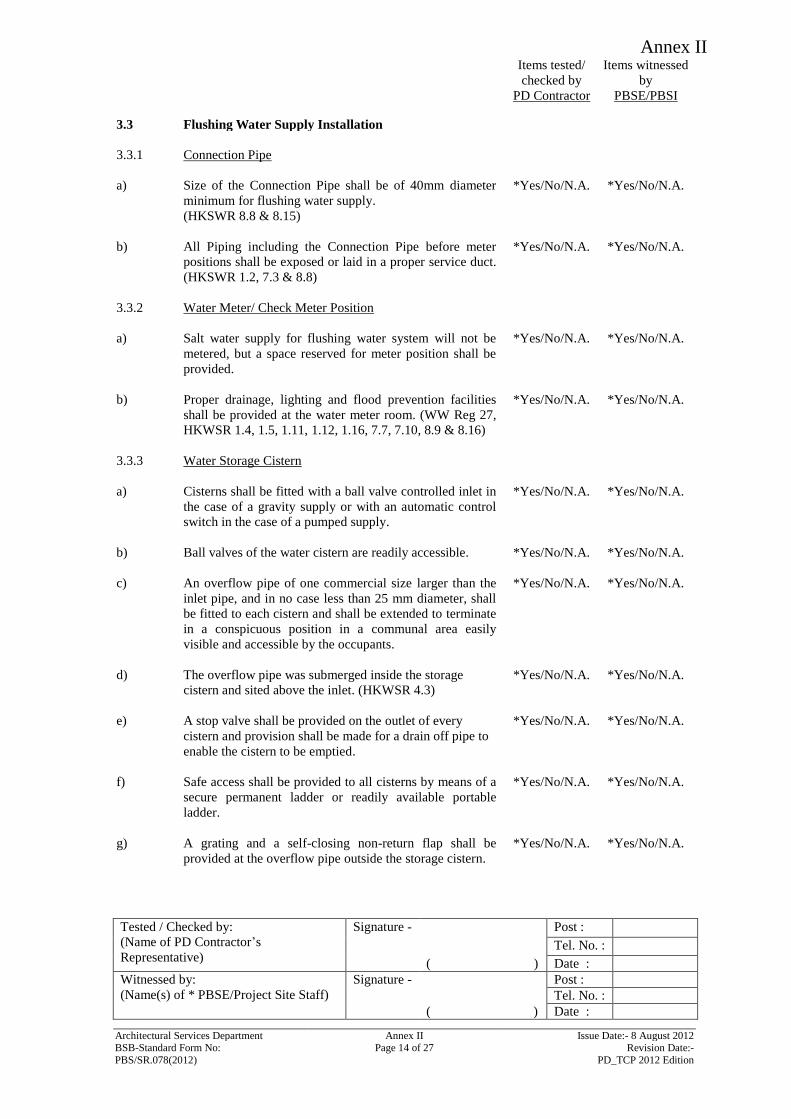
Annex II
Items tested/
checked by
PD Contractor
Items witnessed
by
PBSE/PBSI
Tested / Checked by:
(Name of PD Contractor’s
Representative)
Signature - Post :
Tel. No. :
( ) Date :
Witnessed by:
(Name(s) of * PBSE/Project Site Staff)
Signature - Post :
Tel. No. :
( ) Date :
Architectural Services Department Annex II Issue Date:- 8 August 2012 BSB-Standard Form No: Page 14 of 27 Revision Date:-
PBS/SR.078(2012) PD_TCP 2012 Edition
3.3 Flushing Water Supply Installation
3.3.1 Connection Pipe
a) Size of the Connection Pipe shall be of 40mm diameter
minimum for flushing water supply.
(HKSWR 8.8 & 8.15)
*Yes/No/N.A. *Yes/No/N.A.
b) All Piping including the Connection Pipe before meter
positions shall be exposed or laid in a proper service duct.
(HKSWR 1.2, 7.3 & 8.8)
*Yes/No/N.A. *Yes/No/N.A.
3.3.2 Water Meter/ Check Meter Position
a) Salt water supply for flushing water system will not be
metered, but a space reserved for meter position shall be
provided.
*Yes/No/N.A. *Yes/No/N.A.
b) Proper drainage, lighting and flood prevention facilities
shall be provided at the water meter room. (WW Reg 27,
HKWSR 1.4, 1.5, 1.11, 1.12, 1.16, 7.7, 7.10, 8.9 & 8.16)
*Yes/No/N.A. *Yes/No/N.A.
3.3.3 Water Storage Cistern
a) Cisterns shall be fitted with a ball valve controlled inlet in
the case of a gravity supply or with an automatic control
switch in the case of a pumped supply.
*Yes/No/N.A. *Yes/No/N.A.
b) Ball valves of the water cistern are readily accessible. *Yes/No/N.A. *Yes/No/N.A.
c) An overflow pipe of one commercial size larger than the
inlet pipe, and in no case less than 25 mm diameter, shall
be fitted to each cistern and shall be extended to terminate
in a conspicuous position in a communal area easily
visible and accessible by the occupants.
*Yes/No/N.A. *Yes/No/N.A.
d) The overflow pipe was submerged inside the storage
cistern and sited above the inlet. (HKWSR 4.3)
*Yes/No/N.A. *Yes/No/N.A.
e) A stop valve shall be provided on the outlet of every
cistern and provision shall be made for a drain off pipe to
enable the cistern to be emptied.
*Yes/No/N.A. *Yes/No/N.A.
f) Safe access shall be provided to all cisterns by means of a
secure permanent ladder or readily available portable
ladder.
*Yes/No/N.A. *Yes/No/N.A.
g) A grating and a self-closing non-return flap shall be
provided at the overflow pipe outside the storage cistern.
*Yes/No/N.A. *Yes/No/N.A.
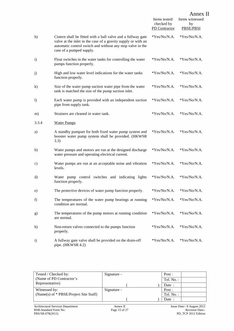
Annex II
Items tested/
checked by
PD Contractor
Items witnessed
by
PBSE/PBSI
Tested / Checked by:
(Name of PD Contractor’s
Representative)
Signature - Post :
Tel. No. :
( ) Date :
Witnessed by:
(Name(s) of * PBSE/Project Site Staff)
Signature - Post :
Tel. No. :
( ) Date :
Architectural Services Department Annex II Issue Date:- 8 August 2012 BSB-Standard Form No: Page 15 of 27 Revision Date:-
PBS/SR.078(2012) PD_TCP 2012 Edition
h) Cistern shall be fitted with a ball valve and a fullway gate
valve at the inlet in the case of a gravity supply or with an
automatic control switch and without any stop valve in the
case of a pumped supply.
*Yes/No/N.A. *Yes/No/N.A.
i) Float switches in the water tanks for controlling the water
pumps function properly.
*Yes/No/N.A. *Yes/No/N.A.
j) High and low water level indications for the water tanks
function properly.
*Yes/No/N.A. *Yes/No/N.A.
k) Size of the water pump suction water pipe from the water
tank is matched the size of the pump suction inlet.
*Yes/No/N.A. *Yes/No/N.A.
l) Each water pump is provided with an independent suction
pipe from supply tank.
*Yes/No/N.A. *Yes/No/N.A.
m) Strainers are cleaned in water tank. *Yes/No/N.A. *Yes/No/N.A.
3.3.4 Water Pumps
a) A standby pumpset for both fixed water pump system and
booster water pump system shall be provided. (HKWSR
3.3)
*Yes/No/N.A. *Yes/No/N.A.
b) Water pumps and motors are run at the designed discharge
water pressure and operating electrical current.
*Yes/No/N.A. *Yes/No/N.A.
c) Water pumps are run at an acceptable noise and vibration
levels.
*Yes/No/N.A. *Yes/No/N.A.
d) Water pump control switches and indicating lights
function properly.
*Yes/No/N.A. *Yes/No/N.A.
e) The protective devices of water pump function properly. *Yes/No/N.A. *Yes/No/N.A.
f) The temperatures of the water pump bearings at running
condition are normal.
*Yes/No/N.A. *Yes/No/N.A.
g) The temperatures of the pump motors at running condition
are normal.
*Yes/No/N.A. *Yes/No/N.A.
h) Non-return valves connected to the pumps function
properly.
*Yes/No/N.A. *Yes/No/N.A.
i) A fullway gate valve shall be provided on the drain-off
pipe. (HKWSR 4.2)
*Yes/No/N.A. *Yes/No/N.A.
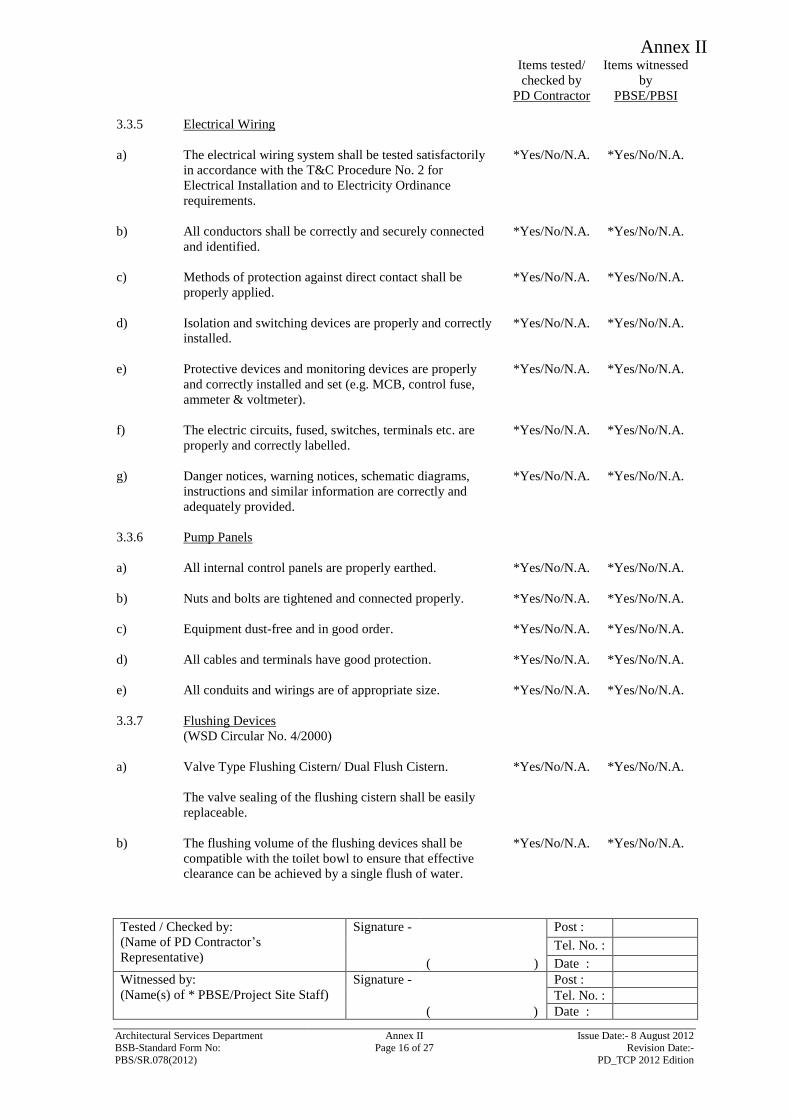
Annex II
Items tested/
checked by
PD Contractor
Items witnessed
by
PBSE/PBSI
Tested / Checked by:
(Name of PD Contractor’s
Representative)
Signature - Post :
Tel. No. :
( ) Date :
Witnessed by:
(Name(s) of * PBSE/Project Site Staff)
Signature - Post :
Tel. No. :
( ) Date :
Architectural Services Department Annex II Issue Date:- 8 August 2012 BSB-Standard Form No: Page 16 of 27 Revision Date:-
PBS/SR.078(2012) PD_TCP 2012 Edition
3.3.5 Electrical Wiring
a) The electrical wiring system shall be tested satisfactorily
in accordance with the T&C Procedure No. 2 for
Electrical Installation and to Electricity Ordinance
requirements.
*Yes/No/N.A. *Yes/No/N.A.
b) All conductors shall be correctly and securely connected
and identified.
*Yes/No/N.A. *Yes/No/N.A.
c) Methods of protection against direct contact shall be
properly applied.
*Yes/No/N.A. *Yes/No/N.A.
d) Isolation and switching devices are properly and correctly
installed.
*Yes/No/N.A. *Yes/No/N.A.
e) Protective devices and monitoring devices are properly
and correctly installed and set (e.g. MCB, control fuse,
ammeter & voltmeter).
*Yes/No/N.A. *Yes/No/N.A.
f) The electric circuits, fused, switches, terminals etc. are
properly and correctly labelled.
*Yes/No/N.A. *Yes/No/N.A.
g) Danger notices, warning notices, schematic diagrams,
instructions and similar information are correctly and
adequately provided.
*Yes/No/N.A. *Yes/No/N.A.
3.3.6 Pump Panels
a) All internal control panels are properly earthed. *Yes/No/N.A. *Yes/No/N.A.
b) Nuts and bolts are tightened and connected properly. *Yes/No/N.A. *Yes/No/N.A.
c) Equipment dust-free and in good order. *Yes/No/N.A. *Yes/No/N.A.
d) All cables and terminals have good protection. *Yes/No/N.A. *Yes/No/N.A.
e) All conduits and wirings are of appropriate size. *Yes/No/N.A. *Yes/No/N.A.
3.3.7 Flushing Devices
(WSD Circular No. 4/2000)
a) Valve Type Flushing Cistern/ Dual Flush Cistern. *Yes/No/N.A. *Yes/No/N.A.
The valve sealing of the flushing cistern shall be easily
replaceable.
b) The flushing volume of the flushing devices shall be
compatible with the toilet bowl to ensure that effective
clearance can be achieved by a single flush of water.
*Yes/No/N.A. *Yes/No/N.A.
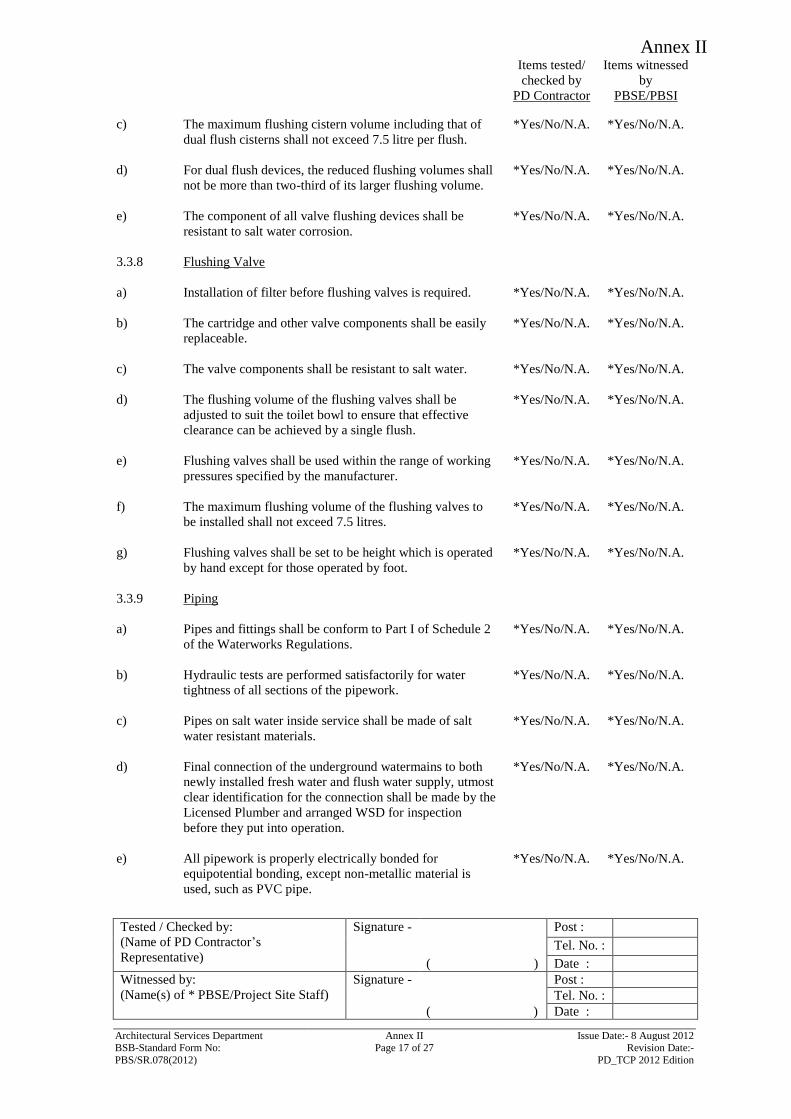
Annex II
Items tested/
checked by
PD Contractor
Items witnessed
by
PBSE/PBSI
Tested / Checked by:
(Name of PD Contractor’s
Representative)
Signature - Post :
Tel. No. :
( ) Date :
Witnessed by:
(Name(s) of * PBSE/Project Site Staff)
Signature - Post :
Tel. No. :
( ) Date :
Architectural Services Department Annex II Issue Date:- 8 August 2012 BSB-Standard Form No: Page 17 of 27 Revision Date:-
PBS/SR.078(2012) PD_TCP 2012 Edition
c) The maximum flushing cistern volume including that of
dual flush cisterns shall not exceed 7.5 litre per flush.
*Yes/No/N.A. *Yes/No/N.A.
d) For dual flush devices, the reduced flushing volumes shall
not be more than two-third of its larger flushing volume.
*Yes/No/N.A. *Yes/No/N.A.
e) The component of all valve flushing devices shall be
resistant to salt water corrosion.
*Yes/No/N.A. *Yes/No/N.A.
3.3.8 Flushing Valve
a) Installation of filter before flushing valves is required. *Yes/No/N.A. *Yes/No/N.A.
b) The cartridge and other valve components shall be easily
replaceable.
*Yes/No/N.A. *Yes/No/N.A.
c) The valve components shall be resistant to salt water. *Yes/No/N.A. *Yes/No/N.A.
d) The flushing volume of the flushing valves shall be
adjusted to suit the toilet bowl to ensure that effective
clearance can be achieved by a single flush.
*Yes/No/N.A. *Yes/No/N.A.
e) Flushing valves shall be used within the range of working
pressures specified by the manufacturer.
*Yes/No/N.A. *Yes/No/N.A.
f) The maximum flushing volume of the flushing valves to
be installed shall not exceed 7.5 litres.
*Yes/No/N.A. *Yes/No/N.A.
g) Flushing valves shall be set to be height which is operated
by hand except for those operated by foot.
*Yes/No/N.A. *Yes/No/N.A.
3.3.9 Piping
a) Pipes and fittings shall be conform to Part I of Schedule 2
of the Waterworks Regulations.
*Yes/No/N.A. *Yes/No/N.A.
b) Hydraulic tests are performed satisfactorily for water
tightness of all sections of the pipework.
*Yes/No/N.A. *Yes/No/N.A.
c) Pipes on salt water inside service shall be made of salt
water resistant materials.
*Yes/No/N.A. *Yes/No/N.A.
d) Final connection of the underground watermains to both
newly installed fresh water and flush water supply, utmost
clear identification for the connection shall be made by the
Licensed Plumber and arranged WSD for inspection
before they put into operation.
*Yes/No/N.A. *Yes/No/N.A.
e) All pipework is properly electrically bonded for
equipotential bonding, except non-metallic material is
used, such as PVC pipe.
*Yes/No/N.A. *Yes/No/N.A.
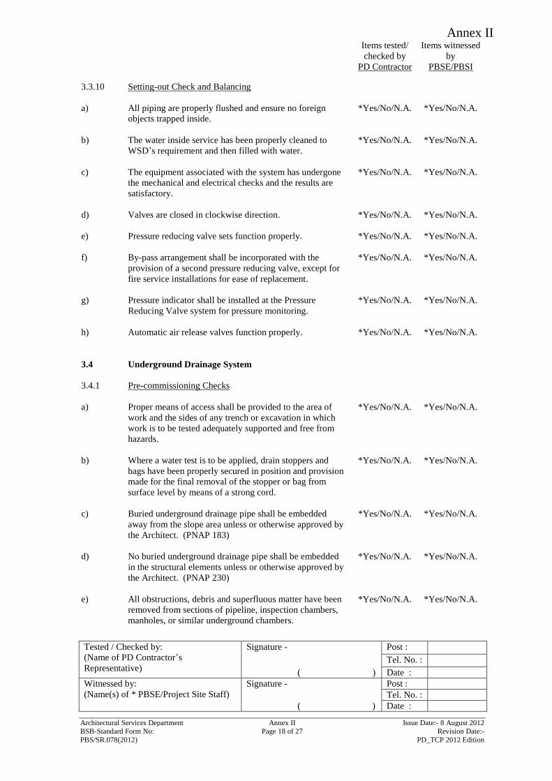
Annex II
Items tested/
checked by
PD Contractor
Items witnessed
by
PBSE/PBSI
Tested / Checked by:
(Name of PD Contractor’s
Representative)
Signature - Post :
Tel. No. :
( ) Date :
Witnessed by:
(Name(s) of * PBSE/Project Site Staff)
Signature - Post :
Tel. No. :
( ) Date :
Architectural Services Department Annex II Issue Date:- 8 August 2012 BSB-Standard Form No: Page 18 of 27 Revision Date:-
PBS/SR.078(2012) PD_TCP 2012 Edition
3.3.10 Setting-out Check and Balancing
a) All piping are properly flushed and ensure no foreign
objects trapped inside.
*Yes/No/N.A. *Yes/No/N.A.
b) The water inside service has been properly cleaned to
WSD’s requirement and then filled with water.
*Yes/No/N.A. *Yes/No/N.A.
c) The equipment associated with the system has undergone
the mechanical and electrical checks and the results are
satisfactory.
*Yes/No/N.A. *Yes/No/N.A.
d) Valves are closed in clockwise direction. *Yes/No/N.A. *Yes/No/N.A.
e) Pressure reducing valve sets function properly. *Yes/No/N.A. *Yes/No/N.A.
f) By-pass arrangement shall be incorporated with the
provision of a second pressure reducing valve, except for
fire service installations for ease of replacement.
*Yes/No/N.A. *Yes/No/N.A.
g) Pressure indicator shall be installed at the Pressure
Reducing Valve system for pressure monitoring.
*Yes/No/N.A. *Yes/No/N.A.
h) Automatic air release valves function properly. *Yes/No/N.A. *Yes/No/N.A.
3.4
Underground Drainage System
3.4.1
Pre-commissioning Checks
a)
Proper means of access shall be provided to the area of
work and the sides of any trench or excavation in which
work is to be tested adequately supported and free from
hazards.
*Yes/No/N.A. *Yes/No/N.A.
b) Where a water test is to be applied, drain stoppers and
bags have been properly secured in position and provision
made for the final removal of the stopper or bag from
surface level by means of a strong cord.
*Yes/No/N.A. *Yes/No/N.A.
c) Buried underground drainage pipe shall be embedded
away from the slope area unless or otherwise approved by
the Architect. (PNAP 183)
*Yes/No/N.A. *Yes/No/N.A.
d) No buried underground drainage pipe shall be embedded
in the structural elements unless or otherwise approved by
the Architect. (PNAP 230)
*Yes/No/N.A. *Yes/No/N.A.
e) All obstructions, debris and superfluous matter have been
removed from sections of pipeline, inspection chambers,
manholes, or similar underground chambers.
*Yes/No/N.A. *Yes/No/N.A.
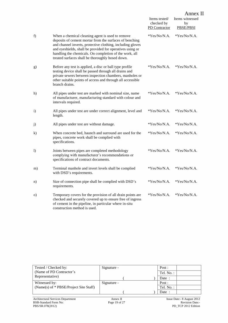
Annex II
Items tested/
checked by
PD Contractor
Items witnessed
by
PBSE/PBSI
Tested / Checked by:
(Name of PD Contractor’s
Representative)
Signature - Post :
Tel. No. :
( ) Date :
Witnessed by:
(Name(s) of * PBSE/Project Site Staff)
Signature - Post :
Tel. No. :
( ) Date :
Architectural Services Department Annex II Issue Date:- 8 August 2012 BSB-Standard Form No: Page 19 of 27 Revision Date:-
PBS/SR.078(2012) PD_TCP 2012 Edition
f) When a chemical cleaning agent is used to remove
deposits of cement mortar from the surfaces of benching
and channel inverts, protective clothing, including gloves
and eyeshields, shall be provided for operatives using or
handling the chemicals. On completion of the work, all
treated surfaces shall be thoroughly hosed down.
*Yes/No/N.A. *Yes/No/N.A.
g) Before any test is applied, a disc or ball type profile
testing device shall be passed through all drains and
private sewers between inspection chambers, manholes or
other suitable points of access and through all accessible
branch drains.
*Yes/No/N.A. *Yes/No/N.A.
h) All pipes under test are marked with nominal size, name
of manufacturer, manufacturing standard with colour and
intervals required.
*Yes/No/N.A. *Yes/No/N.A.
i) All pipes under test are under correct alignment, level and
length.
*Yes/No/N.A. *Yes/No/N.A.
j) All pipes under test are without damage. *Yes/No/N.A. *Yes/No/N.A.
k) When concrete bed, haunch and surround are used for the
pipes, concrete work shall be complied with
specifications.
*Yes/No/N.A. *Yes/No/N.A.
l) Joints between pipes are completed methodology
complying with manufacturer’s recommendations or
specifications of contract documents.
*Yes/No/N.A. *Yes/No/N.A.
m) Terminal manhole and invert levels shall be complied
with DSD’s requirements.
*Yes/No/N.A. *Yes/No/N.A.
n) Size of connection pipe shall be complied with DSD’s
requirements.
*Yes/No/N.A. *Yes/No/N.A.
o) Temporary covers for the provision of all drain points are
checked and securely covered up to ensure free of ingress
of cement in the pipeline, in particular where in-situ
construction method is used.
*Yes/No/N.A. *Yes/No/N.A.
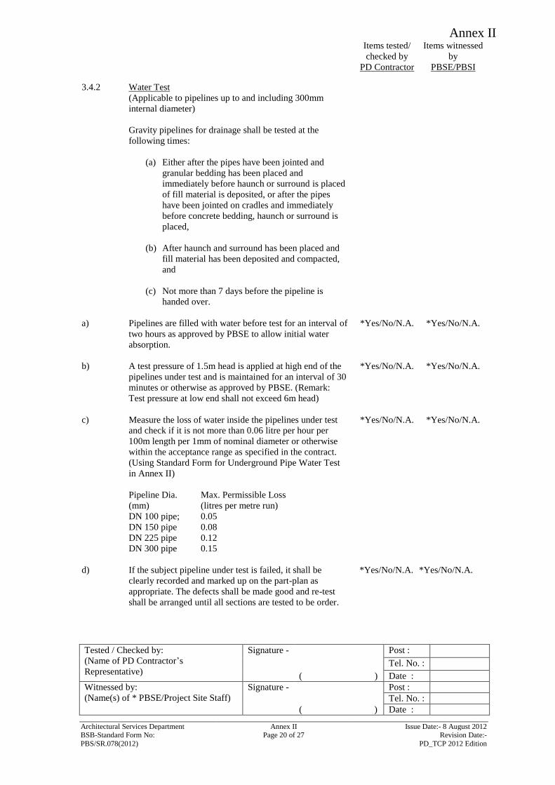
Annex II
Items tested/
checked by
PD Contractor
Items witnessed
by
PBSE/PBSI
Tested / Checked by:
(Name of PD Contractor’s
Representative)
Signature - Post :
Tel. No. :
( ) Date :
Witnessed by:
(Name(s) of * PBSE/Project Site Staff)
Signature - Post :
Tel. No. :
( ) Date :
Architectural Services Department Annex II Issue Date:- 8 August 2012 BSB-Standard Form No: Page 20 of 27 Revision Date:-
PBS/SR.078(2012) PD_TCP 2012 Edition
3.4.2 Water Test
(Applicable to pipelines up to and including 300mm
internal diameter)
Gravity pipelines for drainage shall be tested at the
following times:
(a) Either after the pipes have been jointed and
granular bedding has been placed and
immediately before haunch or surround is placed
of fill material is deposited, or after the pipes
have been jointed on cradles and immediately
before concrete bedding, haunch or surround is
placed,
(b) After haunch and surround has been placed and
fill material has been deposited and compacted,
and
(c) Not more than 7 days before the pipeline is
handed over.
a) Pipelines are filled with water before test for an interval of
two hours as approved by PBSE to allow initial water
absorption.
*Yes/No/N.A. *Yes/No/N.A.
b) A test pressure of 1.5m head is applied at high end of the
pipelines under test and is maintained for an interval of 30
minutes or otherwise as approved by PBSE. (Remark:
Test pressure at low end shall not exceed 6m head)
*Yes/No/N.A. *Yes/No/N.A.
c) Measure the loss of water inside the pipelines under test
and check if it is not more than 0.06 litre per hour per
100m length per 1mm of nominal diameter or otherwise
within the acceptance range as specified in the contract.
(Using Standard Form for Underground Pipe Water Test
in Annex II)
*Yes/No/N.A. *Yes/No/N.A.
Pipeline Dia.
(mm)
Max. Permissible Loss
(litres per metre run)
DN 100 pipe; 0.05
DN 150 pipe 0.08
DN 225 pipe 0.12
DN 300 pipe 0.15
d) If the subject pipeline under test is failed, it shall be
clearly recorded and marked up on the part-plan as
appropriate. The defects shall be made good and re-test
shall be arranged until all sections are tested to be order.
*Yes/No/N.A. *Yes/No/N.A.
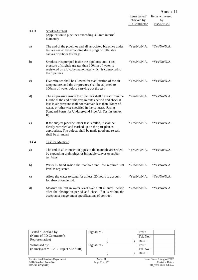
Annex II
Items tested/
checked by
PD Contractor
Items witnessed
by
PBSE/PBSI
Tested / Checked by:
(Name of PD Contractor’s
Representative)
Signature - Post :
Tel. No. :
( ) Date :
Witnessed by:
(Name(s) of * PBSE/Project Site Staff)
Signature - Post :
Tel. No. :
( ) Date :
Architectural Services Department Annex II Issue Date:- 8 August 2012 BSB-Standard Form No: Page 21 of 27 Revision Date:-
PBS/SR.078(2012) PD_TCP 2012 Edition
3.4.3 Smoke/Air Test
(Application to pipelines exceeding 300mm internal
diameter)
a) The end of the pipelines and all associated branches under
test are sealed by expanding drain plugs or inflatable
canvas or rubber test bags.
*Yes/No/N.A. *Yes/No/N.A.
b) Smoke/air is pumped inside the pipelines until a test
pressure of slightly greater than 100mm of water is
registered on a U-tube manometer which is connected to
the pipelines.
*Yes/No/N.A. *Yes/No/N.A.
c) Five minutes shall be allowed for stabilization of the air
temperature, and the air pressure shall be adjusted to
100mm of water before carrying out the test.
*Yes/No/N.A. *Yes/No/N.A.
d) The air pressure inside the pipelines shall be read from the
U-tube at the end of the five minutes period and check if
loss in air pressure shall not maintain less than 75mm of
water, or otherwise specified in the contract. (Using
Standard Form for Underground Pipe Air Test in Annex
II)
*Yes/No/N.A. *Yes/No/N.A.
e) If the subject pipeline under test is failed, it shall be
clearly recorded and marked up on the part-plan as
appropriate. The defects shall be made good and re-test
shall be arranged.
*Yes/No/N.A. *Yes/No/N.A.
3.4.4 Test for Manhole
a) The end of all connection pipes of the manhole are sealed
by expanding drain plugs or inflatable canvas or rubber
test bags.
*Yes/No/N.A. *Yes/No/N.A.
b) Water is filled inside the manhole until the required test
level is registered.
*Yes/No/N.A. *Yes/No/N.A.
c) Allow the water to stand for at least 20 hours to account
for absorption period.
*Yes/No/N.A. *Yes/No/N.A.
d) Measure the fall in water level over a 30 minutes’ period
after the absorption period and check if it is within the
acceptance range under specifications of contract.
*Yes/No/N.A. *Yes/No/N.A.
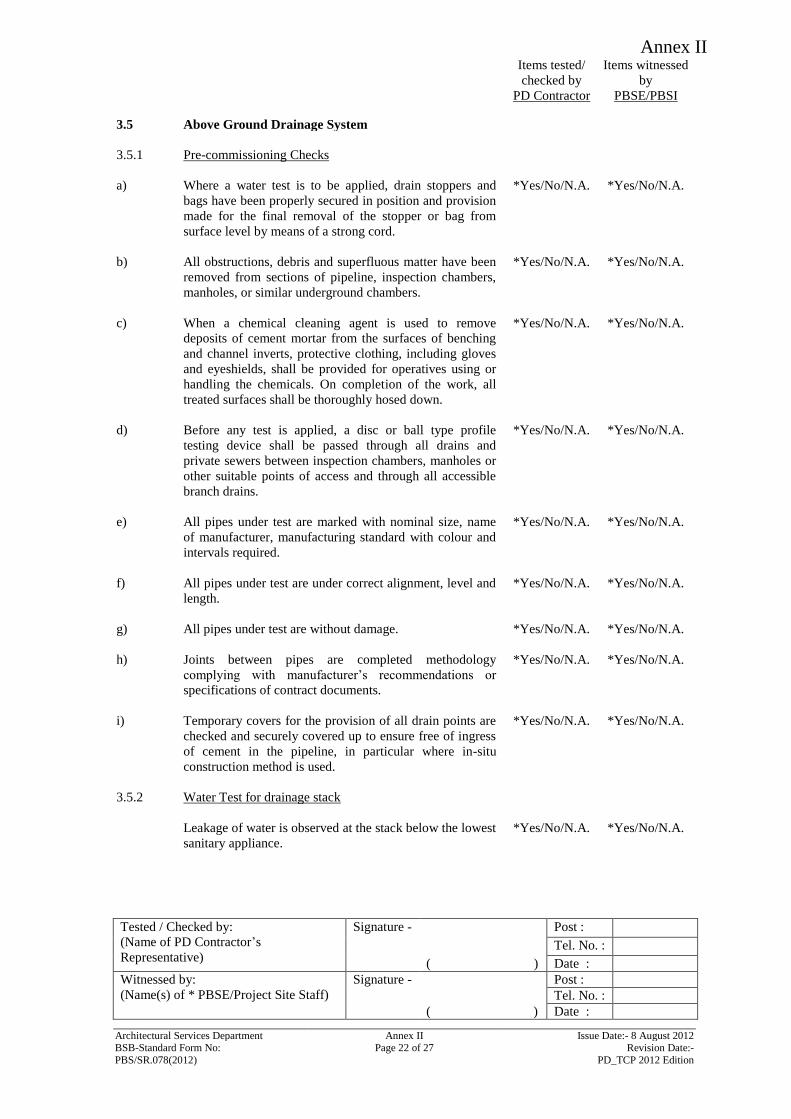
Annex II
Items tested/
checked by
PD Contractor
Items witnessed
by
PBSE/PBSI
Tested / Checked by:
(Name of PD Contractor’s
Representative)
Signature - Post :
Tel. No. :
( ) Date :
Witnessed by:
(Name(s) of * PBSE/Project Site Staff)
Signature - Post :
Tel. No. :
( ) Date :
Architectural Services Department Annex II Issue Date:- 8 August 2012 BSB-Standard Form No: Page 22 of 27 Revision Date:-
PBS/SR.078(2012) PD_TCP 2012 Edition
3.5 Above Ground Drainage System
3.5.1 Pre-commissioning Checks
a) Where a water test is to be applied, drain stoppers and
bags have been properly secured in position and provision
made for the final removal of the stopper or bag from
surface level by means of a strong cord.
*Yes/No/N.A. *Yes/No/N.A.
b) All obstructions, debris and superfluous matter have been
removed from sections of pipeline, inspection chambers,
manholes, or similar underground chambers.
*Yes/No/N.A. *Yes/No/N.A.
c) When a chemical cleaning agent is used to remove
deposits of cement mortar from the surfaces of benching
and channel inverts, protective clothing, including gloves
and eyeshields, shall be provided for operatives using or
handling the chemicals. On completion of the work, all
treated surfaces shall be thoroughly hosed down.
*Yes/No/N.A. *Yes/No/N.A.
d) Before any test is applied, a disc or ball type profile
testing device shall be passed through all drains and
private sewers between inspection chambers, manholes or
other suitable points of access and through all accessible
branch drains.
*Yes/No/N.A. *Yes/No/N.A.
e) All pipes under test are marked with nominal size, name
of manufacturer, manufacturing standard with colour and
intervals required.
*Yes/No/N.A. *Yes/No/N.A.
f) All pipes under test are under correct alignment, level and
length.
*Yes/No/N.A. *Yes/No/N.A.
g) All pipes under test are without damage. *Yes/No/N.A. *Yes/No/N.A.
h) Joints between pipes are completed methodology
complying with manufacturer’s recommendations or
specifications of contract documents.
*Yes/No/N.A. *Yes/No/N.A.
i) Temporary covers for the provision of all drain points are
checked and securely covered up to ensure free of ingress
of cement in the pipeline, in particular where in-situ
construction method is used.
*Yes/No/N.A. *Yes/No/N.A.
3.5.2 Water Test for drainage stack
Leakage of water is observed at the stack below the lowest
sanitary appliance.
*Yes/No/N.A. *Yes/No/N.A.
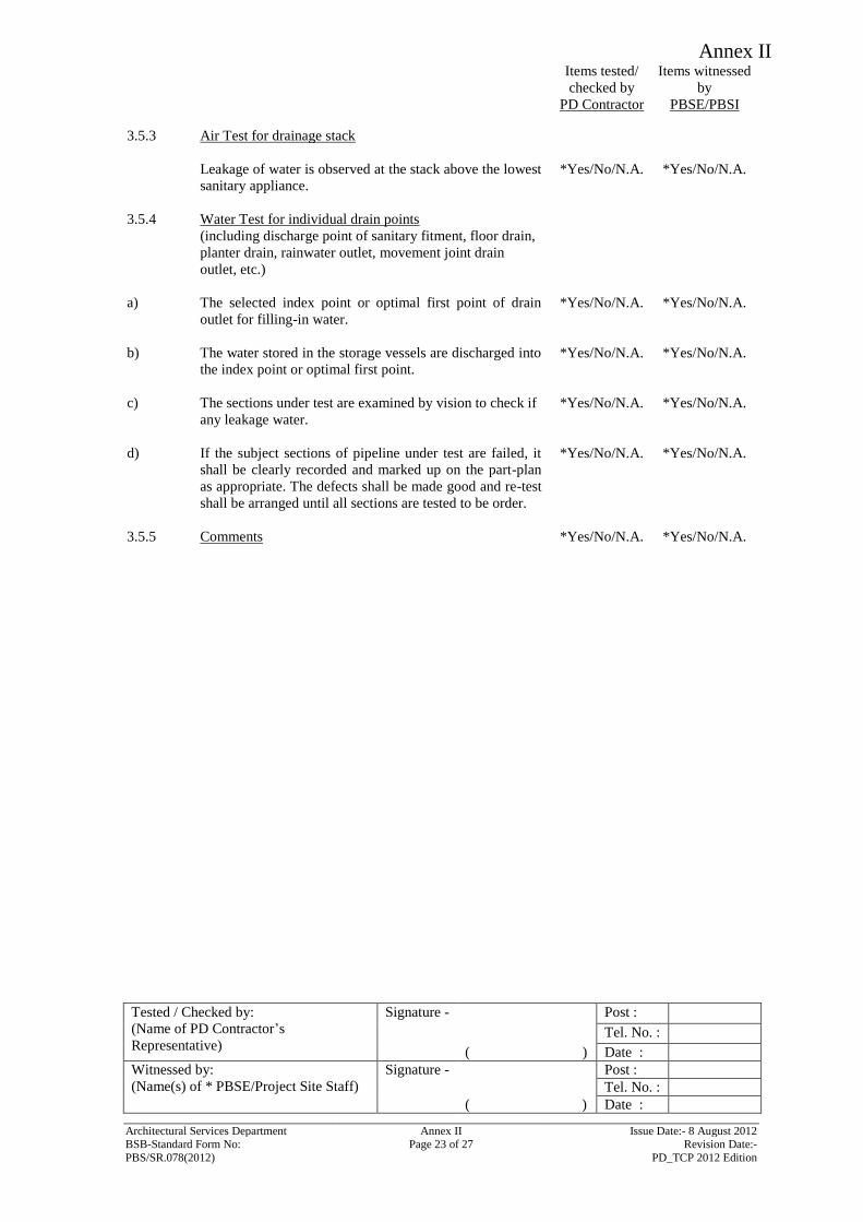
Annex II
Items tested/
checked by
PD Contractor
Items witnessed
by
PBSE/PBSI
Tested / Checked by:
(Name of PD Contractor’s
Representative)
Signature - Post :
Tel. No. :
( ) Date :
Witnessed by:
(Name(s) of * PBSE/Project Site Staff)
Signature - Post :
Tel. No. :
( ) Date :
Architectural Services Department Annex II Issue Date:- 8 August 2012 BSB-Standard Form No: Page 23 of 27 Revision Date:-
PBS/SR.078(2012) PD_TCP 2012 Edition
3.5.3 Air Test for drainage stack
Leakage of water is observed at the stack above the lowest
sanitary appliance.
*Yes/No/N.A. *Yes/No/N.A.
3.5.4 Water Test for individual drain points
(including discharge point of sanitary fitment, floor drain,
planter drain, rainwater outlet, movement joint drain
outlet, etc.)
a) The selected index point or optimal first point of drain
outlet for filling-in water.
*Yes/No/N.A. *Yes/No/N.A.
b) The water stored in the storage vessels are discharged into
the index point or optimal first point.
*Yes/No/N.A. *Yes/No/N.A.
c) The sections under test are examined by vision to check if
any leakage water.
*Yes/No/N.A. *Yes/No/N.A.
d) If the subject sections of pipeline under test are failed, it
shall be clearly recorded and marked up on the part-plan
as appropriate. The defects shall be made good and re-test
shall be arranged until all sections are tested to be order.
*Yes/No/N.A. *Yes/No/N.A.
3.5.5 Comments *Yes/No/N.A. *Yes/No/N.A.
Annex II
Annex II Issue Date:- 8 August 2012 Page 24 of 27 Revision Date:-
PD_TCP 2012 Edition
Part 4: Test Record attached to the Test Certificate
4.1 Test data
Proforma for recording following data can be found in the succeeding pages and
these shall be properly filled in before submission to the PBSE with any relevant
comments related to site conditions.
- Underground Pipe Water Test in Drainage Installation
- Underground Pipe Air Test in Drainage Installation
- Vibration Test – Equipment Vibration Measurement Record
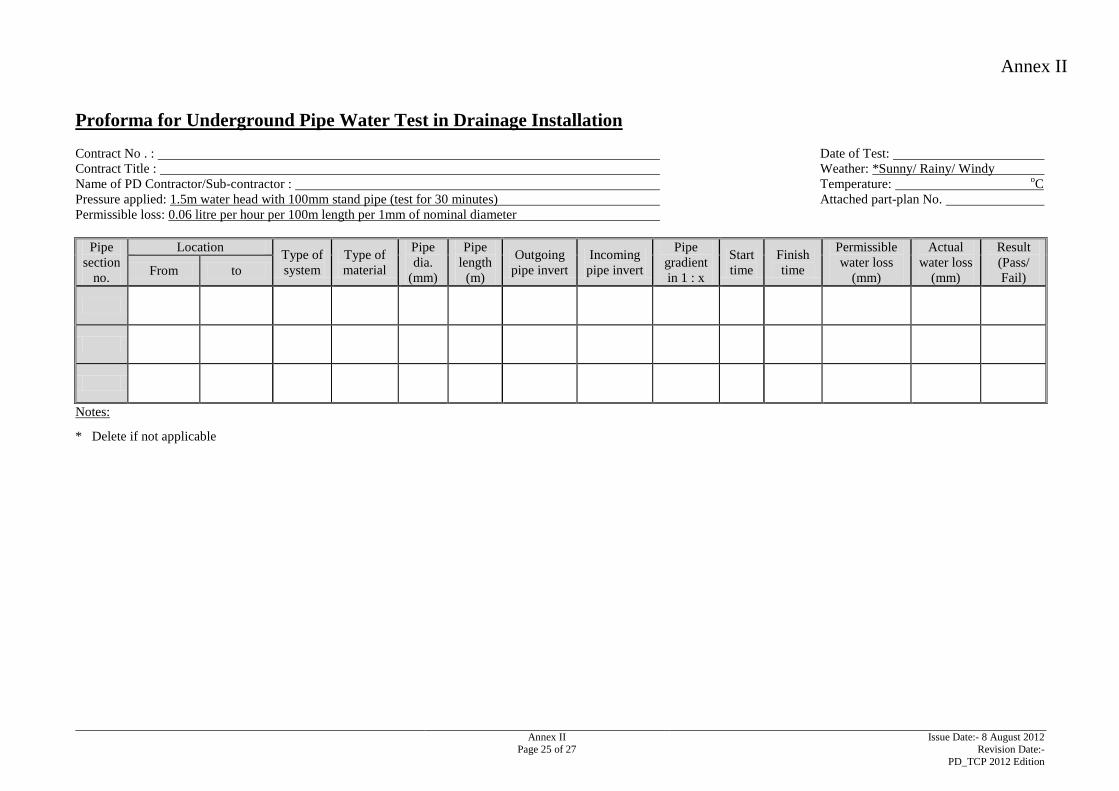
Annex II
Annex II Issue Date:- 8 August 2012
Page 25 of 27 Revision Date:-
PD_TCP 2012 Edition
Proforma for Underground Pipe Water Test in Drainage Installation
Contract No . : Date of Test:
Contract Title : Weather: *Sunny/ Rainy/ Windy
Name of PD Contractor/Sub-contractor : Temperature: oC
Pressure applied: 1.5m water head with 100mm stand pipe (test for 30 minutes) Attached part-plan No.
Permissible loss: 0.06 litre per hour per 100m length per 1mm of nominal diameter
Pipe
section
no.
Location Type of
system
Type of
material
Pipe
dia.
(mm)
Pipe
length
(m)
Outgoing
pipe invert
Incoming
pipe invert
Pipe
gradient
in 1 : x
Start
time
Finish
time
Permissible
water loss
(mm)
Actual
water loss
(mm)
Result
(Pass/
Fail) From to
Notes:
* Delete if not applicable
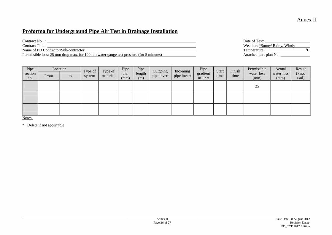
Annex II
Annex II Issue Date:- 8 August 2012
Page 26 of 27 Revision Date:-
PD_TCP 2012 Edition
Proforma for Underground Pipe Air Test in Drainage Installation
Contract No . : Date of Test:
Contract Title : Weather: *Sunny/ Rainy/ Windy
Name of PD Contractor/Sub-contractor : Temperature: oC
Permissible loss: 25 mm drop max. for 100mm water gauge test pressure (for 5 minutes) Attached part-plan No.
Pipe
section
no.
Location Type of
system
Type of
material
Pipe
dia.
(mm)
Pipe
length
(m)
Outgoing
pipe invert
Incoming
pipe invert
Pipe
gradient
in 1 : x
Start
time
Finish
time
Permissible
water loss
(mm)
Actual
water loss
(mm)
Result
(Pass/
Fail) From to
25
Notes:
* Delete if not applicable
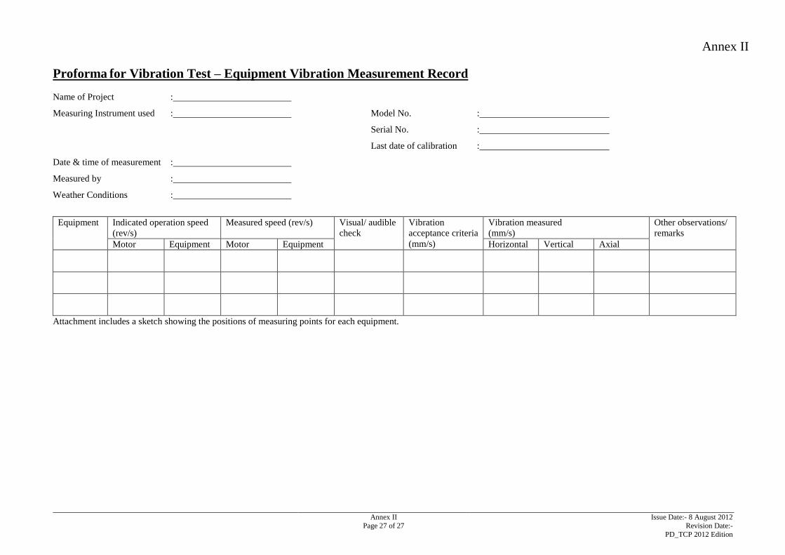
Annex II
Annex II Issue Date:- 8 August 2012
Page 27 of 27 Revision Date:-
PD_TCP 2012 Edition
Proforma for Vibration Test – Equipment Vibration Measurement Record
Name of Project :
Measuring Instrument used : Model No. :
Serial No. :
Last date of calibration :
Date & time of measurement :
Measured by :
Weather Conditions :
Equipment Indicated operation speed
(rev/s)
Measured speed (rev/s) Visual/ audible
check
Vibration
acceptance criteria
(mm/s)
Vibration measured
(mm/s)
Other observations/
remarks
Motor Equipment Motor Equipment Horizontal Vertical Axial
Attachment includes a sketch showing the positions of measuring points for each equipment.
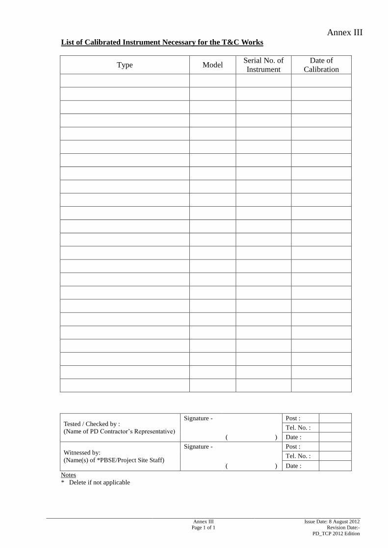
Annex III
Annex III Issue Date: 8 August 2012 Page 1 of 1 Revision Date:-
PD_TCP 2012 Edition
List of Calibrated Instrument Necessary for the T&C Works
Type Model Serial No. of
Instrument
Date of
Calibration
Tested / Checked by :
(Name of PD Contractor’s Representative)
Signature - Post :
Tel. No. :
( ) Date :
Witnessed by:
(Name(s) of *PBSE/Project Site Staff)
Signature - Post :
Tel. No. :
( ) Date :
Notes
* Delete if not applicable
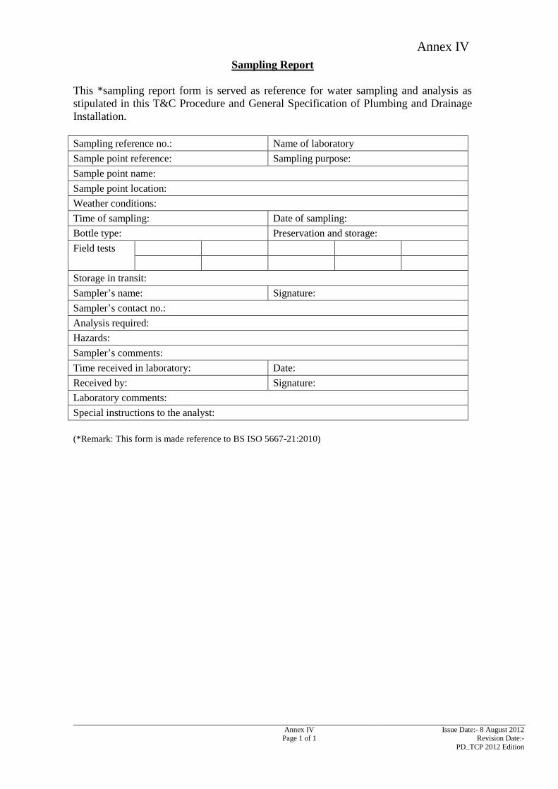
Annex IV
Annex IV Issue Date:- 8 August 2012 Page 1 of 1 Revision Date:-
PD_TCP 2012 Edition
Sampling Report
This *sampling report form is served as reference for water sampling and analysis as
stipulated in this T&C Procedure and General Specification of Plumbing and Drainage
Installation.
Sampling reference no.: Name of laboratory
Sample point reference: Sampling purpose:
Sample point name:
Sample point location:
Weather conditions:
Time of sampling: Date of sampling:
Bottle type: Preservation and storage:
Field tests
Storage in transit:
Sampler’s name: Signature:
Sampler’s contact no.:
Analysis required:
Hazards:
Sampler’s comments:
Time received in laboratory: Date:
Received by: Signature:
Laboratory comments:
Special instructions to the analyst:
(*Remark: This form is made reference to BS ISO 5667-21:2010)