chapter 5metrorailnagpur.com/dpr-pdf/chapter5.pdf · superstructure civil engineering . ... it is,...
TRANSCRIPT
CHAPTER 5
5.1 GENERAL 5.2 CIVIL STRUCTURES 5.3 CONSTRUCTION METHODOLOGY 5.4 PRE-CAST CONSTRUCTION 5.5 STRUCTURAL SYSTEM OF VIADUCT 5.6 CONSTRUCTION OF STATIONS 5.7 GEO-TECHNICAL INVESTIGATIONS 5.8 LAND 5.9 UTILITY DIVERSION TABLES
TABLE-5.1 STRATIGRAPHY OF ROCK TYPES IN NAGPUR REGION TABLE-5.2 DETAILS OF LABORATORY TESTS ON SOIL/WATER SAMPLES TABLE-5.3 DETAILS OF LABORATORY TESTS ON ROCK SAMPLES TABLE-5.4 SUMMARY OF BOREHOLE –N S CORRIDOR TABLE-5.5 SUMMARY OF BOREHOLE –E W CORRIDOR TABLE-5.6 RCC PILE DETAILS FOR NORTH – SOUTH CORRIDOR TABLE-5.7 OPEN FOUNDATION DETAILS FOR NORTH – SOUTH CORRIDOR TABLE-5.8 RCC PILE DETAILS FOR EAST WEST CORRIDOR TABLE-5.9 OPEN FOUNDATION DETAILS FOR EAST WEST CORRIDOR TABLE-5.10 DETAILS OF LAND REQUIRED FOR DEPOT TABLE-5.10A DETAILS OF LAND REQUIRED FOR RUNNING SECTION- EW CORRIDOR TABLE-5.10B DETAILS OF LAND REQUIRED FOR RUNNING SECTION- NS CORRIDOR TABLE-5.10C DETAILS OF LAND REQUIRED FOR STATIONS TABLE-5.10D DETAILS OF LAND REQUIRED FOR PARKING TABLE-5.10E ABSTRACT OF LAND REQUIREMENT TABLE-5.11 UTILITY RESPONSIBILITY DEPARTMENTS TABLE-5.12 LIST OF AFFECTED WATER SUPPLY LINES-NS CORRIDOR TABLE-5.13 LIST OF AFFECTED WATER SUPPLY LINES-EW CORRIDOR TABLE-5.14 LIST OF AFFECTED HT LINES-NS CORRIDOR TABLE-5.15 LIST OF AFFECTED HT POLES ON-NS CORRIDOR TABLE-5.16 LIST OF AFFECTED HT LINES-EW CORRIDOR TABLE-5.17 LIST OF AFFECTED HT POLES ON-EW CORRIDOR FIGURES FIG.5.1 GENERAL ARRANGEMENT OF STANDARD SPAN FIG.5.2 TYPICAL SECTION OF VIADUCT WITH U GIRDER FIG.5.3 TYPICAL SECTION OF VIADUCT WITH DOUBLE U GIRDER
FIG.5.4-5.7 LAUNCHING SCHEME OF PRE CAST SEGMENTAL CONSTRUCTION OF
SUPERSTRUCTURE
CIVIL ENGINEERING

FIG.5.9 DIMENSION OF TUNNEL SECTION FIG.5.10-5.11 TOP DOWN METHOD- CUT AND COVER CONSTRUCTION FIG.5.12 BORED TUNNEL AND UG STATION-CROSS PASSAGE WITH SUMP FIG.5.13 NORMAL SYSTEM FOR U GIRDER WITH CENTRE OHE FIG.5.14 THIRD RAIL SYSTEM FOR U GIRDER

Chapter 05: Civil Engineering
1/56 DETAILED PROJECT REPORT FOR NAGPUR METRO RAIL PROJECT NOV 2013
Chapter - 5 CIVIL ENGINEERING
5.1 GENERAL
This chapter deals with civil underground and elevated structure, Geotechnical investigation, construction methods, land requirements, Utility services and Traffic diversion during construction etc.
5.2 CIVIL STRUCTURES 5.2.1 Underground Section
Presently, there is no “Underground Section” and as such this para is not required. But, there may be some underground section at a later stage. Keeping in view of the same, this has been included. Tunnel excavation for underground section is generally carried out by Tunnel Boring Machines. Tunnel boring machines (TBMs) capable of drilling in soft and hard rocks can be successfully employed for boring tunnels through the rocky stratum.
5.2.2 Underground Stations The underground station has been proposed as cut and cover with top-down method. The diaphragm walls for such station constructions would be 80 to 100 cm. thick and will function as a permanent side wall of the station. It is, therefore, necessary to construct the diaphragm walls absolutely watertight and with the required concrete strength. By resorting to top-down method the surface could be restored quickly and further excavations and construction of the station will not hamper the surface activity.
5.2.3 Cut and Cover Method of Construction of Underground Station Cut and Cover mainly consists of following steps:
1. Diversion of utilities 2. Construction of support walls 3. Excavation between the support walls along with the installation of struts
between the two walls to keep them in position. 4. Construction of tunnel/structure and removal of temporary struts.
Chapter 05: Civil Engineering
2/56 DETAILED PROJECT REPORT FOR NAGPUR METRO RAIL PROJECT NOV 2013
5. Back filling and restoration of the surface
5.2.4 Utility Diversion: It is suggested that all utilities falling within excavation area are diverted away in advance to avoid damage to such utilities during the excavation/ construction phase. The cross utilities, however has to be kept supported. It is suggested that pressure water pipelines crossing the proposed cut area are provided with valves on both sides of the cut so that the cut area can be isolated in case of any leakage to the pipeline to avoid flooding of the cut/damage to the works.
5.2.5 Support Walls:
Most commonly used support wall is RCC Diaphragm Wall. The advantage of diaphragm wall is that the same can be used as part of permanent structure. The modern techniques are now available where water-stop can be inserted at the joints of two diaphragm wall panels to avoid seepage through the joints. It is also now possible to ensure the verticality of the diaphragm wall panels to avoid any infringement problem later on. Typically the diaphragm wall of 80 cm to 1 meter thickness is sufficient to do the cut and cover construction. The various advantages of diaphragm wall are as follows. (a) It is rigid type of support system and therefore ensures the maximum safety against
settlement to the adjacent structures.
(b) Can be used as part of the permanent structure and, therefore, considered economical.
(c) With diaphragm wall it is possible to construct an underground structure by top down method. In this method top slab is cast once the excavation is reached to the top slab level with rigid connections to the diaphragm wall which can be achieved by leaving couplers in the diaphragm wall reinforcement at appropriate level. This top slab then acts as strut between the two support walls and gives much more rigidity and safety to the construction. Excavation thereafter can be completed. This also helps in restoration of the surface faster without waiting for full structure to be completed.
The other support walls which can be used depending on the site conditions are as follows: (a) Sheet Piles : ‘Z’/ ‘U’ sheet piles cane be used as temporary support wall. This can be
advantageous where it is possible to re-use the sheet pile again and again and therefore, economy can be achieved However the main concern remains, driving of sheet piles causes vibrations/noise to the adjacent buildings. This may sometimes lead to damage to the building and most of the time causes inconvenience to the

Chapter 05: Civil Engineering
3/56 DETAILED PROJECT REPORT FOR NAGPUR METRO RAIL PROJECT NOV 2013
occupants of the building. Situation becomes more critical if sensitive buildings are adjacent to the alignment like hospitals, schools, laboratories, etc. Silent pile driving equipments however are now available and can be used where such problems are anticipated.
(b) Retaining Casing Piles: This is suitable for situation where the cut and cover is to be done in partly soil and partly rock. The top soil retaining structure can be done with the help of Casing pile which is then grouted with cement slurry. This is considered suitable in case of shallow level, non-uniform, uneven nature of rock head surface which render the construction of sheet piles/diaphragm wall impracticable. These are suitable up to 7-meter depth. The common diameter used for such casing pile is 2.00-2.50 m dia.
(c) Soldier Piles and Lagging: Steel piles (H Section or I section) are driven into the
ground at suitable interval (normally 1-1.5 m) centre-to-centre depending on the section and depth of excavation. The gap between two piles is covered with suitable lagging of timber planks/shot-creting /steel sheets/GI sheets during the process of excavation.
(d) Secant Piles: are cast-in-situ bored piles constructed contiguously to each other so that it forms a rigid continuous wall. This is considered an alternative to diaphragm wall where due to soil conditions it is not advisable to construct diaphragm wall from the consideration of settlement during the trenching operation. 800 to 1000 mm dia piles are commonly used. Two alternate soft piles are driven and cast in such a way that the new pile partly cuts into earlier constructed piles. This new pile is constructed with suitable reinforcement. With this, alternate soft and hard pile is constructed. This has got all the advantages of diaphragm wall. However, this wall cannot be used as part of permanent structure and permanent structure has to be constructed in- side of this temporary wall.
5.2.6 Anchors: As an alternative to the struts, soil/rock anchors can be used to keep these support walls in position. This gives additional advantage as clear space is available between two support walls and progress of excavation & construction is much faster as compared to the case where large number of struts is provided which create hindrance to the movement of equipments and material & thus affects the progress adversely. The combination of all the type of retaining walls, struts/anchors may be necessary for the project to suit the particular site. Based on the above broad principle, the support walls system for cut and cover shall be chosen for particular locations.
Chapter 05: Civil Engineering
4/56 DETAILED PROJECT REPORT FOR NAGPUR METRO RAIL PROJECT NOV 2013
5.2.7 Elevated Section - Choice of Superstructure The choice of superstructure has to be made keeping in view the ease of constructability and the maximum standardization of the formwork for a wide span ranges.
The segmental construction has been chosen mainly due to the following advantages:
• Segmental construction is an efficient and economical method for a large range of span lengths and types of structures. Structures with sharp curves and variable super elevation can be easily accommodated.
• Segmental construction permits a reduction of construction time as segments may
be manufactured while substructure work proceeds and assembled rapidly thereafter.
• Segmental construction protects the environment as only space required for
foundation and sub-station is required at site. The superstructure is manufactured at a place away from busy areas and placement of superstructure is done with the system erected from piers at heights.
• Segments are easy to stack in the casting yard/stacking yard in more than one
layer, thereby saving in requirement of space. • It is easier to transport smaller segments by road trailers on city roads. • It is easy to incorporate last minute changes in span configuration if the site
situation so warrants. • Interference to the traffic during construction is significantly reduced. • Segmental construction contributes towards aesthetically pleasing structures and
good finishes. • The overall labour requirement is less than that for conventional methods. • Better quality control is possible in the casting yard. • During construction, the technique shows an exceptionally high record of safety.
5.2.8 Types of Superstructures for Elevated Section
(A) Pre-cast segmental box girder using external unbounded tendon (B) Pre-cast segmental U-Channel Superstructure with internal pre-stressing. Comparative advantages/disadvantages of the above two types are given below:
A. Precast Segmental Box Girder using External Unbounded Tendon. This essentially consists of precast segmental construction with external pre-
stressing and dry joints and is by far most preferred technique in fast track projects. In such construction the pre-stressing is placed outside the structural concrete
Chapter 05: Civil Engineering
5/56 DETAILED PROJECT REPORT FOR NAGPUR METRO RAIL PROJECT NOV 2013
(inside the box section) and protected with high density polyethylene tubes, which are grouted with special wax or cement. The match cast joints at the interface of two segments are provided with shear keys as in traditional segmental construction. However, epoxy is dispensed with because water tight seal at the segment joints is not required because tendons are laid externally & protected by special wax or cement.
The main advantages of dry-jointed externally pre-stressed precast segmental
construction can be summarized as follows:-
• Simplification of all post-tensioning operations, especially installation of tendons.
• Reduction in structural concrete thickness as no space is occupied by the tendons inside the concrete.
• Good corrosion protection due to tendons in polyethylene ducts, the grout inspection is easier and leaks, if any, can be identified during the grouting process.
• Simplified segment casting. There is no concern about alignment of tendons. Increased speed of construction.
• The elimination of the epoxy from the match-cast joints reduces costs and increases speed of construction further.
• Replacement of tendons in case of distress is possible and can be done in a safe and convenient manner.
• Facility for inspection and monitoring of tendons during the entire service life of the structure.
Precast Segmental Box Girder using internal tendon is also use. B. Precast Segmental U-Channel Superstructure with Internal Pre-stressing. The single U type of viaduct structure is also a precast segmental construction with
internal pre-stressing and requires gluing and temporary pre-stressing of segments. The match cast joints at the interface of two segments are also provided with shear keys. The main advantages for this type of structural configuration of superstructure are:
1. Built in sound barrier. 2. Built in cable support and system function.

Chapter 05: Civil Engineering
6/56 DETAILED PROJECT REPORT FOR NAGPUR METRO RAIL PROJECT NOV 2013
3. Possibility to lower the longitudinal profile by approximately 1m compared to conventional design.
4. Built in structural elements capable to maintain the trains on the bridge in case
of derailment (a standard barrier design allow this) 5. Built in maintenance and evacuation path on either side of the track.
5.3 CONSTRUCTION METHODOLOGY
For the elevated sections it is recommended to have pre-cast segmental construction for super structure for the viaduct. For stations also the superstructure is generally of pre-cast members. The pre-cast construction will have following advantages:- • Reduction in construction period due to concurrent working for substructure and
superstructure. • For segmental, pre-cast element (of generally 3.0m length), transportation from
construction depot to site is easy and economical. • Minimum inconvenience is caused to the public utilizing the road as the
superstructure launching is carried out through launching girder requiring narrow width of the road.
• As the pre-cast elements are cast on production line in a construction depot, very good quality can be ensured.
• The method is environment friendly as no concreting work is carried at site for the superstructure.
5.4 PRE-CAST CONSTRUCTION
5.4.1 Casting of Segments For viaducts segmental pre-cast construction requires a casting yard. The construction
depot will have facilities for casting beds, curing and stacking area, batching plant with storage facilities for aggregates and cement, site testing laboratories, reinforcement steel yard and fabrication yard etc. An area of about 2.5 Ha. To 3.0 Ha. is required for each construction depot.
For casting of segments both long line and short line method can be adopted. However
the long line method is more suitable for spans curved in plan while short line method is good for straight spans. A high degree of accuracy is required for setting out the curves on long line method for which pre calculation of offsets is necessary. Match casting of segments is required in either method. The cast segments are cured on the bed as well as in stacking yard. Ends of the segments are to be made rough through sand blasting so that gluing of segments can be effective.

Chapter 05: Civil Engineering
7/56 DETAILED PROJECT REPORT FOR NAGPUR METRO RAIL PROJECT NOV 2013
The cast segment will be transported on trailers and launched in position through launching girders.
5.4.2 Launching Scheme
Launching girder is specially designed for launching of segments. The suggested
launching scheme is designed in such a way that initially the launching girder is erected on pier head at one end of the work. The segments are lifted in sequence and when the lifting is over, they are dry matched while hanging from the launching girder. After dry matching, the
Segments are glued with epoxy and pre-stressed from one end. The girder is lowered on the temporary / permanent bearings after pre-stressing. The launching girder then moves over the launched span to next span and the sequences continue.
5.5 STRUCTURAL SYSTEM OF VIADUCT
5.5.1 Superstructure
The superstructure of a large part of the viaduct comprises of simply supported spans. However at major crossing/over or along existing bridge, special steel or continuous unit will be provided.
Normally the U-Channel girder having a soffit width of 9.0 m (approx) accommodates the two tracks situated at 3.7m (Tangent & upto 150m curvature) to 4.0m (90m curvature) c/c. The U-Channel superstructure for almost all the simply supported standard spans will be constructed by pre-cast pre-stressed segmental construction with epoxy bonded joints.
The max spans c/c of piers of standard simply supported spans constructed by pre-cast segmental construction technique has been proposed as 28.0m. The usual segments shall be 3.0m in length except the Diaphragm segments, which shall be 2.0m each. The other standard spans (c/c of pier) comprises of 25.0m, 31.0m, 22.0m, 19.0m & 16.0m, which shall be made by removing/adding usual segments of 3.0m each from the center of the span. Depth of the superstructure is so chosen that top of flange of U-Channel will be used as a evacuation walkway in an emergency.
The dimensions of end diaphragm will be finalized based on simply supported span of 31.0m and the same will be also kept for all simply supported standard span. The top level of both the end diaphragms of adjoining spans on the same piers is kept same so that expansion joint can be installed at top and continuity of profile of end diaphragm on the same pier can be maintained. The arrangement has been selected from aesthetic considerations.
The economical span (i.e. with optimum pre-stressing ratio) will be designed for the 25m situation.
Chapter 05: Civil Engineering
8/56 DETAILED PROJECT REPORT FOR NAGPUR METRO RAIL PROJECT NOV 2013
Standard span up to 28.0m will be provided throughout the viaduct as far as possible. At crossings, where spans requires to be increased upto 31.0m, simply supported spans will be provided.
The location where the open foundations are possible, the spans of 16m will be provided.
For major crossing having spans greater than 31.0m, special units normally of 3 –span construction or steel girders have been envisaged.
All these continuous units ( in case provided at obligatory location) will be constructed by cast-in-situ balanced cantilever construction technique. The top profile of superstructure of continuous unit (for the full length) will be retained the same as for standard spans so that evacuation walkway will be available even in continuous units. The increase in depth of U-channel will be accomplished by thickening the soffit slab (towards downside). At the end of continuous unit, the profile and thickness of soffit slab will be done to the extent that it will match with the profile and depth of end diaphragm of adjoining simply supported spans. The thickness of soffit slab will be increased smoothly toward penultimate support. In order to reduce the dead weight of the girder, voids will be also provided in the thickened soffit slab at bottom. These will be circular near the end of continuous unit and oblong near the penultimate support.
5.5.2 Substructure
The viaduct superstructure will be supported on single cast-in-place RC pier. The shape
of the pier follows the flow of forces. For the standard spans, the pier gradually widens at the top to support the bearing under the box webs. At this preliminary design stage, the size of pier is found to be limited to 1.8m to 2.0 m diameter of circular shape for most of its height so that it occupies the minimum space at ground level where the alignment often follows the central verge of existing roads.
To prevent the direct collision of vehicle to pier, a Jersey Shaped crash barrier of 1.0 m
height above existing road level has been provided all around the pier. A gap of 25 mm has also been provided in between the crash barrier and outer face of pier. The shape of upper part of pier has been so dimensioned that a required clearance of 5.5 m is always available on road side beyond vertical plane drawn on outer face of crash barrier. In such a situation, the minimum height of rail above the existing road is 8.4 m.
The longitudinal center to center spacing of elastomeric/pot bearing over a pier would be
about 1.8 m. The space between the elastomeric bearings will be utilized for placing the lifting jack required for the replacement of elastomeric bearing. An outward slope of 1:200 will be provided at pier top for the drainage due to spilling of rainwater, if any.
The transverse spacing between bearings would be 3.2 m (to be studied in more details). The orientation and dimensions of the piers for the continuous units or steel girder
(simply supported span) have to be carefully selected to ensure minimum occupation at

Chapter 05: Civil Engineering
9/56 DETAILED PROJECT REPORT FOR NAGPUR METRO RAIL PROJECT NOV 2013
ground level traffic. Since the vertical and horizontal loads will vary from pier to pier, this will be catered to by selecting the appropriate structural dimensions.
5.5.3 Foundation Recommendation
Depending on the nature of soil, type of proposed structure and expected loads on foundations, the recommended type of foundation is generally pile foundation except for a few locations where hard strata was located close to ground level. Pile capacities have been calculated as per IS 2911 Part 2 and IRC 78 while allowable bearing capacity for shallow open footing has been computed from the equation as per IS: 6403 – 1981. PILE FOUNDATION Pile foundation is a fissible foundation scheme that may be designed where the loadings are heavy/medium, upper strata are loose/soft or filled up, and depth of water table is less. The pile load bearing capacity is calculated in as per IS 2911 Part 2 & IRC: 78-2000. OPEN FOUNDATION For the prevailing soil conditions and type of structures, it was observed that shallow open footings can be provided at certain locations. Allowable bearing capacity for shallow open footing has been computed from the equation as per IS: 6403 – 1981 & Settlement shall be determined for unit pressure for a specified width of footing based on Corrected SPT values between the level of base of footing and the depth equal to 1.5 to 2.0 times the width of footing. Corrections shall be applied as applicable. Refer; IS: 8009 (Part-1).
5.5.4 Deck – Simple Spans
5.5.4.1 Deck – Simple Spans ‘U’ Girder Salient features of the precast segmental construction method technique as envisaged
for the project under consideration are indicated below: Salient features of the pre-cast segmental construction method technique as envisaged
for the project under consideration are indicated below:
The superstructure shall be constructed “span by span” sequentially, starting at one end of a continuous stretch and finishing at the other end. Nos. of launching girders may be required so as to work on different stretches simultaneously to enable completion of the project in time.
The number of “breaks” in the stretch can be identified by nos of continuous units.
The suggested method of erection will be detailed in drawings to be prepared. The launching girder (or, more accurately, the “assembly truss”) is capable of supporting the

Chapter 05: Civil Engineering
10/56 DETAILED PROJECT REPORT FOR NAGPUR METRO RAIL PROJECT NOV 2013
entire dead load of one span and transferring it to the temporary brackets attached to the pier. The governing weight of the segments will be of the order of 55t (to be finalized). The launching girder envisaged will be slightly greater than two span lengths. It must be able to negotiate curves in conjunction with temporary brackets.
Transportation of segments from casting yard to the point of erection will be effected by appropriately designed low-bedded trailors (tyre-mounted). The segments can be lifted and erected using erection portal gantry moving on launching girder.
U-girder segments shall be match cast at the casting yard before being transported to location and erected in position. Post-tensioned cables shall be threaded in-situ and tensioned from one end. It is emphasized that for pre-cast segmental construction only one-end pre-stressing shall be used.
The pre-stressing steel and pre-stressing system steel accessories shall be subjected to an acceptance test prior to their actual use on the works. The tests for the system shall be as per FIP Recommendations as stipulated in the special specifications. Only multi-strand jacks shall be used for tensioning of cables. Direct and indirect force measurement device (e.g. Pressure Gauge) shall be attached in consultation with system manufacturer.
The Contractor shall be responsible for the proper handling, lifting, storing, transporting and erection of all segments so that they may be placed in the structure without damage. Segments shall be maintained in an upright position at all times and shall be stored, lifted and/or moved in a manner to prevent torsion and other undue stress. Members shall be lifted, hoisted or stored with lifting devices approved on the shop drawings
5.5.4.2 Deck – Simple Spans Box Girder The superstructure shall be constructed “span by span” sequentially, starting at one end of a continuous stretch and finishing at the other end. Nos. of launching girders may be required so as to work on different stretches simultaneously to enable completion of the project in time.
The number of “breaks” in the stretch can be identified by Nos. of continuous units &
stations. The suggested method of erection will be detailed in drawings to be prepared, at the time
of detailed design. The launching girder (or, more accurately, the “assembly truss”) is capable of supporting the entire dead load of one span and transferring it to the temporary brackets attached to the pier. The governing weight of the segments will be of the order of 50t (to be finalized). The launching girder envisaged will be slightly longer than two span lengths. It must be able to negotiate curves in conjunction with temporary brackets.

Chapter 05: Civil Engineering
11/56 DETAILED PROJECT REPORT FOR NAGPUR METRO RAIL PROJECT NOV 2013
Transportation of segments from casting yard to the point of erection will be effected by appropriately designed low-bedded trailers (tyre-mounted). The segments can be lifted and erected using erection portal gantry moving on launching girder.
Box girder segments shall be match cast at the casting yard before being transported to
location and erected in position. Post-tensioned cables shall be threaded in-situ and tensioned from one end. It is emphasized that for precast segmental construction only one-end pre-stressing shall be used.
The pre-stressing steel and pre-stressing system steel accessories shall be subjected to
an acceptance test prior to their actual use on the works. The tests for the system shall be as per FIP Recommendations as stipulated in the special specifications. Only multi-strand jacks shall be used for tensioning of cables. Direct and indirect force measurement device (e.g. Pressure Gauge) shall be attached in consultation with system manufacturer.
The Contractor shall be responsible for the proper handling, lifting, storing, transporting
and erection of all segments so that they may be placed in the structure without damage. Segments shall be maintained in an upright position at all times and shall be stored, lifted and/or moved in a manner to prevent torsion and other undue stress. Members shall be lifted, hoisted or stored with lifting devices approved on the shop drawings.
5.5.5 Epoxy Bonded Joints and Shear Keys A minimum compressive stress of 3 kg/sq cm shall be provided uniformly over the cross-
section for the closure stress on the epoxied joint until the epoxy has set. The curing period for application of the compressive stress, method of mixing and application of epoxy and all related aspects including surface preparation shall be as per approved manufacturer’s specifications.
The purpose of the epoxy joint, which is about 1mm on each mating surface, shall be to
serve as lubricant during segment positioning, to provide Waterproofing of the joints for durability in service conditions and to provide a seal to
avoid cross-over of grout during grouting of one cable into other ducts. The epoxy shall be special purpose and meet requirements of relevant provision of FIP
(International Federation of Pre-stressed Concrete)
The temporary compressive stress during the curing period shall be applied by approved external temporary bar pre-stressing (such as Macalloy or Diwidag bar systems or approved equivalent).

Chapter 05: Civil Engineering
12/56 DETAILED PROJECT REPORT FOR NAGPUR METRO RAIL PROJECT NOV 2013
5.6 CONSTRUCTION OF STATIONS
It is proposed to construct the elevated stations with elevated concourse over the road at most of the locations to minimize land acquisition. To keep the rail level low, it is proposed not to take viaduct through the stations. Thus a separate structural configuration is required (although this may necessitate the break in the launching operations at each station location) Sub-structure for the station portion will also be similar to that of viaduct and will be carried out in the same manner. However, there will be single viaduct column in the station area, which will be located on the median and supporting the concourse girders by a cantilever arm so as to eliminate the columns on right of way.
5.6.1 Grade of Concrete
It is proposed to carry out construction work with design mix concrete through computerized automatic Batching Plants with following grade of concrete for various members as per design requirement/durability considerations.
i) Piles - M -35
ii) Pile cap and open foundation - M -35 iii) Piers - M -40 iv) All precast element for viaduct and station - M -45 v) Cantilever piers and portals - M -45 - M -60 vi) Other miscellaneous structure - M -30
For all the main structures, permeability test on concrete sample is recommended to ensure impermeable concrete.
5.6.2 Reinforcement and pre-stressed Steel
It is proposed to use HYSD 500 or TMT steel as reinforcement bars. For pre-stressing work, low relaxation high tensile steel strands with the configuration 12
K 15 and or 19 K 15 is recommended (confirming to IS:14268). 5.6.3 Road width required during construction
As most of the construction is to be carried out on the middle of the road, central two
lanes including median will be required for construction activities. During piling and open foundation work, a width of about 9 m will be required for construction and the same will be barricaded. It is proposed that two lanes are provided for traffic on either side during construction by widening of roads, if necessary. In certain cases, one way traffic may be resorted to.

Chapter 05: Civil Engineering
13/56 DETAILED PROJECT REPORT FOR NAGPUR METRO RAIL PROJECT NOV 2013
All these actions will require a minimum period of about 4 to 6 months. During this period, the implementing agency can go ahead with the following preliminary works: i) Preliminary action for diversion of utility and preparation of estimates thereof. ii) Reservation of land along the corridor, identification and survey for acquisition.
The new SPV for the implementation of Nagpur metro rail project has to take action for appointment of consultant for Project Management and proof checking including preparation of tender documents. Simultaneously, action is also to be taken for detailed design for structures for elevated corridor
5.7 GEO-TECHNICAL INVESTIGATIONS
The geological investigation was carried out by DMRC aiming to understand the geology of areas along with their alignment. The purpose of doing the geotechnical investigation is to identify the soil type with a view of design the safe & economical foundations for their structures and to propose the ground improvement methods to known troublesome spots like swampy areas, soft ground and peat land etc, if found any.
Prior to construction, it is necessary to estimate the geological phenomena, based on interpretation of geological information such as boring log, physical and mechanical property. Accordingly, quality and quantity of geological investigation highly affect to civil engineering work
5.7.1 Physiography Nagpur is situated at 21° 06' N latitude and 79° 03' E longitude and a mean altitude of 310 meters above sea level. Being located far away from any major water body at the centre of the Indian peninsula, the Nagpur's climate is dry or mildly humid for most of the year except for the rainy season. The highest recorded temperature in the city was 48.6 °C, while the lowest was 3°C.
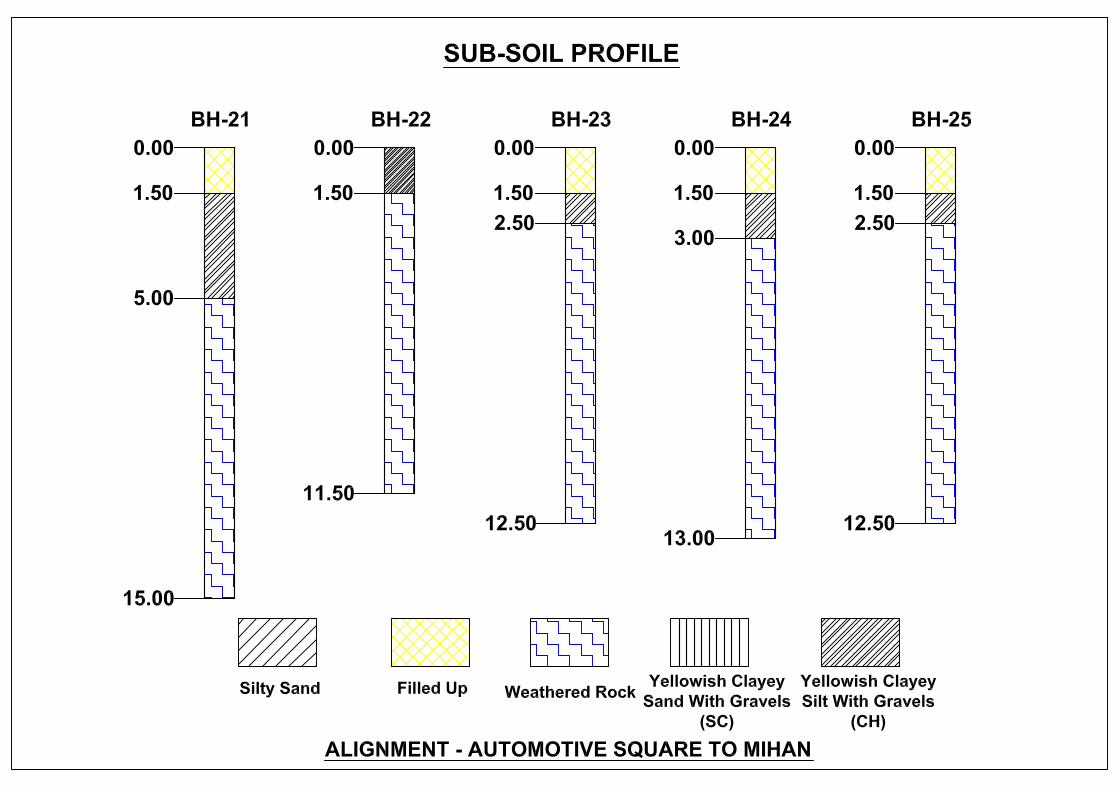
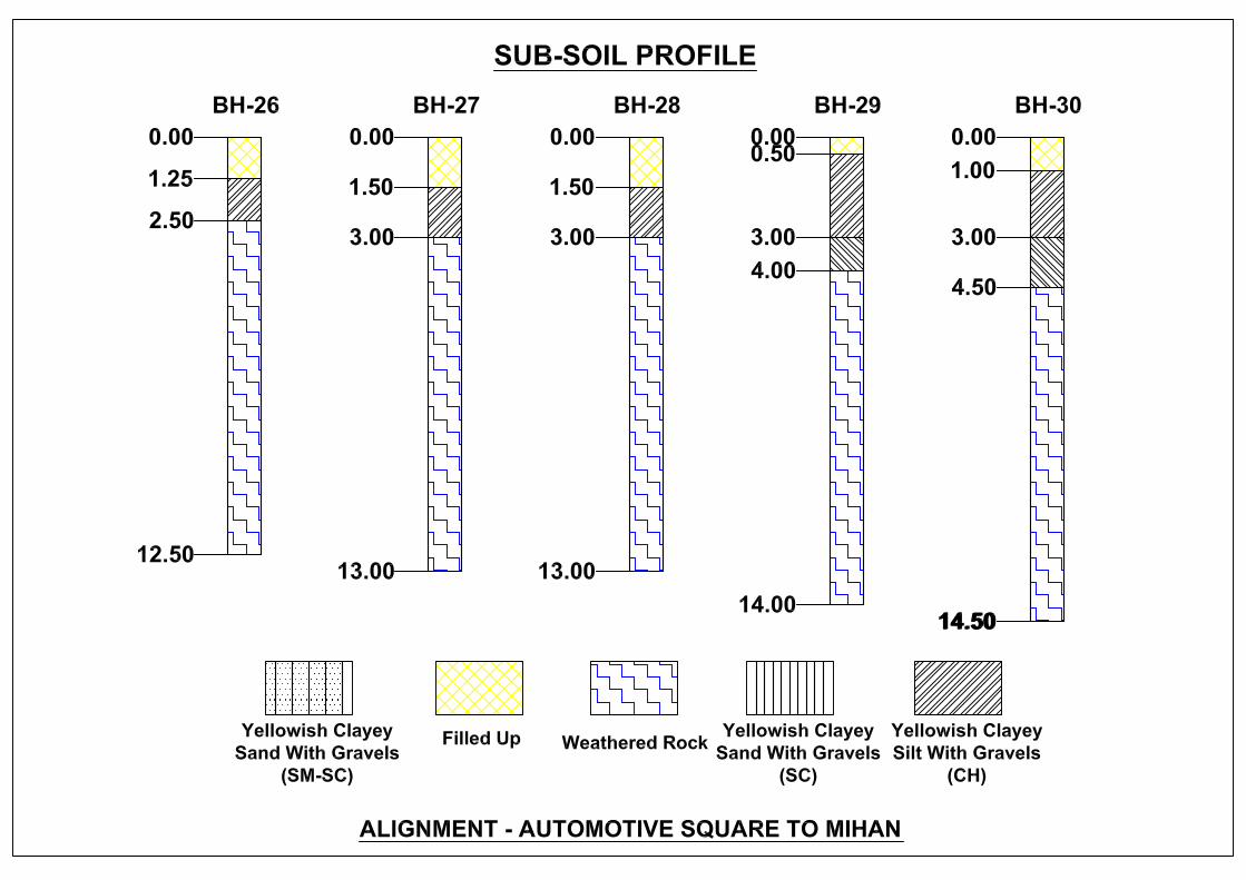
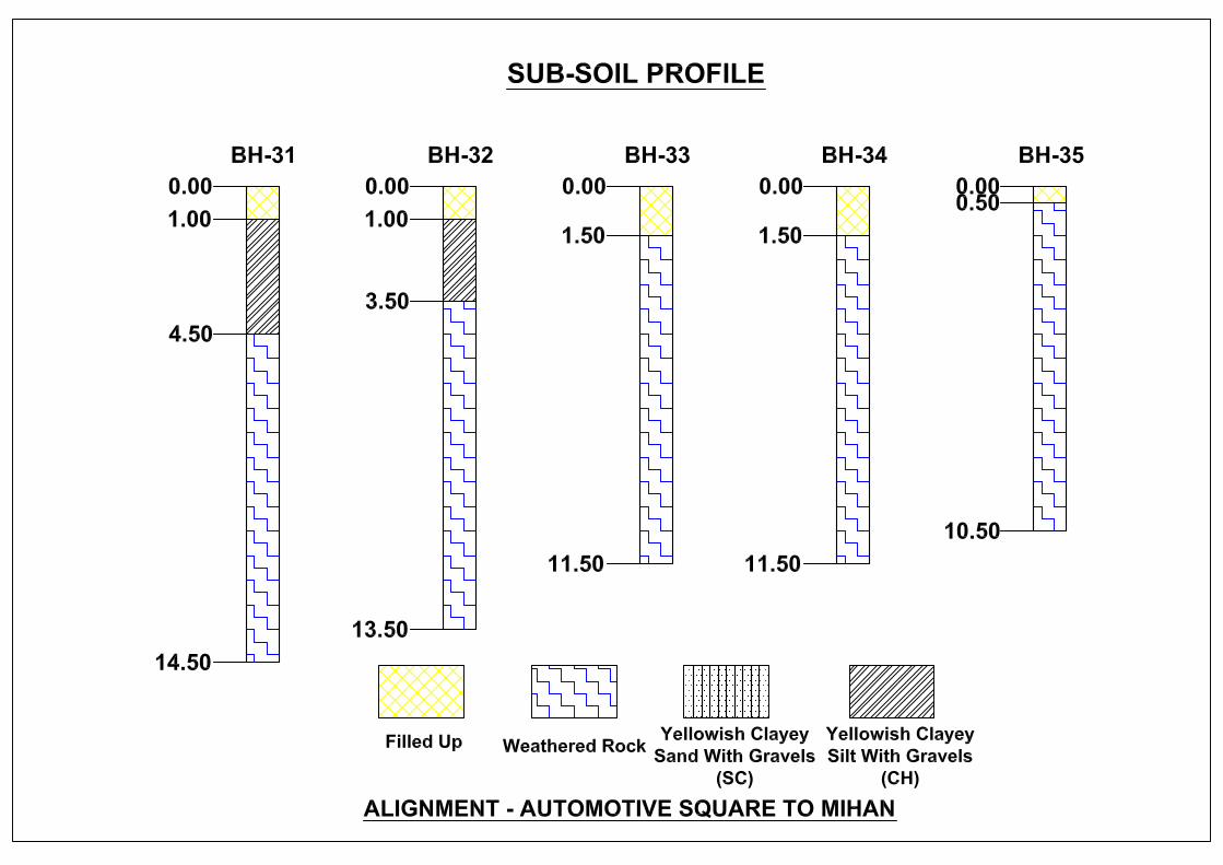
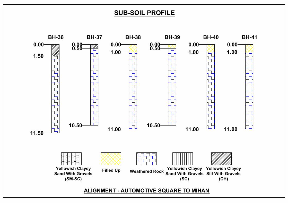
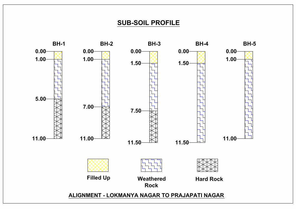
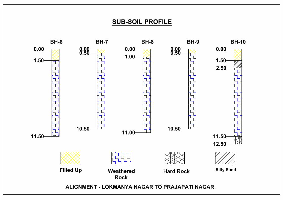
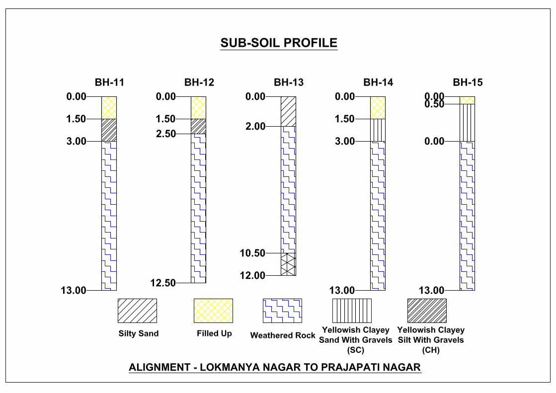
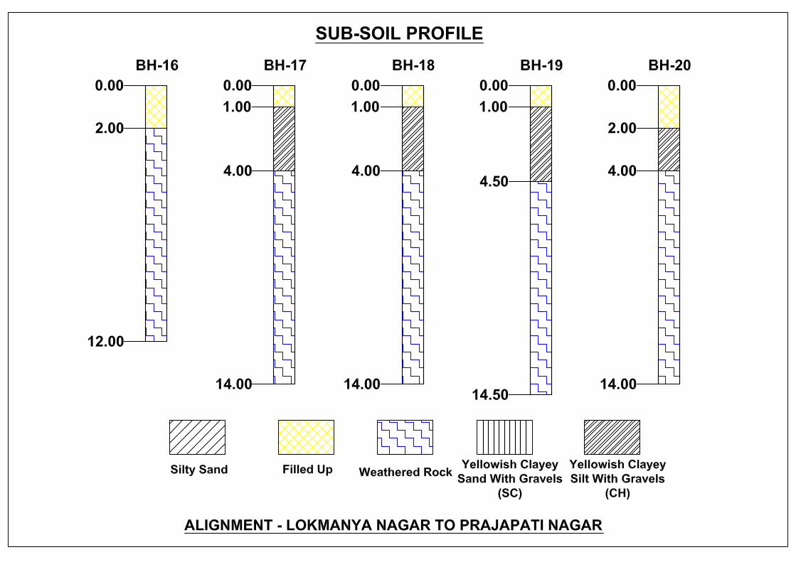
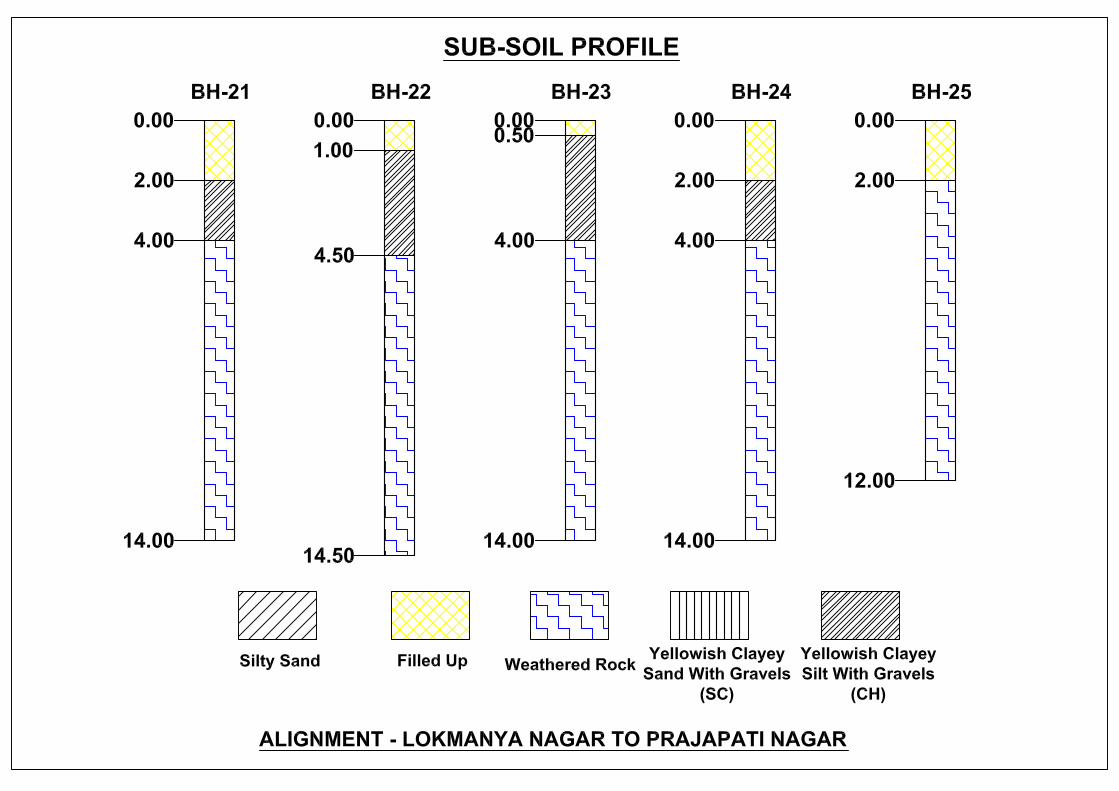
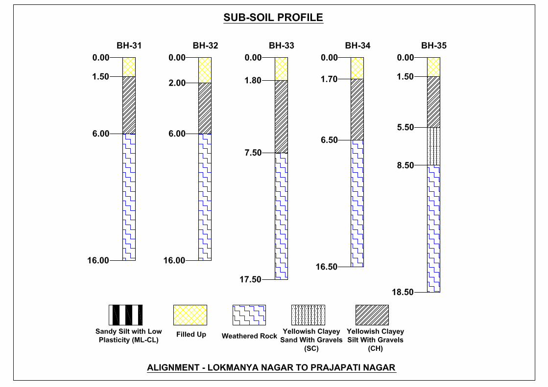
5.7.2 General Geology and Related Characteristics The Geo technical site investigation carried out from AUTOMOTIVE SQUARE TO MIHANalignment & 39 boreholes were driven in Lokmanya Nagar to Prajapati Nagar alignment with in the Nagpur City of Maharashtra.
Nagpur lies on the Deccan plateau of the Indian Peninsula and has a mean altitude of 310.5 meters above sea level. The underlying rock strata are covered with alluvial deposits resulting from the flood plain of the Kanhan River. In some places these give rise to granular sandy soil. In low lying areas which are poorly drained, the soil is alluvial clay with poor permeability characteristics. In the eastern part of city crystalline metamorphic rocks such as gneiss, schist and granites are found, while in the northern part yellowish sand stones and clays of the lower Gondwana formations are found.

Chapter 05: Civil Engineering
14/56 DETAILED PROJECT REPORT FOR NAGPUR METRO RAIL PROJECT NOV 2013
Latitude 78015’ to 80045’E, Longitude 18045’ to 21’35’N Physiography and Climate: The city is generally having warm tropical climate with the temperature in summer varying between 410C to 480C and in winter between 320C to 370C. The period between January to April and Nov to December is generally dry whereas in June to October it is rainy season. The city has an average annual rainfall of 1112.0 mm. SEISMICITY : According to studies, Nagpur region lies in between Zone 1 and Zone 2 of Earthquake Zones in the country. It means that Nagpur has close to zero chances of getting a major earthquake which may cause huge devastation. Recent history also supports the fact that Nagpur region is relatively very safe as far as earthquakes are concerned. Though city has not recorded any seismic activity of magnitude above 4 on Richter scale since 1938 and falls under safest earthquake zone area, the possibilities of a low to moderate earthquake cannot be ruled out completely. A study of active faults conducted by the Geological Survey of India (GSI), central region in city in last ten years, has shown presence of predominant features of neo-tectonic activity in vicinity (200 plus km) of Nagpur which could reactivate and trigger low to moderate quakes in the area. Active faults studies conducted by GSI department from 2002 to March 2012 has shown that the entire stretch starting from Shadol district in Madhya Pradesh in the Son river basin to Narmada banks in Jabalpur, the Son Narmada South Fault (SNSF) which continues westward to become Gwaligarh fault (north of Paratwada in Maharashtra) has shown presence of proterozoic metamorphic rocks along the banks of the rivers which are known for tectonic activity

Chapter 05: Civil Engineering
15/56 DETAILED PROJECT REPORT FOR NAGPUR METRO RAIL PROJECT NOV 2013
GEOGRAPHY: The Nagpur region has complex topography of hilly terrain, undulating terrain & plains. Nearly 40% area is occupied by forests having hilly terrains. The Wardha, Wainganga, Painganga, Pranhita, Indravati rivers are forming major basins in the area. The drainage pattern is dendritic to sub parallel. GEOLOGY: The geology of the Nagpur region is famous for the metamorphic rocks, which occur in all the districts in the Nagpur region except Wardha and some part of Nagpur district. The other geological formation Deccan Traps occur in the Wardha and North and North-West part of Nagpur District. The stratigraphic succession of the geologic formations in the region is given below.
Stratigraphy of the rock types occurring in the Nagpur Region
Table 5.1: ROCK TYPES Age Rock Type Geology Geographical distribution in
Nagpur Region.
Lower Eocene to Upper cretaceous Igneous Rocks
Deccan Trap, Volcanic lava flows with inter trappean beds.
Wardha and Some parts of Nagpur district & Chandrapur.
Lamatas and Bagh Beds Parts of Nagpur. Jurrassic upper Gondwana Metamorphic Chikiala & Kota stages. Lime stone Sironcha taluka of Gadchiroli
district.
Triassic Sedimentary Rocks
Pachmari & Maler’s stages – Clays, Sandstones.
Sironcha taluka of Gadchiroli district.
Permian Lower Gondwana
Sedimentary Rocks
Mangli Beds – Sandstone Warora Taluka of Chandrapur district.
Kamptee series – Sandstone, Shale, Coal Nagpur & Chandrapur district.
Barakar Series – Sandstone, Shales and Coal. Nagpur & Chandrapur district.
Upper Carboniferrous
Metamorphic Rocks
Talchir series – Boulders, Green shale, Sand stones, Shales, Clays) Nagpur & Chandrapur district.
Proterozoic Sedimentary Rocks
Vindhyan super group (Lime stones, Shales & Sandstones) Chandrapur district.
Cuddapah equivalent Limestones & shales
Sironcha Taluka of Gadchiroli district.
Precambrian Metamorphic Rocks
Sakoli Series Quartzites schists,Phyllites, Iron ore series Quartzites schists,Phyllites,
Gadchiroli, Chandrapur, Nagpur & Bhandara districts.
Sausar Series Marbles gneisses,schists granite Nagpur & Bhandara districts.
Penisular Basement complex (Archeans) Gneisses, schists,Granites
Gadchiroli, Chandrapur, Nagpur and Bhandara Districts

Chapter 05: Civil Engineering
16/56 DETAILED PROJECT REPORT FOR NAGPUR METRO RAIL PROJECT NOV 2013
5.7.3 FIELD INVESTIGATION
Field Investigation at the site were planned to determine the required strength characteristics of the underlying soil/rock strata to design the foundations of the proposed structure to be constructed. The geotechnical investigation work includes:
1. Drilling of 150mm diameter boreholes in all kind of soil including gravels and cobbles and Nx size borehole in boulders and rock strata. All boreholes shall be extend upto depths of 30 m in soil (up to N>=100) or 10 m in weathered rock (RQD <=50%) or 5 m in hard rock (RQD>50%).
However the maximum depth of bore hole does not exceed 30 m. If strata having a standard Penetration Test value greater than 100 with characteristics of rock are met earlier, the borehole shall not be advanced further. When the boreholes are to be terminated in soil strata, the Standard Penetration Test shall be carried out at the termination depth and recorded.
2. Conducting Standard penetration test (SPT) at every 1.5m interval starting from 1.5m from natural ground level or every change of stratum as per IS:2131.
3. Collection of disturbed, undisturbed soil samples and water sample as per IS: 2132, IS: 1892 & IS: 3025 should be followed.
4. The following laboratory tests were conducted on collected soil/water samples.
Table 5.2 :LABORATORY TESTS-SOIL/WATER
SL. NO.
PARTICULARS OF PROPERTIES DISTURBED SOIL SAMPLE
UNDISTURBED SOIL SAMPLES
1. Sieve Analysis √ √
2. Hydrometer Analysis √ √
3. Natural Moisture Content √
4. Bulk / Dry Density √
5. Specific Gravity √ √
6. Atterberg’s Limit √ √
7. Direct Shear Test (for non cohesive soils) √
8. UU Tests (for cohesive samples) √
9. UCS Tests (for cohesive samples) √
10. Field permeability test in soil √
11. Chemical test on soil & water sample for pH value, carbonate, sulphate (SO3 and So4)
√

Chapter 05: Civil Engineering
17/56 DETAILED PROJECT REPORT FOR NAGPUR METRO RAIL PROJECT NOV 2013
5. The following laboratory tests were conducted on collected rock sample
Table 5.3 : LABORATORY TESTS/ROCK SAMPLES
SL. NO. PARTICULARS OF PROPERTIES
1. Permeability test by Packer method
2. Density Test
3. Water absorption
4. Porosity
5. Hardness
6. Atterberg’s Limit
7. Unconfined compression test
8. Point load index
9. Modulus of elasticity
10. Abrasion Testing
5.7.4 DETAILS OF GEOTECHNICAL INVESTIGATION 5.7.4.1 GENERAL
Six boring rigs were deployed with all requisite equipments and accessories at project sites. Total 80 boreholes have been drilled at an average distance of 0.5 km each, all along the length of the proposed Metro corridor. 41 bore holes were driven in AUTOMOTIVE SQUARE TO MIHANalignment & 39 boreholes were driven in Lokmanya Nagar to Prajapati Nagar alignment. However, due to the site condition, depth of drilling work ranging from 10.50m to 25m was carried out at the proposed locations. Details of Boreholes are given below in Table no 5.4 & Table no 5.5
5.7.4.2 DETAILS FOR NORTH – SOUTH CORRIDOR
Necessary plant, equipment and personnel for conducting the requisite field work were mobilized to the site. These were shifted from one test location to another location during execution of the field work and demobilized on satisfactory completion of the entire field work.
Chapter 05: Civil Engineering
18/56 DETAILED PROJECT REPORT FOR NAGPUR METRO RAIL PROJECT NOV 2013
Forty one bore holes (BH-1 to BH-41) carried out.
The bore holes were bored at the site using Rotary drilling method as per IS: 1892-1979. Casing as required was used to retain the bore holes. Standard penetration tests were conducted in the above bore holes at every 1.50 m interval & at change of strata as per specifications. The bores were cleaned up to the desired depths. Standard split spoon sampler attached to lower end of ‘A’ drill rods was driven in the bore holes by means of standard hammer of 63.50 Kg falling freely from a height of 75 cm. The sampler was driven 45 cm as per specifications & the numbers of blows required for each 15 cm penetration were recorded. The numbers of blows for the first 15 cm penetration were not taken into account. This was considered as seating drive. The numbers of blows for next 30 cm penetration were designated as SPT ‘N’ value. Wherever the total penetration was less than 45 cm, the number of blows & the depth penetrated is incorporated in respective bore logs. Disturbed soil samples obtained from standard split spoon sampler for all the above standard penetration tests were collected in polythene bags of suitable size. These samples were properly sealed, labelled, recorded and carefully transported to the laboratory for testing.
Undisturbed soil samples were collected from the bore holes at every 3.0 m interval in depth & at change of strata as per sampling specifications, in thin walled sampling tubes of 100 mm dia and 450 mm length fitted to an adopter with ball and socket arrangement. These sampling tubes after retrieval from the bore holes were properly waxed and sealed at both ends. These were carefully labeled and transported to the laboratory for testing. Undisturbed soil samples wherever slipped during lifting, were duly marked in the field bore logs as well as in the soil profile.
Disturbed soil samples were also collected from the bore holes at suitable depths/intervals to supplement the boring records. These samples were collected in polythene bags of suitable size. These samples were properly sealed, labeled, recorded & carefully transported to the laboratory for testing.
Conducting field permeability test in same bore holes in overburden using falling head and in rock with packer.
The depth of ground water table was checked / measured in all bore holes. The ground water table was encountered in some bore holes during the boring activity

Chapter 05: Civil Engineering
19/56 DETAILED PROJECT REPORT FOR NAGPUR METRO RAIL PROJECT NOV 2013
Summary of Bore Holes for this corridor is as below :
Table 5.4 – SUMMARY OF BORE HOLES N.S.CORRIDOR
BH No. Location Details Total
depth Soil Soft Rock
Hard Rock
Water Table (m)
1 Automative Chowk 25.00 15.00 10.00 - 7.20 2 Go Gas Pump 16.50 6.50 10.00 - 7.10 3 kailly Automobiles 17.00 7.00 10.00 - 7.20 4 Lal godown chowk 15.50 5.50 10.00 - 6.00 5 New Indira Hindi School 16.00 6.00 10.00 - 6.90 6 Oppt. Jaswant Tuli Mall, 16.00 6.00 10.00 - 7.10 7 Bharat Petrol Pump (10 No. Pulia) 14.50 4.50 10.00 - 5.40 8 Kadwii Chowk, 14.50 4.50 10.00 - 5.15 9 Gurudwara (Railway Line Near) 20.00 10.00 10.00 - 5.00 10 Gaddi Godown Chowk 12.00 2.00 10.00 - 4.25 11 L.I.C Chowk, AHM Church Campus 11.50 1.50 10.00 - 4.40 12 R.B.I Bank Chowk 12.00 2.00 10.00 - 4.00 13 Morrises Collage, T. Point 11.00 1.00 10.00 - 3.85 14 Sita Burdi Police Station 14.50 4.50 10.00 - 5.00 15 Ras Furniture, Oppt. Nangle Traders 16.00 6.00 10.00 - 4.70 16 Yaswant Stadium 17.00 7.00 10.00 - 4.60 17 Dhantoli P.S, Oppt. Green City Hotel 17.50 7.50 10.00 - 5.10 18 Madhukar Arts (M. Printers) 15.00 5.00 10.00 - 3.20 19 Asha Towers 14.50 4.50 10.00 - 3.90 20 Hardikar Chowk 14.00 4.00 10.00 - 3.40 21 Central Jail 15.00 5.00 10.00 - 3.60 22 Clock Tower Rajive Gandhi Chowk 11.50 1.50 10.00 - 3.25 23 Sanskar Vidhya Sagar School 12.50 2.50 10.00 - 4.00 24 Bharat Creations/Sanjay Traders 13.00 3.00 10.00 - 4.10 25 Sawarkar Chowk 12.50 2.50 10.00 - 2.90 26 Khamla Bus Stop 12.50 2.50 10.00 - 3.60 27 Baba Hardware/Vijay Trading 13.00 3.00 10.00 - 3.00 28 Arun Rao Purnakar Chowk (Puliya) 13.00 3.00 10.00 - 2.10 29 Park/Dence Forest Area (Airport) 14.00 4.00 10.00 - 2.90 30 Parking Airport 14.50 4.50 10.00 - 2.10 31 Airport Boundry 14.50 4.50 10.00 - 3.70 32 Mihan Entry 13.50 3.50 10.00 - 2.65 33 Mihan Road 11.50 1.50 10.00 - 2.50 34 Mihan Road 11.50 1.50 10.00 - 3.70 35 Mihan Road 10.50 0.50 10.00 - 3.20 36 Mihan Road 11.50 1.50 10.00 - 3.15 37 Mihan Road 10.50 0.50 10.00 - 3.20 38 Mihan Road 11.00 1.00 10.00 - 4.05 39 Mihan Road 10.50 0.50 10.00 - 4.00 40 Mihan Depot 11.00 1.00 10.00 - 3.10 41 Mihan Depot 11.00 1.00 10.00 - 2.40
Chapter 05: Civil Engineering
20/56 DETAILED PROJECT REPORT FOR NAGPUR METRO RAIL PROJECT NOV 2013
5.7.4.3 DETAILS FOR EAST - WEST CORRIDOR Thirty nine bore holes (BH-1 to BH-39) were carried out. The bore holes were bored at this site using Rotary drilling method as per IS: 1892-1979. Casing as required was used to retain the bore holes.
Standard penetration tests were conducted in the above bore holes at every 1.50 m interval & at change of strata as per specifications. The bores were cleaned up to the desired depths. Standard split spoon sampler attached to lower end of ‘A’ drill rods was driven in the bore holes by means of standard hammer of 63.50 Kg falling freely from a height of 75 cm. The sampler was driven 45 cm as per specifications & the numbers of blows required for each 15 cm penetration were recorded. The numbers of blows for the first 15 cm penetration were not taken into account. This was considered as seating drive. The numbers of blows for next 30 cm penetration were designated as SPT ‘N’ value. Wherever the total penetration was less than 45 cm, the number of blows & the depth penetrated is incorporated in respective bore logs. Disturbed soil samples obtained from standard split spoon sampler for all the above standard penetration tests were collected in polythene bags of suitable size. These samples were properly sealed, labelled, recorded and carefully transported to the laboratory for testing.
Undisturbed soil samples were collected from the bore holes at every 3.0 m interval in depth & at change of strata as per sampling specifications, in thin walled sampling tubes of 100 mm dia and 450 mm length fitted to an adopter with ball and socket arrangement. These sampling tubes after retrieval from the bore holes were properly waxed and sealed at both ends. These were carefully labeled and transported to the laboratory for testing. Undisturbed soil samples wherever slipped during lifting, were duly marked in the field bore logs as well as in the soil profile.
Disturbed soil samples were also collected from the bore holes at suitable depths/intervals to supplement the boring records. These samples were collected in polythene bags of suitable size. These samples were properly sealed, labeled, recorded & carefully transported to the laboratory for testing.
Conducting field permeability test in same bore holes in overburden using falling head and in rock with packer.
The depth of ground water table was checked / measured in all bore holes. The ground water table was encountered in some bore holes during the boring activity.
Summary of Bore Holes is given in Table : 5.5

Chapter 05: Civil Engineering
21/56 DETAILED PROJECT REPORT FOR NAGPUR METRO RAIL PROJECT NOV 2013
Table 5.5 – SUMMARY OF BORE HOLES E W CORRIDOR
BH No. Location Details Total
depth Soil Soft Rock
Hard Rock
Water Table (m)
1 AIA Engineering Limited. 11.00 1.00 5.00 5.00 3.50 2 C.R.P.F Gate No.-1 11.00 1.00 6.00 4.00 4.20 3 Mahindra Company 11.50 1.50 6.00 4.00 4.30 4 Ambru Batti Chowk (Near Dharam kantta
) 11.50 1.50 10.00 - 4.05
5 Toll Tax Naka 11.00 1.00 10.00 - 4.25 6 Super Enclave, Opp. Prashant Trading 11.50 1.50 10.00 - 5.30 7 Hingna T. Point 10.50 0.50 10.00 - 4.70 8 Karankutti Hotel 11.00 1.00 10.00 - 4.60 9 Pump House (G.C.C.R.P.F) Nagpur. 10.50 0.50 10.00 - 5.10 10 Subhash Nagar Chowk, 12.50 2.50 9.00 1.00 4.20 11 Nagpur Improvement Trust, Crazy Castle. 13.00 3.00 10.00 - 4.40 12 Tanveer Hotel 12.50 2.50 10.00 - 3.40 13 Leela house (Near Ambajhari T.Point) 12.00 2.00 8.50 1.50 3.60 14 L.A.D. Chowk 13.00 3.00 10.00 - 5.10 15 Shankar Nagar chowk 13.00 3.00 10.00 - 5.15 16 Adrash S.S High School 12.00 2.00 10.00 - 5.10 17 Dharampeeth Vidhyalay 14.00 4.00 10.00 - 4.90 18 A.M.I.E (Nagpur Local Center) 14.00 4.00 10.00 - 5.50 19 M.J Collage 14.50 4.50 10.00 - 4.90 20 Jhansi Rani Chowk 14.00 4.00 10.00 - 5.10 21 Munje Chowk 14.00 4.00 10.00 - 5.70 22 Railway Push Box. 14.50 4.50 10.00 - 4.60 23 Nagpur Corporation octroi Naka - 13 14.00 4.00 10.00 - 4.20 24 Hazrat baba majar 14.00 4.00 10.00 - 5.30 25 Mayo Hospital 12.00 2.00 10.00 - 3.90 26 Sewa Sadan Chowk 13.00 3.00 10.00 - 4.50 27 Gandhi Bagh (Bus Stop) 12.50 2.50 10.00 - 4.35 28 Chittarawali Chowk 13.20 3.20 10.00 - 4.70 29 Darodkar Chowk 13.15 3.15 10.00 - 4.60 30 Rahate Hospital 14.50 4.50 10.00 - 4.75 31 Telephone Exchange 16.00 6.00 10.00 - 7.20 32 Chapro Nagar Chowk, Bharat Furniture 16.00 6.00 10.00 - 5.30 33 Ambedkar Chowk, 17.50 7.50 10.00 - 4.90 34 Ali Electrical, Vardhman Nagar Chowk 16.50 6.50 10.00 - 7.40 35 Near Mahalaxmi Collaction 18.50 8.50 10.00 - 6.40 36 Sapna Bar & Restorent 17.00 7.00 10.00 - 4.30 37 Radhe Krishan Hospital Chowk 17.50 7.50 10.00 - 7.30 38 Desi Wine Shop 21.00 10.00 10.00 - 7.60 39 Gomti Hotel, Near P & B Bank 25.00 10.00 10.00 - 7.30

Chapter 05: Civil Engineering
22/56 DETAILED PROJECT REPORT FOR NAGPUR METRO RAIL PROJECT NOV 2013
5.7.4.4 TYPE OF FOUNDATION : TYPE OF FOUNDATION :NORTH – SOUTH CORRIDOR
A : Bored Cast in situ RCC Pile Depending on the field and laboratory observations of subsoil strata, test results and the type of structures proposed at site, the most feasible soil-foundation system is recommended as normal bored cast in situ R.C.C. piles foundations of 0.80m & 1.0m diameter at different depths with cut-off level at 1.50m to 2.0m depth below existing Ground level. The safe load carrying capacities of these piles are given in following table.
Table :5.6 RCC PILE DETAILS FOR NORTH – SOUTH CORRIDOR
Borehole Nos
Dia. of Pile
Cutoff level Depth, m
Pile Capacity Compressio
n Uplift Lateral
1 0.80 1.50 19.00 185.0 90.0 9.0 1.00 1.50 19.00 300.0 120.0 12.0
2, 3 0.80 1.50 11.00 170.0 40.0 9.0 1.00 1.50 11.00 250.0 50.0 12.0
4,5,6 0.80 1.50 10.50 170.0 45.0 9.0 1.00 1.50 10.50 250.0 50.0 12.0
7,8 0.80 1.50 10.00 150.0 35.0 9.0 1.00 1.50 10.00 225.0 45.0 12.0
9 0.80 1.50 15.00 220.0 85.0 9.0 1.00 1.50 15.00 320.0 100.0 12.0
14 0.80 1.50 10.00 150.0 35.0 9.0 1.00 1.50 10.00 225.0 45.0 12.0
15,16 0.80 1.50 11.00 170.0 40.0 9.0 1.00 1.50 11.00 250.0 50.0 12.0
17 0.80 1.50 12.00 180.0 45.0 9.0 1.00 1.50 12.00 260.0 55.0 12.0
18 to 21 0.80 1.50 10.00 150.0 35.0 9.0 1.00 1.50 10.00 225.0 45.0 12.0
23 to 28 0.80 1.50 10.00 140.0 33.0 9.0 1.00 1.50 10.00 210.0 40.0 12.0
29 to 32 0.80 1.50 10.00 150.0 35.0 9.0 1.00 1.50 10.00 225.0 45.0 12.0
Chapter 05: Civil Engineering
23/56 DETAILED PROJECT REPORT FOR NAGPUR METRO RAIL PROJECT NOV 2013
Note: 1. For design purpose, water table shall be considered at cut off level. 2. For design purpose, effective overburden pressure at pile tip should correspond
to pile length equal to 15 times the diameter. 3. The above values should be confirmed through pile load tests in the field before
adopting these values for design purposes.
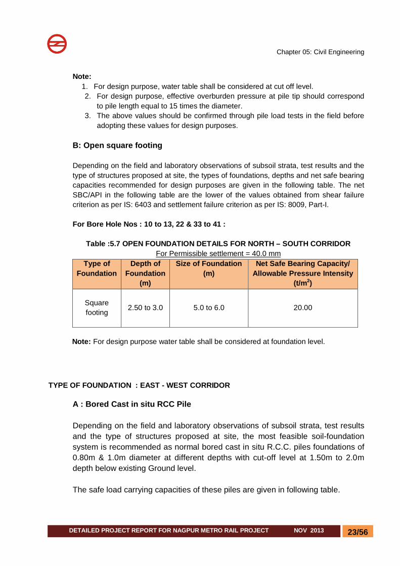
B: Open square footing Depending on the field and laboratory observations of subsoil strata, test results and the type of structures proposed at site, the types of foundations, depths and net safe bearing capacities recommended for design purposes are given in the following table. The net SBC/API in the following table are the lower of the values obtained from shear failure criterion as per IS: 6403 and settlement failure criterion as per IS: 8009, Part-I. For Bore Hole Nos : 10 to 13, 22 & 33 to 41 :
Table :5.7 OPEN FOUNDATION DETAILS FOR NORTH – SOUTH CORRIDOR
For Permissible settlement = 40.0 mm Type of
Foundation
Depth of Foundation
(m)
Size of Foundation (m)
Net Safe Bearing Capacity/ Allowable Pressure Intensity
(t/m2)
Square footing 2.50 to 3.0 5.0 to 6.0 20.00
Note: For design purpose water table shall be considered at foundation level.
TYPE OF FOUNDATION : EAST - WEST CORRIDOR
A : Bored Cast in situ RCC Pile Depending on the field and laboratory observations of subsoil strata, test results and the type of structures proposed at site, the most feasible soil-foundation system is recommended as normal bored cast in situ R.C.C. piles foundations of 0.80m & 1.0m diameter at different depths with cut-off level at 1.50m to 2.0m depth below existing Ground level. The safe load carrying capacities of these piles are given in following table.
Chapter 05: Civil Engineering
24/56 DETAILED PROJECT REPORT FOR NAGPUR METRO RAIL PROJECT NOV 2013
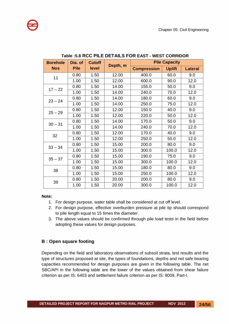
Table :5.8 RCC PILE DETAILS FOR EAST - WEST CORRIDOR Borehole
Nos Dia. of
Pile Cutoff level Depth, m
Pile Capacity Compression Uplift Lateral
11 0.80 1.50 12.00 400.0 60.0 9.0 1.00 1.50 12.00 600.0 90.0 12.0
17 – 22 0.80 1.50 14.00 155.0 50.0 9.0 1.00 1.50 14.00 240.0 70.0 12.0
23 – 24 0.80 1.50 14.00 180.0 60.0 9.0 1.00 1.50 14.00 250.0 75.0 12.0
25 – 29 0.80 1.50 12.00 150.0 40.0 9.0 1.00 1.50 12.00 220.0 50.0 12.0
30 – 31 0.80 1.50 14.00 170.0 50.0 9.0 1.00 1.50 14.00 240.0 70.0 12.0
32 0.80 1.50 12.00 170.0 40.0 9.0 1.00 1.50 12.00 250.0 50.0 12.0
33 – 34 0.80 1.50 15.00 200.0 80.0 9.0 1.00 1.50 15.00 300.0 100.0 12.0
35 – 37 0.80 1.50 15.00 190.0 75.0 9.0 1.00 1.50 15.00 300.0 100.0 12.0
38 0.80 1.50 15.00 180.0 80.0 9.0 1.00 1.50 15.00 250.0 100.0 12.0
39 0.80 1.50 20.00 200.0 80.0 9.0 1.00 1.50 20.00 300.0 100.0 12.0
Note:
1. For design purpose, water table shall be considered at cut off level. 2. For design purpose, effective overburden pressure at pile tip should correspond
to pile length equal to 15 times the diameter. 3. The above values should be confirmed through pile load tests in the field before
adopting these values for design purposes.
B : Open square footing Depending on the field and laboratory observations of subsoil strata, test results and the type of structures proposed at site, the types of foundations, depths and net safe bearing capacities recommended for design purposes are given in the following table. The net SBC/API in the following table are the lower of the values obtained from shear failure criterion as per IS: 6403 and settlement failure criterion as per IS: 8009, Part-I.

Chapter 05: Civil Engineering
25/56 DETAILED PROJECT REPORT FOR NAGPUR METRO RAIL PROJECT NOV 2013
Table :5.9 OPEN FOUNDATION DETAILS FOR EAST-WEST CORRIDOR For Permissible settlement = 40.0 mm
Type of Foundatio
n
B/Hole No
Depth of Foundatio
n (m)
Size of Foundation
(m)
Net Safe Bearing Capacity/ Allowable Pressure Intensity
(t/m2)
Square footing
1 – 9 2.50 - 3.0 5.0 to 6.0 25.00
10 & 12 3.0 5.0 to 6.0 20.00
12 – 13 3.0 5.0 to 6.0 20.00
14 – 15 3.00 - 4.00 5.0 to 6.0 25.00
16 3.0 5.0 to 6.0 20.00 Note: For design purpose water table shall be considered at foundation level.
5.8 LAND
5.8.1 The alignment and profile
Both the alignments are elevated except around 4.6 Km at Grade alignment. Total 36 stations are proposed in both corridors, Out of which 02 are at grade and 35 are elevated.
5.8.2 Land Requirement for following Major Components
MRTS Structure (including Route Alignment), Station Building, Platforms, Entry/Exit Structures, Traffic Integration Facilities, Depots, etc. Receiving/Traction Sub-stations Radio Towers Temporary Construction Depots and work sites. Staff quarters, office complex and operation control centre(OCC)
5.8.3 Land for Underground stretches No land at surface is required permanently for underground section, except for small areas for entry/exit structures, traffic integration, chilling plant and ventilation shafts at stations. These will be located either on footpath edge or in front marginal open setback of the building along the road.
5.8.4 Land required for elevated stretches For elevated section, single pier supporting the viaduct will be located on the middle of road so that the existing roads remain in use as usual. Accordingly, necessary
Chapter 05: Civil Engineering
26/56 DETAILED PROJECT REPORT FOR NAGPUR METRO RAIL PROJECT NOV 2013
permission for using such right-of-way will have to be obtained from the concerned authorities. Elevated station is generally proposed with elevated concourse so that land is required only for locating the entry/exit structures. Traffic integration facilities are provided wherever the same are required and, but no land is proposed for acquisition. The normal viaduct structure of elevated Metro is about 10 m (edge to edge) wide. Ideally the required right of way is 10m. However, for reasons of safety a clean marginal distance / setback of about 5 m is necessary from either edge of the viaduct (or 10 m on both sides of the centre line) wherein no structures are to be located. This is necessary as the traction system as proposed is overhead 25 kV ac systems with masts fixed on the parapets. Also, it ensures road access and working space all along the viaduct for working of emergency equipments and fire brigade. In stretches, where the elevated alignment has to be located away from road, a strip of 20-m width is proposed for acquisition.
5.8.5 Land for Switch-over Ramps Switch-over ramps are required for transition from the underground to elevated section or vice versa. The ramp covers a stretch at ground for the whole width of structure for two tracks (about 10.5m including the protection works). The length of ramp above ground depends on the existing ground slope and the gradient provided on Metro alignment (normally 3% to 4%). Thus the ramp is to be located in an area where sufficient road width is available or in an open area. On this corridor, three such ramps are provided on the both the corridors.
5.8.6 Land for Traffic integration Certain land is required for traffic integration at the each station. Efforts have been made to identify land required for traffic integration at each station to facilitate park and ride facility, but it is not possible to find open space at all the locations. Hence land for traffic integration has been marked in the drawing wherever is available.
5.8.7 Land for Traction and Receiving Substation and Radio Towers Four RSS are proposed to be located for both the corridors. Hence, an area has to be earmarked at Kasturchand Park. The exact location will be decided at the time of implementation of the project. Similarly, four radio towers are also being proposed to be located at four locations occupying an area of 100 m2 (10 m X 10 m each plot) for each radio tower.

Chapter 05: Civil Engineering
27/56 DETAILED PROJECT REPORT FOR NAGPUR METRO RAIL PROJECT NOV 2013
5.8.8 Land Requirement for Stations & Running section The station is generally located on the road median. Total length of the station is ~140m. All the stations are two-level stations. The concourse is planned along the whole length of the platform with staircases leading from either side of the road. The maximum width of the station at concourse is ~22m. Passenger facilities like ticketing, information, etc as well as operational areas are provided at the concourse level. The staircase giving access to concourse area from ground will be located at the edge of footpaths or in front marginal open setback of the buildings in the as far as possible in the open space. Nevertheless it is not possible to find open space at all the locations therefore acquisition of certain private structures is inevitable. At curved portions, the alignment could not be kept in the centre of the road and land acquisition at such locations is inevitable in spite of introduction of sharper curves. To the extent possible the Entry and Exit points of stations (underground and elevated) were planned on the foot paths. But, for locating other station facilities such as chiller plants, ventilation shafts, underground water tanks, generator set room etc., land acquisition is proposed The details of land permanently required for depot, running sections and stations are indicated in the Table 5.10, Table 5.10 A, 5.10 C, 5.10 D and Table 5.10E.
Table 5.10: Details of Land Required for Depot
S. No. Plot No. Location Area (approx) Ownership Purpose
1. DP1 KHAPRI 33.90 hectares Government Depot
2. DP2 SRP LAND 25.89 hectares Government Depot
Table 5.10 A: Details of Land Required for Running Section
EAST-WEST CORRIDOR EATS-WEST CORRIDOR
S.NO PLOT NO AREA(Sqm) OWNERSHIP 1 RS-1 82 Govt. 2 RS-2 215.8 Pvt. 3 RS-3 34.7 Govt. 4 RS-4 1930.3 Pvt. 5 RS-5 129.5 Pvt. 6 RS-6 86.8 Pvt. 7 RS-7 25.8 Pvt. 8 RS-8 590.9 Pvt. 9 RS-9 2594.8 Govt.
10 RS-10 543.8 Govt. 11 RS-11 923.9 Pvt. 12 RS-12 550.5 Pvt.

Chapter 05: Civil Engineering
28/56 DETAILED PROJECT REPORT FOR NAGPUR METRO RAIL PROJECT NOV 2013
EATS-WEST CORRIDOR S.NO PLOT NO AREA(Sqm) OWNERSHIP
13 RS-13 584.9 Pvt. 14 RS-14 278.4 Pvt. 15 RS-15 40.3 Pvt. 16 RS-16 229.1 Pvt. 17 RS-17 11.6 Pvt. 18 RS-18 22.1 Pvt. 19 RS-19 14.7 Pvt. 20 RS-20 1.8 Pvt. 21 RS-21 4.8 Pvt. 22 RS-22 34.8 Pvt. 23 RS-23 0.9 Pvt. 24 RS-24 3.9 Pvt.
Total Land = 8936.1Sqm Govt. = 3255.3 Sqm. Pvt. =5680.8Sqm.
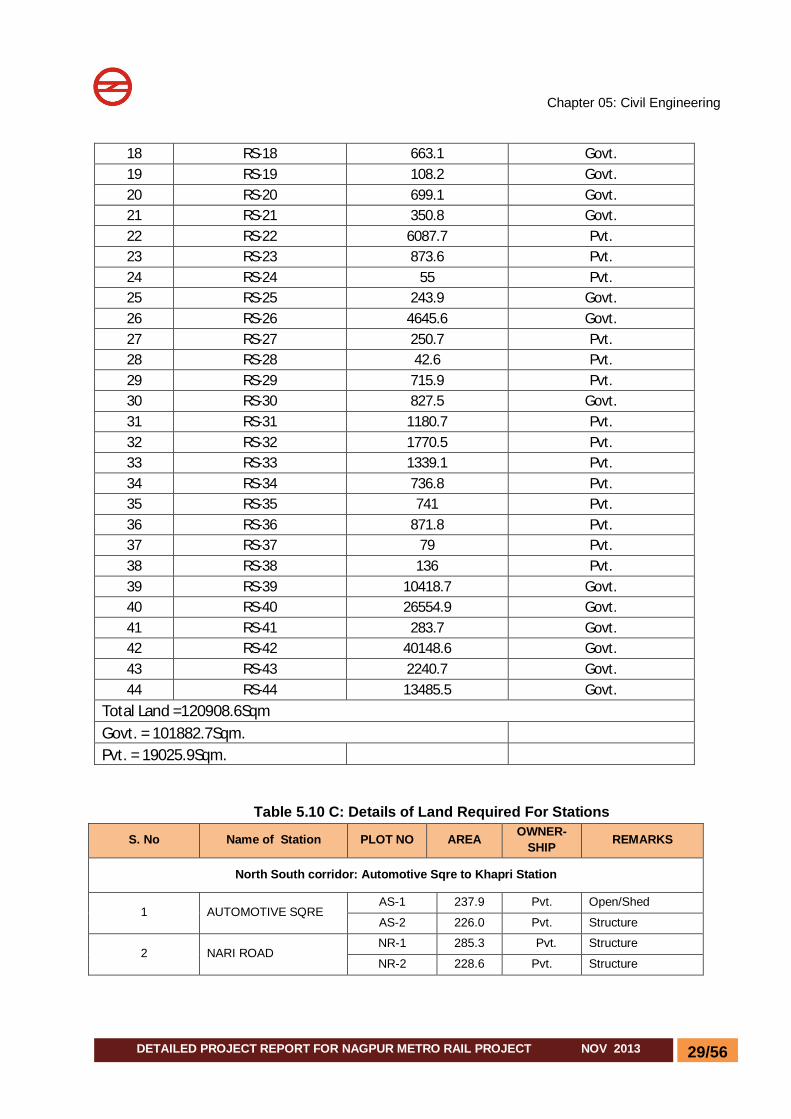
Table 5.10 B: Details of Land Required for Running Section NORTH SOUTH CORRIDOR
RUNNING SECTION OF NAGPUR METRO RAIL PROJECT NORTH-SOUTH CORRIDOR
S.NO PLOT NO AREA(Sqm) OWNERSHIP 1 RS-1 35.3 Pvt. 2 RS-2 108.8 Pvt. 3 RS-3 11.3 Govt. 4 RS-4 1.9 Pvt. 5 RS-5 55.1 Pvt. 6 RS-6 60.9 Pvt. 7 RS-7 53.1 Govt. 8 RS-8 198.6 Govt. 9 RS-9 152.4 Govt.
10 RS-10 31.5 Pvt. 11 RS-11 25.3 govt. 12 RS-12 29.1 govt. 13 RS-13 105.6 Pvt. 14 RS-14 3746.4 Pvt. 15 RS-15 553.1 Govt. 16 RS-16 67.4 Govt. 17 RS-17 122.1 Govt.
Chapter 05: Civil Engineering
29/56 DETAILED PROJECT REPORT FOR NAGPUR METRO RAIL PROJECT NOV 2013
18 RS-18 663.1 Govt. 19 RS-19 108.2 Govt. 20 RS-20 699.1 Govt. 21 RS-21 350.8 Govt. 22 RS-22 6087.7 Pvt. 23 RS-23 873.6 Pvt. 24 RS-24 55 Pvt. 25 RS-25 243.9 Govt. 26 RS-26 4645.6 Govt. 27 RS-27 250.7 Pvt. 28 RS-28 42.6 Pvt. 29 RS-29 715.9 Pvt. 30 RS-30 827.5 Govt. 31 RS-31 1180.7 Pvt. 32 RS-32 1770.5 Pvt. 33 RS-33 1339.1 Pvt. 34 RS-34 736.8 Pvt. 35 RS-35 741 Pvt. 36 RS-36 871.8 Pvt. 37 RS-37 79 Pvt. 38 RS-38 136 Pvt. 39 RS-39 10418.7 Govt. 40 RS-40 26554.9 Govt. 41 RS-41 283.7 Govt. 42 RS-42 40148.6 Govt. 43 RS-43 2240.7 Govt. 44 RS-44 13485.5 Govt.
Total Land =120908.6Sqm Govt. = 101882.7Sqm.
Pvt. = 19025.9Sqm.
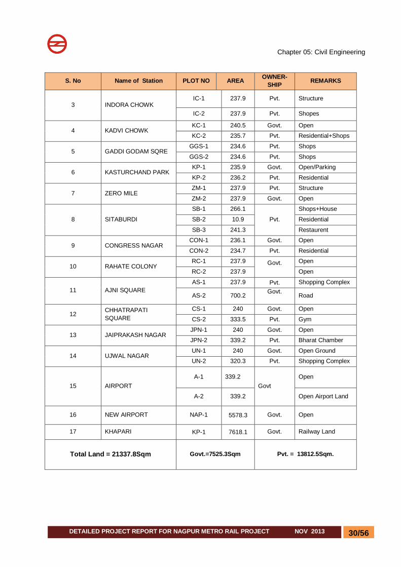
Table 5.10 C: Details of Land Required For Stations
S. No Name of Station PLOT NO AREA OWNER-SHIP REMARKS
North South corridor: Automotive Sqre to Khapri Station
1 AUTOMOTIVE SQRE AS-1 237.9 Pvt. Open/Shed
AS-2 226.0 Pvt. Structure
2 NARI ROAD NR-1 285.3 Pvt. Structure
NR-2 228.6 Pvt. Structure
Chapter 05: Civil Engineering
30/56 DETAILED PROJECT REPORT FOR NAGPUR METRO RAIL PROJECT NOV 2013
S. No Name of Station PLOT NO AREA OWNER-SHIP REMARKS
3 INDORA CHOWK IC-1 237.9 Pvt. Structure
IC-2 237.9 Pvt. Shopes
4 KADVI CHOWK KC-1 240.5 Govt. Open
KC-2 235.7 Pvt. Residential+Shops
5 GADDI GODAM SQRE GGS-1 234.6 Pvt. Shops
GGS-2 234.6 Pvt. Shops
6 KASTURCHAND PARK KP-1 235.9 Govt. Open/Parking
KP-2 236.2 Pvt. Residential
7 ZERO MILE ZM-1 237.9 Pvt. Structure
ZM-2 237.9 Govt. Open
8 SITABURDI
SB-1 266.1
Pvt.
Shops+House
SB-2 10.9 Residential
SB-3 241.3 Restaurent
9 CONGRESS NAGAR CON-1 236.1 Govt. Open
CON-2 234.7 Pvt. Residential
10 RAHATE COLONY RC-1 237.9 Govt.
Open
RC-2 237.9 Open
11 AJNI SQUARE AS-1 237.9 Pvt. Shopping Complex
AS-2 700.2 Govt. Road
12 CHHATRAPATI SQUARE
CS-1 240 Govt. Open
CS-2 333.5 Pvt. Gym
13 JAIPRAKASH NAGAR JPN-1 240 Govt. Open
JPN-2 339.2 Pvt. Bharat Chamber
14 UJWAL NAGAR UN-1 240 Govt. Open Ground
UN-2 320.3 Pvt. Shopping Complex
15 AIRPORT A-1 339.2
Govt Open
A-2 339.2 Open Airport Land
16 NEW AIRPORT NAP-1 5578.3 Govt. Open
17 KHAPARI KP-1 7618.1 Govt. Railway Land
Total Land = 21337.8Sqm Govt.=7525.3Sqm Pvt. = 13812.5Sqm.

Chapter 05: Civil Engineering
31/56 DETAILED PROJECT REPORT FOR NAGPUR METRO RAIL PROJECT NOV 2013
S. No Name of Station PLOT NO AREA OWNER-SHIP REMARKS
East West corridor: Prajati Nagar to Lokmanya Nagar
1 PRAJAPATI NAGAR PN-1 270.3 Pvt. Residential
PN-2 276.7 Govt. Open
2 VAISHNO DEVI CHOWK VDC-1 272.9
Pvt. Residential
VDC-2 269.9 Residential+Shops
3 AMBEDKAR CHOWK AC-1 276.6 Govt. Collage+ Residential
AC-2 297.1 Pvt. Shops
4 TELEPHONE EXCHANGE TE-1 271.8
Pvt. Residential+ Shops
TE-2 270.4 Residential
5 CHITAR OLI CHOWK (GANDHI PUTALA)
COC-1 254.1 Pvt.
Residential
COC-2 273.8 Residential+ Shops
6 AGRASEN CHOWK AGC-1 269.8
Pvt. Residential+ Shops
AGC-2 272.5 Petrol Pump+ Structure
7 DOSAR VAISYA CHOWK (MAYO HOSPITAL)
DVC-1 271.7 Pvt. Residential
DVC-2 271.4
8 NAGPUR RAILWAY STATION
NRS-1 280.9 Govt..
School
NRS-2 290.7 Railway land
9 SITABURDI SB (I)-1 298.4
Pvt. Residence SB(1)-2 299.5
10 JHANSI RANI SQRE JRS-1 282.6 Pvt. Residence
JRS-2 282.8 Govt. Open
11 INSTITUTIONS OF ENGINEERS
IOE-1 272.0 Govt. Open
IOE-2 276.3
12 SHANKAR NAGAR SQRE (BANK OF INDIA)
SNS-1 279.2 Govt.
Petrol Pump + Residential
SNS-2 290.4 Residential
13 LAD CHOWK LC-1 409.6
Pvt. Residential LC-2 409.6
14 DHARAMPETH COLLEGE DC-1 276.3 Pvt.
Open DC-2 284.8 Govt
15 SUBHASH NAGAR SN-1 275.5
Govt. Open SN-2 276.9
16 RACHANA(RING RD JNC) R-1 385.4 Govt. Open
R-2 291.5 Pvt. Residential+Shops
17 VASUDEV NAGAR VN-1 308.9 Pvt. Residential
VN-2 290.4 Govt. Open
18 BANSI NAGAR BN-1 409.7
Pvt. Petrol pump
BN-2 291.5 Structure
19 LOKMANYA NAGAR LN-1 276.4 Govt. Open
Chapter 05: Civil Engineering
32/56 DETAILED PROJECT REPORT FOR NAGPUR METRO RAIL PROJECT NOV 2013
S. No Name of Station PLOT NO AREA OWNER-SHIP REMARKS
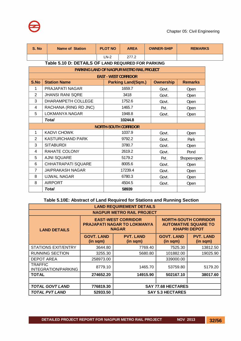
LN-2 277.2
Table 5.10 D: DETAILS OF LAND REQUIRED FOR PARKING PARKING LAND OF NAGPUR METRO RAIL PROJECT
EAST - WEST CORRIDOR S.No Station Name Parking Land(Sqm.) Ownership Remarks
1 PRAJAPATI NAGAR 1659.7 Govt. Open 2 JHANSI RANI SQRE 3418 Govt. Open 3 DHARAMPETH COLLEGE 1752.6 Govt. Open 4 RACHANA (RING RD JNC) 1465.7 Pvt. Open 5 LOKMANYA NAGAR 1948.8 Govt. Open Total 10244.8
NORTH-SOUTH CORRIDOR 1 KADVI CHOWK 1037.9 Govt. Open 2 KASTURCHAND PARK 9792.2 Govt. Park 3 SITABURDI 3780.7 Govt. Open 4 RAHATE COLONY 2619.2 Govt. Pond 5 AJNI SQUARE 5179.2 Pvt. Shopes+open 6 CHHATRAPATI SQUARE 8005.6 Govt. Open 7 JAIPRAKASH NAGAR 17239.4 Govt. Open 8 UJWAL NAGAR 6780.3 Govt. Open 8 AIRPORT 4504.5 Govt. Open
Total 58939
Table 5.10E: Abstract of Land Required for Stations and Running Section LAND REQUIREMENT DETAILS
NAGPUR METRO RAIL PROJECT
LAND DETAILS
EAST-WEST CORRIDOR PRAJAPATI NAGAR TO LOKMANYA
NAGAR
NORTH-SOUTH CORRIDOR AUTOMATIVE SQUARE TO
KHAPRI DEPOT
GOVT. LAND (in sqm)
PVT. LAND (in sqm)
GOVT. LAND (in sqm)
PVT. LAND (in sqm)
STATIONS EXIT/ENTRY 3644.80 7769.40 7525.30 13812.50 RUNNING SECTION 3255.30 5680.80 101882.00 19025.90 DEPOT AREA 258973.00 339000.00 TRAFFIC INTEGRATION/PARKING 8779.10 1465.70 53759.80 5179.20
TOTAL 274652.20 14915.90 502167.10 38017.60 TOTAL GOVT LAND 776819.30 SAY 77.68 HECTARES TOTAL PVT LAND 52933.50 SAY 5.3 HECTARES

Chapter 05: Civil Engineering
33/56 DETAILED PROJECT REPORT FOR NAGPUR METRO RAIL PROJECT NOV 2013
5.8.9 Land Staff quarters, office complex and operation control centre (OCC)
A large number of officers and staff will be required to be deployed permanently to take care of project implementation and post construction operational activities. Moreover metro office complex and metro operation control centre will also be required. It is proposed to keep the provision of 5.0 ha of government land for this purpose. Exact location of land has not been identified at this stage. It may be decided at the time of project implementation.
5.8.10 Temporary Construction Depot/office accommodation
During construction period, huge quantities of construction materials like reinforcing bars, cement, steel sections, shutters, pre-cast segments etc. are to be stored and sufficient land is required for storage of these materials. The areas may be identified based on availability as vacant on date nearer to the corridors. At the time of construction, depending up on the need the location and size can be reassessed and temporary land acquisitions can be made accordingly.
Since the area of land being acquired permanently at most of the stations is bare minimum, the land required for construction depots purpose has been considered throughout the corridor @ 2hect. at every 10 km. These sites will be obtained on lease temporarily for the construction period. After completion of construction, these will be handed over back to the land owning agency. The location of these sites will be finalized with NIT before the commencement of Tendering Work.
5.8.11 Segment Casting Yard
Large numbers of pre-cast segments are required for construction of elevated structures for which a large open area is required for setting up of casting yard. As far as possible, this area should be close to the site, easily accessible and away from habitation. Considering the various factors, it is proposed to setup one yard for both the corridors. It is proposed to setup two segment casting yards one for underground sections and another elevated sections. Provision of 5.0 ha of land for both the casting yards on temporary basis has been made.
5.9 UTILITY DIVERSIONS
5.9.1 Introduction
Besides the details of various aspects e.g. transport demand analysis, route alignment, station locations, system design, viaduct structure, geo-technical investigations etc. as brought out in previous paras, there are a number of other engineering issues, which are
Chapter 05: Civil Engineering
34/56 DETAILED PROJECT REPORT FOR NAGPUR METRO RAIL PROJECT NOV 2013
required to be considered in sufficient details before really deciding on taking up any infrastructure project of such magnitude. Accordingly, following engineering items have been studied and described in this para. Existing underground and at surface utilities and planning for their diversion during
construction, if necessary.
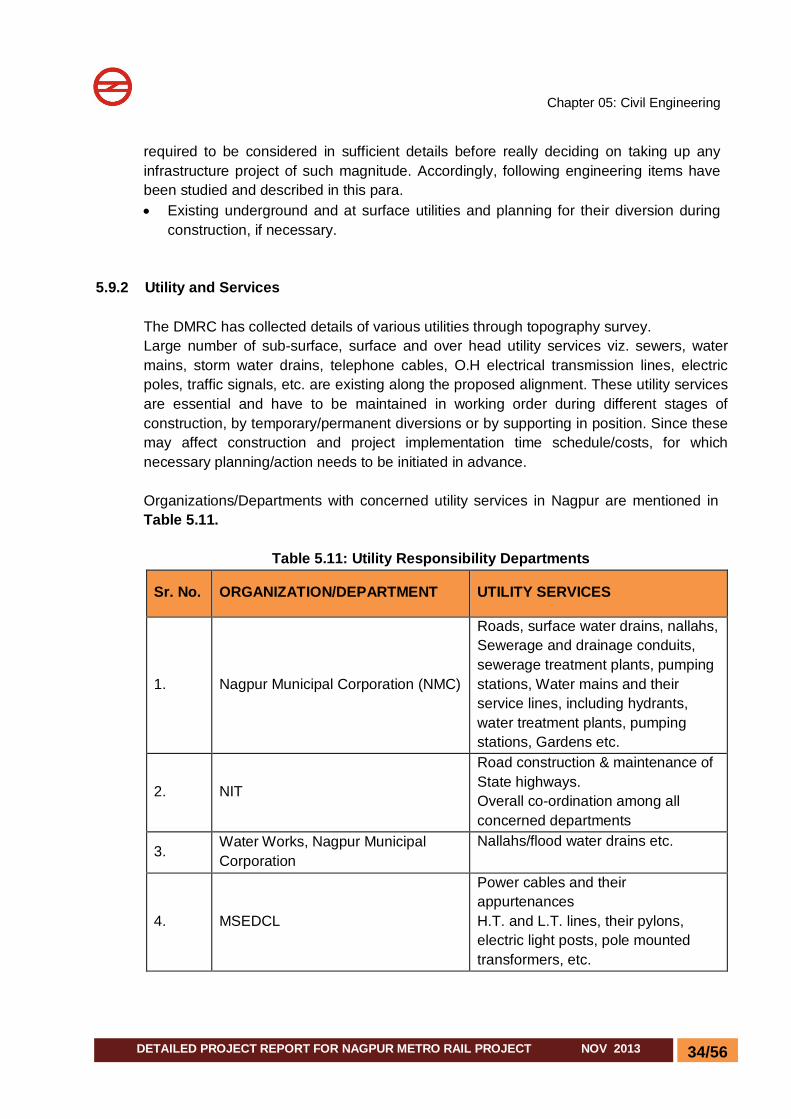
5.9.2 Utility and Services
The DMRC has collected details of various utilities through topography survey. Large number of sub-surface, surface and over head utility services viz. sewers, water mains, storm water drains, telephone cables, O.H electrical transmission lines, electric poles, traffic signals, etc. are existing along the proposed alignment. These utility services are essential and have to be maintained in working order during different stages of construction, by temporary/permanent diversions or by supporting in position. Since these may affect construction and project implementation time schedule/costs, for which necessary planning/action needs to be initiated in advance. Organizations/Departments with concerned utility services in Nagpur are mentioned in Table 5.11.
Table 5.11: Utility Responsibility Departments
Sr. No. ORGANIZATION/DEPARTMENT UTILITY SERVICES
1. Nagpur Municipal Corporation (NMC)
Roads, surface water drains, nallahs, Sewerage and drainage conduits, sewerage treatment plants, pumping stations, Water mains and their service lines, including hydrants, water treatment plants, pumping stations, Gardens etc.
2. NIT
Road construction & maintenance of State highways. Overall co-ordination among all concerned departments
3. Water Works, Nagpur Municipal Corporation
Nallahs/flood water drains etc.
4. MSEDCL
Power cables and their appurtenances H.T. and L.T. lines, their pylons, electric light posts, pole mounted transformers, etc.

Chapter 05: Civil Engineering
35/56 DETAILED PROJECT REPORT FOR NAGPUR METRO RAIL PROJECT NOV 2013
Sr. No. ORGANIZATION/DEPARTMENT UTILITY SERVICES
5. Bharat Sanchar Nigam Ltd. (BSNL) Telecommunication cables, junction boxes, telephone posts, O.H. lines, etc.
6. Nagpur Traffic Police Traffic signal posts, junction boxes and cable connections, etc.
Assessment of the type and location of underground utilities running along and across the proposed route alignment at Nagpur will be undertaken with the help of data available with concerned authorities, who generally maintain plans and data of such utility services. Particulars of main utilities i.e. trunk and main sewers/drainage conduits, water mains, OH & UG Electric cable, Telecom cable etc. have been marked on alignment plans.
5.9.3 Diversion of Underground Utilities
While planning for diversion of underground utility services viz. sewer lines, water pipelines, cables, etc., during construction of MRTS alignment, following guidelines have been adopted:
Utility services have to be kept operational during the entire construction period and after completion of project. All proposals should therefore, ensure their uninterrupted functioning.
Sewer lines and water supply lines are mainly affected in underground cut and cover construction. These services are proposed to be maintained by temporarily replacing them with CI/Steel pipelines and supporting them during construction, these will be encased in reinforced cement concrete after completion of construction and retained as permanent lines
Where permanent diversion of the affected utility is not found feasible, temporary diversion with CI/Steel pipes without manholes is proposed during construction. After completion of construction, these will be replaced with conventional pipes and manholes.
The elevated viaduct does not pose much of a difficulty in negotiating the underground utility services, especially those running across the alignment. The utilities infringing at pier location can be easily diverted away from the pile cap location.
In case a major utility is running along/across the alignment which cannot be diverted or the diversion of which is difficult, time consuming and uneconomical, the spanning arrangement of the viaduct and layout of piles in the foundation may be suitably adjusted to ensure that no foundation needs be constructed at the location, where utility is crossing the proposed alignment. The utility service can also be encased within the foundation piles.
Chapter 05: Civil Engineering
36/56 DETAILED PROJECT REPORT FOR NAGPUR METRO RAIL PROJECT NOV 2013
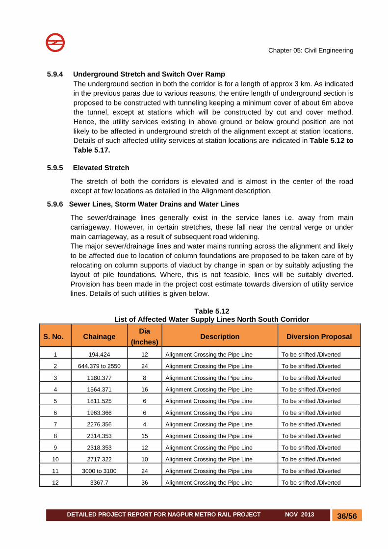
5.9.4 Underground Stretch and Switch Over Ramp The underground section in both the corridor is for a length of approx 3 km. As indicated in the previous paras due to various reasons, the entire length of underground section is proposed to be constructed with tunneling keeping a minimum cover of about 6m above the tunnel, except at stations which will be constructed by cut and cover method. Hence, the utility services existing in above ground or below ground position are not likely to be affected in underground stretch of the alignment except at station locations. Details of such affected utility services at station locations are indicated in Table 5.12 to Table 5.17.
5.9.5 Elevated Stretch
The stretch of both the corridors is elevated and is almost in the center of the road except at few locations as detailed in the Alignment description.
5.9.6 Sewer Lines, Storm Water Drains and Water Lines
The sewer/drainage lines generally exist in the service lanes i.e. away from main carriageway. However, in certain stretches, these fall near the central verge or under main carriageway, as a result of subsequent road widening. The major sewer/drainage lines and water mains running across the alignment and likely to be affected due to location of column foundations are proposed to be taken care of by relocating on column supports of viaduct by change in span or by suitably adjusting the layout of pile foundations. Where, this is not feasible, lines will be suitably diverted. Provision has been made in the project cost estimate towards diversion of utility service lines. Details of such utilities is given below.
Table 5.12
List of Affected Water Supply Lines North South Corridor
S. No. Chainage Dia
(Inches) Description Diversion Proposal
1 194.424 12 Alignment Crossing the Pipe Line To be shifted /Diverted
2 644.379 to 2550 24 Alignment Crossing the Pipe Line To be shifted /Diverted
3 1180.377 8 Alignment Crossing the Pipe Line To be shifted /Diverted
4 1564.371 16 Alignment Crossing the Pipe Line To be shifted /Diverted
5 1811.525 6 Alignment Crossing the Pipe Line To be shifted /Diverted
6 1963.366 6 Alignment Crossing the Pipe Line To be shifted /Diverted
7 2276.356 4 Alignment Crossing the Pipe Line To be shifted /Diverted
8 2314.353 15 Alignment Crossing the Pipe Line To be shifted /Diverted
9 2318.353 12 Alignment Crossing the Pipe Line To be shifted /Diverted
10 2717.322 10 Alignment Crossing the Pipe Line To be shifted /Diverted
11 3000 to 3100 24 Alignment Crossing the Pipe Line To be shifted /Diverted
12 3367.7 36 Alignment Crossing the Pipe Line To be shifted /Diverted
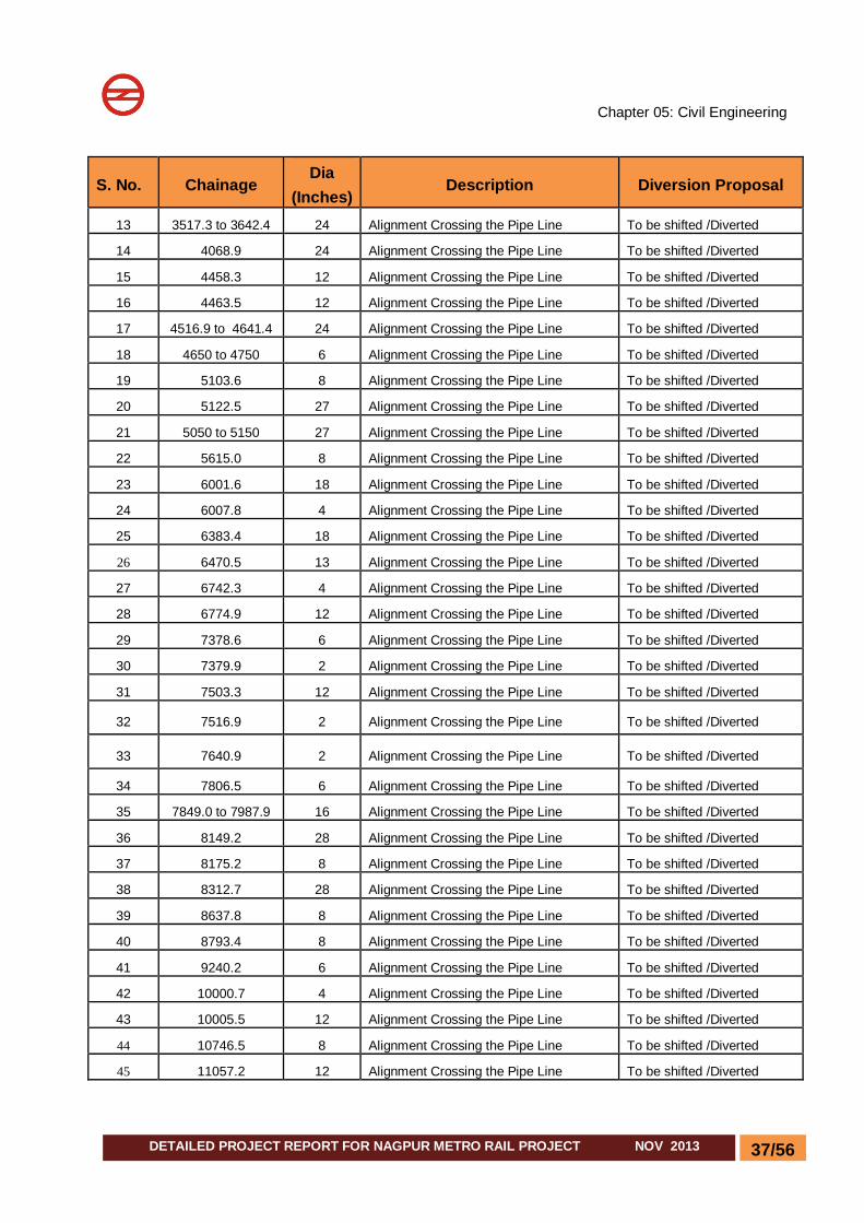
Chapter 05: Civil Engineering
37/56 DETAILED PROJECT REPORT FOR NAGPUR METRO RAIL PROJECT NOV 2013
S. No. Chainage Dia
(Inches) Description Diversion Proposal
13 3517.3 to 3642.4 24 Alignment Crossing the Pipe Line To be shifted /Diverted
14 4068.9 24 Alignment Crossing the Pipe Line To be shifted /Diverted
15 4458.3 12 Alignment Crossing the Pipe Line To be shifted /Diverted
16 4463.5 12 Alignment Crossing the Pipe Line To be shifted /Diverted
17 4516.9 to 4641.4 24 Alignment Crossing the Pipe Line To be shifted /Diverted
18 4650 to 4750 6 Alignment Crossing the Pipe Line To be shifted /Diverted
19 5103.6 8 Alignment Crossing the Pipe Line To be shifted /Diverted
20 5122.5 27 Alignment Crossing the Pipe Line To be shifted /Diverted
21 5050 to 5150 27 Alignment Crossing the Pipe Line To be shifted /Diverted
22 5615.0 8 Alignment Crossing the Pipe Line To be shifted /Diverted
23 6001.6 18 Alignment Crossing the Pipe Line To be shifted /Diverted
24 6007.8 4 Alignment Crossing the Pipe Line To be shifted /Diverted
25 6383.4 18 Alignment Crossing the Pipe Line To be shifted /Diverted
26 6470.5 13 Alignment Crossing the Pipe Line To be shifted /Diverted
27 6742.3 4 Alignment Crossing the Pipe Line To be shifted /Diverted
28 6774.9 12 Alignment Crossing the Pipe Line To be shifted /Diverted
29 7378.6 6 Alignment Crossing the Pipe Line To be shifted /Diverted
30 7379.9 2 Alignment Crossing the Pipe Line To be shifted /Diverted
31 7503.3 12 Alignment Crossing the Pipe Line To be shifted /Diverted
32 7516.9 2 Alignment Crossing the Pipe Line To be shifted /Diverted
33 7640.9 2 Alignment Crossing the Pipe Line To be shifted /Diverted
34 7806.5 6 Alignment Crossing the Pipe Line To be shifted /Diverted
35 7849.0 to 7987.9 16 Alignment Crossing the Pipe Line To be shifted /Diverted
36 8149.2 28 Alignment Crossing the Pipe Line To be shifted /Diverted
37 8175.2 8 Alignment Crossing the Pipe Line To be shifted /Diverted
38 8312.7 28 Alignment Crossing the Pipe Line To be shifted /Diverted
39 8637.8 8 Alignment Crossing the Pipe Line To be shifted /Diverted
40 8793.4 8 Alignment Crossing the Pipe Line To be shifted /Diverted
41 9240.2 6 Alignment Crossing the Pipe Line To be shifted /Diverted
42 10000.7 4 Alignment Crossing the Pipe Line To be shifted /Diverted
43 10005.5 12 Alignment Crossing the Pipe Line To be shifted /Diverted
44 10746.5 8 Alignment Crossing the Pipe Line To be shifted /Diverted
45 11057.2 12 Alignment Crossing the Pipe Line To be shifted /Diverted

Chapter 05: Civil Engineering
38/56 DETAILED PROJECT REPORT FOR NAGPUR METRO RAIL PROJECT NOV 2013
S. No. Chainage Dia
(Inches) Description Diversion Proposal
46 11087.2 24 Alignment Crossing the Pipe Line To be shifted /Diverted
47 11127.8 10 Alignment Crossing the Pipe Line To be shifted /Diverted
48 11424.8 27 Alignment Crossing the Pipe Line To be shifted /Diverted
49 11584.0 27 Alignment Crossing the Pipe Line To be shifted /Diverted
50 11659.5 12 Alignment Crossing the Pipe Line To be shifted /Diverted
51 11720.8 4 Alignment Crossing the Pipe Line To be shifted /Diverted
52 11895.6 14 Alignment Crossing the Pipe Line To be shifted /Diverted
53 12068.2 4 Alignment Crossing the Pipe Line To be shifted /Diverted
54 12129.4 4 Alignment Crossing the Pipe Line To be shifted /Diverted
55 12214.4 14 Alignment Crossing the Pipe Line To be shifted /Diverted
56 12294.1 10 Alignment Crossing the Pipe Line To be shifted /Diverted
57 12322.7 to
12334.6 10 Alignment Crossing the Pipe Line To be shifted /Diverted
58 13999.5 6 Alignment Crossing the Pipe Line To be shifted /Diverted
Table 5.13 List of Affected Water Supply Lines on East West Corridor
S.No. Chainage Dia
(Inches) Description Diversion Proposal
1 220.1 8 Alignment Crossing the Pipe Line To be shifted /Diverted
2 258.1 28 Alignment Crossing the Pipe Line To be shifted /Diverted
3 435.0 8 Alignment Crossing the Pipe Line To be shifted /Diverted
4 851.9 8 Alignment Crossing the Pipe Line To be shifted /Diverted
5 1086.5 36 Alignment Crossing the Pipe Line To be shifted /Diverted
6 1067.7 4 Alignment Crossing the Pipe Line To be shifted /Diverted
7 1102.1 4 Alignment Crossing the Pipe Line To be shifted /Diverted
8 1170.5 6 Alignment Crossing the Pipe Line To be shifted /Diverted
9 1456.5 12 Alignment Crossing the Pipe Line To be shifted /Diverted
10 1486.9 8 Alignment Crossing the Pipe Line To be shifted /Diverted
11 2463.6 12 Alignment Crossing the Pipe Line To be shifted /Diverted
12 2672.0 24 Alignment Crossing the Pipe Line To be shifted /Diverted
13 2965.4 36 Alignment Crossing the Pipe Line To be shifted /Diverted
14 2968.8 12 Alignment Crossing the Pipe Line To be shifted /Diverted
15 3520.7 16 Alignment Crossing the Pipe Line To be shifted /Diverted

Chapter 05: Civil Engineering
39/56 DETAILED PROJECT REPORT FOR NAGPUR METRO RAIL PROJECT NOV 2013
S.No. Chainage Dia (Inches)
Description Diversion Proposal
16 3532.0 15 Alignment Crossing the Pipe Line To be shifted /Diverted
17 3563.7 6 Alignment Crossing the Pipe Line To be shifted /Diverted
18 3782.1 6 Alignment Crossing the Pipe Line To be shifted /Diverted
19 4059.9 6 Alignment Crossing the Pipe Line To be shifted /Diverted
20 4090.1 18 Alignment Crossing the Pipe Line To be shifted /Diverted
21 4091.8 6 Alignment Crossing the Pipe Line To be shifted /Diverted
22 4173.7 4 Alignment Crossing the Pipe Line To be shifted /Diverted
23 4187.5 8 Alignment Crossing the Pipe Line To be shifted /Diverted
24 4491.5 4 Alignment Crossing the Pipe Line To be shifted /Diverted
25 4662.9 12 Alignment Crossing the Pipe Line To be shifted /Diverted
26 4926.6 4 Alignment Crossing the Pipe Line To be shifted /Diverted
27 5005.8 24 Alignment Crossing the Pipe Line To be shifted /Diverted
28 5021.4 6 Alignment Crossing the Pipe Line To be shifted /Diverted
29 5491.1 12 Alignment Crossing the Pipe Line To be shifted /Diverted
30 5501.0 10 Alignment Crossing the Pipe Line To be shifted /Diverted
31 5706.4 7 Alignment Crossing the Pipe Line To be shifted /Diverted
32 5793.7 to 5878.2 24 Alignment Crossing the Pipe Line To be shifted /Diverted
33 5980.1 15 Alignment Crossing the Pipe Line To be shifted /Diverted
34 6087.6 6 Alignment Crossing the Pipe Line To be shifted /Diverted
35 6885.3 18 Alignment Crossing the Pipe Line To be shifted /Diverted
36 6886.5 8 Alignment Crossing the Pipe Line To be shifted /Diverted
37 6902.9 to 6906.6 13,12 & 6 Alignment Crossing the Pipe Line To be shifted /Diverted
38 6934.5 to 6964.1 4 Alignment Crossing the Pipe Line To be shifted /Diverted
39 7033.8 4 Alignment Crossing the Pipe Line To be shifted /Diverted
40 7095.6 4 Alignment Crossing the Pipe Line To be shifted /Diverted
41 7279.5 to 7284.1 12 & 6 Alignment Crossing the Pipe Line To be shifted /Diverted
42 7711.2 4 Alignment Crossing the Pipe Line To be shifted /Diverted
43 7783.3 6 Alignment Crossing the Pipe Line To be shifted /Diverted
44 7100 to 7150 12 & 13 Alignment Crossing the Pipe Line To be shifted /Diverted
45 8764.2 3 Alignment Crossing the Pipe Line To be shifted /Diverted
46 9264.8 6 Alignment Crossing the Pipe Line To be shifted /Diverted
47 9585.5 6 Alignment Crossing the Pipe Line To be shifted /Diverted
48 10172.8 9 Alignment Crossing the Pipe Line To be shifted /Diverted
49 10759.8 to 10764.3 24 & 28 Alignment Crossing the Pipe Line To be shifted /Diverted
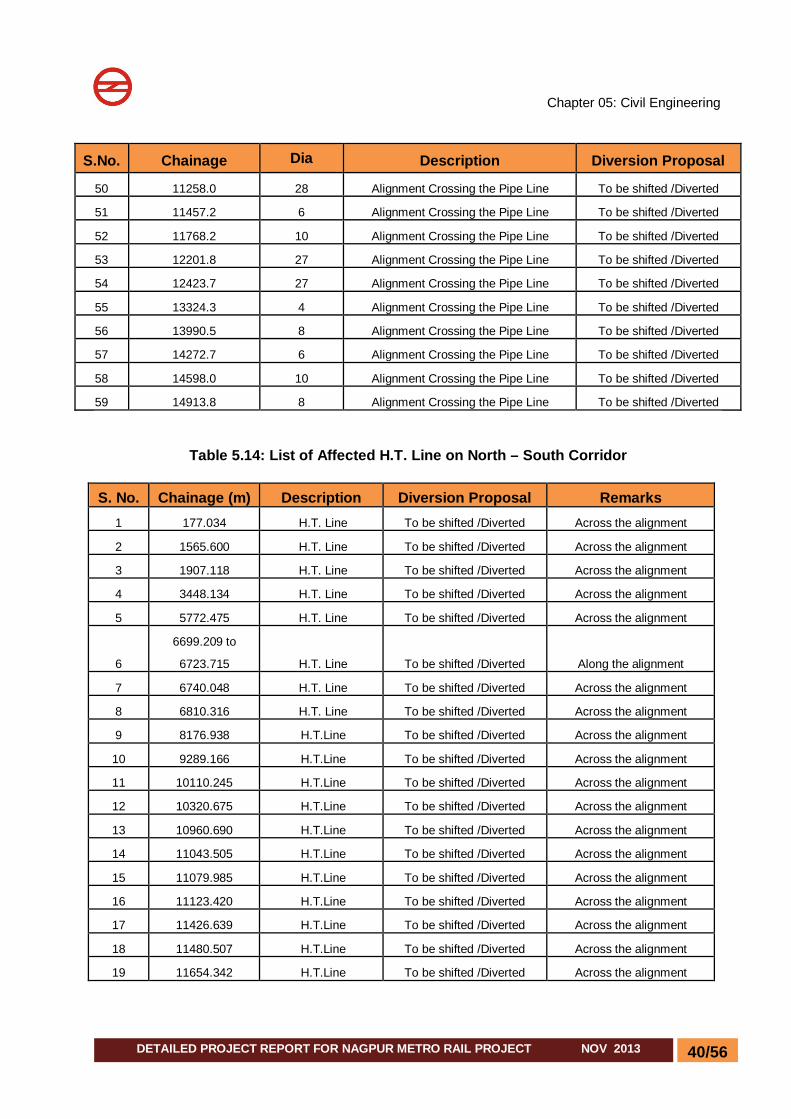
Chapter 05: Civil Engineering
40/56 DETAILED PROJECT REPORT FOR NAGPUR METRO RAIL PROJECT NOV 2013
S.No. Chainage Dia (Inches)
Description Diversion Proposal
50 11258.0 28 Alignment Crossing the Pipe Line To be shifted /Diverted
51 11457.2 6 Alignment Crossing the Pipe Line To be shifted /Diverted
52 11768.2 10 Alignment Crossing the Pipe Line To be shifted /Diverted
53 12201.8 27 Alignment Crossing the Pipe Line To be shifted /Diverted
54 12423.7 27 Alignment Crossing the Pipe Line To be shifted /Diverted
55 13324.3 4 Alignment Crossing the Pipe Line To be shifted /Diverted
56 13990.5 8 Alignment Crossing the Pipe Line To be shifted /Diverted
57 14272.7 6 Alignment Crossing the Pipe Line To be shifted /Diverted
58 14598.0 10 Alignment Crossing the Pipe Line To be shifted /Diverted
59 14913.8 8 Alignment Crossing the Pipe Line To be shifted /Diverted
Table 5.14: List of Affected H.T. Line on North – South Corridor
S. No. Chainage (m) Description Diversion Proposal Remarks 1 177.034 H.T. Line To be shifted /Diverted Across the alignment
2 1565.600 H.T. Line To be shifted /Diverted Across the alignment
3 1907.118 H.T. Line To be shifted /Diverted Across the alignment
4 3448.134 H.T. Line To be shifted /Diverted Across the alignment
5 5772.475 H.T. Line To be shifted /Diverted Across the alignment
6
6699.209 to
6723.715 H.T. Line To be shifted /Diverted Along the alignment
7 6740.048 H.T. Line To be shifted /Diverted Across the alignment
8 6810.316 H.T. Line To be shifted /Diverted Across the alignment
9 8176.938 H.T.Line To be shifted /Diverted Across the alignment
10 9289.166 H.T.Line To be shifted /Diverted Across the alignment
11 10110.245 H.T.Line To be shifted /Diverted Across the alignment
12 10320.675 H.T.Line To be shifted /Diverted Across the alignment
13 10960.690 H.T.Line To be shifted /Diverted Across the alignment
14 11043.505 H.T.Line To be shifted /Diverted Across the alignment
15 11079.985 H.T.Line To be shifted /Diverted Across the alignment
16 11123.420 H.T.Line To be shifted /Diverted Across the alignment
17 11426.639 H.T.Line To be shifted /Diverted Across the alignment
18 11480.507 H.T.Line To be shifted /Diverted Across the alignment
19 11654.342 H.T.Line To be shifted /Diverted Across the alignment

Chapter 05: Civil Engineering
41/56 DETAILED PROJECT REPORT FOR NAGPUR METRO RAIL PROJECT NOV 2013
S. No. Chainage (m) Description Diversion Proposal Remarks 20 11795.474 H.T.Line To be shifted /Diverted Across the alignment
21 11863.563 H.T.Line To be shifted /Diverted Across the alignment
22 12107.901 H.T.Line To be shifted /Diverted Across the alignment
23 12228.040 H.T.Line To be shifted /Diverted Across the alignment
24 12293.667 H.T.Line To be shifted /Diverted Across the alignment
25 12342.128 H.T.Line To be shifted /Diverted Across the alignment
26 20563.075 H.T.Line To be shifted /Diverted Across the alignment
Table 5.15: List of Affected H.T. Poles on North – South Corridor
S. No. Chainage (m) Description Nos. Remarks 1 6712.088 HT Line pole 1 To be shifted /Diverted
2 6714.648 HT Line pole 1 To be shifted /Diverted
3 6720.222 HT Line pole 1 To be shifted /Diverted
4 6723.267 HT Line pole 1 To be shifted /Diverted
5 6799.051 HT Line pole 1 To be shifted /Diverted
6 8346.091 HT Line pole 1 To be shifted /Diverted
7 12107.142 HT Line pole 2 To be shifted /Diverted
8 12328.163 HT Line pole 1 To be shifted /Diverted
TOTAL 9
Table 5.16: List of Affected H.T. Line East West Corridor
S.No. Chainage (m) Description Diversion Proposal Remarks
1
5794.174 to
5885.633 H.T.Line To be shifted /Diverted Along the alignment
2 6098.419 H.T.Line To be shifted /Diverted Across the alignment
3 6116.585 H.T.Line To be shifted /Diverted Across the alignment
4 6449.289 H.T.Line To be shifted /Diverted Across the alignment
5 6807.847 H.T.Line To be shifted /Diverted Across the alignment
6 6931.295 H.T.Line To be shifted /Diverted Across the alignment
7 6936.945 H.T.Line To be shifted /Diverted Across the alignment
8 6975.686 H.T.Line To be shifted /Diverted Across the alignment
9 7281.061 H.T.Line To be shifted /Diverted Across the alignment

Chapter 05: Civil Engineering
42/56 DETAILED PROJECT REPORT FOR NAGPUR METRO RAIL PROJECT NOV 2013
S.No. Chainage (m) Description Diversion Proposal Remarks 10 7295.523 H.T.Line To be shifted /Diverted Across the alignment
11 7547.827 H.T.Line To be shifted /Diverted Across the alignment
12 7591.701 H.T.Line To be shifted /Diverted Across the alignment
13 7707.968 H.T.Line To be shifted /Diverted Across the alignment
14 7768.575 H.T.Line To be shifted /Diverted Across the alignment
15 7814.073 H.T.Line To be shifted /Diverted Across the alignment
16 10126.058 H.T.Line To be shifted /Diverted Across the alignment
17 11151.141 H.T.Line To be shifted /Diverted Across the alignment
18 12165.311 H.T.Line To be shifted /Diverted Across the alignment
19 13970.942 H.T.Line To be shifted /Diverted Across the alignment
20 15318.343 H.T.Line To be shifted /Diverted Across the alignment
21 15820.202 H.T.Line To be shifted /Diverted Across the alignment
22 16206.946 H.T.Line To be shifted /Diverted Across the alignment
23 16574.747 H.T.Line To be shifted /Diverted Across the alignment
24 16929.842 H.T.Line To be shifted /Diverted Across the alignment
Table 5.17: List of Affected H.T. Line Poles East West Corridor
S.No. Chainage (m) Description NOs. Remarks 1 5794.174 HT Line Pole 1 To be shifted /Diverted
2 5826.677 HT Line Pole 1 To be shifted /Diverted
3 6100.885 HT Line Pole 1 To be shifted /Diverted
4 6980.015 HT Line Pole 1 To be shifted /Diverted
5 7285.225 HT Line Pole 1 To be shifted /Diverted
6 11561.204 HT Line Pole 3 To be shifted /Diverted
7 11726.849 HT Line Pole 4 To be shifted /Diverted
TOTAL 12 To be shifted /Diverted Apart from this some other ground utilities, interfering with the proposed alignments,
namely street light poles, traffic signal posts, telecommunication posts, junction boxes, etc. are also required to be shifted and relocated suitably during construction of elevated viaduct.
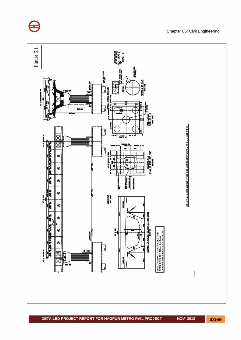
Chapter 05: Civil Engineering
43/56 DETAILED PROJECT REPORT FOR NAGPUR METRO RAIL PROJECT NOV 2013
Figu
re 5
.1

Chapter 05: Civil Engineering
44/56 DETAILED PROJECT REPORT FOR NAGPUR METRO RAIL PROJECT NOV 2013
Figure 5.2
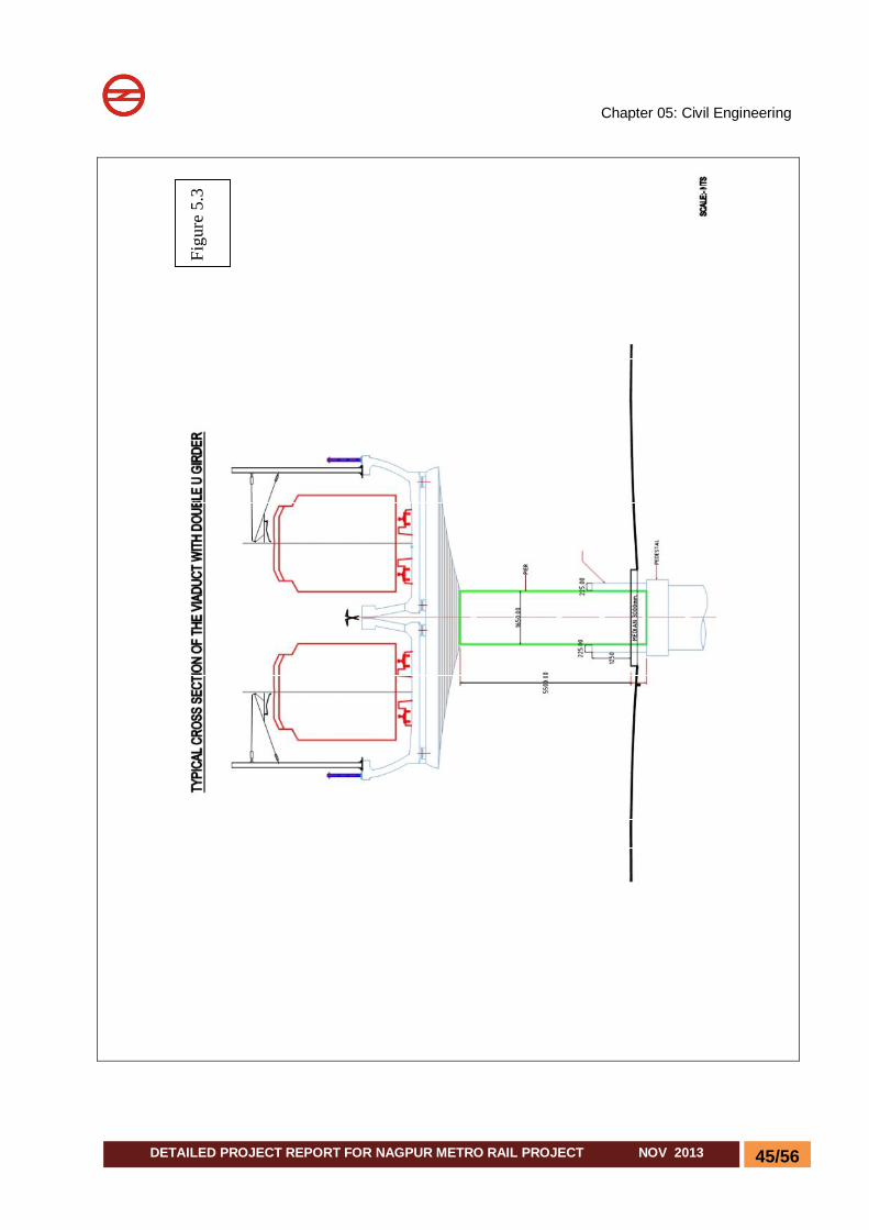
Chapter 05: Civil Engineering
45/56 DETAILED PROJECT REPORT FOR NAGPUR METRO RAIL PROJECT NOV 2013
Figu
re 5
.3

Chapter 05: Civil Engineering
46/56 DETAILED PROJECT REPORT FOR NAGPUR METRO RAIL PROJECT NOV 2013
Figu
re 5
.4
NAG
PUR
MET
RO
RAI
L PR
OJE
CT

Chapter 05: Civil Engineering
47/56 DETAILED PROJECT REPORT FOR NAGPUR METRO RAIL PROJECT NOV 2013
Figu
re 5
.5
NAG
PUR
MET
RO
RAI
L PR
OJE
CT
NAG
PUR
MET
RO
RAI
L PR
OJE
CT
NAG
PUR
MET
RO
RAI
L PR
OJE
CT
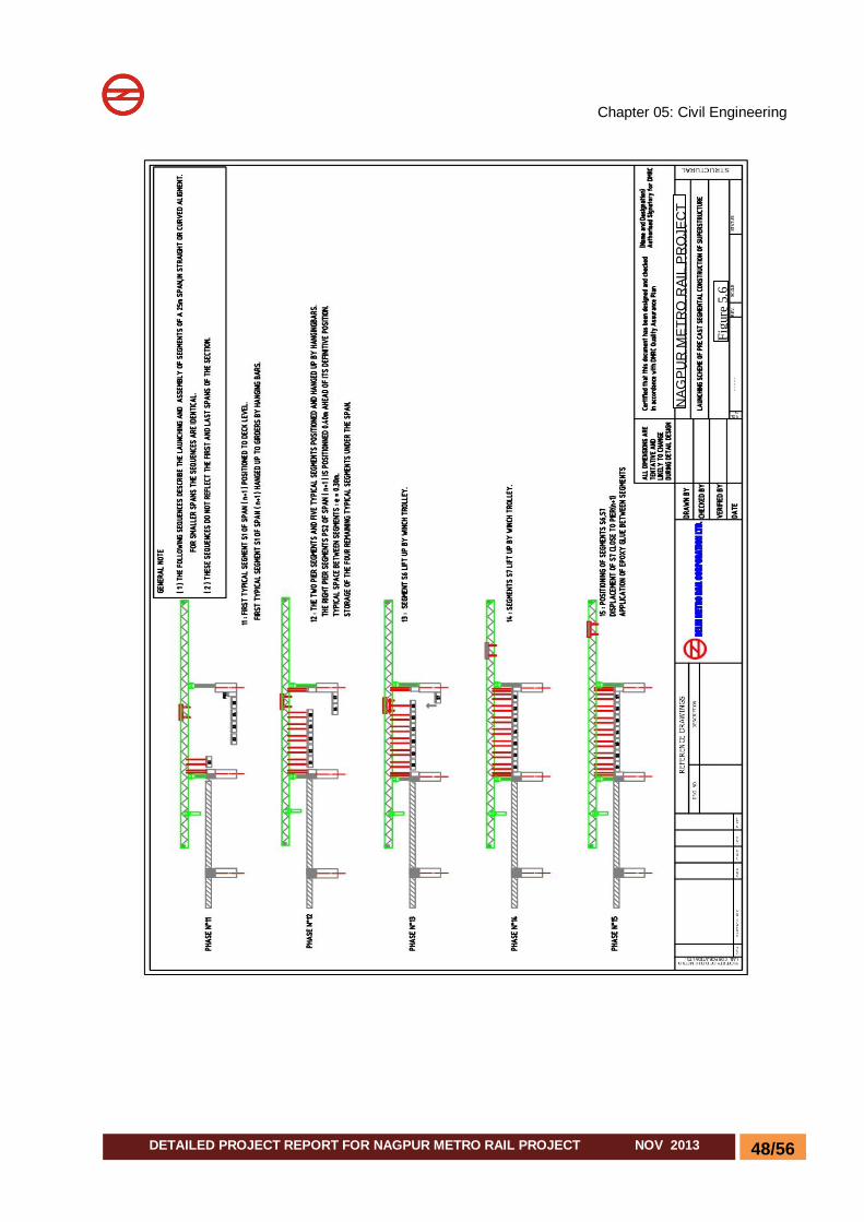
Chapter 05: Civil Engineering
48/56 DETAILED PROJECT REPORT FOR NAGPUR METRO RAIL PROJECT NOV 2013
Figu
re 5
.6
NAG
PUR
MET
RO
RAI
L PR
OJE
CT

Chapter 05: Civil Engineering
49/56 DETAILED PROJECT REPORT FOR NAGPUR METRO RAIL PROJECT NOV 2013
Figu
re 5
.7
NAG
PUR
MET
RO
RAI
L PR
OJE
CT

Chapter 05: Civil Engineering
50/56 DETAILED PROJECT REPORT FOR NAGPUR METRO RAIL PROJECT NOV 2013
Figu
re 5
.8
NA
GPU
R M
ETR
O R
AIL
PR
OJE
CT

Chapter 05: Civil Engineering
51/56 DETAILED PROJECT REPORT FOR NAGPUR METRO RAIL PROJECT NOV 2013
Figu
re 5
.9

Chapter 05: Civil Engineering
52/56 DETAILED PROJECT REPORT FOR NAGPUR METRO RAIL PROJECT NOV 2013
Figu
re 5
.10

Chapter 05: Civil Engineering
53/56 DETAILED PROJECT REPORT FOR NAGPUR METRO RAIL PROJECT NOV 2013
Figu
re 5
.11
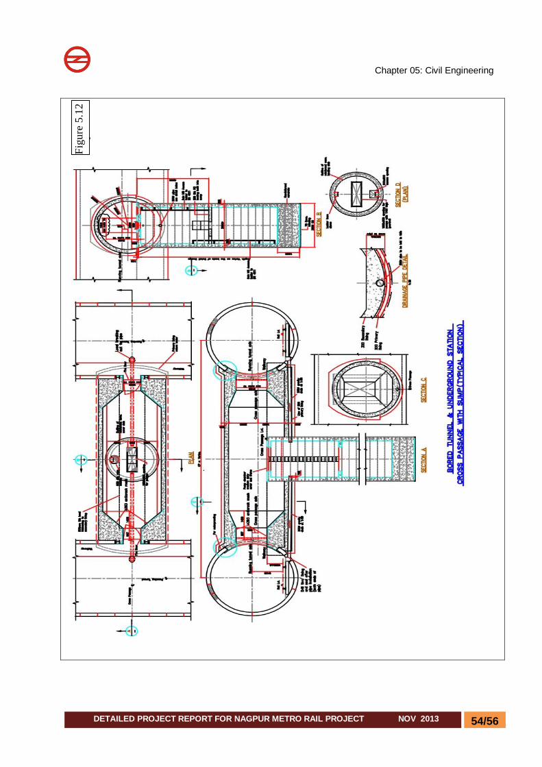
Chapter 05: Civil Engineering
54/56 DETAILED PROJECT REPORT FOR NAGPUR METRO RAIL PROJECT NOV 2013
Figu
re 5
.12
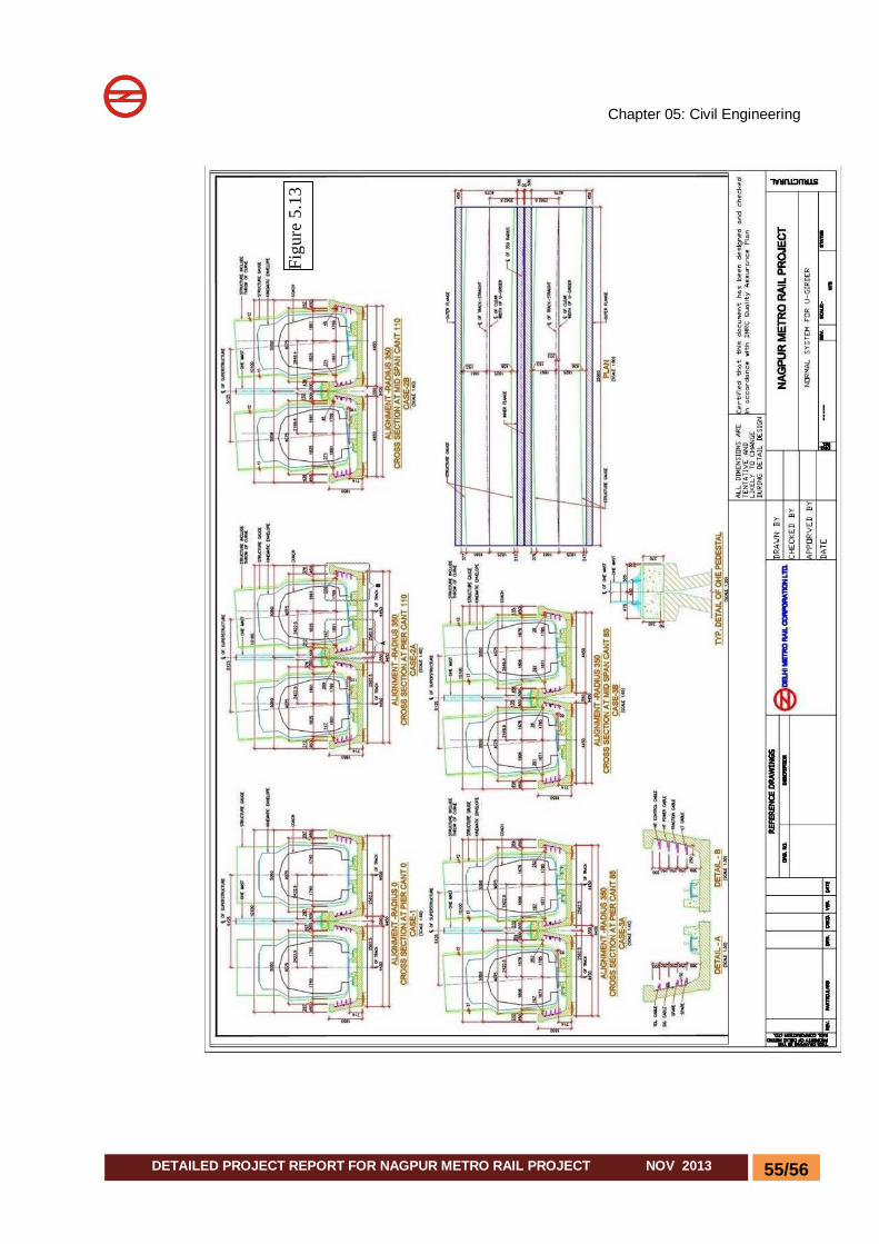
Chapter 05: Civil Engineering
55/56 DETAILED PROJECT REPORT FOR NAGPUR METRO RAIL PROJECT NOV 2013
Figu
re 5
.13
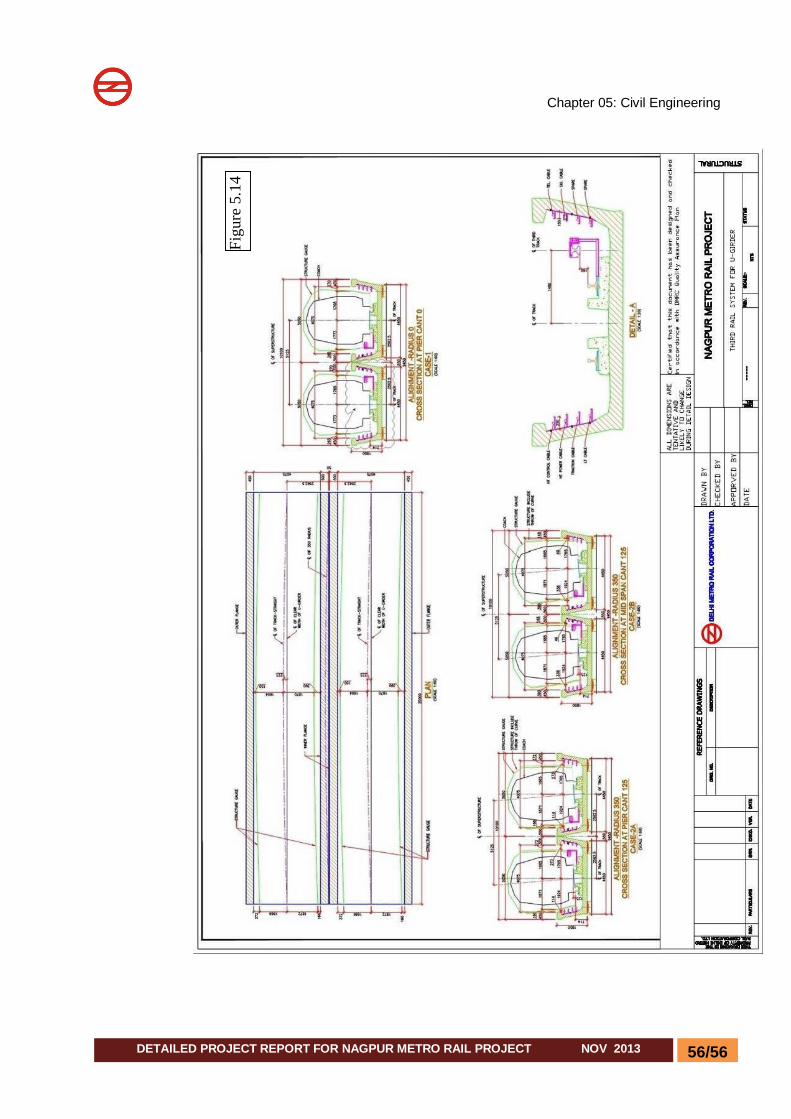
Chapter 05: Civil Engineering
56/56 DETAILED PROJECT REPORT FOR NAGPUR METRO RAIL PROJECT NOV 2013
Figu
re 5
.14