center winding versus surface … a center winder with no nip roller the wot is either equal or less...
TRANSCRIPT

15th Fundamental Research Symposium, Cambridge, September 2013 403
CENTER WINDING VERSUS SURFACE WINDING: THE EFFECT OF WINDER
TYPE AND WEB MATERIAL PROPERTIES ON WOUND ROLL
STRESSES
Yao Ren, Balaji Kandadai1, and James K. GoodMechanical & Aerospace Engineering
Oklahoma State UniversityStillwater, OK, USA
ABSTRACT
The choice of winder type for various web materials has long been a qualitative discussion. Web materials are vast and hence the range of web material properties is also vast. Valid but con icting opinions for an optimal winder type have been developed from experience bases that represent this vast range of web materials. The purpose of this publication is to quantify how the internal stresses in wound rolls are affected by winder type and web material properties.
INTRODUCTION
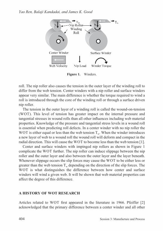
Schematic diagrams of center and surface winders are shown in Figure 1. Center winders without an impinged nip roller will certainly function at low winding speeds. Most practical center and all surface winders employ a nip roller. The nip roller will allow high speed winding by excluding entrained air into the wound
1 now with Kimberly Clark Corporation, USA
25770.indb 403 15/08/2013 08:11
Preferred citation: Y. Ren, B. Kandadai and J.K. Good. Center winding versus surface winding: the effect of winder type and web material properties on wound roll stresses. In Advances in Pulp and Paper Research, Cambridge 2013, Trans. of the XVth Fund. Res. Symp. Cambridge, 2013, (S.J. I’Anson, ed.), pp 403–447, FRC, Manchester, 2018. DOI: 10.15376/frc.2013.1.403.
Yao Ren, Balaji Kandadai, and James K. Good
404 Session 3: Manufacture and Process
roll. The nip roller also causes the tension in the outer layer of the winding roll to differ from the web tension. Center winders with a nip roller and surface winders appear very similar. The main difference is whether the torque required to wind a roll is introduced through the core of the winding roll or through a surface driven nip roller.
The tension in the outer layer of a winding roll is called the wound- on- tension (WOT). This level of tension has greater impact on the internal pressure and tangential stresses in wound rolls than all other in uences including web material properties. Knowledge of the pressure and tangential stress levels in a wound roll is essential when predicting roll defects. In a center winder with no nip roller the WOT is either equal or less than the web tension Tw. When the winder introduces a new layer of web to a wound roll the wound roll will deform and compact in the radial direction. This will cause the WOT to become less than the web tension [1].
Center and surface winders with impinged nip rollers as shown in Figure 1 complicate the WOT further. The nip roller can induce slippage between the nip roller and the outer layer and also between the outer layer and the layer beneath. Whenever slippage occurs the slip forces may cause the WOT to be either less or greater than the web tension Tw depending on the direction of the slip forces. The WOT is what distinguishes the difference between how center and surface winders will wind a given web. It will be shown that web material properties can affect the degree of this difference.
A HISTORY OF WOT RESEARCH
Articles related to WOT rst appeared in the literature in 1966. Pfeiffer [2] acknowledged that the primary difference between a center winder and all other
Figure 1. Winders.
25770.indb 404 15/08/2013 08:11 25770.indb 405 15/08/2013 08:11
25770.indb 404 15/08/2013 08:11
Center Winding Versus Surface Winding
15th Fundamental Research Symposium, Cambridge, September 2013 405
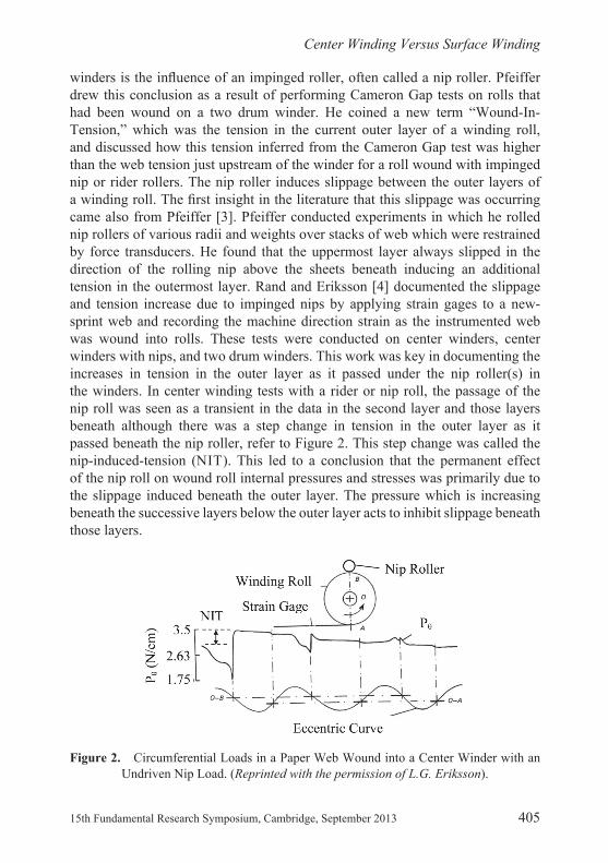
winders is the in uence of an impinged roller, often called a nip roller. Pfeiffer drew this conclusion as a result of performing Cameron Gap tests on rolls that had been wound on a two drum winder. He coined a new term “Wound- In- Tension,” which was the tension in the current outer layer of a winding roll, and discussed how this tension inferred from the Cameron Gap test was higher than the web tension just upstream of the winder for a roll wound with impinged nip or rider rollers. The nip roller induces slippage between the outer layers of a winding roll. The rst insight in the literature that this slippage was occurring came also from Pfeiffer [3]. Pfeiffer conducted experiments in which he rolled nip rollers of various radii and weights over stacks of web which were restrained by force transducers. He found that the uppermost layer always slipped in the direction of the rolling nip above the sheets beneath inducing an additional tension in the outermost layer. Rand and Eriksson [4] documented the slippage and tension increase due to impinged nips by applying strain gages to a new -sprint web and recording the machine direction strain as the instrumented web was wound into rolls. These tests were conducted on center winders, center winders with nips, and two drum winders. This work was key in documenting the increases in tension in the outer layer as it passed under the nip roller(s) in the winders. In center winding tests with a rider or nip roll, the passage of the nip roll was seen as a transient in the data in the second layer and those layers beneath although there was a step change in tension in the outer layer as it passed beneath the nip roller, refer to Figure 2. This step change was called the nip- induced- tension (NIT). This led to a conclusion that the permanent effect of the nip roll on wound roll internal pressures and stresses was primarily due to the slippage induced beneath the outer layer. The pressure which is increasing beneath the successive layers below the outer layer acts to inhibit slippage beneath those layers.
Figure 2. Circumferential Loads in a Paper Web Wound into a Center Winder with an Undriven Nip Load. (Reprinted with the permission of L.G. Eriksson).
25770.indb 405 15/08/2013 08:11

Yao Ren, Balaji Kandadai, and James K. Good
406 Session 3: Manufacture and Process
Pfeiffer developed a means of measuring the wound- in tension in the outer layer on a surface winder [5]. After the outer layer passed beneath the incoming nip roll it was pulled away from the surface of the winding roll, wrapped about an idler mounted upon force transducers, and was nally allowed to return to the surface of the winding roll. This was the rst convenient means of directly study- ing the tension in the outer layer of a roll wound in the presence of a nip. Wound- in- tension could be studied as a function of winder operating parameters including incoming web tension and nip load that could be varied during the test. Pfeiffer found that increased nip load and incoming web tension caused the wound- in- tension to increase, again direct evidence that the nip roller was key in regulating the amount of slip between the outer layer and the layer beneath. Although Pfeiffer’s apparatus was setup in a way in which web tension and nip load were not completely independent his ndings were still very important. Pfeiffer also developed a wound- off tension measurement that allowed study of the tension in the outer layer during unwinding [6]. Theoretically, if there were no hysteretic or viscoelastic losses, the wound- in and wound- off tension records would be iden-tical. Pfeiffer produced a wound- off tension plot for the same roll that he produced a wound- in tension plot in the earlier publication. The two plots were similar qualitatively but there were magnitude differences that were due to the loss terms and interdependence between wound- in tension and nip load during winding. The concept of the wound- off tension method was novel in that it provided a technique by which a roll could be wound on any winder under any winder operating param-eters but through unwinding the wound- in tension could be deduced. When the wound- in tension was coupled with a wound roll model the internal pressures and stresses of winding could be known.
Good and Fikes [7] studied the pressures in rolls which were center wound with a rider roller (an undriven or idling nip roller). In this study force sensitive resis-tors were used to document the pressures in the wound roll after winding was complete. Using a wound roll model in the style of Hakiel [8], the tension in the outer layer in the winding roll was iterated until the model produced pressures of like magnitude to the experimental results. At this point the wound- in tension coined by Pfeiffer was re- coined as the Wound- On- Tension or WOT. The chief nding in this study was that the WOT was directly affected by web tension prior
to the winder and affected through a constant of proportionality to the nip load. The constant appeared to be similar in magnitude to the kinetic coef cient of fric-tion and thus the rst WOT algorithm for center winding with an undriven nip roller was generated:
(1)
25770.indb 406 15/08/2013 08:11 25770.indb 407 15/08/2013 08:11
25770.indb 406 15/08/2013 08:11
Center Winding Versus Surface Winding
15th Fundamental Research Symposium, Cambridge, September 2013 407
where the web tension (Tw) has units of stress or load per unit width (T), the nip load (N) has units of load per unit width of nip contact, and the web thickness (h) has units of length, thus the WOT can have units of stress or load per unit width. Expression (1) was used in place of the web tension as a boundary condition for Hakiel’s [8] winding model.
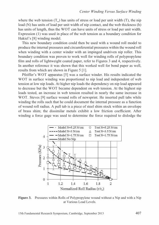
This new boundary condition could then be used with a wound roll model to produce the internal pressures and circumferential pressures within the wound roll when winding with a center winder with an impinged undriven nip roller. This boundary condition was proven to work well for winding rolls of polypropylene lm and rolls of lightweight coated paper, refer to Figures 3 and 4, respectively.
In another reference it was shown that this worked well for bond paper as well, results from which are shown in Figure 5 [1].
Pfeiffer’s WOT apparatus [5] was a surface winder. His results indicated the WOT in surface winding was proportional to nip load and independent of web tension at low nip loads. At higher nip loads the dependency on nip load appeared to decrease but the WOT became dependent on web tension. At the highest nip loads tested, an increase in web tension resulted in nearly the same increase in WOT. Steves [9] surface wound rolls of newsprint. He inserted pull tabs while winding the rolls such that he could document the internal pressure as a function of wound roll radius. A pull tab is a piece of steel shim stock within an envelope of brass shim; the dissimilar metals exhibit a low friction coef cient. After winding a force gage was used to determine the force required to dislodge the
Figure 3. Pressures within Rolls of Polypropylene wound without a Nip and with a Nip at Various Load Levels.
25770.indb 407 15/08/2013 08:11

Yao Ren, Balaji Kandadai, and James K. Good
408 Session 3: Manufacture and Process
Figure 4. Pressures within Rolls of Light Weight Coated Paper wound without a Nip and with a Nip at Various Load Levels.
Figure 5. Pressures within Rolls of Bond Paper wound with a Nip at Various Load Levels.
25770.indb 408 15/08/2013 08:11 25770.indb 409 15/08/2013 08:11
25770.indb 408 15/08/2013 08:11
Center Winding Versus Surface Winding
15th Fundamental Research Symposium, Cambridge, September 2013 409
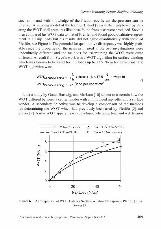
steel shim and with knowledge of the friction coef cient the pressure can be inferred. A winding model of the form of Hakiel [8] was then employed by iter-ating the WOT until pressures like those found from tests were produced. Steve’s then compared his WOT data to that of Pfeiffer and found good qualitative agree-ment at all nip loads but his results did not agree quantitatively with those of Pfeiffer, see Figure 6. The potential for quantitative discrepancy was highly prob-able since the properties of the news print used in the two investigations were undoubtedly different and the methods for ascertaining the WOT were quite different. A result from Steve’s work was a WOT algorithm for surface winding which was known to be valid for nip loads up to 17.5 N/cm for newsprint. The WOT algorithm was:
(2)
Later a study by Good, Hartwig, and Markum [10] set out to ascertain how the WOT differed between a center winder with an impinged nip roller and a surface winder. A secondary objective was to develop a comparison of the methods for determining the WOT which had previously been used by Pfeiffer [5] and Steves [9]. A new WOT apparatus was developed where nip load and web tension
Figure 6. A Comparison of WOT Data for Surface Winding Newsprint – Pfeiffer [5] vs. Steves [9].
25770.indb 409 15/08/2013 08:11

Yao Ren, Balaji Kandadai, and James K. Good
410 Session 3: Manufacture and Process
were truly independent winder operating input parameters. This was accom-plished by wrapping the nip roller with the web by radians and by maintaining the links which supported the nip roller in a vertical attitude. This was achieved by supporting the links on a position controlled sled upon linear ways as shown in Figure 7.
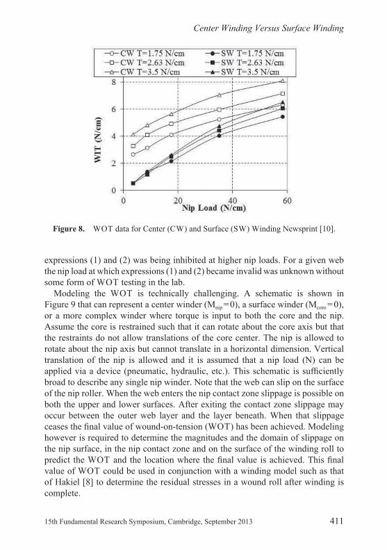
Measurements taken center and surface winding newsprint are shown in Figure 8 for three levels of winding tension. Consider the center winding results rst and note how the WOT curves differ by the difference in winding tension. It appears that each curve would intersect the coordinate axis at near the value of winding tension Tw associated with that test. The form of the WOT when nip load ranges from 0 to 20 N/cm is well described by expression (1). Also evident was that at high nip loads the WOT associated with center winding became less dependent on nip load. Note that when surface winding the WOT appeared unaffected by web tension Tw at low nip load levels and was well described by expression (2). The dependency of WOT on nip load decreased at higher nip load levels and developed some dependency on web tension. This behavior was noted as well in Figure 6 by Pfeiffer [5] and Steves [9].
This was the level of the state of the science in 1999. Based entirely on empirical evidence it was known that at lower nip loads the WOT behaved per expressions (1) and (2) for center and surface winders. There was evidence (see Figures 3, 4, 6 and 8) that the WOT fell below what was predicted by expres-sions (1) and (2) at higher nip loads. It appeared that the slip behavior given in
Figure 7. Schematic of Good et al [10] WOT apparatus.
25770.indb 410 15/08/2013 08:11 25770.indb 411 15/08/2013 08:11
25770.indb 410 15/08/2013 08:11
Center Winding Versus Surface Winding
15th Fundamental Research Symposium, Cambridge, September 2013 411
expressions (1) and (2) was being inhibited at higher nip loads. For a given web the nip load at which expressions (1) and (2) became invalid was unknown without some form of WOT testing in the lab.
Modeling the WOT is technically challenging. A schematic is shown in Figure 9 that can represent a center winder (Mnip = 0), a surface winder (Mcore = 0), or a more complex winder where torque is input to both the core and the nip. Assume the core is restrained such that it can rotate about the core axis but that the restraints do not allow translations of the core center. The nip is allowed to rotate about the nip axis but cannot translate in a horizontal dimension. Vertical translation of the nip is allowed and it is assumed that a nip load (N) can be applied via a device (pneumatic, hydraulic, etc.). This schematic is suf ciently broad to describe any single nip winder. Note that the web can slip on the surface of the nip roller. When the web enters the nip contact zone slippage is possible on both the upper and lower surfaces. After exiting the contact zone slippage may occur between the outer web layer and the layer beneath. When that slippage ceases the nal value of wound- on- tension (WOT) has been achieved. Modeling however is required to determine the magnitudes and the domain of slippage on the nip surface, in the nip contact zone and on the surface of the winding roll to predict the WOT and the location where the nal value is achieved. This nal value of WOT could be used in conjunction with a winding model such as that of Hakiel [8] to determine the residual stresses in a wound roll after winding is complete.
Figure 8. WOT data for Center (CW) and Surface (SW) Winding Newsprint [10].
25770.indb 411 15/08/2013 08:11

Yao Ren, Balaji Kandadai, and James K. Good
412 Session 3: Manufacture and Process
Jorkama and von Hertzen [11–13] were the rst to achieve a solution of the problem shown in Figure 9 in a reduced form. Their solution focused on a form of the problem in which the web did not wrap the nip roller and they did not allow the slippage between the outer layer and the layer beneath to affect the WOT after exit of the nip contact zone. Since their web did not wrap the nip roller the incoming web retained the web tension (Tw) until entering the nip contact zone. Slippage could then occur on the upper and lower surfaces until the web exited the contact zone. Their objective was to study the tension in the web at the exit of the contact zone. Jorkama and Hertzen applied a modi ed Panagiotopoulos [14] process to iteratively solve and converge the contact pressures and the slippage forces on the upper and lower surfaces of the web in the contact zone. They were successful in demonstrating behaviors similar to that shown in Figures 6 and 8 where the WOT was proportional to nip load when nip loads were low. They were also successful in demonstrating that when higher nip loads were applied that regions of stick behavior began to develop in the contact zone that would cause the WOT to be less than that predicted by expressions (1) and (2).
While the work of Jorkama and von Hertzen was a landmark in this eld of study there were still gaps in the knowledge regarding prediction of the nal value of the WOT. The web material properties were assumed to be constant and ortho-tropic in these studies with only one layer of web compressed between the core and the nip. Pfeiffer [2] noted that the relation between the normal pressure (P) or radial stress ( r) and the normal strain ( r) appeared logarithmic in the form:
Figure 9. Model Schematic of a Center or Surface Winder.
25770.indb 412 15/08/2013 08:11 25770.indb 413 15/08/2013 08:11
25770.indb 412 15/08/2013 08:11
Center Winding Versus Surface Winding
15th Fundamental Research Symposium, Cambridge, September 2013 413
(3)
The modulus is therefore:
(4)
and thus the variation of modulus upon pressure is limited to a linear form. Results from web stack compression tests sometimes indicate that a higher order polynomial is required to provide a satisfactory correlation to the data. Hakiel [8] allowed the radial modulus to vary as a polynomial in pressure:
(5)
The constants Cn must be determined experimentally and if limited to the constants C1 and C2 is equivalent to Pfeiffer’s form. As layers are wound onto a winding roll pressures increase in the layers that were added earlier as shown by winding models [8]. The layers of web in close proximity to the loaded nip roller are subject to dynamic Hertzian contact pressures. Thus it is known that at least one material property is state dependent on pressure or alternatively on radial strain. Some web and web stack properties are not known well. Jorkama and von Hertzen found that the shear modulus of rigidity (Gr ) was important in determining the stick and slip behavior of the web in the nip and the tension in the web at the exit of the nip. They elected to assume the radial modulus (Er) and the shear modulus (Gr ) were constants and used these constants as tuning parameters. Er and Gr were tuned until a WOT at one web tension (Tw) and nip load (N) matched one measured data point in Figure 8 [10]. The tuned material values were then used at other nip loads and web tensions with their solution method to esti-mate other WOT data points in Figure 8. Thus the direct estimation of the nal value of the WOT in the outer layer of a winding roll was not possible at that time. That the radial and shear modulus were tuned constants, the unknown impact of the web wrapping the nip roll and whatever additional slippage might occur after the outer layer exited the nip contact zone precluded the direct estima-tion of WOT.
One objective of this publication will be to demonstrate a robust modeling method that will allow the slippage both before and after the nip contact zone to affect the nal value of the WOT in the outer layer of a winding roll. A second objective will be to demonstrate how the state dependency of web material properties can be measured and included in modeling. The last objective will be to demonstrate how the modeling method can distinguish how winder type and web material properties can impact the nal value of the WOT.
25770.indb 413 15/08/2013 08:11
Yao Ren, Balaji Kandadai, and James K. Good
414 Session 3: Manufacture and Process
DEVELOPMENT OF EXPLICIT FINITE ELEMENT WINDING MODELS OF WINDING
Explicit nite element models approximate the solution of the equation of motion:
(6)
where M, C and K are mass, damping and stiffness matrices comprised from elemental contributions for a system under study. The deformations, velocities and accelerations at nodal sites are {u}, {u} and {ü}, respectively and {F(t)} is the forcing function. Accelerations and velocities at a particular point in time are assumed to be constant during a time increment and are used to solve for the next point in time. Abaqus/Explicit uses a forward difference Euler integration scheme [15] to estimate the deformations and the velocities:
(7)
(8)
where the superscripts refer to the time increment. The term ‘explicit’ refers to the fact that the state of the analysis is advanced by assuming constant values for the velocities (u) and the accelerations (ü) across half time intervals. The accelera-tions are computed at the start of an increment using:
(9)
where F is the vector of externally applied forces, I is the vector of internal element forces due to stiffness and damping and M is an easily inverted lumped mass matrix. Equations (9), (8) and (7) are evaluated in a time cycle of duration t. The deformations (7) and velocities (8) are needed to evaluate the internal element forces (I) in a next cycle. The computations remain stable when t<2/ max, where
max is the maximum natural frequency. This is unfortunate as max can be very large causing t to be very small. Thus equations (9), (8) and (7) must be cycli-cally solved many times before a dynamic event (such as winding n layers onto a core) can be completely modeled. The advantage of the explicit method over implicit methods is that the displacements, velocities and accelerations are obtained from information known from the previous time increment. Neither iteration nor convergence checking is required which is needed by implicit methods. Implicit methods can have dif culty in achieving convergence for pro -blems involving more complex contact conditions. This is important in winding where the web contacts the nip roller surface, the nip roller and the web layer beneath in the nip contact zone and nally itself (i.e. self contact) as the web winds onto the wound roll. The amount of contact is ever increasing as successive
25770.indb 414 15/08/2013 08:11 25770.indb 415 15/08/2013 08:11

25770.indb 414 15/08/2013 08:11
Center Winding Versus Surface Winding
15th Fundamental Research Symposium, Cambridge, September 2013 415
layers wind onto the wound roll. Attempts that were made to use the Implicit method resulted in convergence issues related to contact conditions that caused the simulations to abort. Abaqus/Explicit proved capable of solving this class of problem and provided results that were consistent with the literature on WOT.
The web, nip roller and a core, as shown in Figure 9 were modeled in Abaqus/Explicit. The base web material modeled in this study was an oriented Polyester lm 254 m in thickness. It will be assumed that the nip roller and the core are far
stiffer than the web material and that the deformation of these rollers is insigni -cant compared with that of web. Thus the nip roller and the core are modeled with rigid analytical surfaces in Abaqus to save computational cost. Based on the consideration of solution accuracy (by eliminating numerical de ciencies such as shear locking and hour glassing) and computational cost, a mesh consisting of four- node quadrilateral reduced integration plane strain elements (CPE4R in Abaqus) with the size of 0.635*0.085 mm was used in this study. Three such elements were used through the thickness of the web to capture bending effects.
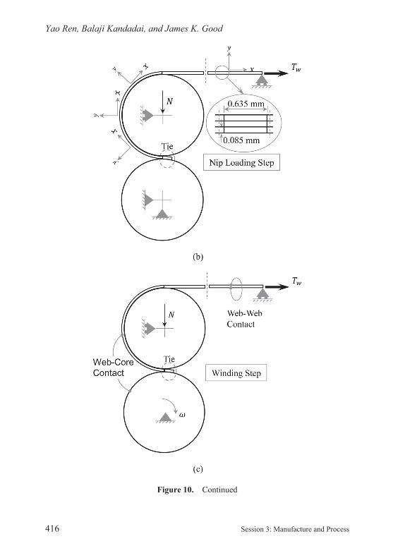
As a winding operation starts, the incoming layer is rst fastened to the core and tensioned. Second, the nip roller approaches the incoming layer on the core and is impinged at a given nip load. Third, the winder begins to rotate with web layers winding in a spiral fashion on the core. To model the center winding condi-tion, the loading procedure in Abaqus/Explicit was also divided into three steps: pretension, nip loading and winding, as shown in Figure 10. In the pretension step
Figure 10. Modeling Steps for Center Winding using Explicit Analysis.
25770.indb 415 15/08/2013 08:11
Yao Ren, Balaji Kandadai, and James K. Good
416 Session 3: Manufacture and Process
Figure 10. Continued
25770.indb 416 15/08/2013 08:11 25770.indb 417 15/08/2013 08:11

25770.indb 416 15/08/2013 08:11
Center Winding Versus Surface Winding
15th Fundamental Research Symposium, Cambridge, September 2013 417
shown in Figure 10a, the leading end of the incoming web layer is tied to the core in a small area, while the core and nip roller are restrained. The lower end point on the right end surface of the web is restrained vertically (y) such that only hori-zontal (x) displacement is allowed. A constant winding tension Tw is prescribed at the right end surface of the web and is maintained during the simulation. In the nip loading step shown in Figure 10b, the vertical (y) restraint of the nip roller is released. Then a vertical downward concentrated force representing the nip load N was applied at the central reference node of the nip roller and was maintained during the simulation. All other loads and boundary conditions are inherited from the previous step. In the winding step shown in Figure 10c, the rotation of the core about the z axis is released and an angular velocity is assigned to the core. The other loads and boundary conditions remain identical. Modeling surface winding was very similar except the angular velocity in Figure 10c was now input to the nip roller and core/wound roll was free to rotate.
In Figure 10 the potential for surface interaction is shown between the web and the nip, the web upon the core and self- contact of the web winding upon itself. One of the challenges in modeling a winding process using an explicit FE method is to accurately model the surface interactions. This is accomplished by modeling the contact pairs using a kinematic predictor- corrector contact algorithm [15] to strictly enforce the contact constraints that allows for no nodal penetrations. The friction between all contacting surfaces is modeled using Coulomb’s friction law with a constant coef cient of friction. The Coulomb friction model relates the maximum allowable frictional (shear) stress across an interface to the contact pressure between the contacting bodies. In the basic form of the Coulomb friction model, two contacting surfaces can react shear stresses up to a certain magnitude across their interface prior to slipping relative to one another, in a state is known as stick. This is schematically represented in Figure 11.
Figure 11. Coulomb’s Friction Model.
25770.indb 417 15/08/2013 08:11
Yao Ren, Balaji Kandadai, and James K. Good
418 Session 3: Manufacture and Process
The Coulomb friction model de nes this critical shear stress ( crit) as the stress at which sliding of the surfaces starts as a fraction of the contact pressure (p(x)) between the surfaces per expression (10):
(10)
The stick/slip calculations determine when a point in a contact region moves from stick to slip or from slip to stick. This friction law is basic and is sometimes criti-cized due for the critical shear stress being independent of the magnitude of the slip velocity shown in Figure 11. This friction model was used exclusively in these simulations.
As stated before, the explicit method is conditionally stable. Due to low density and the thinness of typical web materials, the stable time increment t is usually very small which makes the solution computationally very expensive. Two tech-niques can be used to accelerate the solution process: increasing loading rates and mass scaling. The former technique arti cially reduces the time duration of physical events to reduce the overall simulation time. The latter arti cially increases the mass of the entire or partial structure to increase the stable time increment t. In this study, both techniques were adopted. First the time dura-tions for applying web tension, nip loads and angular velocity of core were reduced. To overcome the potential noise in solution generated by increasing loading rate, a smooth amplitude function is used to apply these loading in their respective steps to prevent sudden changes in acceleration. Second, a mass scaling factor of 300 is used for the web material, which increases the stable time increment to an order of magnitude around 10–6 s. By using these techniques, the solution time for single winding case is around 15 hours on an Intel Xeon 3.07 GHz workstation.
CENTER VERSUS SURFACE WINDING: CONSTANT ORTHOTROPIC WEB PROPERTIES: HIGH MD MODULUS
The rst focus will be for high modulus materials that would encompass many grades of paper and some plastic lms such as polyester. The web modeled is 254 m thick and the width is 15.24 cm. In these simulations the radius of the nip (Rnip) and the core (Rcore) were 5.08 and 4.29 cm, respectively. The friction coef cient between web layers, between the web and the nip and between the web and the core were all set at 0.3. The 1, 2 and 3 material property directions are related to the machine direction (MD), cross machine direction (CMD) and the radial z direction (ZD) in Figure 12.
25770.indb 418 15/08/2013 08:11 25770.indb 419 15/08/2013 08:11
25770.indb 418 15/08/2013 08:11
Center Winding Versus Surface Winding
15th Fundamental Research Symposium, Cambridge, September 2013 419
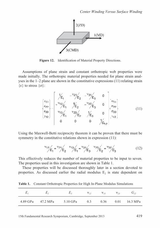
Assumptions of plane strain and constant orthotropic web properties were made initially. The orthotropic material properties needed for plane strain anal-yses in the 1–2 plane are shown in the constitutive expressions (11) relating strain { } to stress { }:
(11)
Using the Maxwell- Betti reciprocity theorem it can be proven that there must be symmetry in the constitutive relations shown in expression (11):
(12)
This effectively reduces the number of material properties to be input to seven. The properties used in this investigation are shown in Table 1.
These properties will be discussed thoroughly later in a section devoted to properties. As discussed earlier the radial modulus E2 is state dependent on
Figure 12. Identi cation of Material Property Directions.
Table 1. Constant Orthotropic Properties for High In- Plane Modulus Simulations
E1 E2 E3 12 13 23 G12
4.89 GPa 47.2 MPa 5.10 GPa 0.3 0.36 0.01 16.3 MPa
25770.indb 419 15/08/2013 08:11
Yao Ren, Balaji Kandadai, and James K. Good
420 Session 3: Manufacture and Process
pressure, expressions (4) and (5) for instance. To speed the computations an average value of E2 was selected for the range of nip loads studied. The constant value of G12 came from an approximation made originally by St. Venant [16]. Later these constant values will be allowed to vary.
Results will be examined rst for a low nip load where slippage is prevalent in the contact zone. Then results will be examined for a high nip load where stick behavior now exists in the contact zone. This section will conclude with a discussion of the resulting WOT that was computed for a range of nip loads and web tensions.
Low Nip Load Behavior
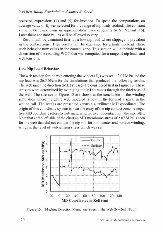
The web tension for the web entering the winder (Tw) was set at 2.07 MPa and the nip load was 26.3 N/cm for the simulations that produced the following results. The web machine direction (MD) stresses are considered rst in Figure 13. These stresses were determined by averaging the MD stresses through the thickness of the web. The stresses in Figure 13 are shown at the conclusion of the winding simulation where the entire web modeled is now in the form of a spiral in the wound roll. The results are presented versus a curvilinear MD coordinate. The origin of this coordinate system is near the entry of the nip contact zone. A nega-tive MD coordinate refers to web material prior to or in contact with the nip roller. Note that at the left side of the chart an MD membrane stress of 2.07 MPa is seen for the web that did not contact the nip roll for both center and surface winding, which is the level of web tension stress which was set.
Figure 13. Machine Direction Membrane Stress in the Web (N = 26.3 N/cm).
25770.indb 420 15/08/2013 08:11 25770.indb 421 15/08/2013 08:11
25770.indb 420 15/08/2013 08:11
Center Winding Versus Surface Winding
15th Fundamental Research Symposium, Cambridge, September 2013 421
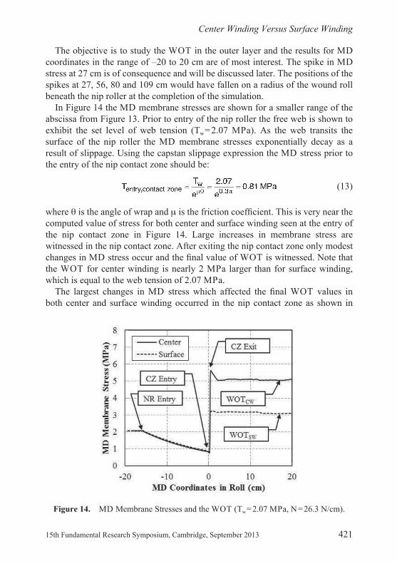
The objective is to study the WOT in the outer layer and the results for MD coordinates in the range of –20 to 20 cm are of most interest. The spike in MD stress at 27 cm is of consequence and will be discussed later. The positions of the spikes at 27, 56, 80 and 109 cm would have fallen on a radius of the wound roll beneath the nip roller at the completion of the simulation.
In Figure 14 the MD membrane stresses are shown for a smaller range of the abscissa from Figure 13. Prior to entry of the nip roller the free web is shown to exhibit the set level of web tension (Tw = 2.07 MPa). As the web transits the surface of the nip roller the MD membrane stresses exponentially decay as a result of slippage. Using the capstan slippage expression the MD stress prior to the entry of the nip contact zone should be:
(13)
where is the angle of wrap and is the friction coef cient. This is very near the computed value of stress for both center and surface winding seen at the entry of the nip contact zone in Figure 14. Large increases in membrane stress are witnessed in the nip contact zone. After exiting the nip contact zone only modest changes in MD stress occur and the nal value of WOT is witnessed. Note that the WOT for center winding is nearly 2 MPa larger than for surface winding, which is equal to the web tension of 2.07 MPa.
The largest changes in MD stress which affected the nal WOT values in both center and surface winding occurred in the nip contact zone as shown in
Figure 14. MD Membrane Stresses and the WOT (Tw = 2.07 MPa, N = 26.3 N/cm).
25770.indb 421 15/08/2013 08:11
Yao Ren, Balaji Kandadai, and James K. Good
422 Session 3: Manufacture and Process
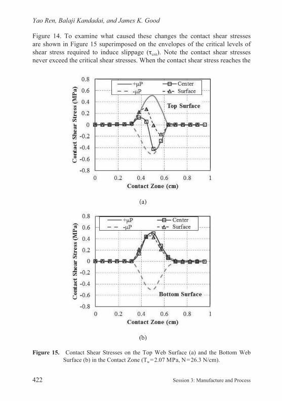
Figure 14. To examine what caused these changes the contact shear stresses are shown in Figure 15 superimposed on the envelopes of the critical levels of shear stress required to induce slippage ( crit). Note the contact shear stresses never exceed the critical shear stresses. When the contact shear stress reaches the
Figure 15. Contact Shear Stresses on the Top Web Surface (a) and the Bottom Web Surface (b) in the Contact Zone (Tw = 2.07 MPa, N = 26.3 N/cm).
25770.indb 422 15/08/2013 08:11 25770.indb 423 15/08/2013 08:11

25770.indb 422 15/08/2013 08:11
Center Winding Versus Surface Winding
15th Fundamental Research Symposium, Cambridge, September 2013 423
critical shear stress slippage will result. In cases where the contact shear stress is less than the critical value stick behavior will result. Slip is occurring through the entire contact zone on the lower surface for both center and surface winding as shown in Figure 15b. The lower surface is in contact with the previous layer that was wound onto the roll. The behavior on the upper surface however is markedly different with slip occurring near the entry and exit but separated by a zone of stick. It is also evident that the contact shear stresses differ between center and surface winding on the upper surface. The upper web surface is in direct contact with the surface of the nip roller. Equilibrium can be established for the web in the contact zone if the contact shear stresses are integrated on the upper and lower surfaces as shown in Figure 16.
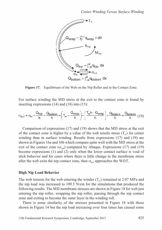
Now the difference between center and surface winding becomes quanti able. The major difference is the sign and magnitude of the shear traction on the upper surface of the web in the contact zone. It is this difference which is responsible for the majority of the 2.24 MPa difference in out, which is approximately the value of the web tension (Tw) 2.07 MPa. This is consistent with what the empirically derived expressions (1) and (2) forecast as the difference in WOT between center and surface winding. Why this difference occurs is dif cult to understand when considering how similar the values of in were for both center and surface winding as demonstrated in Figures 14 and 16. If equilibrium is considered on another scale, as shown in Figure 17, this difference can be explained.
The rst focus is equilibrium of the web on the surface of the nip roller prior to the nip contact zone:
(14)
Equilibrium must also be sustained for the web in the contact zone:
(15)
For center winding, the torque applied to the nip (Mnip) is zero. The applied surface tractions acting on the nip roller must be in equilibrium:
(16)
For center winding the MD stress at the exit to the contact zone is found by inserting expressions (14) and (16) into (15):
(17)
25770.indb 423 15/08/2013 08:11

Yao Ren, Balaji Kandadai, and James K. Good
424 Session 3: Manufacture and Process
For surface winding, a torque (Mnip) must be applied to wind the roll. The torque will be approximately the web tension, in units of force, multiplied by the radius of the nip (Rnip). Again the applied surface tractions acting on the nip roller must be in equilibrium with the applied torque:
(18)
Figure 16. Equilibrium of Web in Contact Zone, Tw = 2.07 MPa, N = 26.3 N/cm.
25770.indb 424 15/08/2013 08:11 25770.indb 425 15/08/2013 08:11
25770.indb 424 15/08/2013 08:11
Center Winding Versus Surface Winding
15th Fundamental Research Symposium, Cambridge, September 2013 425
For surface winding the MD stress at the exit to the contact zone is found by inserting expressions (14) and (18) into (15):
(19)
Comparison of expressions (17) and (19) shows that the MD stress at the exit of the contact zone is higher by a value of the web tensile stress (Tw) for center winding than in surface winding. Results from expressions (17) and (19) are shown in Figures 16a and 16b which compare quite well with the MD stress at the exit of the contact zone ( out) computed by Abaqus. Expressions (17) and (19) become expressions (1) and (2) only when the lower contact surface is void of stick behavior and for cases where there is little change in the membrane stress after the web exits the nip contact zone, then out approaches the WOT.
High Nip Load Behavior
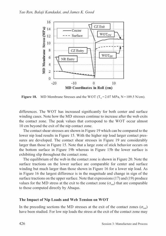
The web tension for the web entering the winder (Tw) remained at 2.07 MPa and the nip load was increased to 109.5 N/cm for the simulations that produced the following results. The MD membrane stresses are shown in Figure 18 for web just entering the nip roller, wrapping the nip roller, passing through the nip contact zone and exiting to become the outer layer in the winding roll.
There is some similarity of the stresses presented in Figure 18 with those shown in Figure 14 but the nip load increasing over four times has caused some
Figure 17. Equilibrium of the Web on the Nip Roller and in the Contact Zone.
25770.indb 425 15/08/2013 08:11
Yao Ren, Balaji Kandadai, and James K. Good
426 Session 3: Manufacture and Process
differences. The WOT has increased signi cantly for both center and surface winding cases. Note how the MD stresses continue to increase after the web exits the contact zone. The peak values that correspond to the WOT occur almost 10 cm beyond the exit of the nip contact zone.
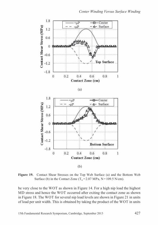
The contact shear stresses are shown in Figure 19 which can be compared to the lower nip load results in Figure 15. With the higher nip load larger contact pres-sures are developed. The contact shear stresses in Figure 19 are considerably larger than those in Figure 15. Note that a large zone of stick behavior occurs on the bottom surface in Figure 19b whereas in Figure 15b the lower surface is exhibiting slip throughout the contact zone.
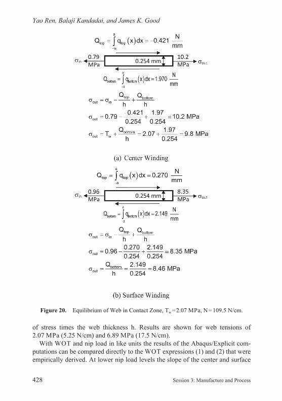
The equilibrium of the web in the contact zone is shown in Figure 20. Note the surface tractions on the lower surface are comparable for center and surface winding but much larger than those shown in Figure 16 for a lower nip load. As in Figure 16 the largest difference is in the magnitude and change in sign of the surface tractions on the upper surface. Note that expressions (17) and (19) produce values for the MD stress at the exit to the contact zone ( out) that are comparable to those computed directly by Abaqus.
The Impact of Nip Loads and Web Tension on WOT
In the preceding sections the MD stresses at the exit of the contact zones ( out) have been studied. For low nip loads the stress at the exit of the contact zone may
Figure 18. MD Membrane Stresses and the WOT (Tw = 2.07 MPa, N = 109.5 N/cm).
25770.indb 426 15/08/2013 08:11 25770.indb 427 15/08/2013 08:11
25770.indb 426 15/08/2013 08:11
Center Winding Versus Surface Winding
15th Fundamental Research Symposium, Cambridge, September 2013 427
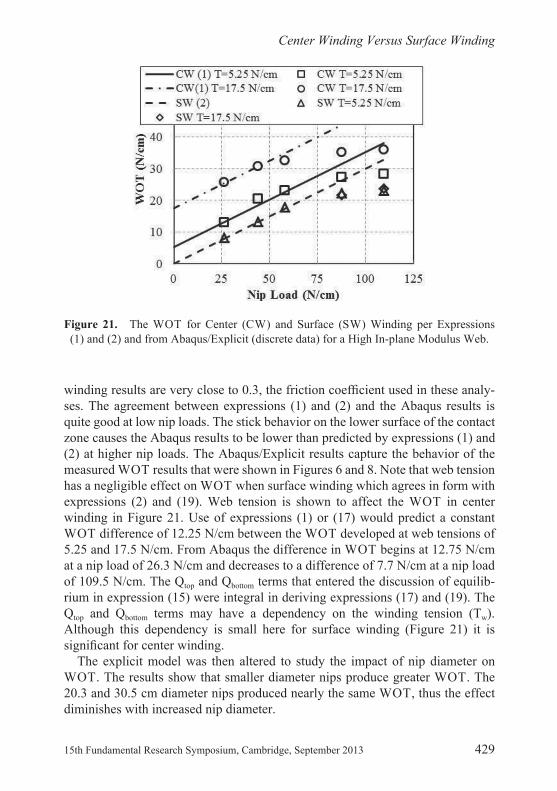
be very close to the WOT as shown in Figure 14. For a high nip load the highest MD stress and hence the WOT occurred after exiting the contact zone as shown in Figure 18. The WOT for several nip load levels are shown in Figure 21 in units of load per unit width. This is obtained by taking the product of the WOT in units
Figure 19. Contact Shear Stresses on the Top Web Surface (a) and the Bottom Web Surface (b) in the Contact Zone (Tw = 2.07 MPa, N = 109.5 N/cm).
25770.indb 427 15/08/2013 08:11
Yao Ren, Balaji Kandadai, and James K. Good
428 Session 3: Manufacture and Process
of stress times the web thickness h. Results are shown for web tensions of 2.07 MPa (5.25 N/cm) and 6.89 MPa (17.5 N/cm).
With WOT and nip load in like units the results of the Abaqus/Explicit com -putations can be compared directly to the WOT expressions (1) and (2) that were empirically derived. At lower nip load levels the slope of the center and surface
Figure 20. Equilibrium of Web in Contact Zone, Tw = 2.07 MPa, N = 109.5 N/cm.
25770.indb 428 15/08/2013 08:11 25770.indb 429 15/08/2013 08:11
25770.indb 428 15/08/2013 08:11
Center Winding Versus Surface Winding
15th Fundamental Research Symposium, Cambridge, September 2013 429
winding results are very close to 0.3, the friction coef cient used in these analy- ses. The agreement between expressions (1) and (2) and the Abaqus results is quite good at low nip loads. The stick behavior on the lower surface of the contact zone causes the Abaqus results to be lower than predicted by expressions (1) and (2) at higher nip loads. The Abaqus/Explicit results capture the behavior of the measured WOT results that were shown in Figures 6 and 8. Note that web tension has a negligible effect on WOT when surface winding which agrees in form with expressions (2) and (19). Web tension is shown to affect the WOT in center winding in Figure 21. Use of expressions (1) or (17) would predict a constant WOT difference of 12.25 N/cm between the WOT developed at web tensions of 5.25 and 17.5 N/cm. From Abaqus the difference in WOT begins at 12.75 N/cm at a nip load of 26.3 N/cm and decreases to a difference of 7.7 N/cm at a nip load of 109.5 N/cm. The Qtop and Qbottom terms that entered the discussion of equilib-rium in expression (15) were integral in deriving expressions (17) and (19). The Qtop and Qbottom terms may have a dependency on the winding tension (Tw). Although this dependency is small here for surface winding (Figure 21) it is signi cant for center winding.
The explicit model was then altered to study the impact of nip diameter on WOT. The results show that smaller diameter nips produce greater WOT. The 20.3 and 30.5 cm diameter nips produced nearly the same WOT, thus the effect diminishes with increased nip diameter.
Figure 21. The WOT for Center (CW) and Surface (SW) Winding per Expressions (1) and (2) and from Abaqus/Explicit (discrete data) for a High In- plane Modulus Web.
25770.indb 429 15/08/2013 08:11

Yao Ren, Balaji Kandadai, and James K. Good
430 Session 3: Manufacture and Process
CENTER VERSUS SURFACE WINDING: CONSTANT ORTHOTROPIC WEB PROPERTIES: LOW IN- PLANE MODULUS
The impact of a low in- plane modulus on WOT is signi cant. Additional explicit analyses were conducted where all properties remained the same per Table 1 except the MD and CMD modulus as shown in Table 2. This modulus is similar to what might be expected for a tissue, non- woven or a low density polyethylene web.
The MD membrane stresses in the vicinity of the nip contact zone are shown in Figure 23 for two web tensions and a nip load of 87.6 N/cm. These can be compared to the MD membrane stresses for high in- plane modulus webs in Figure 14. One apparent difference is that prior to the nip contact zone entry the MD membrane stress is essentially that of web tension (Tw). Thus the slippage of the web that wrapped the nip roller that was witnessed for high in- plane modulus webs in Figure 14 is much reduced for the low in- plane modulus web in
Figure 22. The Effect of Nip Diameter on WOT for Center Winding per Expressions (1) and Abaqus/Explicit (discrete data).
Table 2. Constant Orthotropic Properties for Low In- Plane Modulus Simulations
E1 E2 E3 12 13 23 G12
138 MPa 47.2 MPa 138 MPa 0.3 0.3 0.01 16.3 MPa
25770.indb 430 15/08/2013 08:11 25770.indb 431 15/08/2013 08:11
25770.indb 430 15/08/2013 08:11
Center Winding Versus Surface Winding
15th Fundamental Research Symposium, Cambridge, September 2013 431
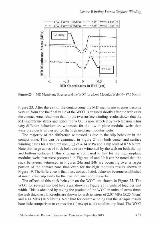
Figure 23. After the exit of the contact zone the MD membrane stresses become very uniform and the nal value of the WOT is attained shortly after the web exits the contact zone. Also note that for the two surface winding results shown that the MD membrane stress and hence the WOT is now affected by web tension. Thus very different behaviors are witnessed for the low in- plane modulus webs than were previously witnessed for the high in- plane modulus webs.
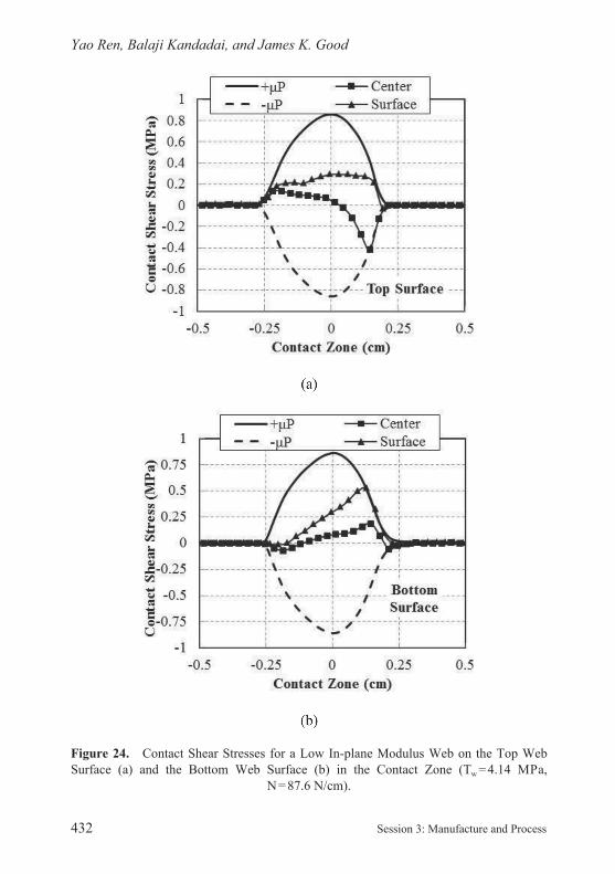
The majority of the difference witnessed is due to the slip behavior in the contact zone. This can be examined in Figure 24 for both center and surface winding cases for a web tension (Tw) of 4.14 MPa and a nip load of 87.6 N/cm. Note that large zones of stick behavior are witnessed by the web on both the top and bottom surfaces. If this slippage is compared to that for the high in- plane modulus webs that were presented in Figures 15 and 19 it can be noted that the stick behaviors witnessed in Figures 24a and 24b are occurring over a larger portion of the contact zone than even for the high modulus results shown in Figure 19. The difference is that these zones of stick behavior become established at much lower nip loads for the low in- plane modulus webs.
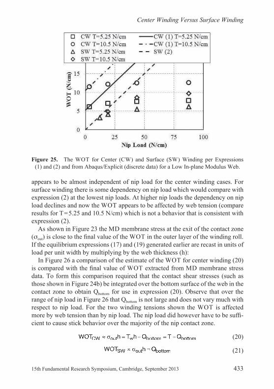
The effects of this stick behavior on the WOT are shown in Figure 25. The WOT for several nip load levels are shown in Figure 25 in units of load per unit width. This is obtained by taking the product of the WOT in units of stress times the web thickness h. Results are shown for web tensions of 2.07 MPa (5.25 N/cm) and 4.14 MPa (10.5 N/cm). Note that for center winding that the Abaqus results bare little comparison to expression (1) except at the smallest nip load. The WOT
Figure 23. MD Membrane Stresses and the WOT for a Low Modulus Web (N = 87.6 N/cm).
25770.indb 431 15/08/2013 08:11
Yao Ren, Balaji Kandadai, and James K. Good
432 Session 3: Manufacture and Process
Figure 24. Contact Shear Stresses for a Low In- plane Modulus Web on the Top Web Surface (a) and the Bottom Web Surface (b) in the Contact Zone (Tw = 4.14 MPa,
N = 87.6 N/cm).
25770.indb 432 15/08/2013 08:11 25770.indb 433 15/08/2013 08:11
25770.indb 432 15/08/2013 08:11
Center Winding Versus Surface Winding
15th Fundamental Research Symposium, Cambridge, September 2013 433
appears to be almost independent of nip load for the center winding cases. For surface winding there is some dependency on nip load which would compare with expression (2) at the lowest nip loads. At higher nip loads the dependency on nip load declines and now the WOT appears to be affected by web tension (compare results for T = 5.25 and 10.5 N/cm) which is not a behavior that is consistent with expression (2).
As shown in Figure 23 the MD membrane stress at the exit of the contact zone ( out) is close to the nal value of the WOT in the outer layer of the winding roll. If the equilibrium expressions (17) and (19) generated earlier are recast in units of load per unit width by multiplying by the web thickness (h):
In Figure 26 a comparison of the estimate of the WOT for center winding (20) is compared with the nal value of WOT extracted from MD membrane stress data. To form this comparison required that the contact shear stresses (such as those shown in Figure 24b) be integrated over the bottom surface of the web in the contact zone to obtain Qbottom for use in expression (20). Observe that over the range of nip load in Figure 26 that Qbottom is not large and does not vary much with respect to nip load. For the two winding tensions shown the WOT is affected more by web tension than by nip load. The nip load did however have to be suf -cient to cause stick behavior over the majority of the nip contact zone.
(20)
(21)
Figure 25. The WOT for Center (CW) and Surface (SW) Winding per Expressions (1) and (2) and from Abaqus/Explicit (discrete data) for a Low In- plane Modulus Web.
25770.indb 433 15/08/2013 08:11

Yao Ren, Balaji Kandadai, and James K. Good
434 Session 3: Manufacture and Process
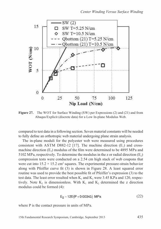
In Figure 27 a comparison of the estimate of the WOT for surface winding (21) is compared with the nal value of WOT extracted from MD membrane stress data. Note at lower nip loads the WOT behavior becomes similar to that given by expression (2). Again the results that show the WOT is affected by web tension (T) are not consistent with expression (2). Through expression (21) it is apparent that the WOT is in uenced by web tension (T) but by affecting Qbottom.
Expressions (20) and (21) are approximations for the nal value of the WOT. The expressions through equilibrium should exactly predict the web tension at the exit of the contact zone. While simplistic in form expressions (20) and (21) both rely upon knowledge of Qbottom. To determine Qbottom requires the contact mechanics analyses which in this case were performed using Abaqus/Explicit. The explicit analyses also determine if there will be additional slippage between the outer layer and the layer beneath after the exit of the nip contact zone which will affect the nal value of the WOT.
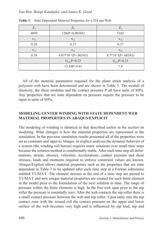
STATE DEPENDENT WEB MATERIAL PROPERTIES
It has been well documented that some orthotropic web properties are constant for many webs, the MD and CMD modulus for example. Other properties are not well documented. The purpose of this section is to fully document the properties of the 254 m polyester web. These properties will be used in explicit simulations and then
Figure 26. The WOT for Center Winding (CW) per Expressions (1) and (20) and from Abaqus/Explicit (discrete data) for a Low In- plane Modulus Web.
25770.indb 434 15/08/2013 08:11 25770.indb 435 15/08/2013 08:11
25770.indb 434 15/08/2013 08:11
Center Winding Versus Surface Winding
15th Fundamental Research Symposium, Cambridge, September 2013 435
compared to test data in a following section. Seven material constants will be needed to fully de ne an orthotropic web material undergoing plane strain analysis.
The in- plane moduli for the polyester web were measured using procedures consistent with ASTM D882- 12 [17]. The machine direction (E1) and cross- machine direction (E3) modulus of the lm were determined to be 4895 MPa and 5102 MPa, respectively. To determine the modulus in the z or radial direction (E2) compression tests were conducted on a 2.54 cm high stack of web coupons that were cut into 15.2 × 15.2 cm2 squares. The experimental pressure- strain behavior along with Pfeiffer curve t (3) is shown in Figure 28. A least squared error routine was used to provide the best possible t of Pfeiffer’s expression (3) to the test data. The least error resulted when K1 and K2 were 3.45 KPa and 120, respec-tively. Note K2 is dimensionless. With K1 and K2 determined the z direction modulus could be formed (4):
(22)
where P is the contact pressure in units of MPa.
Figure 27. The WOT for Surface Winding (SW) per Expressions (2) and (21) and from Abaqus/Explicit (discrete data) for a Low In- plane Modulus Web.
25770.indb 435 15/08/2013 08:11

Yao Ren, Balaji Kandadai, and James K. Good
436 Session 3: Manufacture and Process
A value of the in- plane Poisson ration 13 was taken at 0.36, consistent with tests conducted using ASTM D638- 10 [18, 19]. The Poisson ratios 12 and 32 were not evident in the literature and a test was devised to determine the values. A web was subjected to a tensile strain in the machine direction ( 1) in a material testing system as shown in Figure 29.
Figure 28. E2 Stack Compression Test.
Figure 29. Test Setup for Measurement of Poisson Ratio.
25770.indb 436 15/08/2013 08:11 25770.indb 437 15/08/2013 08:11

25770.indb 436 15/08/2013 08:11
Center Winding Versus Surface Winding
15th Fundamental Research Symposium, Cambridge, September 2013 437
The strain was measured in the z or 2 direction by measuring the change in capacitance between the two precision ground aluminum plates shown. The plates were held in contact with the web with light clamping pressure. For a parallel plate capacitor the capacitance is:
(23)
where o is the permittivity of space (8.854*10–12 F/m), k is the dielectric of poly-ester (taken as 3 [20] for polyester), A is the area of the aluminum plates and h is the separation of the plates and is also the deformed web thickness. Expression (23) can be rearranged to infer the web thickness (h) which will decrease as the strain in the machine direction strain increases. The strain in the z or 2 direction can then be inferred from the measured changes in capacitance:
(24)
where h0 and h1 are the unstrained web thickness and the deformed web thickness at an MD strain ( 1) level. C0 and C1 are the capacitances measured when the web was unstrained and then strained in the MD at level 1, respectively.
The results of such a test are shown in Figure 30. The slope is reasonably
Figure 30. Strain Data Used to Discern 12.
25770.indb 437 15/08/2013 08:11

Yao Ren, Balaji Kandadai, and James K. Good
438 Session 3: Manufacture and Process
Figure 31. Test Setup for Investigation of G12 as a Function of Stack Pressure.
constant considering the friction that is involved in the test. For a web subject to uniaxial stress in the MD, 12 can be determined from the slope:
(25)
This is essentially equal to the in- plane value ( 13) of 0.36 taken from the literature. 32 was also taken as 0.37.
The shear modulus G12 was also needed. The shear modulus of thick board grades of paper were studied by Stenberg [21]. The apparatus used measured a value of the shear modulus for a single board sheet. With the radial modulus E2 known to be dependent on pressure (22) was it possible that the shear modulus was as well? To explore such behavior required the ability to set and control the pressure at varied levels in a stack of web coupons while investigating the shear modulus. A study ensued in which a stack of web was subjected to set levels of pressure by a material testing system. An electromagnetic shaker harmonically oscillated a steel platen which subjected the web stacks in compression to an oscillatory shear as shown in Figure 31. The frequency of oscillation input to the shaker was varied slowly until an accelerometer (shown) on the opposite side of the platen produced peak output. When this peak was found it was known that the system composed of the web stacks and the steel platen were oscillating at the rst natural frequency in shear. This natural frequency is related to the shear modulus. Thus measurement of the natural frequency allowed the inference of the shear modulus.
25770.indb 438 15/08/2013 08:11 25770.indb 439 15/08/2013 08:11

25770.indb 438 15/08/2013 08:11
Center Winding Versus Surface Winding
15th Fundamental Research Symposium, Cambridge, September 2013 439
This setup can be modeled as a single degree of freedom dynamic system:
(26)
where fn is the natural frequency (hz), H is the height of each web stack and A is the area of the stack, M is the mass of the platen and m is the mass of each of the web stacks, which are assumed identical. Results for the polyester web are shown in Figure 32. Thus the shear modulus is shown to be highly dependent on stack pressure when stack pressure is low but becomes nearly constant at high stack pressure. Although not required for plane strain analyses the shear modulus G32 was also determined using this method. For the polyester web G12 and G32 were essentially equivalent, whether this is true for other webs is currently unknown. It should be noted that the oscillatory shear load input by the electromagnetic shaker was quite small. Had this shear load been substantially larger it would have been possible to cause slip between the stack layers. By using a small oscillatory shear load we ensured that use of expression (26) was valid as no slip was assumed in the derivation. This in no way limits the explicit analyses of winding. The apparent shearing deformation of web layers is governed by expression (26) until the induced shear becomes suf cient to induce slip. After slip begins the shearing deformation within a web layer will still be governed by expression (26) whereas the interlayer slip will be governed by Coulomb friction (10).
Figure 32. Shear Modulus G12 Inferred from Natural Frequency.
25770.indb 439 15/08/2013 08:11
Yao Ren, Balaji Kandadai, and James K. Good
440 Session 3: Manufacture and Process
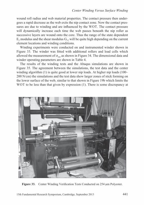
All of the material parameters required for the plane strain analysis of a polyester web have been determined and are shown in Table 3. The moduli of elasticity, the shear modulus and the contact pressure P all have units of MPa. Any properties that are state dependent on pressure require the pressure to be input in units of MPa.
MODELING CENTER WINDING WITH STATE DEPENDENT WEB MATERIAL PROPERTIES IN ABAQUS/EXPLICIT
The modeling of winding is identical to that described earlier in the section on modeling. What changes is how the material properties are represented in the simulation. In the previous simulation results presented all of the properties were set as constants and input to Abaqus. In explicit analyses the dynamic behavior of a system (the winding roll herein) requires many solutions over small time steps because the solution method is conditionally stable. After each time step all defor-mations, strains, stresses, velocities, accelerations, contact pressure and shear stresses, loads and moments required to enforce constraint values are known. Abaqus/Explicit allows material properties such as the properties that are state dependent in Table 3 to be updated after each time step in a Fortran subroutine entitled VUMAT. The element stresses at the end of a time step are passed to VUMAT and new unique material properties are created for each nite element in the model prior to the formulation of the next solution in time. The range of pressure within the nite elements is high. In the free web span prior to the nip roller the pressure is essentially zero. After the web contacts the nip roller there is a small contact pressure between the web and nip roller. Upon entry into the nip contact zone with the wound roll the contact pressure on the upper and lower surface of the web becomes very high and is in uenced by nip load, nip and
Table 3. State Dependent Material Properties for a 254 m Web
E1 E2 E3
4895 120(P+0.00345) 5102
13 12 32
0.36 0.37 0.37
31 21 23
0.38 9.07*10–3(P+.00345) 8.7*10–3(P+.00345)G12,P<0.23 G12,P>0.23
15.54P+4.81 7.8
25770.indb 440 15/08/2013 08:11 25770.indb 441 15/08/2013 08:11
25770.indb 440 15/08/2013 08:11
Center Winding Versus Surface Winding
15th Fundamental Research Symposium, Cambridge, September 2013 441
wound roll radius and web material properties. The contact pressure then under-goes a rapid decrease as the web exits the nip contact zone. Now the contact pres-sures are due to winding and are in uenced by the WOT. The contact pressure will dynamically increase each time the web passes beneath the nip roller as successive layers are wound onto the core. Thus the range of the state dependent E2 modulus and the shear modulus G12 will be quite high depending on the current element locations and winding conditions.
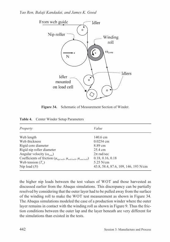
Winding experiments were conducted on and instrumented winder shown in Figure 33. The winder was tted with additional rollers and load cells which allowed the measurement of out as shown in Figure 34. The dimensional data and winder operating parameters are shown in Table 4.
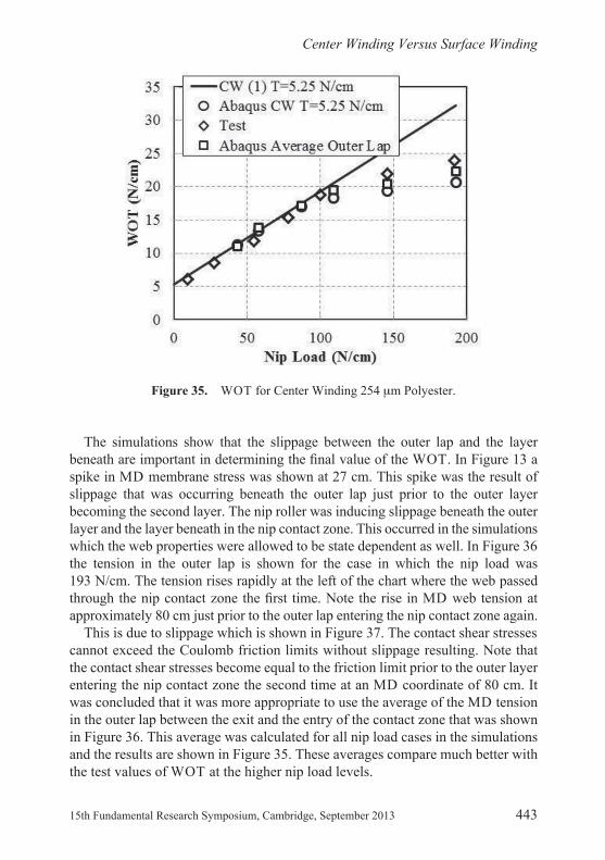
The results of the winding tests and the Abaqus simulations are shown in Figure 35. The agreement between the simulations, the test data and the center winding algorithm (1) is quite good at lower nip loads. At higher nip loads (100–200 N/cm) the simulations and the test data show larger zones of stick forming on the lower surface of the web, similar to that shown in Figure 19b which limits the WOT to be less than that given by expression (1). There is some discrepancy at
Figure 33. Center Winding Veri cation Tests Conducted on 254 m Polyester.
25770.indb 441 15/08/2013 08:11
Yao Ren, Balaji Kandadai, and James K. Good
442 Session 3: Manufacture and Process
the higher nip loads between the test values of WOT and those harvested as discussed earlier from the Abaqus simulations. This discrepancy can be partially resolved by considering that the outer layer had to be pulled away from the surface of the winding roll to make the WOT test measurement as shown in Figure 34. The Abaqus simulations modeled the case of a production winder where the outer layer remains in contact with the winding roll as shown in Figure 9. Thus the fric-tion conditions between the outer lap and the layer beneath are very different for the simulations than existed in the tests.
Figure 34. Schematic of Measurement Section of Winder.
Table 4. Center Winder Setup Parameters
Property Value
Web length 140.6 cmWeb thickness 0.0254 cmRigid core diameter 8.89 cmRigid nip roller diameter 25.4 cmAngular velocity ( core) 2 rad/secCoef cients of friction ( nip/web, web/web, core/web) 0.18, 0.16, 0.18Web tension (Tw) 5.25 N/cmNip load (N) 43.8, 58.4, 87.6, 109, 146, 193 N/cm
25770.indb 442 15/08/2013 08:11 25770.indb 443 15/08/2013 08:11
25770.indb 442 15/08/2013 08:11
Center Winding Versus Surface Winding
15th Fundamental Research Symposium, Cambridge, September 2013 443
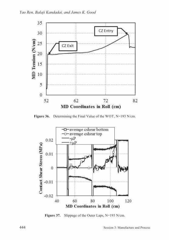
The simulations show that the slippage between the outer lap and the layer beneath are important in determining the nal value of the WOT. In Figure 13 a spike in MD membrane stress was shown at 27 cm. This spike was the result of slippage that was occurring beneath the outer lap just prior to the outer layer becoming the second layer. The nip roller was inducing slippage beneath the outer layer and the layer beneath in the nip contact zone. This occurred in the simulations which the web properties were allowed to be state dependent as well. In Figure 36 the tension in the outer lap is shown for the case in which the nip load was 193 N/cm. The tension rises rapidly at the left of the chart where the web passed through the nip contact zone the rst time. Note the rise in MD web tension at approximately 80 cm just prior to the outer lap entering the nip contact zone again.
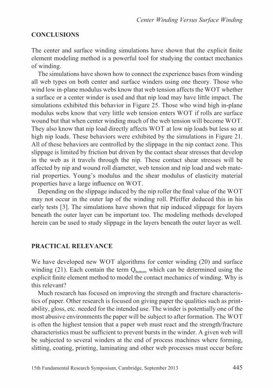
This is due to slippage which is shown in Figure 37. The contact shear stresses cannot exceed the Coulomb friction limits without slippage resulting. Note that the contact shear stresses become equal to the friction limit prior to the outer layer entering the nip contact zone the second time at an MD coordinate of 80 cm. It was concluded that it was more appropriate to use the average of the MD tension in the outer lap between the exit and the entry of the contact zone that was shown in Figure 36. This average was calculated for all nip load cases in the simulations and the results are shown in Figure 35. These averages compare much better with the test values of WOT at the higher nip load levels.
Figure 35. WOT for Center Winding 254 m Polyester.
25770.indb 443 15/08/2013 08:11
Yao Ren, Balaji Kandadai, and James K. Good
444 Session 3: Manufacture and Process
Figure 36. Determining the Final Value of the WOT, N=193 N/cm.
Figure 37. Slippage of the Outer Laps, N=193 N/cm.
25770.indb 444 15/08/2013 08:11 25770.indb 445 15/08/2013 08:11
25770.indb 444 15/08/2013 08:11
Center Winding Versus Surface Winding
15th Fundamental Research Symposium, Cambridge, September 2013 445
CONCLUSIONS
The center and surface winding simulations have shown that the explicit nite element modeling method is a powerful tool for studying the contact mechanics of winding.
The simulations have shown how to connect the experience bases from winding all web types on both center and surface winders using one theory. Those who wind low in- plane modulus webs know that web tension affects the WOT whether a surface or a center winder is used and that nip load may have little impact. The simulations exhibited this behavior in Figure 25. Those who wind high in- plane modulus webs know that very little web tension enters WOT if rolls are surface wound but that when center winding much of the web tension will become WOT. They also know that nip load directly affects WOT at low nip loads but less so at high nip loads. These behaviors were exhibited by the simulations in Figure 21. All of these behaviors are controlled by the slippage in the nip contact zone. This slippage is limited by friction but driven by the contact shear stresses that develop in the web as it travels through the nip. These contact shear stresses will be affected by nip and wound roll diameter, web tension and nip load and web mate-rial properties. Young’s modulus and the shear modulus of elasticity material properties have a large in uence on WOT.
Depending on the slippage induced by the nip roller the nal value of the WOT may not occur in the outer lap of the winding roll. Pfeiffer deduced this in his early tests [3]. The simulations have shown that nip induced slippage for layers beneath the outer layer can be important too. The modeling methods developed herein can be used to study slippage in the layers beneath the outer layer as well.
PRACTICAL RELEVANCE
We have developed new WOT algorithms for center winding (20) and surface winding (21). Each contain the term Qbottom which can be determined using the explicit nite element method to model the contact mechanics of winding. Why is this relevant?
Much research has focused on improving the strength and fracture characteris-tics of paper. Other research is focused on giving paper the qualities such as print-ability, gloss, etc. needed for the intended use. The winder is potentially one of the most abusive environments the paper will be subject to after formation. The WOT is often the highest tension that a paper web must react and the strength/fracture characteristics must be suf cient to prevent bursts in the winder. A given web will be subjected to several winders at the end of process machines where forming, slitting, coating, printing, laminating and other web processes must occur before
25770.indb 445 15/08/2013 08:11
Yao Ren, Balaji Kandadai, and James K. Good
446 Session 3: Manufacture and Process
the paper can become a nal consumer product. A given web will be potentially subject to damage in any one of these winding operations.
The relevance of the research reported herein is that we can now predict what the paper is subjected to in the winder. Furthermore we can distinguish how different winder types (center or surface) and operating parameters will interact with the paper properties to produce WOT and the residual stresses in the wound roll. With this knowledge we can now compute optimal levels for web tension and nip loads to prevent the WOT from exceeding the web strength and damaging the web. In the past, winding equipment was selected when a process machine was con gured based upon an experience base. This qualitative experience base was developed by knowing what winding methods had been successfully employed on webs which were thought similar to the webs which would be potentially trans-ported on a new process machine. As engineers and scientists we seek to move knowledge from qualitative to quantitative levels. We do this because we know that as new paper webs are developed that they can fall outside of experience bases and result in either disaster or suboptimal performance during processing or in a winder. The science has advanced to the quantitative level regarding how a unique web will behave in a winder. This research has focused on assessing WOT but there is other potential. An example is web slippage. In Figure 14 the web was shown to be experiencing slippage throughout the 180 degrees of wrap with the nip roller. Those who are developing webs with high gloss may nd this surface abrasion is detrimental to the web surface quality they were trying to achieve. The largest contact shear stresses the web is subjected to in winding are seen in the nip contact zone as shown in Figures 15, 19 and 24. Even though the nip contact zone is small these contact shear stresses can be high and cause surface damage to the web. Now winder type and set points for web tension, nip load and nip roller characteristics can be studied using the methods herein to determine how slippage and abrasion could be limited to prevent damage to a unique web.
REFERENCES
1. J.K. Good, J.D. Pfeiffer and R.M. Giachetto. Losses in wound- on- tension in the center winding of wound rolls. In Proceedings of the Web Handling Symposium, ASME Applied Mechanics Division, AMD 149:1–12, 1992.
2. J.D. Pfeiffer. Internal pressures in a wound roll of paper. Tappi J. 49(8):342–347, 1966.
3. J.D. Pfeiffer. Mechanics of a rolling nip on paper webs. Tappi J. 51(8):77A–85A, 1968.
4. T. Rand and L.G. Ericsson. Physical properties of newsprint rolls during winding. Tappi J. 56(6):153–156, 1973.
25770.indb 446 15/08/2013 08:11 25770.indb 447 15/08/2013 08:11
25770.indb 446 15/08/2013 08:11
Center Winding Versus Surface Winding
15th Fundamental Research Symposium, Cambridge, September 2013 447
5. J.D. Pfeiffer. Nip forces and their effect on wound- in tension. Tappi J. 60(2):115–117, 1977.
6. J.D. Pfeiffer. Wound- off tension measurement in paper rolls. Tappi J. 60(3):106–108, 1977.
7. J.K. Good and M.W.R. Fikes. Predicting the internal stresses in center wound rolls with an undriven nip roller. Tappi J. 74(6):101–109, 1991.
8. Z. Hakiel. Nonlinear model for wound roll stresses. Tappi J. 70(5):113–117, 1987. 9. R.E. Steves. The effect of nip load on wound- on- tension in surface winding, M.S.
thesis, Oklahoma State University, Stillwater, OK, USA, 1995.10. J.K. Good, J. Hartwig, and R. Markum. A comparison of center and surface winding
using the wound- in- tension method. In Proceedings of the Fifth International Confer-ence on Web Handling, pp87–104, Web Handling Research Center, Oklahoma State University, Stillwater, Oklahoma, 1999.
11. M. Jorkama and R. von Hertzen, R. Contact mechanical approach to the winding nip. In Proceedings of the Fifth International Conference on Web Handling, pp39–49, Web Handling Research Center, Oklahoma State University, Stillwater, Oklahoma, 1999.
12. M. Jorkama and R. von Hertzen. Development of web tension in a winding nip. In Proceedings of the Sixth International Conference on Web Handling, pp123–134, Web Handling Research Center, Oklahoma State University, Stillwater, Oklahoma, 2001.
13. M. Jorkama and R. von Hertzen. The mechanism of nip induced tension in winding. J Pulp Pap Sci. 28(8):280–284, 2002.
14. P.D. Panagiotopoulos. A nonlinear programming approach to the unilateral contact and friction- boundary value problem in the theory of elasticity. Ingenieur Archiv 44:421–432, 1975.
15. Hibbitt, Karlsson, and Sorenson. Abaqus Theory Manual, Pawtucket, RI, USA, 2012.
16. S. Cheng and C.C. Cheng. Relation between E, , G and invariants of the elastic coef- cients for an orthotropic body. The Winter Annual Meeting of the American Society
of Mechanical Engineers, 112:63–65, Applied Mechanics Division and the Materials Division, ASME, Dallas, Texas, 1990.
17. ASTM D882–12: Test Method for Tensile Properties of Thin Plastic Sheeting, ASTM International, West Conshohocken, PA 19428–2959, USA.
18. ASTM D638–10: Standard Test Method for Tensile Properties of Plastics, ASTM International, West Conshohocken, PA 19428–2959, USA.
19. Physical- Thermal Properties of Mylar® Polyester Film, DuPont Teijin Films, Hopewell, VA 23860, USA.
20. Electrical Properties of Mylar® Polyester Film, DuPont Teijin Films, Hopewell, VA 23860, USA.
21. N. Stenberg. Mechanical properties in the thickness direction of paper and paperboard, Licentiate’s thesis, Royal Institute of Technology, Stockholm, 1999.
25770.indb 447 15/08/2013 08:11

15th Fundamental Research Symposium, Cambridge, September 2013
CENTER WINDING VERSUS SURFACE WINDING: THE EFFECT OF WINDER
TYPE AND WEB MATERIAL PROPERTIES ON WOUND ROLL
STRESSES
Yao Ren, Balaji Kandadai, and James K. GoodMechanical & Aerospace Engineering, Oklahoma State University
Stillwater, OK, USA
Bill Sampson University of Manchester (from the chair)
I’d like to ask about out-of-plane Poisson’s ratio; you were using a value of around 0.35?
Keith Good
For the value that connects a stress in the machine direction to a change in thickness, they were that high.
Bill Sampson
Yet there is quite a lot of literature that would suggest that there is actually a negative Poisson’s ratio in the z-direction?
Keith Good
I have actually measured negative values in a stack, but to measure the stack value, you are trying to measure the change in width of the stack and the edge of the stack is rough because you cannot align all the layers. So if you’re trying to do a good job with this, you are tracking the width change of one layer as it is being
Transcription of Discussion
Discussion
Session 3
compressed down in the stack, and that is dif cult. I have seen the value being slightly positive and also slightly negative, but it is always really close to zero.
Pooya Saketi Tampere University of Technology
I have a comment regarding the slippage problem that you have when you are winding paper rolls. As a suggestion, I think it would be good to consult the car manufacturers, because understanding of traction control between car and road has been very well developed in that industry. Perhaps it would be possible to utilise that existing knowledge and add it to these measurements?
Keith Good
I can tell you that some of my latest research projects revolves around coverings on the nip roller, whether they might be elastomers or other things with low Poisson’s ratio.