cartridge filter - images-na.ssl-images-amazon.com · clean and clear® plus cartridge filter...
TRANSCRIPT

CLEAN AND CLEAR® PLUSCARTRIDGE FILTER
IMPORTANT SAFETY INSTRUCTIONSREAD AND FOLLOW ALL INSTRUCTIONSSAVE THESE INSTRUCTIONS
INSTALLATION ANDUSER’S GUIDE

CLEAN AND CLEAR® PLUS Cartridge Filter Installation and User’s Guide
i
P/N 178558 Rev. N 6/15/15
If you have questions about ordering Pentair Aquatic Systems™ replacement parts, and pool products, please contact:
CUSTOMER SERVICE / TECHNICAL SUPPORT
Customer Service and Technical Support, USA (8 A.M. to 7:30 P.M. — Eastern Time)
Phone: (800) 831-7133
Fax: (800) 284-4151
Web siteVisit www.pentairpool.com or www.staritepool.com for information about Pentair products.
TABLE OF CONTENTS
Important Warnings and Safety Precautions ...........................................
Section I: Filter Installation .....................
General Information
Section II: Filter Operation and Cleaning .................................................
General InformationClamp Installation InstructionsSystem Restart InstructionsCleaning Filter ManuallyReplacing Filter CartridgesCleaning the Manual Air Relief Valve
ii
1
1
2
234566
Section III: Troubleshooting ....................
Section IV: Technical Data .......................
Flow Rates
Section V: Replacement Parts .................
Illustrated Parts ViewParts List
6
8
8
9
910

CLEAN AND CLEAR® PLUS Cartridge Filter Installation and User’s Guide
Consumer Information and Safety This filter is designed and manufactured to provide many years of safe and reliable service when installed, operated and maintained according to the information in this manual and the installation codes referred to in later sections. Throughout the manual, safety warnings and cautions are identified by the “ “ symbol. Be sure to read and comply with all of the warnings and cautions.
Before installing this product, read and follow all warning notices and instructions which are included. Failure to follow safety warnings and instructions can result in severe injury, death, or property damage. Call (800) 831-7133 for additional free copies of these instructions or replacement safety labels.
Due to the potential risk that can be involved it is recommended that the pressure test be kept to the minimum time required by the local code. Do not allow people to work around the system when the circulation system is under pressure test. Post appropriate warning signs and establish a barrier around the pressurized equipment. If the equipment is located in an equipment room, lock the door and post a warning sign.
Never attempt to adjust any closures or lids or attempt to remove or tighten bolts when the system is pressurized. These actions can cause the filter to separate and could cause severe personal injury or death if they were to strike a person.
IMPORTANT WARNING AND SAFETY INSTRUCTIONS
IMPORTANT NOTICE: This guide provides installation and operation instructions for the Clean and Clear® Plus Cartridge Filter. Consult Pentair Water Pool and Spa, Inc. with any questions regarding this equipment.
Attention Installer: This guide contains important information about the installation, operation and safe usage of this product. This information should be given to the owner and/or operator of this equipment after installation.Attention User: This manual contains important information that will help you in operating and maintaining this filter. Please retain it for future reference.
This is the safety alert symbol. When you see this symbol on your system or in this manual, look for one of the following signal words and be alert to the potential for personal injury.
Warns about hazards that can cause death, serious personal injury, or major property damage if ignored.
Warns about hazards that may cause death, serious personal injury, or major property damage if ignored.
Warns about hazards that may or can cause minor personal injury or property damage if ignored.
NOTE Indicates special instructions not related to hazards.
Carefully read and follow all safety instructions in this manual and on equipment. Keep safety labels in good condition; replace if missing or damaged.
ii

CLEAN AND CLEAR® PLUS Cartridge Filter Installation and User’s Guide
IMPORTANT WARNING AND SAFETY INSTRUCTIONS
THIS FILTER OPERATES UNDER HIGH PRESSURE When any part of the circulating system, (e.g., closure, pump, filter, valve(s), etc.), is serviced, air can enter
the system and become pressurized. Pressurized air can cause the top closure to separate which can result in severe injury, death, or property damage. To avoid this potential hazard, follow these instructions:
1. If you are not familiar with your pool filtering system and/or heater:
a. Do NOT attempt to adjust or service without consulting your dealer, or a qualified pool technician.
b. Read the entire Installation & User’s Guide before attempting to use, service or adjust the pool filtering system or heater.
2. Before repositioning valve(s) and before beginning the assembly, disassembly, or any other service of the circulating system: (A) Turn the pump OFF and shut OFF any automatic controls to ensure the system is NOT inadvertently started during the servicing; (B) open the manual air bleeder valve; (C) stand clear of the filter; (D) wait until all pressure is relieved; pressure gauge must read zero psi.
3. Whenever installing the filter closure FOLLOW THE FILTER CLOSURE WARNINGS EXACTLY.
4. Once service on the circulating system is complete FOLLOW INITIAL START-UP INSTRUCTIONS EXACTLY.
5. Maintain circulation system properly. Replace worn or damaged parts immediately, (e.g., closure, pressure gauge, valve(s), o-rings, etc).
6. Be sure that the filter is properly mounted and positioned according to instructions provided.
This filter must be installed by a qualified pool serviceman in accordance with all applicable local codes and ordinances. Improper installation could result in death or serious injury to pool users, installers, or others and may also cause damage to property.
Always disconnect power to the pool circulating system at the circuit breaker before servicing the filter. Ensure that the disconnected circuit is locked out or properly tagged so that it cannot be switched on while you are working on the filter. Failure to do so could result in serious injury or death to serviceman, pool users or others due to electric shock.
Do not operate the filter until you have read and understand clearly all the operating instructions and warning messages for all equipment that is a part of the pool circulating system. The following instructions are intended as a guide for initially operating the filter in a general pool installation. Failure to follow all operating instructions and warning messages can result in property damage or severe personal injury or death.
To reduce the risk of injury, do not permit children to use this product.
Never exceed the maximum operating pressure of the system components. Exceeding these limits could result in a component failing under pressure. This instantaneous release of energy can cause the filter to separate and could cause severe personal injury or death if they were to strike a person.
iii

CLEAN AND CLEAR® PLUS Cartridge Filter Installation and User’s Guide
1
SECTION I. FILTER INSTALLATIONA. GENERAL INFORMATION
1. The Clean and Clear® Plus Cartridge Filter should be mounted on a level concrete slab. Position the filter so that instructions, warnings and the pressure gauge are visible to the operator. It also should be positioned so that the piping connections, control valve and drain port are convenient and accessible for servicing and winterizing.
2. Be certain to install electrical controls (e.g., on/off switches, timers, control systems, etc.) at least five (5) feet from the filter. This permits one to stand clear of the filter during system start up.
3. Allow sufficient clearance around the filter to permit visual verification that the clamp is properly installed around the tank flanges, see Figure 1.
a. Tap the clamp with a mallet or similar tool to ensure uniform loading during clamp tightening.
4. Allow sufficient space above the filter to remove the filter lid for cleaning and servicing. This distance will vary with the model of filter you are using. See Table 1 for the required vertical clearance.
5. Position the filter to safely direct water drainage. Rotate the High Flow™ Manual Air Relief Valve to safely direct purged air or water. Water discharged from an improperly positioned filter or valve can create an electrical hazard as well as damage property.
6. Make all plumbing connections in accordance with local plumbing and building codes. Filter plumbing connections are provided with an O-ring seal. If needed, use only a silicone base lubricant on the O-rings. Do not use pipe joint compound, glue or solvent on the bulkhead connections. Note: To seal the valve connections, use thread seal tape, thread sealant or plumbing paste (non-petroleum base).
7. Remove the plug from the top of the filter lid and install the pressure gauge before use.
8. The maximum working pressure of this filter is 50 p.s.i. Never subject this filter to pressure in excess of this amount, even when conducting hydrostatic pressure tests.
When performing hydrostatic pressure tests or when testing for external leaks of the completed filtration and plumbing system, insure that the MAXIMUM PRESSURE that the filtration system will be subjected to DOES NOT EXCEED THE MAXIMUM WORKING PRESSURE OF ANY OF THE COMPONENTS CONTAINED WITHIN THE SYSTEM. In most cases, the maximum pressure will be stated on each component of the system.
Figure 1
Table 1Model No. P/N Size Vert. Clearance Req.
CCP240 160310 240 sq. ft. 56 in.
CCP320 160340 320 sq. ft. 62 in.
CCP420 160301 420 sq. ft. 68 in.
CCP520 160332 520 sq. ft. 74 in.
Risk of electrical shock or electrocution. Position the filter and manual air relief valve to safely direct water drainage and purged air or water. Water discharged from an improperly positioned
filter or valve can create an electrical hazard that can cause severe personal injury as well as damage property.

CLEAN AND CLEAR® PLUS Cartridge Filter Installation and User’s Guide
2If doubt exists as to the pressure to which the system will be subjected, install an ASME approved automatic Pressure Relief or Pressure Regulator in the circulation system for the lowest working pressure of any of the components in the system.
SECTION II. FILTER OPERATION AND CLEANING
A. GENERAL INFORMATION
1. This filter operates under pressure. When clamped properly and operated without air in the circulating system, this filter will operate in a safe manner.
2. The maximum working pressure of this filter is 50 p.s.i. Never subject this filter to pressure in excess of this amount - even when conducting hydrostatic pressure tests. When performing hydrostatic pressure tests or when testing for external leaks of the completed filtration and plumbing system, insure that the MAXIMUM PRESSURE that the filtration system will be subjected to DOES NOT EXCEED THE MAXIMUM WORKING PRESSURE OF ANY OF THE COMPONENTS CONTAINED WITHIN THE SYSTEM. In most cases, the maximum pressure will be stated on each component of the system.If doubt exists as to the pressure to which the system will be subjected, install an ASME approved automatic Pressure Relief or Pressure Regulator in the circulation system for the lowest working pressure of any of the components in the system.
THIS FILTER OPERATES UNDER HIGH PRESSURE. WHEN ANY PART OF THE CIRCULATING SYSTEM (e.g., FILTER LID, PUMP, FILTER, VALVES, ETC.) IS SERVICED, AIR CAN ENTER THE SYSTEM AND BECOME PRESSURIZED. PRESSURIZED AIR CAN CAUSE THE LID TO SEPARATE FROM THE TANK BOTTOM WHICH CAN RESULT IN SEVERE INJURY, DEATH, OR PROPERTY DAMAGE. TO AVOID THIS POTENTIAL HAZARD, FOLLOW THESE INSTRUCTIONS.
1. BEFORE REPOSITIONING VALVES AND BEFORE BEGINNING THE ASSEMBLY, DISASSEMBLY, OR ADJUSTMENT OF THE CLAMP OR ANY OTHER SERVICE OF THE CIRCULATING SYSTEM: (A) TURN THE PUMP OFF AND SHUT OFF ANY AUTOMATIC CONTROLS TO ASSURE THE SYSTEM IS NOT INADVERTENTLY STARTED DURING THE SERVICING. (B) OPEN AIR RELIEF VALVE, AND (C) WAIT UNTIL ALL PRESSURE IS RELIEVED - PRESSURE GAUGE MUST READ ZERO (0 psi).
2. WHENEVER INSTALLING OR REMOVING THE FILTER CLAMP, FOLLOW THE FILTER CLAMP INSTALLATION AND REMOVAL INSTRUCTIONS EXACTLY.
3. ONCE SERVICE ON THE CIRCULATING SYSTEM IS COMPLETE, FOLLOW START-UP INSTRUCTIONS EXACTLY.
4. MAINTAIN CIRCULATION SYSTEM PROPERLY. REPLACE WORN OR DAMAGED PARTS IMMEDIATELY (e.g., but not limited to, lid, knob, pressure gauge, clamping assembly, relief valve, O-rings, etc.)
5. BE SURE THAT THE FILTER IS PROPERLY MOUNTED AND POSITIONED ACCORDING TO INSTRUCTIONS PROVIDED.
CLEAN AND CLEAR® PLUS Cartridge Filter Installation and User’s Guide
33. The pressure gauge is the primary indicator of how the filter is operating. Maintain your pressure
gauge in good working order.
4. Clean your filter when pressure reads between 8-10 p.s.i. higher than the original starting pressure. Your filter pressure reading will increase as it removes dirt from your pool. However, this buildup of pressure will vary due to different bathing loads, temperature, weather conditions, etc.
a. MY ORIGINAL STARTING PRESSURE IS ___________ psi (pounds per square inch). I SHOULD CLEAN THE FILTER CARTRIDGE ELEMENT AT __________ psi
B. CLAMP INSTALLATION INSTRUCTIONS
These instructions MUST BE FOLLOWED EXACTLY to prevent the lid fromblowing off during system restart or later operation:
1. Perform the following procedures before working on any part of the circulating system (e.g., clamp, pump, filter, valves, etc.).a. Turn the pump off and shut off any automatic controls to ensure that the system is not
inadvertently started during servicing.b. Open the High Flow™ Manual Air Relief Valve. c. Wait until all pressure is relieved. Never attempt to assemble, disassemble or adjust the
filter clamp while there is any pressure in the filter.2. Be certain the O-ring is in position in the lower tank half. Place the filter lid over the lower tank
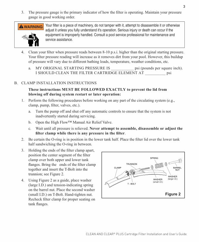
half sandwiching the O -ring in between.3. Holding the ends of the filter clamp apart,
position the center segment of the filter clamp over both upper and lower tank flanges. Bring the ends of the filter clamp together and insert the T-Bolt into the trunnion; see Figure 2.
4. Using Figure 2 as a guide, place washer (large I.D.) and tension-indicating spring on the barrel nut. Place the second washer (small I.D.) on T-Bolt. Hand-tighten nut. Recheck filter clamp for proper seating on tank flanges.
Figure 2
Your filter is a piece of machinery, do not tamper with it, attempt to disassemble it or otherwise adjust it unless you fully understand it's operation. Serious injury or death can occur if the equipment is improperly handled. Consult a pool service professional for maintenance and service assistance.

CLEAN AND CLEAR® PLUS Cartridge Filter Installation and User’s Guide
45. Begin to tighten nut using a 7/8" wrench. Then tap around the outside of the filter clamp with
a mallet (or similar tool) to insure uniform loading and proper seating of the clamp. Continue tapping and tightening until the spring coils touch each other. Do not tighten beyond this point.
6. Follow the procedures in Section C, System Restart Instructions.7. The spring coils should be checked at least once per month to ensure that they continue to touch
each other, indicating that the clamp is under sufficient tension. If coils fail to touch repeat Step B.5 in this section, above.
C. SYSTEM RESTART INSTRUCTIONS
1. Open the High Flow™ Manual Air Relief Valve until it snaps into the full open position (this only requires a quarter turn counter-clockwise). Opening this valve rapidly releases air trapped in the filter.
2. Stand clear of the filter tank, then start the pump. 3. Close the manual air relief valve after a steady stream of water appears.4. The system is not working properly if either of the following conditions occur.
a. A solid stream of water does not appear within 30 seconds after the pump's inlet basket fills with water.
b. The pressure gauge indicates pressure before water outflow appears. If either condition exists, shut off the pump immediately, open valves in the water return line to relieve pressure, and clean the air relief valve, see Section F, Cleaning the manual air relief valve. If the problem persists, call (800) 831-7133 for assistance.
THIS FILTER OPERATES UNDER HIGH PRESSURE. WHEN ANY PART OF THE CIRCULATING SYSTEM (e.g., FILTER LID, PUMP, FILTER, VALVES, ETC.) IS SERVICED, AIR CAN ENTER THE SYSTEM AND BECOME PRESSURIZED. PRESSURIZED AIR CAN CAUSE THE LID TO SEPARATE FROM THE TANK BOTTOM WHICH CAN RESULT IN SEVERE INJURY, DEATH, OR PROPERTY DAMAGE. TO AVOID THIS POTENTIAL HAZARD, FOLLOW THESE INSTRUCTIONS.

CLEAN AND CLEAR® PLUS Cartridge Filter Installation and User’s Guide
5D. CLEANING FILTER MANUALLY
1. Turn the pump off, shut off any automatic controls to ensure that the system is not inadvertently started during servicing.
2. Open the filter High Flow™ Manual Air Relief Valve (and the waste drain valve or plug, if your system has one).
3. Remove hair and lint strainer pot lid and clean basket. Replace basket and secure lid.
4. Disconnect air relief valve drain hose if installed.
5. Release tank clamp assembly and remove tank lid.
6. Remove top manifold and cartridge element separately.
7. Using a garden hose without a nozzle, direct water spray at cartridge element to dislodge and wash away accumulated foreign matter. Flush each cartridge inside and out.
8. Lift bottom manifold out of the tank and flush off any debris.
9. Direct water spray to wash out the inside of the tank body. Water and debris will drain out through the open drain port.
10. Check gasket around outer lip of bottom plate. Gasket must be firmly and evenly set in place. Do not use petroleum base lubricants to avoid damage to the gasket.
11. Place bottom manifold, 4 cartridges, top manifold and air relief tube in place. Make sure the spring and standpipe assembly are retained on the top manifold. Ensure the air relief tube stays in an upright position. This is essential for the maximum air removal from inside the tank.
12. Be certain the O-ring is in position in the lower tank half. Press the filter lid over the lower tank half and sandwich the O -ring in between.
13. Replace tank top and carefully follow instructions in Section B, Clamp Installation Instructions.
14. Replace drain plug and reinstall air relief valve drain hose if used.
Please heed all manufacturers' posted instructions, warnings and cautions when using polyhexamethylene biguanide sanitizers or other cartridge filter cleaner solutions.
Failure to remove all oils and cleaning solutions before acid soaking will result in permanent restriction of water flow through the filter and will cause premature cartridge failure.
The following information should be read carefully since it outlines the proper manner of care and operation for your filter system. As a result of following these instructions and taking the necessary preventative care, you can expect maximum efficiency and life from your filtration system.
Operating the filter system without filter internal components installed can allow air to accumulate within the filter. Pressurized air can cause the lid to blow off which can result in severe injury, death or property damage. Always operate filter system with filter internal components installed.

CLEAN AND CLEAR® PLUS Cartridge Filter Installation and User’s Guide
6E . REPLACING FILTER CARTRIDGES
Filter cartridge element life will vary with pool conditions such as bather load, wind, dust, etc. You can expect an average cartridge life of 3 years under normal conditions.
1. To replace cartridge element follow steps in Section D, Cleaning Filter, eliminating step D.7.
F. CLEANING THE MANUAL AIR RELIEF VALVE
1. Turn the pump off and shut off any automatic controls to ensure that the system is not inadvertently started during servicing.
2. OPEN THE HIGH FLOW™ MANUAL AIR RELIEF VALVE UNTIL IT SNAPS INTO THE FULL OPEN POSITION, THEN WAIT UNTIL ALL PRESSURE IS RELIEVED.
3. With the relief valve attached to the filter tank, pull out the locking tabs and remove the valve stem and cover assembly with a counter-clockwise and lifting motion, see Figure 3.
4. Clean debris from the valve stem and body. Verify that the filter tank's air passage is open by inserting a 5/16" drill bit through the valve body. Verify that the O-rings are in good condition, properly positioned, and lubricated with a silicone base lubricant.
5. Reinstall the valve stem and cover assembly with a downward and clockwise motion until it snaps into position.
SECTION III. TROUBLESHOOTINGA. Air entering your filter is dangerous and can cause the lid to blow off. Correct any conditions in your
filtration system that allow air to enter the system.
1. Some common ways to identify air entering the system:
a. Low water level in pool or spa - skimmer is starving for water with pump running. Add water to pool or spa.
b. Air bubbles or low water level in pump hair and lint pot are caused by: low water level, clogged skimmer basket, split suction cleaner hose, leak in pump hair and lint pot lid, or leak in pump suction line.
c. Air bubbles coming out of water return lines into pool or spa with pump running, see items 1.a and 1.b of this section.
d. Air is discharged from the air relief valve on top of the filter when the valve is opened with the pump running, see items 1.a and 1.b of this section, above.
Figure 3

CLEAN AND CLEAR® PLUS Cartridge Filter Installation and User’s Guide
7B. Until the water initially put into the pool has been completely filtered, short filter cycles in between
cleanings are normal. In most cases pool owners are dismayed by the undesirable color and appearance of water in a newly filled pool. Plaster dust can be responsible for short filter cycles, requiring frequent cleaning.
C. If pressure drops on gauge, check skimmer basket and pump basket first for debris. If the baskets are clean, shut off power to pump and turn off any automatic controls. Then turn motor shaft with your fingers. If it turns freely then the pump must be disassembled and the impeller checked to see if it is clogged. If it is not frozen or clogged then there is an obstruction in the line between the pool and the pump.
D. The pressure gauge is an important part of the filter system. It is your primary indicator of how the system is operating. Maintain your pressure gauge in good working order. Check the operation of your pressure gauge in the following manner:
1. The pressure gauge should go to zero (0) when the system is turned off and pressure is relieved.2. The pressure gauge should indicate pressure when the system is operating.3. The pressure gauge should be readable and not damaged in any way.4. Replace the pressure gauge if it is not meeting the requirements of items D.1 through D.2 of this
section.

CLEAN AND CLEAR® PLUS Cartridge Filter Installation and User’s Guide
8
NOTE: Actual system flow will depend on plumbing size and other system components. * Required Clearance to remove filter elements.
SECTION IV. TECHNICAL DATAA. FLOW RATES
FLOW (gpm)
PRESSURE DROP vs FLOW
PR
ES
SU
RE
DR
OP
(p
si)
0
2
4
6
8
10
12
0 20 40 60 80 100 120 140 160
Clean and Clear® Plus Cartridge FiltersRecommended Flow Rate
Product # Model #Filter Area
sq. ft.Vertical*
ClearanceFlow Rate GPM Turnover Capacity in Gallons
Res. Comm. 6 Hours 8 Hours 12 Hours
160310 CCP240 240 56 in. 90 90 31,400 43,200 64,800
160340 CCP320 320 62 in. 120 120 43,200 57,600 86,400
160301 CCP420 420 68 in. 150 150 54,000 72,000 108,000
160332 CCP520 520 74 in. 150 150 54,000 72,000 108,000
CLEAN AND CLEAR® PLUS Cartridge Filter Installation and User’s Guide
9
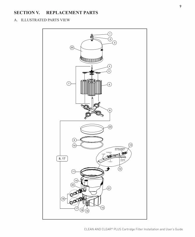
SECTION V. REPLACEMENT PARTSA. ILLUSTRATED PARTS VIEW
11
21
14
1518 19
17
16
22
1
2
3
7
4
5
6
8
9
20
10
8, 17
13
12
23

CLEAN AND CLEAR® PLUS Cartridge Filter Installation and User’s Guide
10
Item Part No. No. Description 1 190058 Gauge, pressure, ¼ in.
2 98209800 High Flow manual air relief valve (HFMARV)
3 98201200 Hose and retainer clips for HFMARV (Optional accy.)
4 56636900 Spring, compression
4 178616 Spring, compression 1 1 1
5 59071000 Manifold, top assy.
5 170026 Manifold, top assy., 240 sq. ft.
5 170027 Manifold, top assy., 320 & 520 sq. ft.
6 R173572 Cartridge Element, 240 sq. ft., 4 req.
6 R173573 Cartridge Element, 320 sq. ft., 4 req.
6 R173574 Cartridge Element, 360 sq. ft., 4 req.
6 R173575 Cartridge Element, 420 sq. ft., 4 req. aqua end caps
6 R173576 Cartridge Element, 420 sq. ft., 4 req.
6 R173577 Cartridge element, 520 sq. ft., 4 req.
6 R173578 Cartridge element, 520 sq. ft., 4 req.
7 170030 Air bleed tube assy., 240 sq. ft.
7 55028500 Air bleed tube assy., 360, 420 sq. ft.
7 170029 Air bleed tube assy., 320 sq. ft.
7 170028 Air bleed tube assy., 420 sq. ft.
7 55028400 Air bleed tube assy., 500 sq. ft.
7 178583 Air bleed tube assy., 520 sq. ft.
8 56626800 Manifold, bottom
8 170035 Manifold, bottom/pipe assy., outlet
8 170040 Manifold, bottom
9 57000300 Gasket, bottom manifold
10 39010200 O-ring, tank clamp (.470 O.D.)
11 190003 Clamp kit, tension control
12 195610 Washer, small I.D.
12a 195611 Washer, large I.D.
13 194997 Nut, machined
B. REPLACEMENT PARTS LIST
Before 11/98 After 11/98 Between 11/98 thru 12/00 After 12/00 After 3/03 After 10/04 Between 11/98 thru 10/04
Item Part No. No. Description 13a 195612 Spring
14 55035000 Baffle, bulkhead assy.
14 190039 Baffle, bulkhead assy.
15 86006900 O-ring, bulkhead, lower
16 98960311 Bulkhead union, (set)
16 271096 Bulkhead adapter kit, 2 in. O.D., white
16 270004 Bulkhead adapter kit, 2 in. O.D., black
16 270100 Bulkhead union kit, 2 in. I.D., black
16 274426 Bulkhead adapter kit, 2 ½ in. x 2 in. I.D., white
17 59019200 Pipe assy., outlet
17 170035 Pipe assy., outlet/manifold, bottom
17 170036 Pipe assy., outlet
18 51005000 O-ring for drain plug
19 86202000 Plug, 1-1/2 in. drain with O-ring
20 170023 Tank, lid assy., 240 sq. ft.
20 170024 Tank, lid assy., 320 sq. ft.
20 178552 Tank, lid assy., 360 sq. ft.
20 178551 Tank, lid assy., 420 sq. ft.
20 178581 Tank, lid assy., 420 sq. ft.
20 178550 Tank, lid assy., 500 sq. ft.
20 178582 Tank, lid assy., 520 sq. ft.
21 178559 Tank, bottom assy.
21 178578 Tank, bottom assy.
22 86006900 O-ring, bulkhead, upper
22 192320 O-ring, bulkhead, upper
23 195339 Ring, back-up
171013 Label kit w/ air relief, 240 sq. ft.
171014 Label Kit w/ air relief, 320, 420, 520 sq. ft.
192019 Drain plug wrench
010126 Filter lid opener tool

NOTES

1620 HAWKINS AVE., SANFORD, NC 27330 • (919) 566-800010951 WEST LOS ANGELES AVE., MOORPARK, CA 93021 • (805) 553-5000 WWW.PENTAIRPOOL.COMAll Pentair trademarks and logos are owned by Pentair or one of its global affiliates. Pentair Aquatic Systems™, Clean and Clear®, High Flow™ and Eco Select® are trademarks and/or registered trademarks of Pentair Water Pool and Spa, Inc. and/or its affiliated companies in the United States and/ or other countries. Unless expressly noted, names and brands of third parties that may be used in this document are not used to indicate an affiliation or endorsement between the owners of these names and brands and Pentair Water Pool and Spa, Inc. Those names and brands may be the trademarks or registered trademarks of those third parties. Because we are continuously improving our products and services, Pentair reserves the right to change specifications without prior notice. Pentair is an equal opportunity employer.© 2015 Pentair Water Pool and Spa, Inc. All rights reserved. This document is subject to change without notice.
178558 REV. N 6/15/15*178558*