cameo data modeler plugin - unified modeling language (uml ... data modeler plugin... · cameo data...
TRANSCRIPT
CAMEO DATA MODELER PLUGIN
18.1
user guide
No Magic, Inc.
2015

All material contained herein is considered proprietary information owned by No Magic, Inc. and is not to be shared, copied, or reproduced by any means. All information copyright 2009-2015 by No Magic, Inc. All Rights Reserved.
C O N T E N T S
3 Copyright © 2009-2015 No Magic, Inc..
GETTING STARTED 6Introduction 6Installing Cameo Data Modeler Plugin 6
ENTITY-RELATIONSHIP (ER) MODELING AND DIAGRAMS 7Introduction 7Basic Concepts 7Business Entity-Relationship Diagrams 8Identifying Relationships and Dependent Entities 9Constraints between Relationships 9Generalization and Specialization 9Key Modeling 13Virtual Entities 13Importing CA ERwin® Data Modeler Projects 14
Importing Data Models 14Imported Elements 15
DATABASE SUPPORT 17Introduction 17SQL Diagrams 17
Crow’s Foot Notation in SQL Diagrams 18Database Modeling 18
Common SQL Element Properties 18Top Level Elements 19
Database 22Schema 22Catalog 22GLOBALS 22
Tables, Columns, and Views 23Persistent Table 24Temporary Table 24View 25Column 26
Modeling Types 27Predefined Type Libraries 27Type Usage 28User Defined Types 29
Sequences and Autoincrement Columns 33Constraints 36
Implicit Primary Key, Unique, Check Constraint, and Index Modeling 37Explicit Primary Key, Unique, Check Constraint, and Index Modeling 39Foreign Keys 40Nullability Constraint 43Assertion 43Triggers 44
Routines 45Procedure 46Function 47Method 47Parameter 47Cursor and Routine Result Table 48
C O N T E N T S
4 Copyright © 2009-2015 No Magic, Inc..
Access Control 49User 49Group 49Role 50Privilege 50Role Authorization 50
Oracle Database Modeling Extensions 51Database Code Engineering 51
Code Engineering Set 52Properties of Code Engineering Set for DDL 53
Supported SQL Statements 55DDL Dialects 57
Standard SQL2 57Oracle 57Cloudscape 58
TRANSFORMATIONS 59Introduction 59UML to SQL Transformation 60
Transformation Procedure 60Conversion of Classes 60Primary Keys Autogeneration 61Sequence Autogeneration 61Conversion of Associations 61Conversion of Identifying Associations 62Conversion of Multivalued Properties 63Conversion of Generalizations 63Conversion of DataTypes 64Conversion of Enumerations 67Package Hierarchy Reorganization 69Naming of Transformed Elements 69Transforming documentation 71Excluding elements from transformation 72
Type Mapping 74UML to SQL Type Map 74
Transformation Properties 76ER to SQL (Generic / Oracle) Transformations 78
Identifying Relationships 78Key Transformation 79Virtual Entity Transformation 79Tracing between Data Model Layers 80
SQL to UML Transformation 80Type Mapping 80Transformation Results 80
UML to XML Schema Transformation 83Type Mapping 84Transformation Results 85
XML Schema to UML Transformation 87Type Mapping 87Transformation Results 87

C O N T E N T S
5 Copyright © 2009-2015 No Magic, Inc..
ENTITY-RELATIONSHIP AND SQL REPORT 89
XML SCHEMAS 92Introduction 92XML Schema Mapping to UML Elements 93
Defined stereotypes 93attribute 95element 97complexType 100attributeGroup 104simpleType 106restriction 106list 106union 107minExclusive 112maxExclusive 113minInclusive 113maxInclusive 114totalDigits 114fractionDigits 115lenght 116minLength 116maxLength 117whiteSpace 117pattern 118enumeration 118unique 119key 120keyref 120selector and field 123
XML representations for the three kinds of identity-constraint definitions 124annotation 125compositors 127group 129any and anyAttribute 130schema 132notation 133redefine 134import 136include 138XML schema namespaces 138

Copyright © 2009-2015 No Magic, Inc.6
GETTING STARTED
IntroductionCameo Data Modeler plugin provides data-related modeling for MagicDraw. It includes entity-relationship, database and XML schema modeling features.
This plugin enables you to draw entity-relationship diagrams (using the crow's foot notation). This is a full-featured variant of ER diagram (including extended entity-relationship concepts - like generalization), providing a spectrum of capabilities for logical data modeling.
This plugin provides SQL database modeling / diagramming and DDL script generation / reverse features. It supports 11 flavors of databases (including Standard SQL, Oracle, DB2, Microsoft SQL Server, MySQL, PostgreSQL), has separate type libraries for them, carries additional modeling extensions for Oracle databases, Transformations from / to plain UML models and from ER models are provided.
This plugin provides XML schema modeling / diagramming and schema file (*.xsd) generation / reversing features. Transformations from / to plain UML models are provided.
Installing Cameo Data Modeler Plugin
To install Cameo Data Modeler plugin
1. From the Help menu, select Resource/Plugin Manager.2. Select Cameo Data Modeler plugin to download and install it.3. Restart MagicDraw to activate Cameo Data Modeler plugin.
Note that when you install the plugin, you get an evaluation key automatically. This key is good for 7 days. Afterwards you need to purchase a license for a plugin to work on diagrams provided by the plugin (when initial license expires, diagrams are switched to the read-only mode).
For more information on how to work with the Resource/Plugin Manager dialog, see MagicDraw User's Manual.pdf.
NOTES • Cameo Data Modeler plugin is a separately purchasable add-on for MagicDraw Standard, Professional, and Architect Editions, and it is free of charge for MagicDraw Enterprise Edition.
• Cameo Data Modeler plugin replaces previous (free) Data Modeling Notations plugin that supported the business entity-relationship diagram, a simplified version of entity-relationship diagram, usable for high level, abstract domain data modeling.
• This plugin repackages database and XML schema modeling functionality, which was previously available only in MagicDraw Architect and Enterprise editions.
Copyright © 2009-2015 No Magic, Inc.7
ENTITY-RELATIONSHIP (ER) MODELING AND DIAGRAMS
IntroductionCameo Data Modeler plugin brings in the following:
• Entity Relationship profile.
• Entity Relationship diagram.
• Template for new ER project creation.
• Sample, demonstrating ER modeling features.
• ER to SQL (Oracle and Generic) transformation and accompanying traceability features.
• Entity-Relationship and SQL report.
Entity-Relationship diagram, as the name suggests, allows specifying entities and relationships between them. It is useful for the abstract domain modeling - to provide structure for data in the domain. It is much more abstract and implementation-independent than the SQL diagram, which shows the concrete implementation of the data structure in the database.
Basic ConceptsAn entity is any thing that is capable of an existence. An entity usually refers to some aspect of the real world, which can be distinguished from other aspects of the real world (a person, place, customer transaction, order...).
An entity is represented by a box shape on the diagram. An entity has two compartments where properties (columns) of the entity can be specified. The upper compartment holds primary key properties of the entity; lower - other properties.
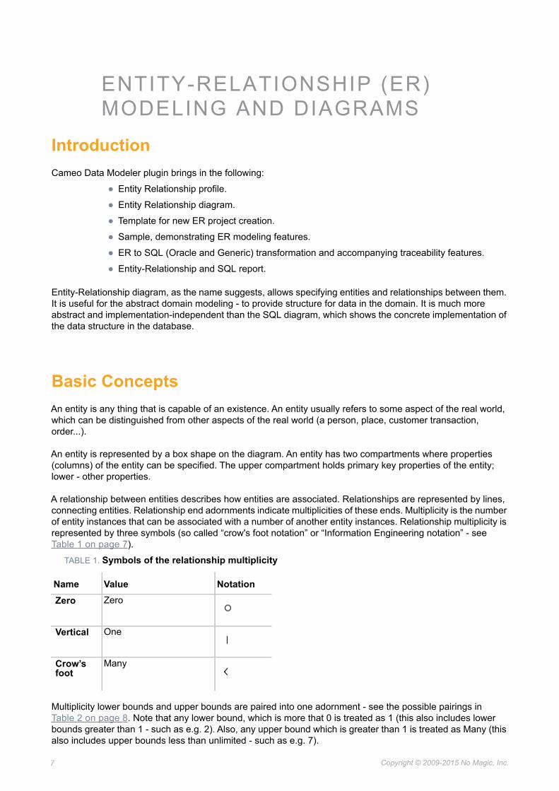
A relationship between entities describes how entities are associated. Relationships are represented by lines, connecting entities. Relationship end adornments indicate multiplicities of these ends. Multiplicity is the number of entity instances that can be associated with a number of another entity instances. Relationship multiplicity is represented by three symbols (so called “crow's foot notation” or “Information Engineering notation” - see Table 1 on page 7).
TABLE 1. Symbols of the relationship multiplicity
Multiplicity lower bounds and upper bounds are paired into one adornment - see the possible pairings in Table 2 on page 8. Note that any lower bound, which is more that 0 is treated as 1 (this also includes lower bounds greater than 1 - such as e.g. 2). Also, any upper bound which is greater than 1 is treated as Many (this also includes upper bounds less than unlimited - such as e.g. 7).
Name Value NotationZero Zero
Vertical One
Crow’s foot
Many
8 Copyright © 2009-2015 No Magic, Inc..
ENTITY-RELATIONSHIP (ER) MODELING AND DIAGRAMSBusiness Entity-Relationship Diagrams
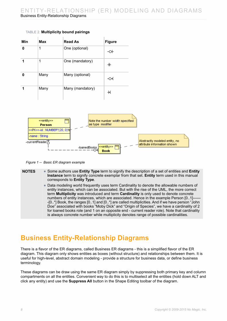
TABLE 2. Multiplicity bound pairings
Figure 1 -- Basic ER diagram example
Business Entity-Relationship DiagramsThere is a flavor of the ER diagrams, called Business ER diagrams - this is a simplified flavor of the ER diagram. This diagram only shows entities as boxes (without structure) and relationships between them. It is useful for high-level, abstract domain modeling - provide a structure for business data, or define business terminology.
These diagrams can be draw using the same ER diagram simply by suppressing both primary key and column compartments on all the entities. Convenient way to do this is to multiselect all the entities (hold down ALT and click any entity) and use the Suppress All button in the Shape Editing toolbar of the diagram.
Min Max Read As Figure0 1 One (optional)
1 1 One (mandatory)
0 Many Many (optional)
1 Many Many (mandatory)
NOTES • Some authors use Entity Type term to signify the description of a set of entities and Entity Instance term to signify concrete exemplar from that set. Entity term used in this manual corresponds to Entity Type.
• Data modeling world frequently uses term Cardinality to denote the allowable numbers of entity instances, which can be associated. But with the rise of the UML, the more correct term Multiplicity was introduced and term Cardinality is only used to denote concrete numbers of entity instances, which are associated. Hence in the example Person [0..1]-------[0..*] Book, the ranges [0..1] and [0..*] are called multiplicities. And if we have person “John Doe” associated with books “Moby Dick” and “Origin of Species”, we have a cardinality of 2 for loaned books role (and 1 on an opposite end - current reader role). Note that cardinality is always concrete number while multiplicity denotes range of possible cardinalities.

9 Copyright © 2009-2015 No Magic, Inc..
ENTITY-RELATIONSHIP (ER) MODELING AND DIAGRAMSIdentifying Relationships and Dependent Entities
Identifying Relationships and Dependent EntitiesOne-to-many (and, very rarely, one-to-one) relationship can be declared identifying. Identifying relationship is a “stronger” version of the relationship, indicating that the one entity (the one at the multiple end of the relationship) can not exist without the entity on the other end.
You can create such relationships using buttons on a diagram pallet. You can also turn an existing relationship into identifying and back again. For this you can choose to do one of the following: either change the Is Identifying property value in the relationship Specification window or select the appropriate check box on its shortcut menu.
Identifying relationship is drawn as solid line. Non-identifying relationships use heavy dashes.
Closely related concept is dependent / independent entities. Dependent entities are those, which are at the multiple end of the identifying relationship. They cannot exist without the independent entity at the other end. In addition every inherited entity (if you are doing EER modeling) is considered to be dependent.
Dependent entity's primary key includes the other entity's key as part (this is implied, not shown in the model).
Dependent entities are automatically recognized and drawn with rounded corners.
Figure 2 -- Example of identifying relationship and dependent entity in ER diagram
Constraints between RelationshipsYou can place XOR constraints (there is also a rarely used OR constraint) between relationships using a corresponding toolbar button. Note that constraint must join relationships, that have at least one common end - not any arbitrary relationships.
Current implementation of constraints does not allow placing a constraint on more than 2 relationships.
Generalization and SpecializationER diagram has a support for generalization / specialization modeling. Generalization and Specialization is really the same relationship, just the different direction of classification (generalization is bottom-up, specialization is top-down). Hence they use the same model element.

10 Copyright © 2009-2015 No Magic, Inc..
ENTITY-RELATIONSHIP (ER) MODELING AND DIAGRAMSGeneralization and Specialization
Generalizations can be joined into generalization sets (trees of generalizations), which allow specifying additional properties on a group of generalizations - such as disjointness and completeness constraints.
Figure 3 -- Example of generalization in ER diagram
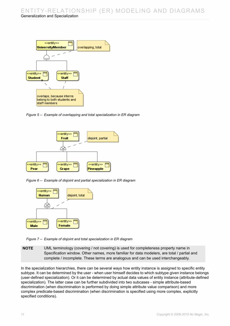
Disjointness and completeness constraints are specified using the Is Disjoint (true for disjoint, false for overlapping specialization) and Is Covering (true for total, false for partial specialization) properties. They can be set via the relationship shortcut menu or in the Specification window.
Hence there are 4 combinations of these two settings. The “breadloaf” symbol joining generalizations into a tree shows these 4 variations - see the following figures.
Figure 4 -- Example of overlapping and partial specialization in ER diagram
11 Copyright © 2009-2015 No Magic, Inc..
ENTITY-RELATIONSHIP (ER) MODELING AND DIAGRAMSGeneralization and Specialization
Figure 5 -- Example of overlapping and total specialization in ER diagram
Figure 6 -- Example of disjoint and partial specialization in ER diagram
Figure 7 -- Example of disjoint and total specialization in ER diagram
In the specialization hierarchies, there can be several ways how entity instance is assigned to specific entity subtype. It can be determined by the user - when user himself decides to which subtype given instance belongs (user-defined specialization). Or it can be determined by actual data values of entity instance (attribute-defined specialization). The latter case can be further subdivided into two subcases - simple attribute-based discrimination (when discrimination is performed by doing simple attribute value comparison) and more complex predicate-based discrimination (when discrimination is specified using more complex, explicitly specified conditions).
NOTE UML terminology (covering / not covering) is used for completeness property name in Specification window. Other names, more familiar for data modelers, are total / partial and complete / incomplete. These terms are analogous and can be used interchangeably.

12 Copyright © 2009-2015 No Magic, Inc..
ENTITY-RELATIONSHIP (ER) MODELING AND DIAGRAMSGeneralization and Specialization
Examples of these two cases are shown in the following figures.
Figure 8 -- Example of attribute-based discriminator in ER diagram
Figure 9 -- Example of predicate-based discriminator in ER diagram
Discriminators are modeled as special constraints, placed on individual generalization relationships. The easiest way to access them is from the shortcut menu of the generalization.
Predicate-based discriminator is simpler - you just fill in the Specification field of the predicate with an appropriate expression text.
Attribute-based discriminator is more complex. First you have to specify columns, by which you will discriminate the entities into the corresponding subclasses. This is done by filling in the Discriminator field of the generalization set (you can specify one or several columns there). Then you have to fill in the Template field of the predicate. This template field holds an instance specification, which is used as template or etalon to differentiate the entity instances into appropriate subclasses. Fill in the slots for the same columns that you indicated on the generalization set.
NOTE Category (also know as union) concept is currently not explicitly sup-ported. Total (but not partial) categories can be “simulated” using the total specialization tree, just visually reversed.
13 Copyright © 2009-2015 No Magic, Inc..
ENTITY-RELATIONSHIP (ER) MODELING AND DIAGRAMSKey Modeling
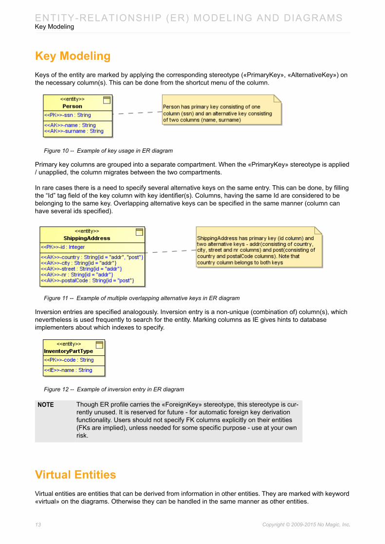
Key ModelingKeys of the entity are marked by applying the corresponding stereotype («PrimaryKey», «AlternativeKey») on the necessary column(s). This can be done from the shortcut menu of the column.
Figure 10 -- Example of key usage in ER diagram
Primary key columns are grouped into a separate compartment. When the «PrimaryKey» stereotype is applied / unapplied, the column migrates between the two compartments.
In rare cases there is a need to specify several alternative keys on the same entry. This can be done, by filling the “Id” tag field of the key column with key identifier(s). Columns, having the same Id are considered to be belonging to the same key. Overlapping alternative keys can be specified in the same manner (column can have several ids specified).
Figure 11 -- Example of multiple overlapping alternative keys in ER diagram
Inversion entries are specified analogously. Inversion entry is a non-unique (combination of) column(s), which nevertheless is used frequently to search for the entity. Marking columns as IE gives hints to database implementers about which indexes to specify.
Figure 12 -- Example of inversion entry in ER diagram
Virtual EntitiesVirtual entities are entities that can be derived from information in other entities. They are marked with keyword «virtual» on the diagrams. Otherwise they can be handled in the same manner as other entities.
NOTE Though ER profile carries the «ForeignKey» stereotype, this stereotype is cur-rently unused. It is reserved for future - for automatic foreign key derivation functionality. Users should not specify FK columns explicitly on their entities (FKs are implied), unless needed for some specific purpose - use at your own risk.
14 Copyright © 2009-2015 No Magic, Inc..
ENTITY-RELATIONSHIP (ER) MODELING AND DIAGRAMSImporting CA ERwin® Data Modeler Projects
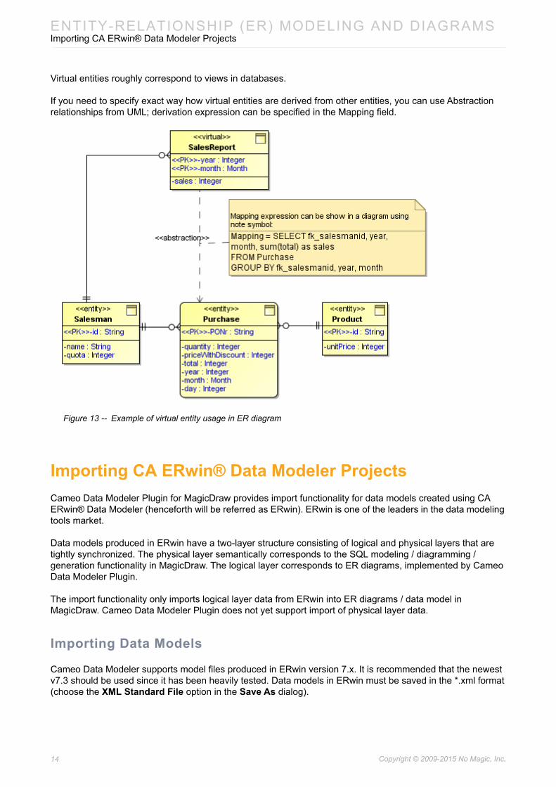
Virtual entities roughly correspond to views in databases.
If you need to specify exact way how virtual entities are derived from other entities, you can use Abstraction relationships from UML; derivation expression can be specified in the Mapping field.
Figure 13 -- Example of virtual entity usage in ER diagram
Importing CA ERwin® Data Modeler ProjectsCameo Data Modeler Plugin for MagicDraw provides import functionality for data models created using CA ERwin® Data Modeler (henceforth will be referred as ERwin). ERwin is one of the leaders in the data modeling tools market.
Data models produced in ERwin have a two-layer structure consisting of logical and physical layers that are tightly synchronized. The physical layer semantically corresponds to the SQL modeling / diagramming / generation functionality in MagicDraw. The logical layer corresponds to ER diagrams, implemented by Cameo Data Modeler Plugin.
The import functionality only imports logical layer data from ERwin into ER diagrams / data model in MagicDraw. Cameo Data Modeler Plugin does not yet support import of physical layer data.
Importing Data Models
Cameo Data Modeler supports model files produced in ERwin version 7.x. It is recommended that the newest v7.3 should be used since it has been heavily tested. Data models in ERwin must be saved in the *.xml format (choose the XML Standard File option in the Save As dialog).

15 Copyright © 2009-2015 No Magic, Inc..
ENTITY-RELATIONSHIP (ER) MODELING AND DIAGRAMSImporting CA ERwin® Data Modeler Projects
To import an ERwin model
1. Start MagicDraw.2. Click File > Import From > CA ERwin Data Modeler v7.x. The Open file dialog will open.3. Select an ERwin model file (*.xml). A new MagicDraw project will be created and logical model
will be imported from the ERwin model file into that project.
After successful import, you can proceed to edit or manage the model using MagicDraw features.
If you want to include the ER model as part of a larger project in MagicDraw, you can use either module linking functionality (click File > Use Module) to attach the ER model to your main project model or project import functionality (click File > Import From > Another MagicDraw Project) to transfer the contents of this ER model to your main project model.
If you want to update an imported and edited ER model, for example, you have made changes to the ERwin model and want to import those changes into MagicDraw again, you can use the merge functionality (click Tools > Project Merge) to import the ERwin model into a new ER model and merge it with the model you have imported earlier.
Imported ElementsTABLE 3. Import Mapping Reviews and Notes
ERwin Cameo Data Modeler
Comments
Any element Any Element • For each element, it’s name, definition, and notes are imported.
• Definitions are imported as MagicDraw documentation (special UML comments) and notes are imported as UML comments.
Entity Entity
Attribute Attribute • The Null / Not Null setting is imported as UML multiplicities [0..1] / [1].
• Attribute constraints and default value information is imported.
• Domain information is not imported because domains are not supported.
• Attribute type information is imported - the standard primitive types are mapped to the UML primitive types.
• Other types (which are not found in the model) are created on the fly.
Key Key Marking on Attributes
• There is no separate standalone model element for a key in the Cameo Data Modeler ER diagrams. Instead, attributes belonging to a key are marked by applying a stereotype to them (PK, AK, or IE) as necessary.
Relationship Association relationship
• Simple relationships are mapped to UML associations.• Verb phrases are mapped to role names.• Cardinality and null / not null settings are mapped to
UML multiplicities ([0..1], [1], [0..*], [1..*]).• Referential integrity information is stored in a special
stereotype / tag.• Key information is not imported since the current ER
diagrams do not support FK modeling.
16 Copyright © 2009-2015 No Magic, Inc..
ENTITY-RELATIONSHIP (ER) MODELING AND DIAGRAMSImporting CA ERwin® Data Modeler Projects
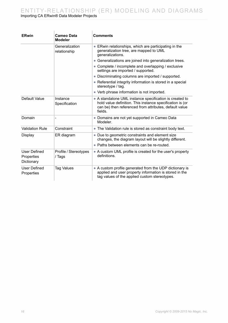
Generalization relationship
• ERwin relationships, which are participating in the generalization tree, are mapped to UML generalizations.
• Generalizations are joined into generalization trees.• Complete / incomplete and overlapping / exclusive
settings are imported / supported.• Discriminating columns are imported / supported.• Referential integrity information is stored in a special
stereotype / tag.• Verb phrase information is not imported.
Default Value Instance Specification
• A standalone UML instance specification is created to hold value definition. This instance specification is (or can be) then referenced from attributes, default value fields.
Domain - • Domains are not yet supported in Cameo Data Modeler.
Validation Rule Constraint • The Validation rule is stored as constraint body text.
Display ER diagram • Due to geometric constraints and element size changes, the diagram layout will be slightly different.
• Paths between elements can be re-routed.
User Defined Properties Dictionary
Profile / Stereotypes / Tags
• A custom UML profile is created for the user's property definitions.
User Defined Properties
Tag Values • A custom profile generated from the UDP dictionary is applied and user property information is stored in the tag values of the applied custom stereotypes.
ERwin Cameo Data Modeler
Comments

Copyright © 2009-2015 No Magic, Inc.17
DATABASE SUPPORT
IntroductionCameo Data Modeler plugin brings the following:
• IMM Relational profile for SQL modeling support (the profile is named according to the OMG working group name).
• Extension profile for Oracle.
• SQL diagram, Oracle SQL diagram and customizations for profile.
• Code engineering (generation / reverse) features for working with database generation scripts.
• Primitive type libraries for database flavors.
• Template for new Database project creation.
• Sample, demonstrating database modeling features.
• UML / ER to SQL (Oracle and generic) and SQL to UML transformations and accompanying traceability features.
• Entity-Relationship and SQL report.
• Helper functionality for SQL diagrams - notation switch.
Cameo Data Modeler plugin provides support for database modeling and code engineering. It supports modeling of the database concepts at the level of SQL:1999 (SQL3) standard. A few rarely used concepts (like collation, translation) are not supported.
SQL DiagramsCameo Data Modeler provides a specialized diagram for database modeling. This diagram is called SQL Diagram and is located under Data Modeling diagram subgroup. This diagram provides means for creating and depicting various SQL elements.
In addition to the main SQL diagram, there is a slightly modified diagram for Oracle databases. It is called Oracle SQL Diagram and is located under the same Data Modeling diagram subgroup. This diagram is only slightly modified - it has an additional diagram button for the Materialized View modeling. Otherwise than that, it is identical to the main SQL diagram. If you are not modeling materialized views, you can freely use the generic diagram type instead of specialized one for Oracle modeling.
IMPORTANT! A BIG DISCLAIMER UPFRONT. In v17.0.1 SQL modeling was significantly extended and reworked. The new profile for SQL modeling covers more SQL concepts than the old Generic DDL and Oracle DDL profiles, that were previously used for SQL modeling. How-ever the code engineering features (script generation and reverse engineering) were not upgraded yet - code engineering capabilities are almost the same as in v17.0. There is cur-rently a skew between the modeling and code engineering features. Some things that can be modeled with the help of the current profile can not yet be not generated / reversed to / from database script.

18 Copyright © 2009-2015 No Magic, Inc..
DATABASE SUPPORTDatabase Modeling
Crow’s Foot Notation in SQL Diagrams
Once Cameo Data Modeler plugin is applied to MagicDraw you can display the crow’s foot notation or use standard UML notation of associations (displaying multiplicities in text format) in the SQL diagram.
To display Multiplicities or crow’s foot notation in a SQL diagram
1. Create the SQL diagram.2. Draw two tables.3. Create columns for the tables and some of them as primary keys.4. Connect the table elements with the Foreign Key relationship.5. Define Name, PK, and FK in the open Foreign Key dialog box.6. Open the Project Options dialog box.7. Select the General project options branch.8. Change the Show relationship ends as property correspondingly to either No special
notation or Crow’s feet. Multiplicities (Figure 14 on page 18) or crow’s foot notation (Figure 15 on page 18) will then be displayed on the Foreign Key ends.
Figure 14 -- Multiplicities on Foreign Key relationship in SQL diagram
Figure 15 -- Crow’s foot notation for Foreign Key relationship in SQL diagram
Database ModelingThis chapter covers modeling of various SQL elements - in detail and with examples.
Common SQL Element Properties
These properties are common and available for all SQL model elements in their Specification windows.
Property name DescriptionName Name of this SQL model element.
Label Label of SQL model element. Can be used for various referring purposes (both human and code referral).
Description Longer text, describing this SQL element in more detail.

19 Copyright © 2009-2015 No Magic, Inc..
DATABASE SUPPORTDatabase Modeling
In addition to these SQL properties, some common, useful UML model properties are shown in the Specification windows (only in the Expert mode).
Top Level Elements
There are several top-level model elements, that serve as the containers for other model elements of the database model. Those are: Database, Schema, Catalog.
Top level elements are not strictly necessary to begin database modeling. You can start modeling database elements (like tables) in the standard UML package (even directly under root ‘Data’ model element). But top level elements help to provide context for those other elements and their naming and positioning in the database. So, at least one top level element should be present - either Schema element or Database element. Optimally both Database and Schema element should be present in the model (Schema package inside the Database package). Catalog modeling is less important, it can be skipped. Not all databases have support for catalogs.
TODO Additional remarks about the further modifications, necessary for this element
Property name FunctionQualified Name Fully qualified name of this model element - names of all owning parent
elements and this element, concatenated using “::” separators.
Owner Model element, directly owning this element.
Applied Stereotype
Stereotypes, applied on this model element, extending element data over and above the standard UML functionality. SQL extension stereotypes can be seen here (implementing SQL model features, described in this document) as well as any additional extensions.
Image Custom image can be set on each model element if necessary.
Property name Description

20 Copyright © 2009-2015 No Magic, Inc..
DATABASE SUPPORTDatabase Modeling
When top-level element is created (either on the diagram or in the containment tree), a special dialog is shown for selecting database flavor.
Figure 16 -- Database flavor selection dialog
When DB flavor is chosen, the necessary profile for that DB flavor is attached to the project (providing standard data types for that DBMS and / or additional stereotypes for modeling extensions of that DB flavor). Then profile application relationship is created from the package that is being created (Database, Schema) to the attached DB profile. This marks the top level element as belonging to this DB flavor, Other DB elements, created under that top level element will be automatically considered as belonging to this DB flavor.
If you would like to switch database flavor after creating a top level element, you can do this in the following way.
To switch database flavor after creating a top level element
1. Right-click the top level element.2. From the shortcut menu, select Apply Profiles.3. Select the check box near the needed profile and clear the check box near the old profile.4. Click Apply.
IMPORTANT! You must have the necessary module attached to your project (use File>Use Module menu, choose the necessary module from your <install.root>\profiles predefined loca-tion)

21 Copyright © 2009-2015 No Magic, Inc..
DATABASE SUPPORTDatabase Modeling
Top level elements can be explicitly drawn, on the diagram.
Figure 17 -- Database top level containers (Database and Schema) on diagram pane
However, showing top level elements on the diagram, and nesting their contents inside them is often clumsy, and consumes valuable diagram space. Showing them on the diagram pane is not necessary; it is enough to create them in the Containment tree (using the New Element command on the shortcut menu). Then, place your diagram inside the created containers, and the elements that you will be creating in your diagram, will go into the necessary container. See the following figure (logically equivalent to the previous one), showing a top level element just in the Containment tree and not displayed on the diagram pane.
Figure 18 -- Database top level containers (Database and Schema) in Containment tree, but not on diagram pane
There is also one additional complication, steming from the limitations of UML. UML does not allow placing UML properties (which are used for SQL sequence modeling), or operations (which are used for SQL stored procedure & function modeling) directly into packages. Properties and operations can only occur in classes. A special model element was introduced to work around this limitation - GLOBALS element (based on UML class). This intermediate element can be placed directly inside the top level element (usually Schema, but can
22 Copyright © 2009-2015 No Magic, Inc..
DATABASE SUPPORTDatabase Modeling
also be placed under Database) and then the necessary database elements - sequences, stored procedures can be placed inside it.
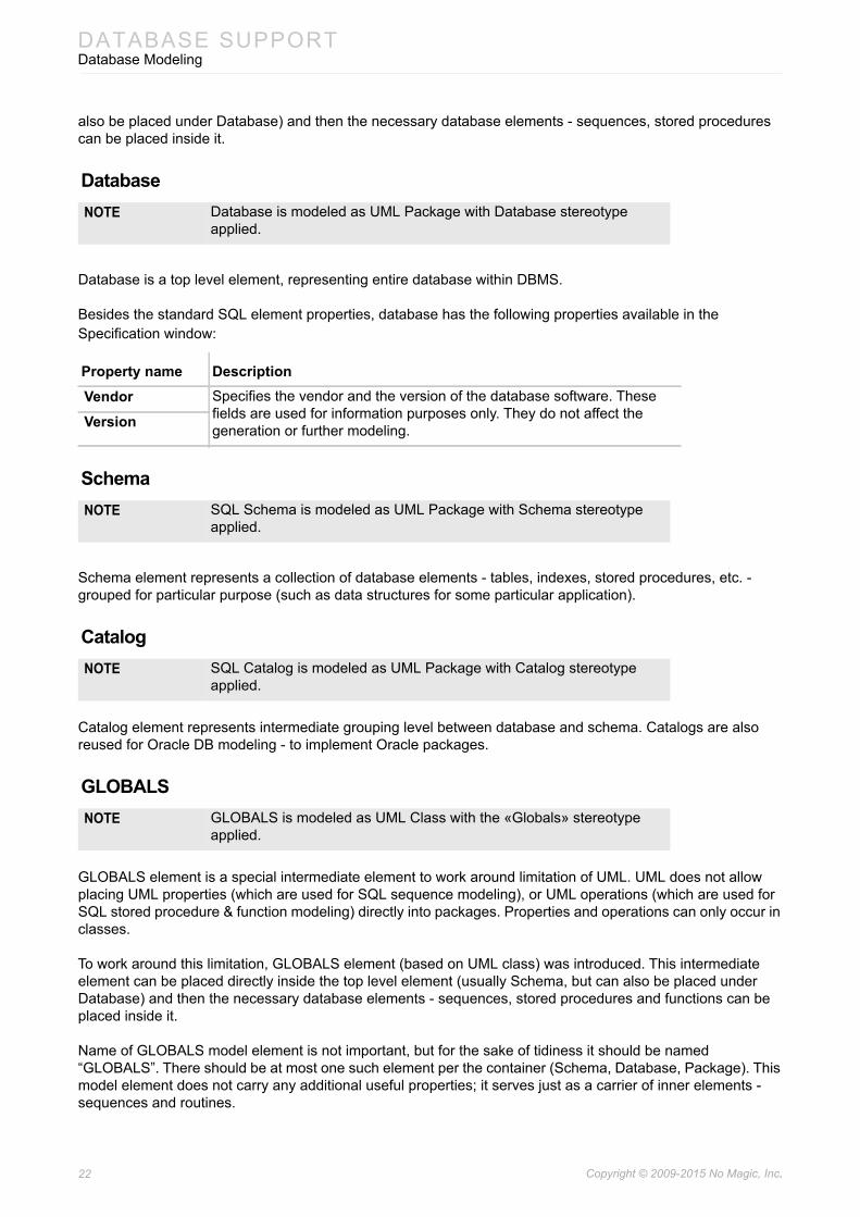
Database
Database is a top level element, representing entire database within DBMS.
Besides the standard SQL element properties, database has the following properties available in the Specification window:
Schema
Schema element represents a collection of database elements - tables, indexes, stored procedures, etc. - grouped for particular purpose (such as data structures for some particular application).
Catalog
Catalog element represents intermediate grouping level between database and schema. Catalogs are also reused for Oracle DB modeling - to implement Oracle packages.
GLOBALS
GLOBALS element is a special intermediate element to work around limitation of UML. UML does not allow placing UML properties (which are used for SQL sequence modeling), or UML operations (which are used for SQL stored procedure & function modeling) directly into packages. Properties and operations can only occur in classes.
To work around this limitation, GLOBALS element (based on UML class) was introduced. This intermediate element can be placed directly inside the top level element (usually Schema, but can also be placed under Database) and then the necessary database elements - sequences, stored procedures and functions can be placed inside it.
Name of GLOBALS model element is not important, but for the sake of tidiness it should be named “GLOBALS”. There should be at most one such element per the container (Schema, Database, Package). This model element does not carry any additional useful properties; it serves just as a carrier of inner elements - sequences and routines.
NOTE Database is modeled as UML Package with Database stereotype applied.
Property name DescriptionVendor Specifies the vendor and the version of the database software. These
fields are used for information purposes only. They do not affect the generation or further modeling.Version
NOTE SQL Schema is modeled as UML Package with Schema stereotype applied.
NOTE SQL Catalog is modeled as UML Package with Catalog stereotype applied.
NOTE GLOBALS is modeled as UML Class with the «Globals» stereotype applied.

23 Copyright © 2009-2015 No Magic, Inc..
DATABASE SUPPORTDatabase Modeling
Tables, Columns, and Views
Tables and their constituent columns are the main elements for describing database data structures. Table stores multiple rows of data each consisting of several columns. Each cell holds one data value (or is empty). All values of one column are of the same type. Correspondingly each table description consists of the table name and a set of column descriptions. Additionally there are various kinds of constraints (including the all-important primary key and foreign key constraints), that can be applied on tables and triggers, specifying additional actions to be performed during data manipulation.
See “Constraints” on page 36 for constraints and “Triggers” on page 44 for triggers.
There can be various kinds of tables
• Normal persistent tables
• Temporary tables
• Views (derived tables)
The following figure illustrates various kinds of tables that can be modeled on the diagram.
Figure 19 -- Various kinds of tables: persistent tables, temporary tables, and views
Tables can have generalization relationships between them. These relationships correspond to the following SQL syntax in the create table statement:
CREATE TABLE <name> OF <UDT name> [UNDER <supertable>]
There can be at most 1 outgoing generalization. Generalizations are not widely supported in database management systems. As of v17.0.1 Cameo Data Modeler supports modeling of these structures. Generation of corresponding script code is not supported yet.

24 Copyright © 2009-2015 No Magic, Inc..
DATABASE SUPPORTDatabase Modeling
Persistent Table
Persistent table is the most often used kind of table.
Besides the standard SQL element properties, persistent table has the following properties available in the Specification window (these properties are only available in Expert mode).
Temporary Table
Temporary table is a kind of table, where data is held only temporary. There are two kinds of temporary tables. Local temporary table persists for the duration of user session and is visible only for the creator user. Global temporary table is long lived and visible for all users. Note that data in the global temporary table is different for different users and does not persist throughout user sessions (only global table definition persists).
Temporary tables are created using SQL create table statement (using TEMPORARY option):
CREATE (GLOBAL | LOCAL) TEMPORARY TABLE <table name> ...[ON COMMIT (PRESERVE | DELETE) ROWS]
Besides the standard SQL element properties and persistent table properties (see section above), temporary table has the following properties available in the Specification window.
NOTE SQL Persistent Table is modeled as UML Class with the «Persistent-Table» stereotype applied. For the sake of compactness, these tables are displayed with the «table» keyword (instead of the long form - «PersistentTable») on the diagram.
Property name DescriptionUser-defined type
Points to structured user defined type, which serves as a base for the row type of the table.
Supertable Points to the parent (base) table. Can only be used together with user-defined type.
Self Ref Column Generation
Describes the self-referencing column generation options. Can only be used together with user-defined type. Corresponds to the following subclause of SQL create table statement:REF IS <column name> [SYSTEM GENERATED|USER GENERATED|DERIVED]
Referencing Foreign Keys
This is back reference from foreign keys, referencing this table. This field is for information purposes only. If you want to change it, change Referenced Table field of the foreign key instead.
Insertable These are two derived (non editable) fields, describing table data editing capabilities. At the moment calculation of these properties is not implemented - they are always set to falseUpdatable
NOTE SQL Temporary Table is modeled as UML Class with the «Temporar-yTable» stereotype applied. For the sake of compactness, these tables are displayed with the «temporary» keyword (instead of the long form - «TemporaryTable») on the diagram.
Property name DescriptionLocal Marks the table as local or global temporary table.
Delete On Commit
Regulates whether data is deleted or retained on commit.

25 Copyright © 2009-2015 No Magic, Inc..
DATABASE SUPPORTDatabase Modeling
View
View is a table, whose data is derived from data of other tables (by applying some SQL query).
Views are created using SQL create view statement:
CREATE VIEW <name> [<view column list>]AS <query expression>[ WITH [ CASCADED | LOCAL ] CHECK OPTION ]
Note that since column definition list is optional in SQL syntax, specifying column definitions in the view is also optional (columns can be inferred from query expression of the view). However it is often a good idea to include column definitions, since this allows to see view data structure on the diagram / in the model at a glance, without parsing the query expression text.
Besides the standard SQL element properties and persistent table properties (see section above), view has the following properties available in the Specification window
Query expression of the view modeling deserves a special attention. Query expression, defining the view, is not just a simple string, but a (stereotyped) UML model element. By default query expression model object is stored within the view definition itself. There is a special constraint, automatically created inside the view, to hold this expression. When the view is created, Query Expression field (which is a tag of stereotype, applied on the view) is automatically pointed to this expression.
So by default you just need to fill in the Body text of the expression. To do that you need to double-click on the Query Expression field. This opens Specification window for the expression itself, where Body can be filled in. This is the default, no-hassle way to specify view. It is easy. But it has one deficiency. Views created this way do not have any model references to the underlying table model elements. This may be undesirable from the dependency tracking standpoint (in the dependency analysis). To remedy this, you can draw an additional Dependency relationships between the view and base tables.
There is also another way to model the query expression, defining the view. If you click on the ... button of the Query Expression field, this action opens the element selection dialog, allowing to retarget the Query Expression pointer choose another expression object, located somewhere else in the model. For example view definition expression can be located inside the Abstraction relationship, drawn from the view to the base table (Mapping field of the Abstraction).
To model view queries using abstractions
1. Draw an abstraction relationship between a View and a Table.2. In the abstraction’s Specification window, fill in the Mapping cell. This will be an inner UML
OpaqueExpression model element with language and body cells. Set language to “SQL” and fill in the body with the necessary “SELECT ...” expression text.
3. Further open the Specification window of the mapping expression, and apply the «QueryExpressionDefault» stereotype.
NOTE SQL View is modeled as UML Class with the «ViewTable» stereotype applied. For the sake of compactness, views are displayed with the «view» keyword (instead of the long form - «ViewTable») on the dia-gram.
Property name DescriptionQuery Expression
A query expression, defining how data is calculated / retrieved for this view. This is an SQL SELECT statement.
Check Type Describes how check is performed on the data update through the view. Only meaningful for updateable views (which is rare).

26 Copyright © 2009-2015 No Magic, Inc..
DATABASE SUPPORTDatabase Modeling
4. Open the Specification window of the view. Click the ... button in the Query Expression cell. In the element Selection dialog navigate to the abstraction relationship and select the expression inside of it.
This way to model view query expressions is rather tedious - so it is not recommended for modeling novices. But it has an advantage of capturing the real relationship in the model between the view and the constituent table(s). Also query expression can be shown on the abstraction relationship (using note mechanism) instead of showing expression on the view.
In the following figure you can see a diagram that illustrates the alternative way of view modeling.
Figure 20 -- Alternative notation for modeling view derivation from tables
Column
Column model element describes one column of the table. In the most frequent case it’s just a name of the column and a type. Additionally column can carry default value specification, column constraints.
Column definition syntax in SQL (in CREATE TABLE, ADD COLUMN statements):
<column name> [ <data type> ][ DEFAULT <value expression> | GENERATED { ALWAYS | BY DEFAULT } AS IDENTITY
[ ‘(‘ <sequence options> ‘)’ ] | GENERATED ALWAYS AS <expression>][ <column constraint definition>... ]
NOTE SQL Column is modeled as UML Property with «Column» stereotype applied. For the sake of compactness, columns are displayed with the «col» keyword (instead of the long form - «Column») on the diagram.
27 Copyright © 2009-2015 No Magic, Inc..
DATABASE SUPPORTDatabase Modeling
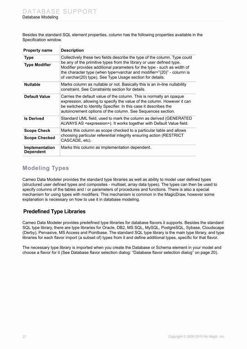
Besides the standard SQL element properties, column has the following properties available in the Specification window.
Modeling Types
Cameo Data Modeler provides the standard type libraries as well as ability to model user defined types (structured user defined types and composites - multiset, array data types). The types can then be used to specify columns of the tables and / or parameters of procedures and functions. There is also a special mechanism for using types with modifiers. This mechanism is common in the MagicDraw, however some explanation is necessary on how to use it in database modeling.
Predefined Type Libraries
Cameo Data Modeler provides predefined type libraries for database flavors it supports. Besides the standard SQL type library, there are type libraries for Oracle, DB2, MS SQL, MySQL, PostgreSQL, Sybase, Cloudscape (Derby), Pervasive, MS Access and Pointbase. The standard SQL type library is the main type library, and type libraries for each flavor import (a subset of) types from it and define additional types, specific for that flavor.
The necessary type library is imported when you create the Database or Schema element in your model and choose a flavor for it (See Database flavor selection dialog: “Database flavor selection dialog” on page 20).
Property name DescriptionType Collectively these two fields describe the type of the column. Type could
be any of the primitive types from the library or user defined type. Modifier provides additional parameters for the type - such as width of the character type (when type=varchar and modifier=”(20)” - column is of varchar(20) type). See Type Usage section for details.
Type Modifier
Nullable Marks column as nullable or not. Basically this is an in-line nullability constraint. See Constraints section for details.
Default Value Carries the default value of the column. This is normally an opaque expression, allowing to specify the value of the column. However it can be switched to Identity Specifier. In this case it describes the autoincrement options of the column. See Sequences section.
Is Derived Standard UML field, used to mark the column as derived (GENERATED ALWAYS AS <expression>). It works together with Default Value field.
Scope Check Marks this column as scope checked to a particular table and allows choosing particular referential integrity ensuring action (RESTRICT CASCADE, etc).Scope Checked
Implementation Dependent
Marks this column as implementation dependent.

28 Copyright © 2009-2015 No Magic, Inc..
DATABASE SUPPORTDatabase Modeling
Type Usage
Figure 21 -- Type specifying. Library type and modifier vs. separately modeled type
Usage of a simple SQL type, such as boolean, is very simple. If you want to set it as a type of a column or operation parameter, you just need to specify it in the type field. However there are types (such as varchar or numeric) in SQL, which require additional data. There are two mechanisms to specify these kinds of types: either use the library type+ type modifier mechanism or create your own type element.
Lets take the standard varchar type as an example. It must have the maximum length data provided at each usage. Semantically there are many different types, one for each length limit - varchar(20), varchar(53), varchar(255) etc. Now the standard type library can not provide myriad of different varchar types. Library only provides the varchar type definition.
To specify that column is of varchar(20)
1. Set the type field of the column to varchar type from the library.2. Set the type modifier field of the column to “(20)” (no quotes). Note that type modifier is a
simple string - whatever is entered in this field, will be used in script generation verbatim, without additional checks. An example of more complex type modifier would be “(10, 2)” type modifier for numeric data type.
Alternative way to specify that column is of varchar(20) is to explicitly create a separate type in the model.
29 Copyright © 2009-2015 No Magic, Inc..
DATABASE SUPPORTDatabase Modeling
To specify that column is of varchar(20) in the alternative way
1. Create the necessary type (use one of the buttons in the SQL diagram, Primitive Types toolbar) - character string, fixed precision, integer, approximate, boolean, binary, date or XML types. In our case this would be character string type.
2. Set the length data in the dedicated tag (look up the length tag in the Tags section of the Specification window). Note that this is numeric field - you need to input number 20, and not the “(20)” string as was the case with type modifiers.
3. The name of your type can be whatever you like. For example varchar_of_20. The name is not important.
4. Inherit (draw generalization relationship) your type from the appropriate type from the type library. In this case, inherit varchar_of_20 from varchar form the library. This information will be used for determining the proper type name during script generation (so, in the generated script you will see the proper type reference - varchar(20)).
5. This created type can now be specified in the type field of the column(s).
There would be one type in the model for each varchar length that you use in your database.
The second way is more tedious - you need to create quite a few types. So by default the first way is used. But the second way has several advantages, that may outweight it’s deficiencies. First - there is one spot where parameters of the type can be changed. You can easily widen the varchar(20) fields to varchar(40) by editing just one place in the model. Secondly, you can define some additional parameters of the type - such as character set.
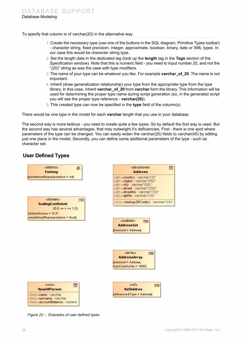
User Defined Types
Figure 22 -- Examples of user defined types

30 Copyright © 2009-2015 No Magic, Inc..
DATABASE SUPPORTDatabase Modeling
Besides the primitive / built-in types of the database, user can define additional types for his own schema.
Distinct Type
Distinct type definition allows to redefine some primitive type in order to enforce the non-assignability rules. For example, two distinct types Meters and Yards can be defined on the base primitive type float. With this definition, system would enforce checks that yard fields / columns are not assigned to meter fields / columns without a conversion (explicit cast).
Besides the standard SQL element properties, distinct type has the following properties available in the Specification window.
Domain
Domain allows to define a more narrow set of values than the base primitive type allows. This narrowing is done by assigning additional constraints on the domain. Columns, whose types are set to the domain, can only assume values from this more narrow subset.
Besides the standard SQL element properties, domain has the following properties available in the Specification window.
Structured User Defined Type
Structured UDT defines a composite datatype. Each value of this type is a tuple of several values; each position in a tuple has a name. Structured UDT value is analogous to one row of the table. Structured UDTs allow single inheritance (multiple inheritance is not supported). Inheritance (subtype-supertype relationship) can be modeled using UML Generalization relationships
NOTE SQL Distinct type is modeled as UML DataType with «DistinctUserDe-finedType» stereotype applied. For the sake of compactness, refer-ences are displayed with the «distinct» keyword (instead of the long form - «DistinctUserDefinedType») on the diagram.
Property name DescriptionPredefined Representation
Points to some base primitive type.
NOTE SQL Domain is modeled as UML DataType with «Domain» stereotype applied. For the sake of compactness, domains are displayed with the «domain» keyword on the diagram.
Property name DescriptionPredefined Representation
Points to some base primitive type.
Default Value Default value for the column if no value is specified.
NOTE SQL Structured User Defined Type is modeled as UML DataType with «StructuredUserDefinedType» stereotype applied. For the sake of com-pactness, domains are displayed with the «structured» keyword (instead of the long form - «StructuredUserDefinedType»)on the dia-gram.
31 Copyright © 2009-2015 No Magic, Inc..
DATABASE SUPPORTDatabase Modeling
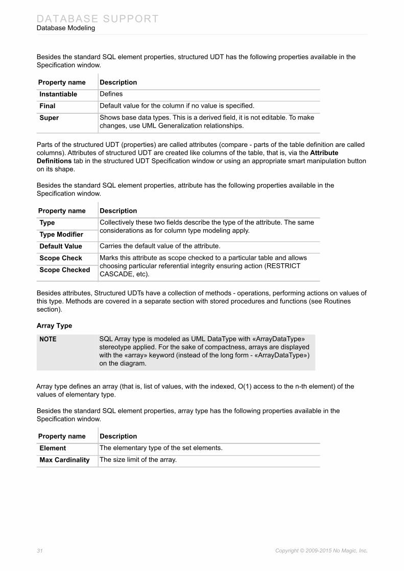
Besides the standard SQL element properties, structured UDT has the following properties available in the Specification window.
Parts of the structured UDT (properties) are called attributes (compare - parts of the table definition are called columns). Attributes of structured UDT are created like columns of the table, that is, via the Attribute Definitions tab in the structured UDT Specification window or using an appropriate smart manipulation button on its shape.
Besides the standard SQL element properties, attribute has the following properties available in the Specification window.
Besides attributes, Structured UDTs have a collection of methods - operations, performing actions on values of this type. Methods are covered in a separate section with stored procedures and functions (see Routines section).
Array Type
Array type defines an array (that is, list of values, with the indexed, O(1) access to the n-th element) of the values of elementary type.
Besides the standard SQL element properties, array type has the following properties available in the Specification window.
Property name DescriptionInstantiable Defines
Final Default value for the column if no value is specified.
Super Shows base data types. This is a derived field, it is not editable. To make changes, use UML Generalization relationships.
Property name DescriptionType Collectively these two fields describe the type of the attribute. The same
considerations as for column type modeling apply.Type ModifierDefault Value Carries the default value of the attribute.
Scope Check Marks this attribute as scope checked to a particular table and allows choosing particular referential integrity ensuring action (RESTRICT CASCADE, etc). Scope Checked
NOTE SQL Array type is modeled as UML DataType with «ArrayDataType» stereotype applied. For the sake of compactness, arrays are displayed with the «array» keyword (instead of the long form - «ArrayDataType») on the diagram.
Property name DescriptionElement The elementary type of the set elements.
Max Cardinality The size limit of the array.

32 Copyright © 2009-2015 No Magic, Inc..
DATABASE SUPPORTDatabase Modeling
Multiset Type
Multiset type defines a set of elements of the elementary type.
Besides the standard SQL element properties, multiset has the following properties available in the Specification window.
Reference Types
Reference type defines a pointer to the data of the referred type.
Besides the standard SQL element properties, reference type has the following properties available in the Specification window:
Row Type
Represents one row of the table. The difference from structured UDT is that row type represents a value stored in the table, while structured UDT represents “free-floating” value during computation. For example it is meaningful to take address for the row., but not of the structured UDT value.
Parts of the row data type (properties) are called fields (compare - parts of the table definition are called columns). Fields for row data type are created like columns of the table, that is, via the Fields tab in the row data type Specification window or using an appropriate smart manipulation button on its shape.
Besides the standard SQL element properties, field has the following properties available in the Specification window.
NOTE SQL Multiset type is modeled as UML DataType with «MultisetDataType» stereotype applied. For the sake of compactness, multisets are displayed with the «multiset» keyword (instead of the long form - «MultisetDataType») on the diagram.
Property name DescriptionElement The elementary type of the set elements.
NOTE SQL Reference type is modeled as UML DataType with «Reference-DataType» stereotype applied. For the sake of compactness, refer-ences are displayed with the «ref» keyword (instead of the long form - «ReferenceDataType») on the diagram.
Property name DescriptionReferenced Type The type of the data that is being referenced.
Scope Table Limit the references to the data of the particular table.
NOTE SQL Row Data Type is modeled as UML DataType with «RowDataType» stereotype applied. For the sake of compactness, row data types are displayed with the «row» keyword (instead of the long form - «RowDataType») on the diagram.
Property name DescriptionType Collectively these two fields describe the type of the field. The same
considerations as for column type modeling apply.Type Modifier

33 Copyright © 2009-2015 No Magic, Inc..
DATABASE SUPPORTDatabase Modeling
Sequences and Autoincrement Columns
SQL has facilities to generate sequences of numbers (0, 1, 2, 3, ...). These sequences are often used to fill in values for identifier columns - to uniquely number the row data in the table. There are 2 separate facilities:
• Standalone sequence object. This generator is not tied to any other object. Programer must explicitly query it to get the next value from the sequence and then use the retrieved value appropriately (usually in the INSERT statement to insert value for id column). Usually there are separate sequences for each table; sometimes the same sequence is reused for several columns.
• Autoincrement columns. Column of the table can be designated as autoincrement. When row is inserted into the table, if value of such column is not explicitly provided, one is generated automatically.
Figure 23 -- Example of sequence and autoincrement column modeling
Cameo Data Modeler has modeling support for both kinds of sequences.
To create a standalone sequence
Do one of the following:• Select the GLOBALS element shape on a diagram pane and click an appropriate smart
manipulation button.
Scope Check Marks this field as scope checked to a particular table and allows choosing particular referential integrity ensuring action (RESTRICT CASCADE, etc).Scope Checked
NOTES • SQL Sequence is modeled as UML Property with «Sequence» stereotype applied. For the sake of compactness, sequences are displayed with the «seq» keyword (instead of the long form - «Sequence») on the diagram.
• Autoincrement parameters (start value, increment, etc.) data is stored as a separate model element - UML OpaqueExpression, with «IdentitySpecifier» stereotype applied. This element is set as defaultValue of the Property - either sequence property (when standalone sequences are modeled) or column property (when autoincrement table columns are modeled).
Property name Description

34 Copyright © 2009-2015 No Magic, Inc..
DATABASE SUPPORTDatabase Modeling
• Right-click the GLOBALS element in the Containment tree and on its shortcut menu, select New Element > Sequence.
Autoincrement columns are also supported. To mark a column as autoincrement, you must switch the Default Value property value type from value expression to identity specifier.
To mark a column as autoincrement
1. Open the column Specification window.2. Select the Default Value property.3. Click the black-arrowed button next to the property value and select Value Specification >
IdentitySpecifier as shown in the following figure.
Figure 24 -- Marking column as autoincrement
NOTE Since a standalone sequence is modeled as a UML Property, it can not be placed directly into the Schema package.
35 Copyright © 2009-2015 No Magic, Inc..
DATABASE SUPPORTDatabase Modeling
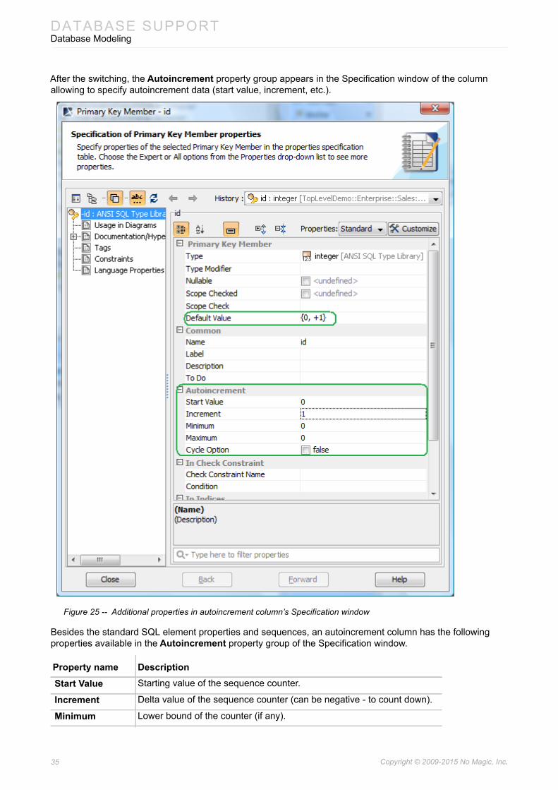
After the switching, the Autoincrement property group appears in the Specification window of the column allowing to specify autoincrement data (start value, increment, etc.).
Figure 25 -- Additional properties in autoincrement column’s Specification window
Besides the standard SQL element properties and sequences, an autoincrement column has the following properties available in the Autoincrement property group of the Specification window.
Property name DescriptionStart Value Starting value of the sequence counter.
Increment Delta value of the sequence counter (can be negative - to count down).
Minimum Lower bound of the counter (if any).

36 Copyright © 2009-2015 No Magic, Inc..
DATABASE SUPPORTDatabase Modeling
Additionally sequence has an Identity field and column has the Default Value field, where textual representation of the counter options can be entered. This feature can be used for nice displaying of the counter configuration in the diagrams (the start, inc, min, max field data is normally not visible in the diagram). Some notation convention should be adopted how to map the counter data into the text representation. For example it could be: {<start>, <inc>, <min>-<max>, <c>}. Then the counter from 0 with +1 increment, min max of 0 and 1000 and cycle option would be displayed as “{0, +1, 0-1000, C}” string. At the moment this text representation is not automatically connected to the counter field values, so synchronization has to be done by hand.
Constraints
Tables have a multitude of constraints between them. These constraints enforce the proper business semantics for the data in the database tables (relationships between data in different tables, semantical constraints of the data in the table). There are these available constraint types:
• Primary key constraints - specifying column (or a combination of columns), which uniquely identify the row in the table.
• Unique constraints. They are very similar to primary key constraints - uniquely identify the row in the table. One of the unique constraints of the table is designated as primary.
• Foreign key constraints, which establish relationships between two tables.
• Nullability constraints (NOT NULL constraint) - a simple constraint on the column, indicating that column must have value
• Check constraints establish additional checking conditions on values in the column / table.
• Assertions provide more global check than a check constraint - spanning multiple tables
• indexes are not constraints per se, but they are covered in this section because they are modeled similarly.
The primary keys, unique and check constraints, indexes can be modeled in two ways. One way is easy and simple but does not cover all the options provided by SQL. Another way is tedious, but provides full SQL coverage.
Maximum Upper bound of the counter (if any)
Cycle Option The counter can “wrap around” when it reaches the maximum (or minimum - for downwards counters)
Property name Description

37 Copyright © 2009-2015 No Magic, Inc..
DATABASE SUPPORTDatabase Modeling
Implicit Primary Key, Unique, Check Constraint, and Index Modeling
An easy way of modeling this kind of constraint is applying the «PrimaryKeyMember», «UniqueMember», «CheckMember», or «IndexMember» stereotype on the necessary column. PK, unique, and index markers can be applied on the column via its shortcut menu as shown in the following figure.
Figure 26 -- Quick application of PK, Unique, and Index markers
NOTES • SQL Primary Key (when implicitly modeled) is modeled as an additional «PrimaryKeyMember» stereotype applied on the SQL column. This variant is shown in the diagram as an additional «pk» keyword on the column in the diagram.
• SQL Unique Constraint (when implicitly modeled) is modeled as an additional «UniqueMember» stereotype applied on the SQL column. This variant is shown in the diagram as an additional «unique» keyword on the column in the diagram.
• SQL Check Constraint (when implicitly modeled) is modeled as an additional «CheckMember» stereotype applied on the SQL column. This variant is shown in the diagram as an additional «chk» keyword on the column in the diagram.
• SQL Index (when implicitly modeled) is modeled as an additional «IndexMember» stereotype applied on the SQL column. This variant is shown in the diagram as an additional «idx» keyword on the column in the diagram.

38 Copyright © 2009-2015 No Magic, Inc..
DATABASE SUPPORTDatabase Modeling
To apply a check constraint marker on a column
1. Open the Specification window of the column.2. Define the Condition property value in the In Check Constraint property group.
Thusly marked column is considered as a member of one-column constraint, specified in-line. It is by default an unnamed constraint. To specify its name, you need to define the Primary Key Name, the Unique Key Names, the Check Name, or the Index Names property value in the column Specification window.
In the SQL script (in CREATE TABLE, ADD COLUMN statements) this would correspond to the following part of the column specification:
<column name> [ <data type> ] ...[ [<constraint name>] <constraint>... ]<constraint> ::=| UNIQUE| PRIMARY KEY| CHECK '('<condition>')'
If primary key, unique constraint or index must span several columns (in this case constraint is not in-line, near the column definition, but as a separate definition at the bottom of the table definition), all the columns must be marked with the appropriate «UniqueMember» / «IndexMember» stereotype and all must have the same name. Column can participate in several unique or
Various cases of quick constraint modeling are depicted in the following figure.
Figure 27 -- Various situations, modeled with quick constraint notation
39 Copyright © 2009-2015 No Magic, Inc..
DATABASE SUPPORTDatabase Modeling
Explicit Primary Key, Unique, Check Constraint, and Index Modeling
The quick, implicit way to model constraints does not cover some cases, allowed by SQL. Constraints in SQL can be marked as DEFERABLE, INITIALY DEFERRED; constraint in the database can be in active state (enforced) or disabled. Indexes have various configuration parameters.
Modeling with the help of «XYZMember» stereotypes does not allow to specify this additional information. In this case modeling with explicit constraint model elements is necessary. This can be done from the Specification window of table. There are separate tabs for creating these constraint elements: Unique Constrains (allows creating both primary keys and unique constraints), Check Constraints, Indices. Once created, additional properties of the constraints can be specified.
Besides the standard SQL element properties, primary key and unique constraint have following properties available in the Specification window.
Check constraints have the same properties as primary key and unique constraints, and additionally have following properties available in the Specification window.
Besides the standard SQL element properties, index has the following properties available in the Specification window.
NOTES • SQL Unique Constraint (when explicitly modeled) is modeled as UML Constraint with «UniqueConstraint» stereotype applied.
• SQL Check Constraint (when explicitly modeled) is modeled as UML Constraint with «CheckConstraint» stereotype applied.
• SQL Index (when explicitly modeled) is modeled as UML Constraint with «Index» stereotype applied.
Property name DescriptionMembers Columns, constrained by this constraint (must come from the same table
where constraint is located)
Inline Whether constraint is defined near the column definition, or separately, at the bottom of the bale definition. Only one-column constraints can be inline.
Deferable Marks the constraint as deferrable.
Initially Deferred Marks the constraint as initially deferred.
Enforced Whether constraint is actively checked in the database (can be changed with the SQL statements).
Property name DescriptionCondition Condition to be checked
Property name DescriptionMembers Member columns of this index
Member Increment Type
For each member column, ASC or DESC ordering direction
Unique Index is used to enforce uniqueness
System Generated
Index is system-generated.

40 Copyright © 2009-2015 No Magic, Inc..
DATABASE SUPPORTDatabase Modeling
Foreign Keys
Figure 28 -- Foreign key example
Foreign keys describe relationships between two tables. At the detailed understanding level, foreign key is a constraint on the (group of) columns in the source / referencing table, such that for each row in the source table their value combination (tuple) is equal to the value combination (tuple) of the (group of) columns for some row in the target / referenced table.
Foreign keys also have the two ways to be modeled. The main way is described below.
The main way to model foreign keys is to draw association relationship from the referencing table to the referenced table. The relationship can be simply draw in the diagram from the smart manipulator or from the button in the diagram toolbar.
Clustered The index is clustered. Only one index per table can be clustered. Non-clustered indexes are stored separately and do not affect layout of the data in the table. Clustered index governs the table data layout (table data pages are leafs of the index tree).
Fill Factor Hash table fill factor of the index
Included Members
Additional member columns of the index. No sorting is done by these columns, however their data is included into index - this provides fast retrieval. This feature is very database-specific (AFAIK only MS SQL Server has those).
Included Member Increment Type
NOTES • SQL Foreign Key (when modeled with UML Association relationship) is modeled as UML Association with the «FK» stereotype applied.on the end of the association (UML Property), which points to the referenced table
• SQL Foreign Key (when modeled with UML Constraint) is modeled as UML Constraint with «ForeignKey» stereotype applied.
Property name Description
41 Copyright © 2009-2015 No Magic, Inc..
DATABASE SUPPORTDatabase Modeling
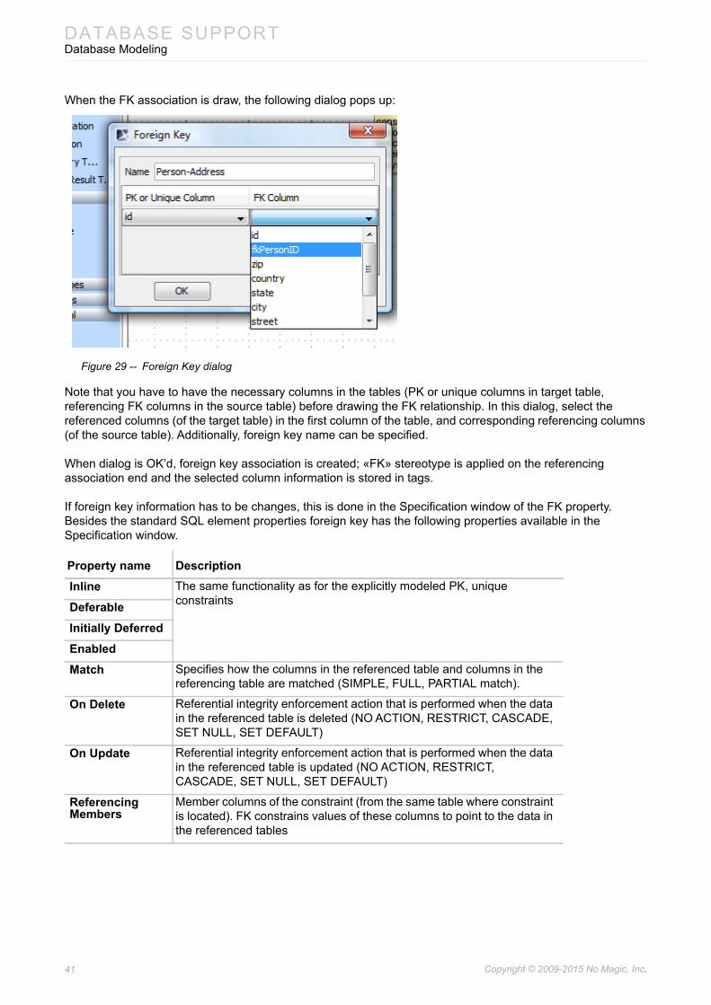
When the FK association is draw, the following dialog pops up:
Figure 29 -- Foreign Key dialog
Note that you have to have the necessary columns in the tables (PK or unique columns in target table, referencing FK columns in the source table) before drawing the FK relationship. In this dialog, select the referenced columns (of the target table) in the first column of the table, and corresponding referencing columns (of the source table). Additionally, foreign key name can be specified.
When dialog is OK’d, foreign key association is created; «FK» stereotype is applied on the referencing association end and the selected column information is stored in tags.
If foreign key information has to be changes, this is done in the Specification window of the FK property. Besides the standard SQL element properties foreign key has the following properties available in the Specification window.
Property name DescriptionInline The same functionality as for the explicitly modeled PK, unique
constraintsDeferableInitially DeferredEnabledMatch Specifies how the columns in the referenced table and columns in the
referencing table are matched (SIMPLE, FULL, PARTIAL match).
On Delete Referential integrity enforcement action that is performed when the data in the referenced table is deleted (NO ACTION, RESTRICT, CASCADE, SET NULL, SET DEFAULT)
On Update Referential integrity enforcement action that is performed when the data in the referenced table is updated (NO ACTION, RESTRICT, CASCADE, SET NULL, SET DEFAULT)
Referencing Members
Member columns of the constraint (from the same table where constraint is located). FK constrains values of these columns to point to the data in the referenced tables
42 Copyright © 2009-2015 No Magic, Inc..
DATABASE SUPPORTDatabase Modeling
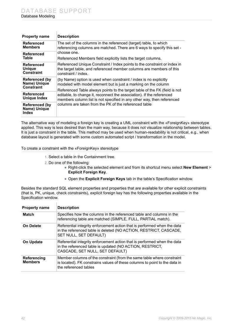
The alternative way of modeling a foreign key is creating a UML constraint with the «ForeignKey» stereotype applied. This way is less desired than the main way, because it does not visualize relationship between tables. It is just a constraint in the table. This method may be used when human-readability is not critical, e.g., when database layout is generated with some custom automated script / transformation in the model.
To create a constraint with the «ForeignKey» stereotype
1. Select a table in the Containment tree.2. Do one of the following:
• Right-click the selected element and from its shortcut menu select New Element > Explicit Foreign Key.
• Open the Explicit Foreign Keys tab in the table’s Specification window.
Besides the standard SQL element properties and properties that are available for other explicit constraints (that is, PK, unique, check constraints), explicit foreign key has the following properties available in the Specification window.
Referenced Members
The set of the columns in the referenced (target) table, to which referencing columns are matched. There are 6 ways to specify this set - choose one.Referenced Members field explicitly lists the target columns.Referenced Unique Constraint / Index points to the constraint or index in the target table, and referenced member columns are members of this constraint / index.(by Name) option is used when constraint / index is no explicitly modeled with model element but is just a marking on the columnReferenced Table always points to the target table of the FK (field is not editable, to change it, reconnect the association). If the referenced members column list is not specified in any other way, then referenced columns are taken from the PK of the referenced table
Referenced TableReferenced Unique ConstraintReferenced (by Name) Unique ConstraintReferenced Unique IndexReferenced (by Name) Unique Index
Property name DescriptionMatch Specifies how the columns in the referenced table and columns in the
referencing table are matched (SIMPLE, FULL, PARTIAL match).
On Delete Referential integrity enforcement action that is performed when the data in the referenced table is deleted (NO ACTION, RESTRICT, CASCADE, SET NULL, SET DEFAULT)
On Update Referential integrity enforcement action that is performed when the data in the referenced table is updated (NO ACTION, RESTRICT, CASCADE, SET NULL, SET DEFAULT)
Referencing Members
Member columns of the constraint (from the same table where constraint is located). FK constrains values of these columns to point to the data in the referenced tables
Property name Description

43 Copyright © 2009-2015 No Magic, Inc..
DATABASE SUPPORTDatabase Modeling
Nullability Constraint
Nullability, or NOT NULL constraint forces the condition that the column must have value. Implicit NOT NULL constraint is modeled with the nullable field of the column (set nullable=false to specify NOT NULL). This is an usual and quick way to model these constraints.
Usually there is no need to model these constraints explicitly - create a separate model element for them. But in the more complex cases these constraints can be created by hand and the «NotNullConstraint» stereotype applied on them. This allows specifying non-inline constraints, or named constraints, or deferred constraints or inactive constrains.
NOT NULL constraint does not have any additional properties in the Specification window besides the properties that all table constraints have.
Assertion
Assertion constraints are very similar to check constraints, but instead of being local to the table, they are global to the database. Assertions check some condition that must hold through several tables. Assertions are modeler as explicit constraints; there is no shorthand modeling form - assertion is always an explicit UML constraint.
To create an assertion
1. Select a schema or a database element in the Containment tree.2. Right-click the selected element and from its shortcut menu select New Element > Assertion.
Referenced Members
The set of the columns in the referenced (target) table, to which referencing columns are matched. There are 6 ways to specify this set - choose one.Referenced Members field explicitly lists the target columns.Referenced Table field just specifies the target table, referenced columns are then taken from the PK of the tableReferenced Unique Constraint / Index points to the constraint or index in the target table, and referenced member columns are members of this constraint / index.(by Name) option is used when constraint / index is no explicitly modeled with model element but is just a marking on the column
Referenced TableReferenced Unique ConstraintReferenced (by Name) Unique ConstraintReferenced Unique IndexReferenced (by Name) Unique Index
NOTE SQL NOT NULL constraint (if modeled explicitly, which is rare!) is modeled as UML Constraint with «NotNullConstraint» stereotype applied.
NOTE SQL Assertion is modeled as UML Constraint with «Assertion» stereo-type applied.
Property name Description
44 Copyright © 2009-2015 No Magic, Inc..
DATABASE SUPPORTDatabase Modeling
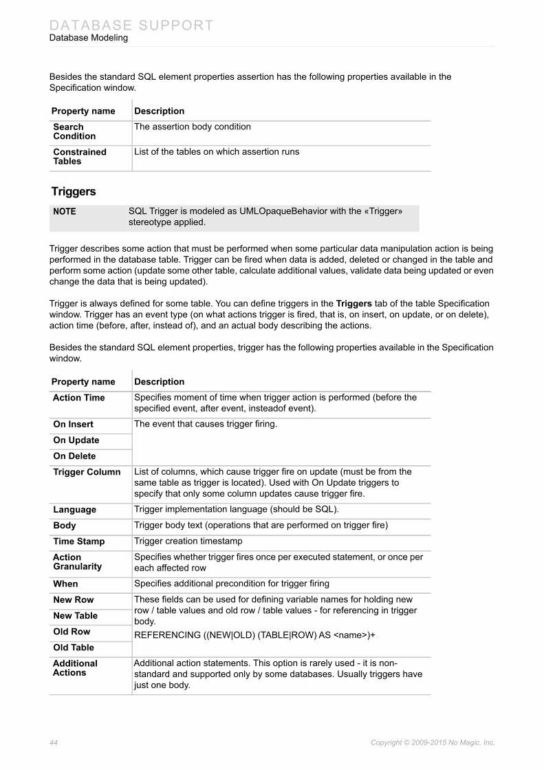
Besides the standard SQL element properties assertion has the following properties available in the Specification window.
Triggers
Trigger describes some action that must be performed when some particular data manipulation action is being performed in the database table. Trigger can be fired when data is added, deleted or changed in the table and perform some action (update some other table, calculate additional values, validate data being updated or even change the data that is being updated).
Trigger is always defined for some table. You can define triggers in the Triggers tab of the table Specification window. Trigger has an event type (on what actions trigger is fired, that is, on insert, on update, or on delete), action time (before, after, instead of), and an actual body describing the actions.
Besides the standard SQL element properties, trigger has the following properties available in the Specification window.
Property name DescriptionSearch Condition
The assertion body condition
Constrained Tables
List of the tables on which assertion runs
NOTE SQL Trigger is modeled as UMLOpaqueBehavior with the «Trigger» stereotype applied.
Property name DescriptionAction Time Specifies moment of time when trigger action is performed (before the
specified event, after event, insteadof event).
On Insert The event that causes trigger firing.
On UpdateOn DeleteTrigger Column List of columns, which cause trigger fire on update (must be from the
same table as trigger is located). Used with On Update triggers to specify that only some column updates cause trigger fire.
Language Trigger implementation language (should be SQL).
Body Trigger body text (operations that are performed on trigger fire)
Time Stamp Trigger creation timestamp
Action Granularity
Specifies whether trigger fires once per executed statement, or once per each affected row
When Specifies additional precondition for trigger firing
New Row These fields can be used for defining variable names for holding new row / table values and old row / table values - for referencing in trigger body.REFERENCING ((NEW|OLD) (TABLE|ROW) AS <name>)+
New TableOld RowOld TableAdditional Actions
Additional action statements. This option is rarely used - it is non-standard and supported only by some databases. Usually triggers have just one body.

45 Copyright © 2009-2015 No Magic, Inc..
DATABASE SUPPORTDatabase Modeling
Routines
Figure 30 -- Routines example
SQL supports several different kinds of routines. There are global routines, that are not bound to a particular type but belongs to the schema. There are two kinds of these routines - Procedures and Functions. And there are routines, that are bound to a particular structured user defined type - Methods. Each routine kind can have several parameters. Parameters have type and direction (in, out, inout). Functions and methods in SQL have return types - this is formalized in UML models by having an additional parameter with return direction kind.
There is an UML limitation, that UML does not allow to place UML operations (which are used to model SQL procedures and functions) directly in the UML packages (which are used to model SQL schemas). For this reason global routines are placed into a special container class - GLOBALS (see “GLOBALS” on page 22).
Routines can be external (written in some other languages and attached to database engine) or SQL routines. In the latter case, body of the routine can be specified in the model. Due to UML specifics, there are two ways to specify the routine body - by filling the UML method field or by filling the UML bodyCondition field of the operation. These two ways are visible in the Specification window under the field names Source (as method) and Source (as body condition). When specifying routine body, specify only one of these fields.
To use “as method” way
1. Right-click the GLOBALS element in the Containment tree and from its shortcut menu select New Element > Source. A source element (a UML OpaqueBehavior with the «Source» stereotype applied) under the GLOBALS element will be created in your schema.
2. In the Specification window of routine, edit the Source (as method) property value and in the opened dialog select the source element you’ve just created.
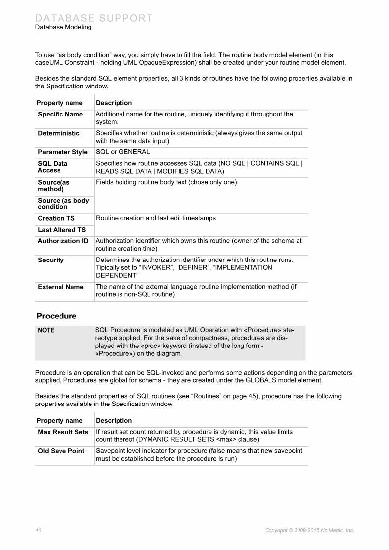
46 Copyright © 2009-2015 No Magic, Inc..
DATABASE SUPPORTDatabase Modeling
To use “as body condition” way, you simply have to fill the field. The routine body model element (in this caseUML Constraint - holding UML OpaqueExpression) shall be created under your routine model element.
Besides the standard SQL element properties, all 3 kinds of routines have the following properties available in the Specification window.
Procedure
Procedure is an operation that can be SQL-invoked and performs some actions depending on the parameters supplied. Procedures are global for schema - they are created under the GLOBALS model element.
Besides the standard properties of SQL routines (see “Routines” on page 45), procedure has the following properties available in the Specification window.
Property name DescriptionSpecific Name Additional name for the routine, uniquely identifying it throughout the
system.
Deterministic Specifies whether routine is deterministic (always gives the same output with the same data input)
Parameter Style SQL or GENERAL
SQL Data Access
Specifies how routine accesses SQL data (NO SQL | CONTAINS SQL | READS SQL DATA | MODIFIES SQL DATA)
Source(as method)
Fields holding routine body text (chose only one).
Source (as body conditionCreation TS Routine creation and last edit timestamps
Last Altered TSAuthorization ID Authorization identifier which owns this routine (owner of the schema at
routine creation time)
Security Determines the authorization identifier under which this routine runs. Tipically set to “INVOKER”, “DEFINER”, “IMPLEMENTATION DEPENDENT”
External Name The name of the external language routine implementation method (if routine is non-SQL routine)
NOTE SQL Procedure is modeled as UML Operation with «Procedure» ste-reotype applied. For the sake of compactness, procedures are dis-played with the «proc» keyword (instead of the long form - «Procedure») on the diagram.
Property name DescriptionMax Result Sets If result set count returned by procedure is dynamic, this value limits
count thereof (DYMANIC RESULT SETS <max> clause)
Old Save Point Savepoint level indicator for procedure (false means that new savepoint must be established before the procedure is run)
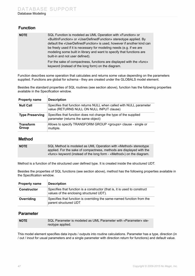
47 Copyright © 2009-2015 No Magic, Inc..
DATABASE SUPPORTDatabase Modeling
Function
Function describes some operation that calculates and returns some value depending on the parameters supplied. Functions are global for schema - they are created under the GLOBALS model element.
Besides the standard properties of SQL routines (see section above), function has the following properties available in the Specification window.
Method
Method is a function of the structured user defined type. It is created inside the structured UDT.
Besides the properties of SQL functions (see section above), method has the following properties available in the Specification window.
Parameter
This model element specifies data inputs / outputs into routine calculations. Parameter has a type, direction (in / out / inout for usual parameters and a single parameter with direction return for functions) and default value.
NOTE SQL Function is modeled as UML Operation with «Function» or «BuiltInFunction» or «UserDefinedFunction» stereotype applied. By default the «UserDefinedFunction» is used, however if another kind can be freely used if it is necessary for modeling needs (e.g. if we are modeling some built in library and want to specify that functions are built-in and not user defined).
For the sake of compactness, functions are displayed with the «func» keyword (instead of the long form) on the diagram.
Property name DescriptionNull Call Specifies that function returns NULL when called with NULL parameter
value (RETURNS NULL ON NULL INPUT clause)
Type Preserving Specifies that function does not change the type of the supplied parameter (returns the same object)
Transform Group
Allows to specify TRANSFORM GROUP <groups> clause - single or multiple.
NOTE SQL Method is modeled as UML Operation with «Method» stereotype applied. For the sake of compactness, methods are displayed with the «func» keyword (instead of the long form - «Method») on the diagram.
Property name DescriptionConstructor Specifies that function is a constructor (that is, it is used to construct
values of the enclosing structured UDT).
Overriding Specifies that function is overriding the same-named function from the parent structured UDT
NOTE SQL Parameter is modeled as UML Parameter with «Parameter» ste-reotype applied.

48 Copyright © 2009-2015 No Magic, Inc..
DATABASE SUPPORTDatabase Modeling
Besides the standard SQL element properties, parameter has the following properties available in the Specification window.
Cursor and Routine Result Table
When routine does not return a scalar value but a collection of the table values, cursor is used, instead of the parameter. Cursor has a type. This type must be some table type instead of the scalar types used for parameters. It can be an actual table / view from the model, if cursor returns values from that table, or (if cursor returns data from some SELECT statement) can be a synthetic table. A Routine Result Table model element is used for this purpose (UML Class with «RoutineResultTable» stereotype applied). It’s modeling is exactly the same as the normal tables - this is just an ephemeral table.
Besides the standard SQL element properties, cursor has the following properties available in the Specification window:
Property name DescriptionType Type of the parameter
Type ModifierDefault Value Default value (used when value is not supplied during routine
invocation).
Direction Direction of data flow through the parameter (into the routine, out of the routine or both)
Locator AS LOCATOR modifier of the type. Specifies that instead of value, means to locate value are transferred
String Type Option
Only valid when parameter type is XML type. Specifies underlying string datatype.
Cast Type Additional options, specifying that return parameter is cast from another type (possibly with locator indication).Cast Locator
NOTE SQL Cursor is modeled as UML Parameter with the «Cursor» stereo-type applied.
Property name DescriptionType Type of the cursor. Should point to the routine result table.
Type ModifierDirection Direction of data flow through the parameter (into the routine, out of the
routine, routine result)

49 Copyright © 2009-2015 No Magic, Inc..
DATABASE SUPPORTDatabase Modeling
Access Control
Figure 31 -- Access control example
SQL has means to specify and control the rules of access to various data objects. This subset of SQL language is sometimes called Data Control Language. The relevant concepts are: User, Group, Role (3 different kinds of authorization subjects), Permission and Role Authorization (2 kinds of access control rules). Possible object types for access control varies depending on database flavor, but usually Tables, User-defined Types, Domains, Routines, Sequences can be specified as the target objects of access control.
User
User object represents the single user person in the system, User is subject to access control rules.
Besides the standard SQL element properties, user has the following properties available in the Specification window.
Group
Group object represents a collection of Users. Group is subject to access control rules, and allows specifying access control rules on several users simultaneously.
Besides the standard SQL element properties, group has the following properties available in the Specification window.
NOTE SQL User is modeled as UML Actor with the «User» stereotype applied.
Property name DescriptionOwned Schema Schemas that are owned by this user,
NOTE SQL Group is modeled as UML Actor with the «Group» stereotype applied.
Property name DescriptionUser Collection of users the group is made of.
Owned Schema Schemas that are owned by this group,

50 Copyright © 2009-2015 No Magic, Inc..
DATABASE SUPPORTDatabase Modeling
Role
Role object represents a specific role (typical activities) that can be played by users. Role is subject to access control rules, and allows specifying access control rules for all subjects, playing this role.
Besides the standard SQL element properties, role has the following properties available in the Specification window.
Privilege
Privilege relationship expresses the fact that the permission to perform specified action on specified object (relationship target) is granted to specified grantee (relationship source). Grantee can be any authorization subject - Use, Group or another Role. Object can by another SQL object (the precise list of object types, that can be targeted by privileges, varies by database type).
Privilege corresponds to SQL grant privilege statement:
GRANT <action>[(<column list>)] ON <object> TO <grantee> [WITH HIERARCHY OPTION][WITH GRANT OPTION]
Besides the standard SQL element properties, privilege has the following properties available in the Specification window.
Role Authorization
Role authorization relationship expresses the fact that the specified role (relationship target) is granted to specified grantee (relationship source). Grantee can be any authorization subject - Use, Group or another Role.
Role authorization corresponds to SQL grant role statement:
GRANT <role> TO <grantee> [WITH ADMIN OPTION]
NOTE SQL Role is modeled as UML Actor with the «Role» stereotype applied.
Property name DescriptionOwned Schema Schemas that are owned by this role,
NOTE SQL Privilege is modeled as UML Dependency with the «Privilege» ste-reotype applied.
Property name DescriptionAction Specifies action that is being granted (such as SELECT or UPDATE).
Action Objects Specifies additional more narrow subobject list, on which the specified action is permitted (usually column list for SELECT or UPDATE).
Grantable Specifies that this privilege can be further re-granted to other subjects by the recipients. Corresponds to WITH GRANT OPTION part of GRANT statement.
With Hierarchy Specifies that this privilege applies to subobjects (subtables). Corresponds to WITH HIERARCHY OPTION part of the GRANT statement.
Grantor Subject, who grants this privilege to the grantees.
NOTE SQL Role Authorization is modeled as UML Dependency with «RoleAu-thorization» stereotype applied.
51 Copyright © 2009-2015 No Magic, Inc..
DATABASE SUPPORTDatabase Code Engineering
Besides the standard SQL element properties, role authorization has the following properties available in the Specification window.
Oracle Database Modeling Extensions
When the Oracle flavor is chosen for database top level element (schema or database), additional Oracle extensions are brought in. Elements that are in the scope of this schema or database element obtain additional Oracle-specific properties in the Specification windows (under the separate Oracle property group). These properties carry an additional information, that is then used when generating DDL scripts for Oracle.
Most often there is just one Additional Properties property - allowing entering free-form text that is then used when generating (this can be used to specify any extension texts - such as tablespace options for tables).
Oracle extensions provide means to model synonyms. Synonym is mapped as follows:
• Element of the same type (that is, table, materialized view, stored procedure, sequence) as the one being aliased is created. It is stereotyped as appropriate, but have no other data - just it's name is important.
• Additionally, stereotype «OraSynonym» will be applied on the element. It has ref:Element[1] tag for pointing to the element being aliased. Synonyms of synonyms are handled in the same way.
Oracle extensions provide means to model materialized views. Materialized view can be created from Oracle SQL diagram. It is an ordinary SQL view, but with the additional «OraMaterializedView» stereotype applied (in diagrams, a shortened keyword «materialized» is used for the sake of compactness).
Database Code EngineeringCameo Data Modeler provides code engineering capabilities database script generation and reverse engineering. Database model can be generated in to the DDL script, which can then be run on the database engine to create database structures. And conversely database engine can export database structures into the DDL script, which can then be reverse-engineered into the database model. In addition to that Cameo Data Modeler provides reverse engineering directly from live database through JDBC connection.
Cameo Data Modeler code engineering supports the following database dialects for script generation and reversing:
• Standard SQL
• Oracle
• MS SQL Server
• DB2
• MySQL
• PostgreSQL
• Sybase
Property name DescriptionGrantable Specifies that this role can be further re-granted to other subjects by the
recipients. Corresponds to WITH ADMIN OPTION part of GRANT statement.
Grantor Subject, who grants this role to the grantees.
52 Copyright © 2009-2015 No Magic, Inc..
DATABASE SUPPORTDatabase Code Engineering
• Pervasive
• Cloudscape / Derby
• MS Access
• Pointbase
As was mentioned earlier, database modeling was significantly extended in the version v17.0.1. But database code engineering has remained at the same level as before. Hence currently not all database concepts, that can be modeled, can be subsequently generated or reverse engineered. This situation will be amended in the future.
Code Engineering Set
Code engineering set for database scripts can be created in the same manner as CE sets for other code types (see “Code Engineering Sets” in MagicDraw CodeEngineering UserGuide.pdf). Right-click the Code engineering Sets, New, DDL, and then the appropriate database flavor. When the CE set is created, database model elements can be added to it and then DDL script file(s) can be generated OR the script files can be added to the CE set and then reverse-engineered into the database models. In addition to reversing from files, there is Reverse from DB radio button. Once it is switched, the options for JDBC connection configuring appear, allowing to set up connection to the live database.
Box name DescriptionRecently Used
Contains the list of the recently used reverse templates. Choose the one you need and click Apply.
DB Connection URL
The connection URL for the selected profile.
Driver Files Contains .jar and .zip files or directories with JDBC driver’s classes.To choose the files or directories you want to add or remove, click the ... button. The Select Files and/or Directories dialog appears.NOTE If the driver file is empty, Driver Class is searched from
the classpath.
Driver Class Contains the connection driver class. Click the ... button and the list of available driver classes that are available in the selected driver files is displayed.NOTE Only in the files that are selected in the Driver Files list,
the system searches for driver classes.
Username Type the username to connect to the database.
Password Type the password to connect to the database.
Catalog Contains a name of the selected Catalog. To retrieve the list of available Catalogs from the database, click the ... button and select the catalog. The catalog name appears in the Catalog text box.NOTE Only when all other properties in this dialog box are
correctly defined, the list of catalogs can be retrieved.
Schema Contains a name of the selected Schema. To retrieve the list of available Schemas from the database, click the ... button and select the schema. The schema name appears in the Schema text box.NOTE Only when all other properties in this dialog box are
correctly defined, the list of schemas can be retrieved.
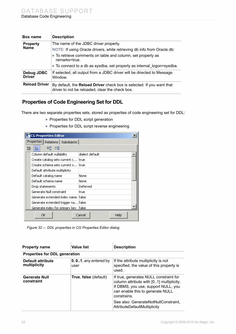
53 Copyright © 2009-2015 No Magic, Inc..
DATABASE SUPPORTDatabase Code Engineering
Properties of Code Engineering Set for DDL
There are two separate properties sets, stored as properties of code engineering set for DDL:
• Properties for DDL script generation
• Properties for DDL script reverse engineering
Figure 32 -- DDL properties in CG Properties Editor dialog
Property Name
The name of the JDBC driver property.NOTE: If using Oracle drivers, while retrieving db info from Oracle db:• To retrieve comments on table and column, set property as
remarks=true.• To connect to a db as sysdba, set property as internal_logon=sysdba.
Debug JDBC Driver
If selected, all output from a JDBC driver will be directed to Message Window.
Reload Driver By default, the Reload Driver check box is selected. If you want that driver to not be reloaded, clear the check box.
Property name Value list DescriptionProperties for DDL generationDefault attribute multiplicity
0, 0..1, any entered by user
If the attribute multiplicity is not specified, the value of this property is used.
Generate Null constraint
True, false (default) If true, generates NULL constraint for column attribute with [0..1] multiplicity. If DBMS, you use, support NULL, you can enable this to generate NULL constrains.See also: GenerateNotNullConstraint, AttributeDefaultMultiplicity
Box name Description

54 Copyright © 2009-2015 No Magic, Inc..
DATABASE SUPPORTDatabase Code Engineering
Generate extended index name
True, false (default) If true, generates index name of the form: TableName_IndexName.
Generate extended trigger name
True, false (default) If true, generates trigger name of the form: TableName_TriggerName.
Generate index for primary key
True (default), false If the DBMS, you use, requires explicit indexes for primary key, you may enable explicit index creation using this flag.See also: GenerateIndexForUnique
Generate index for unique
True (default), false If the DBMS, you use, requires explicit indexes for primary key or unique columns, may enable explicit index creation using this flag. See also: GenerateIndexForPK
Generate not Null constraint
True (default), false If true, generates NOT NULL constraint for column attribute with [1] multiplicity. If you set GenerateNullConstraint, you may wish to do not generate NOT NULL constrain. See also: GenerateNullConstraint, AttributeDefaultMultiplicity
Generate qualified names
True (default), false If value of Generate Qualified Names check box is true, package name is generated before the table or view name.For example: «Database» package “MQOnline” includes «Table» class “libraries”. Then check box Generate Qualified Names is selected as true in generated source would be written:CREATE TABLE MQOnline.libraries;Then check box Generate Qualified Names is selected as false, in generated source would be written:CREATE TABLE libraries;
Generate quoted identifiers
True, false (default) Specifies whether DDL code generator should generate quoted names of identifiers.
Object creation mode The Object Creation Mode combo box has the following options:only CREATE statementsDROP & CREATE statementsCREATE OR REPLACE statements (only for Oracle dialect; default for this dialect)DROP IF EXISTS & CREATE statements (only for MySQL dialect; default for this dialect).
Properties for DDL script reverse engineering
Property name Value list Description

55 Copyright © 2009-2015 No Magic, Inc..
DATABASE SUPPORTDatabase Code Engineering
Supported SQL Statements
This section lists SQL statements that are supported in the Cameo Data Modeler plugin. They are parsed and mapped into model constructs.
Column default nullability
Dialect default (default), not specified, NULL, NOT NULL
If column has no NULL or NOT NULL constraint specified, the value of this property is used.
Create catalog sets current catalog
True (default), false Specifies whether create catalog statement changes current catalog name.
Create schema sets current schema
True (default), false Specifies whether create schema statement changes current schema name.
Default catalog name DefaultCatalogNone (default), DefaultCatalogPackage, any entered by the user
Specifies current database name. Used when DDL script does not specify database name explicitly.
Default schema name DefaultSchemaNone(default), DefaultSchemaPackage, any entered by the user
Specifies current schema name. Used when DDL script does not specify schema name explicitly.
Drop statements Deferred (default), Immediate, Ignored
Specifies whether execution of drop statements may be deferred, or must be executed, or must be ignored. Deferred drop may be enabled if elements are recreated later. This will save existing views. Attribute stereotypes, multiplicity and default value always are not dropped immediately.
Map Null / not Null constraints to
Stereotypes (default), Multiplicity
When parsing DDLs, the null / not null constraints are modeled as either stereotype tag values or multiplicity.
Map foreign keys True (default), false An association with «FK» stereotype on the association end is created, to represent Foreign Key.
Map indexes True (default), false A constraint with «Index» stereotype is added into table, to represent index.
Map triggers True (default), false An opaque behavior with «Trigger» stereotype is added into table to represent trigger.
Map views True (default), false A class with «ViewTable» stereotype is created to represent view.
Property name Value list Description

56 Copyright © 2009-2015 No Magic, Inc..
DATABASE SUPPORTDatabase Code Engineering
The following table provides SQL2 SQL schema statements and their support status in the Cameo Data Modeler plugin (Yes means that a statement can be generated into DLL script from model constructs and reverse engineered from script into model constructs).
Some SQL schema statements (e.g. schema definition, table definition) allow implicit catalog name and unqualified schema name. In addition to SQL schema statements, the following SQL session statements must be supported:
• Set catalog statement - sets the current default catalog name.
• Set schema statement - sets the current default unqualified schema name.
Cameo Data Modeler supports the following widely used by dialects statements that are not the part of SQL2:
• Database definition statement (CREATE DATABASE) that creates database
• Index statements (CREATE INDEX, DROP INDEX) that create an index on table and remove it
• Trigger statements (CREATE TRIGGER, DROP TRIGGER) that create a trigger on table and remove it.
The following table provides details on mapping on the supported SQL schema manipulation statements into SQL constructs.
SQL schema statement Supported (Yes / No)SQL schema definition statement
Schema definition Yes
Table definition Yes
View definition Yes
Alter table statement Yes
Grant statement No
Domain definition No
Assertion definition No
Character set definition No
Collation definition No
Translation definition No
SQL schema manipulation statement
Drop table statement Yes
Drop view statement Yes
Revoke statement No
Alter domain statement No
Drop assertion statement No
Drop domain statement No
Drop character set statement No
Drop collation statement No
Drop translation statement No
DDL Statement or Concept Action, model Item
Description Visible
Alter table statement Modify class Elements: table name and alter table action. Alter table action – one of: add column, add table constraint, alter column, drop table constraint, drop column.
Yes

57 Copyright © 2009-2015 No Magic, Inc..
DATABASE SUPPORTDatabase Code Engineering
DDL Dialects
This section reviews Cameo Data Modeler support for DDL script flavors from different vendors.
Standard SQL2
For SQL2 statements supported by Cameo Data Modeler see Section Supported SQL Statements, “Supported SQL Statements”, on page 55.
MagicDraw UML schema package is located within a database package. Database definition statement is not the part of the SQL2 standard - it is an analogue of a Database (a Catalog).
Oracle
Cameo Data Modeler Oracle DDL script generation is based on the Velocity engine. This provides ability to change generated DDL script by changing velocity template. In this chapter we will introduce how Oracle DDL generation works in MagicDraw, how to change template for some specific things.
Knowledge of the Velocity Template Language is necessary for understanding, editing, or creating templates. Velocity documentation can be downloaded from: http://click.sourceforge.net/docs/velocity/Velocity-UsersGuide.pdf.
For more information about Oracle DDL generation and customization, see MagicDraw OpenAPI UserGuide.pdf.
Oracle dialect
For more information about Oracle DDL 11g, see http://download.oracle.com/docs/cd/B28359_01/ server.111/b28286/toc.htm
Add column definition Define attribute Elements: column definition. Yes
Add table constraint definition
Define method Elements: table constraint definition. Yes
Alter column definition Modify attribute Elements: mandatory column name, default clause (for add default statement only).
Yes
Drop table constraint definition
Delete method Elements: constraint name, drop behavior
Yes
Drop column definition Delete attribute Elements: column name, drop behavior Yes
Drop schema statement Delete package Elements: schema name, drop behavior Yes
Drop table statement Delete class Elements: table name, drop behavior Yes
Drop view statement Delete class Elements: table name, drop behavior Yes
Drop behavior Action property Modifiers: CASCADE, RESTRICT No
NOTE A Catalog has no explicit definition statement. If a database package for a Catalog does not exist, it should be created (when it is referred for the first time).
DDL Statement or Concept Action, model Item
Description Visible

58 Copyright © 2009-2015 No Magic, Inc..
DATABASE SUPPORTDatabase Code Engineering
Oracle dialect has CREATE DATABASE, CREATE INDEX, and CREATE TRIGGER statements that are not the part of SQL2 standard but that are taken into account while reversing DDL script of this dialect.
This dialect has some syntax differences from SQL2 standard because of extensions (e.g. some schema definition statements can have STORAGE clause). These extensions are ignored while reversing.
Code engineering features for Oracle dialect are more extensive that code engineering for other dialects. In addition to the concepts, supported by Standard SQL generation, Oracle generation supports generation and reverse of:
• Sequences
• Synonym
• Structured user-defined types (with methods, map & order functions)
• Function and Procedure
• Users, Roles Grants
• Materialized Views
Cloudscape
Informix Cloudscape v3.5 dialect has no database definitions statement. A database package with the name specified by CurrentDatabaseName property is used.
This dialect has CREATE INDEX and CREATE TRIGGER statements that are not the part of a SQL2 standard but that should be taken into account while reversing DDL script of this dialect.
This dialect has some syntax differences from SQL2 standard because of extensions (e.g. some schema definition statements can have PROPERTIES clause). These extensions are ignored while reversing.

Copyright © 2009-2015 No Magic, Inc.59
TRANSFORMATIONS
Introduction
The Cameo Data Modeler plugin for MagicDraw provides a set of transformation for transforming between various kinds of data models. There are transformations for transforming:
• UML models to SQL models (2 flavors - generic and Oracle)
• ER models to SQL models (2 flavors - generic and Oracle)
• SQL models to UML models (suitable for all flavors of databases)
• UML models to XML schema models
• XML schema models to UML models
After the transformation, user can further refine the resulting model as necessary, and generate the artifact files from those models. Actual DDL scripts, XML schema files can be generated using the code engineering facilities.
Since the Cameo Data Modeler plugin provides more powerful modeling and generation features for Oracle database flavor (there are Oracle-specific modeling extensions, and code engineering features for Oracle database scripts cover more features), there are two separate transformation flavors as well - “ER to SQL (Generic)” and “ER to SQL (Oracle)”.
Functionality of performing model transformations in MagicDraw is accessible by the Model Transformations Wizard. The wizard is used for creating new transformations.
To open the Model Transformations Wizard
Do one of the following:• From the Tools menu, choose Model Transformations.
• Select one or more packages. From the shortcut menu, choose Tools > Transform.
NOTE Transformation engine implementation code is available from the MagicDraw Standard Edition upwards. However, there are just a couple of transformations in the MagicDraw (Any-to-Any and Profile Migration transformations). The Cameo Data Modeler plugin brings in a set of transformations between various kinds of data models.
NOTE As of version 17.0.1 the Generic-Oracle DDL(SQL) transformation is no longer available in MagicDraw. The transformation is no longer needed, because of unification of previously separate profiles for generic SQL and Oracle SQL modeling.
NOTE For more information about this wizard, see “Model Transformation Wizard” in MagicDraw UserManual.pdf.

60 Copyright © 2009-2015 No Magic, Inc..
TRANSFORMATIONSUML to SQL Transformation
Each transformation has its own default type map for replacing data types from the source domain into the appropriate data types of the result domain. If this type map is not suitable, the default type map can be modified or an entirely different type map can be provided if necessary.
UML to SQL TransformationThere are two very similar UML to DDL transformations:
1. UML to SQL (Generic)2. UML to SQL (Oracle)
These transformations convert the selected part of a UML model with class diagrams into Generic or Oracle SQL models with Oracle SQL diagrams respectively.
Transformation Procedure
UML to SQL (Generic / Oracle) transformation is based on the same copy mechanism as the other transformations are. It copies the source model part to the destination (unless the in-place transformation is performed), remaps types, and then performs model reorganization to turn the model into an SQL model.
To transform a UML model to SQL
1. Open the UML model you want to transform or create a new one.2. Open the Model Transformation Wizard. Do one of the following:
• On the main menu, click Tools > Model Transformations.
• Select the package in the Model Browser and click Tools > Transform on it’s shortcut menu.
3. Perform the steps of the wizard:
3.1 Select the transformation type.3.2 Select the transformation source and specify the location wherein the output
should be placed. If you open the wizard from the shortcut menu of a package, this package and all it’s content will be automatically selected as the source.
3.3 Check type mappings. You can select the transformation type map profile in this step.
3.4 Specify transformation details.
4. Click Finish when you are done.
Conversion of Classes
UML classes from the source model are converted into tables.
NOTE • For more information on how to create your own transformation rules or change mapping behavior, see “Transformation Type Mapping” in the MagicDraw UserManual.pdf.
• For more information on how to set up the mapping, watch the “Transformations” online demo at http://www.nomagic.com/support/demos.html.
61 Copyright © 2009-2015 No Magic, Inc..
TRANSFORMATIONSUML to SQL Transformation
Each property of the source class becomes a column in the result table. If a property in the UML model had the explicit multiplicity specified, nullable=true (for [0..1] multiplicity in source property) and nullable=false (for [1] multiplicity in source property) marking is applied on result columns.
Operations contained in the source class are not copied into the result table.
Primary Keys Autogeneration
If a UML class in the source model had no primary key (it is declared by applying an appropriate stereotype), an ID column is generated and marked as the primary key (PK).
The Autogenerated PK name template transformation property governs the name of the generated ID column. The %t pattern in the name template is expanded to the current table name.
The Autogenerated PK type transformation property determines the type of the ID column. The default type is integer.
Sequence Autogeneration
For each single-column PK in the destination a sequence object can be generated.
The Autogenerate Sequences transformation property governs the sequence autogeneration. Possible choices for setting the property value are as follows:
1. Do not generate sequences choice switches sequence generation off. 2. Generate sequences for all single-column PKs choice switches sequence generation on.3. Generate sequences for all autogenerated PKs choice switches sequence generation on but
only for those PKs that there automatically generated by the tool (but not for PKs which were declared by the user).
Conversion of Associations
One-to-one and one-to-many associations between classes in the source UML model are converted to foreign key relationships and to foreign key columns in the table, which is at the multiple end.
The Autogenerated FK column name template transformation property governs the name of the generated FK column. A name template can use the following patterns:
• %t is replaced by the name of the table, the foreign key is pointing to.
• %k is replaced by the key name, this foreign key is pointing to.
• %r is replaced by the name of the relationship role, which is realized by this foreign key.
Note that the type of the FK column matches the type of the PK column, to which this key is pointing.
TIP! You can turn off the automatic generation of PKs during the model trans-formation. For this, click to clear the Autogenerate PK check box in the Transformation Details pane (the 4th step of the Model Transforma-tion Wizard)
In this case you must specify PKs and FKs manually after the model transformation!
NOTE This feature is only available in UML to SQL (Oracle) transformations. Generic SQL models do not have sequence support yet.

62 Copyright © 2009-2015 No Magic, Inc..
TRANSFORMATIONSUML to SQL Transformation
Many-to-Many associations are transformed into the intermediate table. An intermediate table is generated for an association and has two FK relationships pointing to the tables at association ends. FK are generated in the same way as for one-to-many associations.
The Autogenerated table name template transformation property governs the name of the generated intermediate table (%t1 and %t2 are replaced by the names of the tables at relationship ends).
You can create your own Autogenerated FK constraint name template. It makes easier to find FKs in the generated code. Also it is helpful if you have some naming convention at your company.
You can use the same described patterns to specify the FK name template. For example, if you define the FK constraint name template as “fk_%r”, appropriate relations in the model will look like it is depicted in the following figure.
Figure 33 -- Example of transformation when FK name template is used
The same sample in the, for example, SQL code will look as follows:
CREATE SEQUENCE pets.Dog_SEQ;
CREATE SEQUENCE pets.Human_SEQ; CREATE TABLE pets.Human(
Name varchar (255),id integer,PRIMARY KEY(id)
); CREATE TABLE pets.Dog(
Name varchar (255),id integer,fk_Humanid integer NOT NULL,PRIMARY KEY(id),CONSTRAINT fk_Master FOREIGN KEY(fk_Humanid) REFERENCES pets.Human (id)
);
To create the FK constraint name template
1. In the Transformation Details (the 4th step of the Model Transformation Wizard), click the Autogenerated FK constraint name template specification cell. The Edit button appears.
2. Click the Edit button and, in the opened Autogenerated FK constraint name template dialog, define the FK name template. You can use specific names and patterns, such as %t (a table name) or %r (a relationship role) in the name template definition.
3. Click OK when you are done and continue the transformation setup process.
Conversion of Identifying Associations
Some relationships in the source model are treated as identifying relationships. In case of identifying a relationship, the objects of the class, which is at the multiple end of the association, are not independent, that is, they can exist only in association with the objects at the singular end of the association. In the resulting SQL model, the FK of these relationships is included into the PK of the table.
The PK of the dependent table is composite and contains two columns as a result:

63 Copyright © 2009-2015 No Magic, Inc..
TRANSFORMATIONSUML to SQL Transformation
1. ID column of the table2. FK to the independent table
Unfortunately UML models lack model data and notation to specify, which associations are identified. Hence transformation has to guess this. It uses the following heuristics - the composite associations are treated as identifying, while the other associations are not.
The Treat composition relationships as identifying transformation property governs these heuristics. If this property set to false, all associations are treated as not identifying.
Conversion of Multivalued Properties
In UML models, properties can be multi-valued (e.g. [0..7], [2..*]). However in databases columns they can be only single-valued. Transformation uses two strategies to handle multi-valued properties in the source model.
If the upper multiplicity limit is small and fixed, e.g., [0..3], then columns are simply multiplied the necessary number of times. The result table will have multiple columns with sequence numbers appended to their names (like “phone1”, “phone2”, and “phone3” columns in the result for a single phone[0..3] property in the source).
The Max Duplicated Columns transformation property governs the maximum number of columns, that are generated using this strategy.
If the upper multiplicity upper bound is larger than this limit or unlimited, then an auxiliary value table is generated for such multi-valued properties. This table is FK-related to the main table of the class, and holds a “value” column for storing property values.
The Value table name transformation property governs the name of the generated table (%t in this property is replaced by the name of the table and %r - by the property name). So, the table name template “%t_%r_VALUES” gives a “Person_Phone_VALUES” table name for the Person::phone property).
Conversion of Generalizations
In UML, generalizations are used extensively, while SQL domain lacks the concept of generalizations. Hence during the transformation, generalization trees are transformed into different concepts to simulate the generalization approximately.
There are three different strategies for simulating generalizations in the result domain:
1. Multiple Tables, Decomposed Object strategy.2. Multiple Tables, Copy Down strategy.3. One Table, Merged strategy.
Specify the strategy for converting generalization trees in the Generalization Tree transformation strategy transformation property.
Multiple Tables, Decomposed Object strategy
This strategy consists of the following actions:
1. Each class is converted to a separate table.2. Direct (not inherited) properties of the class are converted to the columns of the table.3. A foreign key to the table of the base class is created. The table of the base class carries the
inherited columns.4. Primary keys of all the classes participating in a hierarchy tree are the same (there can be
several hierarchy trees in the same transformation source, and each one is handled separately). PK of the specific tables is also a FK to the parent table.

64 Copyright © 2009-2015 No Magic, Inc..
TRANSFORMATIONSUML to SQL Transformation
This strategy is the closest one to UML and fits nicely from theoretical standpoint since there is no data duplication. The only problem of this approach is the performance of data retrieval and storage. During the storing operation, objects are decomposed into several parts, each stored in a different table (that is why the strategy is called Decomposed Object strategy), and for retrieving the object you have to query several tables (with resulting multi-level joins).
Multiple Tables, Copy Down strategy
This strategy consists of the following actions:
1. Each class is converted to a separate table.2. The table of each class holds columns for properties of that class AND all the columns, copied
from the base class (that is why this strategy is called Copy Down strategy).
As a result each table possesses the complete column set to carry data about an object of particular type. All the data of the object is stored in one table.
The weak point of this strategy is that the association relationships between tables are copied down also. Hence each association in the source can produce many foreign keys in the target. Writing SQL queries against this database layout is not very convenient. Also, if you want to retrieve all the objects of the particular class, you have to query several tables and union the results.
One Table, Merged strategy
This strategy consists of the following actions:
1. All the classes in the generalization hierarchy are folded into one large table.2. All the properties of all the classes become table columns (note that columns that were
mandatory in the specific classes become optional in the merged table).3. A separate selector column is generated, which indicates the type of the object carried by the
particular line.
The Selector Column Name, Selector Column Type and Selector Column Type Modifier transformation properties determine the selector column format.
This strategy is suitable for very small hierarchies usually of just one hierarchy level with a couple of specialization classes, each adding a small number of properties to the base class. E.g., general class “VehicleRegistration” and a couple of subclasses: “CarRegistration” and “TruckRegistration”.
This strategy suites simple cases well. It is simple and fast. However it does not scale for larger hierarchies and produces sparse tables (tables with many null values in the unused columns) in this case.
Conclusions and future improvements
Note that all hierarchies from the transformation source are converted using the same method. You cannot choose different strategies for each particular case of the generalization tree. This is considered as a future improvement for the transformations.
Conversion of DataTypes
You can choose two strategies to transform datatype of data to SQL:

65 Copyright © 2009-2015 No Magic, Inc..
TRANSFORMATIONSUML to SQL Transformation
• To transform datatypes to structured user defined types. This is a default case.
Figure 34 -- Example of datatype transformation to structured user defined types
The same sample in the, for example, Oracle SQL code will look as follows:
CREATE SEQUENCE Shapes.Shape_SEQ; CREATE OR REPLACE TYPE Shapes.integer AS OBJECT NOT FINAL INSTANTIABLE;/ CREATE OR REPLACE TYPE Shapes.Point2D AS OBJECT
(X integer,Y integer) NOT FINAL INSTANTIABLE;
/ CREATE OR REPLACE TYPE Shapes.Rectangle AS OBJECT
(upperLeft Point2D,lowerRight Point2D) NOT FINAL INSTANTIABLE;
/ CREATE TABLE Shapes.Shape(
rect Rectangle,id integer,PRIMARY KEY(id)
); • To expand datatypes into separate columns at the point of usage. Each property of a class
having a datatype as a type is expanded into a set of columns—one column per each attribute of the datatype (including inherited attributes). Column types are copied from the source datatype attribute types (modulo the transformation type mapping). If the original datatype
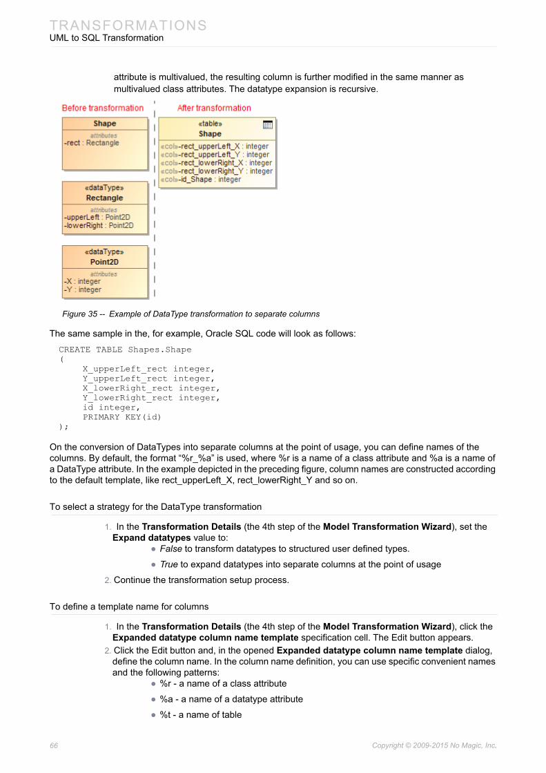
66 Copyright © 2009-2015 No Magic, Inc..
TRANSFORMATIONSUML to SQL Transformation
attribute is multivalued, the resulting column is further modified in the same manner as multivalued class attributes. The datatype expansion is recursive.
Figure 35 -- Example of DataType transformation to separate columns
The same sample in the, for example, Oracle SQL code will look as follows:
CREATE TABLE Shapes.Shape(
X_upperLeft_rect integer,Y_upperLeft_rect integer,X_lowerRight_rect integer,Y_lowerRight_rect integer,id integer,PRIMARY KEY(id)
);
On the conversion of DataTypes into separate columns at the point of usage, you can define names of the columns. By default, the format “%r_%a” is used, where %r is a name of a class attribute and %a is a name of a DataType attribute. In the example depicted in the preceding figure, column names are constructed according to the default template, like rect_upperLeft_X, rect_lowerRight_Y and so on.
To select a strategy for the DataType transformation
1. In the Transformation Details (the 4th step of the Model Transformation Wizard), set the Expand datatypes value to:
• False to transform datatypes to structured user defined types.
• True to expand datatypes into separate columns at the point of usage
2. Continue the transformation setup process.
To define a template name for columns
1. In the Transformation Details (the 4th step of the Model Transformation Wizard), click the Expanded datatype column name template specification cell. The Edit button appears.
2. Click the Edit button and, in the opened Expanded datatype column name template dialog, define the column name. In the column name definition, you can use specific convenient names and the following patterns:
• %r - a name of a class attribute
• %a - a name of a datatype attribute
• %t - a name of table

67 Copyright © 2009-2015 No Magic, Inc..
TRANSFORMATIONSUML to SQL Transformation
3. Click OK when you are done and continue the transformation setup process.
The column name template is defined in the Expanded datatype column name template property.
Conversion of Enumerations
When transforming enumerations, you can choose two strategies:
• To transform the enumeration to check constraints at the point of usage. This is the default case. Every class attribute of the enumeration type in the transformation source is transformed to the table column of a char type.
Figure 36 -- Example of enumeration transformation to check constraints
The same sample in the, for example, SQL code will look as follows:
CREATE TABLE Enumeration_CheckConstraint.Account(
currency char (3),id_Account integer,CHECK(currency in ('EUR', 'JPY', 'LTL', 'USD')),PRIMARY KEY(id_Account)
);
• To transform enumerations to lookup tables. This strategy can handle the more complex enumerations, for example, enumerations having their own attributes. The lookup table is automatically populated with enumeration literal values, and INSERT statements are generated during the SQL code generation. For each attribute that enumeration source has (including inherited attributes) the column in the target table is created. Attributes are transformed using the normal transformation rules for class attributes (including the type mapping, data type expansion, if requested, and multivalue-attribute expansion). The name column is added to the lookup table and the primary key is automatically generated, see “Primary Keys Autogeneration” on page 61. Every class attribute of the enumeration type in the transformation

68 Copyright © 2009-2015 No Magic, Inc..
TRANSFORMATIONSUML to SQL Transformation
source is transformed to the foreign key.
Figure 37 -- Example of enumeration transformation to lookup tables
The same sample in the, for example, SQL code will look as follows:
CREATE TABLE Enumeration_LookupTables.Currency(
longDescription varchar (255),USDRate,id_Currency integer,name char (3) NOT NULL,PRIMARY KEY(id_Currency)
);INSERT INTO Enumeration_LookupTables.Currency(id_Currency, name) VALUES(0, 'EUR');INSERT INTO Enumeration_LookupTables.Currency(id_Currency, name) VALUES(1, 'JPY');INSERT INTO Enumeration_LookupTables.Currency(id_Currency, name) VALUES(2, 'LTL');INSERT INTO Enumeration_LookupTables.Currency(id_Currency, name) VALUES(3, 'USD'); CREATE SEQUENCE Enumeration_LookupTables.Currency_SEQ;
CREATE SEQUENCE Enumeration_LookupTables.Account_SEQ; CREATE TABLE Enumeration_LookupTables.Account(
currency integer,id_Account integer,PRIMARY KEY(id_Account),FOREIGN KEY(currency) REFERENCES Enumeration_LookupTables.Currency
(id_Currency));
To select a strategy for the Enumeration transformation
1. In the Transformation Details (the 4th step of the Model Transformation Wizard), click the Enumeration transformation strategy specification cell. The list of available strategies appears. Select one of the following:
• Check Constraints to transform the enumeration to check constraints at the point of usage.

69 Copyright © 2009-2015 No Magic, Inc..
TRANSFORMATIONSUML to SQL Transformation
• Lookup Table to transform enumeration to lookup tables.
2. Continue the transformation setup process.
Package Hierarchy Reorganization
UML models usually have a moderately deep package nesting organization, while SQL models can have at most one package level - the schemas. Hence during the transformation, packages should be reorganized.
The Change package hierarchy transformation property governs the package reorganization. Possible choices for setting the property value are as follows:
1. Leave intact choice switches reorganization off.2. Flatten packages choice forces flattening of the packages of the source, leaving only the top
level packages in the destination. 3. Strip packages choice removes all packages of the source.
Naming of Transformed Elements
While transforming your UML models to SQL, you can modify names of the transformed elements according to given naming rules. There are several predefined rules:
• Replace spaces or special characters in the element name with the underscore sign “_”. For example, the name in source “Customer Profile” and “Terms&Conditions” could be transformed as “Customer_Profile” and “Terms_Conditions” accordingly.
• Capitalize element names after the transformation. For example, the name in source “Customer” could be transformed as “CUSTOMER”.
• Pluralize element names after transformation. For example, the name in source “Customer” could be transformed as “Customers”.
• Detect the camel case edge in element names on transformation. For example, the name in source “CustomerProfile” could be transformed as “Customer_Profile”.
To select a naming rule
1. In the Transformation Details (this is the last step of the Model Transformation Wizard), click the Name conversion rules specification cell. The cell expands and the Edit button appears.
2. Click the Edit button. The Select Opaque Behavior «Naming Rule» dialog opens.3. In the opened dialog, select naming rules you want to use in transforming element names. You
may select more than one rule.
Naming rules are as follows:
NOTE • Be sure the search includes auxiliary resources! To turn on the appropriate search mode, click Include elements from modules into search results.
• To select several naming rules, click the Multiple Selection button.
Rule name Description ExampleCamelCaseSeparator Detects all the occurrences in the original name of the
situation where lower case letter is followed by upper case letter and insert the underscore sign '_' character between.
CustomerProfile > Customer_Profile

70 Copyright © 2009-2015 No Magic, Inc..
TRANSFORMATIONSUML to SQL Transformation
For more information about selecting elements, see “Selecting an Element” in MagicDraw UserManual.pdf.4. Click OK when you are done.
You can also create your custom naming rules using structured expressions or various scripts. The naming rule is an executable opaque behavior. For more information about executable opaque behaviors, see “Creating executable opaque behaviors” in MagicDraw UserManual.pdf. The following procedure describes one of the possible ways to create a custom naming rule.
To create a custom naming rule
1. Create a package for the naming rule data.2. In this package, create an Opaque Behavior with the following parameters exactly in the same
order as follows:
• sourceElement : Element
• targetElement : Element
• initialName : String
The return parameter is of a java.lang.Object type.
3. Use the Model Transformation Profile.mdzip module. On the main menu, click File > Use Module. The required module is located in the <install.root>\profiles\Model_Transformation_Profile.mdzip. Click Finish after you have selected the module.
4. In the Model Browser, select the Opaque Behavior you have created and apply the «NamingRule» stereotype on it. Open the opaque behavior’s shortcut menu and click Stereotype. In the opened Select Stereotype list, select the «NamingRule» stereotype and click Apply.
5. Open the opaque behavior’s Specification window and specify the Body and Language property. Actually, this is a property where you define your custom naming rule. Click property specification cell and then click the Edit button.
LowerCase All Unicode letter characters in the source name are converted to their lower case version in the result name. Other character are passed through unchanged.
CUSTOMER 1 > customer 1
Pluralization All original names that do not end with character 'S' or 's' will have the 's' character appended.
Customer > Customers
SpecialCharacterEscape All Unicode characters in the source name that are not letters and not numbers are converted to an underscore sign ‘_’ in the result name. Other character are passed through unchanged.
Terms&Conditions > Terms_Conditions
UpperCase All Unicode letter characters in the source name are converted to their upper case version in the result name. Other character are passed through unchanged.
Customer 1 > CUSTOMER 1
WhitespaceEscape All Unicode whitespace characters in the source name are converted to an underscore sign ‘_’ in the result name. Other character are passed through unchanged.
Customer 1 > Customer_1
Rule name Description Example

71 Copyright © 2009-2015 No Magic, Inc..
TRANSFORMATIONSUML to SQL Transformation
6. In the opened Body and Language dialog, select a language for defining your naming rule and create the rule’s body.
7. Click OK when you are done. The naming rule you have created appears in the Name conversion rules selection list.
Transforming documentation
Documentation can be copied either with or without HTML formatting information. If you need to retain the formatting information, click to select the Allow HTML in comments check box in the Transformation Details pane (the 4th step of the Model Transformation Wizard).
The model element documentation is turned into SQL comments during the DDL script generation.
NOTE • The SQL language is not suitable for defining naming rules.• If you choose the Structured Expression language, turn on the
Expert mode to get the all list of possible operations.
TIP! You can turn off the comment generation. For this, do the following:1. From the Options menu, select Project. The Project Options dialog opens.2. Select DDL Language Options on the left (you may need to expand the Code
Engineering node). The appropriately named pane opens on the right.3. Click to clear the Generate documentation check box.4. Click OK.

72 Copyright © 2009-2015 No Magic, Inc..
TRANSFORMATIONSUML to SQL Transformation
Figure 38 -- SQL comments with and without HTML formatting information
Excluding elements from transformation
Elements can be excluded from the transformation in one of the following ways:
• By deselecting these elements in the 2nd step of the Model Transformation Wizard.
• By specifying rules for the automatic exclusion of elements in the 4th step of the wizard. These rules must be defined as executable opaque behaviors.
To define a rule for automatic elements’ exclusion
1. Create an executable opaque behavior.
For more information, see “Creating executable opaque behaviors” in MagicDraw UserManual.pdf.
2. Create an input parameter, whose type is Element, the abstract UML metaclass, and multiplicity is [1].
3. Create a return parameter, whose type is java.lang.Object and multiplicity is [1].4. Specify the Language and Body property value for the new opaque behavior.

73 Copyright © 2009-2015 No Magic, Inc..
TRANSFORMATIONSUML to SQL Transformation
To specify the rules for the automatic elements’ exclusion from the transformation
1. In the Transformation Details pane (the 4th step of the Model Transformation Wizard), click the Elements exclusion rules specification cell. The Edit button appears.
2. Click the button and select one or more rules in the Select Opaque Behavior dialog.3. Click OK when you are done and continue the transformation setup process.
EXAMPLE Let’s say we need to exclude from the transformation all the classes with the «pendingReview» stereotype applied.
For this, we must do the following:
1. Select StructuredExpression as language of the opaque behavior body.2. Define the body by creating a TypeTest operation, which takes the
collection of elements and returns only the ones with the «pendingReview» stereotype applied (see the following figure).
For more information about the TypeTest operation, see “Calling operations from the model” in MagicDraw UserManual.pdf.

74 Copyright © 2009-2015 No Magic, Inc..
TRANSFORMATIONSUML to SQL Transformation
Figure 39 -- Example of transformation with excluded class
Type Mapping
Default type maps of the UML to SQL (Generic / Oracle) transformations remap the types that are commonly used in the UML modeling domain (such as String) into types that are suitable for SQL domain (such as varchar).
UML to SQL Type Map
The default type map for these transformations is stored in the UML to SQL Type Map profile and automatically gets attached to your project at the 3rd step (the type mapping step) of the transformation wizard. If necessary it can be changed.

75 Copyright © 2009-2015 No Magic, Inc..
TRANSFORMATIONSUML to SQL Transformation
The Default map carries the following type conversions.
If you have a situation when one type map imports another type map, you can specify another default mapping rule. Such situation appears, for example, in the Oracle type map, inheriting from the Standard type map where the Oracle mapping rule String-->varchar2 overrides the base mapping rule String-->varchar. For more information about the type mapping, see “Transformation Type Mapping” and “Controlling Type Mapping Rule Behavior” in MagicDraw UserManual.pdf.
Source Type Result TypeString varchar (default)
varchar2char varyingcharacter varyingnvarcharnvarchar2nchar varyingnational char varyingnational character varyinglongvarcharlong varcharcharcharacterncharnational charnational characterlong char
short smallint
long number(20)
Integer integer
int int
float float
double double precision
date date
char char(default)characterncharnational charnational character
byte number(3)
boolean number(1)
NOTE This feature is available with MagicDraw 18.0 SP1 or later.

76 Copyright © 2009-2015 No Magic, Inc..
TRANSFORMATIONSUML to SQL Transformation
Transformation Properties
This is the complete list of properties available in UML to SQL(Generic / Oracle) transformation in the Model Transformation Wizard (for more information about this wizard, see “Model Transformation Wizard” in MagicDraw UserManual.pdf).
Figure 40 -- Model Transformation Wizard for UML to SQL (Generic / Oracle) transformation. Specify Transformation Details wizard step
Property name DescriptionAutogenerated PK name template
If the class has no PK column in the ER model, this transformation parameter for the autogenerated column name will generate the PK. You may specify the pattern for the PK name. Default "id_%t", where %t is replaced by the name of the table.
Autogenerated PK type template
Specifies the type of the autogenerated PKs. Default: integer.
Autogenerated FK name template
The foreign keys are automatically generated to implement the relationships between classes.This transformation parameter autogenerates a FK name. You may specify the pattern for the name. Default: "fk_%t%k%r", where %t is replaced by the name of the table, the foreign key is pointing. The %k is replaced by the key name, to which this foreign key points. The %r is replaced by the name of the relationship, which is realized with this foreign key.
Autogenerated table name template
This transformation parameter autogenerates table name. You may specify the pattern for the name. Default "%t1_%t2", where %t1 is replaced by the name of the first table, %t2 - second table. The %r pattern (name of relationship) is also supported.
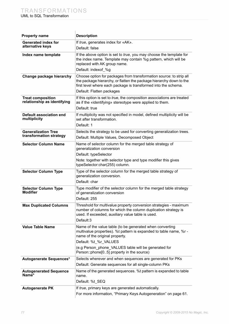
77 Copyright © 2009-2015 No Magic, Inc..
TRANSFORMATIONSUML to SQL Transformation
Generated index for alternative keys
If true, generates index for «AK».Default: false
Index name template If the above option is set to true, you may choose the template for the index name. Template may contain %g pattern, which will be replaced with AK group name.Default: indexof_%g
Change package hierarchy Choose option for packages from transformation source: to strip all the package hierarchy, or flatten the package hierarchy down to the first level where each package is transformed into the schema.Default: Flatten packages
Treat composition relationship as identifying
If this option is set to true, the composition associations are treated as if the «identifying» stereotype were applied to them.Default: true
Default association end multiplicity
If multiplicity was not specified in model, defined multiplicity will be set after transformation.Default: 1
Generalization Tree transformation strategy
Selects the strategy to be used for converting generalization trees.Default: Multiple Values, Decomposed Object
Selector Column Name Name of selector column for the merged table strategy of generalization conversionDefault: typeSelectorNote: together with selector type and type modifier this gives typeSelector:char(255) column.
Selector Column Type Type of the selector column for the merged table strategy of generalization conversion.Default: char
Selector Column Type Modifier
Type modifier of the selector column for the merged table strategy of generalization conversionDefault: 255
Max Duplicated Columns Threshold for multivalue property conversion strategies - maximum number of columns for which the column duplication strategy is used. If exceeded, auxiliary value table is used.Default:3
Value Table Name Name of the value table (to be generated when converting multivalue properties). %t pattern is expanded to table name, %r - name of the original property.Default: %t_%r_VALUES(e.g Person_phone_VALUES table will be generated for Person::phone[0..5] property in the source)
Autogenerate Sequences* Selects wherever and when sequences are generated for PKsDefault: Generate sequences for all single-column PKs
Autogenerated Sequence Name*
Name of the generated sequences. %t pattern is expanded to table name.Default: %t_SEQ
Autogenerate PK If true, primary keys are generated automatically.For more information, “Primary Keys Autogeneration” on page 61.
Property name Description

78 Copyright © 2009-2015 No Magic, Inc..
TRANSFORMATIONSER to SQL (Generic / Oracle) Transformations
* - These properties are available only for UML to SQL (Oracle) transformation.
ER to SQL (Generic / Oracle) TransformationsBoth generic and Oracle transformation flavors are very similar, so they will be described together. Furthermore, these transformations are based on and very similar to the UML to SQL(Generic / Oracle) transformations with several extensions, relevant to ER modeling.
Hence this chapter only describes this extended behavior of ER to SQL(Generic / Oracle) transformation. To see the full transformation feature set (which includes conversion of many-to-many relationships into an intermediate table, three different methods of transforming generalizations into table layouts, autogenerating primary keys, unique constraints and indexes, generating additional tables for multivalue attributes, type remapping between UML and database worlds, sequence generation, and package hierarchy flattening), please, see “UML to SQL Transformation” on page 60.
Identifying Relationships
Identifying relationships are transformed in the same way as in the UML to SQL transformation, that is, the foreign key of the transformation gets to be included into the primary key of the dependent entity (the one at the multiple end of the relationship). The difference in ER to SQL transformation case is that the ER model eliminates guessing, which relationships are identifying and which ones are not. UML to SQL transformation guesses, which UML associations should be identifying, by using a heuristic method - composition associations
Enumeration transformation strategy
For more information, see “Conversion of Enumerations” on page 67.
Expand datatypes For more information, see “Conversion of DataTypes” on page 64.
Expanded datatype column name template
For more information, see “Conversion of DataTypes” on page 64.
Name conversion rules One or more rules for element name conversion.For more information, see “Naming of Transformed Elements” on page 69.
FK name template An FK name template definition. You can use specific names and patterns, such as %t (a table name) or %r (a relationship role).
For more information, see “Conversion of Associations” on page 61.
Elements exclusion rules One or more rules for elements’ exclusion from the transformation.For more information, see “Excluding elements from transformation” on page 72.
Allow HTML in comments If true, SQL comments in DDL script retain HTML formatting information.For more information, see “Transforming documentation” on page 71.
NOTE Please note that the SQL model, produced by the transformation, is usually not optimal (e.g. all the generalizations are transformed using the same chosen strategy, while usually different strategies are chosen for each particular case - at the discretion of DBA). Hence it is frequently advisable to refine / edit the pro-duced model after the transformation.
Property name Description

79 Copyright © 2009-2015 No Magic, Inc..
TRANSFORMATIONSER to SQL (Generic / Oracle) Transformations
are treated as identifying (this heuristic is controlled by the Treat compositions as identifying transformation property). In ER models, identifying relationships are explicitly marked as such, hence there is no need to guess (“Identifying Relationships and Dependent Entities” on page 9 specifies how identifying relationships are modeled).
Key Transformation
Keys in ER models are transformed into constraints in a DDL model.
These are the rules for key transformations into DDL constraints:
1. The Primary key of the entity in the ER model is transformed into a primary key constraint in the SQL model.
2. The Alternative keys of the entities in the ER model are transformed into unique constraints in the SQL model.
3. The Inversion entries of the entities in the ER model are transformed into indexes in the SQL model.
4. If key or entry in ER model has a name (identifier tag), this information is preserved in the SQL model. The corresponding key / index will also have a name in the SQL model.
Lets review an example of key modeling, which has been described in “Key Modeling” on page 13. After the transformation, the three entities of the ER model are transformed into the three tables of the SQL model respectively.
Figure 41 -- TBD Screenshot Example of key transformation results
Virtual Entity Transformation
Virtual entities of ER models can be transformed into different elements of SQL models:
80 Copyright © 2009-2015 No Magic, Inc..
TRANSFORMATIONSSQL to UML Transformation
• Tables (just as ordinary, non-virtual entities).
• SQL views (ER to SQL(Oracle) transformation has an additional choice of simple views or materialized views).
The choice is controlled by the Virtual Entities Transformed To transformation property.
Tracing between Data Model Layers
After the transformation, a relationship is established between the logical data model layer, which is represented by the ER model, and the physical data model layer, which is represented by a SQL model respectively. It is possible to navigate between the connected elements in the forward (ER -> SQL) and backward (SQL -> ER) directions using the dedicated submenu - Go To - on the element’s shortcut menu.
To go to the corresponding element in the forward direction
1. Right-click the element.2. On it’s shortcut menu, click Go To > Traceability > Model Transformations > Transformed
To.
To go to the corresponding element in the backward direction
1. Right-click the element.2. On it’s shortcut menu, click Go To > Traceability > Model Transformations > Transformed
From.
The same tracing information is visible in the element’s Specification window and Properties panel under the Traceability tab. This information is also reflected in the Entity-Relationship and SQL Report using navigable references between the report section. Traceability information can also be depicted in a relation map or in a tabular format using the capabilities of the custom dependency matrix feature.
SQL to UML TransformationThe SQL models and diagrams will be transformed into the platform-independent UML models and UML class diagrams. SQL to UML transformation can be applied to SQL models of any database flavor.
Type Mapping
If there are types specified in the SQL model for elements, after transformation SQL types should be converted to UML types. Because of that, there is a type mapping from SQL types to UML types.
Mapping rules are based on dependencies, which contains the SQL to UML Type Map profile. This profile is automatically attached, when SQL to UML transformation is performed.
Transformation Results
The SQL stereotypes are discarded from tables, views, fields, and associations (except the PK stereotype).
Views are discarded in transformed class diagram.
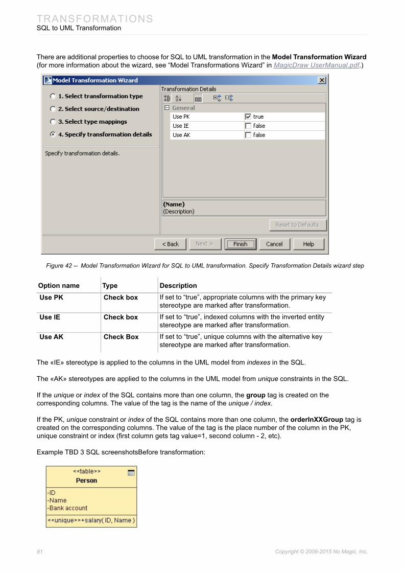
81 Copyright © 2009-2015 No Magic, Inc..
TRANSFORMATIONSSQL to UML Transformation
There are additional properties to choose for SQL to UML transformation in the Model Transformation Wizard (for more information about the wizard, see “Model Transformations Wizard” in MagicDraw UserManual.pdf.)
Figure 42 -- Model Transformation Wizard for SQL to UML transformation. Specify Transformation Details wizard step
The «IE» stereotype is applied to the columns in the UML model from indexes in the SQL.
The «AK» stereotypes are applied to the columns in the UML model from unique constraints in the SQL.
If the unique or index of the SQL contains more than one column, the group tag is created on the corresponding columns. The value of the tag is the name of the unique / index.
If the PK, unique constraint or index of the SQL contains more than one column, the orderInXXGroup tag is created on the corresponding columns. The value of the tag is the place number of the column in the PK, unique constraint or index (first column gets tag value=1, second column - 2, etc).
Example TBD 3 SQL screenshotsBefore transformation:
Option name Type DescriptionUse PK Check box If set to “true”, appropriate columns with the primary key
stereotype are marked after transformation.
Use IE Check box If set to “true”, indexed columns with the inverted entity stereotype are marked after transformation.
Use AK Check Box If set to “true”, unique columns with the alternative key stereotype are marked after transformation.
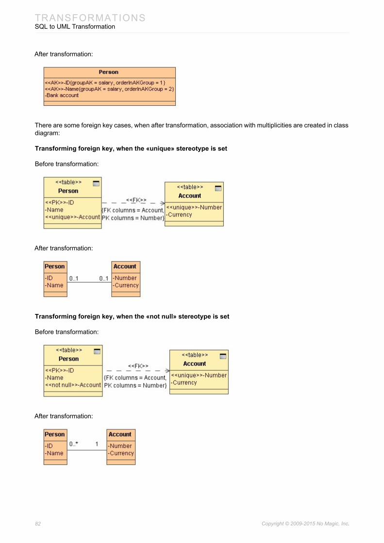
82 Copyright © 2009-2015 No Magic, Inc..
TRANSFORMATIONSSQL to UML Transformation
After transformation:
There are some foreign key cases, when after transformation, association with multiplicities are created in class diagram:
Transforming foreign key, when the «unique» stereotype is set
Before transformation:
After transformation:
Transforming foreign key, when the «not null» stereotype is set
Before transformation:
After transformation:
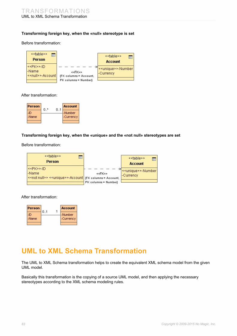
83 Copyright © 2009-2015 No Magic, Inc..
TRANSFORMATIONSUML to XML Schema Transformation
Transforming foreign key, when the «null» stereotype is set
Before transformation:
After transformation:
Transforming foreign key, when the «unique» and the «not null» stereotypes are set
Before transformation:
After transformation:
UML to XML Schema TransformationThe UML to XML Schema transformation helps to create the equivalent XML schema model from the given UML model.
Basically this transformation is the copying of a source UML model, and then applying the necessary stereotypes according to the XML schema modeling rules.

84 Copyright © 2009-2015 No Magic, Inc..
TRANSFORMATIONSUML to XML Schema Transformation
Type Mapping
This type map stores mapping between primitive UML data types and primitive XML Schema data types.
Figure 43 -- UML to XML schema type map (1)
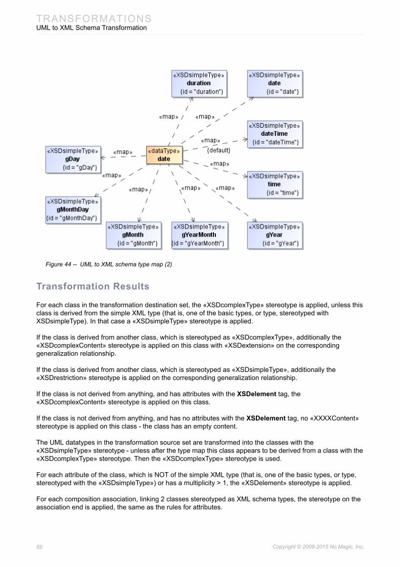
85 Copyright © 2009-2015 No Magic, Inc..
TRANSFORMATIONSUML to XML Schema Transformation
Figure 44 -- UML to XML schema type map (2)
Transformation Results
For each class in the transformation destination set, the «XSDcomplexType» stereotype is applied, unless this class is derived from the simple XML type (that is, one of the basic types, or type, stereotyped with XSDsimpleType). In that case a «XSDsimpleType» stereotype is applied.
If the class is derived from another class, which is stereotyped as «XSDcomplexType», additionally the «XSDcomplexContent» stereotype is applied on this class with «XSDextension» on the corresponding generalization relationship.
If the class is derived from another class, which is stereotyped as «XSDsimpleType», additionally the «XSDrestriction» stereotype is applied on the corresponding generalization relationship.
If the class is not derived from anything, and has attributes with the XSDelement tag, the «XSDcomplexContent» stereotype is applied on this class.
If the class is not derived from anything, and has no attributes with the XSDelement tag, no «XXXXContent» stereotype is applied on this class - the class has an empty content.
The UML datatypes in the transformation source set are transformed into the classes with the «XSDsimpleType» stereotype - unless after the type map this class appears to be derived from a class with the «XSDcomplexType» stereotype. Then the «XSDcomplexType» stereotype is used.
For each attribute of the class, which is NOT of the simple XML type (that is, one of the basic types, or type, stereotyped with the «XSDsimpleType») or has a multiplicity > 1, the «XSDelement» stereotype is applied.
For each composition association, linking 2 classes stereotyped as XML schema types, the stereotype on the association end is applied, the same as the rules for attributes.
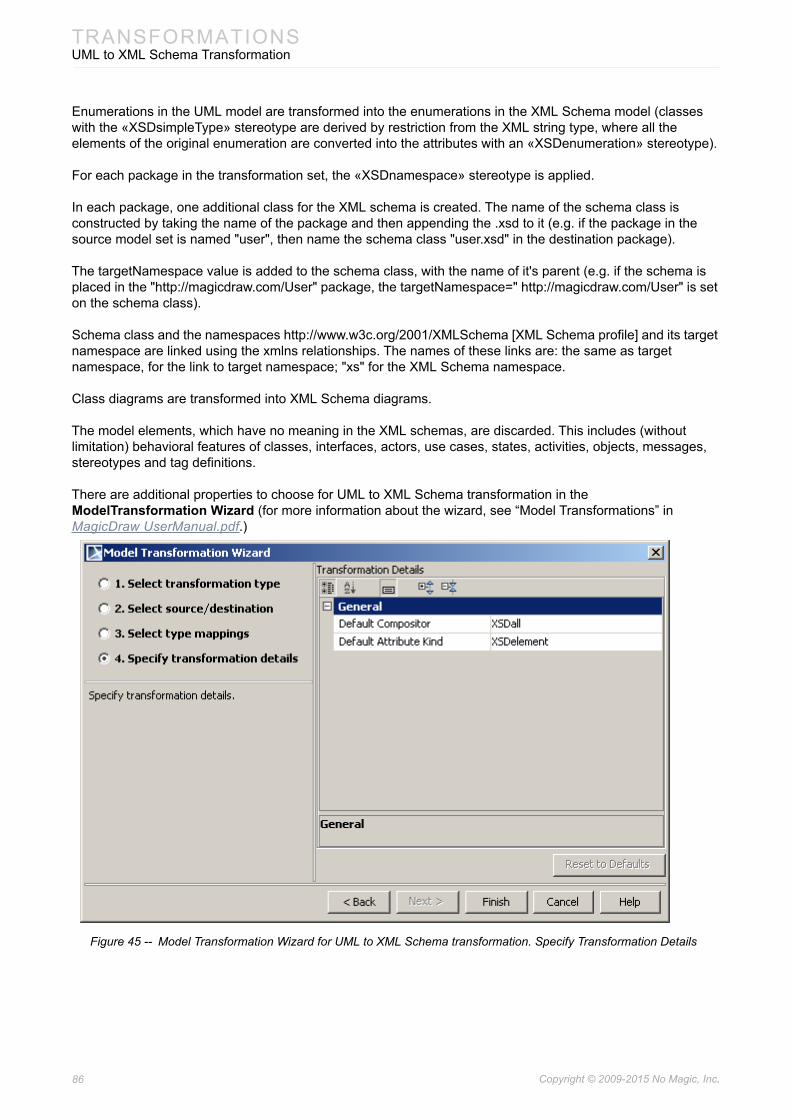
86 Copyright © 2009-2015 No Magic, Inc..
TRANSFORMATIONSUML to XML Schema Transformation
Enumerations in the UML model are transformed into the enumerations in the XML Schema model (classes with the «XSDsimpleType» stereotype are derived by restriction from the XML string type, where all the elements of the original enumeration are converted into the attributes with an «XSDenumeration» stereotype).
For each package in the transformation set, the «XSDnamespace» stereotype is applied.
In each package, one additional class for the XML schema is created. The name of the schema class is constructed by taking the name of the package and then appending the .xsd to it (e.g. if the package in the source model set is named "user", then name the schema class "user.xsd" in the destination package).
The targetNamespace value is added to the schema class, with the name of it's parent (e.g. if the schema is placed in the "http://magicdraw.com/User" package, the targetNamespace=" http://magicdraw.com/User" is set on the schema class).
Schema class and the namespaces http://www.w3c.org/2001/XMLSchema [XML Schema profile] and its target namespace are linked using the xmlns relationships. The names of these links are: the same as target namespace, for the link to target namespace; "xs" for the XML Schema namespace.
Class diagrams are transformed into XML Schema diagrams.
The model elements, which have no meaning in the XML schemas, are discarded. This includes (without limitation) behavioral features of classes, interfaces, actors, use cases, states, activities, objects, messages, stereotypes and tag definitions.
There are additional properties to choose for UML to XML Schema transformation in the ModelTransformation Wizard (for more information about the wizard, see “Model Transformations” in MagicDraw UserManual.pdf.)
Figure 45 -- Model Transformation Wizard for UML to XML Schema transformation. Specify Transformation Details

87 Copyright © 2009-2015 No Magic, Inc..
TRANSFORMATIONSXML Schema to UML Transformation
XML Schema to UML TransformationThe XML Schema to UML transformation helps to extract the abstract UML model from the XML schema model.
Type Mapping
Type maps store mapping between primitive UML data types and primitive XML Schema data types, the same applies for UML to XML Schema Transformation just in reversed order. For XML Schema to UML element type mapping diagram, see “Type Mapping” on page 84.
Transformation Results
The XML Schema diagrams are transformed to the Class diagrams.
Unnecessary stereotypes (XSDxxxx) are discarded from the classes.
Attributes of the classes are gathered if they were spread into several different classes.
Attributes of the classes may be realized as associations. In this case the main class gathers all the associations of the members.
The same principle is applied when elements are in a group, shared by two or more classes. Elements (attributes) are copied into both destination classes.
The attributes with the «XSDgroupRef» stereotype are treated as if the group relationship has been drawn and transformed accordingly - discarded in the UML model, and the group content (elements / attributes) placed in their place.
Simple XML schema types (classes with the «XSDsimpleType» stereotype), which after copying and type remap happen to be derived from any data type (UML DataType) or not derived from anything and are transformed into the UML data types.
Simple XML schema types, which are derived by restriction from string and are restricted by enumerating string values and are converted into enumerations in the UML diagrams.
The classes with the «XSDschema» stereotype are not copied into a destination model.
The «XDSkey», «XSDkeyref», and «XSDunique» stereotyped attributes are not copied into a destination model.
Option name Type DescriptionDefault Compositor
Combo box Possible choices: XSDall, XSDchoice, XSDsequenceDetermines element grouping in complex types of XML Schema.Default: XSDall
Default Attribute Kind
Combo box Determines to what attribute kind, XSDelement or XSDattribute UML attribute will be mapped.Default: XSDelement

88 Copyright © 2009-2015 No Magic, Inc..
TRANSFORMATIONSXML Schema to UML Transformation
The «XDSany», «XSDanyAttribute» stereotyped attributes are not copied into a destination model.
The «XDSnotation» stereotyped attributes are not copied into a destination model.
The «XDSlength», «XDSminLength», «XDSmaxLength», «XSDpattern», «XSDfractionDigits», «XSDtotalDigits», «XDSmaxExclusive», «XDSmaxInclusive», «XDSminExclusive», and «XDSminInclusive» stereotyped attributes are not copied into a destination model.
The XML schemas (classes with the «XSDschema» stereotype) should not be transformed, but they may contain inner classes (anonymous types of schema elements). These inner classes are transformed using usual rules for UML type transformation - as if they were not inner classes but normal XML schema types.
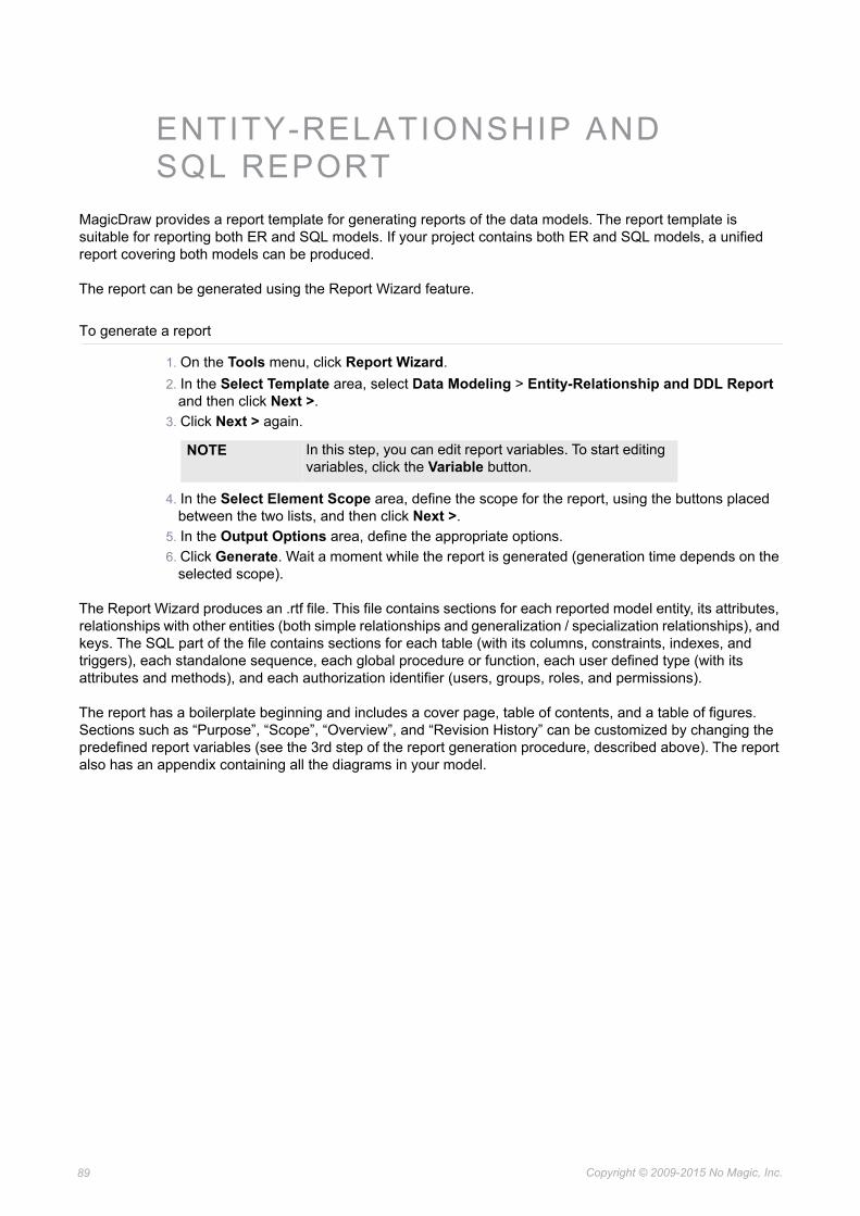
Copyright © 2009-2015 No Magic, Inc.89
ENTITY-RELATIONSHIP AND SQL REPORT
MagicDraw provides a report template for generating reports of the data models. The report template is suitable for reporting both ER and SQL models. If your project contains both ER and SQL models, a unified report covering both models can be produced.
The report can be generated using the Report Wizard feature.
To generate a report
1. On the Tools menu, click Report Wizard.2. In the Select Template area, select Data Modeling > Entity-Relationship and DDL Report
and then click Next >.3. Click Next > again.
4. In the Select Element Scope area, define the scope for the report, using the buttons placed between the two lists, and then click Next >.
5. In the Output Options area, define the appropriate options.6. Click Generate. Wait a moment while the report is generated (generation time depends on the
selected scope).
The Report Wizard produces an .rtf file. This file contains sections for each reported model entity, its attributes, relationships with other entities (both simple relationships and generalization / specialization relationships), and keys. The SQL part of the file contains sections for each table (with its columns, constraints, indexes, and triggers), each standalone sequence, each global procedure or function, each user defined type (with its attributes and methods), and each authorization identifier (users, groups, roles, and permissions).
The report has a boilerplate beginning and includes a cover page, table of contents, and a table of figures. Sections such as “Purpose”, “Scope”, “Overview”, and “Revision History” can be customized by changing the predefined report variables (see the 3rd step of the report generation procedure, described above). The report also has an appendix containing all the diagrams in your model.
NOTE In this step, you can edit report variables. To start editing variables, click the Variable button.

90 Copyright © 2009-2015 No Magic, Inc..
ENTITY-RELATIONSHIP AND SQL REPORT
If the model contains both ER and SQL models and is linked by traceability references, the report will link (with active references) the appropriate report sections of entities and tables that are traceable in the model.
Figure 46 -- Fragment of ER model report example
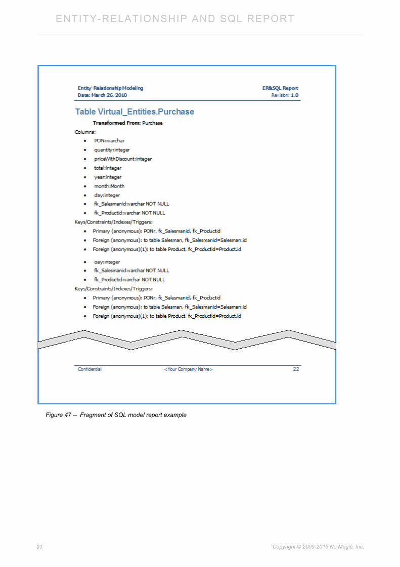
91 Copyright © 2009-2015 No Magic, Inc..
ENTITY-RELATIONSHIP AND SQL REPORT
Figure 47 -- Fragment of SQL model report example
Copyright © 2009-2015 No Magic, Inc.92
XML SCHEMAS
IntroductionReference: http://www.w3.org/TR/xmlschema-2/

93 Copyright © 2009-2015 No Magic, Inc..
XML SCHEMASXML Schema Mapping to UML Elements
XML Schema Mapping to UML Elements
Defined stereotypes
Stereotype name Base Stereotype
Applies on Defined TagDefinitions
XSDcomponent Class
Attribute
AssociationEnd
Binding
Generalization
Comment
Component
id – string
Details: The base and abstract stereotype for all XML Schema stereotypes used in UML profile
XSDattribute XSDcomponent Attribute fixed – some fixed element value
form – (qualified | unqualified)
refString – string representation of reference to other attribute.
ref – actual reference to other attribute
use – (optional | prohibited | required) : optional
XSDelement XSDcomponent Attribute
AssociationEnd
abstract – (true | false)
block - (extension | restriction | substitution)
final - (extension | restriction)
fixed – some fixed element value
form - (qualified | unqualified)
nillable – (true | false)
refString – string representation of reference to other attribute.
ref – actual reference to other attribute
substitutionGroup – actual reference to UML ModelElement
substitutionGroupString – string representation of substitution group
key_unique_keyRef – a list of referenced UML Attributes
sequenceOrder – a number in sequence order
XSDcomplexType XSDcomponent Class block – (extension | restriction)
final – (extension | restriction)
mixed – (true | false)
XSDsimpleContent
Class simpleContentId – string
XSDcomplexContent
Class complexContentId – string
complexContentMixed
XSDgroup XSDcomponent Class

94 Copyright © 2009-2015 No Magic, Inc..
XML SCHEMASXML Schema Mapping to UML Elements
XSDgroupRef XSDcomponent Attribute
AssociationEnd
sequenceOrder – a number in sequence order
XSDall Class allId – string
maxOccurs
minOccurs
XSDchoice Class choiceId – string
maxOccurs
minOccurs
sequenceOrder – a number in sequence order
XSDsequence Class sequenceId – string
maxOccurs
minOccurs
sequenceOrder – a number in sequence order
XSDrestriction XSDcomponent Generalization
XSDextension XSDcomponent Generalization
XSDattributeGroup
XSDcomponent Class
XSDsimpleType XSDcomponent Class final - (#all | (list | union | restriction))
XSDlist XSDcomponent Class listId - string
XSDunion XSDcomponent Class unionId - string
XSDannotation XSDcomponent Comment appInfoSource
appInfoContent
source
xml:lang
XSDany XSDcomponent Attribute namespace – string
processContents - (lax | skip | strict); default strict
sequenceOrder – a number in sequence order
XSDanyAttribute XSDcomponent Attribute namespace – string
processContents - (lax | skip | strict); default strict
XSDschema XSDcomponent Class attributeFormDefault
blockDefault
elementFormDefault
finalDefault
targetNamespace – reference to some ModelPackage
version
xml:lang
Stereotype name Base Stereotype
Applies on Defined TagDefinitions

95 Copyright © 2009-2015 No Magic, Inc..
XML SCHEMASXML Schema Mapping to UML Elements
attribute• XML schema attribute maps to UML Attribute with stereotype XSDattribute.
• default maps to initial UML Attribute or AssociationEnd value.
• annotation – to UML Attribute or AssociationEnd documentation.
• name – to UML Attribute or AssociationEnd name.
• type or content simpleType – to UML Attribute or AssociationEnd type.
XSDnotation XSDcomponent Attribute public
system
XSDredefine XSDcomponent Class
XSDimport XSDcomponent
«import»
Permision schemaLocation
XSDinclude XSDcomponent Component
XSDminExclusive XSDcomponent Attribute fixed = boolean : false
XSDminInclusive XSDcomponent Attribute fixed = boolean : false
XSDmaxExclusive
XSDcomponent Attribute fixed = boolean : false
XSDmaxInclusive XSDcomponent Attribute fixed = boolean : false
XSDtotalDigits XSDcomponent Attribute fixed = boolean : false
XSDfractionDigits XSDcomponent Attribute fixed = boolean : false
XSDlength XSDcomponent Attribute fixed = boolean : false
XSDminLength XSDcomponent Attribute fixed = boolean : false
XSDmaxLength XSDcomponent Attribute fixed = boolean : false
XSDwhiteSpace XSDcomponent Attribute fixed = boolean : false
value
XSDpattern XSDcomponent Attribute
XSDenumeration XSDcomponent Attribute
XSDunique Attribute selector
field
XSDkey Attribute selector
field
XSDkeyref Attribute selector
field
refer – UML Attribute
referString - String
XSDnamespace ModelPackage
xmlns Permission
Stereotype name Base Stereotype
Applies on Defined TagDefinitions
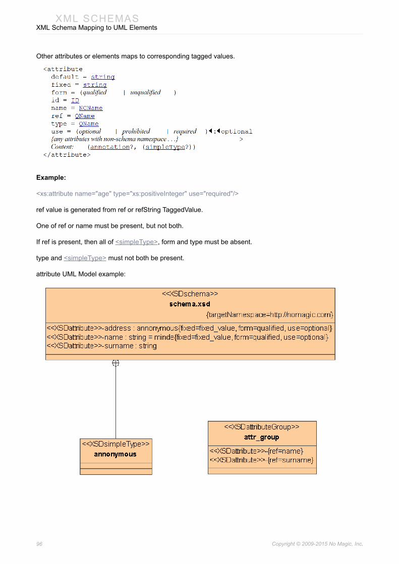
96 Copyright © 2009-2015 No Magic, Inc..
XML SCHEMASXML Schema Mapping to UML Elements
Other attributes or elements maps to corresponding tagged values.
Example:
<xs:attribute name="age" type="xs:positiveInteger" use="required"/>
ref value is generated from ref or refString TaggedValue.
One of ref or name must be present, but not both.
If ref is present, then all of <simpleType>, form and type must be absent.
type and <simpleType> must not both be present.
attribute UML Model example:

97 Copyright © 2009-2015 No Magic, Inc..
XML SCHEMASXML Schema Mapping to UML Elements
<xs:schema xmlns:nm = "http://nomagic.com" xmlns:xs = "http://www.w3.org/2001/XMLSchema" targetNamespace = "http://nomagic.com"
element
Maps to UML Attribute or UML AssociationEnd with stereotype XSDelement.
• annotation – to UML Attribute or UML AssociationEnd documentation.
• default - to initial UML Attribute or UML AssociationEnd value.
• maxOccurs - to multiplicity upper range. Value unbounded maps to asterisk in UML.
• minOccurs – to multiplicity lower range.
• name – to UML Attribute or UML AssociationEnd name.
• type or content (simpleType | complexType) – to UML Attribute or UML AssociationEnd type.
Other properties maps to corresponding tagged values.
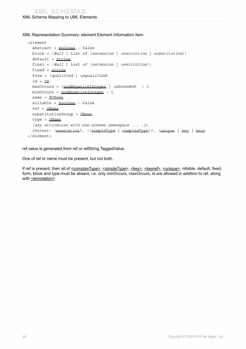
98 Copyright © 2009-2015 No Magic, Inc..
XML SCHEMASXML Schema Mapping to UML Elements
XML Representation Summary: element Element Information Item
ref value is generated from ref or refString TaggedValue.
One of ref or name must be present, but not both.
If ref is present, then all of <complexType>, <simpleType>, <key>, <keyref>, <unique>, nillable, default, fixed, form, block and type must be absent, i.e. only minOccurs, maxOccurs, id are allowed in addition to ref, along with <annotation>

99 Copyright © 2009-2015 No Magic, Inc..
XML SCHEMASXML Schema Mapping to UML Elements
Example:
element UML Model example:
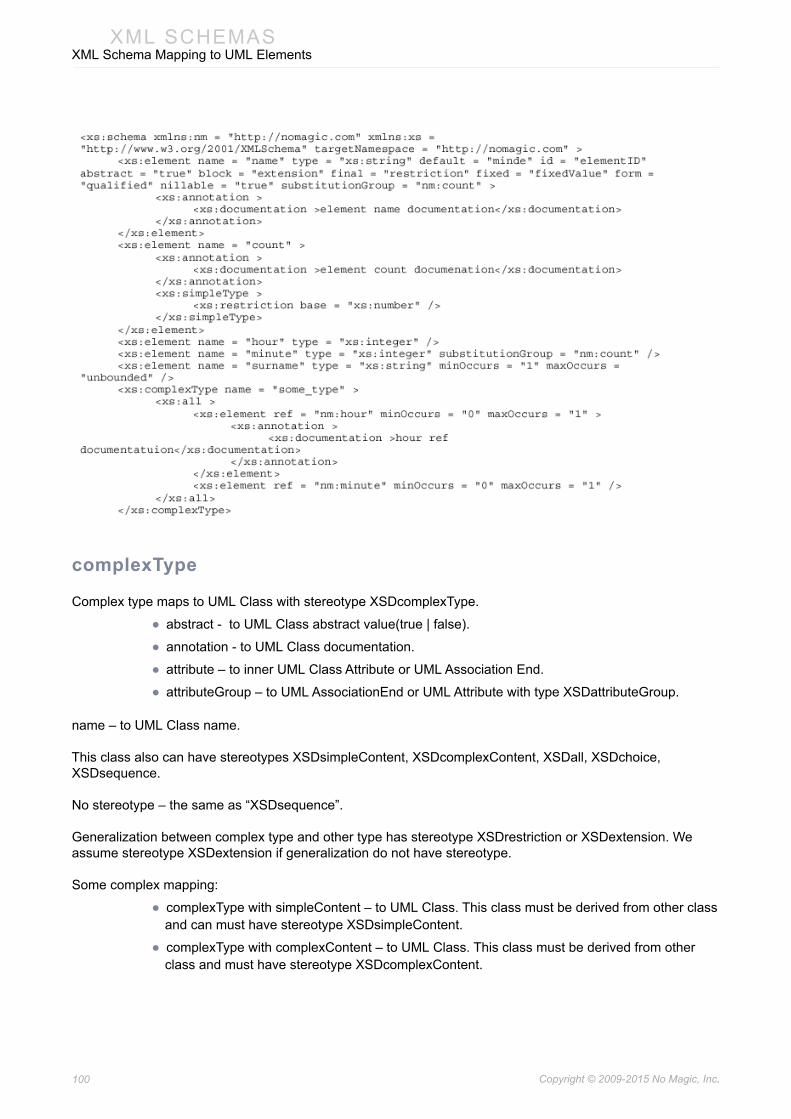
100 Copyright © 2009-2015 No Magic, Inc..
XML SCHEMASXML Schema Mapping to UML Elements
complexType
Complex type maps to UML Class with stereotype XSDcomplexType.
• abstract - to UML Class abstract value(true | false).
• annotation - to UML Class documentation.
• attribute – to inner UML Class Attribute or UML Association End.
• attributeGroup – to UML AssociationEnd or UML Attribute with type XSDattributeGroup.
name – to UML Class name.
This class also can have stereotypes XSDsimpleContent, XSDcomplexContent, XSDall, XSDchoice, XSDsequence.
No stereotype – the same as “XSDsequence”.
Generalization between complex type and other type has stereotype XSDrestriction or XSDextension. We assume stereotype XSDextension if generalization do not have stereotype.
Some complex mapping:
• complexType with simpleContent – to UML Class. This class must be derived from other class and can must have stereotype XSDsimpleContent.
• complexType with complexContent – to UML Class. This class must be derived from other class and must have stereotype XSDcomplexContent.

101 Copyright © 2009-2015 No Magic, Inc..
XML SCHEMASXML Schema Mapping to UML Elements
complexType with group, all, choice or sequence – to UML class with appropriate stereotype.
When the <simpleContent> alternative is chosen, the following elements are relevant, and the remaining property mappings are as below. Note that either <restriction> or <extension> must be chosen as the content of <simpleContent>
When the <complexContent> alternative is chosen, the following elements are relevant (as are the <attributeGroup> and <anyAttribute> elements, not repeated here), and the additional property mappings are as below. Note that either <restriction> or <extension> must be chosen as the content of <complexContent>, but their content models are different in this case from the case above when they occur as children of <simpleContent>.
The property mappings below are also used in the case where the third alternative (neither <simpleContent> nor <complexContent>) is chosen. This case is understood as shorthand for complex content restricting the ur-type definition, and the details of the mappings should be modified as necessary.
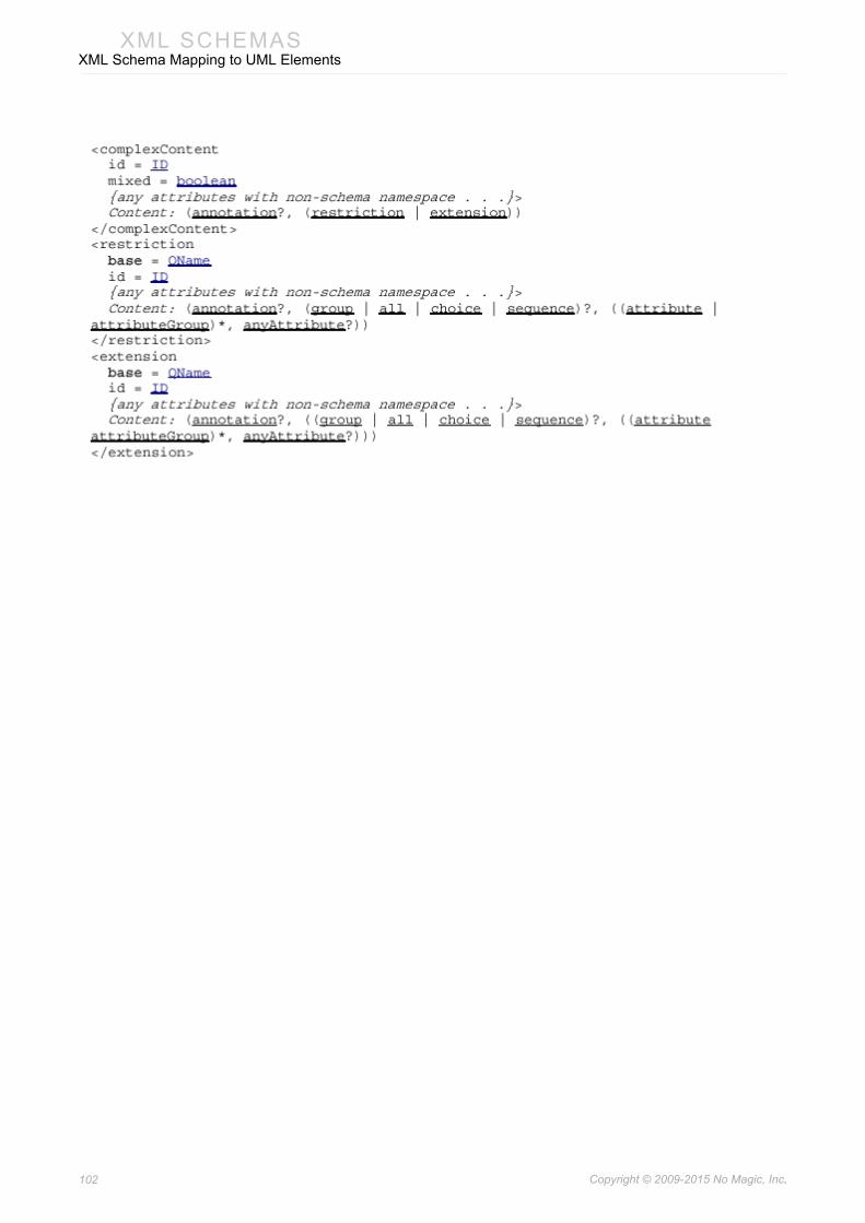
102 Copyright © 2009-2015 No Magic, Inc..
XML SCHEMASXML Schema Mapping to UML Elements

103 Copyright © 2009-2015 No Magic, Inc..
XML SCHEMASXML Schema Mapping to UML Elements
complexType UML Model example:

104 Copyright © 2009-2015 No Magic, Inc..
XML SCHEMASXML Schema Mapping to UML Elements
attributeGroup
attributeGroup maps to simple UML Class with stereotype XSDattributeGroup.
• name – to UML Class name
• annotation – to UML Class documentation
• attribute – to inner UML Attribute or AssociationEnd with XSDattribute
• stereotype.
• attributeGroup - inner attributeGroup always must be just reference. Such reference maps to Attribute or AssociationEnd with type of referenced attributeGroup. The opposite Association End kind must be aggregated and it must be navigable.
• anyAttribute – to inner UML Attribute with stereotype XSDanyAttribute.

105 Copyright © 2009-2015 No Magic, Inc..
XML SCHEMASXML Schema Mapping to UML Elements
If reference is generated, name is not generated.
When an <attributeGroup> appears as a daughter of <schema> or <redefine>, it corresponds to an attribute group definition as below. When it appears as a daughter of <complexType> or <attributeGroup>, it does not correspond to any component as such.
attributeGroup UML Model example:

106 Copyright © 2009-2015 No Magic, Inc..
XML SCHEMASXML Schema Mapping to UML Elements
simpleType
Maps to UML Class with stereotype XSDsimpleType.
Example:
The XML representation of a simple type definition.
restriction
To specify restriction generalization must be used between this class and super class. This generalization has or do not have XSDrestriction stereotype. Restriction id and annotation maps to Generalization properties.
In order to have inner simpleType element, parent of this Generalization must be inner Class of outer UML Class.
list
UML Class must have additional stereotype XSDlist.

107 Copyright © 2009-2015 No Magic, Inc..
XML SCHEMASXML Schema Mapping to UML Elements
Binding between this class and XSD:list must be provided.
“itemsType” maps to UML TemplateArgument from Binding.
union
UML Class must have additional stereotype XSDunion.
“memberTypes” and inner simpleTypes maps to several UML Generalizations between this simple type and members types.
In order to have inner simpleType element, parent of this Generalization must be inner Class of outer UML Class.
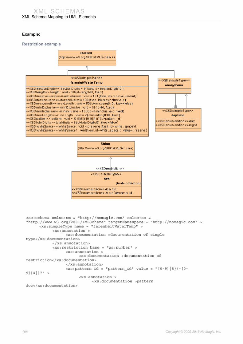
108 Copyright © 2009-2015 No Magic, Inc..
XML SCHEMASXML Schema Mapping to UML Elements
Example:
Restriction example

109 Copyright © 2009-2015 No Magic, Inc..
XML SCHEMASXML Schema Mapping to UML Elements

110 Copyright © 2009-2015 No Magic, Inc..
XML SCHEMASXML Schema Mapping to UML Elements
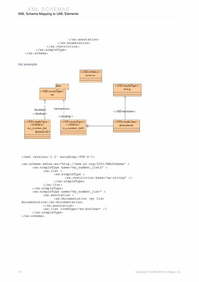
111 Copyright © 2009-2015 No Magic, Inc..
XML SCHEMASXML Schema Mapping to UML Elements
list example
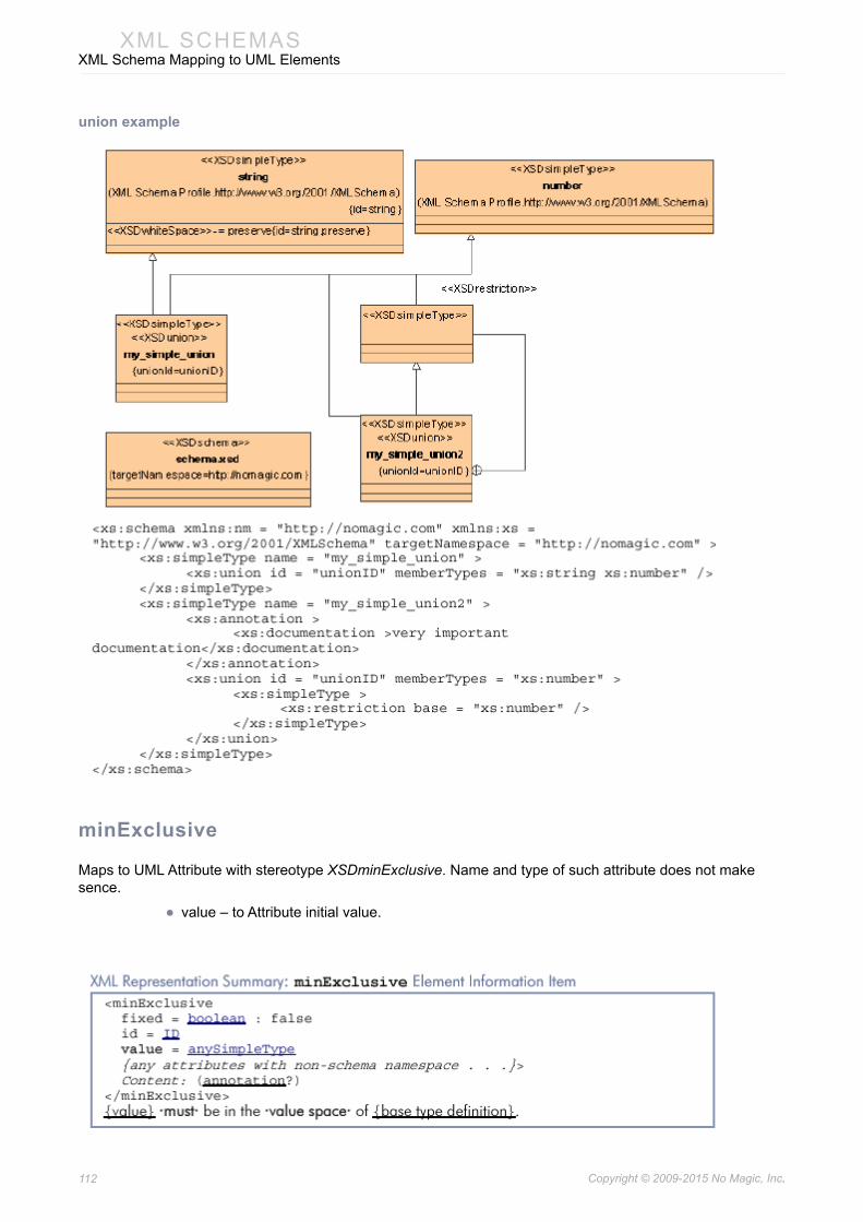
112 Copyright © 2009-2015 No Magic, Inc..
XML SCHEMASXML Schema Mapping to UML Elements
union example
minExclusive
Maps to UML Attribute with stereotype XSDminExclusive. Name and type of such attribute does not make sence.
• value – to Attribute initial value.
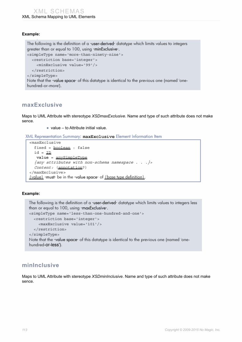
113 Copyright © 2009-2015 No Magic, Inc..
XML SCHEMASXML Schema Mapping to UML Elements
Example:
maxExclusive
Maps to UML Attribute with stereotype XSDmaxExclusive. Name and type of such attribute does not make sence.
• value – to Attribute initial value.
Example:
minInclusive
Maps to UML Attribute with stereotype XSDminInclusive. Name and type of such attribute does not make sence.

114 Copyright © 2009-2015 No Magic, Inc..
XML SCHEMASXML Schema Mapping to UML Elements
• value – to Attribute initial value.
Example:
maxInclusive
Maps to UML Attribute with stereotype XSDmaxInclusive. Name and type of such attribute does not make sence.
• value – to Attribute initial value.
Example:
totalDigits
Maps to UML Attribute with stereotype XSDtotalDigits. Name and type of such attribute does not make sence.

115 Copyright © 2009-2015 No Magic, Inc..
XML SCHEMASXML Schema Mapping to UML Elements
• value – to Attribute initial value.
Example
fractionDigits
Maps to UML Attribute with stereotype XSDfractionDigits. Name and type of such attribute does not make sence.
• value – to Attribute initial value.
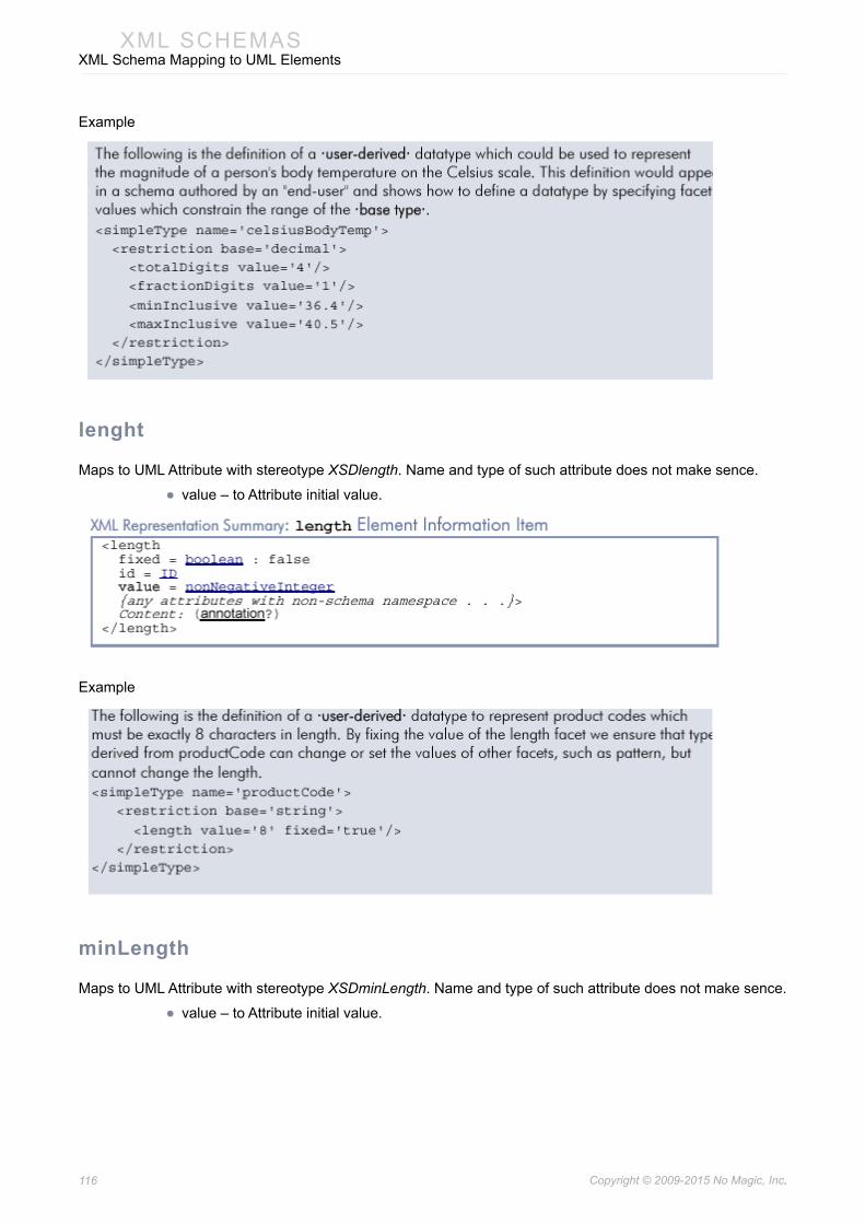
116 Copyright © 2009-2015 No Magic, Inc..
XML SCHEMASXML Schema Mapping to UML Elements
Example
lenght
Maps to UML Attribute with stereotype XSDlength. Name and type of such attribute does not make sence.
• value – to Attribute initial value.
Example
minLength
Maps to UML Attribute with stereotype XSDminLength. Name and type of such attribute does not make sence.
• value – to Attribute initial value.

117 Copyright © 2009-2015 No Magic, Inc..
XML SCHEMASXML Schema Mapping to UML Elements
Example
maxLength
Maps to UML Attribute with stereotype XSDmaxLength. Name and type of such attribute does not make sence.
• value – to Attribute initial value.
Example
whiteSpace
Maps to UML Attribute with stereotype XSDwhiteSpace. Name and type of such attribute does not make sence.
• value – to Attribute initial value.
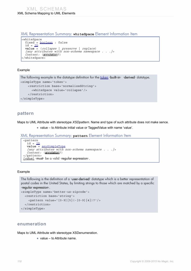
118 Copyright © 2009-2015 No Magic, Inc..
XML SCHEMASXML Schema Mapping to UML Elements
Example
pattern
Maps to UML Attribute with stereotype XSDpattern. Name and type of such attribute does not make sence.
• value – to Attribute initial value or TaggedValue with name ‘value’.
Example
enumeration
Maps to UML Attribute with stereotype XSDenumeration.
• value – to Attribute name.
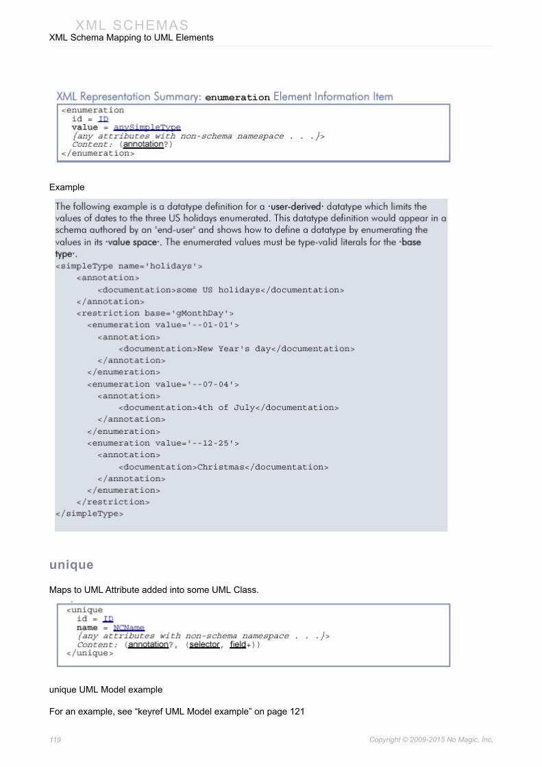
119 Copyright © 2009-2015 No Magic, Inc..
XML SCHEMASXML Schema Mapping to UML Elements
Example
unique
Maps to UML Attribute added into some UML Class.
unique UML Model example
For an example, see “keyref UML Model example” on page 121
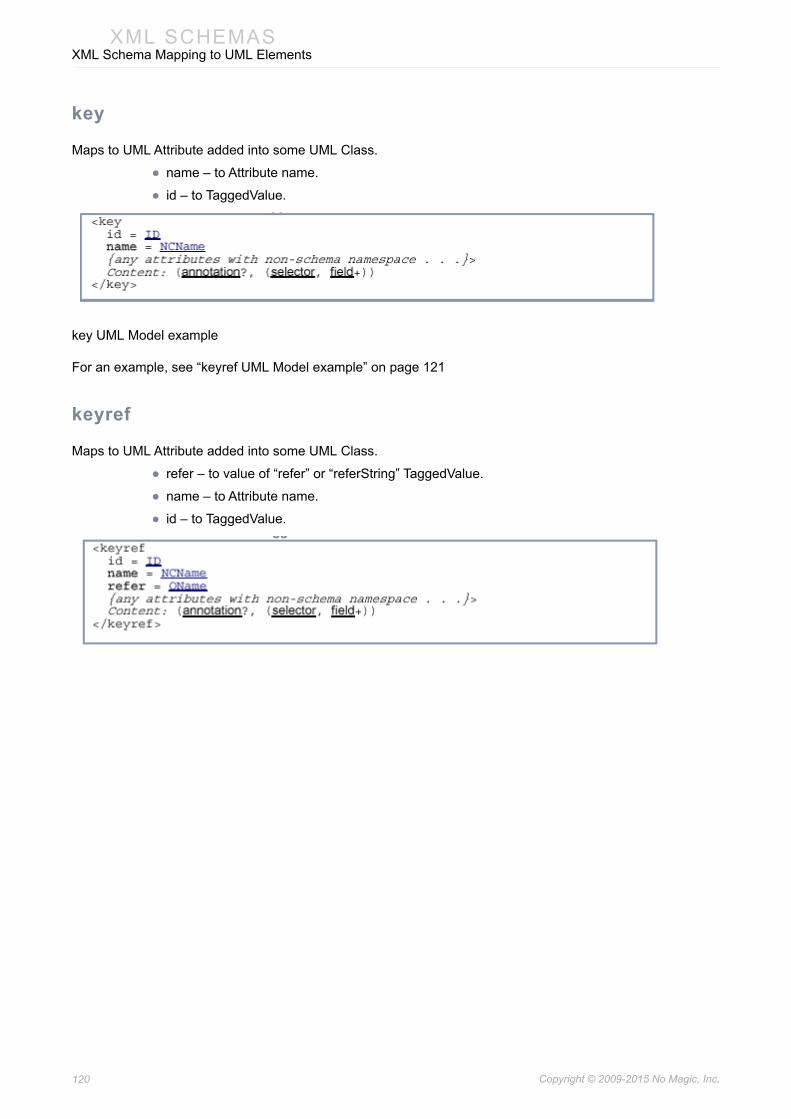
120 Copyright © 2009-2015 No Magic, Inc..
XML SCHEMASXML Schema Mapping to UML Elements
key
Maps to UML Attribute added into some UML Class.
• name – to Attribute name.
• id – to TaggedValue.
key UML Model example
For an example, see “keyref UML Model example” on page 121
keyref
Maps to UML Attribute added into some UML Class.
• refer – to value of “refer” or “referString” TaggedValue.
• name – to Attribute name.
• id – to TaggedValue.

121 Copyright © 2009-2015 No Magic, Inc..
XML SCHEMASXML Schema Mapping to UML Elements
keyref UML Model example
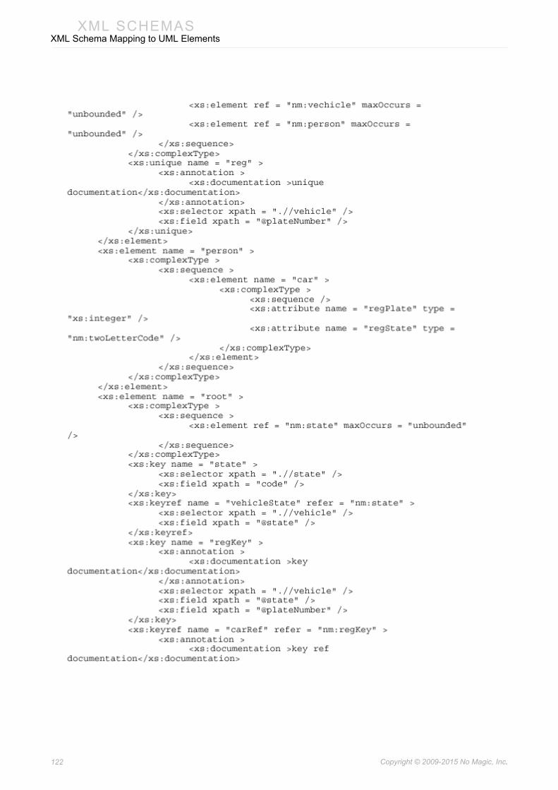
122 Copyright © 2009-2015 No Magic, Inc..
XML SCHEMASXML Schema Mapping to UML Elements

123 Copyright © 2009-2015 No Magic, Inc..
XML SCHEMASXML Schema Mapping to UML Elements
selector and field
Maps to UML TaggedValues named “selector” and “field” of UML Attribute representing key,keyRef or unique. “selector” tag has value representing “xpath” and “field” - list of valuesrepresenting field “xpath”. ID values shall be skipped and annotation documentation will beapplied to tagged value according to annotation rule (see:annotation). For field valuesannotation documentation shall be merged in one.
Example

124 Copyright © 2009-2015 No Magic, Inc..
XML SCHEMASXML Schema Mapping to UML Elements
XML representations for the three kinds of identity-constraint definitions
Example

125 Copyright © 2009-2015 No Magic, Inc..
XML SCHEMASXML Schema Mapping to UML Elements
A state element is defined, which contains a code child and some vehicle and person children. A vehicle in turn has a plateNumber attribute, which is an integer, and a state attribute. State's code s are a key for them within the document. Vehicle's plateNumber s are a key for them within states, and state and plateNumber is asserted to be a key for vehicle within the document as a whole. Furthermore, a person element has an empty car child, with regState and regPlate attributes, which are then asserted together to refer to vehicles via the carRef constraint. The requirement that a vehicle's state match its containing state's code is not expressed here.
selector and field UML Model example
For an example, see “keyref UML Model example” on page 121
annotation
Maps to UML Comment with or without stereotype XSDannotation.
Documentation’s content maps to UML Comment body(name).
“documentation” maps as UML comment:
• “content” value shall be comment name
• “xml:lang” value – tag “xml:lang” value
• source value – tag ”source” value
“appinfo” maps as tag value with name “appInfoSource”:
• “source” value will be tag value
• “content” will be documentation for tagged value
Appearing several annotation nodes on one element node, mapping shall be done in following way:
• “documentation” text shall be merged into one UML comment with merged content, but “content” and “xml:lang” tag values shall represent only first matched values
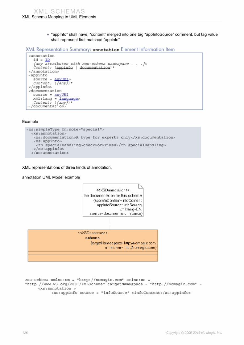
126 Copyright © 2009-2015 No Magic, Inc..
XML SCHEMASXML Schema Mapping to UML Elements
• “appInfo” shall have: “content” merged into one tag “appInfoSource” comment, but tag value shall represent first matched “appinfo”
Example
XML representations of three kinds of annotation.
annotation UML Model example
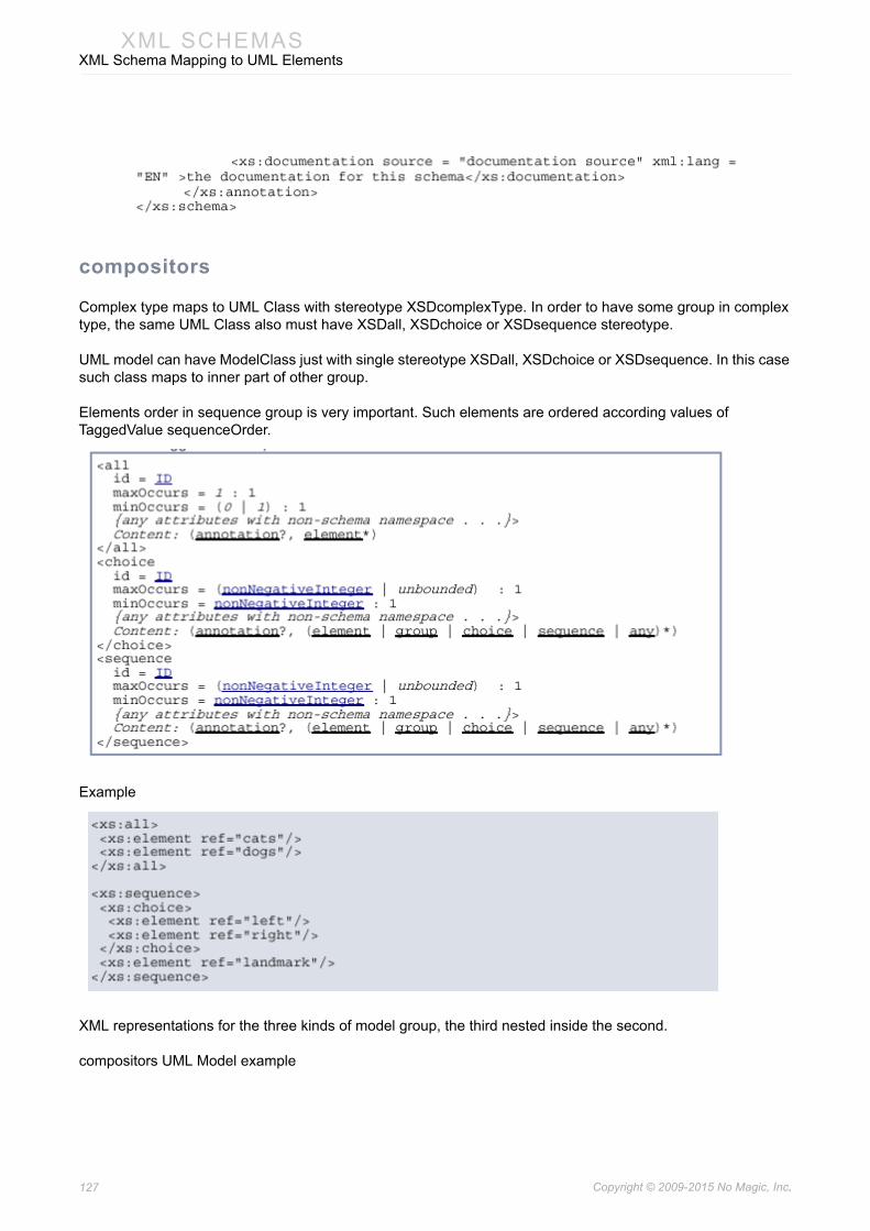
127 Copyright © 2009-2015 No Magic, Inc..
XML SCHEMASXML Schema Mapping to UML Elements
compositors
Complex type maps to UML Class with stereotype XSDcomplexType. In order to have some group in complex type, the same UML Class also must have XSDall, XSDchoice or XSDsequence stereotype.
UML model can have ModelClass just with single stereotype XSDall, XSDchoice or XSDsequence. In this case such class maps to inner part of other group.
Elements order in sequence group is very important. Such elements are ordered according values of TaggedValue sequenceOrder.
Example
XML representations for the three kinds of model group, the third nested inside the second.
compositors UML Model example

128 Copyright © 2009-2015 No Magic, Inc..
XML SCHEMASXML Schema Mapping to UML Elements
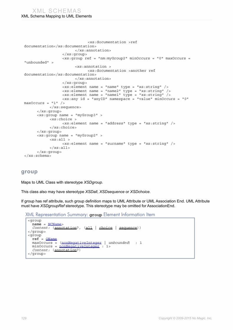
129 Copyright © 2009-2015 No Magic, Inc..
XML SCHEMASXML Schema Mapping to UML Elements
group
Maps to UML Class with stereotype XSDgroup.
This class also may have stereotype XSDall, XSDsequence or XSDchoice.
If group has ref attribute, such group definition maps to UML Attribute or UML Association End. UML Attribute must have XSDgroupRef stereotype. This stereotype may be omitted for AssociationEnd.

130 Copyright © 2009-2015 No Magic, Inc..
XML SCHEMASXML Schema Mapping to UML Elements
Example
group UML Model example
For an example, see “compositors UML Model example” on page 127
any and anyAttribute
Maps to UML Attribute with stereotype XSDany or XSDanyAttribute.
maxOccurs - to multiplicity upper range. Value unbounded maps to asterisk in UML.
minOccurs – to multiplicity lower range.
annotation maps to Attribute documentation
Other properties to TaggedValues.
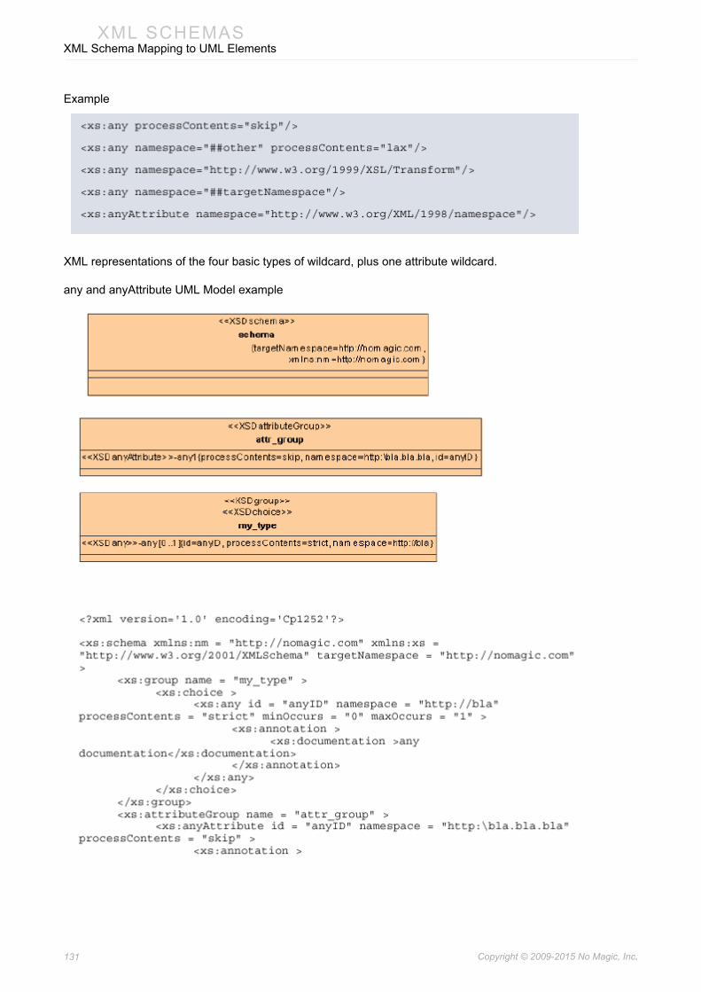
131 Copyright © 2009-2015 No Magic, Inc..
XML SCHEMASXML Schema Mapping to UML Elements
Example
XML representations of the four basic types of wildcard, plus one attribute wildcard.
any and anyAttribute UML Model example
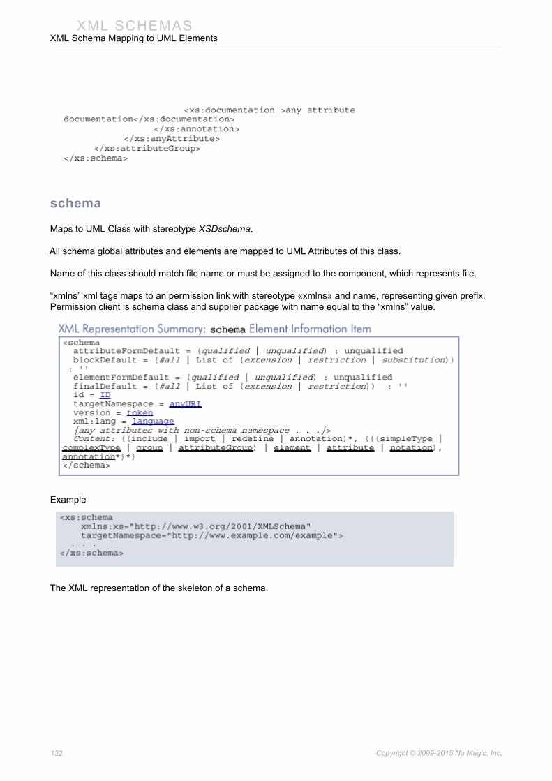
132 Copyright © 2009-2015 No Magic, Inc..
XML SCHEMASXML Schema Mapping to UML Elements
schema
Maps to UML Class with stereotype XSDschema.
All schema global attributes and elements are mapped to UML Attributes of this class.
Name of this class should match file name or must be assigned to the component, which represents file.
“xmlns” xml tags maps to an permission link with stereotype «xmlns» and name, representing given prefix. Permission client is schema class and supplier package with name equal to the “xmlns” value.
Example
The XML representation of the skeleton of a schema.

133 Copyright © 2009-2015 No Magic, Inc..
XML SCHEMASXML Schema Mapping to UML Elements
schema UML Model example
notation
Maps to UML Attribute with stereotype XSDnotation. This attribute must be added into UML class with stereotype XSDschema.
• name maps to UML Attribute name
• annotation maps to UML Attribute documentation.

134 Copyright © 2009-2015 No Magic, Inc..
XML SCHEMASXML Schema Mapping to UML Elements
Example
The XML representation of a notation declaration.
notation UML Model example
redefine
Maps to UML Class with stereotype XSDredefine. This class has inner UML Classes as redefined elements. Every redefined element must be derived from other UML class with stereotype XSDsimpleType, XSDcomplexType, XSDgroup, XSDattributeGroup. The name of this class shall match “schemaLocation” value.
If two “redefine” with the same schema location appears, they shall be merged to the one and the same class with a name “schemaLocation”.
Redefine Class must be inner class of XSDschema Class.
• annotation - to XSDredefine UML Class documentation
• schemaLocation – to XSDredefine UML Class name.
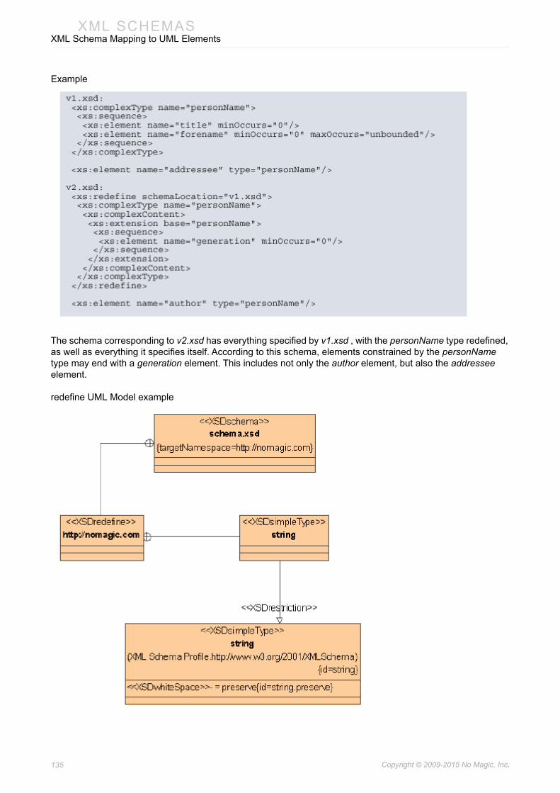
135 Copyright © 2009-2015 No Magic, Inc..
XML SCHEMASXML Schema Mapping to UML Elements
Example
The schema corresponding to v2.xsd has everything specified by v1.xsd , with the personName type redefined, as well as everything it specifies itself. According to this schema, elements constrained by the personName type may end with a generation element. This includes not only the author element, but also the addressee element.
redefine UML Model example

136 Copyright © 2009-2015 No Magic, Inc..
XML SCHEMASXML Schema Mapping to UML Elements
import
Maps to UML Permission with stereotype XSDimport. Permission client must be schema class stereotypes «XSDschema» Component, supplier namespace Package XSDnamespace.
• namespace maps to supplier name.
• annotation maps to UML Attribute documentation.
• schemaLocation maps to TaggedValue.
Example
The same namespace may be used both for real work, and in the course of defining schema components in terms of foreign components:

137 Copyright © 2009-2015 No Magic, Inc..
XML SCHEMASXML Schema Mapping to UML Elements
The treatment of references as ·QNames· implies that since (with the exception of the schema for schemas) the target namespace and the XML Schema namespace differ, without massive redeclaration of the default namespace either internal references to the names being defined in a schema document or the schema declaration and definition elements themselves must be explicitly qualified. This example takes the first option -- most other examples in this specification have taken the second.
import UML Model example

138 Copyright © 2009-2015 No Magic, Inc..
XML SCHEMASXML Schema Mapping to UML Elements
include
Maps to UML Component with stereotype XSDinclude. Component must be added into xsd file component.
• annotation maps to UML Component documentation
• schemaLocation maps to UML Component name.
include UML Model example
XML schema namespaces
Maps to UML Package with stereotype XSDnamespace. In order to define “xmlns” attribute in the schema file, Permission between XSDnamespace package and XSDschema class must be added into the model.
• The Permission name maps to namespace shortcut.
Example:
The XML representation of the skeleton of a schema.
In order to generate such namespaces:
• UML model must have Package with name “http://www.w3.org/2001/XMLSchema”
• UML model must have Package with name “http://www.example.com/example”

139 Copyright © 2009-2015 No Magic, Inc..
XML SCHEMASXML Schema Mapping to UML Elements
• Permission with name “xs” must be added into model between XMLSchema Class and Package “http://www.w3.org/2001/XMLSchema”.
• Permission without name must be added into model between XMLSchema Class and Package “http://www.w3.org/2001/XMLSchema”.
XML schema namespaces UML Model example
For an example, see “schema UML Model example” on page 133.