calculation and optimization of the aerodynamic drag...
TRANSCRIPT
Journal of Engineering Science and Technology EURECA 2013 Special Issue August (2014) 1 - 15 © School of Engineering, Taylor’s University
1
CALCULATION AND OPTIMIZATION OF THE AERODYNAMIC DRAG OF AN OPEN-WHEEL RACE CAR
ABDULKAREEM SH. MAHDI AL-OBAIDI*, LEE CHUNG SUN
School of Engineering, Taylor’s University College, No. 1 Jalan SS 15/8
47500 Subang Jaya, Selangor DE, Malaysia
*Corresponding Author: [email protected]
Abstract
Aerodynamic drag reduction is one of the important factors to make a race car
achieve a faster lap time. Additional drag is produced due to the air channel for
radiator cooling of the student designed open-wheel race car. This paper presents the aerodynamic drag optimization of the race car through studying the effect of
the angle of the radiator air channel numerically using ANSYS Fluent and
experimentally using wind tunnel. A reduction of 12.7% in drag coefficient
compared to the current setup is achieved by tilting the angle of cooling channel
to 72.5 degree. Numerical results and experimental results show good agreement,
a maximum deviation of 7.7% between numerical and experimental drag
coefficient for case of the race car with driver included.
Keywords: Aerodynamic drag, Drag reduction, Drag optimization, ANSYS Fluent,
Automobile drag, CFD.
1. Introduction
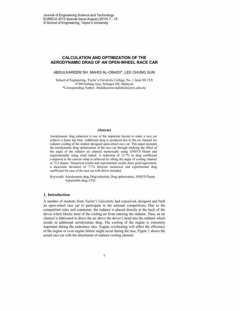
A number of students from Taylor’s University had conceived, designed and built
an open-wheel race car to participate in the national competitions. Due to the
competition rules and constrains, the radiator is placed directly at the back of the
driver which blocks most of the cooling air from entering the radiator. Thus, an air
channel is fabricated to direct the air above the driver’s head into the radiator which
results in additional aerodynamic drag. The cooling of the engine is extremely
important during the endurance race. Engine overheating will affect the efficiency
of the engine or even engine failure might occur during the race. Figure 1 shows the
actual race car with the attachment of radiator cooling channel.
2 A. S. M. Al-Obaidi and C. S. Lee
Journal of Engineering Science and Technology Special Issue 8/2014
Nomenclatures
A Frontal area, m2
CD Total drag coefficient
CDf Skin-friction drag coefficient
CDp Pressure drag coefficient
Dp Pressure drag force, N
P Pressure, Pa
Rl Reynolds number based on reference length
Greek Symbols
θ Angle between relative velocity to the normal pressure force, rad
Fig. 1. The Open-wheel Race Car “Imperica”
with the Cooling Channel Attached.
Vortex generators are normally used on aircraft to delay the flow separation
and are beginning to see applicable to sedan car providing the same function.
Although vortex generators create drag themselves, they also reduce drag by
delaying the flow separation at the downstream. It had been proven by Mitsubishi
Motors Research & Development department that the vortex generators designed
and properly positioned on the roof top of their production car, the Mitsubishi
Lancer Evolution can reduce a drag coefficient of 0.006 [1]. Furthermore, it is
also proven numerically that rear-spoiler on a Camry model is able to reduce the
drag by 1.7% [2].
A wind friction drag reduction system has been suggested by Krishna Mohan
Raju [3]. The drag reduction device is placed at the rear of the vehicle with
collapsible rear attachment to reduce the aerodynamic during high speeds without
increasing the engine capacity. The research showed that the hydraulic controlled
wind friction reduction device increase the velocity by 1.3 times compare to the
conventional configuration [3].
The objective of this paper is to study and compare the effect of the angle of
the radiator cooling channel on the overall drag coefficient of the race car.
Furthermore, conduct computational studies using Computational Fluids
Dynamic (CFD) and experimental wind tunnel studies. Then compare and
analyse the trend of the results from the numerical method and experimental
method. Lastly, an optimum solution for drag reduction of the race car from the
Radiator Cooling Channel
Calculation and Optimization of the Aerodynamic Drag of an Open-Wheel Race Car 3
Journal of Engineering Science and Technology Special Issue 8/2014
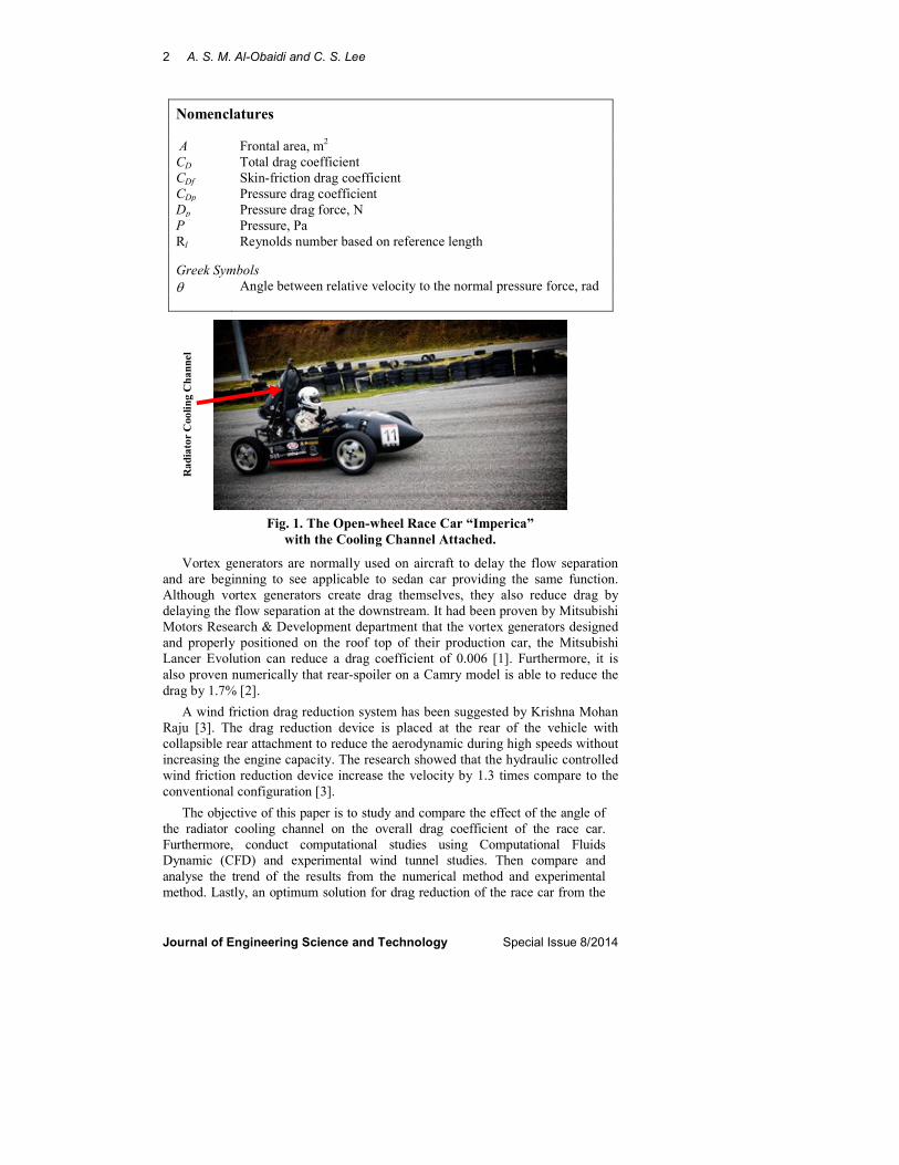
study of the effect on the angle of the radiator cooling channel on aerodynamic
drag is suggested. Figure 2 shows the parametric study conducted in this paper.
Fig. 2. The Parametric Study on the
Angle of the Radiator Cooling Channel.
2. Numerical Approach using Computational Fluid Dynamic (CFD)
ANSYS Fluent 14 software was used to simulate the aerodynamics of the
automobile to obtain the drag coefficient numerically. A simplified vehicle
shape called Ahmed Body was used for verification and validation of the
software [4]. It is also used to determine the proper meshing, turbulence model
and CFD solver input settings for the external flow simulation for the race car
model. Table 1 shows three different simulations on Ahmed Body using
different turbulence models; Realizable k-ε solves two transport equations to
obtain turbulent kinetic energy, k and dissipation rate, ε. The Reynolds Stress
Model (RSM) solves 6 components of Reynolds stresses and dissipation rate, ε
and Large Eddy Simulation (LES) solves the large eddies and models the
smaller eddies [5]. The LES Smagorinsky-Lilly model was also used for the
Ahmed Body verification simulation. The results don’t differ much from
experimental value [4, 6, 7]. Hence, using less computational time to obtain
similar results is highly recommended.
The results from Table 1 shows that the numerical results is within acceptable
range hence the similar meshing and solver input methods were used for the
external flow race car simulations.
Flow
direction
Flow
direction
Flow
direction
Flow
direction
Flow
direction
Flow
direction
4 A. S. M. Al-Obaidi and C. S. Lee
Journal of Engineering Science and Technology Special Issue 8/2014
Table 1. Comparison of CFD results of Ahmed Body.
Realizable k-ε RSM LES
Drag coefficient (CD) 0.316 0.316 0.284
Experimental Drag Coefficient 0.299 0.299 0.299
CD accuracy (%) 5.3 5.3 5.2
Computational Time (hours) 0.5 3 8
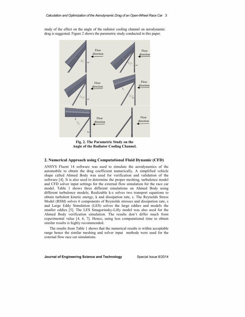
2.1. Geometry and meshing
A full-scale simplified drawing of Taylor’s University Race Car named Imperica in
produced using Solidworks 2011. A computational domain similar to a wind tunnel
test section is created around the car. A domain of 3 car lengths upstream and 5 car
lengths downstream is created to accommodate for the flow development at the
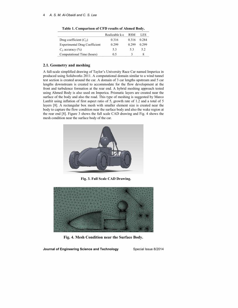
front and turbulence formation at the rear end. A hybrid meshing approach tested
using Ahmed Body is also used on Imperica. Prismatic layers are created near the
surface of the body and also the road. This type of meshing is suggested by Marco
Lanfrit using inflation of first aspect ratio of 5, growth rate of 1.2 and a total of 5
layers [8]. A rectangular box mesh with smaller element size is created near the
body to capture the flow condition near the surface body and also the wake region at
the rear end [8]. Figure 3 shows the full scale CAD drawing and Fig. 4 shows the
mesh condition near the surface body of the car.
Fig. 3. Full Scale CAD Drawing.
Fig. 4. Mesh Condition near the Surface Body.
Calculation and Optimization of the Aerodynamic Drag of an Open-Wheel Race Car 5
Journal of Engineering Science and Technology Special Issue 8/2014
2.2 Turbulence model
Realizable k-ε with non-equilibrium wall function is selected based on the results
obtained from the simulation of Ahmed Body. This is to reduce the time
consumption for simulations and also to help the convergence of the simulation.
The selected turbulence model is enough to give an understanding of the overall
external flow conditions and drag coefficient relationship [8].
Pressure based coupled algorithm is selected for the solver. Pressure based
coupled algorithm solve both continuity and momentum equation simultaneously
and this could help the overall convergence of the simulations but more
computational memory is needed [9].
3. Wind Tunnel: Validation and Verification
Three different size of spheres of diameter 3 cm, 6 cm and 9 cm were
manufactured using the Rapid Prototype Machine (RPM). The purpose of these
three spheres are to validate the results obtained using the force transducer in the
wind tunnel to ensure validity and accuracy of the data obtained. Drag coefficient
for sphere at different Reynolds number are well defined in the literature.
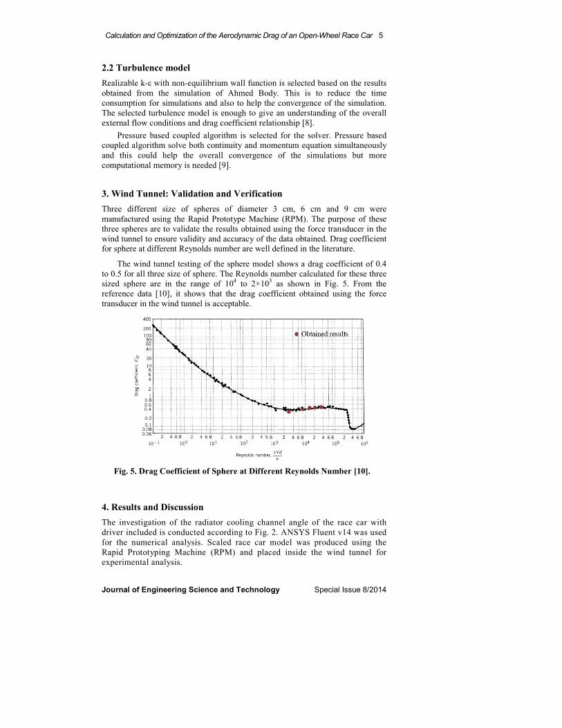
The wind tunnel testing of the sphere model shows a drag coefficient of 0.4
to 0.5 for all three size of sphere. The Reynolds number calculated for these three
sized sphere are in the range of 104 to 2×10
5 as shown in Fig. 5. From the
reference data [10], it shows that the drag coefficient obtained using the force
transducer in the wind tunnel is acceptable.
Fig. 5. Drag Coefficient of Sphere at Different Reynolds Number [10].
4. Results and Discussion
The investigation of the radiator cooling channel angle of the race car with
driver included is conducted according to Fig. 2. ANSYS Fluent v14 was used
for the numerical analysis. Scaled race car model was produced using the
Rapid Prototyping Machine (RPM) and placed inside the wind tunnel for
experimental analysis.
6 A. S. M. Al-Obaidi and C. S. Lee
Journal of Engineering Science and Technology Special Issue 8/2014
4.1. Computational results
Current basic setup total drag coefficient
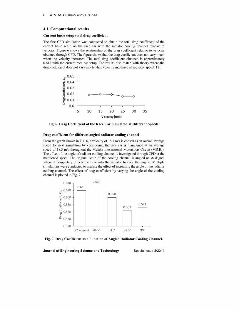
The first CFD simulation was conducted to obtain the total drag coefficient of the
current basic setup on the race car with the radiator cooling channel relative to
velocity. Figure 6 shows the relationship of the drag coefficient relative to velocity
obtained through CFD. The figure shows that the drag coefficient does not vary much
when the velocity increases. The total drag coefficient obtained is approximately
0.618 with the current race car setup. The results also match with theory where the
drag coefficient does not vary much when velocity increased at subsonic speed [11].
Fig. 6. Drag Coefficient of the Race Car Simulated at Different Speeds.
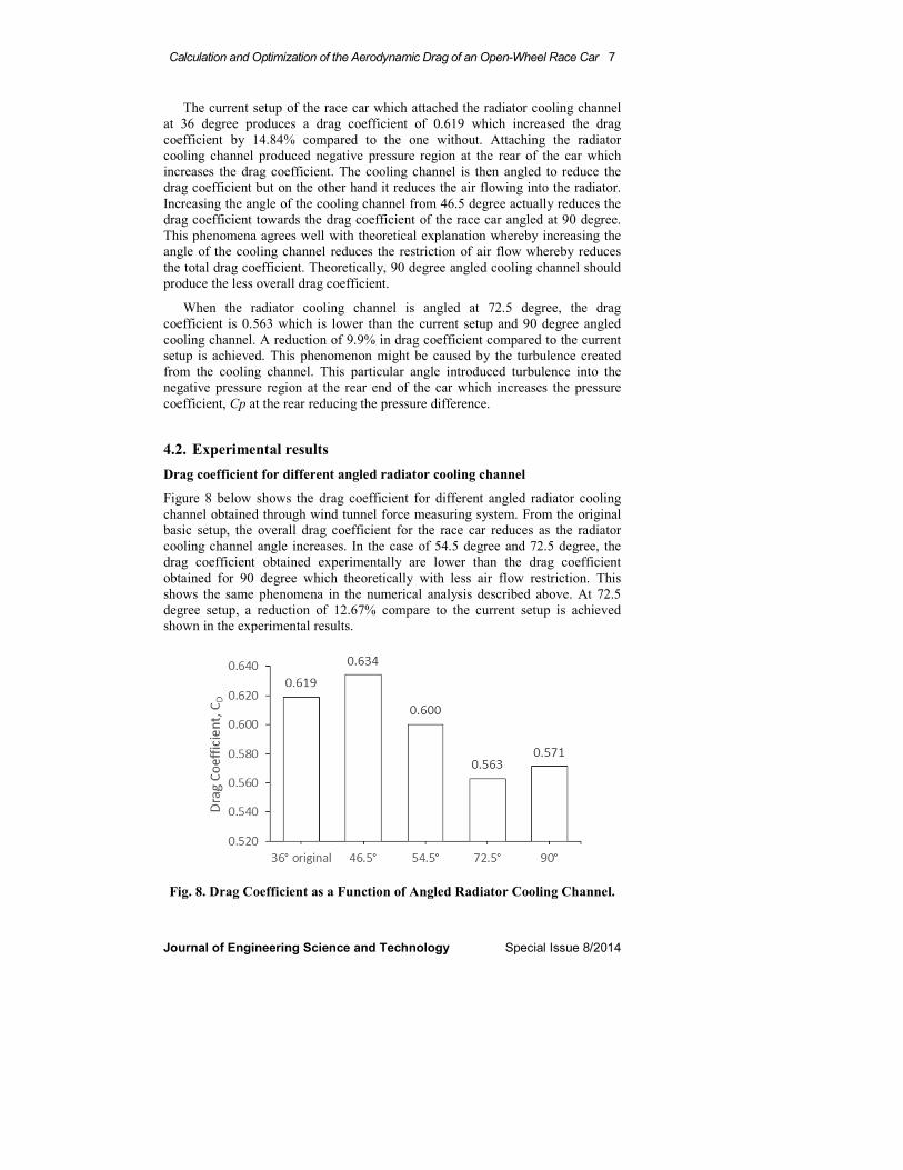
Drag coefficient for different angled radiator cooling channel
From the graph shown in Fig. 6, a velocity of 18.3 m/s is chosen as an overall average
speed for next simulation by considering the race car is maintained at an average
speed of 18.3 m/s throughout the Melaka International Motorsport Circuit (MIMC).
The effect of the angle of radiator cooling channel is investigated through CFD at the
mentioned speed. The original setup of the cooling channel is angled at 36 degree
where it completely directs the flow into the radiator to cool the engine. Multiple
simulations were conducted to analyse the effect of increasing the angle of the radiator
cooling channel. The effect of drag coefficient by varying the angle of the cooling
channel is plotted in Fig. 7.
Fig. 7. Drag Coefficient as a Function of Angled Radiator Cooling Channel.
Calculation and Optimization of the Aerodynamic Drag of an Open-Wheel Race Car 7
Journal of Engineering Science and Technology Special Issue 8/2014
The current setup of the race car which attached the radiator cooling channel
at 36 degree produces a drag coefficient of 0.619 which increased the drag
coefficient by 14.84% compared to the one without. Attaching the radiator
cooling channel produced negative pressure region at the rear of the car which
increases the drag coefficient. The cooling channel is then angled to reduce the
drag coefficient but on the other hand it reduces the air flowing into the radiator.
Increasing the angle of the cooling channel from 46.5 degree actually reduces the
drag coefficient towards the drag coefficient of the race car angled at 90 degree.
This phenomena agrees well with theoretical explanation whereby increasing the
angle of the cooling channel reduces the restriction of air flow whereby reduces
the total drag coefficient. Theoretically, 90 degree angled cooling channel should
produce the less overall drag coefficient.
When the radiator cooling channel is angled at 72.5 degree, the drag
coefficient is 0.563 which is lower than the current setup and 90 degree angled
cooling channel. A reduction of 9.9% in drag coefficient compared to the current
setup is achieved. This phenomenon might be caused by the turbulence created
from the cooling channel. This particular angle introduced turbulence into the
negative pressure region at the rear end of the car which increases the pressure
coefficient, Cp at the rear reducing the pressure difference.
4.2. Experimental results
Drag coefficient for different angled radiator cooling channel
Figure 8 below shows the drag coefficient for different angled radiator cooling
channel obtained through wind tunnel force measuring system. From the original
basic setup, the overall drag coefficient for the race car reduces as the radiator
cooling channel angle increases. In the case of 54.5 degree and 72.5 degree, the
drag coefficient obtained experimentally are lower than the drag coefficient
obtained for 90 degree which theoretically with less air flow restriction. This
shows the same phenomena in the numerical analysis described above. At 72.5
degree setup, a reduction of 12.67% compare to the current setup is achieved
shown in the experimental results.
Fig. 8. Drag Coefficient as a Function of Angled Radiator Cooling Channel.
8 A. S. M. Al-Obaidi and C. S. Lee
Journal of Engineering Science and Technology Special Issue 8/2014
4.3. Comparison
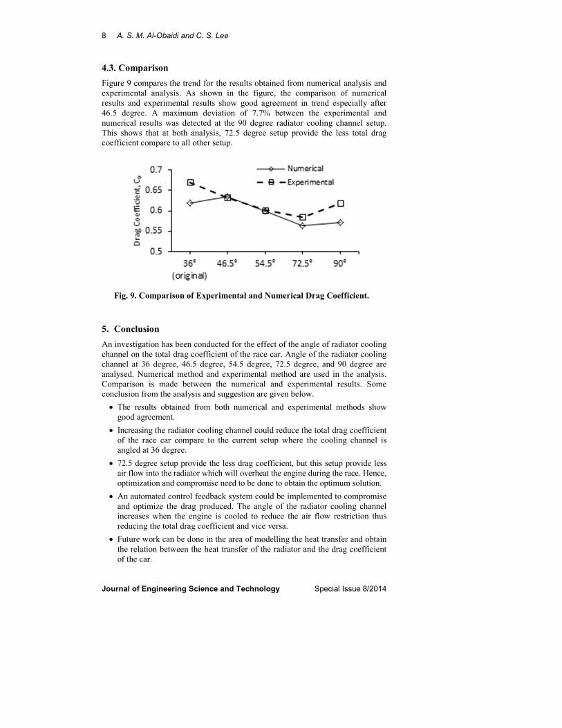
Figure 9 compares the trend for the results obtained from numerical analysis and
experimental analysis. As shown in the figure, the comparison of numerical
results and experimental results show good agreement in trend especially after
46.5 degree. A maximum deviation of 7.7% between the experimental and
numerical results was detected at the 90 degree radiator cooling channel setup.
This shows that at both analysis, 72.5 degree setup provide the less total drag
coefficient compare to all other setup.
Fig. 9. Comparison of Experimental and Numerical Drag Coefficient.
5. Conclusion
An investigation has been conducted for the effect of the angle of radiator cooling
channel on the total drag coefficient of the race car. Angle of the radiator cooling
channel at 36 degree, 46.5 degree, 54.5 degree, 72.5 degree, and 90 degree are
analysed. Numerical method and experimental method are used in the analysis.
Comparison is made between the numerical and experimental results. Some
conclusion from the analysis and suggestion are given below.
• The results obtained from both numerical and experimental methods show
good agreement.
• Increasing the radiator cooling channel could reduce the total drag coefficient
of the race car compare to the current setup where the cooling channel is
angled at 36 degree.
• 72.5 degree setup provide the less drag coefficient, but this setup provide less
air flow into the radiator which will overheat the engine during the race. Hence,
optimization and compromise need to be done to obtain the optimum solution.
• An automated control feedback system could be implemented to compromise
and optimize the drag produced. The angle of the radiator cooling channel
increases when the engine is cooled to reduce the air flow restriction thus
reducing the total drag coefficient and vice versa.
• Future work can be done in the area of modelling the heat transfer and obtain
the relation between the heat transfer of the radiator and the drag coefficient
of the car.
Calculation and Optimization of the Aerodynamic Drag of an Open-Wheel Race Car 9
Journal of Engineering Science and Technology Special Issue 8/2014
References
1. Koike, M.; Nagayoshi, T.; and Hamamoto, N. (2004). Research on
aerodynamic drag reduction by vortex generators. Mitsubishi Technical
Review, 16, 11-16.
2. Hu, X.-X.; and Wong, E.T.T. (2011). A numerical study on rear-spoiler of
passenger vehicle. World Academy of Science, Engineering and Technology,
5(9), 575-582.
3. Raju, K.M.; and Reddy, G.J. (2012). A conceptual design of wind friction
reduction attachments to the rear portion of a car for better fuel economy at
high speeds. International Journal of Engineering Science and Technology,
4(5), 2366-2372.
4. Ram, G.; and Faltin, G. (1984). Some salient features of the time-average
ground vehicle wake in Detroit. Society of Automotive Engineers.
5. Versteeg, H.K.; and Malalasekera, W. (1995). An introdution to
Computational Fluid Dynamics. Harlow: Pearson Education Limited.
6. Gabriel. A.; Drage, P.; Lindbichler. G.; Hormann. T.; Brenn, G.; and Meile,
W. (2008). Efficient use of computational fluid dynamics for the
aerodynamic developmet process in the automotive industry. 26th AIAA
Applied Aerodynamics Conference. AIAA 2008- 6735.
7. Lienhart, H.; and Becker, S. (2003). Flow and turbulence structure in the
wake of a simplified car model in Michigan, USA. SAE 2003 World
Congress, SAE Paper 2003-01-0656.
8. Marco, L. (2005). Best practice guidelines for handling Automotive External
Aerodynamics with Fluent. Birkenweg: Fluent Deutschland GmbH.
9. Keating, M. (2011). Accelerating CFD Solutions. ANSYS, Inc.
10. Schlichting, H. (1979). Boundary Layer. (7th
Ed.), McGraw-Hill Book
Company, New York.
11. Hoerner, S.F. (1965). Fluid-Dynamic Drag. Hoerner Fluid Dynamics, Brick
Town N.J.
10 A. S. M. Al-Obaidi and C. S. Lee
Journal of Engineering Science and Technology Special Issue 8/2014
Appendix A
Residual plots and Convergence graphs in ANSYS Fluent
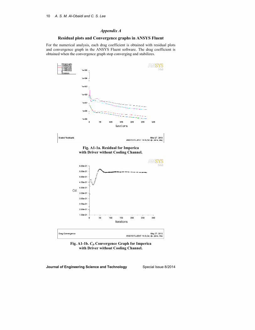
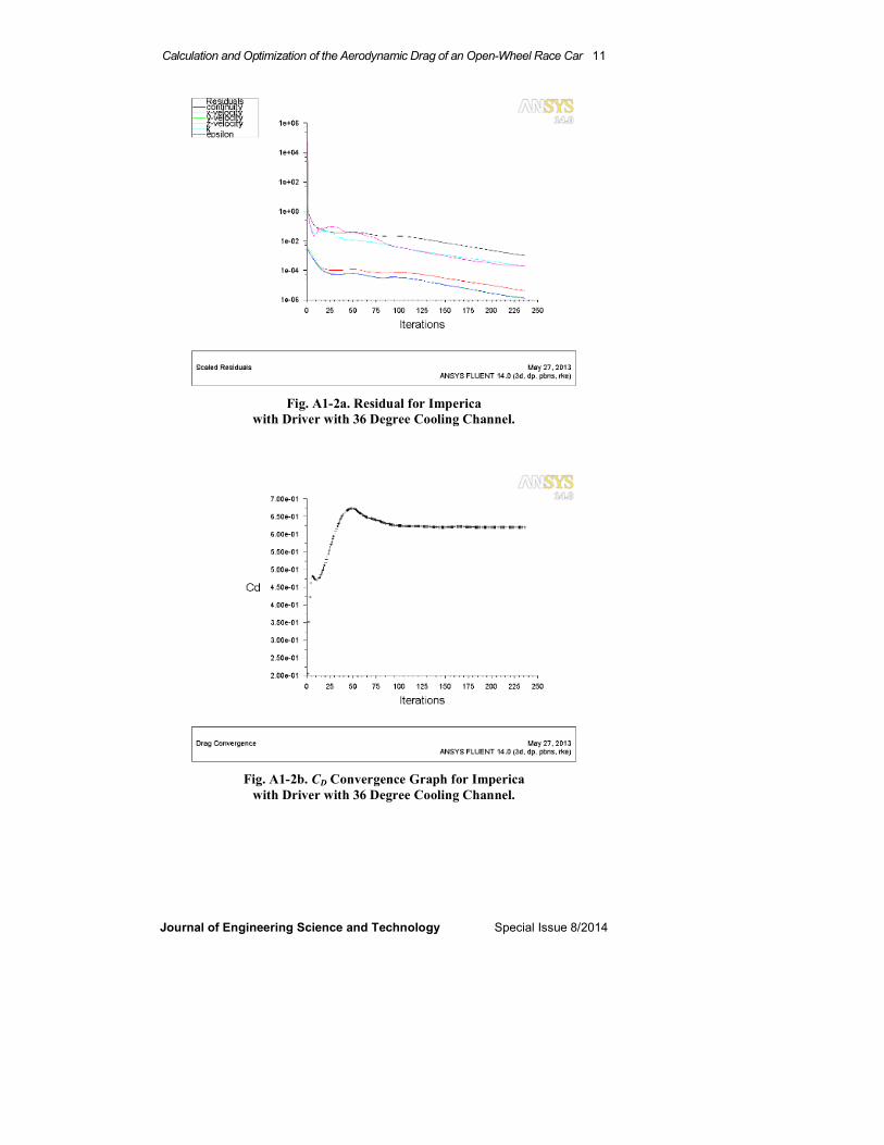
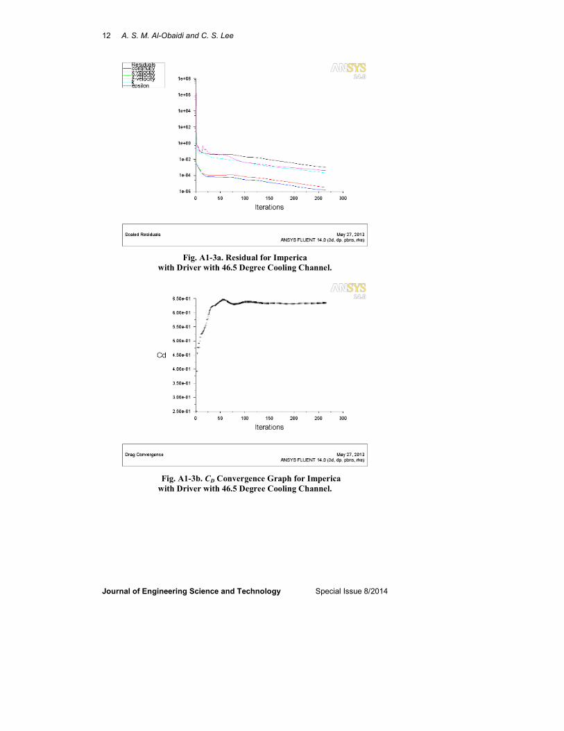
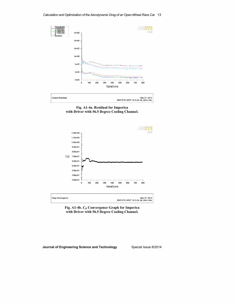
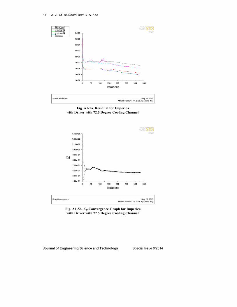
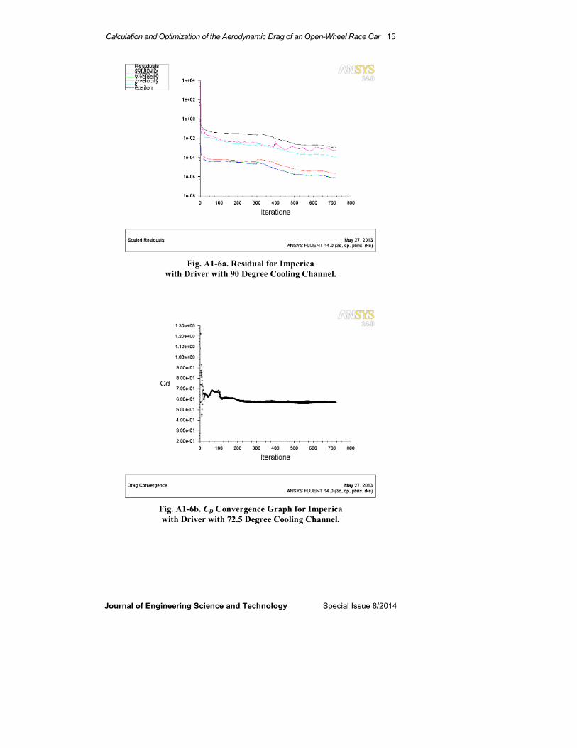
For the numerical analysis, each drag coefficient is obtained with residual plots
and convergence graph in the ANSYS Fluent software. The drag coefficient is
obtained when the convergence graph stop converging and stabilizes.
Fig. A1-1a. Residual for Imperica
with Driver without Cooling Channel.
Fig. A1-1b. CD Convergence Graph for Imperica
with Driver without Cooling Channel.
Calculation and Optimization of the Aerodynamic Drag of an Open-Wheel Race Car 11
Journal of Engineering Science and Technology Special Issue 8/2014
Fig. A1-2a. Residual for Imperica
with Driver with 36 Degree Cooling Channel.
Fig. A1-2b. CD Convergence Graph for Imperica
with Driver with 36 Degree Cooling Channel.
12 A. S. M. Al-Obaidi and C. S. Lee
Journal of Engineering Science and Technology Special Issue 8/2014
Fig. A1-3a. Residual for Imperica
with Driver with 46.5 Degree Cooling Channel.
Fig. A1-3b. CD Convergence Graph for Imperica
with Driver with 46.5 Degree Cooling Channel.
Calculation and Optimization of the Aerodynamic Drag of an Open-Wheel Race Car 13
Journal of Engineering Science and Technology Special Issue 8/2014
Fig. A1-4a. Residual for Imperica
with Driver with 56.5 Degree Cooling Channel.
Fig. A1-4b. CD Convergence Graph for Imperica
with Driver with 56.5 Degree Cooling Channel.
14 A. S. M. Al-Obaidi and C. S. Lee
Journal of Engineering Science and Technology Special Issue 8/2014
Fig. A1-5a. Residual for Imperica
with Driver with 72.5 Degree Cooling Channel.
Fig. A1-5b. CD Convergence Graph for Imperica
with Driver with 72.5 Degree Cooling Channel.
Calculation and Optimization of the Aerodynamic Drag of an Open-Wheel Race Car 15
Journal of Engineering Science and Technology Special Issue 8/2014
Fig. A1-6a. Residual for Imperica
with Driver with 90 Degree Cooling Channel.
Fig. A1-6b. CD Convergence Graph for Imperica
with Driver with 72.5 Degree Cooling Channel.