cac odu-north im en db68-05462a-08 170309 · 3 english safety precautions warning state of...
TRANSCRIPT

AC024JXADCHAC030JXADCHAC036JXADCHAC042JXADCHAC048JXADCHAC030JXSCCHAC036JXSCCHAC054KXADCH
Air Conditionerinstallation manual
imagine the possibilitiesThank you for purchasing this Samsung product.

2
ContentsPREPARATIONSafety precautions . . . . . . . . . . . . . . . . . . . . . . . . . . . . . . . . . . . . . . . . . . . . . . . . . . . . . . . . . . . . . . . . . . . . . . . . . . . . . . . . . . . . . . . . . . . . . . . . . . . . . . . 3Preparation for outdoor unit installation . . . . . . . . . . . . . . . . . . . . . . . . . . . . . . . . . . . . . . . . . . . . . . . . . . . . . . . . . . . . . . . . . . . . . . . . . . . . . . . . . 5Deciding on where to install the outdoor unit . . . . . . . . . . . . . . . . . . . . . . . . . . . . . . . . . . . . . . . . . . . . . . . . . . . . . . . . . . . . . . . . . . . . . . . . . . . . 7Outdoor unit installation . . . . . . . . . . . . . . . . . . . . . . . . . . . . . . . . . . . . . . . . . . . . . . . . . . . . . . . . . . . . . . . . . . . . . . . . . . . . . . . . . . . . . . . . . . . . . . . . 13
INSTALLATIONConnecting the cable . . . . . . . . . . . . . . . . . . . . . . . . . . . . . . . . . . . . . . . . . . . . . . . . . . . . . . . . . . . . . . . . . . . . . . . . . . . . . . . . . . . . . . . . . . . . . . . . . . . 15Connecting the refrigerant pipe . . . . . . . . . . . . . . . . . . . . . . . . . . . . . . . . . . . . . . . . . . . . . . . . . . . . . . . . . . . . . . . . . . . . . . . . . . . . . . . . . . . . . . . . . 23Adding refrigerant (R-410A) . . . . . . . . . . . . . . . . . . . . . . . . . . . . . . . . . . . . . . . . . . . . . . . . . . . . . . . . . . . . . . . . . . . . . . . . . . . . . . . . . . . . . . . . . . . . . 24Connecting to the system and removing air in the circuit . . . . . . . . . . . . . . . . . . . . . . . . . . . . . . . . . . . . . . . . . . . . . . . . . . . . . . . . . . . . . . . . 25Connecting the drain hose to the outdoor unit . . . . . . . . . . . . . . . . . . . . . . . . . . . . . . . . . . . . . . . . . . . . . . . . . . . . . . . . . . . . . . . . . . . . . . . . . . 27Cutting/Flaring the pipes . . . . . . . . . . . . . . . . . . . . . . . . . . . . . . . . . . . . . . . . . . . . . . . . . . . . . . . . . . . . . . . . . . . . . . . . . . . . . . . . . . . . . . . . . . . . . . . 28Performing leak tests . . . . . . . . . . . . . . . . . . . . . . . . . . . . . . . . . . . . . . . . . . . . . . . . . . . . . . . . . . . . . . . . . . . . . . . . . . . . . . . . . . . . . . . . . . . . . . . . . . . 29Refrigerant pipe work . . . . . . . . . . . . . . . . . . . . . . . . . . . . . . . . . . . . . . . . . . . . . . . . . . . . . . . . . . . . . . . . . . . . . . . . . . . . . . . . . . . . . . . . . . . . . . . . . . . 29Using stop valve . . . . . . . . . . . . . . . . . . . . . . . . . . . . . . . . . . . . . . . . . . . . . . . . . . . . . . . . . . . . . . . . . . . . . . . . . . . . . . . . . . . . . . . . . . . . . . . . . . . . . . . . 30Interface module Installation (Optional) . . . . . . . . . . . . . . . . . . . . . . . . . . . . . . . . . . . . . . . . . . . . . . . . . . . . . . . . . . . . . . . . . . . . . . . . . . . . . . . . . 31Pump down Procedure . . . . . . . . . . . . . . . . . . . . . . . . . . . . . . . . . . . . . . . . . . . . . . . . . . . . . . . . . . . . . . . . . . . . . . . . . . . . . . . . . . . . . . . . . . . . . . . . . 32Checking correct grounding . . . . . . . . . . . . . . . . . . . . . . . . . . . . . . . . . . . . . . . . . . . . . . . . . . . . . . . . . . . . . . . . . . . . . . . . . . . . . . . . . . . . . . . . . . . . 33Testing operations . . . . . . . . . . . . . . . . . . . . . . . . . . . . . . . . . . . . . . . . . . . . . . . . . . . . . . . . . . . . . . . . . . . . . . . . . . . . . . . . . . . . . . . . . . . . . . . . . . . . . . 34Installing the wind baffle . . . . . . . . . . . . . . . . . . . . . . . . . . . . . . . . . . . . . . . . . . . . . . . . . . . . . . . . . . . . . . . . . . . . . . . . . . . . . . . . . . . . . . . . . . . . . . . 37Troubleshooting . . . . . . . . . . . . . . . . . . . . . . . . . . . . . . . . . . . . . . . . . . . . . . . . . . . . . . . . . . . . . . . . . . . . . . . . . . . . . . . . . . . . . . . . . . . . . . . . . . . . . . . . 38
OTHERS
IMPORTANT – This product has been designed and manufactured to meet ENERGY STAR criteria for energy efficiency when matched with appropriate coil components.However, proper refrigerant charge and proper air flow are critical to achieve rated capacity and efficiency. Installation of this product should follow the manufacturer’s refrigerant charging and air flow instructions. Failure to confirm proper charge and airflow may reduce energy efficiency and shorten equipment life.

3
ENGLISH
Safety precautions
WARNING
State of California Proposition 65 Warning (US only)This product contains chemicals known to the State of California to cause cancer and birth defects or other reproductive harm.
Carefully follow the precautions listed below because they are essential to guarantee the safety of the equipment.
WARNING
• Always disconnect the air conditioner from the power supply before servicing it or accessing its internal components.
• Verify that installation and testing operations are performed by qualified personnel. • Verify that the air conditioner is not installed in an easily accessible area.
General information
Carefully read the content of this manual before installing the air conditioner and store the manual in a safe place in order to be able to use it as reference after installation. For maximum safety, installers should always carefully read the following warnings.Store the operation and installation manual in a safe location and remember to hand it over to the new owner if the air conditioner is sold or transferred.This manual explains how to install an indoor unit with a split system with two SAMSUNG units. The use of other types of units with different control systems may damage the units and invalidate the warranty. The manufacturer shall not be responsible for damages arising from the use of non compliant units.The manufacturer shall not be responsible for damage originating from unauthorized changes or the improper connection of electric and requirements set forth in the “Operating limits” table, included in the manual, shall immediately invalidate the warranty.The air conditioner should be used only for the applications for which it has been designed: the indoor unit is not suitable to be installed in areas used for laundry.Do not use the units if damaged. If problems occur, switch the unit off and disconnect it from the power supply.In order to prevent electric shocks, fires or injuries, always stop the unit, disable the protection switch and contact SAMSUNG’s technical support if the unit produces smoke, if the power cable is hot or damaged or if the unit is very noisy.Always remember to inspect the unit, electric connections, refrigerant tubes and protections regularly. These operations should be performed by qualified personnel only.The unit contains moving parts, which should always be kept out of the reach of children.Do not attempt to repair, move, alter or reinstall the unit. If performed by unauthorized personnel, these operations may cause electric shocks or fires.Do not disassemble and alter the heater at your own discretion. * (Applicable model : AC030JXSCCH, AC036JXSCCH)Do not place containers with liquids or other objects on the unit.All the materials used for the manufacture and packaging of the air conditioner are recyclable.The packing material and exhaust batteries of the remote controller(optional) must be disposed of in accordance with current laws.The air conditioner contains a refrigerant that has to be disposed of as special waste. At the end of its life cycle, the air conditioner must be disposed of in authorized centers or returned to the retailer so that it can be disposed of correctly and safely.This appliance is not intended for use by persons (including children) with reduced physical, sensory or mental capabilities, or lack of experience and knowledge, unless they have been given supervision or instruction concerning use of the appliance by a person responsible for their safety. Children should be supervised to ensure that they do not play with the appliance.
4
Installing the unit
IMPORTANT: When installing the unit, always remember to connect first the refrigerant tubes, then the electrical lines. Always disassemble the electric lines before the refrigerant tubes.
Upon receipt, inspect the product to verify that it has not been damaged during transport. If the product appears damaged, DO NOT INSTALL it and immediately report the damage to the carrier or retailer (if the installer or the authorized technician has collected the material from the retailer.)After completing the installation, always carry out a functional test and provide the instructions on how to operate the air conditioner to the user.Do not use the air conditioner in environments with hazardous substances or close to equipment that release free flames to avoid the occurrence of fires, explosions or injuries.Our units should be installed in compliance with the spaces shown in the installation manual, to ensure accessibility from both sides and allow repairs or maintenance operations to be carried out. The unit’s components should be accessible and easy to disassemble without endangering people and objects.For this reason, when provisions of the installation manual are not complied with, the cost required to access and repair the units (in SAFETY CONDITIONS, as set out in prevailing regulations) with harnesses, ladders, scaffolding or any other elevation system will NOT be considered part of the warranty and will be charged to the end customer.If you operate the cooling operation of air conditioner in the condition where ambient temperature is lower than 23 °F DB(Dry bulb), a wind baffle should be installed to protect the compressor of the outdoor unit.
Power supply line, fuse or circuit breaker
Always make sure that the power supply is compliant with current safety standards. Always install the air conditioner in compliance with current local safety standards.Always verify that a suitable grounding connection is available.Verify that the voltage and frequency of the power supply comply with the specifications and that the installed power is sufficient to ensure the operation of any other domestic appliance connected to the same electric lines.Always verify that the cut-off and protection switches are suitably dimensioned.Verify that the air conditioner is connected to the power supply in accordance with the instructions provided in the wiring diagram included in the manual.Always verify that electric connections (cable entry, section of leads, protections…) are compliant with the electric specifications and with the instructions provided in the wiring scheme. Always verify that all connections comply with the standards applicable to the installation of air conditioners.Devices disconnected from the power supply should be completely disconnected in the condition of overvoltage category.Be sure not to perform power cable modification, extension wiring, and multiple wire connection. - It may cause electric shock or fire due to poor connection, poor insulation, or current limit override. - When extension wiring is required due to power line damage, refer to “How to connect your extended power cables” in
the installation manual.
Safety precautions

5
ENGLISH
Preparation for outdoor unit installationThe air conditioner uses R-410A refrigerant.
Outdoor unit dimensionA Type AC024JXADCH / AC030JXADCH
(Unit : inch)24.4
37.0
13.0
38.3
39.3
26.6
20.8
21.1
14.2
15.1
B Type AC036JXADCH / AC042JXADCH / AC048JXADCH
24.4
37.0
13.0
46.7
47.6
34.8
22.0
22.3
14.2
15.1
C Type AC030JXSCCH / AC036JXSCCH / AC054KXADCH
37.0
54.9
55.9
43.1
22.0
22.3
24.4
13.0
14.2
15.1

6
Preparation for outdoor unit installation
Moving the Outdoor Unit by Wire Rope
Fasten the outdoor unit by two wire ropes (26.3 ft or longer) as shown in the figure. To prevent from damage or scratches, insert a piece of cloth between the outdoor unit and rope, then move the unit.
❋ The appearance of the unit may be different from the picture depending on the model. Plate protection
cloth
Wire rope
When moving an outdoor unit by handMoving the outdoor unit by lifting up and carrying due to the short travel distance. - Two people should carry the outdoor unit. - Be careful not to damage the heat exchanger of the rear side of the outdoor unit during transportation. - Be careful not to get hurt by the sharp surface of the heat exchanger.

7
ENGLISH
Deciding on where to install the outdoor unit
Outdoor UnitThe outdoor unit must not be placed on its side or upside down, as the compressor lubrication oil will run into the cooling circuit and seriously damage the unit.Choose a location that is dry and sunny, but not exposed to direct sunlight or strong winds.Do not block any passageways or thoroughfares.Choose a location where the noise of the air conditioner when running and the discharged air do not disturb any neighbours.Choose a position that enables the pipes and cables to be easily connected to the indoor unit.Install the outdoor unit on a flat, stable surface that can support its weight and does not generate any unnecessary noise and vibration. Position the outdoor unit so that the air flow is directed towards the open area. Maintain sufficient clearance around the outdoor unit, especially from a radio, computer, stereo system, etc.
Fuse
Outdoor Unit
Stereo
5 ft or m
ore
Indoor Unit Control
Air Guide Duct(This product is not provided by Samsung)
3.3
ft or
mor
e
3.3
ft or
mor
e
5 ft
or m
ore
5 ft or m
ore
5 ft or more
Fuse
8 inch
12 inch
If the outdoor unit is installed at a height, ensure that its base is firmly fixed in position. When you install the outdoor unit at wayside, you should install it above 6.6 ft height or make sure that the heat from the outdoor unit shouldn't be in direct contact with passersby.
• You have just purchased a system air conditioner and it has been installed by your installation specialist.• This device must be installed according to the national electrical rules.CAUTION

8
Deciding on where to install the outdoor unitWhen installing the outdoor unit near seashore, make sure it is not directly exposed to sea breeze. If you can not find a adequate place without direct see breeze, protection wall should be constructed.
- Install the outdoor unit in a place (such as near buildings etc.) where it can be protected from sea breeze which can damage the outdoor unit.
Outdoor unit Outdoor unit
Sea breeze Sea breeze
Sea Sea
- If you cannot avoid installing the outdoor unit by the seashore, construct a protection wall around to block the sea breeze.
Protection wall should be constructed with a solid material such as concrete to block the sea breeze and the height and the width of the wall should be 1.5 times larger than the size of the outdoor unit. Also, secure over 27.6 inch between the protection wall and the outdoor unit for exhausted air to ventilate.
Protection wall Outdoor unit
Sea breeze
Sea
- Install the outdoor unit in a place where water can drain smoothly.• If you cannot find a place satisfying above conditions, please contact manufacturer. Make sure to clean the sea water
and the dust on the outdoor unit heat exchanger and spread corrosion inhibitor on heat exchanger. (At least one time per one year.)
• In areas with heavy snow fall, piled snow could block the air intake. To avoid this incident, install a frame that is higher than estimated snow fall. In addition, install a snow-proof hood to avoid snow from piling on the outdoor unit.
CAUTION
Frame
Ground
Estimated snow fall
Snow-proof hood

9
ENGLISH
Space Requirements for Outdoor Unit
When installing 1 outdoor unit
(Unit : inch)
11.8
1 or
mor
e
59.0
6 or
mor
e
❋ When the air outlet is opposite the wall ❋ When the air outlet is towards the wall
11.8
1 or
mor
e
5.91 or more 23.62 or more
59.0
6 or
mor
e
78.74 or more
❋ When 3 sides of the outdoor unit are blocked by a wall ❋ The upper part of the outdoor unit and the air outlet is towards the wall
19.6
9 or
mor
e
11.81 or more11
.81
or m
ore
59.0
6 or
mor
e
❋ The upper part of the outdoor unit and the air outlet is opposite the wall
❋ When front and rear side of the outdoor unit is towards the wall

10
Deciding on where to install the outdoor unitWhen installing 1 outdoor unit (with wind baffle)
Wind baffle is not supplied with the product.
(Unit : inch)
11.8
1 or
mor
e
59.0
6 or
mor
e
❋ When the air outlet is opposite the wall ❋ When the air outlet is towards the wall
11.8
1 or
mor
e
5.91 or more 23.62 or more
59.0
6 or
mor
e
78.74 or more
❋ When 3 sides of the outdoor unit are blocked by a wall ❋ The upper part of the outdoor unit and the air outlet is towards the wall
19.6
9 or
mor
e
11.81 or more
11.8
1 or
mor
e59
.06
or m
ore
❋ The upper part of the outdoor unit and the air outlet is opposite the wall
❋ When front and rear side of the outdoor unit is towards the wall

11
ENGLISH
When installing more than 1 outdoor unit
(Unit : inch)
59.0
6 or
mor
e
❋ When the air outlet is towards the wall
11.8
1 or
m
ore
11.81 or more 23.62 or more 23.62 or more 23.62 or more
❋ When 3 sides of the outdoor unit are blocked by a wall11
.81
or
mor
e59
.06
or m
ore
23.62 or more 23.62 or more
❋ When front and rear side of the outdoor unit is towards a wall
59.06 or more 23.62 or more 118.11 or more 7.87 or more118.11 or more
❋ When 3 sides of the outdoor unit are blocked by a wall
• The units must be installed according to the distances specified above in order to permit accessibility from each side to guarantee correct operation and for future maintenance or repair. The unit’s parts must be safely accessible and completely removable.
CAUTION
When installing more than 1 outdoor unit (with wind baffle)
Wind baffle is not supplied with the product.
(Unit : inch)
59.0
6 or
mor
e
❋ When the air outlet is towards a wall

12
Deciding on where to install the outdoor unit
11.8
1 or
mor
e
11.81 or more 23.62 or more 23.62 or more 23.62 or more
❋ When 3 sides of the outdoor unit are blocked by a wall
11.8
1 or
m
ore
59.0
6 or
mor
e23.62 or more 23.62 or more
❋ When front and rear side of the outdoor unit is towards a wall
59.06 or more 23.62 or more 118.11 or more 7.87 or more118.11 or more
❋ When 3 sides of the outdoor unit are blocked by a wall
• Should adopt bar type louver. Don’t use a type of rain resistance louver.
[Bar type louver] [Rain resistance louver]
• Louver specifications. - Angle criteria : less than 20˚ - Opening ratio criteria : greater than 80%
WARNING
13
ENGLISH
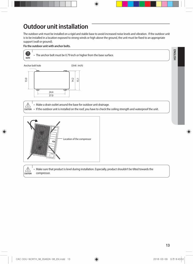
Outdoor unit installationThe outdoor unit must be installed on a rigid and stable base to avoid increased noise levels and vibration. If the outdoor unit is to be installed in a location exposed to strong winds or high above the ground, the unit must be fixed to an appropriate support (wall or ground).Fix the outdoor unit with anchor bolts.
• The anchor bolt must be 0.79 inch or higher from the base surface.NOTE
(Unit : inch)Anchor bolt hole
13.0
14.2
15.1
24.437.0
• Make a drain outlet around the base for outdoor unit drainage.• If the outdoor unit is installed on the roof, you have to check the ceiling strength and waterproof the unit.CAUTION
Location of the compressor
• Make sure that product is level during installation. Especially, product shouldn’t be tilted towards the compressor.CAUTION

14
Outdoor unit installationOutdoor Unit Support
Anchor bolt
0.79
inch
Outdoor Unit
Base Surface
Outdoor Unit Support
Designed to cut off residual vibration from outdoor unit to rack.
OUTDOOR UNIT INSTALLED ON RISERS/STAND OR WALL INSTALLATIONEnsure the wall will be able to support the weight of rack and outdoor unit.Install the rack close to the column as much as possible.Install proper grommet in order to reduce noise and residual vibration transferred by outdoor unit towards wall.
When installing air guide duct• Check and make sure that screws do not damage the copper
pipe.• Secure air guide duct on guard fan.
CAUTION
Soft rubber designed to cut off vibration from rack to wall.
(not supplied with product)

15
ENGLISH
Connecting the cableTwo electronic cables must be connected to the outdoor unit.
The connection cord between indoor unit and outdoor unit.The power cable between outdoor unit and auxiliary circuit breaker. Be sure to run the power supply cable and the communication cable through electrical conduit as seen in the picture.Separately protect the power and communication cable using approved conduit. - Conduit is not supplied with the product.
Make a knockout hole.After making a knockout hole, apply rust resisting paint around the hole.Secure the cable tube to the outdoor knockout using the CD connector and bushing.
• During unit installation make refrigerant connections first then electrical connections. If removing the unit disconnect electrical cables first, then refrigerant connections.
• Connect the air conditioner to grounding system before performing the electrical connection.
• When installing the unit, you shouldn't use inter connection wire.
CAUTION
Conduit
Example of Air Conditioner System
When using ELCB for 1 phase
Indoor Unit
Power cable
Outdoor Unit Communication cable
Grounding
OR
Power cableCommunication cable
❋ If an outdoor unit is installed in a place in danger of an electric leak or submergence, you must install the ELCB.
• AC030JXSCCH, AC036JXSCCH - ELCB must be installed since this product is equipped with a base heater.CAUTION

16
Connecting the cable
Power Cable SpecificationsThe power cable is not supplied with air conditioner. - Select the power supply cable in accordance with relevant local and national regulations. - Wire size must comply with the applicable local and national code. - Specifications for local wiring power cord and branch wiring are in compliance with local cord.
Type
ModelPower source RLA (A)
FLA
MCA MOPOutdoor Unit Indoor Unit
Outdoor Unit Indoor Unit
FAN1 (A) FAN2 (A) FAN1 (A) FAN2 (A)
A
AC024JXADCH/AA
AC024JN4DCH/AA
208~230 V / 60 Hz
9.00
0.48 0.33 12.06 20AC024KN4DCH/AA 0.48 0.33 12.06 20AC024NN4DCH/AA 0.48 0.33 12.06 20AC024JNHDCH/AA 0.48 0.85 12.58 20AC024KNZDCH/AA 0.48 1.85 13.58 20AC024MNHDCH/AA 0.48 1.5 13.5 20AC024MNADCH/AA 0.48 0.7 12.5 20
AC030JXADCH/AA
AC030JN4DCH/AA
15.10
0.48 0.35 19.705 30AC030KN4DCH/AA 0.48 0.35 19.705 30AC030NN4DCH/AA 0.48 0.35 19.705 30AC030JNHDCH/AA 0.48 1.9 1.9 23.155 35AC030KNZDCH/AA 0.48 2.35 21.71 35AC030MNHDCH/AA 0.48 1.5 23 35AC030MNTDCH/AA 0.48 0.9 20.3 30
B
AC036JXADCH/AA
AC036JN4DCH/AA
17.00
0.48 0.48 0.35 22.08 35AC036KN4DCH/AA 0.48 0.48 0.35 22.08 35AC036NN4DCH/AA 0.48 0.48 0.35 22.08 35AC036JNHDCH/AA 0.48 0.48 1.9 1.9 25.53 40AC036KNZDCH/AA 0.48 0.48 4.15 26.36 40AC036MNHDCH/AA 0.48 0.48 2 26.5 40AC036MNTDCH/AA 0.48 0.48 0.9 23.2 35
AC042JXADCH/AA
AC042JN4DCH/AA
17.00
0.48 0.48 0.35 22.08 35AC042KN4DCH/AA 0.48 0.48 0.35 22.08 35AC042NN4DCH/AA 0.48 0.48 0.35 22.08 35AC042JNHDCH/AA 0.48 0.48 1.9 1.9 25.53 40AC042KNZDCH/AA 0.48 0.48 4.15 26.36 40AC042MNHDCH/AA 0.48 0.48 2 26.5 40
AC048JXADCH/AA
AC048JN4DCH/AA
17.00
0.48 0.48 0.35 22.08 35AC048KN4DCH/AA 0.48 0.48 0.35 22.08 35AC048NN4DCH/AA 0.48 0.48 0.35 22.08 35AC048JNHDCH/AA 0.48 0.48 1.9 1.9 25.53 40AC048KNZDCH/AA 0.48 0.48 4.15 26.36 40AC048MNHDCH/AA 0.48 0.48 2 26.5 40
C
AC030JXSCCH/AA
AC030JN4DCH/AA
20.00
0.48 0.48 0.35 26.31 45AC030NN4DCH/AA 0.48 0.48 0.35 26.31 45AC030JNHDCH/AA 0.48 0.48 1.9 1.9 29.76 45AC030KNZDCH/AA 0.48 0.48 2.35 32 45
AC036JXSCCH/AA
AC036JN4DCH/AA
20.00
0.48 0.48 0.35 26.31 45AC036NN4DCH/AA 0.48 0.48 0.35 26.31 45AC036JNHDCH/AA 0.48 0.48 1.9 1.9 29.76 45
AC036KNZDCH/AA 0.48 0.48 4.15 32 45
AC054KXADCH/AA AC054KNZDCH/AA 28.50 0.48 0.48 5.05 41.64 70

17
ENGLISH
Between Indoor unit and Outdoor unit Connection Cable Specifications(Common in use)
Power supplyCommunation Cable
Power supply Max/Min(V) Indoor Power Cable1Φ, 208~230V, 60Hz ±10% 0.0039 in² , 3wires 0.0011~0.0023 in², 2wires
Power supply cords of parts of appliances for outdoor use shall not be lighter than polychloroprene sheathed flexible cord. (Code designation IEC:60245 IEC 57 / CENELEC: H05RN-F or IEC:60245 IEC 66 / CENELEC: H07RN-F)
When installing the indoor unit in a computer room or network room, use the double shielded (Tape aluminum / polyester braid + copper ) cable of FROHH2R type.
1-phase terminal block specAC power : M5 screw Communication : M4 screw
1(L) 2(N) NL
0.59 0.47 0.40
0.45L1 (L) L2 (N) L1 (L) L2 (N)
INDOOR POWER
OUTDOOR POWER

18
Connecting the cable
Wiring Diagram of Power Cable
When using ELB for 1 phase
ELB
MCCB
MCCB1(L) 2(N) NL
Power SupplyElectrical
component box
Indoor Unit
Indoor Power
Communication cableMain power cable
Cable clamp
❋ The appearance of the unit may be different from the picture depending on the model.
Cable tie
L1 (L) L2 (N) L1 (L) L2 (N)
• You should connect the power cable into the power cable terminal and fasten it with a clamp. • The unbalanced power must be maintained within 2% of supply rating.
- If the power is unbalanced greatly, it may shorten the life of the condenser. If the unbalanced power is exceeded over 4% of supply rating, the indoor unit is protected, stopped and the error mode indicates.
• To protect the product from water and possible shock, you should keep the power cable and the connection cord of the indoor and outdoor units within ducts. (with appropriate IP rating and material selection for your application)
• Ensure that main supply connection is made through a switch that disconnects all poles, with contact gap of a least 0.12 in.
• Devices disconnected from the power supply should be completely disconnected in the condition of overvoltage category.
• Keep distances of 1.97 in. or more between power cable and communication cable.
CAUTION

19
ENGLISH
Silence mode controller wiring diagram
ASSY
Con
trol
out
Silence Mode Controller
Outdoor unit
Wiring Diagram of Connection Cord
1 phase
1(L) 2(N) NL
L1(L) L2(N)
L1(L) L2(N) L1(L) L2(N)
Indoor Unit
Main power cableCable clamp
Outdoor Unit
Indoor Power
Communication cable
Cable tie
L
F2
V2
F4
F1
V1
F3
N
• Lay the electrical wiring so that the front cover does not rise up when doing wiring work and attach the front cover securely.
• Ground wire for the indoor unit and outdoor unit connection cable must be clamped to a soft copper tin-plated eyelet terminal with M4 screw hole(NOT SUPPLIED WITH UNIT ACCESSORIES).
NOTE

20
Connecting the cable
Connecting the Power TerminalConnect the cables to the terminal board using the compressed ring terminal.Cover a solderless ring terminal and a connector part of the power cable and then connect it.
Silver solder
Connect rated cables only.Connect using a driver which is able to apply the rated torque to the screws. If the terminal is loose, fire may occur caused by arc. If the terminal is connected too firmly, the terminal may be damaged.
Tightening Torque (lbf • ft)
M4 0.87~1.08 Communication : F1, F2
M5 1.45 ~ 2.17 1phase AC power : L1, L2
• When connecting cables, you can connect the cables to the electrical part or connect them through the holes below depending on the spot.
• Run transmission wiring between the indoor and outdoor units through a conduit to protect against external forces, and feed the conduit through the wall together with refrigerant piping.
• Remove all burrs at the edge of the knock-out hole and secure the cable to the outdoor knock-out using lining and bushing with an electrical insulation such as a rubber bushing, etc.
• Must keep the cable in a protection tube.• Keep distances of 1.97 in. or more between power cable and communication cable.• When the cables are connected through the hole, remove the Plate bottom.
CAUTION
B D d1 E F L d2 t
.2 .3(+0.011) .007) .007) 6 (1/4)
12(1/2).3 .5(+0.019)
.011) .007) 7)
.3 .5(+0.019) .011) .007)
Nominal dimensions
for cable [mm2(inch2)]
Nominal dimensions
for screw [mm(inch)]
Standard dimension [mm(inch)]
Allowance [mm(inch)]
Standard dimension [mm(inch)]
Min. [mm
(inch)]
Min. [mm
(inch)]
Standard dimension [mm(inch)]
Min. [mm
(inch)]
Allowance [mm(inch)]
Standard dimension [mm(inch)]
Max. [mm
(inch)]
Allowance [mm(inch)]
Allowance [mm(inch)]
4(3/8)
9.5(3/8)
5 (3/16)
20 (3/4)
4.3 (3/16)
+0.2 (+0.007) 0(0)4/6
(0.006/ 0.009)±0
(±05.6
(1/4)+0-0.2(-0
3.4(1/8)
±0.2 (±0.007)
0.9 (0.03)8
(3/16)15
(9/16)9
(3/8)28.5
(1-1/8)8.4
(1-3/16)+0.4 (+0.015)
0(0)10
(0.01)8
(3/16)15
(9/16)±0.2
(±0.007)7.1
(1/4)+0.3(+0.011) -0.2(-0.007)
4.5(3/16)
±0.2 (±0.007)
7.9 (5/16)
9 (3/8)
30 (1-3/16)
8.4 (1-3/16)
+0.4 (+0.015) 0(0)
1.15 (0.04)
16(0.02)
8(3/16)
16(10/16)
±0.2 (±0.007)
9(3/8)
+0.3(+0.011) -0.2(-0.007)
5.8(1/4)
±0.2 (±0.007)
9.5 (5/16)
13 (1/2)
33 (1-5/16)
8.4 (1-3/16)
+0.4(+0.015) 0(0)
1.45 (0.05)
8(3/16)
8.4 (1-3/16)25
(0.03)
15 (5/8)±0
(±0 11.5 (7/16)
+0-0.2(-0
7.7(5/16)
±0.(±0.
2 00
11 (3/8)
34 (1-3/8)
+0.4 (+0.015) 0(0)
1.7 (0.06)8
(3/16)16.5
(10/16)13
(1/2)8.4
(1-3/16)
8(3/16)
16(10/16)
13 (1/2)
38 (1-1/2)
8.4 (1-3/16)35
(0.05)±0
(±013.3(1/2)
+0-0.2(-0
9.4(3/8)
±0.2 (±0.007)
12.5 (1/2)
+0.4 (+0.015) 0(0)
1.8 (0.07)8
(3/16)22
(7/8)13
(1/2)43 (1- 11/16)
8.4 (1-3/16)
50(0.07)
8(3/16)
22(7/8)
±0.3 (±0.011)
13.5(1/2)
+0.5(+0.019) -0.2(-0.007)
11.4(7/16)
±0.3 (±0.011)
17.5 (11/16)
14 (9/16)
50 (2)
8.4 (1-3/16)
+ 0.4(+0.015) 0(0)
1.8 (0.07)
70(0.10)
8(3/16)
24(1)
±0.4 (±0.015)
17.5(11/16)
+0.5(+0.019) -0.4(-0.015)
13.3(1/2)
±0.4 (±0.015)
18.5 (3/4)
20 (3/4)
51 (2)
8.4 (1-3/16)
+ 0.4(+0.015) 0(0)
2.0 (0.078)
21
ENGLISH
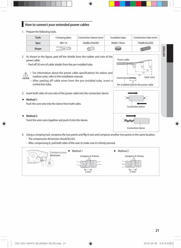
How to connect your extended power cables
1. Prepare the following tools.
Tools Crimping pliers Connection sleeve (mm) Insulation tape Contraction tube (mm)
Spec MH-14 20xØ6.5(HxOD) Width 19mm 70xØ8.0(LxOD)
Shape
2. As shown in the figure, peel off the shields from the rubber and wire of the power cable. - Peel off 20 mm of cable shields from the pre-installed tube.
• For information about the power cable specifications for indoor and outdoor units, refer to the installation manual.
• After peeling off cable wires from the pre-installed tube, insert a contraction tube.
(Unit: mm)
12060
202020
180
Power cable
20Pre-installed tube for the power cable
3. Insert both sides of core wire of the power cable into the connection sleeve.
Method 1Push the core wire into the sleeve from both sides.
Connection sleeve
Method 2Twist the wire cores together and push it into the sleeve.
Connection sleeve
4. Using a crimping tool, compress the two points and flip it over and compress another two points in the same location. - The compression dimension should be 8.0. - After compressing it, pull both sides of the wire to make sure it is firmly pressed.
C o m p r e s s i o n dimension
Method 1
Compress it 4 times.
5 mm
Method 2
Compress it 4 times.
5 mm
CAUTION
22
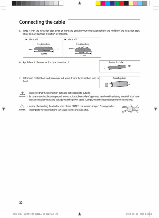
Connecting the cable5. Wrap it with the insulation tape twice or more and position your contraction tube in the middle of the insulation tape.
Three or more layers of insulation are required.
Method 1
40 mm
Insulation tape
Method 2
Insulation tape
35 mm
6. Apply heat to the contraction tube to contract it. Contraction tube
7. After tube contraction work is completed, wrap it with the insulation tape to finish.
Insulation tape
• Make sure that the connection parts are not exposed to outside.• Be sure to use insulation tape and a contraction tube made of approved reinforced insulating materials that have
the same level of withstand voltage with the power cable. (Comply with the local regulations on extensions.)
• In case of extending the electric wire, please DO NOT use a round-shaped Pressing socket.- Incomplete wire connections can cause electric shock or a fire.
CAUTION
WARNING

23
ENGLISH
Connecting the refrigerant pipeRefrigerant piping system
ItemsMaximum allowable length
Single installation
Type A B C
Applicable outdoor unit models AC024/030JXADCH AC036/042/048JXADCHAC030/036JXSCCH /
AC054KXADCH
Main pipe (L1) 164.0 ft (50 m) 246.0 ft (75 m)
Max. height difference between outdoor and indoor units (h1) 98.4 ft (30 m) 98.4 ft (30 m)
indoor
outdoor
L1
h1
Temper grade and minimum thickness of the refrigerant pipe
Outer diameter [inch] Minimum thickness [inch] Temper grade1/4 0.0276
C1220T-O3/8 0.0276
1/2 0.0315
5/8 0.0394
5/8 0.0315
C1220T-1/2H OR C1220T-H3/4 0.0354
7/8 0.0354
• Make sure to use C1220T-1/2H (Semi-hard) pipe for more than 3/4 in. In case of using C1220T-O (Soft) pipe for 3/4 in., pipe may be broken, which can result in an injury.CAUTION
Make at least one round:It will reduce noise and vibration
❋ The appearance of the unit may be different from the diagram depending on the model.
• After connecting pipes through the knock-out, cover the opening to prevent animals and debris from entering.CAUTION

24
Adding refrigerant (R-410A)The outdoor unit is loaded with sufficient refrigerant for standard piping. Thus, refrigerant must be added if the piping is lengthened. This operation can only be performed by a qualified refrigeration specialist. For volume of additional refrigerant, refer to “How to Calculate the Volume of Additional Refrigerant” section.1. Check that the stop valve is closed entirely.2. Charge the refrigerant through the service port of liquid stop valve.
• Do not charge the refrigerant through the gas side service port.NOTE
3. If you cannot charge the refrigerant according to the steps above, following these :1) Open both liquid stop valve and gas stop valve.2) Operate the air conditioner by pressing the K2 key on the outdoor unit PCB.3) About 30 minutes later, charge the refrigerant through the service port of gas stop valve.
• If necessary, refer to the pressure table classified by outdoor temperature.NOTE
1
Ref.
Gas side stop valve(service port)
Outdoor unit
Indoor unit
Balance Vacuum pump
Liquid side stop valve(service port)
How to Calculate the Volume of Additional RefrigerantThe volume of additional refrigerant is variable according to the length of the liquid pipe. Determine the liquid pipe length before adding refrigerant. This operation can only be performed by a qualified refrigeration specialist.
Single installation outdoor unit
ModelInterconnection pipe length
0 ~ 246 ft (0 ~ 75 m)
AC024JXADCH +0.108 oz/ft over 25.0 ft (+10 g/m over 7.5 m)
AC030JXADCH +0.237 oz/ft over 25.0 ft (+22 g/m over 7.5 m)
AC036JXADCH / AC042JXADCH / AC048JXADCH / AC054KXADCH +0.355 oz/ft over 25.0 ft (+33 g/m over 7.5 m)
AC030/036JXSCCH +0.269 oz/ft over 25.0 ft (+25 g/m over 7.5 m)

25
ENGLISH
Connecting to the system and removing air in the circuit• When installing, make sure there is no leakage. When recovering the refrigerant, ground the compressor before
removing the connection pipe. If the refrigerant pipe is not properly connected and the compressor operates with the service valve open, the pipe can inhale air and create abnormally high pressure inside of the refrigerant system that can cause explosion and injury.
CAUTION
The air in the indoor unit and in the pipe must be purged. If air remains in the refrigeration pipes, it will affect the compressor either reduce cooling/heating capacity or lead to a malfuction. Refrigerant for air purging is not charged in the outdoor unit. Use Vacuum Pump as shown at the right figure.1. Connect each assembly pipe to the appropriate valve on the outdoor unit and tighten the flare nut.
2. Referring to the illustration opposite, tighten the flare nut on section B first manually and then with a torque wrench, applying the following torque.
Outer Diameter (D) Torque (lbf • ft)ø6.35 mm(1/4") 10.3 ~ 13.3
ø9.52 mm(3/8") 25.0 ~ 31.0
ø12.70 mm(1/2") 36.1 ~ 45.0
ø15.88 mm(5/8") 50.2 ~ 60.5
ø19.05 mm(3/4") 73.8 ~ 88.5
3. Connect the low pressure charging hose of the manifold gauge to the gas pipe service valve port as shown in the figure.
• Make the electrical connection and leave the system into “stand by mode”. Do not turn on the system.
• This is necessary to speed up vacuum operation (full OPEN position of Electronic Expansion Valve - EEV -).
CAUTION
4. Open the valve of the low pressure side(A) of manifold gauge counterclockwise.
Outdoor unitA (Gas)
B (Liquid)
Vacuum pump
❋ The designs and shape are subject to change according to the model.
26
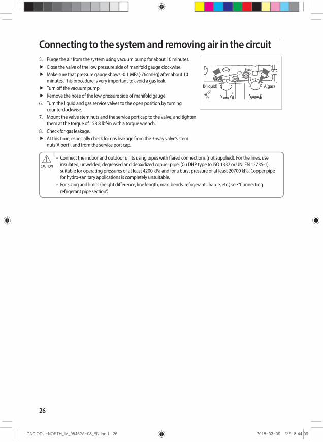
5. Purge the air from the system using vacuum pump for about 10 minutes.Close the valve of the low pressure side of manifold gauge clockwise.Make sure that pressure gauge shows -0.1 MPa(-76cmHg) after about 10 minutes. This procedure is very important to avoid a gas leak. Turn off the vacuum pump. Remove the hose of the low pressure side of manifold gauge.
6. Turn the liquid and gas service valves to the open position by turning counterclockwise.
7. Mount the valve stem nuts and the service port cap to the valve, and tighten them at the torque of 158.8 lbf•in with a torque wrench.
8. Check for gas leakage.At this time, especially check for gas leakage from the 3-way valve’s stem nuts(A port), and from the service port cap.
B(liquid) A(gas)
• Connect the indoor and outdoor units using pipes with flared connections (not supplied). For the lines, use insulated, unwelded, degreased and deoxidized copper pipe, (Cu DHP type to ISO 1337 or UNI EN 12735-1), suitable for operating pressures of at least 4200 kPa and for a burst pressure of at least 20700 kPa. Copper pipe for hydro-sanitary applications is completely unsuitable.
• For sizing and limits (height difference, line length, max. bends, refrigerant charge, etc.) see “Connecting refrigerant pipe section”.
CAUTION
Connecting to the system and removing air in the circuit

27
ENGLISH
Connecting the drain hose to the outdoor unitWhen using the air conditioner in the heating mode, ice may accumulate . During de-icing, the condensed water must be drained off safely. Consequently, you must install a drain hose on the outdoor unit, following the instructions below. (For AC030-036JXSCCH model, do not install a drain hose and a drain plug.)1. Provide 3.2 inches minimum between the bottom of the outdoor unit and the ground for installation.2. Insert the drain plug into the hole on the underside of the outdoor unit.3. Connect the drain hose to the drain plug.4. Ensure that the drained water runs off correctly and safely.
3.2 inch0.51 inch
5. Be sure to plug the rest of drain holes not connected with drain plugs using drain caps.
DRAIN CAP(5EA)DRAIN PLUG(2EA)
❋ When installing the product, make sure that the rack is not placed under the drain hole. ❋ If the product is installed in a region of heavy snow, allow enough separation distance between the product and the
ground.
• For AC030-036JXSCCH model, do not install a drain hose and a drain plug. - Let the water drain naturally.
• Ice may form on the ground. Take appropriate measures to prevent ice formation.
CAUTION
<Applicable model : AC030/036JXSCCH>

28
Cutting/Flaring the pipes1. Make sure that you have the required tools available. (pipe cutter, reamer, flaring tool and pipe holder)2. If you wish to shorten the pipes, cut it with a pipe cutter, taking care to ensure that the cut edge remains at a 90° angle
with the side of the pipe. Refer to the illustrations below for examples of edges cut correctly and incorrectly.
Oblique Rough Burr
3. To prevent any gas from leaking out, remove all burrs at the cut edge of the pipe, using a reamer.4. Slide a flare nut on to the pipe and modify the flare.
90°±
2° 45°±
2°
R 0.4~0.8 (0.016~0.032)
DL
Outer Diameter (D) Depth (A) Flare dimension (L)
ø6.35 mm(1/4") 0.051inch mm Inch
ø9.52 mm(3/8") 0.071inch 8.7~9.1 0.34~0.36
ø12.70 mm(1/2") 0.079inch 12.8~13.2 0.50~0.52
ø15.88 mm(5/8") 0.087inch 16.2~16.6 0.64~0.65
ø19.05 mm(3/4") 0.087inch 19.3~19.7 0.76~0.78
5. Check that the flaring is correct, referring to the illustrations below for examples of incorrect flaring.
Uneven Thickness
CrackedDamaged Surface
InclinedCorrect
6. Align the pipes and tighten the flare nuts first manually and then with a torque wrench, applying the following torque.
ValveFlare nut Valve cap Pressure port cap Valve needle Pressure port
Wrench(inch) lbf·ft Wrench(inch) lbf·ft Wrench(inch) lbf·ft Wrench(inch) lbf·ft Wrench(inch) lbf·ft1/4" 0.67 13.3 0.91
14.8
0.7111.8~ 13.9
Allen(Hex.)0.2
6.6
- 0.25
3/8" 0.87 31 0.91
1/2" 1.02 40.6 1.14
29.5 9.65/8" 1.14 48 1.14
3/4" 1.42 73.8 1.5
• If the pipes require brazing ensure that OFN(Oxygen Free Nitrogen) is flowing through the system.• Nitrogen blowing pressure range is 0.02 ~ 0.05 MPa.CAUTION

29
ENGLISH
Performing leak testsLEAK TEST WITH NITROGEN (before opening valves)In order to detect basic refrigerant leaks, before recreating the vacuum and recirculating the R-410A, it’s responsable of installer to pressurize the whole system with nitrogen (using a cylinder with pressure reducer) at a pressure above 40 bar / 580 PSI (gauge). LEAK TEST WITH R-410A (after the valves have been opened)Before opening valves, discharge all the nitrogen into the system and create vacuum. After opening valves check leaks using a leak detector for refrigerant R-410A.Once you have completed all the connections, check for possible leaks using leak detector specifically designed for HFC refrigerants.
A(Gas)B(Liquid)
❋ The designs and shape are subject to change according to the model.
To check for gas leaks on the Outdoor unitcheck the valves on section A and B with a leak detector.
Refrigerant pipe workOnce you have checked that there are no leaks in the system, you can insulate the piping and hose.
1. To avoid condensation problems, place an insulator around each refrigerant pipe.
• When insulate the pipe, be sure to overlap the insulation. NOTE
• When insulating the pipe, use non-slit insulator.CAUTION
NBR
2. Select the insulation of the refrigerant pipe.Insulate the gas side and liquid side pipe referring to the thickness according to the pipe size.Less than Indoor temperature of 86 °F and humidity of 85 % is the standard condition. If installing in a high humidity condition, use one grade thicker insulator by referring to the table below. If installing in an unfavorable conditions, use thicker one.Insulator’s heat-resistance temperature should be more than 248 °F.
Pipe Pipe size
Insulation Type (Heating/Cooling)
RemarksStandard [Less than 86 °F, 85 %]
High humidity [over 86 °F, 85 %]
EPDM, NBR (Unit : inch)
Liquid pipe1/4"~ 3/8" 0.35 t 0.35 t
Internal temperature is higher than 248 °F
1/2"~ 3/4" 0.51 t 0.51 t
Gas pipe1/4" 0.51 t 0.75 t
3/8" ~ 3/4" 0.75 t 0.98 t

30
When installing insulation in places and conditions below, use the same insulation that is used for high humidity conditions.<Geological condition> - High humidity places such as shoreline, hot spring, near lake or river, and ridge (when the part of the building is
covered by earth and sand.)<Operation purpose condition> - Restaurant ceiling, sauna, swimming pool etc.
<Building construction condition> - The ceiling frequently exposed to moisture and cooling is not covered.
e.g. The pipe installed at a corridor of a dormitory and studio or near an exit that opens and closes frequently. - The place where the pipe is installed is highly humid due to the lack of ventilation system.
• Make a hole (0.4 inch in diameter) on the insulation so that rain water can be drained in case it gets inside of the insulation. However, be careful not to damage the pipe. CAUTION
Using stop valve
To Open the Stop Valve
1. Open the cap and turn the stop valve counterclockwise by using a hexagonal wrench.
2. Turn it until the axis is stopped.
• Do not apply excessive force to the stop valve and always use special instruments. Otherwise, the stopping box can be damaged and the back sheet can leaks.
• If the watertight sheet leaks, turn the axis back by half, tighten the stopping box, then check the leakage again. If there is no leakage any more, tighten the axis entirely.
NOTE
3. Tighten the cap securely.
SpindleCharging Core
Tightening torque for body cap (Refer to the table)
Tightening torque for body cap (Refer to the table)
R-22: Thread of the screw - 7/16-20UNF R-410A: Thread of the screw - 1/2-20UNF
To Close the Stop Valve1. Remove the cap.2. Turn the stop valve clockwise by using a hexagonal wrench.3. Tighten the axis until the valve reached the sealing point.4. Tighten the cap securely.
• When you use the service port, always use a charging hose, too.• Check the leakage of refrigerant gas after tightening the cap.• Must use a spanner and wrench when you open/tighten the stop valve.
CAUTION
Refrigerant pipe work

31
ENGLISH
Interface module Installation (Optional)Accessories (Interface module : MIM-B14)
Interface module Interface module power cable
Interface module communication cable Installation Manual Case Cable-tie
1. Fix the case at with bolts on the side of the control box in the outdoor unit.(See the picture)2. Attach the Interface module PCB to the case in the control box in the outdoor unit, then connect the power and the
communication cable between the Interface module and the outdoor unit; refer to the figure of pages 18~19.3. If you install a Interface module to an outdoor unit, every indoor unit which is connected to an outdoor unit can be
controlled simultaneously.4. Each outdoor unit connected to the same centralized controller has its own Interface module.
Fix the case
32
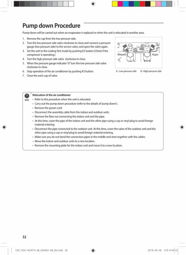
Pump down ProcedurePump down will be carried out when an evaporator is replaced or when the unit is relocated in another area.
1. Remove the cap from the low pressure side.2. Turn the low pressure side valve clockwise to close and connect a pressure
gauge (low pressure side) to the service valve, and open the valve again.3. Set the unit to the cooling Test mode by pushing K2 button (Check if the
compressor is operating.)4. Turn the high pressure side valve clockwise to close.5. When the pressure gauge indicates “0” turn the low pressure side valve
clockwise to close.6. Stop operation of the air conditioner by pushing K3 button.7. Close the each cap of valve.
B(liquid) A(gas)
A : Low pressure side B : High pressure side
Relocation of the air conditioner• Refer to this procedure when the unit is relocated.• Carry out the pump down procedure (refer to the details of ‘pump down’).• Remove the power cord.• Disconnect the assembly cable from the indoor and outdoor units.• Remove the flare nut connecting the indoor unit and the pipe.• At this time, cover the pipe of the indoor unit and the other pipe using a cap or vinyl plug to avoid foreign
material entering.• Disconnect the pipe connected to the outdoor unit. At this time, cover the valve of the outdoor unit and the
other pipe using a cap or vinyl plug to avoid foreign material entering.• Make sure you do not bend the connection pipes in the middle and store together with the cables.• Move the indoor and outdoor units to a new location.• Remove the mounting plate for the indoor unit and move it to a new location.
NOTE

33
ENGLISH
Checking correct groundingIf the power distribution circuit does not have a grounding or the grounding does not comply with specifications, an grounding electrode must be installed. The corresponding accessories are not supplied with the air conditioner.
1. Select an grounding electrode that complies with the specifications given in the illustration.
2. Connect the flexible hose to the flexible hose port. In damp hard soil rather than loose sandy or gravel soil that has a higher grounding resistance.Away from underground structures or facilities, such as gas pipes, water pipes, telephone lines and underground cables.At least two metres away from a lightening conductor grounding electrode and its cable.
• The grounding wire for the telephone line cannot be used to ground the air conditioner.NOTE
3. Finish wrapping insulating tape around the rest of the pipes leading to the outdoor unit.
Terminal M4
PVC-insulated green/ yellow wire
To grounding screw
Steel coreCarbon plastic
1.6 ft
1 ft
4. Install a green/yellow coloured grounding wire :If the grounding wire is too short, connect an extension lead, in a mechanical way and wrapping it with insulating tape (do not bury the connection).Secure the grounding wire in position with staples.
• If the grounding electrode is installed in an area of heavy traffic, its wire must be connected securely.NOTE
5. Carefully check the installation, by measuring the grounding resistance with a ground resistance tester. If the resistance is above required level, drive the electrode deeper into the ground or increase the number of grounding electrodes.
6. Connect the grounding wire to the electrical component box inside of the outdoor unit.

34
Testing operations1. Check the power supply between the outdoor unit and the auxiliary circuit breaker.
1 phase power supply : L1, L22. Check the indoor unit.
1) Check that you have connected the power and communication cables correctly. (If the power cable and communication cables one mixed up or connected incorrectly, the PCB will be damaged.)
2) Check the thermistor sensor, drain pump/hose, and display are connected correctly.3) KEY buttons are on Main PBA of Outdoor Unit.
3. Press K1 or K2 on the outdoor unit PCB to run the test mode and stop.
K1 Mode DISPLAY
1 Heating Test Mode
2 Defrost Test Mode
K2 Mode DISPLAY
1 Cooling Test Mode
2Inverter checker
(Load PBA inspection operation)
3 Pump down in Cool mode
Condition 1 : The outdoor temperature is under 50 °FCondition 2 : All the temperature conditions should meet the defrost conditions
4. After 12 minutes of stationary condition check each indoor unit air treatment :Cooling mode(indoor unit check) Inlet air temp. – Outlet air temp. ≥ 18 °F(reference only)Heating mode(indoor unit check) Inlet air temp. – Outlet air temp. ≥ 19.8 °F(reference only)In heating mode, the indoor fan motor can remain off to avoid cold air blown into conditioned space.
5. How to reset the power supply of the outdoor unit and deactivate the eco mode (standby mode) :Press [K3] button over 1 sec to reset the power supply of the outdoor unit and deactivate the eco mode (standby mode).
35
ENGLISH
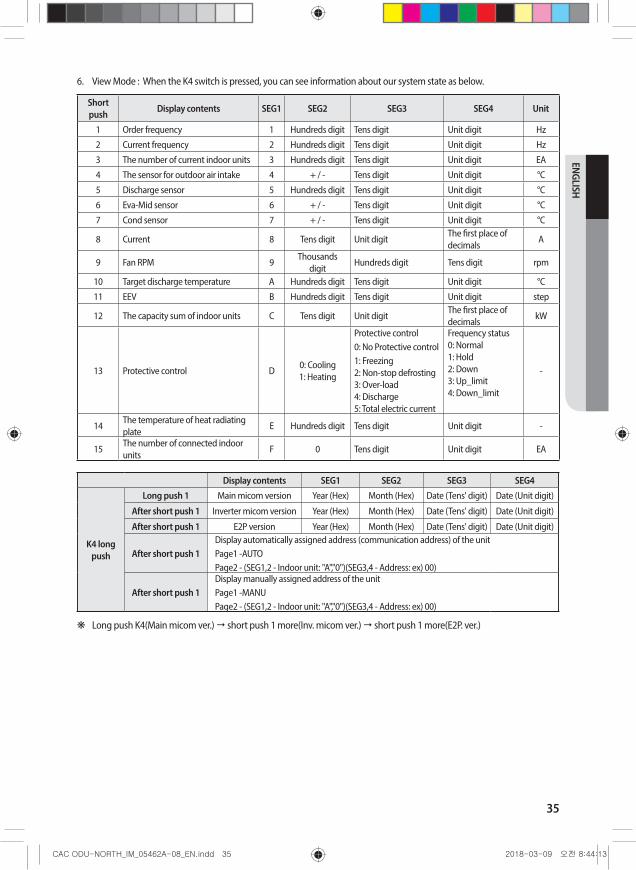
6. View Mode : When the K4 switch is pressed, you can see information about our system state as below.
Short push Display contents SEG1 SEG2 SEG3 SEG4 Unit
1 Order frequency 1 Hundreds digit Tens digit Unit digit Hz
2 Current frequency 2 Hundreds digit Tens digit Unit digit Hz
3 The number of current indoor units 3 Hundreds digit Tens digit Unit digit EA
4 The sensor for outdoor air intake 4 + / - Tens digit Unit digit °C
5 Discharge sensor 5 Hundreds digit Tens digit Unit digit °C
6 Eva-Mid sensor 6 + / - Tens digit Unit digit °C
7 Cond sensor 7 + / - Tens digit Unit digit °C
8 Current 8 Tens digit Unit digitThe first place of decimals
A
9 Fan RPM 9Thousands
digitHundreds digit Tens digit rpm
10 Target discharge temperature A Hundreds digit Tens digit Unit digit °C
11 EEV B Hundreds digit Tens digit Unit digit step
12 The capacity sum of indoor units C Tens digit Unit digitThe first place of decimals
kW
13 Protective control D0: Cooling 1: Heating
Protective control0: No Protective control1: Freezing 2: Non-stop defrosting 3: Over-load 4: Discharge 5: Total electric current
Frequency status 0: Normal 1: Hold 2: Down 3: Up_limit 4: Down_limit
-
14The temperature of heat radiating plate
E Hundreds digit Tens digit Unit digit -
15The number of connected indoor units
F 0 Tens digit Unit digit EA
Display contents SEG1 SEG2 SEG3 SEG4
K4 long push
Long push 1 Main micom version Year (Hex) Month (Hex) Date (Tens' digit) Date (Unit digit)
After short push 1 Inverter micom version Year (Hex) Month (Hex) Date (Tens' digit) Date (Unit digit)
After short push 1 E2P version Year (Hex) Month (Hex) Date (Tens' digit) Date (Unit digit)
After short push 1Display automatically assigned address (communication address) of the unitPage1 -AUTOPage2 - (SEG1,2 - Indoor unit: "A","0")(SEG3,4 - Address: ex) 00)
After short push 1Display manually assigned address of the unitPage1 -MANUPage2 - (SEG1,2 - Indoor unit: "A","0")(SEG3,4 - Address: ex) 00)
❋ Long push K4(Main micom ver.) short push 1 more(Inv. micom ver.) short push 1 more(E2P. ver.)
36
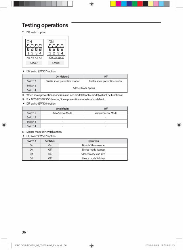
7. DIP switch option
ON
1 2 3 4K5 K6 K7 K8
ON
1 2 3 4K9K10 K11 K12
SW507 SW508
DIP switch(SW507) option
On (default) Off
Switch 2 Disable snow prevention control Enable snow prevention control
Switch 3Silence Mode option
Switch 4
❋ When snow prevention mode is in use, eco mode(standby mode)will not be functional. ❋ For AC030/036JXSCCH model, Snow prevention mode is set as default.
DIP switch(SW508) option
On(default) OffSwitch 1 Auto Silence Mode Manual Silence Mode
Switch 2 - -
Switch 3 - -
Switch 4 - -
8. Silence Mode DIP switch optionDIP switch(SW507) option
Switch 3 Switch 4 OperationOn On Disable Silence mode
On Off Silence mode 1st step
Off On Silence mode 2nd step
Off Off Silence mode 3rd step
Testing operations

37
ENGLISH
Installing the wind baffle If you operate the cooling operation of air conditioner in the condition where ambient temperature is lower than 23 °F DB(Dry bulb), or the outdoor unit might be faced with strong wind directly, the wind baffle should be installed to prevent the outdoor unit fan from operating in reverse way.
❋ Wind baffle is not supplied with the product.
Make holes on both sides and attach the wind baffle using screws.
Make holes on both sides and attach the wind baffle using screws.
24.6 inch0.63 inch
Partition
<Front View>
"A" "A"
<Top Down View>“A” – Should be 7 7/8 inch or longer
• When attaching the wind baffle using screws, be careful that the screws do not damage the partition and the heat exchanger.CAUTION
• Install outdoor units with the back surface facing wall side to eliminate the effects of external wind.NOTE

38
TroubleshootingThe table below list the self-diagnostic routines. For some of error codes, you must contact an authorized service centre.If an error occurs during the operation, it is displayed on the outdoor unit PCB LED, both MAIN PCB and INVERTER PCB.
No. Error Code Meaning Remarks
1 E108 Error due to duplicated communication address Check on repeated indoor unit main address
2 E121Error on room temperature sensor of indoor unit (Short or Open)
Indoor unit Room Thermistor Open/Short
3 E122 Error on EVA IN sensor of indoor unit (Short or Open) Indoor unit EVA_IN Thermistor Open/Short
4 E123 Error on EVA OUT sensor of indoor unit (Short or Open)Indoor unit EVA_OUT Thermistor Open/Short
5 E153 Error on float switch (2nd detection)Indoor unit Float Switch Open/Short Drain Pump operation Check
6 E154 Indoor fan error Check on indoor unit indoor Fan operation
7 E164Error due to connecting outdoor units that do not support the Wind-Free function
Check outdoor main PBA S/W, Check outdoor EEPROM data
8 E198 Error on thermal fuse of indoor unit (Open)Thermal Fuse Open Check of indoor unit Terminal Block
9 E201
Communication error between the indoor unit and outdoor unit (Pre-tracking failure or when the actual number of indoor units are different from the indoor unit quantity setting on the outdoor unit)Error due to communication tracking failure after initial power is supplied (The error occurs regardless of the number of units.)
Check indoor quantity setting in outdoor
10 E202Communication error between indoor unit and outdoor unit (When there is no response from indoor units after tracking is completed)
Check electrical connection and setting between indoor unit and outdoor unit
11 E203Communication error between the outdoor unit and main micom (For PF #4 to #6 controllers, error will be determined from the time when the compressor is turned on.)
Check electrical connection and setting between outdoor unit MAIN PBA - INVERTER PBA
12 E221 Error on outdoor temperature sensor (Short or Open) Check Outdoor sensor Open / Short
13 E231 Error on outdoor COND OUT sensor (Short or Open) Check Cond-Out sensor Open / Short
14 E251Error on discharge temperature sensor of compressor 1 (Short or Open)
Check Discharge sensor Open / Short
15 E320 Error on OLP sensor (Short or Open) Check OLP sensor Open / Short
16 E403 Compressor down due to freeze protection control Check Outdoor Cond.
17 E404 System stop due to overload protection control Check Comp. when it starts
18 E416 System stop due to discharge temperature -
19 E422 Blockage detected on high pressure pipe
1. Check if the service valve is open2. Check for refrigerant leakage (pipe
connections, heat exchanger) and charge refrigerant if necessary
3. Check if there's any blockage on the refrigerant cycle (indoor unit/outdoor unit)
4. Check if additional refrigerant has been added after pipe extension
20 E425 Reverse phase or open phaseCheck whether 3 phase is reversed or opened.

39
ENGLISH
No. Error Code Meaning Remarks
21 E440Heating operation restricted at outdoor temperature over Theat_high value (default:30°C)
1. Check the range of temperature limited for heating operation
2.Check the outdoor temperature sensor
22 E441Cooling operation restricted at outdoor temperature below Tcool_low value (default:0°C)
1. Check the range of temperature limited for cooling operation
2. Check the outdoor temperature sensor
23 E458 Fan speed error FAN1 ERROR
24 E461 Error due to operation failure of inverter compressor -
25 E462 System stop due to full current control -
26 E463 Over current trip / PFC over current error Check OLP sensor
27 E464 IPM Over Current(O.C)
1. Check if the service valve is open2. Check the state of refrigerant3. Check if connecting wire and the pipe are OK4. Check the compressor
28 E465 Comp. Over load error -
29 E466 DC-Link voltage under/over error Check AC Power and DC Link Voltage
30 E467Error due to abnormal rotation of the compressor or unconnected wire of compressor
Check Comp wire
31 E468 Error on current sensor (Short or Open) Check Outdoor Inverter PBA.
32 E469 Error on DC-Link voltage sensor (Short or Open) -
33 E470 Outdoor unit EEPROM Read/Write error (Option) Check Outdoor EEPROM Data
34 E471 Outdoor unit EEPROM Read/Write error (H/W) Check Outdoor EEPROM PBA
35 E474 Error on IPM Heat Sink sensor of inverter 1 (Short or Open) Check Outdoor Inverter PBA.
36 E475 Error on inverter fan 2 FAN2 ERROR
37 E483 Overvoltage of H/W detect DC link Check AC Power
38 E484 PFC Overload (Over current) Error Check Outdoor Inverter PBA.
39 E485 Error on input current sensor of inverter 1 (Short or Open) Check Outdoor EEPROM PBA
40 E488 Inverter input voltage sensor error Check Outdoor Inverter PBA
41 E500 IPM over heat error on inverter 1 Check Outdoor Inverter PBA.
42 E508 Smart install is not installed -
43 E554 Gas leak detected Check the refrigerant
44 E556Error due to mismatching capacity of indoor and outdoor unit
Check the indoor and outdoor unit capacity
45 E557 DPM remote controller option error Check the indoor option code
46 E590 Inverter EEPROM Checksum error -
