caution warning warning
TRANSCRIPT

APPLICATION REQUIREMENTS: Available to all commercial door operators using the Logic 5 control board.
LOGIC BOARD (L5)REPLACEMENT KIT
K001D8075-1
INSTALLATION
To avoid SERIOUS personal INJURY or DEATH from electrocution, DISCONNECT electrical power to operator BEFORE proceeding.
ATTENTION
AVERTISSEMENT AVERTISSEMENT
AVERTISSEMENT
WARNING
CAUTION
WARNING
WARNING WARNING
PRECAUCIÓN ADVERTENCIA
ADVERTENCIA ADVERTENCIA
REMOVE EXISTING BOARD1. Disconnect power to operator.2. Remove all wires from the existing board: • Control Wiring Terminal Block • System Wiring Connector (J3)NOTE: Remember location of all wiring connections for reinstallation.3. Remove the coaxial cable from the board F connector.4. Remove any installed option cards from their corresponding
slots from the board.5. Remove the board from its four mounting posts.
WIRING POWER AND CONNECTION SETTINGSBefore matching any connection settings, make sure the power supply is the correct voltage, phase, frequency, and amperage compatible with your operator.1. Remove the new board from the protective bag.2. Match settings from existing board to the new board: • 1-Phase and 3-Phase Jumper
For 3-Phase Operators Only: DO NOT move the 3-Phase jumper until installation and specifi ed instructions following Step 6 are completed.
• Motor Direction Jumper • Selector DialNOTE: The following information is stored within the fi rmware and will need to be re-programmed if the fi rmware is upgraded with the board: • All Remote Controls (On Board Receiver Only) • Timer-to-Close • Maximum Run Timer • Maintenance Alert System • Up and Down Mid Stops • Pre-Warning Timer when the TLSCARD option card is used • Dynamic Brake for models N4/N4X only when AUXCARD is
used.
INSTALL NEW BOARD1. Place the new board into the operator. Position the board onto
mounting posts pressing firmly to ensure posts are completely through mounting holes.
2. Reconnect the coaxial cable to the board F connector.3. Reconnect all wires to the main board control wiring terminal
block.4. Install all option cards into the slots on the board.5. Make sure the electrical box is clear of all debris and tools.
6. Reconnect power to the operator and verify operation.
3-PHASE OPERATORS ONLY NOTE: DO NOT activate the operator until the following steps
have been completed: 1. Turn the SELECTOR DIAL to PROG (programming). 2. Move the PHASE jumper from the 1-Phase position to the
3-Phase position. 3. Return the SELECTOR DIAL to desired mode of operation.
Refer to pages 3-10 for programming and settings as necessary.
SPECIAL PROGRAMMING IS REQUIRED FOR N4/N4X MODELS USING AN AUXCARD. THIS SETS THE DYNAMIC BRAKE FOR THE MOTOR. FOLLOW THESE INSTRUCTIONS PRIOR TO RUNNING THE OPERATOR.1. Turn the SELECTOR DIAL to OPTN.2. Press and release the MAS button.3. Press and release the MID button. The MAS LED will blink 6 times.4. Turn SELECTOR DIAL back to desired wiring type.
2
INTRODUCTION TO PROGRAMMING
SLO
T 1
RADIO
SLS
MRT MID TTC
DATA
24VAC
24VAC
LMEP:
EDGE:
OPEN
CLOSE
STOP
COMMON
RELAY A
RELAY B
SBC 1
2
3
4
5
6
7
8
9
10
11
12
13
14
MAS
COMMON
TIMERDEFEAT
POWER
TIMERENABLE
1 2 3
FSTS
DIAG
OPTN
PROG
T TSE2
D1
C2
B2
CLS
OLS
MID
RE
V
ST
D
SLO
T 2
MO
TO
RD
IRE
CT
ION
3-PH
AS
E
1-PH
AS
E
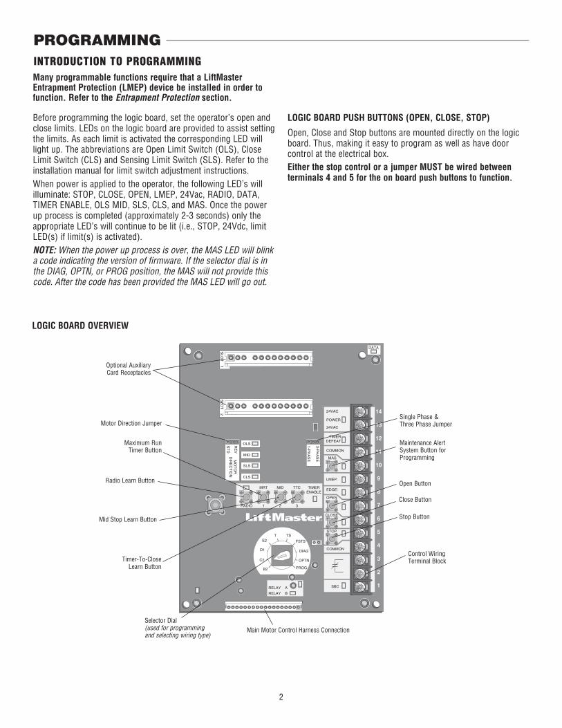
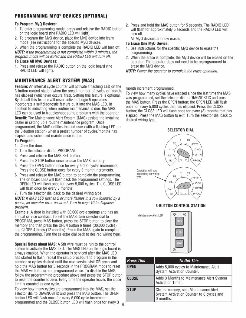
Selector Dial(used for programming and selecting wiring type)
Main Motor Control Harness Connection
Maximum Run Timer Button
Optional Auxiliary Card Receptacles
Mid Stop Learn Button
Timer-To-Close Learn Button
Radio Learn Button Open Button
Close Button
Stop Button
Control Wiring Terminal Block
Motor Direction Jumper
Maintenance Alert System Button for Programming
Single Phase & Three Phase Jumper
PROGRAMMING
LOGIC BOARD OVERVIEW
LOGIC BOARD PUSH BUTTONS (OPEN, CLOSE, STOP)
Open, Close and Stop buttons are mounted directly on the logic board. Thus, making it easy to program as well as have door control at the electrical box. Either the stop control or a jumper MUST be wired between terminals 4 and 5 for the on board push buttons to function.
Before programming the logic board, set the operator’s open and close limits. LEDs on the logic board are provided to assist setting the limits. As each limit is activated the corresponding LED will light up. The abbreviations are Open Limit Switch (OLS), Close Limit Switch (CLS) and Sensing Limit Switch (SLS). Refer to the installation manual for limit switch adjustment instructions.When power is applied to the operator, the following LED’s will illuminate: STOP, CLOSE, OPEN, LMEP, 24Vac, RADIO, DATA,TIMER ENABLE, OLS MID, SLS, CLS, and MAS. Once the power up process is completed (approximately 2-3 seconds) only the appropriate LED’s will continue to be lit (i.e., STOP, 24Vdc, limit LED(s) if limit(s) is activated).NOTE: When the power up process is over, the MAS LED will blink a code indicating the version of fi rmware. If the selector dial is in the DIAG, OPTN, or PROG position, the MAS will not provide this code. After the code has been provided the MAS LED will go out.
Many programmable functions require that a LiftMaster Entrapment Protection (LMEP) device be installed in order to function. Refer to the Entrapment Protection section.
3
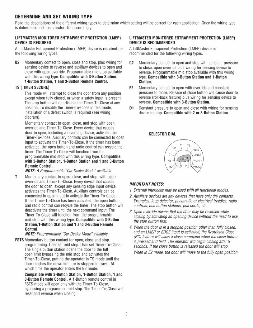
DETERMINE AND SET WIRING TYPERead the descriptions of the different wiring types to determine which setting will be correct for each application. Once the wiring type is determined, set the selector dial accordingly.
OPTN
PROG
DIAG
FSTS
TSTE2
D1
C2
B2
SELECTOR DIAL
IMPORTANT NOTES:1. External interlocks may be used with all functional modes.2. Auxiliary devices are any devices that have only dry contacts.
Examples: loop detector, pneumatic or electrical treadles, radio controls, one button stations, pull cords, etc.
3. Open override means that the door may be reversed while closing by activating an opening device without the need to use the stop button first.
4. When the door is in a stopped position other than fully closed, and an LMEP or EDGE input is activated, the Restricted Close (RC) feature will allow a close command when the close button is pressed and held. The operator will begin closing after 5 seconds. If the close button is released the door will stop.
When in E2 mode, the door will move to the fully open position.
LIFTMASTER MONITORED ENTRAPMENT PROTECTION (LMEP) DEVICE IS REQUIREDA LiftMaster Entrapment Protection (LMEP) device is required for the following wiring types.
LIFTMASTER MONITORED ENTRAPMENT PROTECTION (LMEP) DEVICE IS RECOMMENDEDA LiftMaster Entrapment Protection (LMEP) device is recommended for the following wiring types.
B2 Momentary contact to open, close and stop, plus wiring for sensing device to reverse and auxiliary devices to open and close with open override. Programmable mid stop available with this wiring type. Compatible with 3-Button Station, 1-Button Station, 1 and 3-Button Remote Control.
TS (TIMER SECURE) This mode will attempt to close the door from any position
except when fully closed, or when a safety input is present. The stop button will not disable the Timer-To-Close at any position. To disable the Timer-To-Close in this mode, installation of a defeat switch is required (see wiring diagram).
Momentary contact to open, close, and stop with open override and Timer-To-Close. Every device that causes door to open, including a reversing device, activates the Timer-To-Close. Auxiliary controls can be connected to open input to activate the Timer-To-Close. If the timer has been activated, the open button and radio control can recycle the timer. The Timer-To-Close will function from the programmable mid stop with this wiring type. Compatible with 3-Button Station, 1-Button Station and 1 and 3-Button Remote Control.NOTE: A Programmable “Car Dealer Mode” available.
T Momentary contact to open, close, and stop, with open override and Timer-To-Close. Every device that causes the door to open, except any sensing edge input device, activates the Timer-To-Close. Auxiliary controls can be connected to open input to activate the Timer-To-Close. If the Timer-To-Close has been activated, the open button and radio control can recycle the timer. The stop button will deactivate the timer until the next command input. The Timer-To-Close will function from the programmable mid stop with this wiring type. Compatible with 3-Button Station,1-Button Station and 1 and 3-Button Remote Control. NOTE: Programmable “Car Dealer Mode” available.
FSTS Momentary button contact for open, close and stop programming. User set mid stop. User set Timer-To-Close. The single button station opens the door to the full open limit bypassing the mid stop and activates the Timer-To-Close, putting the operator in TS mode until the door reaches the down limit, or is stopped in travel. At which time the operator enters the B2 mode.
Compatible with 3-Button Station, 1-Button Station, 1 and 3-Button Remote Control. A 1-Button remote control in FSTS mode will open only with the Timer-To-Close, bypassing a programmed mid stop. The Timer-To-Close willreset and reverse when closing.
C2 Momentary contact to open and stop with constant pressure to close, open override plus wiring for sensing device to reverse. Programmable mid stop available with this wiring type. Compatible with 3-Button Station and 1-Button Station.
E2 Momentary contact to open with override and constant pressure to close. Release of close button will cause door to reverse (roll-back feature) plus wiring for sensing device to reverse. Compatible with 3-Button Station.
D1 Constant pressure to open and close with wiring for sensing device to stop. Compatible with 2 or 3-Button Station.
4
Built in 3-channel, Security✚ 2.0™ radio receiver that allows you to add up to 90 remote control devices and up to 30 keyless entry devices.NOTE: The following programming requires a LiftMaster Monitored Entrapment Protection (LMEP) device.
STANDARD REMOTE CONTROL
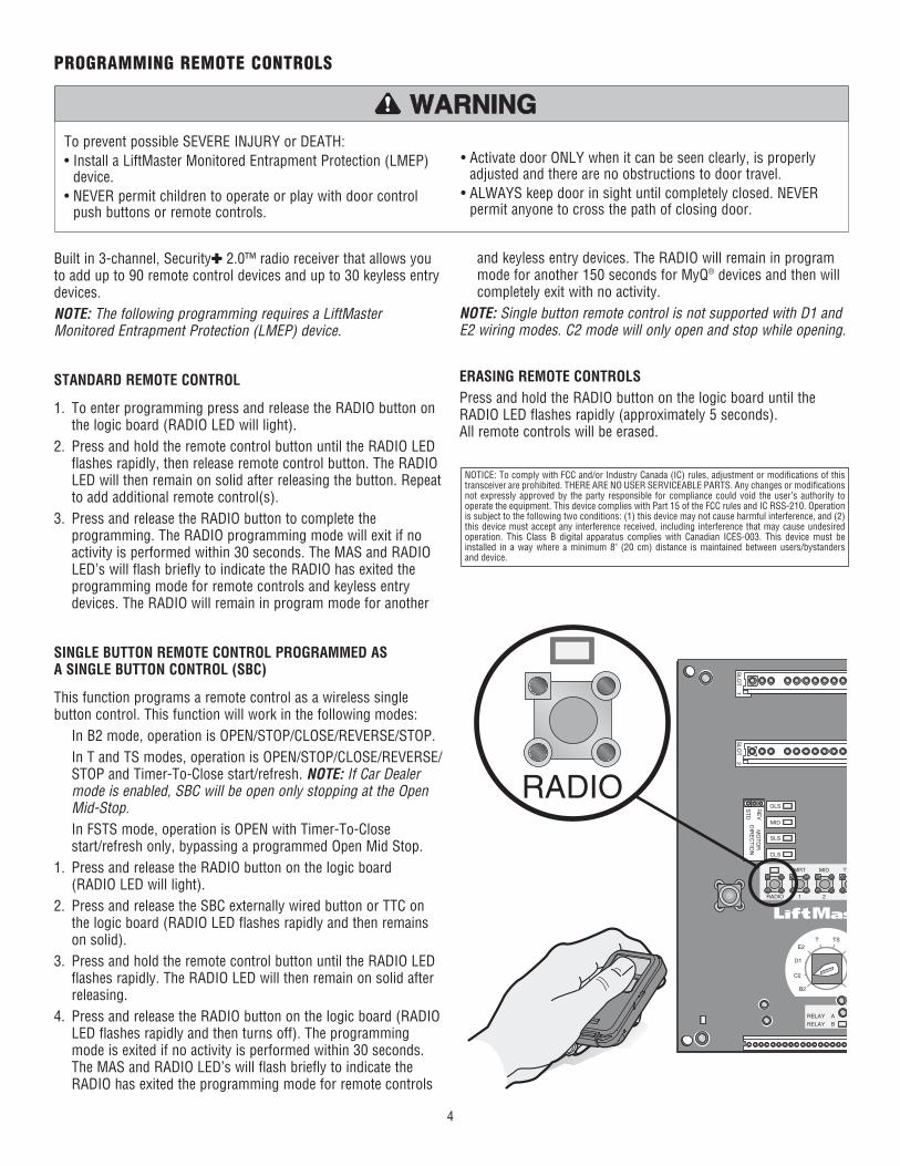
1. To enter programming press and release the RADIO button on the logic board (RADIO LED will light).
2. Press and hold the remote control button until the RADIO LED flashes rapidly, then release remote control button. The RADIO LED will then remain on solid after releasing the button. Repeat to add additional remote control(s).
3. Press and release the RADIO button to complete the programming. The RADIO programming mode will exit if no activity is performed within 30 seconds. The MAS and RADIO LED’s will flash briefly to indicate the RADIO has exited the programming mode for remote controls and keyless entry devices. The RADIO will remain in program mode for another
SINGLE BUTTON REMOTE CONTROL PROGRAMMED AS A SINGLE BUTTON CONTROL (SBC)
This function programs a remote control as a wireless single button control. This function will work in the following modes: In B2 mode, operation is OPEN/STOP/CLOSE/REVERSE/STOP. In T and TS modes, operation is OPEN/STOP/CLOSE/REVERSE/
STOP and Timer-To-Close start/refresh. NOTE: If Car Dealer mode is enabled, SBC will be open only stopping at the Open Mid-Stop.
In FSTS mode, operation is OPEN with Timer-To-Close start/refresh only, bypassing a programmed Open Mid Stop.
1. Press and release the RADIO button on the logic board(RADIO LED will light).
2. Press and release the SBC externally wired button or TTC on the logic board (RADIO LED flashes rapidly and then remains on solid).
3. Press and hold the remote control button until the RADIO LED flashes rapidly. The RADIO LED will then remain on solid after releasing.
4. Press and release the RADIO button on the logic board (RADIO LED flashes rapidly and then turns off). The programming mode is exited if no activity is performed within 30 seconds. The MAS and RADIO LED’s will flash briefly to indicate the RADIO has exited the programming mode for remote controls
PROGRAMMING REMOTE CONTROLS
To prevent possible SEVERE INJURY or DEATH:• Install a LiftMaster Monitored Entrapment Protection (LMEP)
device.• NEVER permit children to operate or play with door control
push buttons or remote controls.
• Activate door ONLY when it can be seen clearly, is properly adjusted and there are no obstructions to door travel.
• ALWAYS keep door in sight until completely closed. NEVER permit anyone to cross the path of closing door.
ATTENTION
AVERTISSEMENT AVERTISSEMENT
AVERTISSEMENT
WARNING WARNING
CAUTION
WARNING
WARNING
PRECAUCIÓN ADVERTENCIA
ADVERTENCIA ADVERTENCIA
SLO
T 1
RADIO
SLS
MRT MID TT
RELAY A
RELAY B
1 2 3
F
P
T TSE2
D1
C2
B2
CLS
OLS
MID
RE
V
ST
D
SLO
T 2
MO
TO
RD
IRE
CT
ION
RADIO
and keyless entry devices. The RADIO will remain in program mode for another 150 seconds for MyQ® devices and then will completely exit with no activity.
NOTE: Single button remote control is not supported with D1 and E2 wiring modes. C2 mode will only open and stop while opening.
ERASING REMOTE CONTROLSPress and hold the RADIO button on the logic board until the RADIO LED flashes rapidly (approximately 5 seconds).All remote controls will be erased.
NOTICE: To comply with FCC and/or Industry Canada (IC) rules, adjustment or modifications of this transceiver are prohibited. THERE ARE NO USER SERVICEABLE PARTS. Any changes or modifications not expressly approved by the party responsible for compliance could void the user’s authority to operate the equipment. This device complies with Part 15 of the FCC rules and IC RSS-210. Operation is subject to the following two conditions: (1) this device may not cause harmful interference, and (2) this device must accept any interference received, including interference that may cause undesired operation. This Class B digital apparatus complies with Canadian ICES-003. This device must be installed in a way where a minimum 8" (20 cm) distance is maintained between users/bystanders and device.
5
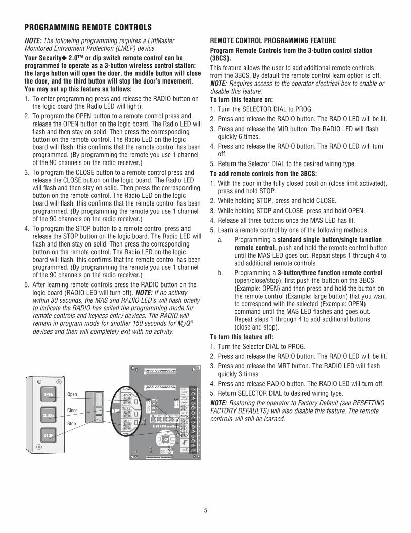
NOTE: The following programming requires a LiftMaster Monitored Entrapment Protection (LMEP) device.Your Security✚ 2.0™ or dip switch remote control can be programmed to operate as a 3-button wireless control station: the large button will open the door, the middle button will close the door, and the third button will stop the door’s movement. You may set up this feature as follows:1. To enter programming press and release the RADIO button on
the logic board (the Radio LED will light).2. To program the OPEN button to a remote control press and
release the OPEN button on the logic board. The Radio LED will flash and then stay on solid. Then press the corresponding button on the remote control. The Radio LED on the logic board will flash, this confirms that the remote control has been programmed. (By programming the remote you use 1 channel of the 90 channels on the radio receiver.)
3. To program the CLOSE button to a remote control press and release the CLOSE button on the logic board. The Radio LED will flash and then stay on solid. Then press the corresponding button on the remote control. The Radio LED on the logic board will flash, this confirms that the remote control has been programmed. (By programming the remote you use 1 channel of the 90 channels on the radio receiver.)
4. To program the STOP button to a remote control press and release the STOP button on the logic board. The Radio LED will flash and then stay on solid. Then press the corresponding button on the remote control. The Radio LED on the logic board will flash, this confirms that the remote control has been programmed. (By programming the remote you use 1 channel of the 90 channels on the radio receiver.)
5. After learning remote controls press the RADIO button on the logic board (RADIO LED will turn off). NOTE: If no activity within 30 seconds, the MAS and RADIO LED’s will flash briefly to indicate the RADIO has exited the programming mode for remote controls and keyless entry devices. The RADIO will remain in program mode for another 150 seconds for MyQ ® devices and then will completely exit with no activity.
SLO
T 1
RADIO
SLS
MRT MID TTC
DATA
24VAC
24VAC
LMEP:
EDGE:
OPEN
CLOSE
STOP
COMMON
RELAY A
RELAY B
SBC 1
2
3
4
5
6
7
8
9
10
11
12
13
14
MAS
COMMON
TIMERDEFEAT
POWER
TIMERENABLE
1 2 3
FSTS
DIAG
OPTN
PROG
T TSE2
D1
C2
B2
CLS
OLS
MID
RE
V
ST
D
SLO
T 2
MO
TO
RD
IRE
CT
ION
3-PH
AS
E
1-PH
AS
E
EDGE:
OPEN
CLOSE
STOP
COMMON
MERNABLE
OPEN
CLOSE
STOP
Open
Close
Stop
REMOTE CONTROL PROGRAMMING FEATUREProgram Remote Controls from the 3-button control station (3BCS).This feature allows the user to add additional remote controls from the 3BCS. By default the remote control learn option is off. NOTE: Requires access to the operator electrical box to enable or disable this feature.To turn this feature on:1. Turn the SELECTOR DIAL to PROG.2. Press and release the RADIO button. The RADIO LED will be lit.3. Press and release the MID button. The RADIO LED will flash
quickly 6 times.4. Press and release the RADIO button. The RADIO LED will turn
off.5. Return the Selector DIAL to the desired wiring type.To add remote controls from the 3BCS:1. With the door in the fully closed position (close limit activated),
press and hold STOP.2. While holding STOP, press and hold CLOSE.3. While holding STOP and CLOSE, press and hold OPEN.4. Release all three buttons once the MAS LED has lit.5. Learn a remote control by one of the following methods: a. Programming a standard single button/single function
remote control, push and hold the remote control button until the MAS LED goes out. Repeat steps 1 through 4 to add additional remote controls.
b. Programming a 3-button/three function remote control (open/close/stop), first push the button on the 3BCS (Example: OPEN) and then press and hold the button on the remote control (Example: large button) that you want to correspond with the selected (Example: OPEN) command until the MAS LED flashes and goes out. Repeat steps 1 through 4 to add additional buttons (close and stop).
To turn this feature off:1. Turn the Selector DIAL to PROG.2. Press and release the RADIO button. The RADIO LED will be lit.3. Press and release the MRT button. The RADIO LED will flash
quickly 3 times.4. Press and release RADIO button. The RADIO LED will turn off.5. Return SELECTOR DIAL to desired wiring type.NOTE: Restoring the operator to Factory Default (see RESETTING FACTORY DEFAULTS) will also disable this feature. The remote controls will still be learned.
PROGRAMMING REMOTE CONTROLS
6
OPTN
PROG
DIAG
FSTS
TSTE2
D1
C2
B2
MAINTENANCE ALERT SYSTEM (MAS)Feature: An internal cycle counter will activate a flashing LED on the 3-button control station when the preset number of cycles or months has elapsed (whichever occurs first). Setting this feature is optional. By default this feature will never activate. Logic 5 operators incorporate a self diagnostic feature built into the MAS LED. In addition to indicating when routine maintenance is due, the MAS LED can be used to troubleshoot some problems with the operator.Benefit: The Maintenance Alert System (MAS) assists the installing dealer in setting up a routine maintenance program. Once programmed, the MAS notifies the end user (with a flashing LED on the 3-button station) when a preset number of cycles/months has elapsed and scheduled maintenance is due.To Program:1. Close the door.2. Turn the selector dial to PROGRAM.3. Press and release the MAS SET button.4. Press the STOP button once to clear the MAS memory.5. Press the OPEN button once for every 5,000 cycles increments.
Press the CLOSE button once for every 3 month increments. 6. Press and release the MAS button to complete the programming.
The on board LED will flash back the programmed settings. The OPEN LED will flash once for every 5,000 cycles. The CLOSE LED will flash once for every 3 months.
7. Turn the selector dial back to the desired wiring type.NOTE: If MAS LED flashes 2 or more flashes in a row followed by a pause, an operator error occurred. Turn to page 10 to diagnose problem.Example: A door is installed with 30,000 cycle springs and has an annual service contract. To set the MAS, turn selector dial to PROGRAM, press MAS button, press the STOP button to clear the memory and then press the OPEN button 6 times (30,000 cycles) and CLOSE 4 times (12 months). Press the MAS again to complete the programming. Turn the selector dial back to desired wiring type.
Special Notes about MAS: A 5th wire must be run to the control station to activate the MAS LED. The MAS LED on the logic board is always enabled. When the operator is serviced after the MAS LED has started to flash, repeat the setup procedure to program in the number or cycles desired until the next service visit OR press and hold the MAS button for 5 seconds in the PROGRAM mode to reset the MAS with its current programmed value. To disable the MAS, follow the programming procedure above and press the STOP button to reset the counter to zero. Every time the operator leaves the close limit is counted as one cycle.To view how many cycles are programmed into the MAS, set the selector dial to DIAGNOSTIC and press the MAS button. The OPEN button LED will flash once for every 5,000 cycle increment programmed and the CLOSE button LED will flash once for every 3
SELECTOR DIAL
OPEN
CLOSE
STOP
Adds 5,000 cycles to Maintenance Alert System Activation Counter.
Adds 3 Months to Maintenance Alert System Activation Timer.
Clears memory, sets Maintenance Alert System Activation Counter to 0 cycles and0 months.
Press This To Get This
3-BUTTON CONTROL STATION
OPEN
CLOSE
STOP
Maintenance Alert LED
Operation will vary depending on wiring type
OPTN
PROG
DIAG
FSTS
TSTE2
D1
C2
B2
To Program MyQ Devices:1. To enter programming mode, press and release the RADIO button
on the logic board (the RADIO LED will light).2. To program the MyQ device, place the MyQ device into learn
mode (see instructions for the specific MyQ device).3. When the programming is complete the RADIO LED will turn off.NOTE: If the programming is not completed within 3 minutes, the program mode will be exited and the RADIO LED will turn off.To Erase All MyQ Devices:1. Press and release the RADIO button on the logic board (the
RADIO LED will light).
2. Press and hold the MAS button for 5 seconds. The RADIO LED will flash for approximately 5 seconds and the RADIO LED will turn off.
All MyQ devices are now erased.To Erase One MyQ Device:1. See instructions for the specific MyQ device to erase the
programming.2. When the erase is complete, the MyQ device will be erased on the
operator. The operator does not need to be reprogrammed to erase the MyQ device.
NOTE: Power the operator to complete the erase operation.
month increment programmed.To view how many cycles have elapsed since the last time the MAS was programmed, set the selector dial to DIAGNOSTIC and press the MAS button. Press the OPEN button; the OPEN LED will flash once for every 5,000 cycles that has elapsed. Press the CLOSE button; the CLOSE LED will flash once for every (3) months that has elapsed. Press the MAS button to exit. Turn the selector dial back to desired wiring type.
PROGRAMMING MYQ® DEVICES (OPTIONAL)
7
OPTN
PROG
DIAG
FSTS
TSTE2
D1
C2
B2
OPTN
PROG
DIAG
FSTS
TSTE2
D1
C2
B2
SELECTOR DIAL
Operation will vary depending on wiring type
SELECTOR DIAL
To prevent possible SEVERE INJURY or DEATH:• Install a LiftMaster Monitored Entrapment Protection (LMEP)
device.• NEVER permit children to operate or play with door control
push buttons or remote controls.
• Activate door ONLY when it can be seen clearly, is properly adjusted and there are no obstructions to door travel.
• ALWAYS keep door in sight until completely closed. NEVER permit anyone to cross path of closing door.
ATTENTION
AVERTISSEMENT AVERTISSEMENT
AVERTISSEMENT
WARNING WARNING
CAUTION
WARNING
WARNING
PRECAUCIÓN ADVERTENCIA
ADVERTENCIA ADVERTENCIA
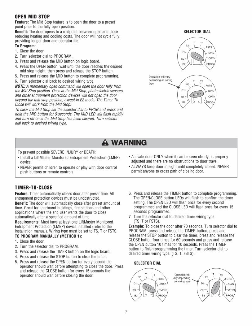
OPEN MID STOPFeature: The Mid Stop feature is to open the door to a preset point prior to the fully open position.Benefit: The door opens to a midpoint between open and close reducing heating and cooling costs. The door will not cycle fully, providing longer door and operator life.To Program:1. Close the door.2. Turn selector dial to PROGRAM.3. Press and release the MID button on logic board.4. Press the OPEN button, wait until the door reaches the desired
mid stop height, then press and release the STOP button.5. Press and release the MID button to complete programming.6. Turn selector dial back to desired wiring type.NOTE: A momentary open command will open the door fully from the Mid Stop position. Once at the Mid Stop, photoelectric sensors and other entrapment protection devices will not open the door beyond the mid stop position, except in E2 mode. The Timer-To-Close will work from the Mid Stop.To clear the Mid Stop set the selector dial to PROG and press and hold the MID button for 5 seconds. The MID LED will flash rapidly and turn off once the Mid Stop has been cleared. Turn selector dial back to desired wiring type.
TIMER-TO-CLOSEFeature: Timer automatically closes door after preset time. All entrapment protection devices must be unobstructed.Benefit: The door will automatically close after preset amount of time. Great for apartment buildings, fire stations and other applications where the end user wants the door to close automatically after a specified amount of time.Requirements: Must have at least one LiftMaster Monitored Entrapment Protection (LMEP) device installed (refer to the installation manual). Wiring type must be set to TS, T or FSTS.TO PROGRAM MANUALLY (METHOD 1):1. Close the door.2. Turn the selector dial to PROGRAM.3. Press and release the TIMER button on the logic board.4. Press and release the STOP button to clear the timer.5. Press and release the OPEN button for every second the
operator should wait before attempting to close the door. Press and release the CLOSE button for every 15 seconds the operator should wait before closing the door.
6. Press and release the TIMER button to complete programming. The OPEN/CLOSE button LEDs will flash to confirm the timer setting. The OPEN LED will flash once for every second programmed and the CLOSE LED will flash once for every 15 seconds programmed.
7. Turn the selector dial to desired timer wiring type(TS ,T or FSTS).
Example: To close the door after 70 seconds. Turn selector dial to PROGRAM, press and release the TIMER button, press and release the STOP button to clear the timer, press and release the CLOSE button four times for 60 seconds and press and release the OPEN button 10 times for 10 seconds. Press the TIMER button to finish programming the timer. Turn selector dial to desired timer wiring type. (TS, T, FSTS).
OPTN
PROG
DIAG
FSTS
TSTE2
D1
C2
B2
Operation will vary depending on wiring type
OPTN
PROG
DIAG
FSTS
TSTE2
D1
C2
B2
8
OPTN
PROG
DIAG
FSTS
TSTE2
D1
C2
B2
OPTN
PROG
DIAG
FSTS
TSTE2
D1
C2
B2
OPTN
PROG
DIAG
FSTS
TSTE2
D1
C2
B2
OPTN
PROG
DIAG
FSTS
TSTE2
D1
C2
B2
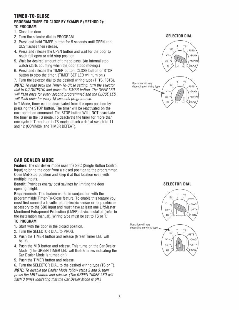
TIMER-TO-CLOSEPROGRAM TIMER-TO-CLOSE BY EXAMPLE (METHOD 2):TO PROGRAM:1. Close the door.2. Turn the selector dial to PROGRAM.3. Press and hold TIMER button for 5 seconds until OPEN and
OLS flashes then release.4. Press and release the OPEN button and wait for the door to
reach full open or mid stop position.5. Wait for desired amount of time to pass. (An internal stop
watch starts counting when the door stops moving.)6. Press and release the TIMER button, CLOSE button or STOP
button to stop the timer. (TIMER SET LED will turn on.)7. Turn the selector dial to the desired wiring type (T, TS, FSTS).NOTE: To read back the Timer-To-Close setting, turn the selector dial to DIAGNOSTIC and press the TIMER button. The OPEN LED will flash once for every second programmed and the CLOSE LED will flash once for every 15 seconds programmed.In T Mode, timer can be deactivated from the open position by pressing the STOP button. The timer will be reactivated on the next operation command. The STOP button WILL NOT deactivate the timer in the TS mode. To deactivate the timer for more than one cycle in T mode or in TS mode, attach a defeat switch to 11 and 12 (COMMON and TIMER DEFEAT).
Operation will vary depending on wiring type
SELECTOR DIAL
CAR DEALER MODEFeature: The car dealer mode uses the SBC (Single Button Control input) to bring the door from a closed position to the programmed Open Mid-Stop position and keep it at that location even with multiple inputs.Benefit: Provides energy cost savings by limiting the door opening height.Requirements: This feature works in conjunction with the programmable Timer-To-Close feature. To enable this feature you must first connect a treadle, photoelectric sensor or loop detector accessory to the SBC input and must have at least one LiftMaster Monitored Entrapment Protection (LMEP) device installed (refer to the installation manual). Wiring type must be set to TS or T.TO PROGRAM:1. Start with the door in the closed position.2. Turn the SELECTOR DIAL to PROG.3. Push the TIMER button and release (Green Timer LED will
be lit).4. Push the MID button and release. This turns on the Car Dealer
Mode. (The GREEN TIMER LED will flash 6 times indicating the Car Dealer Mode is turned on.)
5. Push the TIMER button and release.6. Turn the SELECTOR DIAL to the desired wiring type (TS or T).NOTE: To disable the Dealer Mode follow steps 2 and 3, then press the MRT button and release. (The GREEN TIMER LED will flash 3 times indicating that the Car Dealer Mode is off.)
Operation will vary depending on wiring type
SELECTOR DIAL
9
OPTN
PROG
DIAG
FSTS
TSTE2
D1
C2
B2
OPTN
PROG
DIAG
FSTS
TSTE2
D1
C2
B2
OPTN
PROG
DIAG
FSTS
TSTE2
D1
C2
B2
OPTN
PROG
DIAG
FSTS
TSTE2
D1
C2
B2
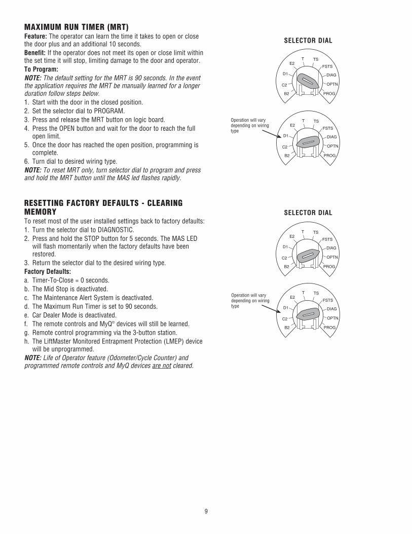
MAXIMUM RUN TIMER (MRT)Feature: The operator can learn the time it takes to open or close the door plus and an additional 10 seconds.Benefit: If the operator does not meet its open or close limit within the set time it will stop, limiting damage to the door and operator.To Program:NOTE: The default setting for the MRT is 90 seconds. In the event the application requires the MRT be manually learned for a longer duration follow steps below.1. Start with the door in the closed position.2. Set the selector dial to PROGRAM.3. Press and release the MRT button on logic board.4. Press the OPEN button and wait for the door to reach the full
open limit.5. Once the door has reached the open position, programming is
complete.6. Turn dial to desired wiring type.NOTE: To reset MRT only, turn selector dial to program and press and hold the MRT button until the MAS led flashes rapidly.
Operation will vary depending on wiring type
SELECTOR DIAL
RESETTING FACTORY DEFAULTS - CLEARING MEMORYTo reset most of the user installed settings back to factory defaults:1. Turn the selector dial to DIAGNOSTIC.2. Press and hold the STOP button for 5 seconds. The MAS LED
will flash momentarily when the factory defaults have been restored.
3. Return the selector dial to the desired wiring type.Factory Defaults:a. Timer-To-Close = 0 seconds.b. The Mid Stop is deactivated.c. The Maintenance Alert System is deactivated.d. The Maximum Run Timer is set to 90 seconds.e. Car Dealer Mode is deactivated.f. The remote controls and MyQ® devices will still be learned.g. Remote control programming via the 3-button station.h. The LiftMaster Monitored Entrapment Protection (LMEP) device
will be unprogrammed.NOTE: Life of Operator feature (Odometer/Cycle Counter) and programmed remote controls and MyQ devices are not cleared.
Operation will vary depending on wiring type
SELECTOR DIAL
10
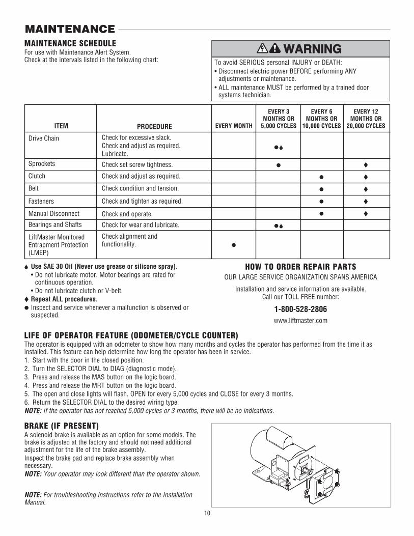
MAINTENANCEMAINTENANCE SCHEDULEFor use with Maintenance Alert System.Check at the intervals listed in the following chart:
HOW TO ORDER REPAIR PARTSOUR LARGE SERVICE ORGANIZATION SPANS AMERICA
Installation and service information are available.Call our TOLL FREE number:
1-800-528-2806www.liftmaster.com
Use SAE 30 Oil (Never use grease or silicone spray). • Do not lubricate motor. Motor bearings are rated for
continuous operation. • Do not lubricate clutch or V-belt. Repeat ALL procedures. Inspect and service whenever a malfunction is observed or
suspected.
To avoid SERIOUS personal INJURY or DEATH:• Disconnect electric power BEFORE performing ANY
adjustments or maintenance.• ALL maintenance MUST be performed by a trained door
systems technician.
ATTENTION
AVERTISSEMENT AVERTISSEMENT
AVERTISSEMENT
WARNING
CAUTION
WARNING
WARNING WARNING
PRECAUCIÓN ADVERTENCIA
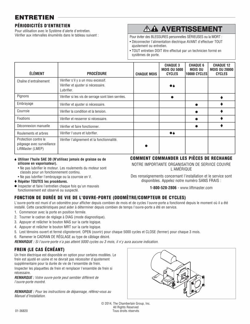
ADVERTENCIA ADVERTENCIA LIFE OF OPERATOR FEATURE (ODOMETER/CYCLE COUNTER)The operator is equipped with an odometer to show how many months and cycles the operator has performed from the time it as installed. This feature can help determine how long the operator has been in service.1. Start with the door in the closed position.2. Turn the SELECTOR DIAL to DIAG (diagnostic mode).3. Press and release the MAS button on the logic board.4. Press and release the MRT button on the logic board.5. The open and close lights will flash. OPEN for every 5,000 cycles and CLOSE for every 3 months.6. Return the SELECTOR DIAL to the desired wiring type.NOTE: If the operator has not reached 5,000 cycles or 3 months, there will be no indications.
EVERY 3 MONTHS OR
5,000 CYCLESEVERY MONTH
EVERY 6 MONTHS OR
10,000 CYCLES
EVERY 12 MONTHS OR
20,000 CYCLESITEM
Drive Chain
Sprockets
Clutch
Belt
Fasteners
Manual Disconnect
Bearings and Shafts
LiftMaster Monitored Entrapment Protection (LMEP)
PROCEDURE
Check for excessive slack. Check and adjust as required.Lubricate.
Check set screw tightness.
Check and adjust as required.
Check condition and tension.
Check and tighten as required.
Check and operate.
Check for wear and lubricate.
Check alignment and functionality.
BRAKE (IF PRESENT)A solenoid brake is available as an option for some models. The brake is adjusted at the factory and should not need additional adjustment for the life of the brake assembly.Inspect the brake pad and replace brake assembly when necessary.NOTE: Your operator may look different than the operator shown.
NOTE: For troubleshooting instructions refer to the Installation Manual.
EXIGENCES D'APPLICATION : Disponible pour tous les actionneurs de porte commerciaux utilisant le tableau de contrôle Logic 5.
NÉCESSAIRE DE REMPLACEMENT DE
TABLEAU DE CONTRÔLE (L5)K001D8075-1
INSTALLATION
Pour éviter des BLESSURES personnelles SÉRIEUSES ou la MORT par électrocution, DÉCONNECTER l’alimentation électrique à l’actionneur AVANT de procéder.
ATTENTION
AVERTISSEMENT AVERTISSEMENT
AVERTISSEMENT AVERTISSEMENT
WARNING
CAUTION
WARNING
WARNING
PRECAUCIÓN ADVERTENCIA
ADVERTENCIA ADVERTENCIA
RETRAIT DU TABLEAU EXISTANT1. Déconnecter l’alimentation à l’actionneur.2. Enlever tous les fils du tableau existant : • Bornier de câblage de commande • Connecteur de câblage du système (J3)REMARQUE : Se souvenir de toutes les connexions de câblage lors de la réinstallation.3. Retirer le câble coaxial du connecteur F du tableau.4. Retirer du tableau toutes les cartes d’option installées de leurs fentes
correspondantes sur le tableau. 5. Retirer le tableau de ses montants.
PARAMÈTRES D’ALIMENTATION ET DE CONNEXION DE CÂBLAGEAvant de faire correspondre tout paramètre de connexion, s’assurer que la tension d’alimentation, la phase du courant, la fréquence et l’intensité sont bien compatibles avec votre actionneur.1. Retirer le nouveau tableau de son sac de protection.2. Faire correspondre les paramètres du tableau existant au nouveau
tableau : • Liaison monophasée et triphasée
Pour les actionneurs triphasés uniquement : NE PAS déplacer la liaison triphasée avant d’avoir terminé l’installation et les instructions particulières qui suivent l’étape 6.
• Liaison de direction du moteur • Cadran de réglageREMARQUE : L’information suivante est stockée dans le micrologiciel et devra être reprogrammée si celui-ci est mis à niveau avec le tableau :• Toutes les télécommandes (sur le récepteur du tableau uniquement)• Temporisation de fermeture• Temporisation maximale de course• Système d’alerte d’entretien• Mi-ouverture et mi-fermeture• Temporisation de préavertissement lorsque la carte d’option TLSCARD
est utilisée• Frein dynamique pour les modèles N4/N4X uniquement lorsqu’une
carte auxiliaire (AUXCARD) est utilisée.
INSTALLATION DU NOUVEAU TABLEAU1. Placer le nouveau tableau dans l’actionneur. Positionner le tableau sur
ses montants en exerçant une pression ferme de manière à ce qu’ils s’insèrent complètement dans les trous de montage.
2. Reconnecter le câble coaxial au connecteur F du tableau.3. Reconnecter tous les fils au bornier du câblage de commande du
tableau de contrôle principal.4. Installer toutes les cartes d’option dans les fentes du tableau de
contrôle.5. S’assurer que le boîtier de branchement est libre de tout débris et outil.6. Reconnecter l’alimentation électrique à l’actionneur et en vérifier le
fonctionnement.
ACTIONNEURS TRIPHASÉS UNIQUEMENT REMARQUE : NE PAS activer l’actionneur avant d’avoir réalisé les
étapes suivantes : 1. Tourner le CADRAN DE RÉGLAGE sur PROG (programmation). 2. Déplacer la liaison de PHASE de la position monophasée à la
position triphasée. 3. Ramener le CADRAN DE RÉGLAGE sur le mode de fonctionnement
désiré.Se reporter aux pages 3 à 10 pour la programmation et les réglages au besoin.
UNE PROGRAMMATION SPÉCIALE EST NÉCESSAIRE POUR LES MODÈLES N4/NX UTILISANT UNE CARTE AUXILIAIRE (AUXCARD). CECI RÈGLE LE FREIN DYNAMIQUE DU MOTEUR. SUIVRE CES INSTRUCTIONS AVANT DE FAIRE FONCTIONNER L’ACTIONNEUR.1. Tourner le CADRAN DE RÉGLAGE sur OPTN.2. Enfoncer et relâcher le bouton MAS.3. Enfoncer et relâcher le bouton MID. La DEL MAS clignotera six
fois.4. Ramener le CADRAN DE RÉGLAGE sur le type de câblage désiré.
2
SLO
T 1
RADIO
SLS
MRT MID TTC
DATA
24VAC
24VAC
LMEP:
EDGE:
OPEN
CLOSE
STOP
COMMON
RELAY A
RELAY B
SBC 1
2
3
4
5
6
7
8
9
10
11
12
13
14
MAS
COMMON
TIMERDEFEAT
POWER
TIMERENABLE
1 2 3
FSTS
DIAG
OPTN
PROG
T TSE2
D1
C2
B2
CLS
OLS
MID
RE
V
ST
D
SLO
T 2
MO
TO
RD
IRE
CT
ION
3-PH
AS
E
1-PH
AS
E
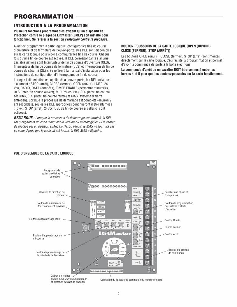
INTRODUCTION À LA PROGRAMMATION
Cadran de réglage(utilisé pour la programmation et la sélection du type de câblage)
Connexion du faisceau de commande du moteur principal
Bouton de la minuterie de fonctionnement maximal
Réceptacles de cartes auxiliaires
en option
Bouton d'apprentissage de mi-course
Bouton d'apprentissage de la minuterie de fermeture
Bouton d'apprentissage radio Bouton Ouvrir
Bouton Fermer
Bouton Arrêt
Bornier du câblage de commande
Cavalier de direction du moteur
Bouton de programmation du système d'alerte d'entretien
Cavalier une phase et trois phases
PROGRAMMATION
VUE D'ENSEMBLE DE LA CARTE LOGIQUE
BOUTON-POUSSOIRS DE LA CARTE LOGIQUE (OPEN (OUVRIR), CLOSE (FERMER), STOP (ARRÊT))
Les boutons OPEN (ouvrir), CLOSE (fermer), STOP (arrêt) sont montés directement sur la carte logique. Ceci facilite la programmation et permet d'avoir la commande de porte à la boîte électrique. La commande d'arrêt ou un cavalier DOIT être connecté entre les bornes 4 et 5 pour que les boutons-poussoirs sur la carte fonctionnent.
Avant de programmer la carte logique, configurer les fins de course d'ouverture et de fermeture de l'ouvre-porte. Des DEL sont disponibles sur la carte logique pour aider à configurer les fins de course. Chaque fois qu'une fin de course est activée, la DEL correspondante s'allume. Les abréviations sont Interrupteur de fin de course d'ouverture (OLS), Interrupteur de fin de course de fermeture (CLS) et Interrupteur de fin de course de sécurité (SLS). Se référer à la manual d'installation pour les instructions de configuration d'interrupteurs de fin de course.Lorsque l'alimentation est appliquée à l'ouvre-porte, les DEL suivantes s'allument : STOP (arrêt), CLOSE (fermer), OPEN (ouvrir), LMEP, 24 Vca, RADIO, DATA (données), TIMER ENABLE (permettre minuterie), OLS (inter. fi n course ouvert), MID (mi-course), SLS (inter. fi n course sécurité), CLS (inter. fi n course fermé) et MAS (système d'alerte entretien). Lorsque le processus de démarrage est complété (environ 2 à 3 secondes), seules les DEL appropriées continueront d'être allumées : (p.ex., STOP (arrêt), 24Vcc, DEL de fi n de course si celles-ci sont activées).
REMARQUE : Lorsque le processus de démarrage est terminé, la DEL MAS clignotera un code indiquant la version du micrologiciel. Si le cadran de réglage est en position DIAG, OPTN, ou PROG, le MAS ne fournira pas ce code. Après que le code ait été fourni, la DEL MAS s'éteindra.
Plusieurs fonctions programmables exigent qu'un dispositif de Protection contre le piégeage LiftMaster (LMEP) soit installé pour fonctionner. Se référer à la section Protection contre le piégeage.
3
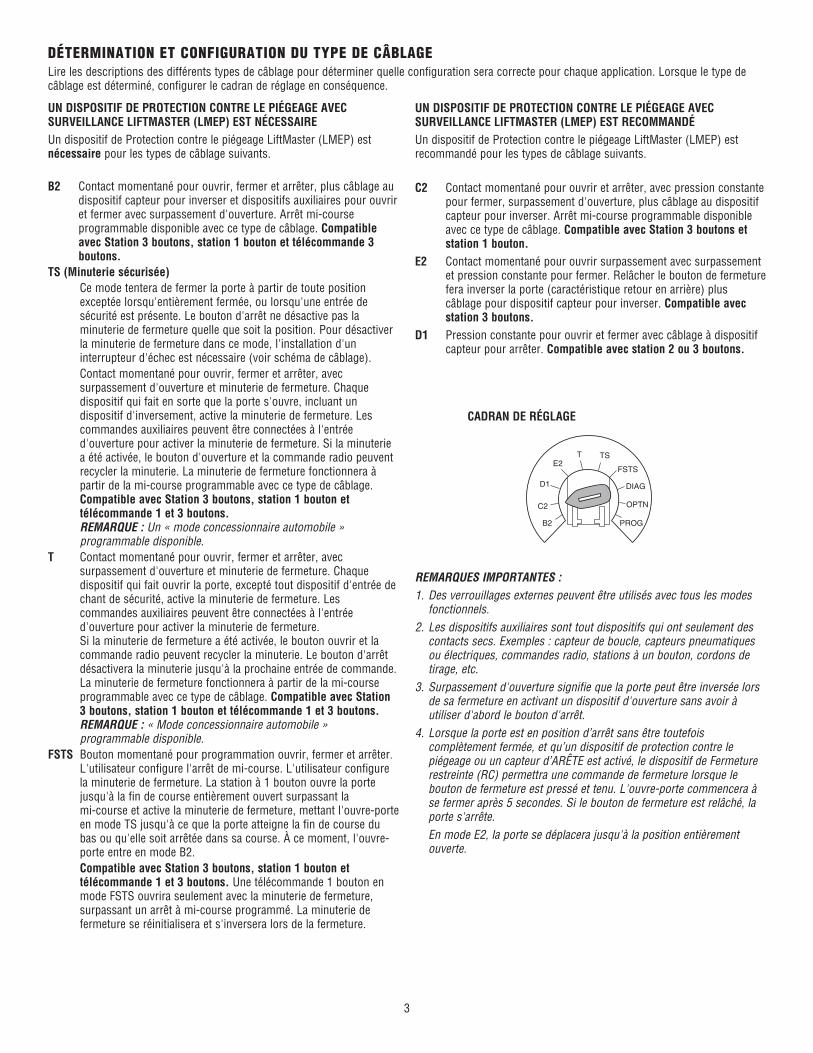
DÉTERMINATION ET CONFIGURATION DU TYPE DE CÂBLAGELire les descriptions des différents types de câblage pour déterminer quelle configuration sera correcte pour chaque application. Lorsque le type de câblage est déterminé, configurer le cadran de réglage en conséquence.
CADRAN DE RÉGLAGE
REMARQUES IMPORTANTES :1. Des verrouillages externes peuvent être utilisés avec tous les modes
fonctionnels.2. Les dispositifs auxiliaires sont tout dispositifs qui ont seulement des
contacts secs. Exemples : capteur de boucle, capteurs pneumatiques ou électriques, commandes radio, stations à un bouton, cordons de tirage, etc.
3. Surpassement d'ouverture signifie que la porte peut être inversée lors de sa fermeture en activant un dispositif d'ouverture sans avoir à utiliser d'abord le bouton d'arrêt.
4. Lorsque la porte est en position d’arrêt sans être toutefois complètement fermée, et qu’un dispositif de protection contre le piégeage ou un capteur d’ARÊTE est activé, le dispositif de Fermeture restreinte (RC) permettra une commande de fermeture lorsque le bouton de fermeture est pressé et tenu. L'ouvre-porte commencera à se fermer après 5 secondes. Si le bouton de fermeture est relâché, la porte s'arrête.
En mode E2, la porte se déplacera jusqu'à la position entièrement ouverte.
UN DISPOSITIF DE PROTECTION CONTRE LE PIÉGEAGE AVEC SURVEILLANCE LIFTMASTER (LMEP) EST NÉCESSAIREUn dispositif de Protection contre le piégeage LiftMaster (LMEP) est nécessaire pour les types de câblage suivants.
UN DISPOSITIF DE PROTECTION CONTRE LE PIÉGEAGE AVEC SURVEILLANCE LIFTMASTER (LMEP) EST RECOMMANDÉUn dispositif de Protection contre le piégeage LiftMaster (LMEP) est recommandé pour les types de câblage suivants.
B2 Contact momentané pour ouvrir, fermer et arrêter, plus câblage au dispositif capteur pour inverser et dispositifs auxiliaires pour ouvrir et fermer avec surpassement d'ouverture. Arrêt mi-course programmable disponible avec ce type de câblage. Compatible avec Station 3 boutons, station 1 bouton et télécommande 3 boutons.
TS (Minuterie sécurisée) Ce mode tentera de fermer la porte à partir de toute position
exceptée lorsqu'entièrement fermée, ou lorsqu'une entrée de sécurité est présente. Le bouton d'arrêt ne désactive pas la minuterie de fermeture quelle que soit la position. Pour désactiver la minuterie de fermeture dans ce mode, l'installation d'un interrupteur d'échec est nécessaire (voir schéma de câblage).
Contact momentané pour ouvrir, fermer et arrêter, avec surpassement d'ouverture et minuterie de fermeture. Chaque dispositif qui fait en sorte que la porte s'ouvre, incluant un dispositif d'inversement, active la minuterie de fermeture. Les commandes auxiliaires peuvent être connectées à l'entrée d'ouverture pour activer la minuterie de fermeture. Si la minuterie a été activée, le bouton d'ouverture et la commande radio peuvent recycler la minuterie. La minuterie de fermeture fonctionnera à partir de la mi-course programmable avec ce type de câblage. Compatible avec Station 3 boutons, station 1 bouton et télécommande 1 et 3 boutons.REMARQUE : Un « mode concessionnaire automobile » programmable disponible.
T Contact momentané pour ouvrir, fermer et arrêter, avec surpassement d'ouverture et minuterie de fermeture. Chaque dispositif qui fait ouvrir la porte, excepté tout dispositif d'entrée de chant de sécurité, active la minuterie de fermeture. Les commandes auxiliaires peuvent être connectées à l'entrée d'ouverture pour activer la minuterie de fermeture. Si la minuterie de fermeture a été activée, le bouton ouvrir et la commande radio peuvent recycler la minuterie. Le bouton d'arrêt désactivera la minuterie jusqu'à la prochaine entrée de commande. La minuterie de fermeture fonctionnera à partir de la mi-course programmable avec ce type de câblage. Compatible avec Station 3 boutons, station 1 bouton et télécommande 1 et 3 boutons. REMARQUE : « Mode concessionnaire automobile » programmable disponible.
FSTS Bouton momentané pour programmation ouvrir, fermer et arrêter. L'utilisateur configure l'arrêt de mi-course. L'utilisateur configure la minuterie de fermeture. La station à 1 bouton ouvre la porte jusqu'à la fin de course entièrement ouvert surpassant la mi-course et active la minuterie de fermeture, mettant l'ouvre-porte en mode TS jusqu'à ce que la porte atteigne la fin de course du bas ou qu'elle soit arrêtée dans sa course. À ce moment, l'ouvre-porte entre en mode B2.
Compatible avec Station 3 boutons, station 1 bouton et télécommande 1 et 3 boutons. Une télécommande 1 bouton en mode FSTS ouvrira seulement avec la minuterie de fermeture, surpassant un arrêt à mi-course programmé. La minuterie de fermeture se réinitialisera et s'inversera lors de la fermeture.
C2 Contact momentané pour ouvrir et arrêter, avec pression constante pour fermer, surpassement d'ouverture, plus câblage au dispositif capteur pour inverser. Arrêt mi-course programmable disponible avec ce type de câblage. Compatible avec Station 3 boutons et station 1 bouton.
E2 Contact momentané pour ouvrir surpassement avec surpassement et pression constante pour fermer. Relâcher le bouton de fermeture fera inverser la porte (caractéristique retour en arrière) plus câblage pour dispositif capteur pour inverser. Compatible avec station 3 boutons.
D1 Pression constante pour ouvrir et fermer avec câblage à dispositif capteur pour arrêter. Compatible avec station 2 ou 3 boutons.
OPTN
PROG
DIAG
FSTS
TSTE2
D1
C2
B2
4
TÉLÉCOMMANDE À UN BOUTON PROGRAMMÉE COMME UNE COMMANDE À UN BOUTON (SBC)Cette fonction programme une télécommande comme commande à un bouton sans fil. Cette fonction fonctionne dans les modes suivants : En mode B2, le fonctionnement est OUVRIR/ARRÊTER/FERMER/
INVERSER/ARRÊTER. En modes T et TS, le fonctionnement est OUVRIR/ARRÊTER/
FERMER/INVERSER/ARRÊTER ET minuterie de fermeture démarrer/rafraîchir. REMARQUE : Si le mode concessionnaire automobile est activé, SBS sera ouvert seulement lors d'un arrêt à l'ouverture mi-course.
En mode FSTS, le fonctionnement est OUVERT avec minuterie de fermeture démarrer/rafraîchie seulement, surpassant un Ouvrir à mi-course programmé.
1. Appuyer et relâcher le bouton RADIO sur la carte logique(la DEL RADIO s'allume).
2. Pressez et relâchez le bouton SBC branché à l’extérieur ou le bouton TTC de la carte logique (le bouton DEL RADIO clignotera rapidement, puis se stabilisera).
3. Appuyer et tenir le bouton de la télécommande jusqu'à ce que la DEL RADIO clignote rapidement. La DEL RADIO demeurera allumée lorsque le bouton sera relâché.
4. Appuyer et lâcher le bouton RADIO sur la carte logique (la DEL RADIO clignote rapidement puis s'éteint). Le mode de programmation est quitté si aucune activité n'est effectuée durant 30 secondes. Les boutons DEL MAS et RADIO clignoteront brièvement pour indiquer que le mode de programmation de la carte RADIO est désactivé pour les télécommandes et les dispositifs d’entrée sans clé. La carte RADIO demeurera en mode de programmation pour 150 secondes supplémentaires afin d’accommoder les dispositifs
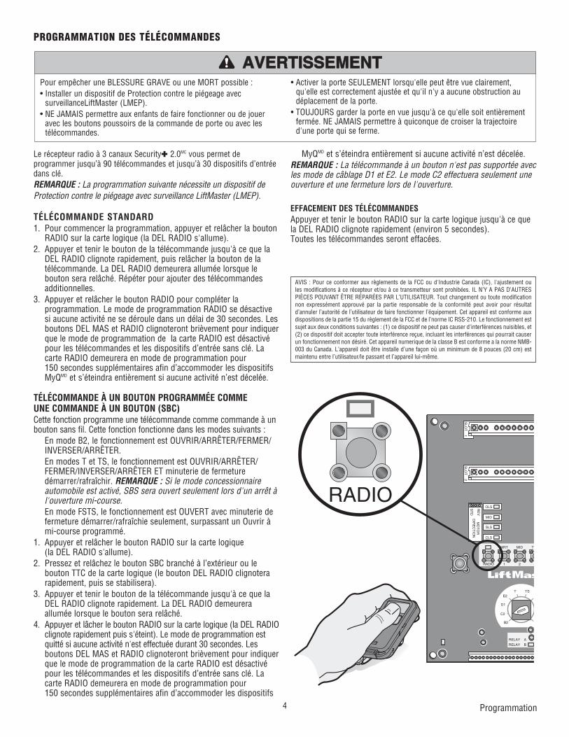
Le récepteur radio à 3 canaux Security✚ 2.0MC vous permet de programmer jusqu’à 90 télécommandes et jusqu’à 30 dispositifs d’entrée dans clé.REMARQUE : La programmation suivante nécessite un dispositif de Protection contre le piégeage avec surveillance LiftMaster (LMEP).
TÉLÉCOMMANDE STANDARD1. Pour commencer la programmation, appuyer et relâcher la bouton
RADIO sur la carte logique (la DEL RADIO s'allume).2. Appuyer et tenir le bouton de la télécommande jusqu'à ce que la
DEL RADIO clignote rapidement, puis relâcher la bouton de la télécommande. La DEL RADIO demeurera allumée lorsque le bouton sera relâché. Répéter pour ajouter des télécommandes additionnelles.
3. Appuyer et relâcher le bouton RADIO pour compléter la programmation. Le mode de programmation RADIO se désactive si aucune activité ne se déroule dans un délai de 30 secondes. Les boutons DEL MAS et RADIO clignoteront brièvement pour indiquer que le mode de programmation de la carte RADIO est désactivé pour les télécommandes et les dispositifs d’entrée sans clé. La carte RADIO demeurera en mode de programmation pour 150 secondes supplémentaires afin d’accommoder les dispositifs MyQMD et s’éteindra entièrement si aucune activité n’est décelée.
PROGRAMMATION DES TÉLÉCOMMANDES
Programmation
Pour empêcher une BLESSURE GRAVE ou une MORT possible :• Installer un dispositif de Protection contre le piégeage avec
surveillanceLiftMaster (LMEP).• NE JAMAIS permettre aux enfants de faire fonctionner ou de jouer
avec les boutons poussoirs de la commande de porte ou avec les télécommandes.
• Activer la porte SEULEMENT lorsqu'elle peut être vue clairement, qu'elle est correctement ajustée et qu'il n'y a aucune obstruction au déplacement de la porte.
• TOUJOURS garder la porte en vue jusqu'à ce qu'elle soit entièrement fermée. NE JAMAIS permettre à quiconque de croiser la trajectoire d'une porte qui se ferme.
ATTENTION
AVERTISSEMENT AVERTISSEMENT AVERTISSEMENT
AVERTISSEMENT
WARNING
CAUTION
WARNING
WARNING
PRECAUCIÓN ADVERTENCIA
ADVERTENCIA ADVERTENCIA
MyQMD et s’éteindra entièrement si aucune activité n’est décelée.REMARQUE : La télécommande à un bouton n'est pas supportée avec les mode de câblage D1 et E2. Le mode C2 effectuera seulement une ouverture et une fermeture lors de l'ouverture.
EFFACEMENT DES TÉLÉCOMMANDESAppuyer et tenir le bouton RADIO sur la carte logique jusqu'à ce que la DEL RADIO clignote rapidement (environ 5 secondes).Toutes les télécommandes seront effacées.
SLO
T 1
RADIO
SLS
MRT MID TT
RELAY A
RELAY B
1 2 3
F
P
T TSE2
D1
C2
B2
CLS
OLS
MID
RE
V
ST
D
SLO
T 2
MO
TO
RD
IRE
CT
ION
RADIO
AVIS : Pour ce conformer aux règlements de la FCC ou d'Industrie Canada (IC), l'ajustement ou les modifications à ce récepteur et/ou à ce transmetteur sont prohibées. IL N’Y A PAS D’AUTRES PIÈCES POUVANT ÊTRE RÉPARÉES PAR L’UTILISATEUR. Tout changement ou toute modification non expressément approuvé par la partie responsable de la conformité peut avoir pour résultat d’annuler l’autorité de l’utilisateur de faire fonctionner l’équipement. Cet appareil est conforme aux dispositions de la partie 15 du règlement de la FCC et de l’norme IC RSS-210. Le fonctionnement est sujet aux deux conditions suivantes : (1) ce dispositif ne peut pas causer d’interférences nuisibles, et (2) ce dispositif doit accepter toute interférence reçue, incluant les interférences qui pourrait causer un fonctionnement non désiré. Cet appareil numerique de la classe B est conforme a la norme NMB-003 du Canada. L’appareil doit être installe d’une façon où un minimum de 8 pouces (20 cm) est maintenu entre l’utilisateur/le passant et l’appareil lui-même.
5
SLO
T 1
RADIO
SLS
MRT MID TTC
DATA
24VAC
24VAC
LMEP:
EDGE:
OPEN
CLOSE
STOP
COMMON
RELAY A
RELAY B
SBC 1
2
3
4
5
6
7
8
9
10
11
12
13
14
MAS
COMMON
TIMERDEFEAT
POWER
TIMERENABLE
1 2 3
FSTS
DIAG
OPTN
PROG
T TSE2
D1
C2
B2
CLS
OLS
MID
RE
V
ST
D
SLO
T 2
MO
TO
RD
IRE
CT
ION
3-PH
AS
E
1-PH
AS
E
EDGE:
OPEN
CLOSE
STOP
COMMON
MERNABLE
OPEN
CLOSE
STOP
REMARQUE : La programmation suivante nécessite un dispositif de Protection contre le piégeage avec surveillance LiftMaster (LMEP).Votre télécommande Security✚ 2.0MC ou DIP programmable peut être programmée pour fonctionner comme station de commande sans fil à 3 boutons : le gros bouton ouvrira la porte, le bouton du milieu fermera la porte et le troisième bouton arrêtera le mouvement de la porte. Vous pouvez configurer cette fonctionnalité de la façon suivante :1. Pour commencer la programmation, appuyer et relâcher la bouton
RADIO sur la carte logique (la DEL RADIO s'allume).2. Pour programmer le bouton OPEN (ouvrir) à une télécommande,
appuyer et relâcher le bouton OPEN (ouvrir) sur la carte logique. La DEL RADIO clignote puis demeure allumée. Ensuite appuyer sur le bouton correspondant de la télécommande. La DEL RADIO sur la carte logique clignote, ceci confirme qu ela télécommande a été programmée. (En programmant la télécommande vous utilisez 1 canal des 90 canaux sur le récepteur radio.)
3. Pour programmer le bouton CLOSE (fermer) à une télécommande, appuyer et relâcher le bouton CLOSE (fermer) sur la carte logique. La DEL RADIO clignote puis demeure allumée. Ensuite appuyer sur le bouton correspondant de la télécommande. La DEL RADIO sur la carte logique clignote, ceci confirme qu ela télécommande a été programmée. (En programmant la télécommande vous utilisez 1 canal des 90 canaux sur le récepteur radio.)
4. Pour programmer le bouton STOP (arrêt) à une télécommande, appuyer et relâcher le bouton STOP (arrêt) sur la carte logique. La DEL RADIO clignote puis demeure allumée. Ensuite appuyer sur le bouton correspondant de la télécommande. La DEL RADIO sur la carte logique clignote, ceci confirme qu ela télécommande a été programmée. (En programmant la télécommande vous utilisez 1 canal des 90 canaux sur le récepteur radio.)
5. Après l'apprentissage des télécommande appuyer sur le bouton RADIO sur la carte logique (la DEL RADIO s'éteint). REMARQUE : Si aucune activité n’est décelée dans un délai de 30 secondes, es boutons DEL MAS et RADIO clignoteront brièvement pour indiquer que le mode de programmation de la carte RADIO est désactivé pour les télécommandes et les dispositifs d’entrée sans clé. La RADIO demeurera en mode de programmation pour 150 secondes supplémentaires pour les dispositifs MyQMD et se s’éteindra entièrement sans activité.
Open (Ouvrir)
Close (Fermer)
Stop (Arrêt)
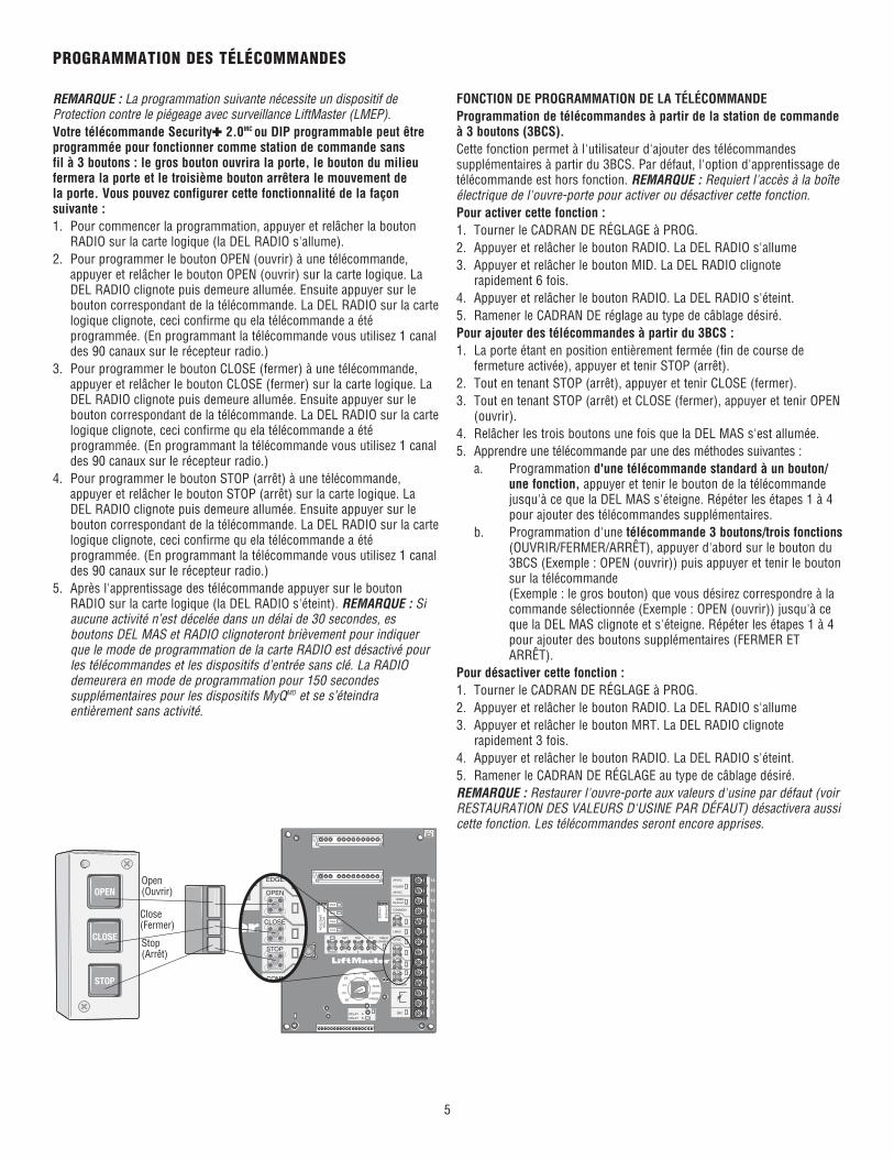
FONCTION DE PROGRAMMATION DE LA TÉLÉCOMMANDEProgrammation de télécommandes à partir de la station de commande à 3 boutons (3BCS).Cette fonction permet à l'utilisateur d'ajouter des télécommandes supplémentaires à partir du 3BCS. Par défaut, l'option d'apprentissage de télécommande est hors fonction. REMARQUE : Requiert l'accès à la boîte électrique de l'ouvre-porte pour activer ou désactiver cette fonction.Pour activer cette fonction :1. Tourner le CADRAN DE RÉGLAGE à PROG.2. Appuyer et relâcher le bouton RADIO. La DEL RADIO s'allume3. Appuyer et relâcher le bouton MID. La DEL RADIO clignote
rapidement 6 fois.4. Appuyer et relâcher le bouton RADIO. La DEL RADIO s'éteint.5. Ramener le CADRAN DE réglage au type de câblage désiré.Pour ajouter des télécommandes à partir du 3BCS :1. La porte étant en position entièrement fermée (fin de course de
fermeture activée), appuyer et tenir STOP (arrêt).2. Tout en tenant STOP (arrêt), appuyer et tenir CLOSE (fermer).3. Tout en tenant STOP (arrêt) et CLOSE (fermer), appuyer et tenir OPEN
(ouvrir).4. Relâcher les trois boutons une fois que la DEL MAS s'est allumée.5. Apprendre une télécommande par une des méthodes suivantes : a. Programmation d'une télécommande standard à un bouton/
une fonction, appuyer et tenir le bouton de la télécommande jusqu'à ce que la DEL MAS s'éteigne. Répéter les étapes 1 à 4 pour ajouter des télécommandes supplémentaires.
b. Programmation d'une télécommande 3 boutons/trois fonctions (OUVRIR/FERMER/ARRÊT), appuyer d'abord sur le bouton du 3BCS (Exemple : OPEN (ouvrir)) puis appuyer et tenir le bouton sur la télécommande (Exemple : le gros bouton) que vous désirez correspondre à la commande sélectionnée (Exemple : OPEN (ouvrir)) jusqu'à ce que la DEL MAS clignote et s'éteigne. Répéter les étapes 1 à 4 pour ajouter des boutons supplémentaires (FERMER ET ARRÊT).
Pour désactiver cette fonction :1. Tourner le CADRAN DE RÉGLAGE à PROG.2. Appuyer et relâcher le bouton RADIO. La DEL RADIO s'allume3. Appuyer et relâcher le bouton MRT. La DEL RADIO clignote
rapidement 3 fois.4. Appuyer et relâcher le bouton RADIO. La DEL RADIO s'éteint.5. Ramener le CADRAN DE RÉGLAGE au type de câblage désiré.REMARQUE : Restaurer l'ouvre-porte aux valeurs d'usine par défaut (voir RESTAURATION DES VALEURS D'USINE PAR DÉFAUT) désactivera aussi cette fonction. Les télécommandes seront encore apprises.
PROGRAMMATION DES TÉLÉCOMMANDES
6
OPEN (OUVRIR)
CLOSE (FERMER)
STOP (ARRÊT)
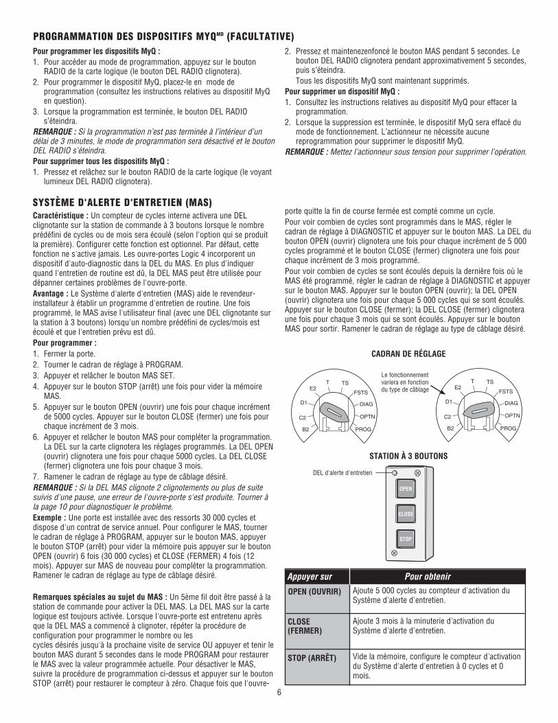
SYSTÈME D'ALERTE D'ENTRETIEN (MAS)Caractéristique : Un compteur de cycles interne activera une DEL clignotante sur la station de commande à 3 boutons lorsque le nombre prédéfini de cycles ou de mois sera écoulé (selon l'option qui se produit la première). Configurer cette fonction est optionnel. Par défaut, cette fonction ne s'active jamais. Les ouvre-portes Logic 4 incorporent un dispositif d'auto-diagnostic dans la DEL du MAS. En plus d'indiquer quand l'entretien de routine est dû, la DEL MAS peut être utilisée pour dépanner certaines problèmes de l'ouvre-porte.Avantage : Le Système d'alerte d'entretien (MAS) aide le revendeur-installateur à établir un programme d'entretien de routine. Une fois programmé, le MAS avise l'utilisateur final (avec une DEL clignotante sur la station à 3 boutons) lorsqu'un nombre prédéfini de cycles/mois est écoulé et que l'entretien prévu est dû.Pour programmer :1. Fermer la porte.2. Tourner le cadran de réglage à PROGRAM.3. Appuyer et relâcher le bouton MAS SET.4. Appuyer sur le bouton STOP (arrêt) une fois pour vider la mémoire
MAS.5. Appuyer sur le bouton OPEN (ouvrir) une fois pour chaque incrément
de 5000 cycles. Appuyer sur le bouton CLOSE (fermer) une fois pour chaque incrément de 3 mois.
6. Appuyer et relâcher le bouton MAS pour compléter la programmation. La DEL sur la carte clignotera les réglages programmés. La DEL OPEN (ouvrir) clignotera une fois pour chaque 5000 cycles. La DEL CLOSE (fermer) clignotera une fois pour chaque 3 mois.
7. Ramener le cadran de réglage au type de câblage désiré.REMARQUE : Si la DEL MAS clignote 2 clignotements ou plus de suite suivis d'une pause, une erreur de l'ouvre-porte s'est produite. Tourner à la page 10 pour diagnostiquer le problème.Exemple : Une porte est installée avec des ressorts 30 000 cycles et dispose d'un contrat de service annuel. Pour configurer le MAS, tourner le cadran de réglage à PROGRAM, appuyer sur le bouton MAS, appuyer le bouton STOP (arrêt) pour vider la mémoire puis appuyer sur le bouton OPEN (ouvrir) 6 fois (30 000 cycles) et CLOSE (FERMER) 4 fois (12 mois). Appuyer sur MAS de nouveau pour compléter la programmation. Ramener le cadran de réglage au type de câblage désiré.
Remarques spéciales au sujet du MAS : Un 5ème fil doit être passé à la station de commande pour activer la DEL MAS. La DEL MAS sur la carte logique est toujours activée. Lorsque l'ouvre-porte est entretenu après que la DEL MAS a commencé à clignoter, répéter la procédure de configuration pour programmer le nombre ou les cycles désirés jusqu'à la prochaine visite de service OU appuyer et tenir le bouton MAS durant 5 secondes dans le mode PROGRAM pour restaurer le MAS avec la valeur programmée actuelle. Pour désactiver le MAS, suivre la procédure de programmation ci-dessus et appuyer sur le bouton STOP (arrêt) pour restaurer le compteur à zéro. Chaque fois que l'ouvre-
Ajoute 5 000 cycles au compteur d'activation du Système d'alerte d'entretien.
Ajoute 3 mois à la minuterie d'activation du Système d'alerte d'entretien.
Vide la mémoire, configure le compteur d'activation du Système d'alerte d'entretien à 0 cycles et 0 mois.
Appuyer sur Pour obtenir
CADRAN DE RÉGLAGE
STATION À 3 BOUTONS
DEL d'alerte d'entretien
OPTN
PROG
DIAG
FSTS
TSTE2
D1
C2
B2
OPEN
CLOSE
STOP
OPTN
PROG
DIAG
FSTS
TSTE2
D1
C2
B2
Le fonctionnement variera en fonction du type de câblage
Pour programmer les dispositifs MyQ :1. Pour accéder au mode de programmation, appuyez sur le bouton
RADIO de la carte logique (le bouton DEL RADIO clignotera).2. Pour programmer le dispositif MyQ, placez-le en mode de
programmation (consultez les instructions relatives au dispositif MyQ en question).
3. Lorsque la programmation est terminée, le bouton DEL RADIO s’éteindra.
REMARQUE : Si la programmation n’est pas terminée à l’intérieur d’un délai de 3 minutes, le mode de programmation sera désactivé et le bouton DEL RADIO s’éteindra.Pour supprimer tous les dispositifs MyQ :1. Pressez et relâchez sur le bouton RADIO de la carte logique (le voyant
lumineux DEL RADIO clignotera).
2. Pressez et maintenezenfoncé le bouton MAS pendant 5 secondes. Le bouton DEL RADIO clignotera pendant approximativement 5 secondes, puis s’éteindra.
Tous les dispositifs MyQ sont maintenant supprimés.Pour supprimer un dispositif MyQ :1. Consultez les instructions relatives au dispositif MyQ pour effacer la
programmation.2. Lorsque la suppression est terminée, le dispositif MyQ sera effacé du
mode de fonctionnement. L’actionneur ne nécessite aucune reprogrammation pour supprimer le dispositif MyQ.
REMARQUE : Mettez l’actionneur sous tension pour supprimer l’opération.
PROGRAMMATION DES DISPOSITIFS MYQMD (FACULTATIVE)
porte quitte la fin de course fermée est compté comme un cycle.Pour voir combien de cycles sont programmés dans le MAS, régler le cadran de réglage à DIAGNOSTIC et appuyer sur le bouton MAS. La DEL du bouton OPEN (ouvrir) clignotera une fois pour chaque incrément de 5 000 cycles programmé et le bouton CLOSE (fermer) clignotera une fois pour chaque incrément de 3 mois programmé.Pour voir combien de cycles se sont écoulés depuis la dernière fois où le MAS été programmé, régler le cadran de réglage à DIAGNOSTIC et appuyer sur le bouton MAS. Appuyer sur le bouton OPEN (ouvrir); la DEL OPEN (ouvrir) clignotera une fois pour chaque 5 000 cycles qui se sont écoulés. Appuyer sur le bouton CLOSE (fermer); la DEL CLOSE (fermer) clignotera une fois pour chaque 3 mois qui se sont écoulés. Appuyer sur le bouton MAS pour sortir. Ramener le cadran de réglage au type de câblage désiré.
7
OPTN
PROG
DIAG
FSTS
TSTE2
D1
C2
B2
OPTN
PROG
DIAG
FSTS
TSTE2
D1
C2
B2
OPTN
PROG
DIAG
FSTS
TSTE2
D1
C2
B2
OPTN
PROG
DIAG
FSTS
TSTE2
D1
C2
B2
CADRAN DE RÉGLAGE
Le fonctionnement
variera en fonction du type
de câblage
CADRAN DE RÉGLAGE
Pour empêcher une BLESSURE GRAVE ou une MORT possible :• Installer un dispositif de Protection contre le piégeage avec
surveillance LiftMaster (LMEP).• NE JAMAIS permettre aux enfants de faire fonctionner ou de jouer
avec les boutons poussoirs de la commande de porte ou avec les télécommandes.
• Activer la porte SEULEMENT lorsqu'elle peut être vue clairement, qu'elle est correctement ajustée et qu'il n'y a aucune obstruction au déplacement de la porte.
• TOUJOURS garder la porte en vue jusqu'à ce qu'elle soit entièrement fermée. NE JAMAIS permettre à quelqu'un de se trouver dans la trajectoire de la porte qui se ferme.
ATTENTION
AVERTISSEMENT AVERTISSEMENT AVERTISSEMENT
AVERTISSEMENT
WARNING
CAUTION
WARNING
WARNING
PRECAUCIÓN ADVERTENCIA
ADVERTENCIA ADVERTENCIA
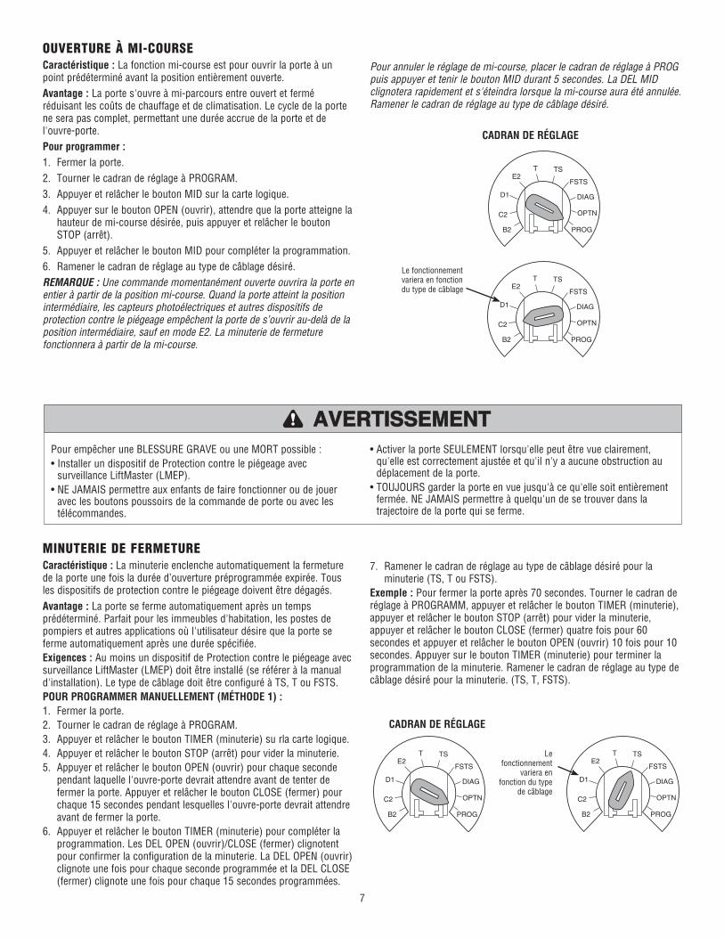
OUVERTURE À MI-COURSECaractéristique : La fonction mi-course est pour ouvrir la porte à un point prédéterminé avant la position entièrement ouverte.Avantage : La porte s'ouvre à mi-parcours entre ouvert et fermé réduisant les coûts de chauffage et de climatisation. Le cycle de la porte ne sera pas complet, permettant une durée accrue de la porte et de l'ouvre-porte.Pour programmer :1. Fermer la porte.2. Tourner le cadran de réglage à PROGRAM.3. Appuyer et relâcher le bouton MID sur la carte logique.4. Appuyer sur le bouton OPEN (ouvrir), attendre que la porte atteigne la
hauteur de mi-course désirée, puis appuyer et relâcher le bouton STOP (arrêt).
5. Appuyer et relâcher le bouton MID pour compléter la programmation.6. Ramener le cadran de réglage au type de câblage désiré.REMARQUE : Une commande momentanément ouverte ouvrira la porte en entier à partir de la position mi-course. Quand la porte atteint la position intermédiaire, les capteurs photoélectriques et autres dispositifs de protection contre le piégeage empêchent la porte de s’ouvrir au-delà de la position intermédiaire, sauf en mode E2. La minuterie de fermeture fonctionnera à partir de la mi-course.
MINUTERIE DE FERMETURECaractéristique : La minuterie enclenche automatiquement la fermeture de la porte une fois la durée d’ouverture préprogrammée expirée. Tous les dispositifs de protection contre le piégeage doivent être dégagés.Avantage : La porte se ferme automatiquement après un temps prédéterminé. Parfait pour les immeubles d'habitation, les postes de pompiers et autres applications où l'utilisateur désire que la porte se ferme automatiquement après une durée spécifiée.Exigences : Au moins un dispositif de Protection contre le piégeage avec surveillance LiftMaster (LMEP) doit être installé (se référer à la manual d'installation). Le type de câblage doit être configuré à TS, T ou FSTS.POUR PROGRAMMER MANUELLEMENT (MÉTHODE 1) :1. Fermer la porte.2. Tourner le cadran de réglage à PROGRAM.3. Appuyer et relâcher le bouton TIMER (minuterie) su rla carte logique.4. Appuyer et relâcher le bouton STOP (arrêt) pour vider la minuterie.5. Appuyer et relâcher le bouton OPEN (ouvrir) pour chaque seconde
pendant laquelle l'ouvre-porte devrait attendre avant de tenter de fermer la porte. Appuyer et relâcher le bouton CLOSE (fermer) pour chaque 15 secondes pendant lesquelles l'ouvre-porte devrait attendre avant de fermer la porte.
6. Appuyer et relâcher le bouton TIMER (minuterie) pour compléter la programmation. Les DEL OPEN (ouvrir)/CLOSE (fermer) clignotent pour confirmer la configuration de la minuterie. La DEL OPEN (ouvrir) clignote une fois pour chaque seconde programmée et la DEL CLOSE (fermer) clignote une fois pour chaque 15 secondes programmées.
Le fonctionnement variera en fonction du type de câblage
7. Ramener le cadran de réglage au type de câblage désiré pour la minuterie (TS, T ou FSTS).
Exemple : Pour fermer la porte après 70 secondes. Tourner le cadran de réglage à PROGRAMM, appuyer et relâcher le bouton TIMER (minuterie), appuyer et relâcher le bouton STOP (arrêt) pour vider la minuterie, appuyer et relâcher le bouton CLOSE (fermer) quatre fois pour 60 secondes et appuyer et relâcher le bouton OPEN (ouvrir) 10 fois pour 10 secondes. Appuyer sur le bouton TIMER (minuterie) pour terminer la programmation de la minuterie. Ramener le cadran de réglage au type de câblage désiré pour la minuterie. (TS, T, FSTS).
Pour annuler le réglage de mi-course, placer le cadran de réglage à PROG puis appuyer et tenir le bouton MID durant 5 secondes. La DEL MID clignotera rapidement et s'éteindra lorsque la mi-course aura été annulée. Ramener le cadran de réglage au type de câblage désiré.
8
OPTN
PROG
DIAG
FSTS
TSTE2
D1
C2
B2
OPTN
PROG
DIAG
FSTS
TSTE2
D1
C2
B2
OPTN
PROG
DIAG
FSTS
TSTE2
D1
C2
B2
OPTN
PROG
DIAG
FSTS
TSTE2
D1
C2
B2
MINUTERIE DE FERMETUREPROGRAMMATION DE LA MINUTERIE DE FERMETURE PAR EXEMPLE (MÉTHODE 2) :POUR PROGRAMMER :1. Fermer la porte.2. Tourner le cadran de réglage à PROGRAM.3. Appuyer et tenir le bouton TIMER (minuterie) durant 5 secondes
jusqu'à ce que OPEN (ouvrir) et OLS clignotent puis relâcher.4. Appuyer et relâcher le bouton OPEN (ouvrir) puis attendre que la porte
atteigne la position entièrement ouverte ou mi-course.5. Attendre que le temps désiré s'écoule. (Un chronomètre interne
commence à compter lorsque la porte cesse de bouger.)6. Appuyer et relâcher le bouton TIMER (minuterie), le bouton CLOSE
(fermer) ou le bouton STOP (arrêt) pour arrêter la minuterie. (la DEL TIMER SET (réglage de minuterie) s'allume.)
7. Ramener le cadran de réglage au type de câblage désiré (T, TS ou FSTS).REMARQUE : Pour relire le réglage de minuterie de fermeture, ramener le cadran de réglage à DIAGNOSTIC et appuyer sur le bouton TIMER (minuterie). La DEL OPEN (ouvrir) clignote une fois pour chaque seconde programmée et la DEL CLOSE (fermer) clignote une fois pour chaque 15 secondes programmées.En mode T, la minuterie peut être désactivée de la position ouverte en appuyant sur le bouton STOP (arrêt). La minuterie sera réactivée lors de la prochaine commande de fonctionnement. Le bouton STOP (arrêt) NE désactivera PAS la minuterie en mode TS. Pour désactiver la minuterie durant plus d'un cycle en mode T ou en mode TS, fixer un interrupteur d'échec à 11 et 12 (COMMON (commun) et TIMER DEFEAT (échec de minuterie)).
Le fonctionnement variera en fonction du type de câblage
CADRAN DE RÉGLAGE
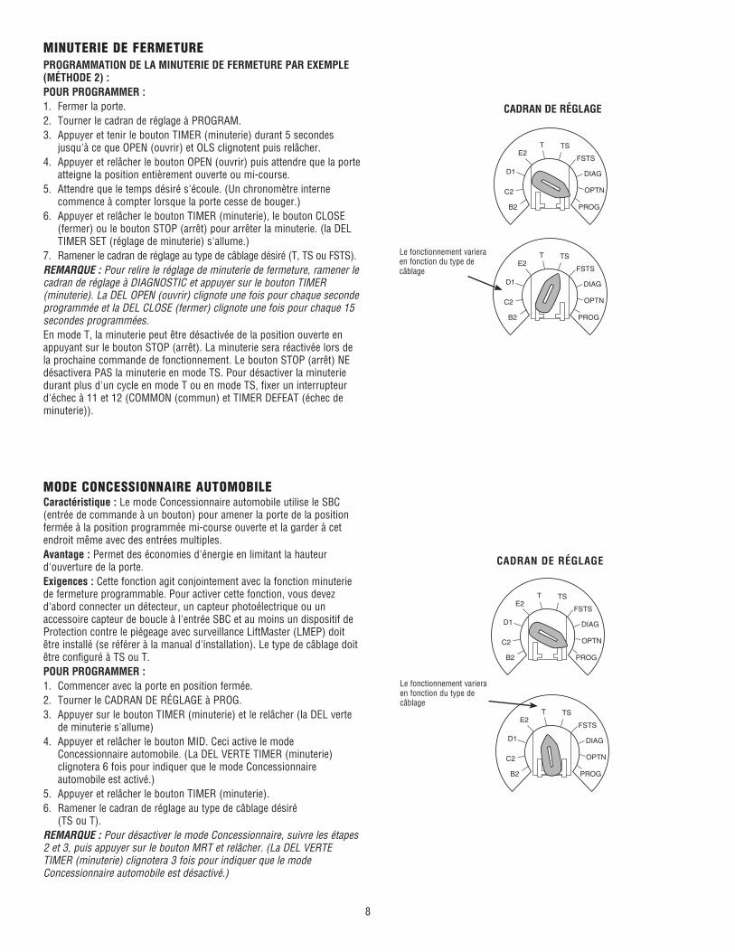
MODE CONCESSIONNAIRE AUTOMOBILECaractéristique : Le mode Concessionnaire automobile utilise le SBC (entrée de commande à un bouton) pour amener la porte de la position fermée à la position programmée mi-course ouverte et la garder à cet endroit même avec des entrées multiples.Avantage : Permet des économies d'énergie en limitant la hauteur d'ouverture de la porte.Exigences : Cette fonction agit conjointement avec la fonction minuterie de fermeture programmable. Pour activer cette fonction, vous devez d'abord connecter un détecteur, un capteur photoélectrique ou un accessoire capteur de boucle à l'entrée SBC et au moins un dispositif de Protection contre le piégeage avec surveillance LiftMaster (LMEP) doit être installé (se référer à la manual d'installation). Le type de câblage doit être configuré à TS ou T.POUR PROGRAMMER :1. Commencer avec la porte en position fermée.2. Tourner le CADRAN DE RÉGLAGE à PROG.3. Appuyer sur le bouton TIMER (minuterie) et le relâcher (la DEL verte
de minuterie s'allume)4. Appuyer et relâcher le bouton MID. Ceci active le mode
Concessionnaire automobile. (La DEL VERTE TIMER (minuterie) clignotera 6 fois pour indiquer que le mode Concessionnaire automobile est activé.)
5. Appuyer et relâcher le bouton TIMER (minuterie).6. Ramener le cadran de réglage au type de câblage désiré
(TS ou T).REMARQUE : Pour désactiver le mode Concessionnaire, suivre les étapes 2 et 3, puis appuyer sur le bouton MRT et relâcher. (La DEL VERTE TIMER (minuterie) clignotera 3 fois pour indiquer que le mode Concessionnaire automobile est désactivé.)
Le fonctionnement variera en fonction du type de câblage
CADRAN DE RÉGLAGE
9
OPTN
PROG
DIAG
FSTS
TSTE2
D1
C2
B2
OPTN
PROG
DIAG
FSTS
TSTE2
D1
C2
B2
OPTN
PROG
DIAG
FSTS
TSTE2
D1
C2
B2
OPTN
PROG
DIAG
FSTS
TSTE2
D1
C2
B2
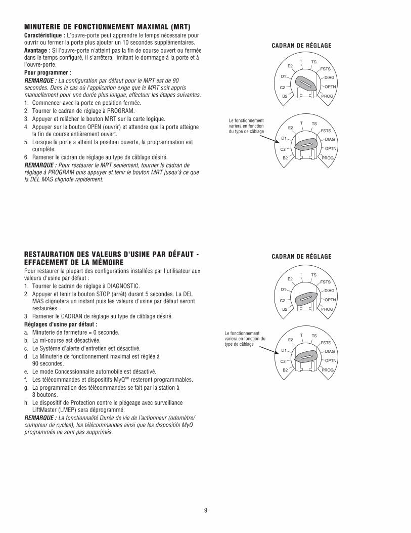
MINUTERIE DE FONCTIONNEMENT MAXIMAL (MRT)Caractéristique : L'ouvre-porte peut apprendre le temps nécessaire pour ouvrir ou fermer la porte plus ajouter un 10 secondes supplémentaires.Avantage : Si l'ouvre-porte n'atteint pas la fin de course ouvert ou fermée dans le temps configuré, il s'arrêtera, limitant le dommage à la porte et à l'ouvre-porte. Pour programmer :REMARQUE : La configuration par défaut pour le MRT est de 90 secondes. Dans le cas où l'application exige que le MRT soit appris manuellement pour une durée plus longue, effectuer les étapes suivantes.1. Commencer avec la porte en position fermée.2. Tourner le cadran de réglage à PROGRAM.3. Appuyer et relâcher le bouton MRT sur la carte logique.4. Appuyer sur le bouton OPEN (ouvrir) et attendre que la porte atteigne
la fin de course entièrement ouvert.5. Lorsque la porte a atteint la position ouverte, la programmation est
complète.6. Ramener le cadran de réglage au type de câblage désiré.REMARQUE : Pour restaurer le MRT seulement, tourner le cadran de réglage à PROGRAM puis appuyer et tenir le bouton MRT jusqu'à ce que la DEL MAS clignote rapidement.
Le fonctionnement variera en fonction du type de câblage
CADRAN DE RÉGLAGE
RESTAURATION DES VALEURS D'USINE PAR DÉFAUT - EFFACEMENT DE LA MÉMOIREPour restaurer la plupart des configurations installées par l'utilisateur aux valeurs d'usine par défaut :1. Tourner le cadran de réglage à DIAGNOSTIC.2. Appuyer et tenir le bouton STOP (arrêt) durant 5 secondes. La DEL
MAS clignotera un instant puis les valeurs d'usine par défaut seront restaurées.
3. Ramener le CADRAN de réglage au type de câblage désiré.Réglages d'usine par défaut :a. Minuterie de fermeture = 0 seconde.b. La mi-course est désactivée.c. Le Système d'alerte d'entretien est désactivé.d. La Minuterie de fonctionnement maximal est réglée à 90 secondes.e. Le mode Concessionnaire automobile est désactivé.f. Les télécommandes et dispositifs MyQMD resteront programmables.g. La programmation des télécommandes se fait par la station à 3 boutons.h. Le dispositif de Protection contre le piégeage avec surveillance
LiftMaster (LMEP) sera déprogrammé.REMARQUE : La fonctionnalité Durée de vie de l’actionneur (odomètre/compteur de cycles), les télécommandes ainsi que les dispositifs MyQ programmés ne sont pas supprimés.
Le fonctionnement variera en fonction du type de câblage
CADRAN DE RÉGLAGE
ENTRETIENPÉRIODICITÉS D'ENTRETIENPour utilisation avec le Système d'alerte d'entretien.Vérifier aux intervalles énumérés dans le tableau suivant :
COMMENT COMMANDER LES PIÈCES DE RECHANGENOTRE IMPORTANTE ORGANISATION DE SERVICE COUVRE
L'AMÉRIQUE
Des renseignements concernant l'installation et le service sont disponibles. Appelez notre numéro SANS FRAIS :
1-800-528-2806 - www.liftmaster.com
Pour éviter des BLESSURES personnelles SÉRIEUSES ou la MORT :• Déconnecter l'alimentation électrique AVANT d'effectuer TOUT
ajustement ou entretien.• TOUT entretien DOIT être effectué par un technicien formé en
systèmes de porte.
ATTENTION
AVERTISSEMENT AVERTISSEMENT
AVERTISSEMENT AVERTISSEMENT
WARNING
CAUTION
WARNING
WARNING
PRECAUCIÓN ADVERTENCIA
ADVERTENCIA ADVERTENCIA
FONCTION DE DURÉE DE VIE DE L'OUVRE-PORTE (ODOMÈTRE/COMPTEUR DE CYCLES)L'ouvre-porte est muni d'un odomètre pour afficher depuis combien de mois et de cycles l'ouvre-porte a fonctionné depuis le moment où il a été installé. Cette caractéristiques peut aider à déterminer depuis combien de temps l'ouvre-porte a été en service.1. Commencer avec la porte en position fermée.2. Tourner le cadran de réglage à DIAG (mode diagnostique).3. Appuyer et relâcher le bouton MAS sur la carte logique.4. Appuyer et relâcher le bouton MRT sur la carte logique.5. Lest témoins ouvert et fermé clignoteront. OPEN (ouvrir) pour chaque 5000 cycles et CLOSE (fermer) pour chaque 3 mois.6. Ramener le CADRAN DE RÉGLAGE au type de câblage désiré.REMARQUE : Si l'ouvre-porte n'a pas atteint 5000 cycles ou 3 mois, il n'y aura aucune indication.
ÉLÉMENT
Chaîne d'entraînement
Pignons
Embrayage
Courroie
Fixations
Déconnexion manuelle
Roulements et arbres
Protection contre le piégeage avec surveillance LiftMaster (LMEP)
PROCÉDURE
Vérifier s'il y a un mou excessif. Vérifier et ajuster si nécessaire.Lubrifier.
Vérifier si les vis de serrage sont bien serrées.
Vérifier et ajuster si nécessaire.
Vérifier la condition et la tension.
Vérifier et resserrer si nécessaire.
Vérifier et faire fonctionner.
Vérifier l'usure et lubrifier.
Vérifier l'alignement et la fonctionnalité.
FREIN (LE CAS ÉCHÉANT)Un frein électrique est disponible en option pour certains modèles. Le frein est ajusté en usine et ne devrait pas nécessiter d'ajustement supplémentaire pour la durée de vie de l'ensemble de frein.Inspecter les plaquettes de frein et remplacer l'ensemble de frein si nécessaire.REMARQUE : Votre ouvre-porte peut sembler différent de l'ouvre-porte montré.
REMARQUE : Pour les instructions de dépannage, référez-vous au Manuel d’Installation.
© 2014, The Chamberlain Group, Inc. All Rights Reserved01-36820 Tous droits réservés