buckling analysis of grid-stiffened...
TRANSCRIPT
11th World Congress on Computational Mechanics (WCCM XI)5th European Conference on Computational Mechanics (ECCM V)
6th European Conference on Computational Fluid Dynamics (ECFD VI)E. Onate, J. Oliver and A. Huerta (Eds)
BUCKLING ANALYSIS OF GRID-STIFFENED COMPOSITE SHELLS
Dan WANG and Mostafa ABDALLA
Delft University of Technology, 2629 HS Delft, The Netherlandse-mail: [email protected], [email protected]
Key words: Buckling, Grid-Stiffened Structures, Composite, Homogenization Techniques,Bloch Wave Theory
Abstract. There is a renewed interest in grid-stiffened composite structures; they are not onlycompetitive with conventional stiffened constructions and sandwich shells in terms of weightbut also enjoy superior damage tolerance properties. In this paper, both global and local struc-tural instabilities are investigated for grid-stiffened composite panels using homogenization the-ory. Characteristic cell configurations with periodic boundary constraints are employed fororthogrid- and isogrid-stiffened shells in order to smear the stiffened panel into an equivalen-t unstiffened shell. Homogenized properties corresponding to classical lamination theory areobtained by matching the strain energy of the stiffened and equivalent cells. Global bucklinganalysis is carried out based on the homogenized shell properties. Bloch wave theory is adopt-ed to calculate the local buckling load of grid-stiffened shells, where the interaction of adjacentcells is fully taken into account. Moreover, instead of considering skin buckling and stiffenercrippling separately, as is commonly done, the skin and stiffeners are assembled together atthe level of the characteristic cell. The critical instabilities can be captured whether they arerelated to the skin or stiffener or their interaction. The proposed combination of global/localmodels can also be used to predict the material failure of a structure. Numerical examples oforthogrid- and isogrid-stiffened isotropic panels show that the local buckling loads predictedby the proposed method match finite element calculations better than semi-analytical methodsbased on assumptions and idealisations. The proposed method is further validated using typicalconfigurations of flat composite panels and circular composite cylinders.
1 Introduction
Due to the advantages of lightweight, small manufacturing cost, high strength, high stability,great energy absorption and superior damage tolerance [1, 2, 3, 4], grid-stiffened composite pan-els have been applied in aerospace engineering for payload fairings of launch vehicles and forload-bearing structures of satellites. Usually, three basic types of grids, i.e., isogrid, orthogrid,and angle-grid, as shown in Fig. 1, are used in practical applications.
1

Dan WANG and Mostafa ABDALLA
(a) Orthogrid (b) Isogrid (c) Anglegrid
Figure 1: Basic types of grid-stiffened panels.
Many researchers have devoted themselves to studying grid-stiffened composite panels [5,6, 7, 8, 9]. The discrete stiffener and the smeared stiffener methods are two main methods usedto study behaviour of such structures. With the detailed geometry retained, the discrete stiffenermethod, where the skin and stiffeners are modeled separately with the compatibility maintainedat the interface [7], has the ability to capture both global and local behaviour and guarantee highaccuracy [8]. However, using the detailed geometry is not only computationally expensive forlarge structures but also precludes the application of the discrete method in downstream designoptimization due to the difficulty of automatic remeshing for changeable geometry. Instead, thesmeared stiffener method, where a grid-stiffened structure is represented by an equivalent ho-mogeneous panel, only involves simple geometry without any detailed geometric informationand therefore leads to better computational efficiency and provides a flexible and suitable in-terface with design optimization. However, as proved by researchers [8], the smeared stiffenermethod is only accurate for calculating global buckling and deficient for local buckling.
Homogenization theory has been widely used in calculating effective properties of a hetero-geneous medium. By using asymptotic expansions and the assumption of periodicity, physicalquantities can be evaluated on two different levels: the macroscopic and microscopic, wherethe former implies slow variation and the latter implies rapid oscillations [10]. Two differentfamilies of numerical methods based on Finite Element Method and Fast Fourier Transform-s, respectively, were compared to obtain the effective properties of composites with periodicmicrostructure [11]. In this work, two specific features of periodic homogenization includingperiodicity conditions and strain or stress control were presented in details. As an extension ofa homogeneous Love-Kirchhoff model [12], a homogenized Reissner-Mindlin model with theshear effects of thick plates taken into account was proposed, where the shear constants weredetermined by an auxiliary 3D boundary value problem [13]. Using the full gradient of thebending moment instead of only the mixed shear forces, the Bending-Gradient theory [14, 15]took advantage of the higher accuracy of both deflection and local stresses than the Reissner-Mindlin theory for heterogeneous plates and was further applied to a folded core sandwich panel[16] and a periodic beam lattice [17].
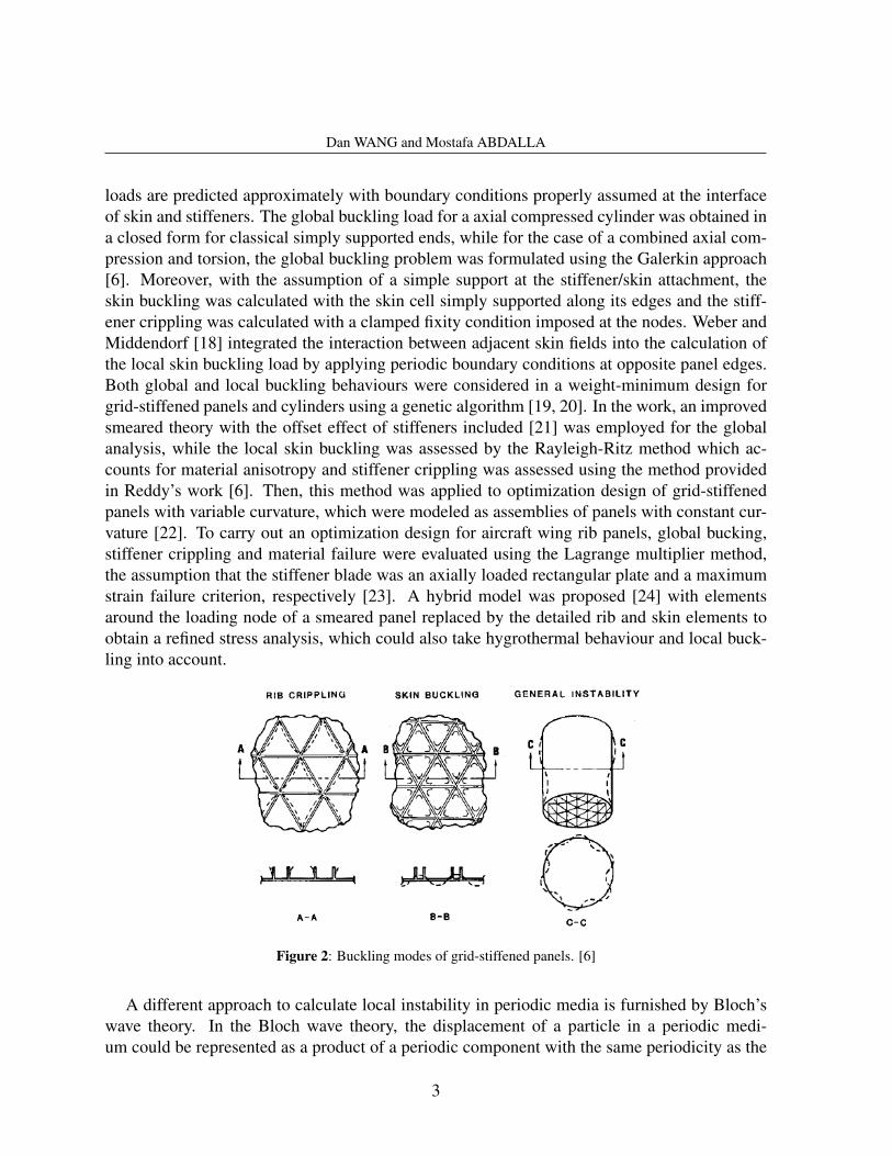
Grid-stiffened panels may fail in three different modes of rib/stiffener crippling, skin buck-ling and global buckling, as show in Fig. 2, where the former two are known as local buckling.To increase its service life, a grid-stiffened structure is usually designed to localize bucklingto ensure that global buckling happens after local buckling. Practically, global buckling loadsof grid-stiffened panels are usually assessed using the smeared method, while local buckling
2
Dan WANG and Mostafa ABDALLA
loads are predicted approximately with boundary conditions properly assumed at the interfaceof skin and stiffeners. The global buckling load for a axial compressed cylinder was obtained ina closed form for classical simply supported ends, while for the case of a combined axial com-pression and torsion, the global buckling problem was formulated using the Galerkin approach[6]. Moreover, with the assumption of a simple support at the stiffener/skin attachment, theskin buckling was calculated with the skin cell simply supported along its edges and the stiff-ener crippling was calculated with a clamped fixity condition imposed at the nodes. Weber andMiddendorf [18] integrated the interaction between adjacent skin fields into the calculation ofthe local skin buckling load by applying periodic boundary conditions at opposite panel edges.Both global and local buckling behaviours were considered in a weight-minimum design forgrid-stiffened panels and cylinders using a genetic algorithm [19, 20]. In the work, an improvedsmeared theory with the offset effect of stiffeners included [21] was employed for the globalanalysis, while the local skin buckling was assessed by the Rayleigh-Ritz method which ac-counts for material anisotropy and stiffener crippling was assessed using the method providedin Reddy’s work [6]. Then, this method was applied to optimization design of grid-stiffenedpanels with variable curvature, which were modeled as assemblies of panels with constant cur-vature [22]. To carry out an optimization design for aircraft wing rib panels, global bucking,stiffener crippling and material failure were evaluated using the Lagrange multiplier method,the assumption that the stiffener blade was an axially loaded rectangular plate and a maximumstrain failure criterion, respectively [23]. A hybrid model was proposed [24] with elementsaround the loading node of a smeared panel replaced by the detailed rib and skin elements toobtain a refined stress analysis, which could also take hygrothermal behaviour and local buck-ling into account.
Figure 2: Buckling modes of grid-stiffened panels. [6]
A different approach to calculate local instability in periodic media is furnished by Bloch’swave theory. In the Bloch wave theory, the displacement of a particle in a periodic medi-um could be represented as a product of a periodic component with the same periodicity as the
3
Dan WANG and Mostafa ABDALLA
medium and periodic function with an arbitrary wavelength. According to this special represen-tation, wave propagation in periodic beams and stiffened plates was evaluated [25, 26]. Then,it was proved that the Bloch wave theory had the ability to determine the onset of instability inperiodic solids [27]. A great body of related work was done by Triantafyllidis and co-workers[4, 28, 29, 30, 31] to investigate critical material instability in periodic solids. In their work,concepts of a micro-failure surface and a macro-failure surface were introduced to describe thelocus of first microscopic bifurcation points and points with a macroscopic loss of ellipticity, re-spectively. The distinction between onsets of microscopic and macroscopic material instabilityis whether the wavelength is commensurate with the unit cell dimension or not. Research hasshowed that the micro-failure surface of an infinite perfectly periodic structure is a lower boundof that of a finite structure, and an upper bound of that of a finite structure with imperfections[30]. Applications of the Bloch wave theory in two-dimensional periodic composites showedthat the interstitial stiffness had an important influence on the nature of the critical failure mode[28]. Similar work has been done by Ohno and co-workers [32, 33] to establish the criticalstates for square honeycombs and Kelvin cell foams under compression loadings.
As clearly illustrated in references [34, 35], existing methods based on the Bloch wave the-ory focus on material failure where the material deforms inside the plane as a failure mode.In this paper, the out-of-plane instability of grid-stiffened panels is characterized by the Blochwave theory. In contrast to the existing methods used to detect material failure, only local insta-bility can be investigated in this case, while global instability is evaluated using the equivalentunstiffened panel with average material properties.
The rest of this paper is devoted to a description of the homogenization approach and theuse of Bloch’s wave theory in detecting local instability of grid-stiffened structure. Section3 presents an overview of the homogenization approach and the smearing process of a grid-stiffened panel. Section 4 develops the Bloch wave theory and reduces the computation to asymmetric generalized eigenvalue problem. Section 5 presents a number of numerical examplesof flat and curved grid-stiffened structures and comparison to published results and detailedfinite element calculations. Finally, section 6 provides conclusions.
2 Homogenization of a grid-stiffened composite panel
2.1 Homogenization theory
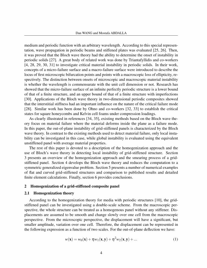
According to the homogenization theory for media with periodic structures [10], the grid-stiffened panel can be investigated using a double-scale scheme. From the macroscopic per-spective, the whole structure can be treated as a homogenous panel without any stiffener. Dis-placements are assumed to be smooth and change slowly over one cell from the macroscopicperspective. From the microscopic perspective, the displacement will have a significant, butsmaller amplitude, variation over one cell. Therefore, the displacement can be represented inthe following expression as a function of two scales. For the out-of-plane deflection we have:
w(x) = w0(x)+ηw1(x,y)+η2w2(x,y)+ ... (1)
4
Dan WANG and Mostafa ABDALLA
where y = x/η , and η is a small parameter representing the ratio of cell dimension to thedimension of the solid.
Correspondingly, the curvature vector can be expressed as:
w,xx(x) =1η
w1,yy(x,y)+(w0,xx(x)+w2,yy(x,y))+η(w1,xx(x,y)+w3,yy(x,y))+ ... (2)
For the above equation, if w1,yy 6= 0, the first item in the right part of that equation willbecome unbounded as η → 0. Therefore, we require w1 = 0 and Eq. (2) can be rewritten as:
κκκ(x) = κκκ0(x)+κκκ1(x,y)+ηκκκ2(x,y)+ ... (3)
where κκκ0 is the curvature due to the macroscopic variation and κκκ1 due to the microscopicvariation. Higher order terms will not be considered in this work.
Similarly, the in-plane displacement is represented as:
u(x) = u0(x)+ηu1(x,y)+η2u2(x,y)+ ... (4)
and the corresponding strains:
εεε(x) = εεε0(x)+εεε1(x,y)+ηεεε2(x,y)+ ... (5)
The displacement fields w2(x,y) and u1(x,y) are assumed to be periodic in y.
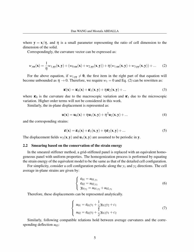
2.2 Smearing based on the conservation of the strain energy
In the smeared stiffener method, a grid-stiffened panel is replaced with an equivalent homo-geneous panel with uniform properties. The homogenization process is performed by equatingthe strain energy of the equivalent model to be the same as that of the detailed cell configuration.
For simplicity, consider a cell configuration periodic along the y1 and y2 directions. The cellaverage in-plane strains are given by:
ε01 = u01,y1
ε02 = u02,y2
γ01y2 = u01,y2 +u02,y1
(6)
Therefore, these displacements can be represented analytically.u01 = ε01y1 +
12
γ012y2 + c1
u02 = ε02y2 +12
γ012y1 + c2
(7)
Similarly, following compatible relations hold between average curvatures and the corre-sponding deflection u03:
5
Dan WANG and Mostafa ABDALLA
κ01 = u03,y1y1
κ02 = u03,y2y2
κ012 = 2u03,y1y2
(8)
The slowly varying out-of-plane deflection may be represented as follows:
u03 =12
y1 y2[ κ01 κ012/2
κ012/2 κ02
]y1y2
+ c3y1 + c4y2 + c5
=12(κ01y2
1 +κ02y22 +κ012y1y2)+ c3y1 + c4y2 + c5 (9)
In the above expressions of Eqs. (7) and (9), items including constants c1, c2 and c5 denoterigid body translations and items including constants c3 and c4 denote rigid body rotations,which have no contribution to the strain energy. Therefore, all these constants could be set tozero to simplify the expressions.
The rotations θ01 = u03,y2 , θ02 =−u03,y1 are given by:θ01 = κ02y2 +
12
κ012y1
θ02 =−κ01y1−12
κ012y2
(10)
The periodic part of the displacement vector does not contribute to the difference in totaldisplacement between corresponding nodes on opposite sides of a characteristic cell. Thus thefollowing boundary conditions apply:
∆u1 = ε01∆y1 +12
γ012∆y2
∆u2 = ε02∆y2 +12
γ012∆y1
∆u3 =12
κ012∆(y1y2)
∆θ1 = κ02∆y2 +12
κ012∆y1
∆θ2 =−κ01∆y1−12
κ012∆y2
(11)
Herein, the center of the cell is set to the origin of the coordinate system to simplify the equa-tions.
The total strain energy is given by:
U =12
∫Ωc
ΓT0 CΓ0dΩc (12)
Here, Γ0 = ε0ε0ε0 κ0κ0κ0T and symbol C denotes the equivalent material stiffness matrix of thesmeared panel.
6
Dan WANG and Mostafa ABDALLA
The discrete version takes the form:
U =12
uT Ku (13)
By rewriting the displacement constraints of Eq. (11) in a matrix form Lu = DΓ0, we candevelop an augmented form of the potential energy for a system without any external force.
Π =12
uT Ku−λT (Lu−DΓ0) (14)
Using the minimum potential energy principle, we have:∂Π
∂u= Ku−LT
λ = 0∂Π
∂λ= Lu−DΓ0 = 0
(15)
which leads to [K LT
L 0
]uλ
=
0D
Γ0 (16)
Solving the above system with imposing strains and curvatures evaluated in the macroscopiclevel as ’generalized loading’ [11], displacements in the local region are obtained. Then, localstresses, which determines the material failure, can be acquired.
The solution of Eq. (16) takes the form of u=UΓ0. With a combination of Eq.s (12) and (13)and a substitution of elementary strain and curvature states expressed by an unitary matrix intoEq. (12), the equivalent stiffness matrix of the smeared panel can be obtained via the followingexpression.
Ce f f =1Ac
UT KU (17)
3 Local buckling prediction
For a characteristic cell of a grid-stiffened panel, the equilibrium of its finite element modelcould be expressed as follows: Kt
1,1 Kt1,2:(n−1) Kt
1,nKt
2:(n−1),1 Kt2:(n−1),2:(n−1) Kt
2:(n−1),nKt
n,1 Kt2:(n−1),n Kt
n,n
u1u2:(n−1)
un
=
f10fn
(18)
where Kt is the tangent stiffness matrix. u and f are the displacement and force vectors, respec-tively. Subscripts 1 and n denote the starting part and the ending part of the periodic cell alongthe direction of the wave propagation, respectively.
7
Dan WANG and Mostafa ABDALLA
According to the Bloch wave theory, displacement vectors of a point in a 2D periodic struc-ture coulcand be expressed in the following form [30]:
u(y1,y2) = u(y1,y2)exp[
i(
m1y1
s1+
m2y2
s2
)](19)
where m1 and m2 are dimensionless wave numbers and s1 and s2 are the cell lengths along twodifferent periodic axes. u(y1,y2) is a periodic function following the same cycle of a represen-tative cell, which satisfies:
u(y1 +n1s1,y2 +n2s2) = u(y1,y2) (20)
In the above equation, n1 and n2 are arbitrary integers.The representation of u in Eq. (19) implies the following relationship at the periodic bound-
aries:
un = µµµ(eim1 ,eim2)u1 (21)
Construct a matrix as follows:
L =−µµµ 0 I
T (22)
with µµµ denotes the conjugate matrix of µµµ . Note that the matrix L is identical to that used in thesmearing process when the wave numbers equal to zero. Then, the conjugate transpose matrixof L could be expressed as:
L∗ =−µµµ 0 I
(23)
It is easy to conclude that:
L∗u = 0 (24)
The forces between boundary nodes on the opposite edges obey the same relationship as thedisplacements expressed by Eq. (21) but with opposite directions. Therefore, the followingequation is satisfied.
f = Lfn (25)
With the substitution of Eqs. (24) and (25), Eq. (18) could be rewritten as [31]:[Kt LL∗ 0
]u−fn
= 0 (26)
The generalized eigenvalues of the above equation are the buckling loads of the periodicpanel. The minimum eigenvalue Λm(m1,m2) for prescribed dimensionless wave numbers from
8
Dan WANG and Mostafa ABDALLA
2nπ to (2n+2)π defines the critical buckling load parameter surface, where n denotes an non-negative integer. Due to the periodicity and symmetry, the range of m1 and m2 can be limited to[0,π]. Therefore, the critical buckling load defined as the minimum value of all the Λm(m1,m2)satisfies the following equation [30].
Λc = min0≤m1,m2≤π
Λm(m1,m2) (27)
Actually, in contrast to periodic solid, a grid-stiffened thin-walled panel with infinite dimen-sions always buckles at zero, which belongs to global instability with a long wavelength. In thiscase, the local minimum value of Eq. (27) with the wave numbers far away from zero belongs tothe range of a short wavelength, which is the local critical buckling load for a finite panel. Thelocal buckling load of a finite grid-stiffened composite panel is obtained within this framework.
4 Numerical examples
In this section, numerical examples are used to demonstrate the effectiveness of the proposedapproach. First, the local buckling loads of an isotropic simply supported panel predicted bythe proposed method are compared with those by a semi-analytic method [18]. Then, numericalpredictions of the proposed method are presented for typical orthogrid- and isogrid-stiffenedcomposite flat panels and circular cylinders. For the examples, detailed finite element modelsprovide the basis for validating the accuracy of the proposed method.
4.1 A flat isotropic panel
A comparison between local buckling loads of the proposed method and a semi-analyticalskin buckling calculation method [18] is carried out in the example for orthogrid- and isogrid-stiffened isotropic panels under axial compression. In Weber and Middendorf’s work, bucklingload coefficients of both single panels with simply supported boundary conditions and skinfields with periodic boundary conditions imposed at opposite panel edges are provided. Exceptfor the case of the rectangular panel under compression, there are evident differences betweenthe results predicted by these two different assumptions. The results of both cases are consideredin the comparison. The semi-analytical buckling results of the rectangular panel with clampedboundary conditions [36] are also included.
The different cell configurations involved for orthogrid and isogrid are illustrated in Fig.s3(a) and (b), respectively. To eliminate the effect of dimensions and material properties, adimensionless buckling load coefficient k is used with an expression as follows:
k =Ncrb2
π2D(28)
where
D =t3E
12(1−ν2)(29)
9
Dan WANG and Mostafa ABDALLA
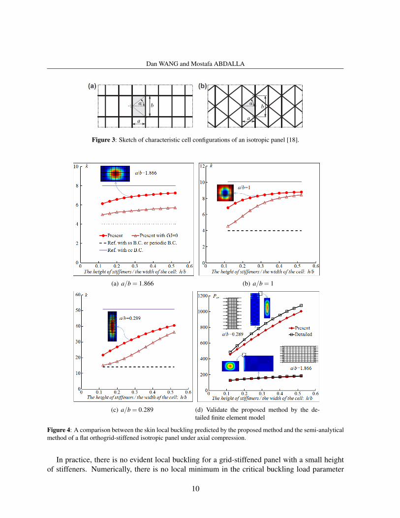
Figure 3: Sketch of characteristic cell configurations of an isotropic panel [18].
(a) a/b = 1.866 (b) a/b = 1
(c) a/b = 0.289 (d) Validate the proposed method by the de-tailed finite element model
Figure 4: A comparison between the skin local buckling predicted by the proposed method and the semi-analyticalmethod of a flat orthogrid-stiffened isotropic panel under axial compression.
In practice, there is no evident local buckling for a grid-stiffened panel with a small heightof stiffeners. Numerically, there is no local minimum in the critical buckling load parameter
10
Dan WANG and Mostafa ABDALLA
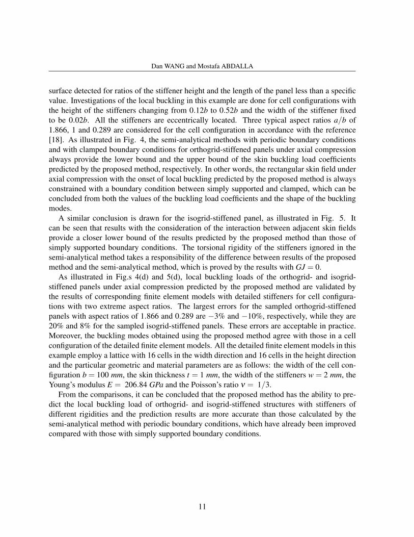
surface detected for ratios of the stiffener height and the length of the panel less than a specificvalue. Investigations of the local buckling in this example are done for cell configurations withthe height of the stiffeners changing from 0.12b to 0.52b and the width of the stiffener fixedto be 0.02b. All the stiffeners are eccentrically located. Three typical aspect ratios a/b of1.866, 1 and 0.289 are considered for the cell configuration in accordance with the reference[18]. As illustrated in Fig. 4, the semi-analytical methods with periodic boundary conditionsand with clamped boundary conditions for orthogrid-stiffened panels under axial compressionalways provide the lower bound and the upper bound of the skin buckling load coefficientspredicted by the proposed method, respectively. In other words, the rectangular skin field underaxial compression with the onset of local buckling predicted by the proposed method is alwaysconstrained with a boundary condition between simply supported and clamped, which can beconcluded from both the values of the buckling load coefficients and the shape of the bucklingmodes.
A similar conclusion is drawn for the isogrid-stiffened panel, as illustrated in Fig. 5. Itcan be seen that results with the consideration of the interaction between adjacent skin fieldsprovide a closer lower bound of the results predicted by the proposed method than those ofsimply supported boundary conditions. The torsional rigidity of the stiffeners ignored in thesemi-analytical method takes a responsibility of the difference between results of the proposedmethod and the semi-analytical method, which is proved by the results with GJ = 0.
As illustrated in Fig.s 4(d) and 5(d), local buckling loads of the orthogrid- and isogrid-stiffened panels under axial compression predicted by the proposed method are validated bythe results of corresponding finite element models with detailed stiffeners for cell configura-tions with two extreme aspect ratios. The largest errors for the sampled orthogrid-stiffenedpanels with aspect ratios of 1.866 and 0.289 are −3% and −10%, respectively, while they are20% and 8% for the sampled isogrid-stiffened panels. These errors are acceptable in practice.Moreover, the buckling modes obtained using the proposed method agree with those in a cellconfiguration of the detailed finite element models. All the detailed finite element models in thisexample employ a lattice with 16 cells in the width direction and 16 cells in the height directionand the particular geometric and material parameters are as follows: the width of the cell con-figuration b = 100 mm, the skin thickness t = 1 mm, the width of the stiffeners w = 2 mm, theYoung’s modulus E = 206.84 GPa and the Poisson’s ratio ν = 1/3.
From the comparisons, it can be concluded that the proposed method has the ability to pre-dict the local buckling load of orthogrid- and isogrid-stiffened structures with stiffeners ofdifferent rigidities and the prediction results are more accurate than those calculated by thesemi-analytical method with periodic boundary conditions, which have already been improvedcompared with those with simply supported boundary conditions.
11
Dan WANG and Mostafa ABDALLA
(a) a/b = 1.866 (b) a/b = 1
(c) a/b = 0.289 (d) Validate the proposed method by the detailedfinite element model
Figure 5: A comparison between the skin local buckling predicted by the proposed method and the semi-analyticalmethod of a flat isogrid-stiffened isotropic panel under axial compression.
4.2 A flat composite panel
The example is a simply supported flat grid-stiffened composite panel, which represents ageneric structural component of a transport helicopter fuselage, as studied in reference [20].The flat panel with the length of 4376.4 mm and the width of 1587.7 mm is stiffened on oneside by orthogrid or isogrid stiffeners. The skin laminate has an eight-plys symmetric layup of(±45/90/0)s with each ply thickness being 0.1524 mm. The nominal ply mechanical propertiesare E11 = 139.31 GPa, E22 = 13.103 GPa, G12 = G13 = G23 = 5.0345 GPa, ν12 = 0.3 andρ = 1590 kg/mm3. All the stiffeners are made of 0-deg material with a height of h = 12.9 mmand a width of w = 1.524 mm.
The parameters of the grid-stiffened flat panel are given in Table 1. In the example, the angles
12
Dan WANG and Mostafa ABDALLA
between different stiffeners are set to be 60o for the isogrid cell configurations. The weights ofthe involved orthogrid- and isogrid-stiffened flat panels are very close.
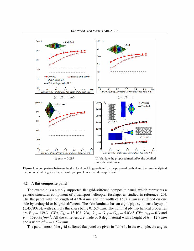
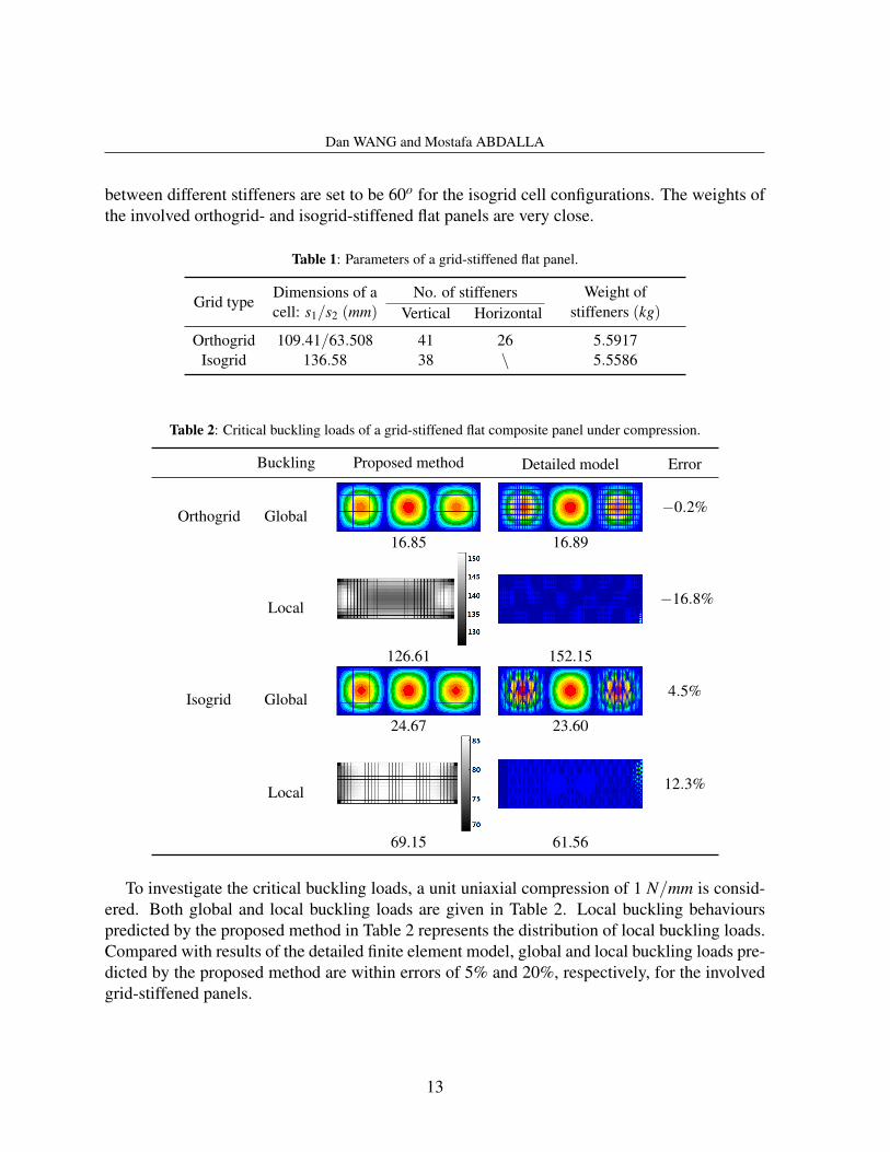
Table 1: Parameters of a grid-stiffened flat panel.
Grid typeDimensions of a No. of stiffeners Weight ofcell: s1/s2 (mm) Vertical Horizontal stiffeners (kg)
Orthogrid 109.41/63.508 41 26 5.5917Isogrid 136.58 38 \ 5.5586
Table 2: Critical buckling loads of a grid-stiffened flat composite panel under compression.
Buckling Proposed method Detailed model Error
Orthogrid Global −0.2%
16.85 16.89
Local −16.8%
126.61 152.15
Isogrid Global 4.5%
24.67 23.60
Local 12.3%
69.15 61.56
To investigate the critical buckling loads, a unit uniaxial compression of 1 N/mm is consid-ered. Both global and local buckling loads are given in Table 2. Local buckling behaviourspredicted by the proposed method in Table 2 represents the distribution of local buckling loads.Compared with results of the detailed finite element model, global and local buckling loads pre-dicted by the proposed method are within errors of 5% and 20%, respectively, for the involvedgrid-stiffened panels.
13
Dan WANG and Mostafa ABDALLA
4.3 A composite circular cylinder
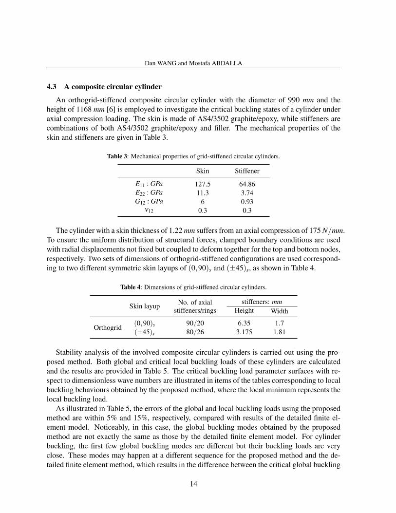
An orthogrid-stiffened composite circular cylinder with the diameter of 990 mm and theheight of 1168 mm [6] is employed to investigate the critical buckling states of a cylinder underaxial compression loading. The skin is made of AS4/3502 graphite/epoxy, while stiffeners arecombinations of both AS4/3502 graphite/epoxy and filler. The mechanical properties of theskin and stiffeners are given in Table 3.
Table 3: Mechanical properties of grid-stiffened circular cylinders.
Skin Stiffener
E11 : GPa 127.5 64.86E22 : GPa 11.3 3.74G12 : GPa 6 0.93
ν12 0.3 0.3
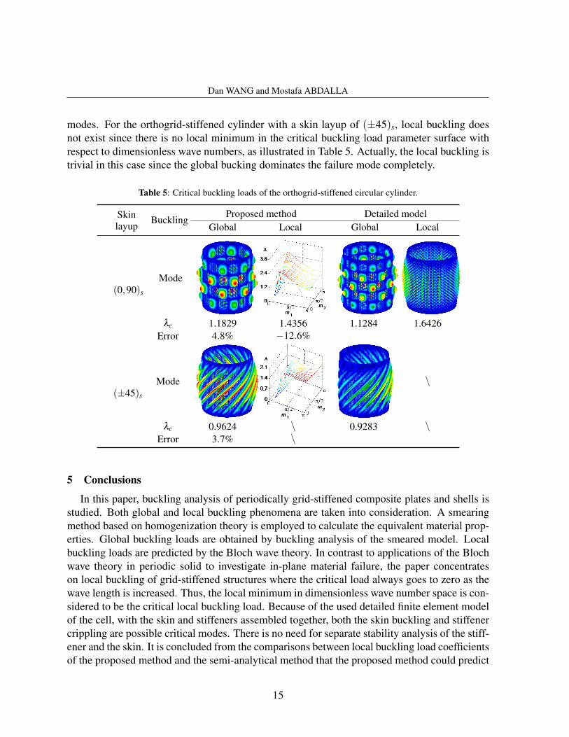
The cylinder with a skin thickness of 1.22 mm suffers from an axial compression of 175 N/mm.To ensure the uniform distribution of structural forces, clamped boundary conditions are usedwith radial displacements not fixed but coupled to deform together for the top and bottom nodes,respectively. Two sets of dimensions of orthogrid-stiffened configurations are used correspond-ing to two different symmetric skin layups of (0,90)s and (±45)s, as shown in Table 4.
Table 4: Dimensions of grid-stiffened circular cylinders.
Skin layup No. of axial stiffeners: mmstiffeners/rings Height Width
Orthogrid(0,90)s 90/20 6.35 1.7(±45)s 80/26 3.175 1.81
Stability analysis of the involved composite circular cylinders is carried out using the pro-posed method. Both global and critical local buckling loads of these cylinders are calculatedand the results are provided in Table 5. The critical buckling load parameter surfaces with re-spect to dimensionless wave numbers are illustrated in items of the tables corresponding to localbuckling behaviours obtained by the proposed method, where the local minimum represents thelocal buckling load.
As illustrated in Table 5, the errors of the global and local buckling loads using the proposedmethod are within 5% and 15%, respectively, compared with results of the detailed finite el-ement model. Noticeably, in this case, the global buckling modes obtained by the proposedmethod are not exactly the same as those by the detailed finite element model. For cylinderbuckling, the first few global buckling modes are different but their buckling loads are veryclose. These modes may happen at a different sequence for the proposed method and the de-tailed finite element method, which results in the difference between the critical global buckling
14
Dan WANG and Mostafa ABDALLA
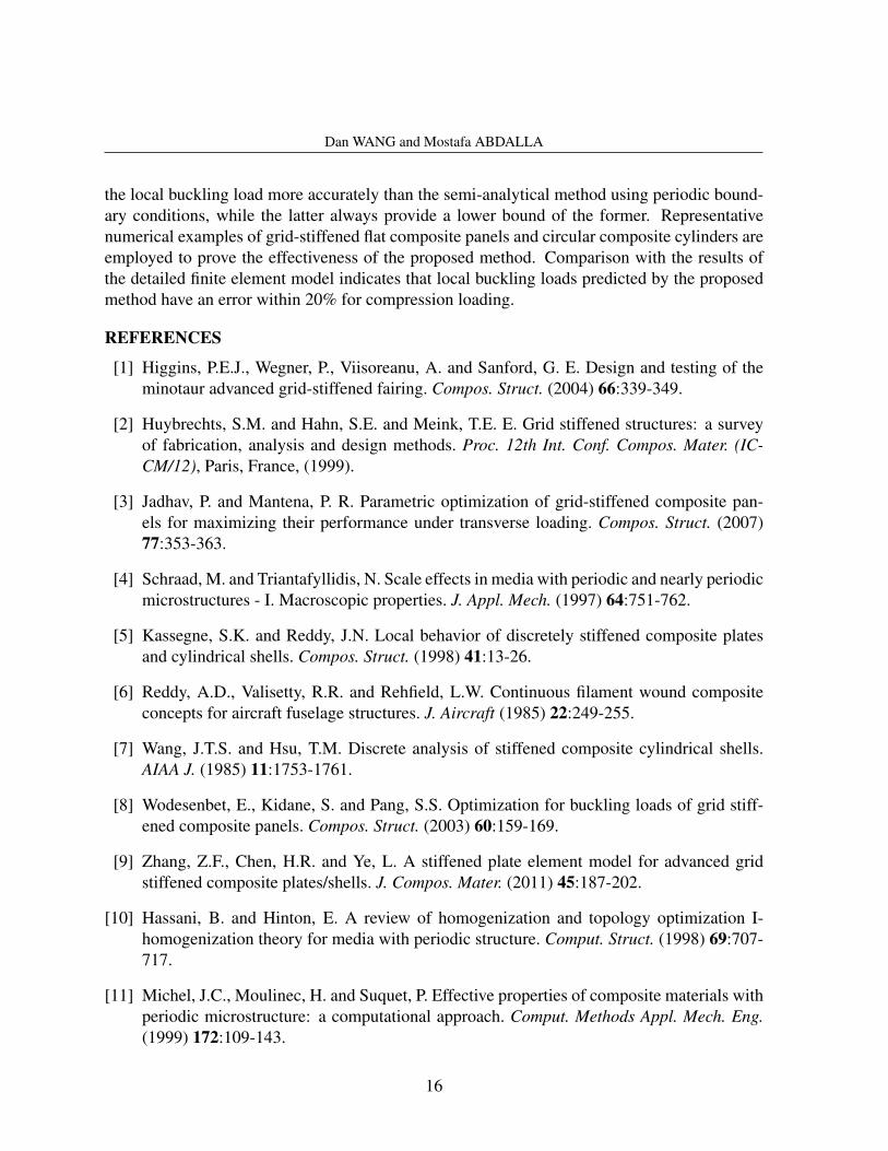
modes. For the orthogrid-stiffened cylinder with a skin layup of (±45)s, local buckling doesnot exist since there is no local minimum in the critical buckling load parameter surface withrespect to dimensionless wave numbers, as illustrated in Table 5. Actually, the local buckling istrivial in this case since the global bucking dominates the failure mode completely.
Table 5: Critical buckling loads of the orthogrid-stiffened circular cylinder.
Skin BucklingProposed method Detailed model
layup Global Local Global Local
(0,90)s
Mode
λc 1.1829 1.4356 1.1284 1.6426Error 4.8% −12.6%
(±45)s
Mode \
λc 0.9624 \ 0.9283 \Error 3.7% \
5 Conclusions
In this paper, buckling analysis of periodically grid-stiffened composite plates and shells isstudied. Both global and local buckling phenomena are taken into consideration. A smearingmethod based on homogenization theory is employed to calculate the equivalent material prop-erties. Global buckling loads are obtained by buckling analysis of the smeared model. Localbuckling loads are predicted by the Bloch wave theory. In contrast to applications of the Blochwave theory in periodic solid to investigate in-plane material failure, the paper concentrateson local buckling of grid-stiffened structures where the critical load always goes to zero as thewave length is increased. Thus, the local minimum in dimensionless wave number space is con-sidered to be the critical local buckling load. Because of the used detailed finite element modelof the cell, with the skin and stiffeners assembled together, both the skin buckling and stiffenercrippling are possible critical modes. There is no need for separate stability analysis of the stiff-ener and the skin. It is concluded from the comparisons between local buckling load coefficientsof the proposed method and the semi-analytical method that the proposed method could predict
15
Dan WANG and Mostafa ABDALLA
the local buckling load more accurately than the semi-analytical method using periodic bound-ary conditions, while the latter always provide a lower bound of the former. Representativenumerical examples of grid-stiffened flat composite panels and circular composite cylinders areemployed to prove the effectiveness of the proposed method. Comparison with the results ofthe detailed finite element model indicates that local buckling loads predicted by the proposedmethod have an error within 20% for compression loading.
REFERENCES
[1] Higgins, P.E.J., Wegner, P., Viisoreanu, A. and Sanford, G. E. Design and testing of theminotaur advanced grid-stiffened fairing. Compos. Struct. (2004) 66:339-349.
[2] Huybrechts, S.M. and Hahn, S.E. and Meink, T.E. E. Grid stiffened structures: a surveyof fabrication, analysis and design methods. Proc. 12th Int. Conf. Compos. Mater. (IC-CM/12), Paris, France, (1999).
[3] Jadhav, P. and Mantena, P. R. Parametric optimization of grid-stiffened composite pan-els for maximizing their performance under transverse loading. Compos. Struct. (2007)77:353-363.
[4] Schraad, M. and Triantafyllidis, N. Scale effects in media with periodic and nearly periodicmicrostructures - I. Macroscopic properties. J. Appl. Mech. (1997) 64:751-762.
[5] Kassegne, S.K. and Reddy, J.N. Local behavior of discretely stiffened composite platesand cylindrical shells. Compos. Struct. (1998) 41:13-26.
[6] Reddy, A.D., Valisetty, R.R. and Rehfield, L.W. Continuous filament wound compositeconcepts for aircraft fuselage structures. J. Aircraft (1985) 22:249-255.
[7] Wang, J.T.S. and Hsu, T.M. Discrete analysis of stiffened composite cylindrical shells.AIAA J. (1985) 11:1753-1761.
[8] Wodesenbet, E., Kidane, S. and Pang, S.S. Optimization for buckling loads of grid stiff-ened composite panels. Compos. Struct. (2003) 60:159-169.
[9] Zhang, Z.F., Chen, H.R. and Ye, L. A stiffened plate element model for advanced gridstiffened composite plates/shells. J. Compos. Mater. (2011) 45:187-202.
[10] Hassani, B. and Hinton, E. A review of homogenization and topology optimization I-homogenization theory for media with periodic structure. Comput. Struct. (1998) 69:707-717.
[11] Michel, J.C., Moulinec, H. and Suquet, P. Effective properties of composite materials withperiodic microstructure: a computational approach. Comput. Methods Appl. Mech. Eng.(1999) 172:109-143.
16
Dan WANG and Mostafa ABDALLA
[12] Caillerie, D. Thin elastic and periodic plates. Math. Methods Appl. Sci.) (1984) 6:159-191.
[13] Cecchi, A. and Sab, K. A homogenized Reissner-Mindlin model for orthotropic periodicplate: application to brickwork panels. Int. J. Solids Struct. (2007) 44:6055-6079.
[14] Lebee, A. and Sab, K. A bending-gradient model for thick plates. Part I: Theory. Int. J.Solids Struct. (2011) 48:2878-2888.
[15] Lebee, A. and Sab, K. A bending-gradient model for thick plates. Part II: Closed-formsolutions for cylindrical bending of laminates. Int. J. Solids Struct. (2011) 48:2889-2901.
[16] Lebee, A. and Sab, K. Homogenization of thick periodic plates: application of theBending-Gradient plate theory to a folded core sandwich panel. Int. J. Solids Struct. (2012)49:2778-2792.
[17] Lebee, A. and Sab, K. Homogenization of a space frame as a thick plate: application ofthe Bending-Gradient plate theory to a beam lattice. Comput. Struct. (2013) 127:88-101.
[18] Weber, M.J. and Middendorf, P. Semi-analytical skin buckling of curved orthotropic grid-stiffened shells. Compos. Struct. (2014) 108:616-624.
[19] Jaunky, N., Knight, Jr., N.F. and Ambur, D.R. Optimal design of general stiffened compos-ite circular cylinders for global buckling with strength constraints. Compos. Struct. (1998)41:243-252.
[20] Jaunky, N., Knight, Jr., N.F. and Ambur, D.R. Optimal design of grid-stiffened compositepanels using global and local buckling analyses. J. Aircraft (1998) 35:478-486.
[21] Jaunky, N., Knight, Jr., N.F. and Ambur, D.R. Formulation of an improved smeared s-tiffener theory for buckling analysis of grid-stiffened composite panels. Compos. Part B -Eng. (1996) 27B:519-526.
[22] Ambur, D.R. and Jaunky, N. Optimal design of grid-stiffened panels and shells with vari-able curvature. Compos. Struct. (2001) 52:173-180.
[23] Phillips, J.L. and Gurdal, Z. Analysis and optimum design of geodesically stiffened com-posite panels. Compos. Mater. Des. Anal. WIT Press, Southampton, pp. 509-528, (1990).
[24] Chen, H.J. and Tsai, S.W. Analysis and optimum design of composite grid structures. J.Compos. Mater. (1995) 30:503-533.
[25] Mead, D.J. Free wave propagation in periodically supported infinite beams. J. Sound Vib.(1970) 11:181-197.
[26] Mead, D.J. A new method of analyzing wave propagation in periodic structures; applica-tions to periodic Timoshenko beams and stiffened plates. J. Sound Vib. (1986) 104:9-27.
17
Dan WANG and Mostafa ABDALLA
[27] Geymonat, G., Muller, S. and Triantafyllidis, N. Homogenization of nonlinearly elasticmaterials, microscopic bifurcation and macroscopic loss of rank-one convexity. Arch. Ra-tion. Mech. Anal. (1993) 122:231-291.
[28] Triantafyllidis, N. and Schnaidt, W.C. Comparison of microscopic and macroscopic insta-bilities in a class of two-dimensional periodic composites. J. Mech. Phys. Solids (1993)41:1533-1565.
[29] Triantafyllidis, N. and Bardenhagen, S. The influence of scale size on the stability ofperiodic solids and the role of associated higher order gradient continuum models. J. Mech.Phys. Solids (1996) 44:1891-1928.
[30] Schraad, M. and Triantafyllidis, N. Scale effects in media with periodic and nearly periodicmicrostructures - II. Failure mechanisms. J. Appl. Mech. (1997) 64:763-771.
[31] Gong, L., Kyriakides, S. and Triantafyllidis, N. On the stability of Kelvin cell foams undercompressive loads. J. Mech. Phys. Solids (2005) 53:771-794.
[32] Ohno, N., Okumura, D. and Niikawa, T. Long-wave buckling of elastic square honey-combs subject to in-plane biaxial compression. Int. J. Mech. Sci. (2004) 46:1697-1713.
[33] Okumura, D., Okada, A. and Ohno, N. Buckling behavior of Kelvin open-cell foams under[0 0 1], [0 1 1] and [1 1 1] compressive loads. Int. J. Solids Struct. (2008) 45:3807-3820.
[34] Triantafyllidis, N., Nestorovic, M.D. and Schraad, M.W. Failure surfaces for finitely s-trained two-phase periodic solids under general in-plane loading. J. Appl. Mech. (2006)73:505-515.
[35] Ohno, N., Okumura, D. and Noguchi, H. Microscopic symmetric bifurcation conditionof cellular solids based on a homogenization theory of finite deformation. J. Mech. Phys.Solids (2002) 50:1125-1153.
[36] Galambos, T.V. Guide to stability design criteria for metal structures. John Wiley & Sons,INC, 5th ed. (1998).
18