analysis of stiffened isotropic and composite plate · stiffened plates but the work on composite...
TRANSCRIPT

International Research Journal of Engineering and Technology (IRJET) e-ISSN: 2395 -0056
Volume: 03 Issue: 02 | Feb-2016 www.irjet.net p-ISSN: 2395-0072
© 2016, IRJET ISO 9001:2008 Certified Journal Page 1
Analysis of stiffened isotropic and composite plate
R. R. Singh1, Dr. P. Pal2
1 Research Scholar, Department of Civil Engineering, MNNIT Allahabad, U.P., India 2 Assistant Professor, Department of Civil Engineering, MNNIT Allahabad, U.P., India
---------------------------------------------------------------------***---------------------------------------------------------------------Abstract – This paper deals with the study of stiffened
isotropic and composite plates. Finite element technique is
used to model and analyze the stiffened plates. An attempt has
been made to minimize the deformation of plate without
increasing the volume of material required to buildup the
stiffened plate. It is achieved by arbitrarily varying the length,
thickness and height of stiffener. The results are obtained for
both isotropic and composite plates and recommendations
have been made for both types of stiffened plate.
Key Words: Thin Plate, Composite, Stiffener, FEM, ANSYS.
1. INTRODUCTION Stiffened panels are common structural elements in weight sensitive structural, aerospace and marine applications. Stiffened Plates are extensively used in lock gates, railway wagons, plate girders, highway bridges, aircraft wings, cargo containers, elevated roadways etc. These structural elements can be defined as plates reinforced by a single or a set of beams or ribs on one or both sides of the plate. The benefit of reinforcing a plate by stiffeners lies in remarkable increase of strength and stability while minimum increase of
weight to the overall structures. Stiffened plates can also be
fabricated with ease and simplicity. Many researchers have done numerous work on isotropic stiffened plates but the work on composite stiffened plate is scanty. Mukhopadhyay et al.[1-2] used the eight-noded isoparametric plate bending element to study the large deflection behavior of stiffened plates. The author also proposed a semi-analytical method for the analysis of bare plates and extended it to the static analysis of stiffened plates. Bedair[3] investigated the elastic behavior of stiffened plates under non-uniform edge compression. A finite element model was developed for optimizing separately or simultaneously the critical buckling loads and natural frequencies of the plates per unit volume of the plates/stiffeners by Akl et al.[4]. Li and Xiaohui[5] varied the quantity, the collocation and the geometry of stiffeners to improve the stiffness and the strength of stiffened laminated plates. Authors used higher-order global–local theories to study the bending behavior of stiffened laminated plates. Liu and Wang[6-7] discussed the strengthening effects of stiffener on regular and arbitrarily stiffened plates through a
series of ANSYS buckling strength analyses. The authors through several simulations and comparisons also proved that the strengthening effects of arbitrarily oriented stiffener can be approximated by those of regularly oriented stiffener. Thoi et al.[8] presented the static, free vibration and buckling analyses of eccentrically stiffened plates by the cell-based smoothed discrete shear gap method (CS-FEM-DSG3) using triangular elements. Ahmed and Rameez[9] investigated strengthening effects of regular stiffened plates subjected to uniaxial stress and arbitrarily stiffened plates that are subjected to biaxial stress. Singh et al.[10] presented a parametric study to estimate the maximum deflection and stress in the isotropic stiffened plates. 2. FE MODELLING AND CONVERGENCE STUDIES The modelling of any finite element problem includes generally five steps; a) Defining the material properties of the model, which are presented in Table 1. b) Creating the geometry of the model, c) Discretizing the model into number of finite elements (i.e. meshing of the geometry), d) Applying boundary and loading conditions, e) Solving the problem for its subsequent results.
Table 1: Material Properties
Isotropic Composite
(Orthotropic) Density = 7850 kg/m3 , E = 2 × 10¹¹ Pa, ν =0.3
Density = 154 kg/m3 Ex = 2.09 × 10¹¹ Pa, Ey = 9.450 × 10⁹ Pa, Ez = 9.450 × 10⁹ Pa, Gxy = 5.5 × 10⁹ Pa, Gyz = 3.9 × 10⁹ Pa, Gxz = 5.5 × 10⁹ Pa, νxy = 0.27, νyz = 0.4 , νxz = 0.27
For modeling the isotropic plate, the plate is modelled using SHELL181 element and the stiffener is modelled using SOLID186 element available in the ANSYS Workbench15. Whereas for composite plate, only SHELL181 element is used for modeling both plate and stiffener. The description of SHELL181 and SOLID186 are given below.
SHELL181 is suitable for analyzing thin to moderately-thick shell structures. It is a four-node element with six degrees of

International Research Journal of Engineering and Technology (IRJET) e-ISSN: 2395 -0056
Volume: 03 Issue: 02 | Feb-2016 www.irjet.net p-ISSN: 2395-0072
© 2016, IRJET ISO 9001:2008 Certified Journal Page 2
freedom at each node: translations in the x, y, and z directions, and rotations about the x, y, and z-axes. It is well-suited for linear, large rotation, and/or large strain nonlinear applications. It accounts for follower (load stiffness) effects of distributed pressures. It can be also used for layered applications for modeling composite shells or sandwich construction. The accuracy in modeling composite shells is governed by the first-order shear-deformation theory (usually referred to as Mindlin-Reissner shell theory). SOLID186 is a higher order 3-D 20-node solid element that exhibits quadratic displacement behavior. The element is defined by 20 nodes having three degrees of freedom per node: translations in the nodal x, y, and z directions. The element supports plasticity, hyperelasticity, creep, stress stiffening, large deflection, and large strain capabilities. SOLID186 Homogeneous Structural Solid is well suited to modeling irregular meshes (such as those produced by various CAD/CAM systems).
Table 2: Geometric Dimensions
Bare Plate Stiffened Plate Size of Plate 1000mm×1000mm×
10mm 1000mm×1000mm×8mm
Size of Stiffener
- (L×T×H)*
Total Volume of material used
10,000,000mm3 ≤10,000,000mm3
Fig.1 Geometry of Stiffened Plate *For various length of stiffener (i.e. 700, 750 & 800 mm) and varying aspect ratio (H/T), different sizes of stiffener can be obtained. The height of stiffener with varying aspect ratios is presented in Table 3.
Table 3: Height of Stiffener for varying aspect ratio
The geometric properties of the plate (bare and stiffened) considered for the present investigation are given in Table 2. The following boundary conditions are adopted. 1. All edges fixed. 2. All edges simply supported. Following loading conditions are considered for the analysis of plate. 1. Uniformly distributed load of 1 kN/m2. 2. Point load at the center of plate of 1 kN. At first, a square bare plate subjected to transverse loading condition for both fixed and simply supported condition is considered for the study. A convergence study is carried out to fix the mesh sizes of the bare isotropic plate subjected to uniformly distributed load. Fig. 2 and Fig. 3 show the maximum deflection of plate for fixed edges and simply supported boundary conditions, respectively. For both the support conditions, it is observed that the convergence of results of maximum deflection occur at mesh size (20×20).
Fig.2 Convergence study for UDL with all edges fixed
Aspect
Ratio
(H/T) =
1 2 3 4 5 6 7 8
Height (in mm)
T = 10 mm 10 20 30 40 50 60 70 80
T = 12 mm 12 24 36 48 60 72 84 96
T = 14 mm 14 28 42 56 70 84 98 112
T = 16 mm 16 32 48 64 80 96 112 128
T = 18 mm 18 36 54 72 90 108 126 144
T = 20 mm 20 40 60 80 100 120 140 160

International Research Journal of Engineering and Technology (IRJET) e-ISSN: 2395 -0056
Volume: 03 Issue: 02 | Feb-2016 www.irjet.net p-ISSN: 2395-0072
© 2016, IRJET ISO 9001:2008 Certified Journal Page 3
Fig.3 Convergence study for UDL with all edges simply
supported
3. RESULTS AND DISCUSSIONS Various finite element models are developed using ANSYS Workbench 15.0 for determining maximum deformation and stress values. The study on bare plate is established to validate the analysis used for solving the problems of stiffened plate. The cases considered herein, when the deformation of stiffened plate is less than that of bare plate for the same geometric and materials properties. The whole study is based upon the condition when the volume of material used for stiffened plates do not exceed the volume of material required for bare plate.
3.1 Bare Isotropic and Composite Plate Example 1 In this example, a square isotropic bare plate subjected to transverse loadings (udl of 1kN/m2 or point load at the center of plate of 1kN) and the boundary conditions (all edges fixed or simply supported) is considered for the study. The bare plate is analyzed for determining the maximum deflection and the results are presented in Table 4. The same problem was studied by Singh et al.[10]. The obtained results are compared with the reported results published by Timoshenko & Krieger[11] and it is observed that the present results are close to the reported one. It is also observed that the percentage error in the case of point load is quite smaller than the case of uniformly distributed load. This may be caused due to the effectiveness of load vector in global equation of FEM. Fig. 4 shows the deformation and stress contour in the fixed isotropic bare plate subjected to uniformly distributed load of 1 kN/m2. The maximum deformation of 0.0691mm occurs at the center of the plate and the maximum stress of 2.46 MPa occurs at the mid region of edges.
Table 4: Maximum deflections in isotropic bare plate
Fig. 4 Deformation and Stress in isotropic bare plate
S. No.
Boundary and loading conditions
Max. Deflection (mm) obtained by ANSYS
Max. Deflection (mm) calculated by formula given by Timoshenko & Krieger[2]
Percentage error (%)
1. All edges fixed with uniformly distributed load (1 kN/m2)
0.0691 0.0688 0.4360
2. All edges fixed with point load at the center of bare plate (1 kN)
0.3055 0.3058 0.0981
3. All edges simply supported with uniformly distributed load (1 kN/m2)
0.2225 0.2217 0.3608
4. All edges simply supported with point load at the center of bare plate (1 kN)
0.6346 0.6334 0.1862

International Research Journal of Engineering and Technology (IRJET) e-ISSN: 2395 -0056
Volume: 03 Issue: 02 | Feb-2016 www.irjet.net p-ISSN: 2395-0072
© 2016, IRJET ISO 9001:2008 Certified Journal Page 4
Example 2 In this study, a square composite bare plate subjected to transverse loading (udl of 1kN/m2 or point load at the center of plate 1kN) and boundary conditions (all edges fixed or simply supported) is considered for the analysis. A cross ply laminated composite plate made of four layers [0/90/90/0] stacked one above another is taken for the study. The obtained results are presented in Table 5. Table 5: Maximum deflection in composite bare plate for
different boundary and loading conditions
3.2 Isotropic Stiffened Plate Example 3 A stiffened isotropic plate subjected to transverse loadings (udl of 1kN/m2 and point load at the center of 1kN) and boundary conditions (all edges fixed and simply supported) is studied in this example. The aspect ratio (H/T) of stiffener varies from 1 to 8 for each different length of stiffener (i.e. 700,750 & 800mm). Fig. 5 (a-d) shows the deformation and stress contour of stiffened plate for a stiffener of size 700×10×40mm subjected to different loading and boundary conditions. The maximum deformation and stress values are obtained as 0.063mm & 4.612MPa, 0.233mm & 26.949MPa, 0.0193mm & 8.472MPa and 0.473mm & 33.221MPa, respectively which are shown in Fig. 5 (a), (b), (c) and (d). Further, the results for each length of stiffener with varying aspect ratios for each set of boundary and loading conditions are shown in Figs. 6-9. It is observed that the pattern of deformation curve for each length of stiffeners is similar. With the increase in aspect ratio, change in deformation for the stiffener having smaller thickness is more than that of the stiffener having larger thickness.
Fig. 5 Deformation and Stress variations
The deformation and stress generally tend to decreases with the increase in size of stiffener. In some cases the variation in stress is haphazard whereas the deformation curves have the uniform pattern. This can be attributed to the fact that the deformation function is one degree higher than the stress function. For instance in Fig. 6, the stresses (for stiffener length of 750mm) increase beyond the aspect ratio of 6 for the stiffener having thickness of 10 and 12mm.
Fig. 6 Maximum deformation (left) and stress (right)
curves for stiffened plate subjected to UDL and all edges fixed
S.
No.
Boundary and loading
conditions
Max. Deflection
(mm) obtained
by ANSYS
1. All edges fixed with
uniformly distributed load
(1 kN/m2)
0.17212
2. All edges fixed with point
load at the center of bare
plate(1 kN)
0.87416
3. All edges simply supported
with uniformly distributed
load (1 kN/m2)
0.36003
4. All edges simply supported
with point load at the
center of bare plate (1 kN)
1.35740

International Research Journal of Engineering and Technology (IRJET) e-ISSN: 2395 -0056
Volume: 03 Issue: 02 | Feb-2016 www.irjet.net p-ISSN: 2395-0072
© 2016, IRJET ISO 9001:2008 Certified Journal Page 5
Fig. 7 Maximum deformation (left) and stress (right)
curves for stiffened plate subjected to point load at the center and all edges fixed
Fig. 8 Maximum deformation (left) and stress (right)
curves for stiffened plate subjected to UDL and all edges simply supported
Fig. 9 Maximum deformation (left) and stress (right)
curves for stiffened plate subjected to point load at the center and all edges simply supported
3.3 Composite Stiffened Plate (orthotropic) Example 4 A stiffened composite plate subjected to transverse loadings (UDL of 1kN/m2 or Point load at the center of 1kN) and boundary conditions (all edges fixed or simply supported) is considered for the study. The aspect ratio (H/T) of stiffener varies from 1 to 8 for each different length of stiffener (i.e. 700,750 & 800mm). A cross ply laminated composite stiffened plate made of four layers [0/90/90/0] stacked one above another is taken for the study.
Fig. 10 Deformation and Stress variations
International Research Journal of Engineering and Technology (IRJET) e-ISSN: 2395 -0056
Volume: 03 Issue: 02 | Feb-2016 www.irjet.net p-ISSN: 2395-0072
© 2016, IRJET ISO 9001:2008 Certified Journal Page 6
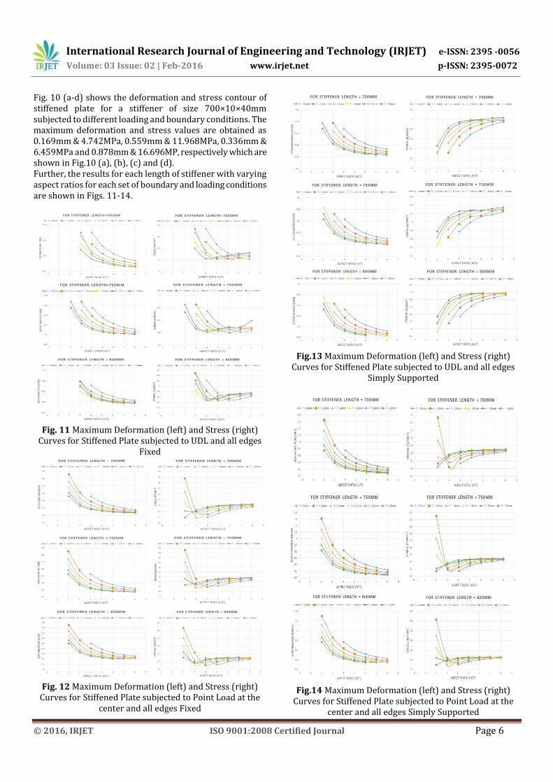
Fig. 10 (a-d) shows the deformation and stress contour of stiffened plate for a stiffener of size 700×10×40mm subjected to different loading and boundary conditions. The maximum deformation and stress values are obtained as 0.169mm & 4.742MPa, 0.559mm & 11.968MPa, 0.336mm & 6.459MPa and 0.878mm & 16.696MP, respectively which are shown in Fig.10 (a), (b), (c) and (d). Further, the results for each length of stiffener with varying aspect ratios for each set of boundary and loading conditions are shown in Figs. 11-14.
Fig. 11 Maximum Deformation (left) and Stress (right)
Curves for Stiffened Plate subjected to UDL and all edges Fixed
Fig. 12 Maximum Deformation (left) and Stress (right)
Curves for Stiffened Plate subjected to Point Load at the center and all edges Fixed
Fig.13 Maximum Deformation (left) and Stress (right)
Curves for Stiffened Plate subjected to UDL and all edges Simply Supported
Fig.14 Maximum Deformation (left) and Stress (right)
Curves for Stiffened Plate subjected to Point Load at the center and all edges Simply Supported

International Research Journal of Engineering and Technology (IRJET) e-ISSN: 2395 -0056
Volume: 03 Issue: 02 | Feb-2016 www.irjet.net p-ISSN: 2395-0072
© 2016, IRJET ISO 9001:2008 Certified Journal Page 7
It is observed that the pattern of deformation curve is same for both the type of stiffened plate and also observed that the maximum stress decreases with the increase in aspect ratio for both the cases but in Fig. 13 one exceptional behavior is noticed where the maximum stress in the plate increases with the increase in aspect ratio for the stiffener having length of 750mm.
4. CONCLUSIONS This paper presents the behavior of stiffened plate under transverse loading conditions. Based on observations the following concluding remarks are made. 1. The height of stiffener shall not be increased beyond six times of thickness as it gives very less improvement in deformation. Since, the maximum deformations in all scenario of varying thickness & aspect ratio tend to converge towards a minimum value and beyond the aspect ratio of 6 the results are very close to each other. 2. The stiffener having lesser thickness gives almost equal deformation with that of greater thickness stiffener having more or less equal volume of material. 3. The stiffener having lesser height and greater thickness can be used at the places where there is limitation of space otherwise the stiffener having greater height and lesser thickness may always be recommended. 4. The maximum deformation of composite plate is about 1.5 to 2.5 times than that of isotropic plate. 5. The maximum stress in composite plate is on lower side than that of isotropic plate. The aim of this study is to highlight the effectiveness of stiffeners in the plate. The results presented herein are for deformation and stresses which can be useful for fixing the geometry of stiffener in the plate. The cost effectiveness of the stiffened plate may be studied further for achieving the economy in the construction of real life structures having stiffened plates.
REFERENCES
[1] D. Venugopal Rao, A. H. Sheikh and M. Mukhopadhyay, “A finite element large displacement analysis of stiffened plates,” Computers & Structures, Vol. 47, No.6, 1993, pp. 987-993.
[2] M. Mukhopadhyay, “Stiffened plates in bending,” Computers & Structures Vol. 500, No. 4, 1994, pp. 541-548.
[3] Osama K. Bedair, “Influence of stiffener location on the stability of stiffened plates under compression and in-plane bending,” Int. J. Mech. Sci. Vol. 39, No. 1, 1997, pp. 33-49.
[4] W. Akl, A. El-Sabbagh and A. Baz, “Optimization of the static and dynamic characteristics of plates with isogrid stiffeners,” Finite Elements in Analysis and Design, Vol.44, 2008, pp. 513 – 523.
[5] Li Li and Ren Xiaohui, “Stiffened plate bending analysis in terms of refined triangular laminated plate element,” Composite Structures, Vol. 92, 2010, pp. 2936–2945.
[6] Yucheng Liu and Qingkui Wang, “Computational study of strengthening effects of stiffeners on regular and arbitrarily stiffened plates,” Thin-Walled Structures, Vol. 59, 2012, pp. 78–86.
[7] Yucheng Liu and Qingkui Wang, “Strengthening effects of stiffeners on arbitrarily stiffened plates and regularly stiffened plates subject to biaxial stress,” Thin-Walled Structures, Vol. 68, 2013, pp. 85–91.
[8] T. Nguyen-Thoi, T. Bui-Xuan, P. Phung-Van, H. Nguyen-Xuan and P. Ngo-Thanh, “Static, free vibration and buckling analyses of stiffened plates by CS-FEM-DSG3 using triangular elements,” Computers and Structures, Vol. 125, 2013, pp. 100–113
[9] Ahmed and Rameez, “Study of strengthening effects of stiffeners on regular and arbitrarily stiffened plates (eigen buckling analysis) using ansys,” International conference on mechanical and industrial engineering, 2014.
[10] D. K. Singh, S. K. Duggal and P. Pal, “Analysis of stiffened plates using FEM – a parametric study,” International research journal of engineering and technology, Vol. 02, July 2015.
[11] Timoshenko and Woinowsky-Krieger, “Theory of plates and shells,” McGraw–Hill New York, 1959.
BIOGRAPHIES
Mr. R. R. Singh is M.Tech Scholar in the Department of Civil Engineering at Motilal Nehru National Institute of Technology, Allahabad, India.
Dr. P. Pal is currently Assistant Professor in the Department of Civil Engineering at Motilal Nehru National Institute of Technology, Allahabad, India.