buckling of perforated and unperforated stiffened plate filebuckling of perforated and unperforated...
TRANSCRIPT
Journal of Babylon University/Engineering Sciences/ No.(2)/ Vol.(25): 2017
451
Buckling of Perforated and Unperforated Stiffened Plate
Qasim H. Bader Al-Amar Mohammed S. Hassan AL-Araji Mechanical Engineering / University of Babylon
[email protected] [email protected]
Abstract This paperfocuses on the studied the structural instability caused by perforated andunperforated
stiffened plate having all round simply supported boundary conditions subjected to in-plane uniaxial compressive load and also to the unperforated and perforated plateare reinforced with two stiffeners in (longitudinal, transverse and combined)directions. The aspect ratio, area ratios, and number and direction of stiffeners are the parameters considered.The analytical solutions are carry out by energy method. A finite element analysis is carry out by software Ansys. Results show that the presence of a three central circular perforations reasondecreases in buckling load factor of plate and the stiffeners can be used to reduce this decreasing. It is also concluded effect of transverse stiffeners which is less than that of longitudinal stiffeners for both unperforated and perforated plate.Increase the cutout ratio to η=0.15 at δ=0.125, β=1 will lead to decrease the K (10, 21 and 10.6)% for SSSS2L3, SSSS2T3 and SSSS4C3 respectively at when compare with SSSS2L0, SSSS2T0 and SSSS4C0.The economical design of structuresislikely by presenting stiffeners of optimum size.
Keywords: perforated and un perforated plate, buckling analysis, bucking load factor, stiffened and unstiffened plates.
الخالصة
الشرط الحدودیة ذات المساند والغیر مثقبة والتي تمتلكمقواة المثقبة عدم االستقراریة الهیكلیة للصفائح ال دراسةهذا البحث ركز على
من جمیع الجهات والمعرضة لحمل ضغط محوري وكذلك الصفیح المثقبة والغیر مثقبة معززة باثنان من المقویات في االتجاة البسیطة
عدد قواة الى الصفیحةمساحة الم نسبة، نسبة طول الصفیحة الى العرضالمتغیرات التي تم اعتبارها هي ). العرضي والجامع. الطولي(
النتائج اظهرت وجود ثالثة ثقوب .)Ansys(الحل العددي انجز بواسطة برنامج ) نظریة الطاقة(الحل التحلیلي انجز بواسطة .المقواة واتجاه
ان تاثیر وكذلك استنتج تعویض ذلك االنخفاض بواسطة استخدام المقویاتدائریة في مركزالصفیحة یسبب انخفاض معامل االنبعاج ویمكن
سوف η=0.15كما ان زیادة نسبة القطع الى .المقویات العرضیة اقل فائدة من المقویات الطولیة لكل من الصفائح المثقبة والغبر مثقبة
ان .β=1و δ=0.025مع المقواة الغیر مثقبة عند تهاعند مقارنلصفائح المثقبة المقواة %(and 2 13 ,2.1)حوالي K یؤدي الى اخفاض
. التصمیم االقتصادي للهیاكل محتمل بواسطة تقدیم امثل حجم للمقویات
.الصفائح المقواة والغیر مقواة، معامل االنبعاج، تحلیل االنبعاج، الصفائح المثقب والغیر مثقبة: المفتاحیه الكلمات
Nomenclature β = Aspect ratio δ = Area ratio η= Cutout ratio SSSS00 = unperforated plate with Simply support BC
SSSS2L0, SSSS2T0 and SSSS4C0 = unperforated plate with two( longitudinal, transverse and combined) stiffeners, with Simply support BC.
SSSS2L3, SSS2T3 and SSSS4C3 = perforated plate with two( longitudinal, transverse and combined) stiffeners ,with Simply support BC.
1.Introduction plates widely uses in civil and mechanical industries . Generally, in plate cutouts
are provided to decrease the self-weight, to provide service area and even aesthetics. When these plates are subject to loading, the presence of cutouts will effect on the redistribution of the stresses, consequently there will be effect in the buckling and
Journal of Babylon University/Engineering Sciences/ No.(2)/ Vol.(25): 2017
452
ultimate strength of the plate. The (shape ,number and location) of a cutout, the type of loading, different boundary conditions, thickness ratios of the plate and, these parameters effect on the mechanical behavior of plates(Jayashankarbabu, 2014). On the other hand, though the cutouts are provided to accomplishes certain structural advantages, it is worth to investigate here on the effect of hole in the stability of the plate in the form of buckling. If the perforated plate used then a design solution must use to increase the stability of perforated plate, This always can be achieved by increase thickness of plate but the design will not be economical because of increasing in the weight of material used. It is possible to design an effectively strong and rigid plate element by keeping its thickness as small as possible and employ stiffener to increase the stiffens(Timoshenko, 1963).
The stability of stiffened plate under various compressive loadings and boundary conditions has been the subject and studied by:
(Srivastava & DATTA ,2006) focused on effects of cutouts on the stability of square stiffened plates, it was contained on the longitudinal stiffener with square cutouts and subject to in plane biaxial load with various boundary condition ,used finite element method to determine the buckling load coefficient and modes shapes with square cutouts and various edge conditions.The result was showed the buckling load factor decrease with increase cutout size for simply and simply clamp boundary condition edge and increase with increase cutout for clamp. (Cheng and Zhao 2010) investigated the effect of stiffener on the perforated plate. There four types of stiffener investigated were flat ,ring ,longitudinal and transverse. the square plate subject to uniaxial compression load. The results show presence the stiffener in the perforated plate lead to improve the buckling load.(Nildem,Taysi; 2010) studied the effect stiffeners locations on critical buckling load of stiffened plates, have used finite strip method to select the buckling load. The optimize design variable was obtained by Sequential Quadratic Programming algorithm. ( Jawad,2012) have used finite difference method for linear buckling analysis of thin plates subjected to in-plane patch load.(Jayashankarbabua and Karisiddappa; 2014) analyzed Stability of Square Plate with Concentric Cutout, employed isotropic plate with (rectangular, square and circular) cutout, subject to in plane uniaxial and biaxial compression load ,the study performed by finite element analysis in the ANSYS package for various boundary condition.( Anupama and Jayashankarbabu; 2014) studied the effect of stiffener on the buckling of unperforated and perforated plates ,the boundary condition is simply support and subject to uniaxial load and plate contained stiffener in longitudinal and transverse directions ,finite element analysis is carried out in the ansys package.The two longitudinal stiffeners on either side of the central circular perforation increase the buckling load factor of the perforated plate .(Shruthi and Jayashankarbabu ; 2014) introduced the Analysis of Isotropic Perforated Stiffened Plate and examined the stability of structure ,subject in plane uniaxial compression load and boundary condition is simply support and clamped ,and used circular and square perforated plate, finite element analysis is carried out in the ansys package.Theresults showed that the presence of a central hole causes deceasing in buckling load factor and stiffeners can be employed to compensate this reduction. (Ashutosh kumar, et.al.,2015) studiedbuckling analysis of rectangular stiffened plate. These structures are subjected to uniaxial load with simply support boundary condition. Analytical solution is produced by Equilibrium method.
Journal of Babylon University/Engineering Sciences/ No.(2)/ Vol.(25): 2017
Finite element analysis is produceload and corresponding buckling mode for stiffened and unstiffened plate.showed presencesimilar pattern with different modes for both case focused essentially on the linear buckling analysis of isotropic stiffened plate exposed to uniaxial load with simply support produced by energy method. Finite element analysis is produced by select buckling load factor(aspect ratio, area ratio, andcutout ratio) factor.The material of the plate is assumed to modulus E=210000N/mm2 and Poisson’s ratio
2. Finite Element DiscretizationIn latest years, finite element is widely used to analyze the structure. This
the more powerful numerical technique, which producepragmatic types of structures. The use of the computational tools design. More accurate results may be achieved in order to reaching safe adesign.In the present workelement type (shellsuitable for the analysis of thin structure, the element has 8freedom at each node translations and rotations in (x,y,z).
3. Buckling Analysis Of Energy method can be used for buckling
the strain energy and work done of structureofcritical buckling stress andstiffened plate consists number of longitudinal stiffener that dividing the width of plate into parts the boundary conditions is simply support in all edges and subject touniaxial compression loads as illustrated in the
Fig(2):boundary condition of stiffened plate
Journal of Babylon University/Engineering Sciences/ No.(2)/ Vol.(25): 2017
453
Finite element analysis is produced by Nastran program to select critical buckling load and corresponding buckling mode for stiffened and unstiffened plate.
presencesimilar pattern with different modes for both case .focused essentially on the linear buckling analysis of isotropic stiffened plate exposed to
simply support boundary condition (B.C). Analytical solution is method. Finite element analysis is produced by factor for stiffened plate, in addition to the parameters such as
aspect ratio, area ratio, andcutout ratio) are considered, its effect on the buckling loThe material of the plate is assumed to be homogeneous, isotropic with young’s
N/mm2 and Poisson’s ratio ν= 0.3.
Finite Element Discretization In latest years, finite element is widely used to analyze the structure. This
the more powerful numerical technique, which produces an approximate solution to most pragmatic types of structures. The use of the computational tools has become common in design. More accurate results may be achieved in order to reaching safe a
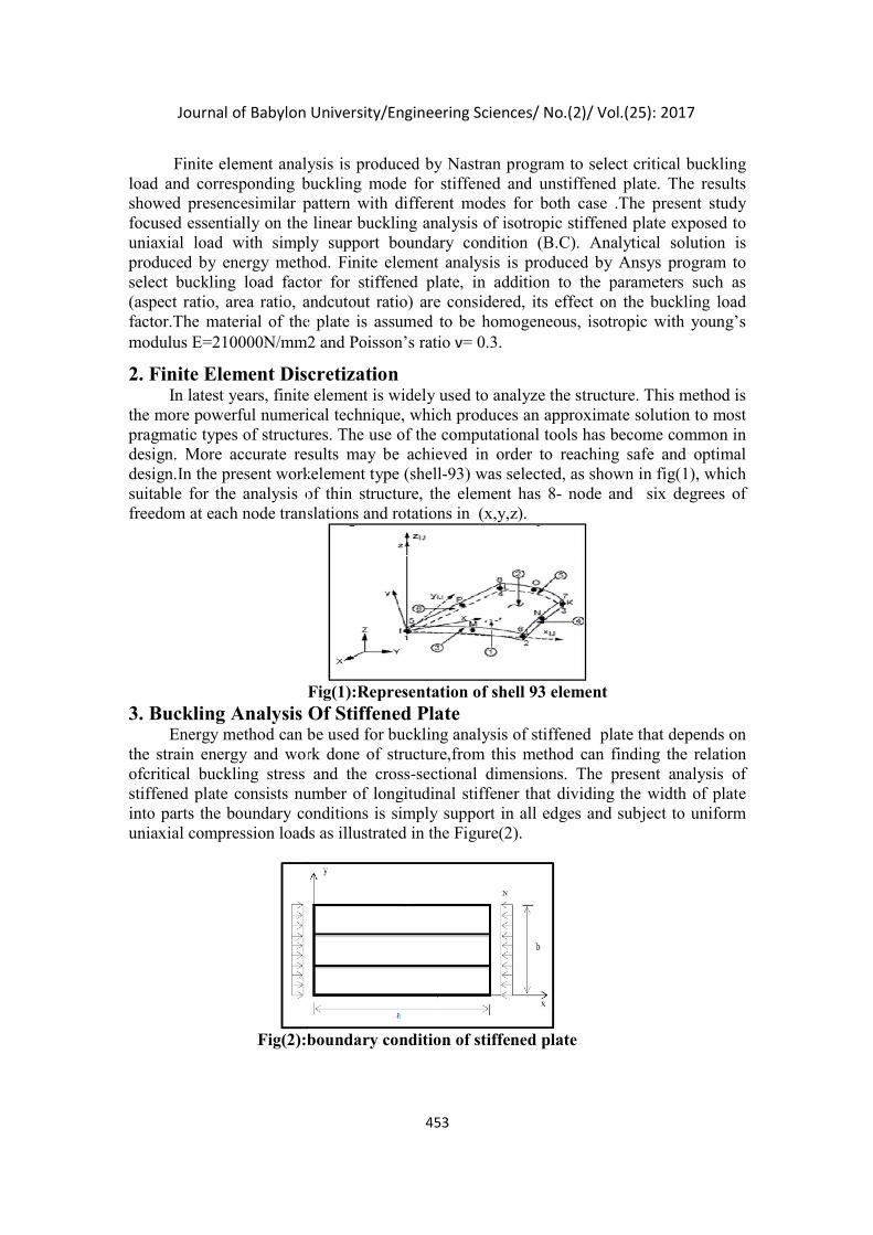
In the present workelement type (shell-93) was selected, as shown in fig(1),suitable for the analysis of thin structure, the element has 8- node and six degrees of freedom at each node translations and rotations in (x,y,z).
Fig(1):Representation of shell 93 element
. Buckling Analysis Of Stiffened Plate can be used for buckling analysis of stiffened plate
ergy and work done of structure,from this method can finding the relation critical buckling stress and the cross-sectional dimensions. The present analysis of
number of longitudinal stiffener that dividing the width of plate into parts the boundary conditions is simply support in all edges and subject touniaxial compression loads as illustrated in the Figure(2).
boundary condition of stiffened plate
Journal of Babylon University/Engineering Sciences/ No.(2)/ Vol.(25): 2017
by Nastran program to select critical buckling load and corresponding buckling mode for stiffened and unstiffened plate. The results
.The present study focused essentially on the linear buckling analysis of isotropic stiffened plate exposed to
Analytical solution is method. Finite element analysis is produced by Ansys program to
, in addition to the parameters such as its effect on the buckling load
be homogeneous, isotropic with young’s
In latest years, finite element is widely used to analyze the structure. This method is an approximate solution to most
become common in design. More accurate results may be achieved in order to reaching safe and optimal
as shown in fig(1), which node and six degrees of
plate that depends on ,from this method can finding the relation
he present analysis of number of longitudinal stiffener that dividing the width of plate
into parts the boundary conditions is simply support in all edges and subject to uniform
Journal of Babylon University/Engineering Sciences/ No.(2)/ Vol.(25): 2017
454
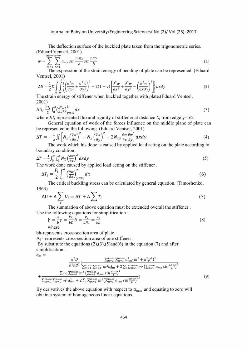
The deflection surface of the buckled plate taken from the trigonometric series. (Eduard Ventsel, 2001)
� = � � ���
���
���
���
���
������
����
���
�(1)
The expression of the strain energy of bending of plate can be represented. (Eduard Ventsel, 2001)
∆� =1
2� � � ��
���
���+
���
����
�
− 2(1 − �)����
���+
���
���− �
���
�����
�
�� ����(2)
�
�
�
�
The strain energy of stiffener when buckled together with plate.(Eduard Ventsel, 2001)
∆�����
�∫ ����
��������
���
�
� (3)
where��� represented flexural rigidity of stiffener at distance ��from edge y=b/2 General equation of work of the forces influence on the middle plane of plate can
be represented in the following. (Eduard Ventsel, 2001)
∆� = −�
�∬ ��� �
��
���
�
+ �� ���
���
�
+ 2�����
��
��
��� ���� (4)
The work which his done is caused by applied load acting on the plate according to boundary condition .
∆� =�
�∫ ∫ �� �
��
���
�����
�
�
�
� (5)
The work done caused by applied load acting on the stiffener .
∆�� =��
2� �
��
���
����
��
�
��(6)
The critical buckling stress can be calculated by general equation. (Timoshenko, 1963)
∆U + ∆ � ��
�
= ∆� + ∆ � ��
�
(7)
The summation of above equation must be extended overall the stiffener . Use the following equations for simplification .
β =�
�� =
���
��� =
��
���=
��
�� (8)
where bh-represents cross-section area of plate. Ai - represents cross-section area of one stiffener . By substitute the equations (2),(3),(5)and(6) in the equation (7) and after simplification . ��� =
���
��ℎ��[
∑ ∑ ���� (�� + ����)����
���������
∑ ∑ ���������
��������� + 2 ∑ ∑ ���∑ ��� sin ����
�
������ �
��������
+∑ ��� ∑ �����
��� �∑ ��� ��� �����
������ �
�
∑ ∑ ���������
��������� + 2 ∑ ∑ ���∑ ��� ��� ����
������� �
��������
](9)
By derivatives the above equation with respect to ��� and equating to zero will obtain a system of homogeneous linear equations .
Journal of Babylon University/Engineering Sciences/ No.(2)/ Vol.(25): 2017
455
���
��ℎ����(�� + ����)� + 2 � ��
�
�������
��� � ��� ���
����
�
���
���
�
−����� ������ + 2 � �� sin����
��� � ���
���
���
sin����
��
� = 0(10)
Where ���-can be found by equating the determining factor of this equation to zero.We can assume the stiffened plate buckles into one half -wave , therefore we take m=1 and substitute in equation (10), after simplification.
���
��ℎ��[��(1 + ��)� + 2�(�� − �� + �� −∙∙∙)] − ���[�� + 2�(�� − �� + �� −∙∙∙)] = 0(11)
when the plate stiffened by two equal longitudinal stiffener dividing the width of plate into three equal parts. assume the buckling form is symmetrical about the middle axis at(� = � 2⁄ ). The first approximation of critical buckling stress obtaining after substitute the �� = � 3⁄ ,and � = 1 , in the equation (10) and after simplification the equation we obtained .
��� =���
��ℎ
(1 + ��)� + 3�
��(1 + 3�)(12)
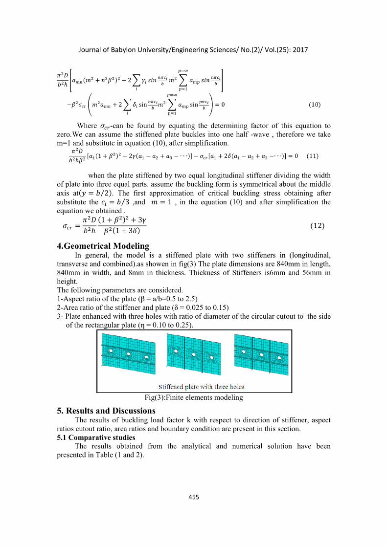
4.Geometrical Modeling In general, the model is a stiffened plate with two stiffeners in (longitudinal,
transverse and combined).as showen in fig(3) The plate dimensions are 840mm in length, 840mm in width, and 8mm in thickness. Thickness of Stiffeners is6mm and 56mm in height. The following parameters are considered. 1-Aspect ratio of the plate (β = a/b=0.5 to 2.5) 2-Area ratio of the stiffener and plate (δ = 0.025 to 0.15) 3- Plate enhanced with three holes with ratio of diameter of the circular cutout to the side
of the rectangular plate (η = 0.10 to 0.25).
Fig(3):Finite elements modeling
5. Results and Discussions The results of buckling load factor k with respect to direction of stiffener, aspect
ratios cutout ratio, area ratios and boundary condition are present in this section. 5.1 Comparative studies
The results obtained from the analytical and numerical solution have been presented in Table (1 and 2).
Journal of Babylon University/Engineering Sciences/ No.(2)/ Vol.(25): 2017
456
Table 1 Comparison of buckling load factor (k) for different Aspect ratio for SSSS isotropic
unperforated plate with two longitudinal stiffener subjected to in-plane uniaxial compression loading. (δ=0.05;� = 8.9;Ci=b/3).
β K-analytical K –numerical error 100%
1 26.74 25.42 4.93
1.5 14.42 14.86 3.051
2 11.25 11.91 5.86
2.5 11.06 11.83 6.96
3 12.25 13.2 7.75
Table 2 Comparison of buckling load factor (k) for different Aspect ratio for SSSS isotropic
unperforated plate with two transverse stiffener subjected to inplane uniaxial compression loading. (δ=0.05;γ-take from table of (Timoshenko,1963).
Β K-analytical K –numerical error 100%
0.9 9.26169 8.415916 9.131962
1 6.379901 6.250944 2.021306
1.2 5.004415 5.133663 -2.58267
1.414 4.500145 4.491432 0.193623
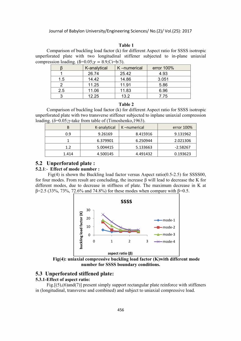
5.2 Unperforated plate : 5.2.1:- Effect of mode number :
Fig(4) is shown the Buckling load factor versus Aspect ratio(0.5-2.5) for SSSS00, for four modes. From result are concluding, the increase β will lead to decrease the K for different modes, due to decrease in stiffness of plate. The maximum decrease in K at β=2.5 (33%, 73%, 72.6% and 74.8%) for these modes when compare with β=0.5.
Fig(4): uniaxial compressive buckling load factor (K)with different mode
number for SSSS boundary conditions.
5.3 Unperforated stiffened plate: 5.3.1-Effect of aspect ratio:
Fig.[(5),(6)and(7)] present simply support rectangular plate reinforce with stiffeners in (longitudinal, transverse and combined) and subject to uniaxial compressive load.
0
10
20
30
0 1 2 3
bu
cklin
g lo
ad f
acto
r (K
)
aspect ratio (β)
ssss
mode-1
mode-2
mode-3
mode-4
Journal of Babylon University/Engineering Sciences/ No.(2)/ Vol.(25): 2017
457
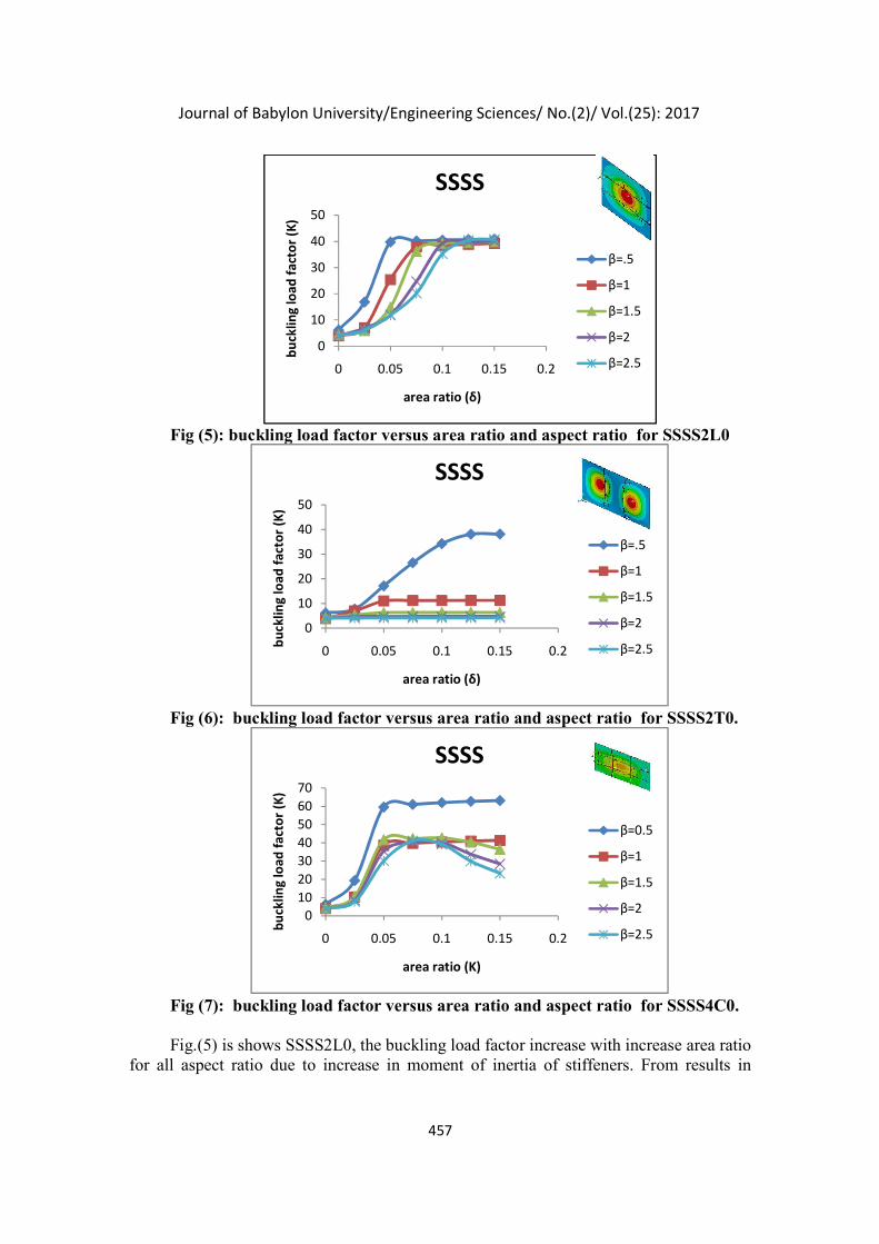
Fig (5): buckling load factor versus area ratio and aspect ratio for SSSS2L0
Fig (6): buckling load factor versus area ratio and aspect ratio for SSSS2T0.
Fig (7): buckling load factor versus area ratio and aspect ratio for SSSS4C0. Fig.(5) is shows SSSS2L0, the buckling load factor increase with increase area ratio
for all aspect ratio due to increase in moment of inertia of stiffeners. From results in
0
10
20
30
40
50
0 0.05 0.1 0.15 0.2
bu
cklin
g lo
ad f
acto
r (K
)
area ratio (δ)
SSSS
β=.5
β=1
β=1.5
β=2
β=2.5
0
10
20
30
40
50
0 0.05 0.1 0.15 0.2
bu
cklin
g lo
ad f
acto
r (K
)
area ratio (δ)
SSSS
β=.5
β=1
β=1.5
β=2
β=2.5
0
10
20
30
40
50
60
70
0 0.05 0.1 0.15 0.2
bu
cklin
g lo
ad f
acto
r (K
)
area ratio (K)
SSSS
β=0.5
β=1
β=1.5
β=2
β=2.5
Journal of Babylon University/Engineering Sciences/ No.(2)/ Vol.(25): 2017
458
fig.(5) conclude the SSSS2L0 gives best increasing in stiffness that leads to increase buckling load factor. For β=0.5 the optimum increase in k=5.49, at δ=0.05, for β=(1,1.5) the optimum increase in k=(8.6, 7.4)respectively at δ=0.075, for β=(2,2.5) the optimum increase in k=(8.9, 7.6) respectively at δ=0.1 when compare with SSSS00.
Fig.(6) is shows SSS2T0 plate. From results are conclude the behavior the stiffened plate at β=0.5 varies from β>0.5, for β=0.5 the optimum value of k at δ=0.125, for β>1 the optimum value of k at δ=0.05, increase in k very small after δ=0.05. Therefore small increase in stiffness insufficient to access for local buckling modes, because of location of stiffeners ineffective
Fig.(7) is shown SSSS4C0 plate. From results are conclude the value of K increase with increase δ due to increase in moment of inertia of stiffeners. For β=0.5 the optimum increase in K=8.6 times, at δ=0.05 when compare with SSSS00. For β>0.5 the optimum increase in K about(6.34 to 9)times at δ limited between (0.05-0.075) when compare with SSSS00.when β increase the influence of δ become small for this rang of δ. In SSSS4C0 consider benefit for provides high stiffness can be obtaining local buckling modes. From results in fig.[(5), (6) and (7)] will conclude, for β≥1 the maximum increase in buckling load factor(K) for SSSS4C0 more than SSSS2L0 and SSSS2T0, use the SSSS2T0 is ineffectual because of small increase in stiffness of structure.
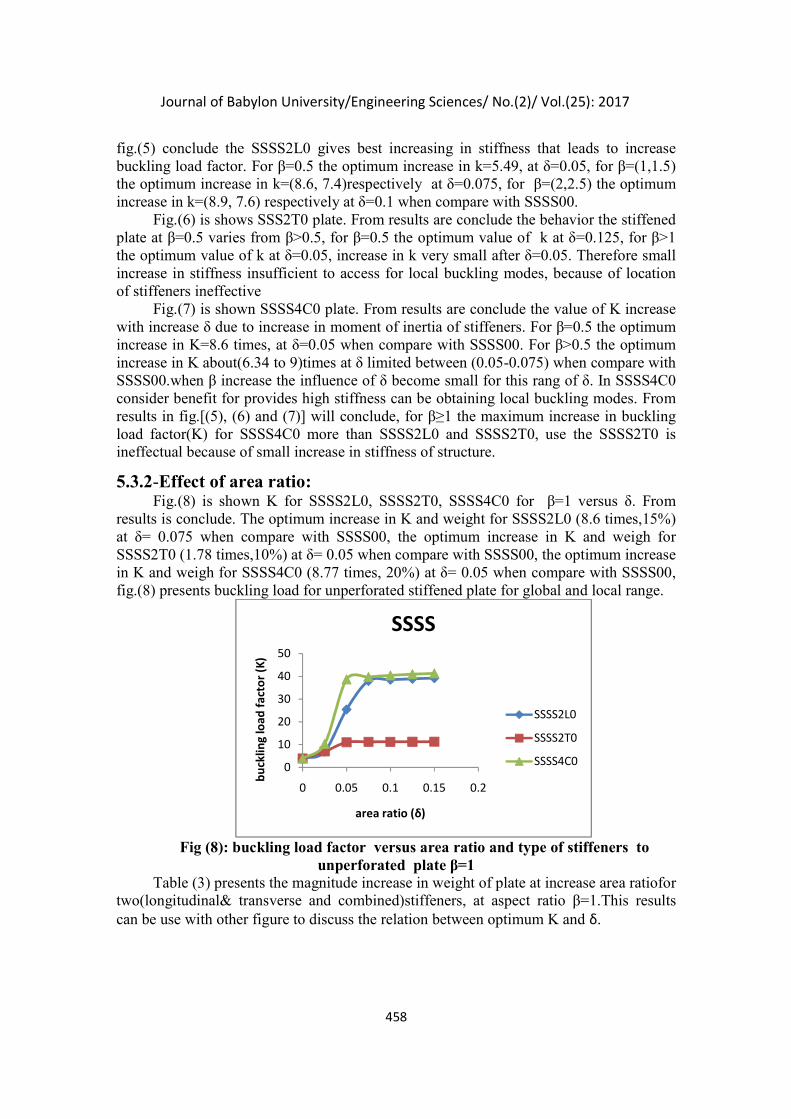
5.3.2-Effect of area ratio: Fig.(8) is shown K for SSSS2L0, SSSS2T0, SSSS4C0 for β=1 versus δ. From
results is conclude. The optimum increase in K and weight for SSSS2L0 (8.6 times,15%) at δ= 0.075 when compare with SSSS00, the optimum increase in K and weigh for SSSS2T0 (1.78 times,10%) at δ= 0.05 when compare with SSSS00, the optimum increase in K and weigh for SSSS4C0 (8.77 times, 20%) at δ= 0.05 when compare with SSSS00, fig.(8) presents buckling load for unperforated stiffened plate for global and local range.
Fig (8): buckling load factor versus area ratio and type of stiffeners to
unperforated plate β=1 Table (3) presents the magnitude increase in weight of plate at increase area ratiofor
two(longitudinal& transverse and combined)stiffeners, at aspect ratio β=1.This results can be use with other figure to discuss the relation between optimum K and δ.
0
10
20
30
40
50
0 0.05 0.1 0.15 0.2
bu
cklin
g lo
ad f
acto
r (K
)
area ratio (δ)
SSSS
SSSS2L0
SSSS2T0
SSSS4C0
Journal of Babylon University/Engineering Sciences/ No.(2)/ Vol.(25): 2017
459
area ratio total increase in weight
δ SSSS2L0% SSSS2T0 % SSSS4C0 %
0.025 5 5 10
0.05 10 10 20
0.075 15 15 30
0.1 20 20 40
Table (3): area ratio versus increase in weight stiffener type at β=1.
5.4.Stiffened plate perforated with three hole 5.4.1-Effect of area ratio:
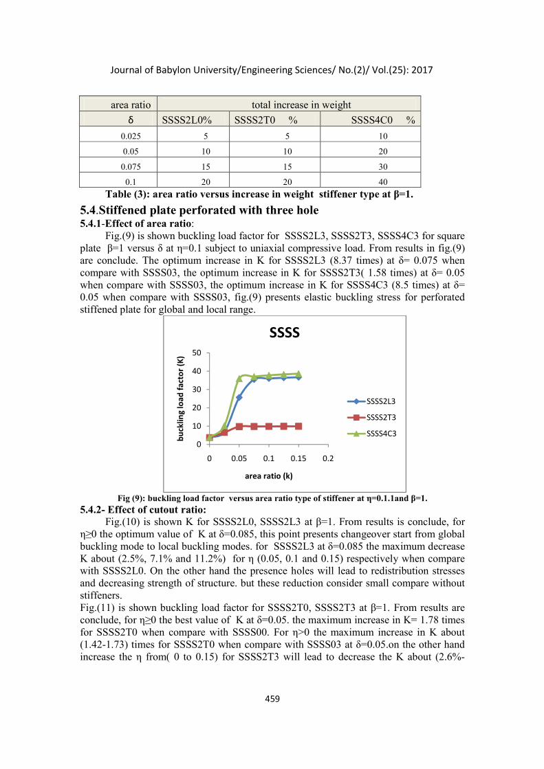
Fig.(9) is shown buckling load factor for SSSS2L3, SSSS2T3, SSSS4C3 for square plate β=1 versus δ at η=0.1 subject to uniaxial compressive load. From results in fig.(9) are conclude. The optimum increase in K for SSSS2L3 (8.37 times) at δ= 0.075 when compare with SSSS03, the optimum increase in K for SSSS2T3( 1.58 times) at δ= 0.05 when compare with SSSS03, the optimum increase in K for SSSS4C3 (8.5 times) at δ= 0.05 when compare with SSSS03, fig.(9) presents elastic buckling stress for perforated stiffened plate for global and local range.
Fig (9): buckling load factor versus area ratio type of stiffener at η=0.1.1and β=1.
5.4.2- Effect of cutout ratio: Fig.(10) is shown K for SSSS2L0, SSSS2L3 at β=1. From results is conclude, for
η≥0 the optimum value of K at δ=0.085, this point presents changeover start from global buckling mode to local buckling modes. for SSSS2L3 at δ=0.085 the maximum decrease K about (2.5%, 7.1% and 11.2%) for η (0.05, 0.1 and 0.15) respectively when compare with SSSS2L0. On the other hand the presence holes will lead to redistribution stresses and decreasing strength of structure. but these reduction consider small compare without stiffeners. Fig.(11) is shown buckling load factor for SSSS2T0, SSSS2T3 at β=1. From results are conclude, for η≥0 the best value of K at δ=0.05. the maximum increase in K= 1.78 times for SSSS2T0 when compare with SSSS00. For η>0 the maximum increase in K about (1.42-1.73) times for SSSS2T0 when compare with SSSS03 at δ=0.05.on the other hand increase the η from( 0 to 0.15) for SSSS2T3 will lead to decrease the K about (2.6%-
0
10
20
30
40
50
0 0.05 0.1 0.15 0.2
bu
cklin
g lo
ad f
acto
r (K
)
area ratio (k)
SSSS
SSSS2L3
SSSS2T3
SSSS4C3
Journal of Babylon University/Engineering Sciences/ No.(2)/ Vol.(25): 2017
460
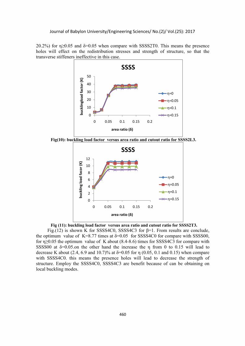
20.2%) for η≥0.05 and δ=0.05 when compare with SSSS2T0. This means the presence holes will effect on the redistribution stresses and strength of structure, so that the transverse stiffeners ineffective in this case.
Fig(10): buckling load factor versus area ratio and cutout ratio for SSSS2L3.
Fig (11): buckling load factor versus area ratio and cutout ratio for SSSS2T3. Fig.(12) is shown K for SSSS4C0, SSSS4C3 for β=1. From results are conclude,
the optimum value of K=8.77 times at δ=0.05 for SSSS4C0 for compare with SSSS00, for η≥0.05 the optimum value of K about (8.4-8.6) times for SSSS4C3 for compare with SSSS00 at δ=0.05.on the other hand the increase the η from 0 to 0.15 will lead to decrease K about (2.4, 6.9 and 10.7)% at δ=0.05 for η (0.05, 0.1 and 0.15) when compare with SSSS4C0. this means the presence holes will lead to decrease the strength of structure. Employ the SSSS4C0, SSSS4C3 are benefit because of can be obtaining on local buckling modes.
0
10
20
30
40
50
0 0.05 0.1 0.15 0.2
bu
cklin
glo
ad f
acto
r (K
)
area ratio (δ)
SSSS
η=0
η=0.05
η=0.1
η=0.15
0
2
4
6
8
10
12
0 0.05 0.1 0.15 0.2
bu
cklin
g lo
ad f
aco
r (K
)
area ratio (δ)
SSSS
η=0
η=0.05
η=0.1
η=0.15
Journal of Babylon University/Engineering Sciences/ No.(2)/ Vol.(25): 2017
461
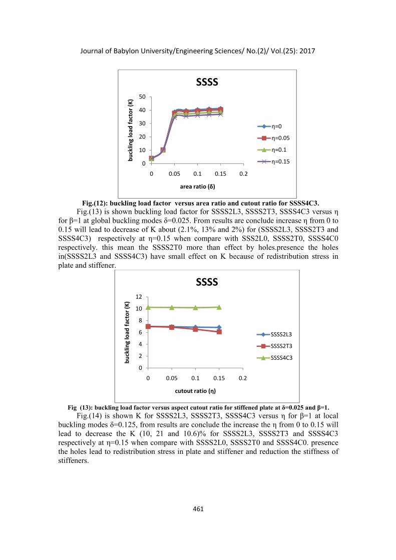
Fig.(12): buckling load factor versus area ratio and cutout ratio for SSSS4C3. Fig.(13) is shown buckling load factor for SSSS2L3, SSSS2T3, SSSS4C3 versus η
for β=1 at global buckling modes δ=0.025. From results are conclude increase η from 0 to 0.15 will lead to decrease of K about (2.1%, 13% and 2%) for (SSSS2L3, SSSS2T3 and SSSS4C3) respectively at η=0.15 when compare with SSS2L0, SSSS2T0, SSSS4C0 respectively. this mean the SSSS2T0 more than effect by holes.presence the holes in(SSSS2L3 and SSSS4C3) have small effect on K because of redistribution stress in plate and stiffener.
Fig (13): buckling load factor versus aspect cutout ratio for stiffened plate at δ=0.025 and β=1.
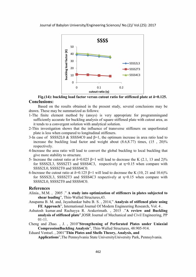
Fig.(14) is shown K for SSSS2L3, SSSS2T3, SSSS4C3 versus η for β=1 at local buckling modes δ=0.125, from results are conclude the increase the η from 0 to 0.15 will lead to decrease the K (10, 21 and 10.6)% for SSSS2L3, SSSS2T3 and SSSS4C3 respectively at η=0.15 when compare with SSSS2L0, SSSS2T0 and SSSS4C0. presence the holes lead to redistribution stress in plate and stiffener and reduction the stiffness of stiffeners.
0
10
20
30
40
50
0 0.05 0.1 0.15 0.2
bu
cklin
g lo
ad f
acto
r (K
)
area ratio (δ)
SSSS
η=0
η=0.05
η=0.1
η=0.15
0
2
4
6
8
10
12
0 0.05 0.1 0.15 0.2
bu
cklin
g lo
ad f
acto
r (K
)
cutout ratio (η)
SSSS
SSSS2L3
SSSS2T3
SSSS4C3
Journal of Babylon University/Engineering Sciences/ No.(2)/ Vol.(25): 2017
462
Fig.(14): buckling load factor versus cutout ratio for stiffened plate at δ=0.125.
Conclusions: Based on the results obtained in the present study, several conclusions may be
drawn. These may be summarized as follows: 1-The finite element method by (ansys) is very appropriate for programmingand
sufficiently accurate for buckling analysis of square stiffened plate with cutout area, as it tends to a convergent solution with analytical solution.
2-This investigation shows that the influence of transverse stiffeners on unperforated plate is less when compared to longitudinal stiffeners.
3-In case of SSSS2L0 & SSSS4C0 and β=1, the optimum increase in area ratio lead to increase the buckling load factor and weight about (8.6,8.77) times, (15 , 20)% respectively.
4-Increase the area ratio will lead to convert the global buckling to local buckling that give more stability to structure.
5- Increase the cutout ratio at δ=0.025 β=1 will lead to decrease the K (2.1, 13 and 2)% for SSSS2L3, SSSS2T3 and SSSS4C3, respectively at η=0.15 when compare with SSSS2L0, SSSS2T0 and SSSS4C0.
6-Increase the cutout ratio at δ=0.125 β=1 will lead to decrease the K (10, 21 and 10.6)% for SSSS2L3, SSSS2T3 and SSSS4C3 respectively at η=0.15 when compare with SSSS2L0, SSSS2T0 and SSSS4C0.
References Alinia., M.M. , 2005 .” A study into optimization of stiffeners in plates subjected to
shear loading”, Thin-Walled Structures,43. Anupama B. M. and, Jayashankar babu B. S. , 2014,” Analysis of stiffened plate using
FE Approach”, International Journal Of Modern Engineering Research, Vol. 4 . Ashutosh kumar.and Rachayya R. Arakerimath. , 2015 .”A review and Buckling
analysis of stiffened plate”,IOSR Journal of Mechanical and Civil Engineering, PP 01-11.
Cheng and Zhao. , J. , 2010”Strengthening of Perforated Plates under Uniaxial CompressionBuckling Analysis”, Thin-Walled Structures, 48:905-914.
Eduard Ventsel. , 2001”Thin Plates and Shells Theory, Analysis, and Applications”,The Pennsylvania State UniversityUniversity Park, Pennsylvania.
0
10
20
30
40
50
0 0.1 0.2
bu
cklin
g lo
ad f
acto
r (K
)
cutout ratio (η)
SSSS
SSSS2L3
SSSS2T3
SSSS4C3
Journal of Babylon University/Engineering Sciences/ No.(2)/ Vol.(25): 2017
463
Jawad T. Abodi., 2012,” elastic buckling of plates under in-plane patch loading using finite difference method”, Journal of Kerbala University, Vol. 10.
Jayashankarbabu, B. S. , Karisiddappa. , 2014.” Stability of Square Plate with Concentric Cutout”, International Journal of Civil, Environmental, Structural, Construction and Architectural Engineering, Vol.8.
Naseer Hamed Farhood., 2012” Numerical and Experimental Investigation of Plate Buckling Under in-Plane Loading”, Eng. & Tech. Journal, Vol.30.
Nildem Tayi. 2010,”Determination of thickness and stiffener locations for optimization of critical buckling load of stiffened plates”, Scientific Research and Essays Vol. 5(9).
Shanmugam and A. Tahmasebinejad. , 2011” Elastic Buckling of Uniaxially loaded skew Plates containing Openings”, Thin-Walled Structures, 49:1208-1216.
Shruthi H.G.and Jayashankarbabu B.S. 2014”Analysis of Isotropic Perforated Stiffened Plate Using FEM”,Int. Journal of Engineering Research and Applications,Vol. 4,.
Srivastava, A.K.L. , and P.K. Datta. , 2006” elastic stability of square stiffened plates with cutouts under biaxial loading”, Int. J. of Applied Mechanics and Engineering, vol.11, No.2, pp.421-433.
Stephen P. Timoshenko. and James M. Gere. , 1963” Theory of elastic stability”, international student edition.