bridge performance during the great east japan earthquake
TRANSCRIPT

BRIDGE PERFORMANCE DURING THE GREAT EAST JAPAN EARTHQUAKE OF MARCH 11, 2011
M. Lee Marsh, Ian G. Buckle, W. Phillip Yen, Shideh Dasti, David Frost, Eric Monzon (See Acknowledgements for author affiliations)
Abstract
On March 11, 2011 the Great East Japan Earthquake struck the northeast coastal areas of Japan. Numerous bridges were damaged by either ground shaking or tsunami. A reconnaissance team from the US visited 11 bridge sites in June, and this report summarizes the observations and preliminary conclusions of several of those bridges. Staff from the PWRI hosted the reconnaissance effort and provided valuable technical data, excellent logistics, and useful insight into behavior and bridge practice throughout the reconnaissance effort. Introduction
About 200 highway bridges and numerous rail bridges were damaged during the Great East Japan Earthquake of March 11, 2011, including span unseating, foundation scour, ruptured bearings, column shear failures and approach fill settlements. The causes of this damage can be broadly classified in two categories: ground shaking including ground failure (liquefaction), and tsunami inundation. Of these, the tsunami was responsible for about one-half of the number of damaged bridges.
A joint EERI/FHWA/GEER reconnaissance team visited the affected area from June 2 to June 6, 2011 and investigated 11 bridges: 2 had extensive bearing failures, 2 had column failures, 2 had combined bearing and column failures and 4 suffered tsunami-related damage (unseated spans, scour, loss of approach fill).
The location and names of ten of the eleven bridges visited by the reconnaissance team are shown in Figure 1. The eleventh bridge was the Arakawa Wangan Bridge across the Arakawa River in Tokyo. The performance of five of the eleven bridges is summarized in this report. A detailed description of all eleven bridges is given in FHWA, 2010. Bridge Damage Due to Ground Shaking
In general the amount of damage due to ground shaking was remarkably light considering peak ground accelerations in some locations exceeded 1.0 g, with
FIGURE 1 – BRIDGES INVESTIGATED BY EERI\FHWA\ GEER RECONNAISANCE TEAM (Graphic: L. Marsh)

short-period spectral accelerations in excess of 5g. The most likely explanation is that, most, if not all of the bridges on the national highway system had been seismically retrofitted over the last 10-15years (in response to the widespread damage to bridges in the 1995 Hyogoken-Nanbu (Kobe) Earthquake). Bridges damaged in this earthquake by ground shaking were generally older structures owned by city and local governments, where retrofit programs have not been as active due to a lack of funding. With one exception, new bridges performed very well regardless of ownership most probably due to the adoption of conservative capacity design principles in the JRA Design Specifications in the 1990s. The one exception was the failure of elastomeric bearings in a section of the Sendai-Tobu Viaduct as described below. Three bridges are described in this section. Sendai-Tobu Viaduct
The damage to this 4.4 km long, multi-span viaduct in north Sendai was largely confined to a 10-span section between Piers 52 and 62. Built in 2000, this section of the viaduct was being widened at the time of the earthquake. New on- and off-ramps were under construction between Piers 54 and 56 to connect Route 10 carried by the viaduct to Route 141 below. Span lengths and type between Piers 51 and 58 are shown in Table 1.
TABLE 1. SPAN DETAILS AND DISTRIBUTION OF FAILED STEEL STOPPERS AND ELASTOMERIC BEARINGS IN SENDAI-TOBU VIADUCT.
Span No.
Span (m)
Span Type
Pier No.
Pier Type
No. failed
(damaged)2 stoppers in main event 3/11/2011
No. ruptured
(damaged)2 bearings in main event 3/11/2011
No. failed
(damaged)2 stoppers in aftershock 3/11/2011
No. ruptured
(damaged)2 bearings in aftershock
4/7/2011
51 1-col. 0 0 0 0
52 39.0 8 I-girders
521 1-col. 0/6 0/8 0 0
53 71.0 4 box girders
53 1-col.. 5 0 0 0
54 72.0 4 box girders
54 2-col. 4(2) 1 0 0
55 72.0 5 box girders
55 2-col. (6) 0 0 0
56 71.0 3 box girders
561 2-col. 6/6 (1)/8 0 0
57 39.0 8 I-girders
57 1-col. 1(1) 0 3 0
58 39.0 8 I-girders
581 2-col. 4(2)/5 1/0 0 (2)/0
59 39.0 8 I-girders
59 2-col. (3) 0 0 0
TOTALS 37(14) 18(1) 3 (2)
Note 1. There are two lines of stoppers and bearings on Piers 52, 56, and 58. 2. Numbers in parentheses are numbers of stoppers and bearings damaged but not ruptured.

The superstructure comprises eight steel plate girders (I-girders) between Piers 50 and 52, three, four, or five steel box girders between Piers 52 and 56, and eight steel plate girders between Piers 56 and 63. Elastomeric bearings are used exclusively with external stoppers to restrain transverse movement at almost every pier. Piers 54, 55, 56, 58 , 59 and 60 had recently been converted from single steel box columns to two-column steel box frames to accommodate the new on- and off-ramps (Figure 2). The remaining piers (51, 52, 53 and 57) are single-column steel boxes (Figure 3).
The bridge suffered moderate-to-major damage during the earthquake but no span collapsed. This damage included the failure of 40 steel stoppers and 18 elastomeric bearings. Another 14 stoppers and 3 bearings were heavily damaged. In addition, girder stiffeners, gusset plates, and cross-frames were buckled or severely distorted. Locations of the failed and damaged stoppers and bearings, due to both the March 11 main shock and the April 7 aftershock, are given in Table 1.
The pattern of the bearing damage in Table 1 is particularly interesting. It is concentrated in regions of the viaduct where there is a significant change in lateral stiffness – from single-column hammerhead piers at Pier 57 to two-column frames at Piers 54, 55 and 56, for example. There is also a significant change in the in-plane stiffness of the superstructure in this section, from eight I-girders in Spans 52 and 57 to multiple single-cell box girders in Spans 53 to 56. This section of the viaduct is therefore very stiff (and particularly Spans 55 and 56) while sections to the north and south are comparatively flexible. When earthquake loads are applied, the difference in displacements at the two interfaces (Piers 52 and 56) generate high lateral forces in the stoppers at these two piers leading to their failure and the transfer of load to the bearings.
Inspection of the damage to the bearings showed that many had ruptured completely through the elastomer, as if in direct tension. Others showed damage to the internal shims which had been severely distorted (Figure 4). Typical dimensions of the bearings at Pier 56
FIGURE 2 – TWO-COLUMN FRAME, PIER 56 SENDAI-TOBU VIADUCT (Photo: E. Monzon)
FIGURE 3 – SINGLE COLUMN, PIER 57 SENDAI-TOBU VIADUCT (Photo: E. Monzon)

are 820 x 870 x 508 mm, with 8 x 33 mm layers of elastomer, 7 x 4.5 mm shims and 2 x 45 mm end plates. The masonry and sole plate connections were detailed to transfer both shear and axial forces (tension and compression) into the bearings.
It seems possible that the bearings failed due to the combination of two effects. First the high lateral forces in the steel stoppers at Piers 52 and 56 were probably not evenly distributed amongst the three effective stoppers. (Although there are six stoppers at each pier, only three are effective in any one direction at any point in time.) This uneven distribution arises because the gaps between the stoppers and the sole plates of the bearings are not exactly the same at each location and one stopper will generally engage before the others. Overloading of this stopper is very likely, leading to its failure, followed by the transfer of load to the other stoppers which then fail in turn. Once all the stoppers have failed the transfer of load to the bearings places them under very high shear strain.
The second effect is the generation of high tensile forces in the bearings at these same locations due to the difference in pier type. For example Pier 56 is a 2-column frame and Pier 57 is a single column hammerhead pier. Under lateral load the hammerhead rotates about a longitudinal axis twisting the superstructure about the same axis. But the pier cap in the 2-column frame at Pier 56 does not rotate in this manner and this frame resists the twisting of the superstructure. High tensile forces are developed in the bearings as a result.
The simultaneous occurrence of high tension and high shear in the bearings could have led their failure.
The shim damage seen in Figure 4 most likely occurred when a ruptured bearing
impacted a toppled stopper puncturing the cover rubber layers and distorting the edge of the shim plate. On the other hand, the expected failure mode of an elastomeric bearing is rupture within a rubber layer and not delamination at the shim plate. The clean surface of this plate in Figure 4 implies inadequate bond between the elastomer and shim during manufacture thus reducing the bearing’s capacity for combined tension and shear.
Other damage to the superstructure included buckled cross-frame members, gusset plates and stiffeners, possibly due to the abrupt change in load path where the transverse member changes from a partial height diaphragm to a full depth cross-frame. But a more likely scenario is that this damage is due to the failure of the bearings below the girders leading to differential ‘settlement’ of the cross-frames and corresponding distortion and distress. Yuriage Bridge
The Yuriage Bridge carries Route 10 over the Natori River near the Sendai airport. The area experienced tsunami run-up, but the wave passed under the bridge and the
FIGURE 4 – DAMAGED ELASTOMERIC BEARING FROM PIER 52, SENDAI-TOBU VIADUCT (Photo: E. Monzon)

superstructure was not impacted. The bridge was built in 1974 and is comprised of ten spans with an overall length 542 m. The three main spans, located between Piers 2 and 5, are cast-in-place concrete box-girders and the center of these three spans comprises two balanced cantilevers meeting at mid span (Figure 5). The approach spans are prestressed concrete I-girders, simply supported on steel bearings at the pier caps, founded on wall piers with caisson-type foundations.
Pier 1 was damaged during the 1978 Miyagi-Oki Earthquake and was repaired with a concrete jacket. No widening or other seismic retrofits have been made since that time.
Complete bearing failures occurred at Piers 2 and 5, at the transition between the approach spans and main spans. These failures are attributed to permanent pier movement possibly caused by liquefaction. Evidence of extensive liquefaction was found under the approach spans and in some cases 30 cm of ground settlement was observed adjacent to one of the piers under the south approach. Since Piers 2 and 5 are close to the river, lateral spreading may have caused these piers to move towards the center of the river channel. Figure 6 shows this movement for Pier 2 to be of the order of 6 cm, which clearly exceeded the capacity of the roller bearing at this location. In addition damage to the transverse stopper is evident, indicating the simultaneous occurrence of significant shaking transverse to the bridge. Shida Bridge and Levee
The Shida Bridge is a nine-span steel plate-girder bridge carrying Route 32 over the Naruse River east of Osaki. The bridge was built in 1957 and is comprised of a two-girder steel superstructure supported on concrete two-column piers. The foundation type is unknown. The bridge is straight, has no skew and only a slight vertical curvature. Typical piers are shown in Figure 7. The superstructure is articulated in every other span with drop-in spans, whose in-span seats form inflection points rendering the structure determinate (Figure 8). Such a drop-in span is visible in the center span of Figure 7 where rust stains from the
FIGURE 5 – MAIN SPANS OF THE YURIAGE BRIDGE (Photo: E. Monzon)
FIGURE 6 - EJECTED ROLLER BEARING AND PERMANENT LONGITUDINAL MOVEMENT AT PIER 2, YURIAGE BRIDGE (Photo: E. Monzon)
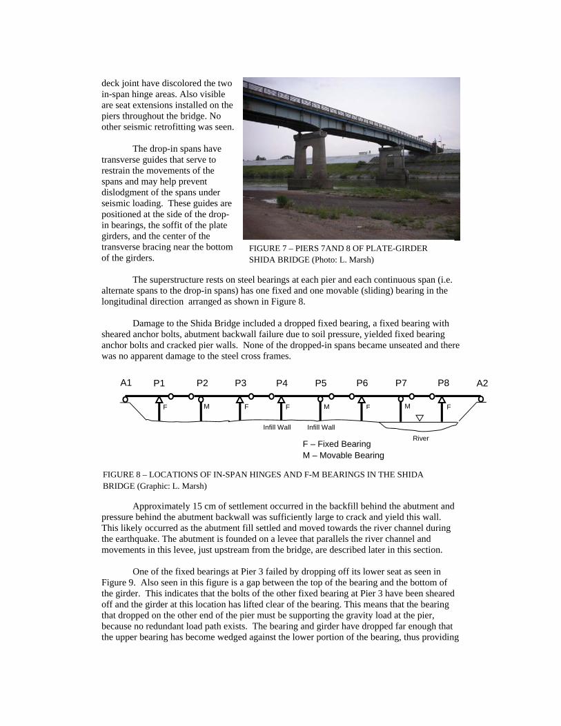
deck joint have discolored the two in-span hinge areas. Also visible are seat extensions installed on the piers throughout the bridge. No other seismic retrofitting was seen.
The drop-in spans have
transverse guides that serve to restrain the movements of the spans and may help prevent dislodgment of the spans under seismic loading. These guides are positioned at the side of the drop-in bearings, the soffit of the plate girders, and the center of the transverse bracing near the bottom of the girders.
The superstructure rests on steel bearings at each pier and each continuous span (i.e. alternate spans to the drop-in spans) has one fixed and one movable (sliding) bearing in the longitudinal direction arranged as shown in Figure 8.
Damage to the Shida Bridge included a dropped fixed bearing, a fixed bearing with sheared anchor bolts, abutment backwall failure due to soil pressure, yielded fixed bearing anchor bolts and cracked pier walls. None of the dropped-in spans became unseated and there was no apparent damage to the steel cross frames.
Approximately 15 cm of settlement occurred in the backfill behind the abutment and
pressure behind the abutment backwall was sufficiently large to crack and yield this wall. This likely occurred as the abutment fill settled and moved towards the river channel during the earthquake. The abutment is founded on a levee that parallels the river channel and movements in this levee, just upstream from the bridge, are described later in this section.
One of the fixed bearings at Pier 3 failed by dropping off its lower seat as seen in Figure 9. Also seen in this figure is a gap between the top of the bearing and the bottom of the girder. This indicates that the bolts of the other fixed bearing at Pier 3 have been sheared off and the girder at this location has lifted clear of the bearing. This means that the bearing that dropped on the other end of the pier must be supporting the gravity load at the pier, because no redundant load path exists. The bearing and girder have dropped far enough that the upper bearing has become wedged against the lower portion of the bearing, thus providing
F M
A1 P1 P2 P3 P4 P5 P6 P7 P8 A2
Infill Wall Infill Wall
River F – Fixed Bearing M – Movable Bearing
F F F F M M
FIGURE 7 – PIERS 7AND 8 OF PLATE-GIRDER SHIDA BRIDGE (Photo: L. Marsh)
FIGURE 8 – LOCATIONS OF IN-SPAN HINGES AND F-M BEARINGS IN THE SHIDA BRIDGE (Graphic: L. Marsh)

vertical support. It is likely that the upper bolts of the left-hand bearing sheared before the right-hand bearing dropped from its pedestal. There is no vertical load path through the bearing pin to sustain tensile forces on the bolts and thus shear is the probable mode of failure. Following loss of shear capacity on the left side, all shear for this frame would have to be resisted by the right-hand bearing. This increase in shear demand likely caused the right-hand bearing to unseat. Failure of this bearing is probably the reason for the noticeable dip in the elevation of the bridge roadway and handrail (estimated at 10 cm) seen in Figure 10. It also possible that some of this deformation is due to foundation settlement due to widespread liquefaction in the area.
Pier 3 is one of the infill-wall piers. The infill probably increased the stiffness at Pier
3 in the longitudinal direction which the forces in the fixed bearing resulting in this dropped bearing. Close inspection of the anchor bolts at the top of the left side of Pier 3 indicates that those bolts were elongated or hammered outward more than any of the bolts on the other fixed piers of the bridge. This leads to the conclusion that the forces were higher at Pier 3 due to the infill wall.
Following the unseating of the right-hand bearing at Pier 3, the superstructure moved towards Abutment 1 as indicated by the final location of the right hand bearing at Pier 3. This is confirmed by the observed movement in the expansion bearing at Abutment 1 as indicated in Figure 11. The cracks in the masonry pedestal beneath the girder indicate that the shear keys were engaged as the superstructure moved in this direction.
Left Right
Roller bearing at Pier 2
Pier 3
Sheared Bolts at Pier 3
Sheared Bolts at Pier 3
Dropped bearing at Pier 3
FIGURE 9 – UNSEATING AND FAILURE OF BEARINGS AT PIER 3, SHIDA BRIDGE (Photos and Graphic: E. Monzon)

At two other fixed piers, Pier 1 and Pier 6, the anchor bolts between the bearing and the top of the pier were either elongated or pulled out of their embedment by the longitudinal inertial action of the superstructure. The longi-tudinal response of the bridge was probably limited by the yielding or slippage of these bolts, and this action provided partial force limitation. However, it was not enough to prevent damage to the piers below the bearings. At both Piers 1 and 6, moderate cracking and potential yielding occurred. Figure 12 shows examples of such damage, and in fact both piers were undergoing repair at the time of the reconnaissance visit. This is evident by the scaffolding and enclosures present at these piers.
It is likely, due to the rust present in the exposed reinforcement of Pier 6, that delamination of the reinforcement had been present for some time before the March 2011 earthquake. Due to the age of the bridge – built in 1957 – it is likely to have experienced other significant earthquakes. Repairs to other piers, in particular the infill wall piers was evident, and it is not known if the infills were repairs to earthquake damage or were added at the time of construction.
While investigating the performance of the Shida bridge, it was observed that the crest of an 8-m high levee along the Naruse River just upstream of the bridge had settled 1.0 to 1.5 m. This settlement was accompanied by a lateral toe movement of up to 4 to 5 m downstream and significant slumping on the downstream face. Due to concern that the levee might completely fail during the upcoming rainy season, a temporary repair was constructed consisting of a 240-m long, 3.8-m high, 4.5-m wide, double sided sheet pile cofferdam on top of a 3.8-m high berm.
FIGURE 10 – SETTLEMENT IN BARRIER AND DECK AT PIER 3, SHIDA BRIDGE (Photo: D. Frost)
FIGURE 11 – DAMAGE TO PEDESTAL AND ABUT-MENT BACKWALL, SHIDA BRIDGE (Photo: E. Monzon)
P1
A1
FIGURE 12 – FLEXURAL DAMAGE IN PIER 1 DUE TO LONGITUDINAL MOVEMENT, SHIDA BRIDGE (Photos and Graphic: E. Monzon)

Bridge Damage due to Tsunami Inundation
Twelve bridges on Route 45 were seriously damaged by the tsunami, which had wave heights from Sendai to Hachinohe ranging from 6.2 to 11.8 m. Damage to two of these bridges and nearby rail bridges are described in this section. Koizumi Highway and Rail Bridges
The Koizumi bridge spans the Tsuya River on Route 45 just south of the city of Kesennuma. The bridge was constructed in 1975, has six 30.1-m spans (total length 182 m), and is 11.3-m wide. The superstructure comprised four steel plate girders supported by concrete piers on deep foundations. The bridge is without skew and only a slight vertical curve. The superstructure segments were continuous over three spans with expansion joints at the abutments and at the center pier (Pier 3). Piers 2 and 4 had fixed bearings, while Piers 1 and 5 had sliding bearings in the longitudinal direction.
The bridge had been seismically retrofitted using hydraulic dampers at the abutments. It is not known if similar restrainers or dampers had been installed at the expansion joint over the center pier. No other retrofitting, such as support length extensions or substructure strengthening was evident.
All six spans were swept away during the tsunami (Figure 13). Wave heights of the order of 11.8 m were registered at Ofunato City just north of this site and the tsunami clearly overtopped this bridge taking all six spans upstream. Based on damage to the levee on the north bank of the river, some of these spans were lifted off their piers and swept along the top of the levee on the north bank, then over the levee altogether on the north side, and later back over the levee into the main channel where they came to rest about 400 m upstream from the bridge (Figure 14). Other spans took a different path and came to rest about 300 m upstream but on the south side of the levee on the south bank of the river. Four of the five piers are still standing, but the center pier (Pier 3) was overturned and believed to be under water in the river channel just upstream of the bridge (Figure 13).
FIGURE 13 – REMAINING PIERS OF KOIZUMI BRIDGE. TEMPORARY BRIDGE IS UNDER CONSTRUCTION ON SEAWARD-SIDE OF ORIGINAL BRIDGE (Photo: E. Monzon)

It is clear that the longitudinal dampers installed at the abutments and the transverse keys (stoppers) over the piers, offered little restraint to the lateral loads imposed by tsunami. Once these devices failed, the relatively light weight of the steel I-girders, together with the buoyancy effects of air trapped between the girders, enabled the superstructure to be easily lifted and carried significant distances upstream. The loss of Pier 3 was probably due to scour but this could not be confirmed. Despite the low tide at the time of the visit, the foundation was still underwater.
About 900 m upstream of the Koizumi Bridge, the JR East rail line to Kesennuma crosses the Tsuya River on a multispan, prestressed concrete girder viaduct. Five of these spans were washed out, but the piers survived (Figure 15). The in-coming tsunami apparently breached the levee behind the piers allowing flow oblique to the channel. The piers are tilted toward the breach, and the simple span, three-girder superstructures came to rest on the opposite side of the levee.
Of interest is the damage to the lower portions of the piers. The exposed reinforcement seen on the left side of the each pier appears to have been pulled outward from the center of the column and rupturing the relatively light transverse steel. This type of behavior is seen in the failure of beams that are unreinforced for shear, where a shear crack precipitates failure and tearing of the tensile reinforcement from the beam. In the case of the JR East piers, potential buoyancy of the superstructure due to trapped air and the hydrodynamic forces produced lateral loads on the piers along with eccentric vertical loading. The piers may have failed in shear above the foundation after plastically deforming under the combined lateral and vertical effects. Following the loss of shear capacity at the base, the tension reinforcement was torn from the piers.
In this postulated mode of failure the tilting of the pier is due to structural failure and not to scour and subsequent rotation of the foundation. Inspection of the columns and footings below the water line is required to confirm this behavior.
FIGURE 14 – GIRDERS FROM KOIZUMI BRIDGE 400m UPSTREAM IN TSUYA RIVER CHANNEL (Photo: E. Monzon)
FIGURE 15 – DAMAGED PIERS OF THE JR RAIL VIADUCT AT THE TSUYA RIVER (Photo: S. Dashti)

Nijyu-ichihama Highway and Rail Bridges The Nijyu-ichihama highway bridge spans a small stream on Route 45 south of
Kesennuma and the Koizumi and Sodeo-gawa bridges. This bridge was built in 1971 and is a single-span prestressed concrete I-girder bridge supported on tall, cantilever abutments, which are in turn supported on steel pipe piles. The bridge has no skew, no curve and essentially no grade. The span is 16.64 m and the total width of the original structure is 8.7 m. End diaphragms engage each of the eleven I-girders comprising the deck and in turn, and were anchored to the abutment seats with tie-down rods in each bay. These same diaphragms acted as transverse shear keys restraining the lower flange of each girder from lateral movement.
The bridge has been widened on both sides at some time in the past using precast double-tee beams spanning between new abutments each founded on steel piles with heads at a much higher elevation than those of the original structure. The tsunami washed out the backfill behind both abutments and temporary approach spans, using steel I-girders, were placed to open the road to traffic. These spans are seen in Figure 16. Temporary steel towers to support these spans may also be seen in this figure.
Apart from the loss of the seaward extension, this bridge has performed remarkably well from a structural point of view. It is essentially intact and the principal reason for closure was the loss of back fill due to erosion. Despite the buoyancy of trapped air, the superstructure was well anchored both vertically and laterally to the abutment seats and was not dislodged by the tsunami despite being overtopped. It is of course possible that the erosion of the abutment backfills and the opening up of two alternative hydraulic channels took load off the bridge, but nevertheless the performance of this bridge under these circumstances is noteworthy.
About 100 meters upstream from the Nijyu-ichihama bridge is the JR East line to Kennesuma, which runs a distance of several hundred meters across the valley between tunnels at either end. This section of rail line was supported on a long fill embankment, two box culvert roadway underpasses, and a prestressed concrete, single span
FIGURE 16 – LOSS OF BACKFILL ON BOTH APPROACHES TO SINGLE-SPAN NIJYU-ICHIHAMA BRIDGE (Photo: L. Marsh)
FIGURE 17 – EXPOSED WINGWALLS OF JR RAIL BRIDGE 100m UPSTREAM OF NIJYU-ICHIHAMA BRIDGE DUE TO LOSS OF APPROACH EMBANKMENT (Photo: D. Frost)

bridge over the river (Figure 17). The unprotected embankment fill appeared to be a granular material. As the wave overtopped the embankment, it displaced the tracks and significantly scoured and removed the upper 4 to 5 m of the fill. Apart from the loss of the approach fills, all the bridges in the valley appeared to be intact. Preliminary Conclusions
The following conclusions are based on observations made, and data recovered, during this reconnaissance exercise. They are, however, of a speculative nature due to the small number of bridges investigated and the absence of detailed field data such as foundation and soil details, bearing and tie-down details, superstructure weights, wave heights, and velocity profiles at each site. These conclusions are therefore likely to change as additional data becomes available and further studies are completed.
1. Despite the magnitude of this earthquake, bridge damage outside of the coastal zone was not heavy. This is believed to be partly due to the distance from the epicentral region, and partly to the fact that a conservative form of capacity design was implemented in Japan for new bridges in the 1990s. Furthermore an active retrofit program was undertaken for older bridges following the Kobe earthquake in 1995, especially on the national highway system.
2. Aftershocks that follow large magnitude main events can, themselves, be large and damaging. The damage sustained by some bridges was aggravated in subsequent aftershocks.
3. Retrofitting is an effective means for minimizing earthquake damage in older bridges. Most of the observed structural damage occurred in older bridges that had not yet been retrofitted, or only partly so. It is recommended that strong encouragement be given to owner agencies to accelerate their retrofit programs.
4. With the exception of several spans in the Sendai area, elastomeric bearings performed well and considerably better than older-style, steel bearings. The reason for the poor performance of the Sendai-Tobu bearings needs to be determined quickly for it has widespread implications on their growing worldwide use as movement and isolation bearings.
5. Damage to several older, un-retrofitted, bridge piers was concentrated in the reinforcement termination zone, and this vulnerability should be considered when prioritizing bridges for retrofitting. Bridges damaged in this manner are susceptible to additional damage during aftershocks that will lead to longer repair times and more restrictive load limits or even closure during repair.
6. Design methods to mitigate tsunami damage from inundation should be developed. Strategies to keep superstructures in place (such as using integral connections and venting trapped air to reduce buoyancy and equalize hydrostatic pressures on deck slabs) should be explored, along with armoring techniques to prevent undue scour of foundations and approach fills. In addition, the cost of deeper foundations should be weighed against the potential loss of a pier and the need for replacement of one or more spans.

7. Until analytical studies are complete it is not known to what extent the duration of this earthquake affected the observed damage, but it is expected to have been significant. The effect of duration on structural response should be investigated.
Acknowledgements The team was hosted in Japan by Task Committee G of the UJNR Panel on Wind and Seismic Effects. Membership was as follows: U.S. Members: Ian Buckle, Professor, University of Nevada Reno, Reno Shideh Dashti, Professor, University of Colorado at Boulder, Boulder David Frost, Professor, Georgia Institute of Technology, Atlanta Lee Marsh, Senior Project Manager, Berger/ABAM Engineers, Seattle Eric Monzon, Graduate Research Assistant, University of Nevada Reno, Reno W. Phillip Yen, Federal Highway Administration, Washington DC (Co-chair) Japan Members: Taku Hanai, Public Works Research Institute, Tsukuba Jun-ichi Hoshikuma, Public Works Research Institute, Tsukuba Kazuhiko Kawashima, Tokyo Institute of Technology, Tokyo Teturou Kuwabara, Public Works Research Institute, Tsukuba (Co-chair) Hideaki Nishida, Public Works Research Institute, Tsukuba Keiichi Tamura, Public Works Research Institute, Tsukuba Shigeki Unjoh, National Institute for Land and Infrastructure Management The collegiality of members of the Japan team, the free exchange of technical data, the excellent field logistics, and many useful discussions about bridge performance are gratefully acknowledged. Acknowledgement is also made of generous funding provided by EERI, by FHWA under Contract DTFH61-07-C-00031 to the University of Nevada Reno, and by GEER under NSF Award #CMMI-1138203 to University of California, Davis. References EERI, 2011. RAPID Proposal- Performance and Resilience Data Recovery from the Great East (Tohoku-Oki) Japan Earthquake Considering Bridges Buildings and Government and Community Response, Proposal to National Science Foundation, Earthquake Engineering Research Institute, Oakland CA. EERI, 2011. Bridge Performance During the Great East Japan Earthquake of March 11, 2011, Reconnaissance Report, to be published, Earthquake Engineering Research Institute, Oakland CA. FHWA, 2011. Bridge Performance During the Great East Japan Earthquake of March 11, 2011, Reconnaissance Report, to be published, Federal Highway Administration, Washington DC.