bpn-sas3-826el1-n4 backplane...bpn-sas3-826el1-n4 backplane user’s guide preface iv v returning...
TRANSCRIPT

BPN-SAS3-826EL1-N4 BACKPLANE
USER'S GUIDE
Rev. 1.0
A 1E
5
H
5
1AEH
AC
A
C
17
25
26 50
51
75
76100
1
3
1
3
BPN-SAS3-826EL1-N4 REV:1.00
SAS CODE
A CA
C
ACA C
+
+ +
+
3 2 14
3 2 14
1 4
1 4
1 4 1 4
1
4
67
8913
12 22
A1 A2
A7 A
8
CG1
CG2
B1 B2B7 B8
C1 C2C7 C8
D1
D2
D7 D8
CG3
E1E2G
2
F2F1
H2H
1
G1
F7 F8G8
E7G7
H7
H8
E8
PRES
S FI
T
A1
A2
A7 A
8CG
1
CG2
B1 B2B7 B8
C1 C2C7 C8
D1
D2
D7 D8
CG3
E1E2G
2
F2F1
H2H
1
G1
F7 F8G8
E7G7
H7
H8
E8
PRES
S FI
T
A1
A2
A7 A
8CG
1
CG2
B1 B2B7 B8
C1 C2C7 C8
D1
D2
D7 D8
CG3
E1E2G
2
F2F1
H2H
1
G1
F7 F8G8
E7G7
H7
H8
E8
PRES
S FI
T
A1 A2
A7 A
8
CG1
CG2
B1 B2B7 B8
C1 C2C7 C8
D1
D2
D7 D8
CG3
E1E2G
2
F2F1
H2H
1
G1
F7 F8G8 E7
G7
H7
H8 E8
PRES
S FI
T
1
510
1520
2526
AF
AEYRKEA
123
123
1
DESIGNED IN USA
BAR CODE
67
1213
24 7
12
24
U136
R399Q43
L2
D32
D31
JP2
J24
J23
L3
Q17
L1
LED29LED27
LED26LED25
L29
C188
C194
C192
C193
J21 J20U22
J22
J18
JPW2JPW1
JPW3
U11
OSC1
U143
U19
U14
U13
U16
U3
C7C6
C206C205 C186C187
J15
J14
J16
J17
MH7MH6MH9MH8
MH5
MH1
MH2
MH3
U9
U30
U7
JP1
U26
R44
R400
R108
R97
R110
R183 R182
C30
C17
C486C485
C14
CPU2 0 3 2 1
: 2: 3
: 1: 4
CPU1J242-3
2-31-2
1-21-21-2
2-32-3
J23
NVM
e4N
VMe3
NVMe2
NVM
e1
CPLD
SAS P1
SAS P3
SAS P2
SAS P4
I2C#4 UART 12V 5V
HB-LED
SDBI2C#0
TESTACT-LED
Preface
iiiii
Contents
Contacting Supermicro .......................................................................................iv Returning Merchandise for Service.....................................................................v
Chapter 1 Guidelines1-1 ESD Safety Guidelines ................................................................................... 1-11-2 General Safety Guidelines .............................................................................. 1-11-3 Version Information ......................................................................................... 1-2
Chapter 2 Connectors, Jumpers and LEDs2-1 Rear Connector Locations .............................................................................. 2-12-2 RearConnectorandPinDefinitions ............................................................... 2-22-3 RearJumperLocationsandPinDefinitions ................................................... 2-3
Explanation of Jumpers .................................................................................. 2-32-4 Front Connectors and LED Indicators ............................................................ 2-4
Chapter 3 Cascading Configurations3-1 Single Port Expanders .................................................................................... 3-1
Single Ports ..................................................................................................... 3-1Connecting an External HBA to the Backplane ............................................. 3-2Single External Host Bus Adapter ................................................................. 3-2Connecting Multiple Backplanes in a Single Channel Environment ............... 3-3SingleHBAConfigurationCables ................................................................... 3-4
Manual Revision 1.0 Release Date: January 25, 2017
TheinformationinthisUser’sManualhasbeencarefullyreviewedandisbelievedtobeaccurate.Thevendorassumesnoresponsibilityforanyinaccuraciesthatmaybecontainedinthisdocument,makes no commitment to update or to keep current the information in this manual, or to notify any person or organization of the updates. Please Note: For the most up-to-date version of this manual, please see our web site at www.supermicro.com.
Super Micro Computer, Inc. ("Supermicro") reserves the right to make changes to the product described in this manual at any time and without notice. This product, including software anddocumentation, is the property of Supermicro and/or its licensors, and is supplied only under a license.Anyuseor reproductionof thisproduct isnotallowed,exceptasexpresslypermittedbythe terms of said license.
IN NO EVENT WILL SUPERMICRO BE LIABLE FOR DIRECT, INDIRECT, SPECIAL, INCIDENTAL, SPECULATIVE OR CONSEQUENTIAL DAMAGES ARISING FROM THE USE OR INABILITY TO USE THIS PRODUCT OR DOCUMENTATION, EVEN IF ADVISED OF THE POSSIBILITY OF SUCH DAMAGES. IN PARTICULAR, SUPERMICRO SHALL NOT HAVE LIABILITY FOR ANY HARDWARE, SOFTWARE, OR DATA STORED OR USED WITH THE PRODUCT, INCLUDING THE COSTS OF REPAIRING, REPLACING, INTEGRATING, INSTALLING OR RECOVERING SUCH HARDWARE, SOFTWARE, OR DATA. Any disputes arising between manufacturer and customer shall be governed by the lawsof Santa Clara County in the State of California, USA. The State of California, County of Santa Clara shall be the exclusive venue for the resolution of any such disputes. SuperMicro's total liability for all claims will not exceed the price paid for the hardware product. California Best Management Practices Regulations for Perchlorate Materials: This Perchlorate warningappliesonlytoproductscontainingCR(ManganeseDioxide)Lithiumcoincells.“PerchlorateMaterial-specialhandlingmayapply.Seewww.dtsc.ca.gov/hazardouswaste/perchlorate”
WARNING: Handling of lead solder materials used in this product may expose you to lead, a chemical known tothe State of California to cause birth defects and otherreproductive harm.
UnlessyourequestandreceivewrittenpermissionfromSuperMicroComputer,Inc.,youmaynotcopy any part of this document.
Informationinthisdocumentissubjecttochangewithoutnotice.Otherproductsandcompaniesreferred to herein are trademarks or registered trademarks of their respective companies or mark holders.
Copyright©2017bySuperMicroComputer,Inc. All rights reserved. Printed in the United States of America
PrefaceBPN-SAS3-826EL1-N4 Backplane User’s Guide
iv v
Returning Merchandise for Service
Areceiptorcopyofyourinvoicemarkedwiththedateofpurchaseisrequiredbeforeanywarrantyservicewillberendered.YoucanobtainservicebycallingyourvendorforaReturnedMerchandiseAuthorization (RMA)number.When returning to themanufacturer,theRMAnumbershouldbeprominentlydisplayedontheoutsideofthe shipping carton, and mailed prepaid or hand-carried. Shipping and handling chargeswillbeappliedforallordersthatmustbemailedwhenserviceiscomplete.
For faster service, RMA authorizations may be requested online (http://www.supermicro.com/support/rma/).
Wheneverpossible,repackthebackplaneintheoriginalSupermicrobox,usingtheoriginalpackagingmaterials.Ifthesearenolongeravailable,besuretopackthebackplaneinananti-staticbagandinsidethebox.Makesurethatthereisenoughpackagingmaterialsurroundingthebackplanesothatitdoesnotbecomedamagedduring shipping.
This warranty only covers normal consumer use and does not cover damagesincurredinshippingorfromfailureduetothealteration,misuse,abuseorimpropermaintenance of products.
Duringthewarrantyperiod,contactyourdistributorfirstforanyproductproblems.
Contacting Supermicro
HeadquartersAddress: Super Micro Computer, Inc.
980 Rock Ave.
San Jose, CA 95131 U.S.A.
Tel: +1 (408) 503-8000
Fax: +1 (408) 503-8008
Email: [email protected] (General Information)
[email protected] (Technical Support)
Website: www.supermicro.com
EuropeAddress: Super Micro Computer B.V.
HetSterrenbeeld28,5215ML
's-Hertogenbosch,TheNetherlands
Tel: +31 (0) 73-6400390
Fax: +31 (0) 73-6416525
Email: [email protected] (General Information)
[email protected] (Technical Support)
[email protected] (Customer Support)
Website: www.supermicro.nl
Asia-PacificAddress: Super Micro Computer, Inc.
3F, No. 150, Jian 1st Rd.
ZhongheDist.,NewTaipeiCity235
Taiwan(R.O.C)
Tel: +886-(2) 8226-3990
Fax: +886-(2) 8226-3992
Email: [email protected]
Website: www.supermicro.com.tw

BPN-SAS3-826EL1-N4 Backplane User’s Guide
vi
Notes
1-1
Chapter 1 Guidelines
Chapter 1
Guidelines
Thischapteroffersguidelinesforpersonalandequipmentsafety,andnotesaboutthe BPN-SAS3-826EL1-N4 version documented in this manual.
1-1 ESD Safety Guidelines
Electrostatic Discharge (ESD) can damage electronic com ponents. To prevent dam-age to your system, it is important to handle it very carefully. The following measures are generally sufficient to protect your equipment from ESD.
• Useagroundedwriststrapdesignedtopreventstaticdischarge.
• Touchagroundedmetalobjectbeforeremovingacomponentfromtheantistaticbag.
• Handlethebackplanebyitsedgesonly;donottouchitscomponents,peripheralchips, memory modules or gold contacts.
• When handling chips or modules, avoid touching their pins.
• Putthecardandperipheralsbackintotheirantistaticbagswhennotinuse.
1-2 General Safety Guidelines
• Alwaysdisconnectpowercablesbeforeinstallingorremovinganycomponentsfromthecomputer,includingthebackplane.
• Disconnect thepower cordbefore installingor removinganycables from thebackplane.
• Makesurethatthebackplaneissecurelyandproperlyinstalledonthemountingframeinthechassistopreventdamagetothesystemduetopowershortage.

1-2
BPN-SAS3-826EL1-N4 Backplane User's Guide
1-3 Version Information
The BPN-SAS3-826EL1-N4 backplane has been designed to utilize the mostup-to-date technology available, providing your systemwith reliable, high-qualityperformance.
ThismanualreflectsBPN-SAS3-826EL1-N4,themostcurrentreleaseavailableatthetimeofpublication.AlwaysrefertotheSupermicrowebsiteatwww.supermicro.comforthelatestupdates,compatiblepartsandsupportedconfigurations.
2-1
Chapter 2: Connectors Jumpers and LEDs
Chapter 2
Connectors, Jumpers and LEDs
ThismanualcoversBPN-SAS3-826EL1-N4withNVMecapabilities.
2-1 Rear Connector Locations
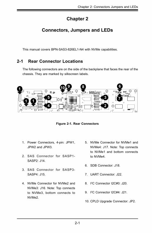
Thefollowingconnectorsareonthesideofthebackplanethatfacestherearofthechassis.Theyaremarkedbysilkscreenlabels.
A 1E
5
H
5
1AEH
AC
A
C
17
25
26 50
51
75
76100
1
3
1
3
BPN-SAS3-826EL1-N4 REV:1.00
SAS CODE
A CA
C
ACA C
+
+ +
+
3 2 14
3 2 14
1 4
1 4
1 4 1 4
1
4
67
8913
12 22
A1 A2
A7 A
8
CG1
CG2
B1 B2B7 B8
C1 C2C7 C8
D1
D2
D7 D8
CG3
E1E2G
2
F2F1
H2H
1
G1
F7 F8G8
E7G7
H7
H8
E8
PRES
S FI
T
A1
A2
A7 A
8CG
1
CG2
B1 B2B7 B8
C1 C2C7 C8
D1
D2
D7 D8
CG3
E1E2G
2
F2F1
H2H
1
G1
F7 F8G8
E7G7
H7
H8
E8
PRES
S FI
T
A1
A2
A7 A
8CG
1
CG2
B1 B2B7 B8
C1 C2C7 C8
D1
D2
D7 D8
CG3
E1E2G
2
F2F1
H2H
1
G1
F7 F8G8
E7G7
H7
H8
E8
PRES
S FI
T
A1 A2
A7 A
8
CG1
CG2
B1 B2B7 B8
C1 C2C7 C8
D1
D2
D7 D8
CG3
E1E2G
2
F2F1
H2H
1
G1
F7 F8G8 E7
G7
H7
H8 E8
PRES
S FI
T
1
510
1520
2526
AF
AEYRKEA
123
123
1
DESIGNED IN USA
BAR CODE
67
1213
24 7
12
24
U136
R399Q43
L2
D32
D31
JP2
J24
J23
L3
Q17
L1
LED29LED27
LED26LED25
L29
C188
C194
C192
C193
J21 J20U22
J22
J18
JPW2JPW1
JPW3
U11
OSC1
U143
U19
U14
U13
U16
U3
C7C6
C206C205 C186C187
J15
J14
J16
J17
MH7MH6MH9MH8
MH5
MH1
MH2
MH3
U9
U30
U7
JP1
U26
R44
R400
R108
R97
R110
R183 R182
C30
C17
C486C485
C14
CPU2 0 3 2 1
: 2: 3
: 1: 4
CPU1J242-3
2-31-2
1-21-21-2
2-32-3
J23
NVM
e4N
VMe3
NVMe2
NVM
e1
CPLD
SAS P1
SAS P3
SAS P2
SAS P4
I2C#4 UART 12V 5V
HB-LED
SDBI2C#0
TESTACT-LED
1. Power Connectors, 4-pin: JPW1,JPW2 and JPW3.
2. SAS Connector for SASP1-SASP2: J14.
3. SAS Connector for SASP3-SASP4: J15.
4. NVMe Connector for NVMe2 and NVMe3: J16. Note: Top connects to NVMe3, bottom connects toNVMe2.
5. NVMe Connector for NVMe1 and NVMe4: J17. Note: Top connects to NVMe1 and bottom connectsto NVMe4.
6. SDB Connector: J18.
7. UART Connector: J22.
8. I2C Connector I2C#0: J20.
9. I2C Connector I2C#4: J21.
10. CPLD Upgrade Connector: JP2.
11
11 111214
1315
1819110 66
17
Figure 2-1. Rear Connectors
2-3
Chapter 2: Connectors Jumpers and LEDs
2-2
BPN-SAS3-826EL1-N4 Backplane User's Guide
A 1E
5
H
5
1AEH
AC
A
C
17
25
26 50
51
75
76100
1
3
1
3
BPN-SAS3-826EL1-N4 REV:1.00
SAS CODE
A CA
C
ACA C
+
+ +
+
3 2 14
3 2 14
1 4
1 4
1 4 1 4
1
4
67
8913
12 22
A1 A2
A7 A
8
CG1
CG2
B1 B2B7 B8
C1 C2C7 C8
D1
D2
D7 D8
CG3
E1E2G
2
F2F1
H2H
1
G1
F7 F8G8
E7G7
H7
H8
E8
PRES
S FI
T
A1
A2
A7 A
8CG
1
CG2
B1 B2B7 B8
C1 C2C7 C8
D1
D2
D7 D8
CG3
E1E2G
2
F2F1
H2H
1
G1
F7 F8G8
E7G7
H7
H8
E8
PRES
S FI
T
A1
A2
A7 A
8CG
1
CG2
B1 B2B7 B8
C1 C2C7 C8
D1
D2
D7 D8
CG3
E1E2G
2
F2F1
H2H
1
G1
F7 F8G8
E7G7
H7
H8
E8
PRES
S FI
T
A1 A2
A7 A
8
CG1
CG2
B1 B2B7 B8
C1 C2C7 C8
D1
D2
D7 D8
CG3
E1E2G
2
F2F1
H2H
1
G1
F7 F8G8 E7
G7
H7
H8 E8
PRES
S FI
T
1
510
1520
2526
AF
AEYRKEA
123
123
1
DESIGNED IN USA
BAR CODE
67
1213
24 7
12
24
U136
R399Q43
L2
D32
D31
JP2
J24
J23
L3
Q17
L1
LED29LED27
LED26LED25
L29
C188
C194
C192
C193
J21 J20U22
J22
J18
JPW2JPW1
JPW3
U11
OSC1
U143
U19
U14
U13
U16
U3
C7C6
C206C205 C186C187
J15
J14
J16
J17
MH7MH6MH9MH8
MH5
MH1
MH2
MH3
U9
U30
U7
JP1
U26
R44
R400
R108
R97
R110
R183 R182
C30
C17
C486C485
C14
CPU2 0 3 2 1
: 2: 3
: 1: 4
CPU1J242-3
2-31-2
1-21-21-2
2-32-3
J23
NVM
e4N
VMe3
NVMe2
NVM
e1
CPLD
SAS P1
SAS P3
SAS P2
SAS P4
I2C#4 UART 12V 5V
HB-LED
SDBI2C#0
TESTACT-LED
BackplaneMain Power
4-Pin Connector
Pin#Definition
1 +12V
2 and 3 Ground
4 +5V
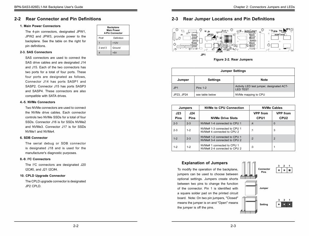
1. Main Power Connectors
The 4-pin connectors, designated JPW1, JPW2 and JPW3, provide power to thebackplane. See the table on the right forpindefinitions.
2-3. SAS Connectors
SAS connectors are used to connect the SASdrivecablesandaredesignatedJ14andJ15.Eachof the twoconnectorshastwo ports for a total of four ports. Thesefour ports are designated as follows,Connector J14 has ports SASP1 and SASP2. Connector J15 has ports SASP3 and SASP4. These connectors are also compatiblewithSATAdrives.
4.-5. NVMe Connectors
TwoNVMeconnectorsareusedtoconnectthe NVMe drive cables. Each connectorcontrolstwoNVMeSSDsforatotaloffourSSDs. Connector J16 is for SSDs NVMe2 and NVMe3. Connector J17 is for SSDs NVMe1 and NVMe4.
6. SDB Connector
The serial debug or SDB connectoris designated J18 and is used for the manufacturer's diagnostic purposes.
8.-9. I2C Connectors
The I2C connectors are designated J20 I2C#0, and J21 I2C#4.
10. CPLD Upgrade Connector
The CPLD upgrade connector is designated JP2 CPLD.
2-2 RearConnectorandPinDefinitions
JP1JP24
JP1
JP23
2-3 RearJumperLocationsandPinDefinitions
Explanation of JumpersTomodify theoperationof thebackplane,jumpers can be used to choose betweenoptional settings. Jumpers create shorts between two pins to change the functionof the connector. Pin 1 is identified witha square solder pad on the printed circuit board.Note:Ontwopinjumpers,"Closed"meansthejumperisonand"Open"meansthejumperisoffthepins.
ConnectorPins
Jumper
Setting
3 2 1
3 2 1
Jumper Settings
Jumper Settings Note
JP1 Pins 1-2 ActivityLEDtestjumper,designatedACT-LED TEST
JP23, JP24 seetablebelow NVMe mapping to CPU
Jumpers NVMe to CPU Connection NVMe CablesJ23 Pins
J24 Pins NVMe Drive Slots
VPP from CPU1
VPP from CPU2
2-3 2-3 NVMe# 1-4 connected to CPU 1 :4 0
2-3 1-2 NVMe# 1-3 connected to CPU 1 NVMe# 4 connected to CPU 2 :1 3
1-2 2-3 NVMe# 1-2 connected to CPU 1 NVMe# 3-4 connected to CPU 2 :2 2
1-2 1-2 NVMe# 1 connected to CPU 1 NVMe# 2-4 connected to CPU 2 :3 1
Figure 2-2. Rear Jumpers
2-4
BPN-SAS3-826EL1-N4 Backplane User's Guide
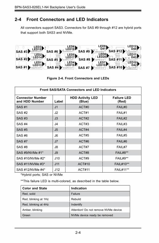
2-4 Front Connectors and LED Indicators
AllconnectorssupportSAS3.ConnectorsforSAS#9through#12arehybridportsthatsupportbothSAS3andNVMe.
Front SAS/SATA Connectors and LED Indicators
Connector Number and HDD Number Label
HDD Activity LED (Blue)
Failure LED (Red)
SAS #1 J1 ACT#0 FAIL#0
SAS #2 J2 ACT#1 FAIL#1
SAS #3 J3 ACT#2 FAIL#2
SAS #4 J4 ACT#3 FAIL#3
SAS #5 J5 ACT#4 FAIL#4
SAS #6 J6 ACT#5 FAIL#5
SAS #7 J7 ACT#6 FAIL#6
SAS #8 J8 ACT#7 FAIL#7
SAS #9/NVMe #1* J9 ACT#8 FAIL#8**
SAS #10/NVMe #2* J10 ACT#9 FAIL#9**
SAS #11/NVMe #3* J11 ACT#10 FAIL#10**
SAS #12/NVMe #4* J12 ACT#11 FAIL#11***Hybridports;SASorNVMe
**ThisfailureLEDismulti-colored,asdescribedinthetablebelow.
Color and State IndicationRed, solid Failure
Red,blinkingat1Hz Rebuild
Red,blinkingat4Hz Indentify
Amber,blinking Attention! Do not remove NVMe device
Green NVMedevicereadyberemoved
S1 S7 P1 P15E1 E6
E7 S8 S28 E17 E25E16
S1 S7 P1 P15E1 E6
E7 S8 S28 E17E25
E16
S1 S7 P1 P15E1 E6
E7 S8 S28 E17 E25E16
S1
S7P1
P15
E1E6
E7S8 S28 E17 E25E16
A
C
A
C
A
C
A
C
A
C
71
3
1
31
A
C
A
C
A
C
A
C
A
C
A
C
A
C
A
C
A
C
A
C
A
C
A
C
A
C
A
C
A
C
A
C
A
C
A
C
A
C
A
C
321 4321 44 1
4 1
4 14
1
4
1
A7A
8
A1
A2
CG1
B1B2
B7B8
C1C2
C7C8
D1
D2
D7
D8
E8
E7E1
E2 G2
F2 F1
H2 H
1
G1
G8
F8 F7 H8
H7
G7
A7A
8
A1
A2 B1
B2B7B8
C1C2
C7C8
D1
D2
D7
D8
CG3
E8
E7E1
E2 G2
F2 F1
H2 H
1
G1
G8
F8 F7 H8
H7
G7
A7A
8
A1
A2
CG1
CG2
B1B2
B7B8
C1C2
C7C8
D1
D2
D7
D8
CG3
E8
E7E1
E2 G2
F2 F1
H2 H
1
G1
G8
F8 F7 H8
H7
G7
A7A
8
A1
A2
CG1
CG2
B1B2
B7B8
C1C2
C7C8
D1
D2
D7
D8
CG3
E8
E7E1
E2 G2
F2 F1
H2 H
1
G1
G8
F8 F7 H8
H7
G7
1
P1
P15
S14
S1 P1
P15S8 S14
S1
S1 P1
P15
S14
S1 P1P15
S14
S1 S7 P1P15S8 S14
S1 S7 P1S8 S14
S1 P1 P15S14
U134
Q41U1
J9 J12
J11
J10
D27
D41D44
D42D43
LED20LED19
LED18LED17
LED16
LED15
LED14
LED13
LED9LED8
LED7
LED6LED5
LED4
LED3LED2
LED12LED11
LED10
LED1 L12
U29
U23
C703
C705
C704 C701
C375
J4
J6
J7
J8
J1
J2
J3
J5
R262R71
R265
C118C119
C120
C249C248C121
NVMe4
NVMe3
NVMe2
NVMe1SAS#12
SAS#11
SAS#10
SAS#9
SAS#8
SAS#7
SAS#6
SAS#5
SAS#4
SAS#3
SAS#2
SAS#1
Figure 2-4. Front Connectors and LEDs
LED4LED16
SAS #4
LED12D44
SAS #12LED11
D43SAS #11
LED10D42
SAS #10
LED9D41
SAS #9LED8
LED20SAS #8
LED7LED19
SAS #7
LED6LED18
SAS #6LED5
LED17SAS #5
LED3LED15
SAS #3LED2
LED14SAS #2LED1
LED13SAS #1
3-1
Chapter 3 Cascading Configurations
A 1E
5
H
5
1AEH
AC
A
C
17
25
26 50
51
75
76100
1
3
1
3
BPN-SAS3-826EL1-N4 REV:1.00
SAS CODE
A CA
C
ACA C
+
+ +
+
3 2 14
3 2 14
1 4
1 4
1 4 1 4
1
4
67
8913
12 22
A1 A2
A7 A
8
CG1
CG2
B1 B2B7 B8
C1 C2C7 C8
D1
D2
D7 D8
CG3
E1E2G
2
F2F1
H2H
1
G1
F7 F8G8
E7G7
H7
H8
E8
PRES
S FI
T
A1
A2
A7 A
8CG
1
CG2
B1 B2B7 B8
C1 C2C7 C8
D1
D2
D7 D8
CG3
E1E2G
2
F2F1
H2H
1
G1
F7 F8G8
E7G7
H7
H8
E8
PRES
S FI
T
A1
A2
A7 A
8CG
1
CG2
B1 B2B7 B8
C1 C2C7 C8
D1
D2
D7 D8
CG3
E1E2G
2
F2F1
H2H
1
G1
F7 F8G8
E7G7
H7
H8
E8
PRES
S FI
T
A1 A2
A7 A
8
CG1
CG2
B1 B2B7 B8
C1 C2C7 C8
D1
D2
D7 D8
CG3
E1E2G
2
F2F1
H2H
1
G1
F7 F8G8 E7
G7
H7
H8 E8
PRES
S FI
T
1
510
1520
2526
AF
AEYRKEA
123
123
1
DESIGNED IN USA
BAR CODE
67
1213
24 7
12
24
U136
R399Q43
L2
D32
D31
JP2
J24
J23
L3
Q17
L1
LED29LED27
LED26LED25
L29
C188
C194
C192
C193
J21 J20U22
J22
J18
JPW2JPW1
JPW3
U11
OSC1
U143
U19
U14
U13
U16
U3
C7C6
C206C205 C186C187
J15
J14
J16
J17
MH7MH6MH9MH8
MH5
MH1
MH2
MH3
U9
U30
U7
JP1
U26
R44
R400
R108
R97
R110
R183 R182
C30
C17
C486C485
C14
CPU2 0 3 2 1
: 2: 3
: 1: 4
CPU1J242-3
2-31-2
1-21-21-2
2-32-3
J23
NVM
e4N
VMe3
NVMe2
NVM
e1
CPLD
SAS P1
SAS P3
SAS P2
SAS P4
I2C#4 UART 12V 5V
HB-LED
SDBI2C#0
TESTACT-LED
From HBA or Higher Backplane
Chapter 3
CascadingConfigurations
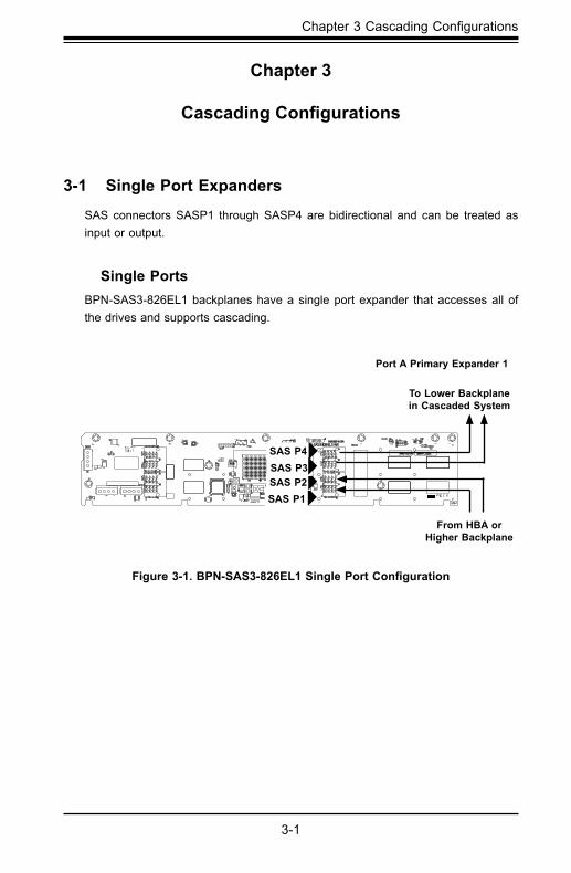
3-1 Single Port Expanders
SASconnectorsSASP1 throughSASP4are bidirectional and can be treated asinput or output.
Single PortsBPN-SAS3-826EL1backplaneshaveasingleportexpander thataccessesallofthe drives and supports cascading.
To Lower Backplane in Cascaded System
Port A Primary Expander 1
Figure3-1.BPN-SAS3-826EL1SinglePortConfiguration
SAS P4
SAS P1SAS P2SAS P3
3-3
Chapter 3 Cascading Configurations
3-2
BPN-SAS3-826EL1-N4 Backplane User's Guide
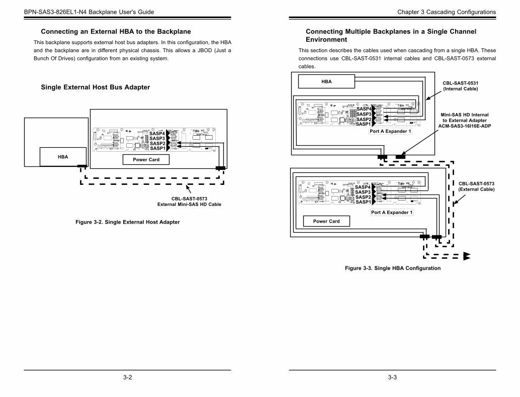
Connecting an External HBA to the Backplane Thisbackplanesupportsexternalhostbusadapters.Inthisconfiguration,theHBAand the backplaneare in different physical chassis.This allowsa JBOD (Just aBunchOfDrives)configurationfromanexistingsystem.
HBA Power Card
CBL-SAST-0573 External Mini-SAS HD Cable
Figure 3-2. Single External Host Adapter
Single External Host Bus Adapter
A 1E
5
H
5
1AEH
AC
A
C
17
25
26 50
51
75
76100
1
3
1
3
BPN-SAS3-826EL1-N4 REV:1.00
SAS CODE
A CA
C
ACA C
+
+ +
+
3 2 14
3 2 14
1 4
1 4
1 4 1 4
1
4
67
8913
12 22
A1 A2
A7 A
8
CG1
CG2
B1 B2B7 B8
C1 C2C7 C8
D1
D2
D7 D8
CG3
E1E2G
2
F2F1
H2H
1
G1
F7 F8G8
E7G7
H7
H8
E8
PRES
S FI
T
A1
A2
A7 A
8CG
1
CG2
B1 B2B7 B8
C1 C2C7 C8
D1
D2
D7 D8
CG3
E1E2G
2
F2F1
H2H
1
G1
F7 F8G8
E7G7
H7
H8
E8
PRES
S FI
T
A1
A2
A7 A
8CG
1
CG2
B1 B2B7 B8
C1 C2C7 C8
D1
D2
D7 D8
CG3
E1E2G
2
F2F1
H2H
1
G1
F7 F8G8
E7G7
H7
H8
E8
PRES
S FI
T
A1 A2
A7 A
8
CG1
CG2
B1 B2B7 B8
C1 C2C7 C8
D1
D2
D7 D8
CG3
E1E2G
2
F2F1
H2H
1
G1
F7 F8G8 E7
G7
H7
H8 E8
PRES
S FI
T
1
510
1520
2526
AF
AEYRKEA
123
123
1
DESIGNED IN USA
BAR CODE
67
1213
24 7
12
24
U136
R399Q43
L2
D32
D31
JP2
J24
J23
L3
Q17
L1
LED29LED27
LED26LED25
L29
C188
C194
C192
C193
J21 J20U22
J22
J18
JPW2JPW1
JPW3
U11
OSC1
U143
U19
U14
U13
U16
U3
C7C6
C206C205 C186C187
J15
J14
J16
J17
MH7MH6MH9MH8
MH5
MH1
MH2
MH3
U9
U30
U7
JP1
U26
R44
R400
R108
R97
R110
R183 R182
C30
C17
C486C485
C14
CPU2 0 3 2 1
: 2: 3
: 1: 4
CPU1J242-3
2-31-2
1-21-21-2
2-32-3
J23
NVM
e4N
VMe3
NVMe2
NVM
e1
CPLD
SAS P1
SAS P3
SAS P2
SAS P4
I2C#4 UART 12V 5V
HB-LED
SDBI2C#0
TESTACT-LED
CBL-SAST-0531 (Internal Cable)
CBL-SAST-0573 (External Cable)
Mini-SAS HD Internal to External Adapter
ACM-SAS3-16I16E-ADP
HBA
Power Card
Port A Expander 1
Connecting Multiple Backplanes in a Single Channel Environment
ThissectiondescribesthecablesusedwhencascadingfromasingleHBA.Theseconnections use CBL-SAST-0531 internal cables and CBL-SAST-0573 externalcables.
Figure3-3.SingleHBAConfiguration
Port A Expander 1
A 1E
5
H
5
1AEH
AC
A
C
17
25
26 50
51
75
76100
1
3
1
3
BPN-SAS3-826EL1-N4 REV:1.00
SAS CODE
A CA
C
ACA C
+
+ +
+
3 2 14
3 2 14
1 4
1 4
1 4 1 4
1
4
67
8913
12 22
A1 A2
A7 A
8
CG1
CG2
B1 B2B7 B8
C1 C2C7 C8
D1
D2
D7 D8
CG3
E1E2G
2
F2F1
H2H
1
G1
F7 F8G8
E7G7
H7
H8
E8
PRES
S FI
T
A1
A2
A7 A
8CG
1
CG2
B1 B2B7 B8
C1 C2C7 C8
D1
D2
D7 D8
CG3
E1E2G
2
F2F1
H2H
1
G1
F7 F8G8
E7G7
H7
H8
E8
PRES
S FI
T
A1
A2
A7 A
8CG
1
CG2
B1 B2B7 B8
C1 C2C7 C8
D1
D2
D7 D8
CG3
E1E2G
2
F2F1
H2H
1
G1
F7 F8G8
E7G7
H7
H8
E8
PRES
S FI
T
A1 A2
A7 A
8
CG1
CG2
B1 B2B7 B8
C1 C2C7 C8
D1
D2
D7 D8
CG3
E1E2G
2
F2F1
H2H
1
G1
F7 F8G8 E7
G7
H7
H8 E8
PRES
S FI
T
1
510
1520
2526
AF
AEYRKEA
123
123
1
DESIGNED IN USA
BAR CODE
67
1213
24 7
12
24
U136
R399Q43
L2
D32
D31
JP2
J24
J23
L3
Q17
L1
LED29LED27
LED26LED25
L29
C188
C194
C192
C193
J21 J20U22
J22
J18
JPW2JPW1
JPW3
U11
OSC1
U143
U19
U14
U13
U16
U3
C7C6
C206C205 C186C187
J15
J14
J16
J17
MH7MH6MH9MH8
MH5
MH1
MH2
MH3
U9
U30
U7
JP1
U26
R44
R400
R108
R97
R110
R183 R182
C30
C17
C486C485
C14
CPU2 0 3 2 1
: 2: 3
: 1: 4
CPU1J242-3
2-31-2
1-21-21-2
2-32-3
J23
NVM
e4N
VMe3
NVMe2
NVM
e1
CPLD
SAS P1
SAS P3
SAS P2
SAS P4
I2C#4 UART 12V 5V
HB-LED
SDBI2C#0
TESTACT-LED
SASP1SASP2SASP3SASP4
SASP4 SASP3 SASP2 SASP1
SASP4 SASP3 SASP2 SASP1
3-5
Chapter 3 Cascading Configurations
3-4
BPN-SAS3-826EL1-N4 Backplane User's Guide
Cable Name:16-portMini-SASHDInternaltoExternalCableAdapterwithLPBracket
Part #: AOM-SAS3-16I16E-LPPorts:Fourwide-ports(sixteenportstotal)Placement: InternalcablewithadapterDescription: Internalcable,connectstheSAS3backplanetoexternalports.
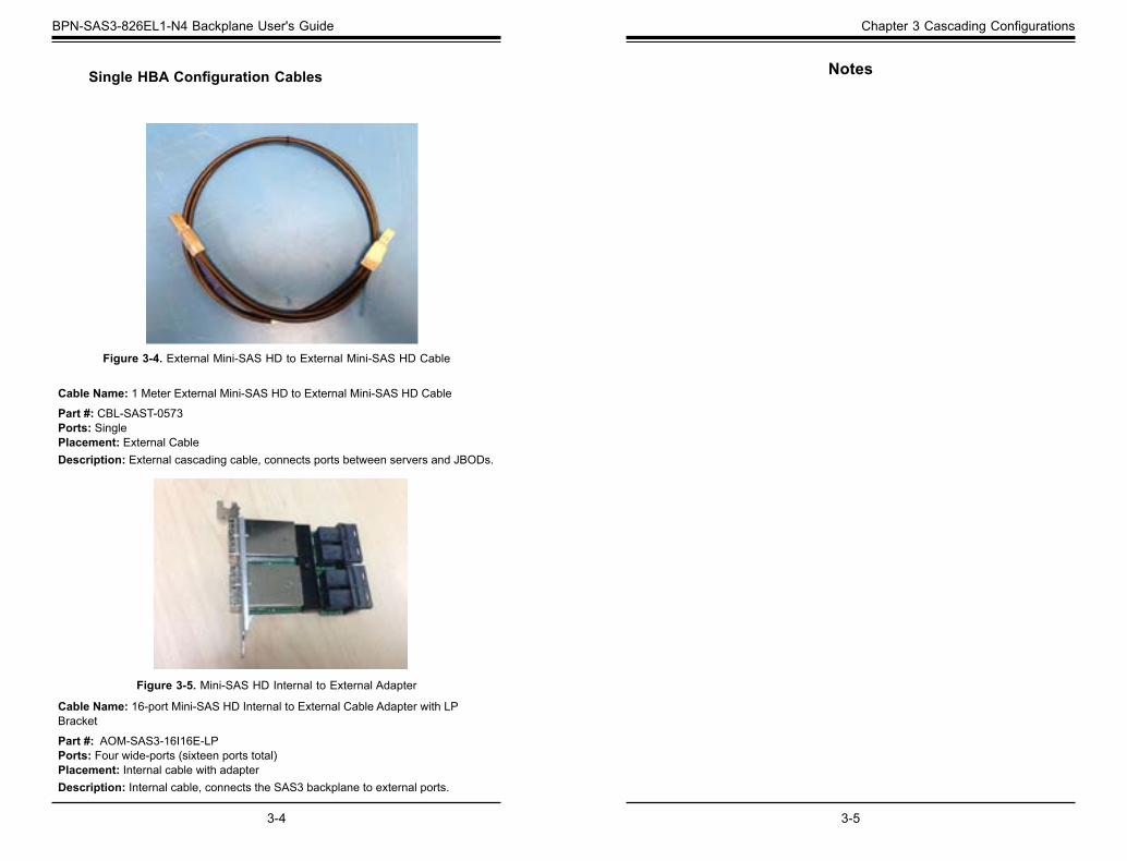
Cable Name: 1MeterExternalMini-SASHDtoExternalMini-SASHDCablePart #: CBL-SAST-0573Ports: SinglePlacement: ExternalCableDescription:Externalcascadingcable,connectsportsbetweenserversandJBODs.
SingleHBAConfigurationCables
Figure 3-4. ExternalMini-SASHDtoExternalMini-SASHDCable
Figure 3-5. Mini-SAS HD Internal to External Adapter
Notes

3-6
BPN-SAS3-826EL1-N4 Backplane User's Guide
Disclaimer (cont.)TheproductssoldbySupermicroarenotintendedforandwillnotbeusedinlifesup-port systems, medical equipment, nuclear facilities or systems, aircraft, aircraft devices, aircraft/emergencycommunicationdevicesorothercriticalsystemswhosefailuretoper-formbereasonablyexpectedtoresultinsignificantinjuryorlossoflifeorcatastrophicproperty damage.Accordingly, Supermicro disclaims any and all liability, and shouldbuyeruseorsellsuchproductsforuseinsuchultra-hazardousapplications,itdoessoentirelyat itsownrisk.Furthermore,buyeragreestofully indemnify,defendandholdSupermicro harmless for and against any and all claims, demands, actions, litigation, and proceedings of any kind arising out of or related to such ultra-hazardous use or sale.