body builder™s drawings and supporting … · body builder™s drawings and ... 3.1.2 fe85ddz...
TRANSCRIPT
BODY BUILDER�S DRAWINGS AND
SUPPORTING DATA
LIT. No. LTE07001-A
SEP. 2007

INTRODUCTION
This book has been designed to provide information for body and equipment manufacturers who mount their products on MITSUBISHI-FUSO FE chassis. We believe that all the detailed information which is essential for that purpose is contained in this book, but if you require any additional data or information, please contact:
MITSUBISHI FUSO TRUCK OF AMERICA, INC. 2015 Center Square Road, Logan Township, NJ 08085 (Phone : (856) 467-4500)
The specifications and descriptions contined in this book are based on the latest product information at the time of publication, but since the design of MITSUBISHI-FUSO truck is continuously being improved, we must reserve the right to discontinue or change at any time without prior notice.
COMPLIANCE WITH FEDERAL MOTOR VEHICLE SAFETY STANDARDS
The federal government has established Federal Motor Vehicle Safety Standards (FMVSS) for various categories of motor vehicles and motor vehicle equipment under the provisions of the National Traffic and Motor Vehicle Safety Act of 1966. The Act imposes important legal responsibilities on manufacturers, dealers, body builders and others engaged in the marketing of motor vehicles and motor vehicle equipment. Vehicles manufactured by Mitsubishi FUSO Truck & Bus Corporation (MFTBC) for the subsequent installation of commercial bodies are classified as incomplete vehicles. These vehicles fully comply with certain applicable Motor Vehicle Safety Standards, and partially (or do not) comply with others. They cannot be certified fully because certain components which are required for certification are not furnished. Under present federal regulations, vehicles completed from these units are required to meet all applicable standards in effect on the date of manufacture of the incomplete vehicle, the date of final completion, or date between those two dates, as determined by their final configuration. MFTBC incomplete vehicles carry in the glove box a document, as shown on the next page, that provides the vehicle types (truck) into which they may appropriately be completed, and the degree to which the incomplete vehicles comply with each of the standards in effect on the date of its manufacture. The completing manufacturer must certify compliance with all applicable standards, but may rely on MFTBC certification for those standards so indicated in the instructions for completing the vehicle document, provided that the instructions for completing the vehicle are followed. Questions may be directed to the Engineering or Service Department of MFTBC. Alterations, modifications, or additions to the vehicle which affect compliance with FMVSS are not covered by MFTBC certification and are the responsibility of the completing manufacturer. Likewise the completing manufacturer must assume responsibility for compliance with changes in federal requirements that occur after the manufacture of the incomplete vehicle by MFTBC, if he elects to certify compliance as of a later date.
INCOMPLETE VEHICLE DOCUMENT
DO NOT REMOVE
THIS DOCUMENT MUST REMAIN WITH THIS VEHICLE
UNTIL IT IS CERTIFIED AS A COMPLETE VEHICLE
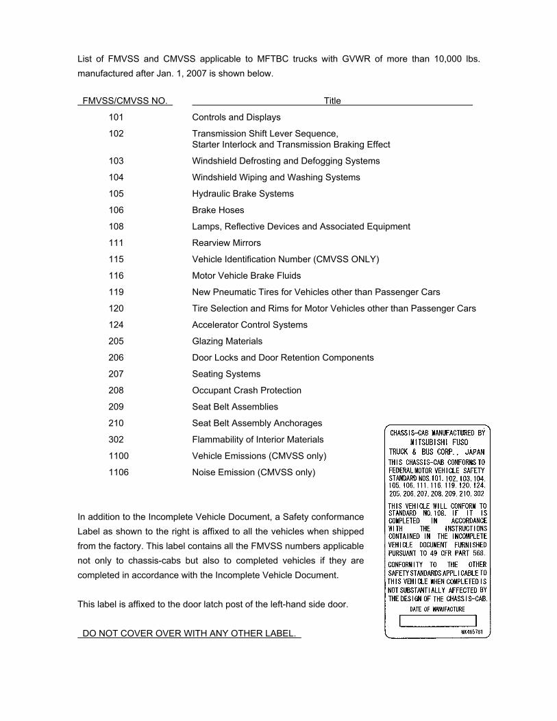
List of FMVSS and CMVSS applicable to MFTBC trucks with GVWR of more than 10,000 lbs. manufactured after Jan. 1, 2007 is shown below. FMVSS/CMVSS NO. Title
101 Controls and Displays
102 Transmission Shift Lever Sequence, Starter Interlock and Transmission Braking Effect
103 Windshield Defrosting and Defogging Systems
104 Windshield Wiping and Washing Systems
105 Hydraulic Brake Systems
106 Brake Hoses
108 Lamps, Reflective Devices and Associated Equipment
111 Rearview Mirrors
115 Vehicle Identification Number (CMVSS ONLY)
116 Motor Vehicle Brake Fluids
119 New Pneumatic Tires for Vehicles other than Passenger Cars
120 Tire Selection and Rims for Motor Vehicles other than Passenger Cars
124 Accelerator Control Systems
205 Glazing Materials
206 Door Locks and Door Retention Components
207 Seating Systems
208 Occupant Crash Protection
209 Seat Belt Assemblies
210 Seat Belt Assembly Anchorages
302 Flammability of Interior Materials
1100 Vehicle Emissions (CMVSS only)
1106 Noise Emission (CMVSS only)
In addition to the Incomplete Vehicle Document, a Safety conformance Label as shown to the right is affixed to all the vehicles when shipped from the factory. This label contains all the FMVSS numbers applicable not only to chassis-cabs but also to completed vehicles if they are completed in accordance with the Incomplete Vehicle Document. This label is affixed to the door latch post of the left-hand side door. DO NOT COVER OVER WITH ANY OTHER LABEL.
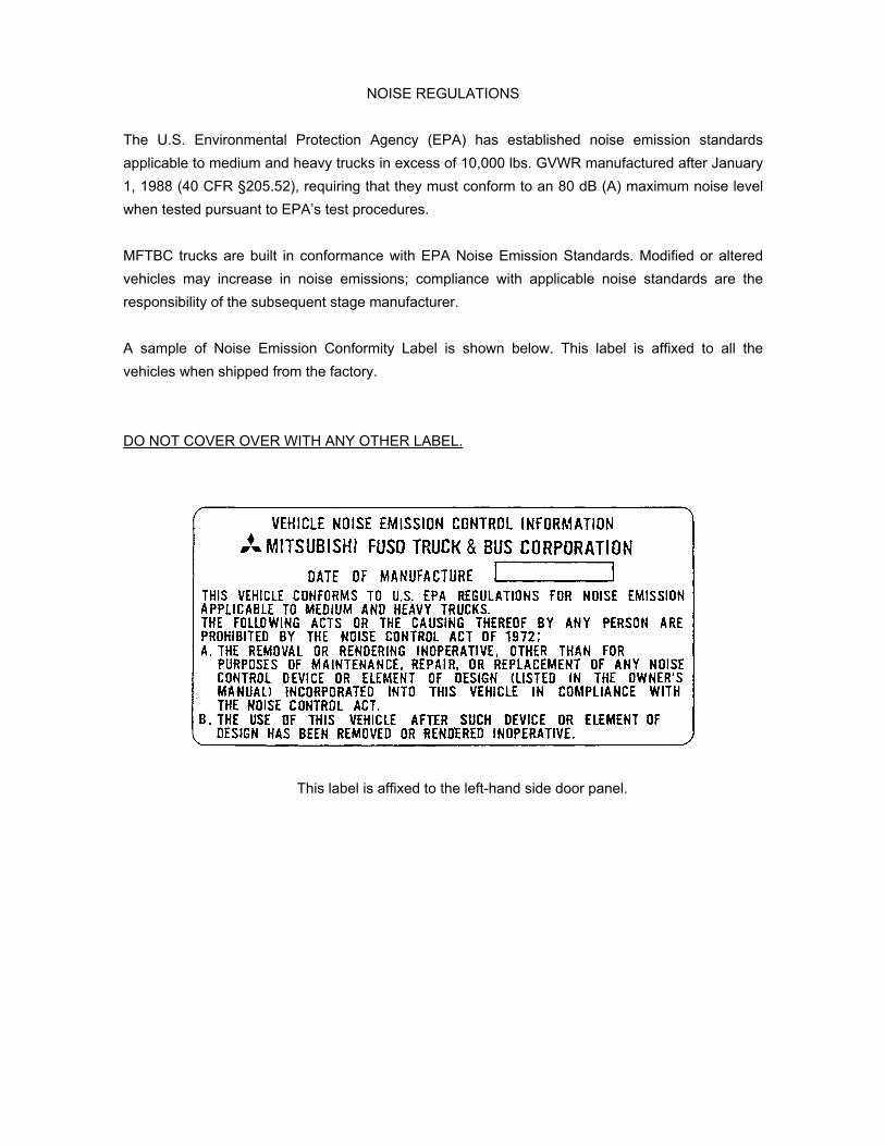
NOISE REGULATIONS
The U.S. Environmental Protection Agency (EPA) has established noise emission standards applicable to medium and heavy trucks in excess of 10,000 lbs. GVWR manufactured after January 1, 1988 (40 CFR §205.52), requiring that they must conform to an 80 dB (A) maximum noise level when tested pursuant to EPA�s test procedures. MFTBC trucks are built in conformance with EPA Noise Emission Standards. Modified or altered vehicles may increase in noise emissions; compliance with applicable noise standards are the responsibility of the subsequent stage manufacturer. A sample of Noise Emission Conformity Label is shown below. This label is affixed to all the vehicles when shipped from the factory. DO NOT COVER OVER WITH ANY OTHER LABEL.
This label is affixed to the left-hand side door panel.

PART II
DRAWINGS AND TECHNICAL DATA
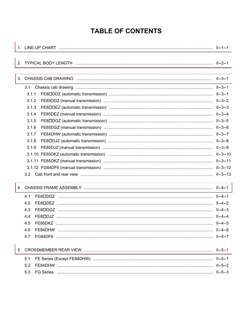
TABLE OF CONTENTS 1. LINE-UP CHART ....................................................................................................................................... II-1-1
2. TYPICAL BODY LENGTH ......................................................................................................................... II-2-1
3. CHASSIS CAB DRAWING ........................................................................................................................ II-3-1
3.1 Chassis cab drawing ........................................................................................................................ II-3-1 3.1.1 FE8!DDZ (automatic transmission) ........................................................................................... II-3-1 3.1.2 FE85DDZ (manual transmission) ................................................................................................ II-3-2 3.1.3 FE8!DEZ (automatic transmission) ........................................................................................... II-3-3 3.1.4 FE85DEZ (manual transmission) ................................................................................................ II-3-4 3.1.5 FE8!DGZ (automatic transmission) ........................................................................................... II-3-5 3.1.6 FE85DGZ (manual transmission) ................................................................................................ II-3-6 3.1.7 FE84DHW (automatic transmission) ........................................................................................... II-3-7 3.1.8 FE8!DJZ (automatic transmission) ............................................................................................ II-3-8 3.1.9 FE85DJZ (manual transmission) ................................................................................................. II-3-9 3.1.10 FE85DKZ (automatic transmission) ............................................................................................ II-3-10 3.1.11 FE85DKZ (manual transmission) ................................................................................................ II-3-11 3.1.12 FG84DF6 (manual transmission) ................................................................................................ II-3-12
3.2 Cab front and rear view .................................................................................................................... II-3-13 4. CHASSIS FRAME ASSEMBLY ................................................................................................................. II-4-1
4.1 FE8!DDZ ........................................................................................................................................ II-4-1 4.2 FE8!DEZ ......................................................................................................................................... II-4-2 4.3 FE8!DGZ ........................................................................................................................................ II-4-3 4.4 FE8!DJZ ......................................................................................................................................... II-4-4 4.5 FE85DKZ .......................................................................................................................................... II-4-5 4.6 FE84DHW ........................................................................................................................................ II-4-6 4.7 FG84DF6 .......................................................................................................................................... II-4-7
5. CROSSMEMBER REAR VIEW ................................................................................................................. II-5-1
5.1 FE Series (Except FE84DHW) ......................................................................................................... II-5-1 5.2 FE84DHW ........................................................................................................................................ II-5-2 5.3 FG Series ......................................................................................................................................... II-5-3
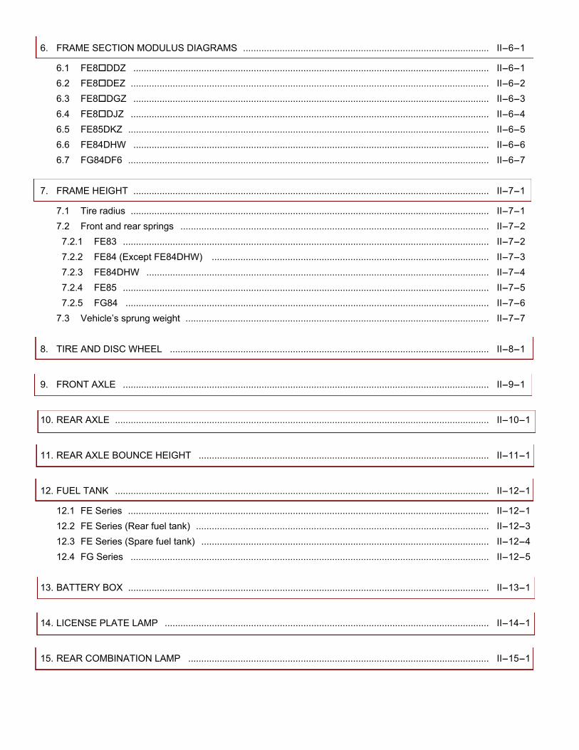
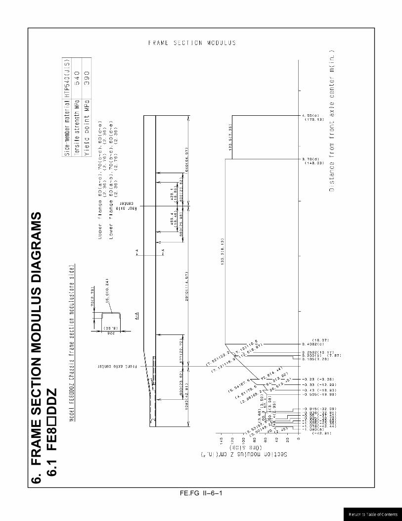
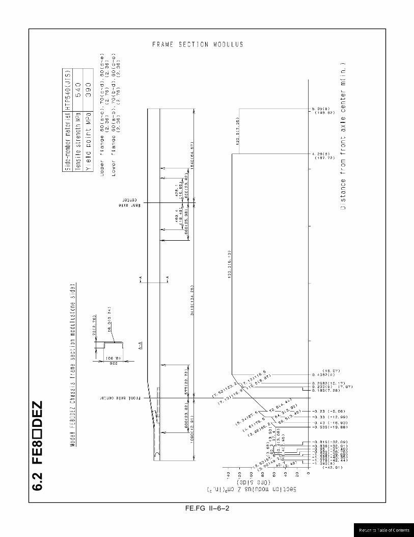
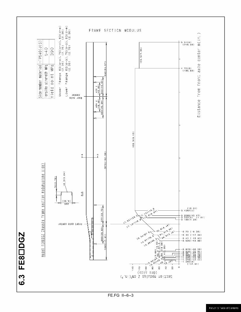
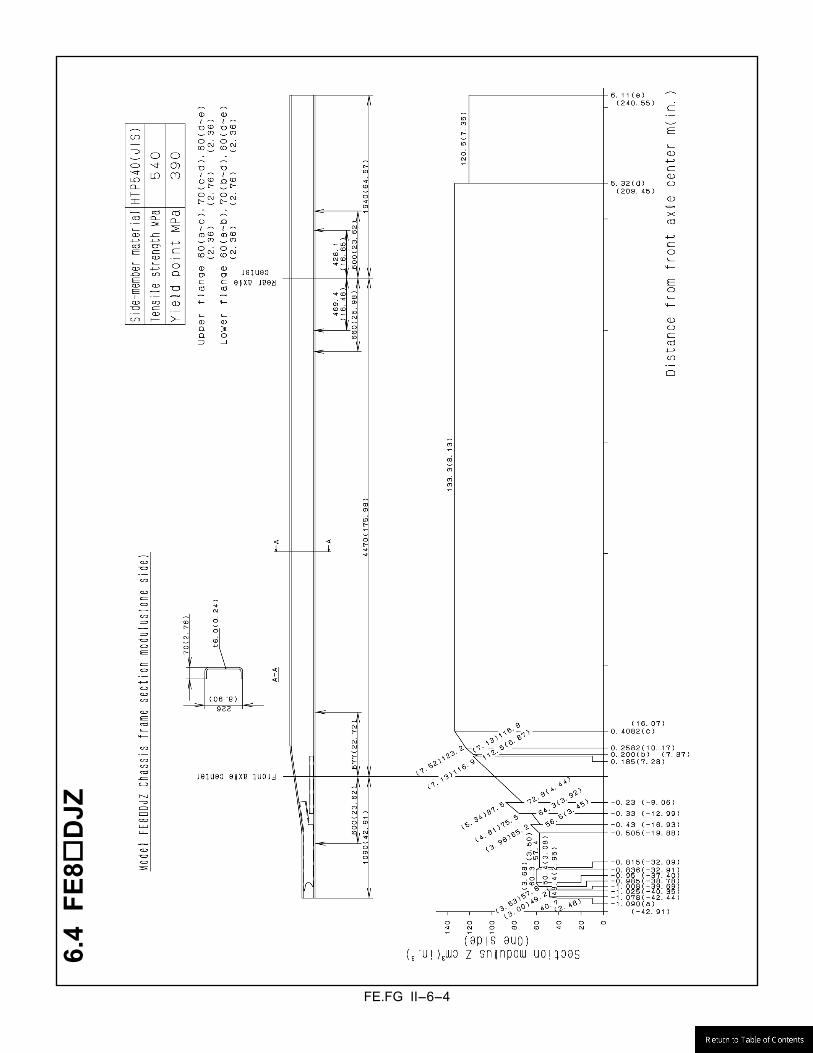
6. FRAME SECTION MODULUS DIAGRAMS .............................................................................................. II-6-1
6.1 FE8!DDZ ........................................................................................................................................ II-6-1 6.2 FE8!DEZ ......................................................................................................................................... II-6-2 6.3 FE8!DGZ ........................................................................................................................................ II-6-3 6.4 FE8!DJZ ......................................................................................................................................... II-6-4 6.5 FE85DKZ .......................................................................................................................................... II-6-5 6.6 FE84DHW ........................................................................................................................................ II-6-6 6.7 FG84DF6 .......................................................................................................................................... II-6-7
7. FRAME HEIGHT ........................................................................................................................................ II-7-1
7.1 Tire radius ......................................................................................................................................... II-7-1 7.2 Front and rear springs ...................................................................................................................... II-7-2
7.2.1 FE83 ............................................................................................................................................ II-7-2 7.2.2 FE84 (Except FE84DHW) .......................................................................................................... II-7-3 7.2.3 FE84DHW ................................................................................................................................... II-7-4 7.2.4 FE85 ............................................................................................................................................ II-7-5 7.2.5 FG84 ........................................................................................................................................... II-7-6
7.3 Vehicle�s sprung weight .................................................................................................................... II-7-7 8. TIRE AND DISC WHEEL .......................................................................................................................... II-8-1
9. FRONT AXLE ............................................................................................................................................ II-9-1
10. REAR AXLE ............................................................................................................................................... II-10-1
11. REAR AXLE BOUNCE HEIGHT ............................................................................................................... II-11-1
12. FUEL TANK ............................................................................................................................................... II-12-1
12.1 FE Series .......................................................................................................................................... II-12-1 12.2 FE Series (Rear fuel tank) ................................................................................................................ II-12-3 12.3 FE Series (Spare fuel tank) .............................................................................................................. II-12-4 12.4 FG Series ......................................................................................................................................... II-12-5
13. BATTERY BOX .......................................................................................................................................... II-13-1
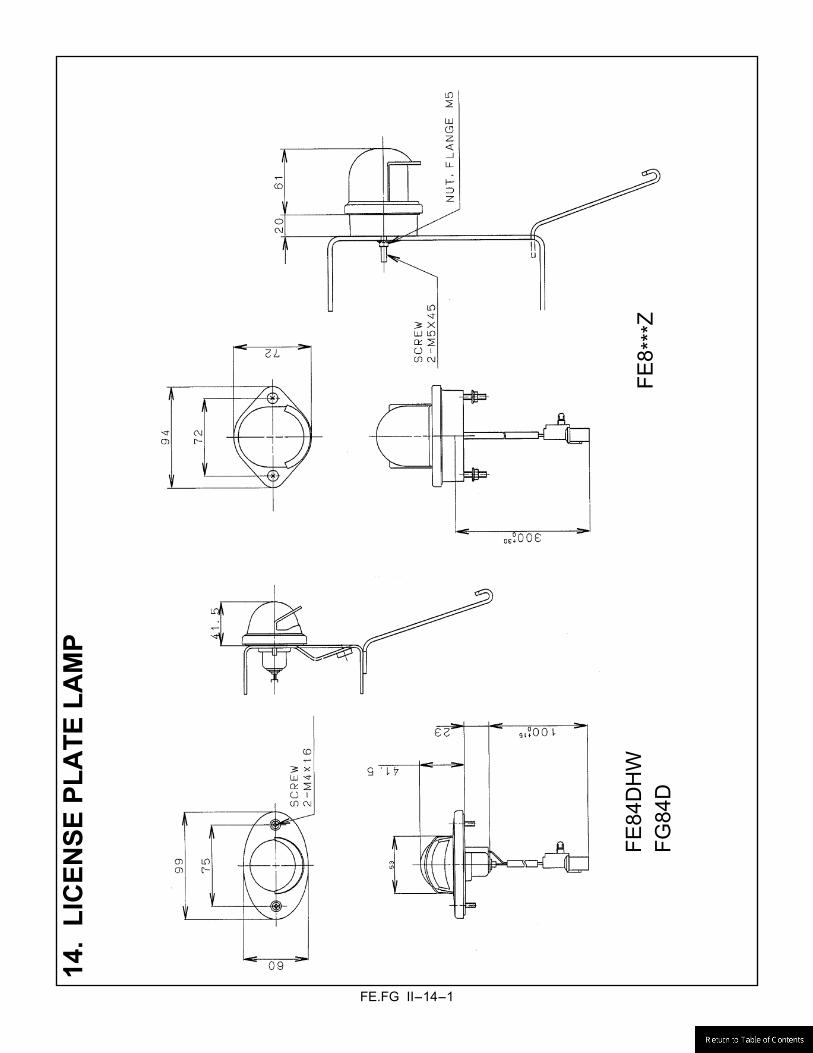
14. LICENSE PLATE LAMP ............................................................................................................................ II-14-1
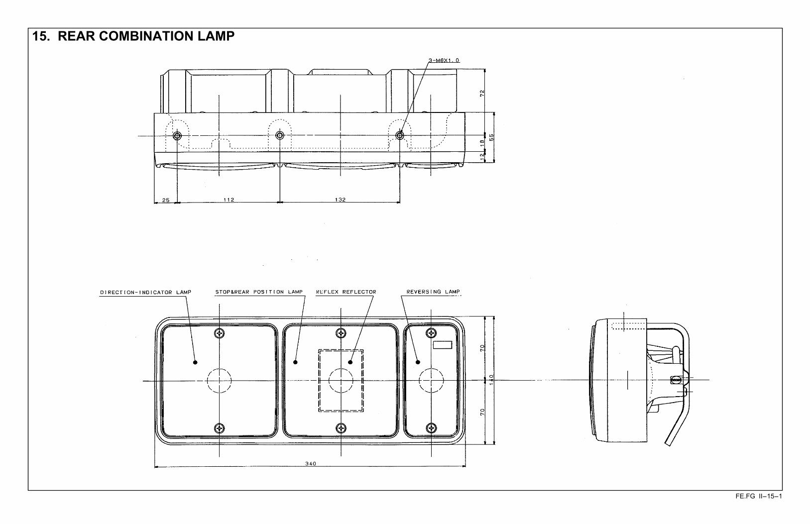
15. REAR COMBINATION LAMP ................................................................................................................... II-15-1
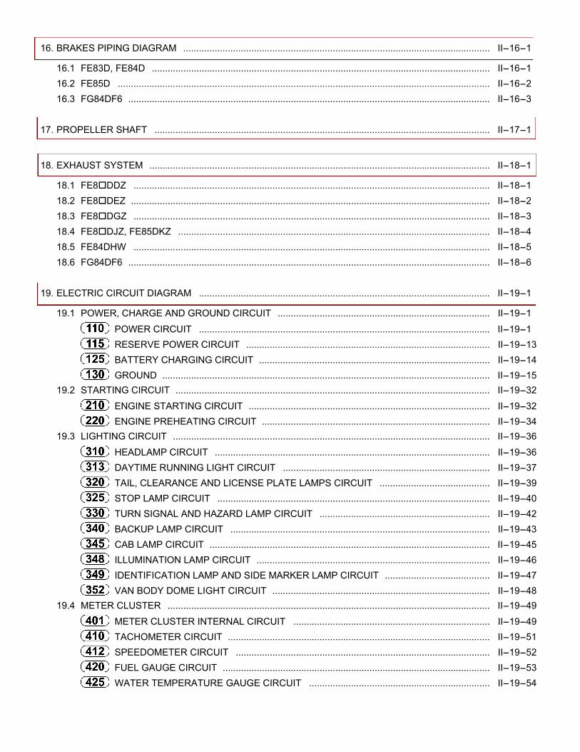
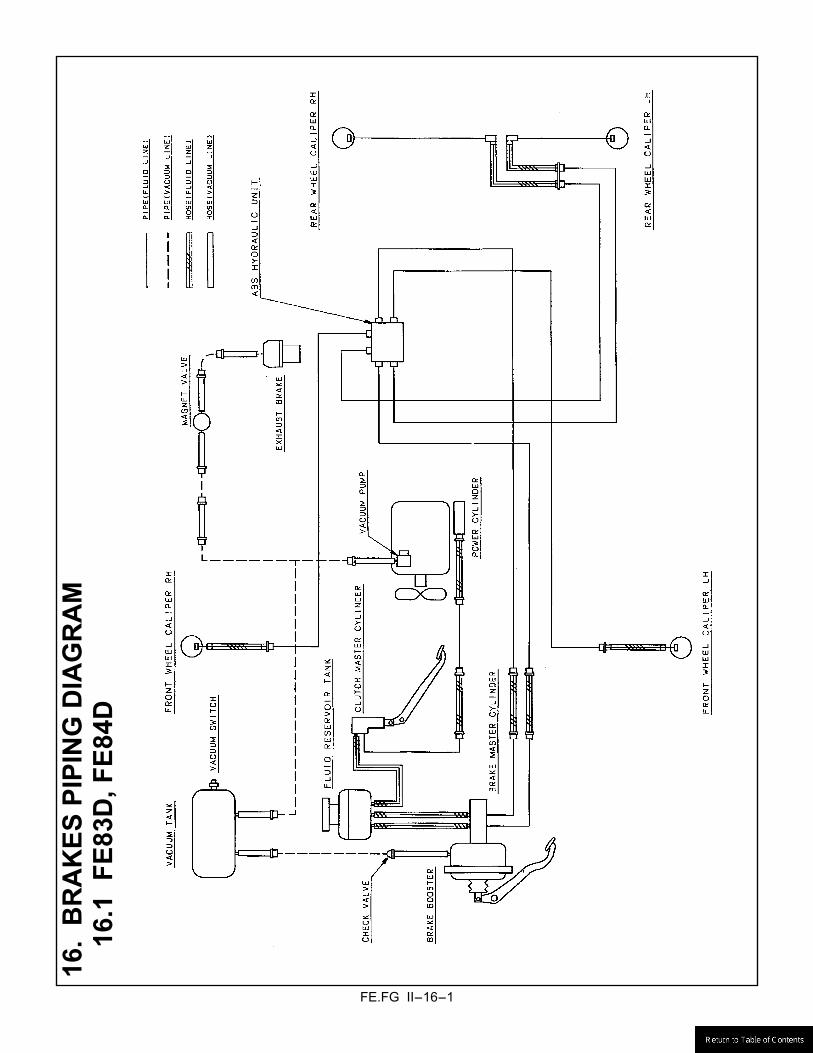
16. BRAKES PIPING DIAGRAM ..................................................................................................................... II-16-1
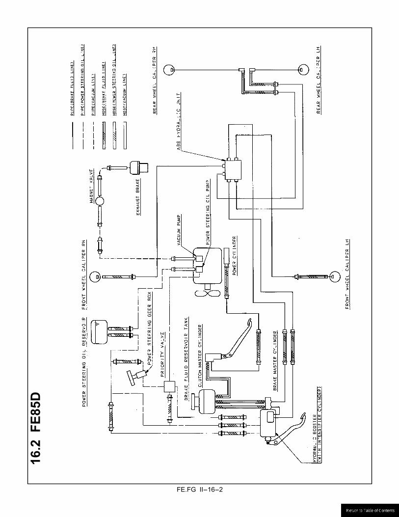
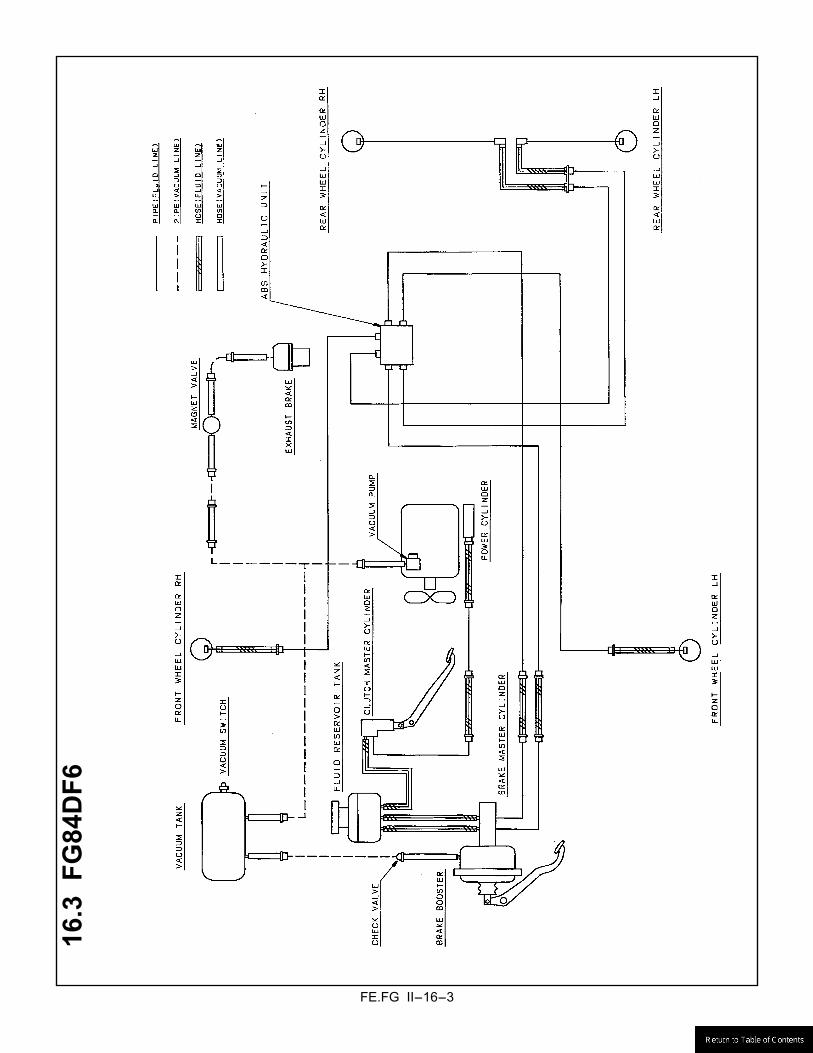
16.1 FE83D, FE84D ................................................................................................................................. II-16-1 16.2 FE85D .............................................................................................................................................. II-16-2 16.3 FG84DF6 .......................................................................................................................................... II-16-3
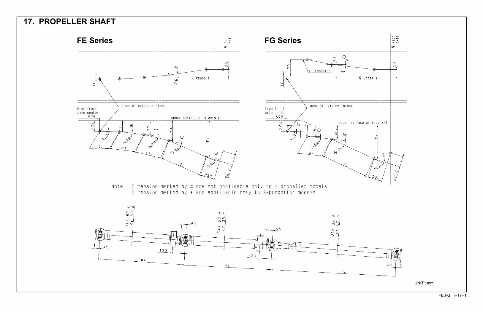
17. PROPELLER SHAFT ................................................................................................................................ II-17-1
18. EXHAUST SYSTEM .................................................................................................................................. II-18-1
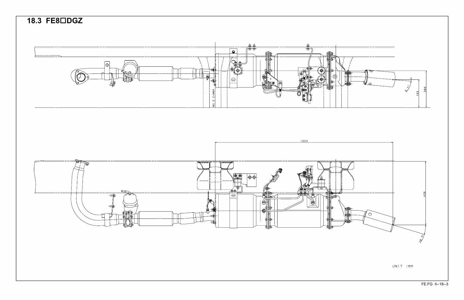
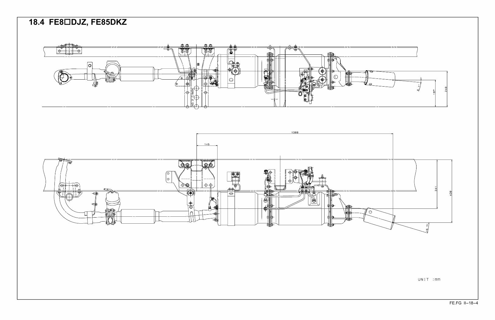
18.1 FE8!DDZ ........................................................................................................................................ II-18-1 18.2 FE8!DEZ ......................................................................................................................................... II-18-2 18.3 FE8!DGZ ........................................................................................................................................ II-18-3 18.4 FE8!DJZ, FE85DKZ ....................................................................................................................... II-18-4 18.5 FE84DHW ........................................................................................................................................ II-18-5 18.6 FG84DF6 .......................................................................................................................................... II-18-6
19. ELECTRIC CIRCUIT DIAGRAM ............................................................................................................... II-19-1
19.1 POWER, CHARGE AND GROUND CIRCUIT ................................................................................. II-19-1
POWER CIRCUIT ............................................................................................................... II-19-1
RESERVE POWER CIRCUIT ............................................................................................. II-19-13 BATTERY CHARGING CIRCUIT ........................................................................................ II-19-14 GROUND ............................................................................................................................. II-19-15 19.2 STARTING CIRCUIT ........................................................................................................................ II-19-32
ENGINE STARTING CIRCUIT ............................................................................................ II-19-32 ENGINE PREHEATING CIRCUIT ....................................................................................... II-19-34 19.3 LIGHTING CIRCUIT ......................................................................................................................... II-19-36
HEADLAMP CIRCUIT ......................................................................................................... II-19-36 DAYTIME RUNNING LIGHT CIRCUIT ............................................................................... II-19-37
TAIL, CLEARANCE AND LICENSE PLATE LAMPS CIRCUIT .......................................... II-19-39 STOP LAMP CIRCUIT ........................................................................................................ II-19-40 TURN SIGNAL AND HAZARD LAMP CIRCUIT ................................................................. II-19-42 BACKUP LAMP CIRCUIT ................................................................................................... II-19-43 CAB LAMP CIRCUIT ........................................................................................................... II-19-45 ILLUMINATION LAMP CIRCUIT ......................................................................................... II-19-46 IDENTIFICATION LAMP AND SIDE MARKER LAMP CIRCUIT ........................................ II-19-47 VAN BODY DOME LIGHT CIRCUIT ................................................................................... II-19-48 19.4 METER CLUSTER ........................................................................................................................... II-19-49
METER CLUSTER INTERNAL CIRCUIT ........................................................................... II-19-49 TACHOMETER CIRCUIT .................................................................................................... II-19-51 SPEEDOMETER CIRCUIT ................................................................................................. II-19-52 FUEL GAUGE CIRCUIT ...................................................................................................... II-19-53 WATER TEMPERATURE GAUGE CIRCUIT ..................................................................... II-19-54
19.5 INDICATOR AND WARNING LAMP CIRCUIT ................................................................................ II-19-55
PARKING BRAKE INDICATOR CIRCUIT .......................................................................... II-19-55 BRAKE WARNING CIRCUIT .............................................................................................. II-19-56 ENGINE OIL LEVEL WARNING CIRCUIT ......................................................................... II-19-58 ENGINE OIL PRESSURE WARNING CIRCUIT ................................................................. II-19-59 OVERHEATING WARNING CIRCUIT ................................................................................ II-19-60 BRAKE PAD WARNING CIRCUIT ...................................................................................... II-19-61
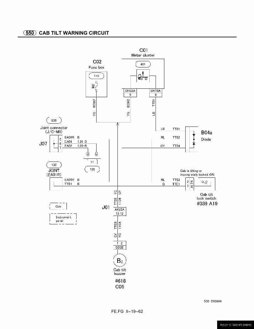
CAB TILT WARNING CIRCUIT ........................................................................................... II-19-62 FUEL FILTER WARNING CIRCUIT .................................................................................... II-19-63 19.6 CAB SIDE ELECTRICAL CIRCUIT .................................................................................................. II-19-64
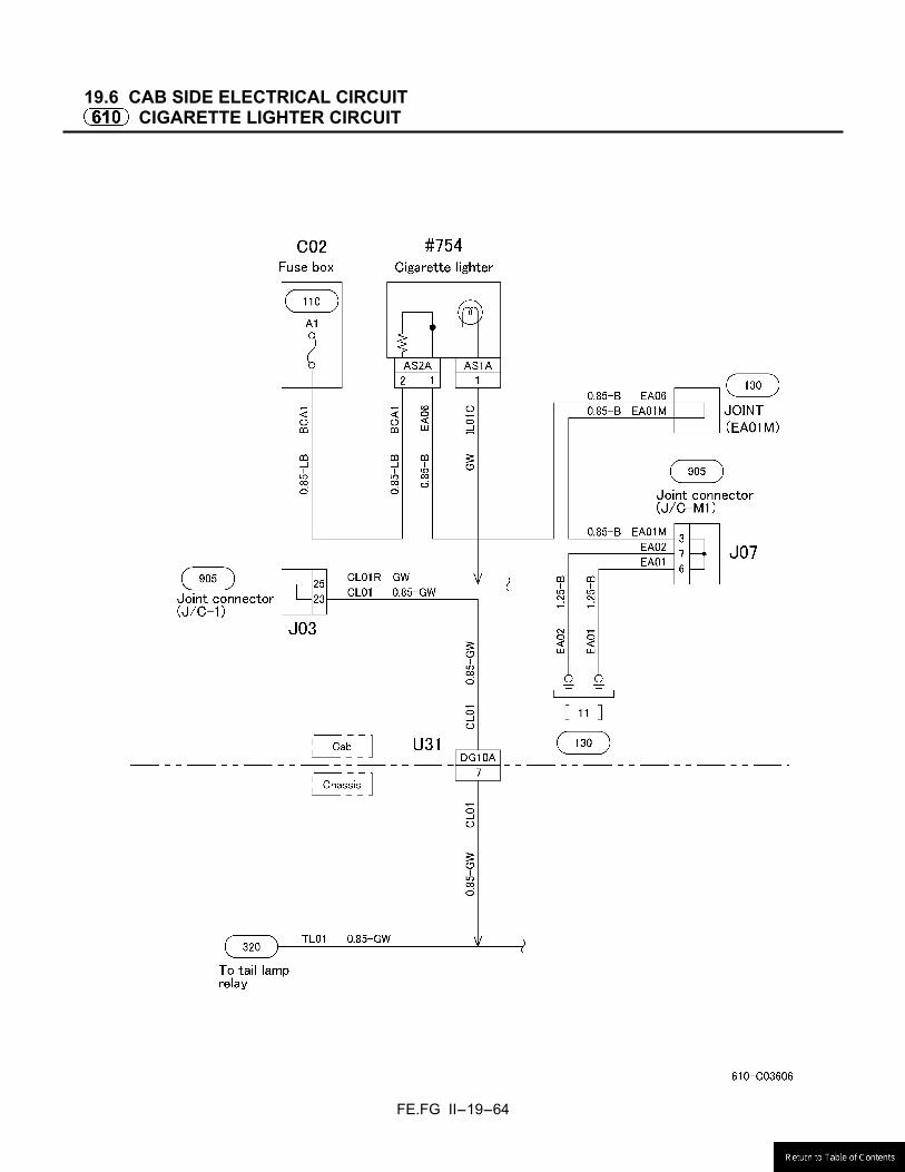
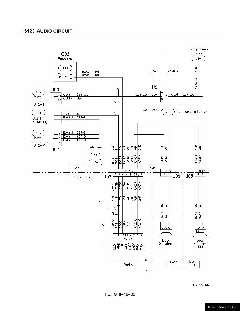
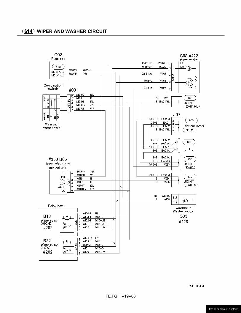
CIGARETTE LIGHTER CIRCUIT ........................................................................................ II-19-64 AUDIO CIRCUIT .................................................................................................................. II-19-65 WIPER AND WASHER CIRCUIT ........................................................................................ II-19-66 HORN CIRCUIT .................................................................................................................. II-19-67 AIR-CONDITIONER CIRCUIT ............................................................................................ II-19-68 POWER WINDOW AND CENTRAL DOOR LOCK CIRCUIT ............................................. II-19-70 MIRROR HEATER CIRCUIT ............................................................................................... II-19-71 19.7 CHASSIS SIDE ELECTRICAL CIRCUIT ......................................................................................... II-19-72
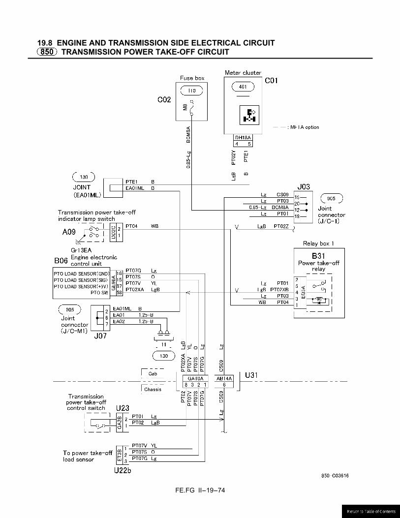
EXHAUST BRAKE CIRCUIT ............................................................................................... II-19-72 19.8 ENGINE AND TRANSMISSION SIDE ELECTRICAL CIRCUIT ...................................................... II-19-74
TRANSMISSION POWER TAKE-OFF CIRCUIT ................................................................ II-19-74 19.9 OTHER CIRCUIT ............................................................................................................................. II-19-75
JOINT CONNECTOR (J/C) ................................................................................................. II-19-75 DIAGNOSIS SWITCH AND MEMORY CLEAR SWITCH ................................................... II-19-79 COMMONRAIL SYSTEM CIRCUIT ................................................................................................. II-19-80 AUTOCRUISE SYSTEM CIRCUIT .................................................................................................. II-19-87 AUTOMATIC TRANSMISSION CIRCUIT ........................................................................................ II-19-89 ANTI-LOCK BRAKE SYSTEM CIRCUIT ......................................................................................... II-19-93
FE.FG II-1-1
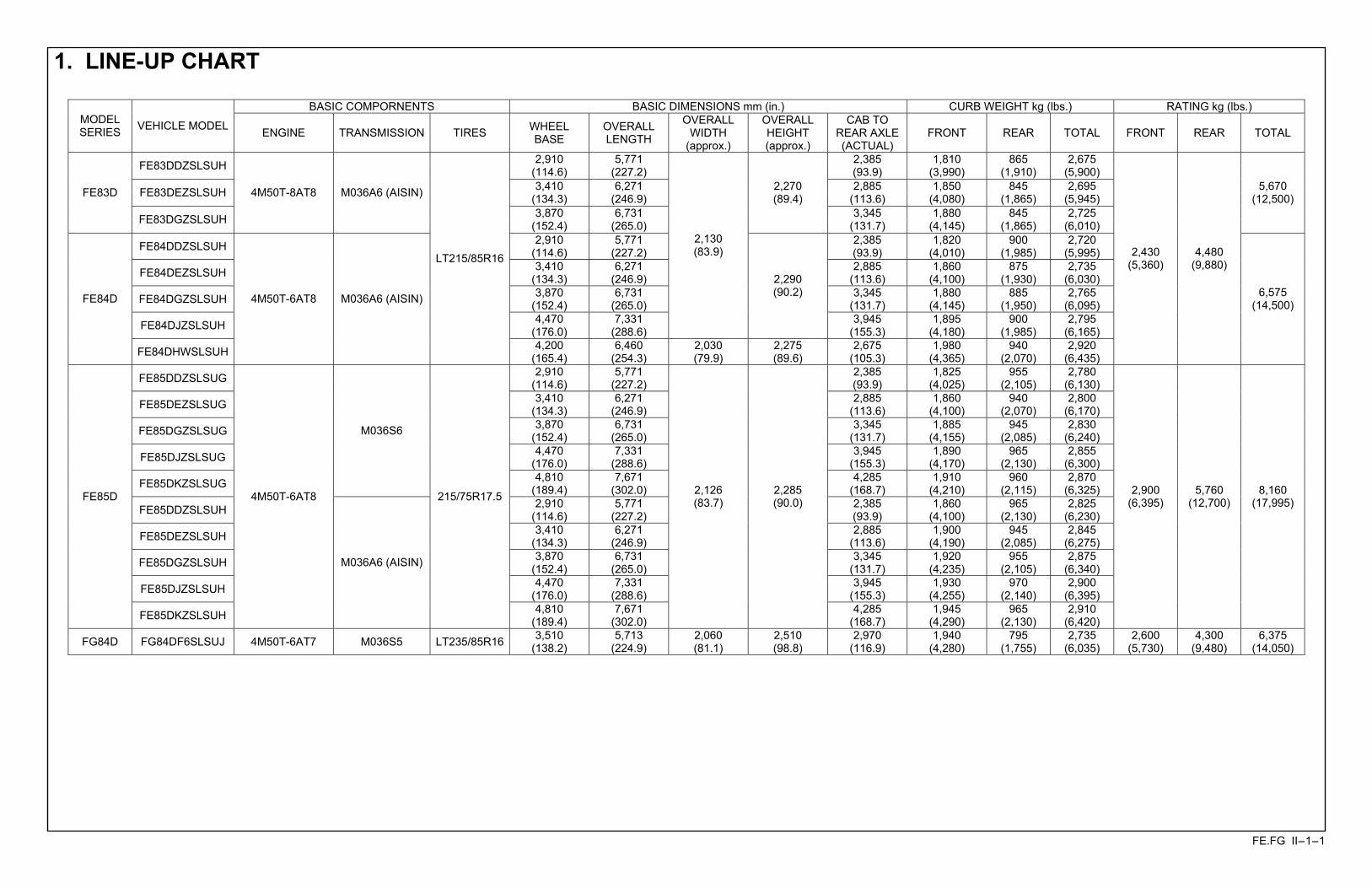
1. LINE-UP CHART
BASIC COMPORNENTS BASIC DIMENSIONS mm (in.) CURB WEIGHT kg (lbs.) RATING kg (lbs.) MODEL SERIES VEHICLE MODEL ENGINE TRANSMISSION TIRES WHEEL
BASE OVERALL LENGTH
OVERALL WIDTH
(approx.)
OVERALL HEIGHT (approx.)
CAB TO REAR AXLE (ACTUAL)
FRONT REAR TOTAL FRONT REAR TOTAL
FE83DDZSLSUH 2,910 (114.6)
5,771 (227.2)
2,385 (93.9)
1,810 (3,990)
865 (1,910)
2,675 (5,900)
FE83DEZSLSUH 3,410 (134.3)
6,271 (246.9)
2,885 (113.6)
1,850 (4,080)
845 (1,865)
2,695 (5,945) FE83D
FE83DGZSLSUH
4M50T-8AT8 M036A6 (AISIN)
3,870 (152.4)
6,731 (265.0)
2,270 (89.4)
3,345 (131.7)
1,880 (4,145)
845 (1,865)
2,725 (6,010)
5,670 (12,500)
FE84DDZSLSUH 2,910 (114.6)
5,771 (227.2)
2,385 (93.9)
1,820 (4,010)
900 (1,985)
2,720 (5,995)
FE84DEZSLSUH 3,410 (134.3)
6,271 (246.9)
2,885 (113.6)
1,860 (4,100)
875 (1,930)
2,735 (6,030)
FE84DGZSLSUH 3,870 (152.4)
6,731 (265.0)
3,345 (131.7)
1,880 (4,145)
885 (1,950)
2,765 (6,095)
FE84DJZSLSUH 4,470 (176.0)
7,331 (288.6)
2,130 (83.9)
2,290 (90.2)
3,945 (155.3)
1,895 (4,180)
900 (1,985)
2,795 (6,165)
FE84D
FE84DHWSLSUH
4M50T-6AT8 M036A6 (AISIN)
LT215/85R16
4,200 (165.4)
6,460 (254.3)
2,030 (79.9)
2,275 (89.6)
2,675 (105.3)
1,980 (4,365)
940 (2,070)
2,920 (6,435)
2,430 (5,360)
4,480 (9,880)
6,575 (14,500)
FE85DDZSLSUG 2,910 (114.6)
5,771 (227.2)
2,385 (93.9)
1,825 (4,025)
955 (2,105)
2,780 (6,130)
FE85DEZSLSUG 3,410 (134.3)
6,271 (246.9)
2,885 (113.6)
1,860 (4,100)
940 (2,070)
2,800 (6,170)
FE85DGZSLSUG 3,870 (152.4)
6,731 (265.0)
3,345 (131.7)
1,885 (4,155)
945 (2,085)
2,830 (6,240)
FE85DJZSLSUG 4,470 (176.0)
7,331 (288.6)
3,945 (155.3)
1,890 (4,170)
965 (2,130)
2,855 (6,300)
FE85DKZSLSUG
M036S6
4,810 (189.4)
7,671 (302.0)
4,285 (168.7)
1,910 (4,210)
960 (2,115)
2,870 (6,325)
FE85DDZSLSUH 2,910 (114.6)
5,771 (227.2)
2,385 (93.9)
1,860 (4,100)
965 (2,130)
2,825 (6,230)
FE85DEZSLSUH 3,410 (134.3)
6,271 (246.9)
2,885 (113.6)
1,900 (4,190)
945 (2,085)
2,845 (6,275)
FE85DGZSLSUH 3,870 (152.4)
6,731 (265.0)
3,345 (131.7)
1,920 (4,235)
955 (2,105)
2,875 (6,340)
FE85DJZSLSUH 4,470 (176.0)
7,331 (288.6)
3,945 (155.3)
1,930 (4,255)
970 (2,140)
2,900 (6,395)
FE85D
FE85DKZSLSUH
4M50T-6AT8
M036A6 (AISIN)
215/75R17.5
4,810 (189.4)
7,671 (302.0)
2,126 (83.7)
2,285 (90.0)
4,285 (168.7)
1,945 (4,290)
965 (2,130)
2,910 (6,420)
2,900 (6,395)
5,760 (12,700)
8,160 (17,995)
FG84D FG84DF6SLSUJ 4M50T-6AT7 M036S5 LT235/85R16 3,510 (138.2)
5,713 (224.9)
2,060 (81.1)
2,510 (98.8)
2,970 (116.9)
1,940 (4,280)
795 (1,755)
2,735 (6,035)
2,600 (5,730)
4,300 (9,480)
6,375 (14,050)
FE.FG II-2-1
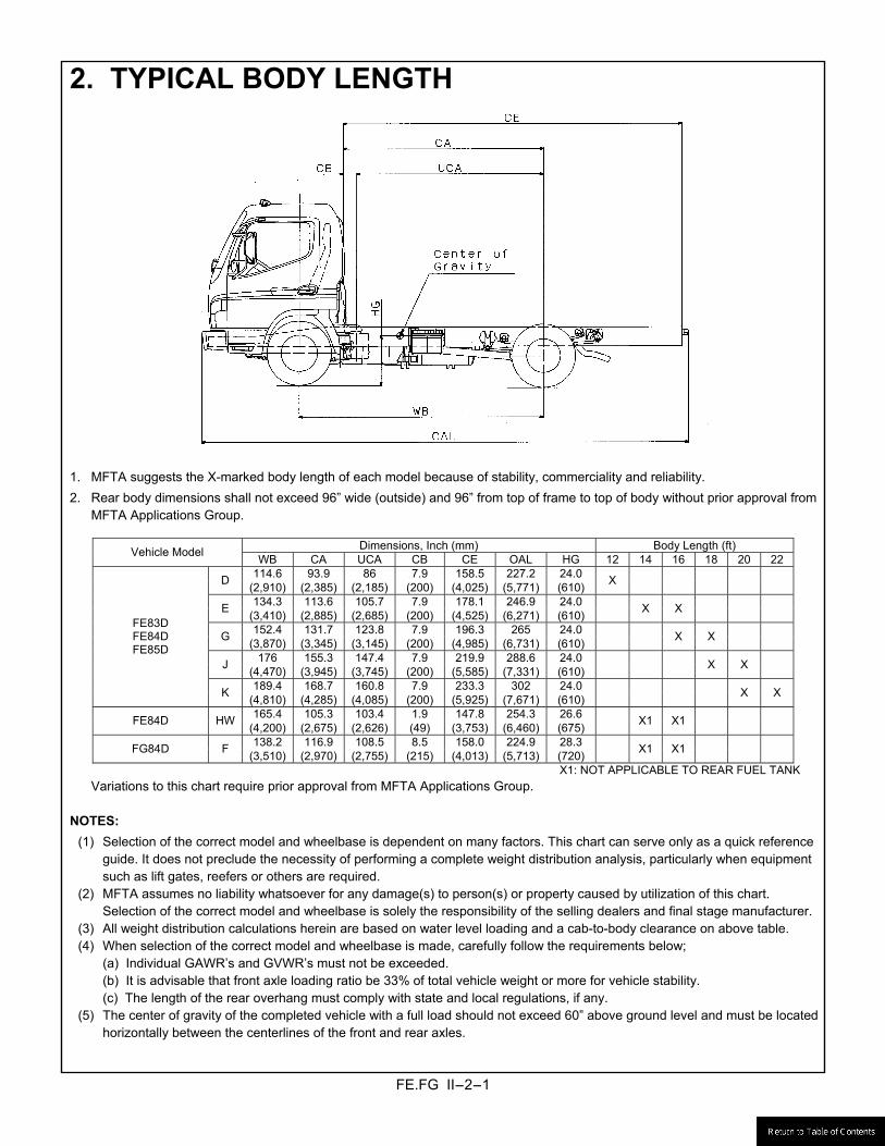
2. TYPICAL BODY LENGTH
1. MFTA suggests the X-marked body length of each model because of stability, commerciality and reliability. 2. Rear body dimensions shall not exceed 96� wide (outside) and 96� from top of frame to top of body without prior approval from
MFTA Applications Group.
Dimensions, Inch (mm) Body Length (ft) Vehicle Model WB CA UCA CB CE OAL HG 12 14 16 18 20 22114.6 93.9 86 7.9 158.5 227.2 24.0 D (2,910) (2,385) (2,185) (200) (4,025) (5,771) (610) X
134.3 113.6 105.7 7.9 178.1 246.9 24.0 E (3,410) (2,885) (2,685) (200) (4,525) (6,271) (610) X X
152.4 131.7 123.8 7.9 196.3 265 24.0 G (3,870) (3,345) (3,145) (200) (4,985) (6,731) (610) X X
176 155.3 147.4 7.9 219.9 288.6 24.0 J (4,470) (3,945) (3,745) (200) (5,585) (7,331) (610) X X
189.4 168.7 160.8 7.9 233.3 302 24.0
FE83D FE84D FE85D
K (4,810) (4,285) (4,085) (200) (5,925) (7,671) (610) X X
165.4 105.3 103.4 1.9 147.8 254.3 26.6 FE84D HW (4,200) (2,675) (2,626) (49) (3,753) (6,460) (675) X1 X1
138.2 116.9 108.5 8.5 158.0 224.9 28.3 FG84D F (3,510) (2,970) (2,755) (215) (4,013) (5,713) (720) X1 X1
X1: NOT APPLICABLE TO REAR FUEL TANK Variations to this chart require prior approval from MFTA Applications Group.
NOTES:
(1) Selection of the correct model and wheelbase is dependent on many factors. This chart can serve only as a quick reference guide. It does not preclude the necessity of performing a complete weight distribution analysis, particularly when equipment such as lift gates, reefers or others are required.
(2) MFTA assumes no liability whatsoever for any damage(s) to person(s) or property caused by utilization of this chart. Selection of the correct model and wheelbase is solely the responsibility of the selling dealers and final stage manufacturer.
(3) All weight distribution calculations herein are based on water level loading and a cab-to-body clearance on above table. (4) When selection of the correct model and wheelbase is made, carefully follow the requirements below;
(a) Individual GAWR�s and GVWR�s must not be exceeded. (b) It is advisable that front axle loading ratio be 33% of total vehicle weight or more for vehicle stability. (c) The length of the rear overhang must comply with state and local regulations, if any.
(5) The center of gravity of the completed vehicle with a full load should not exceed 60� above ground level and must be located horizontally between the centerlines of the front and rear axles.
FE.FG II-3-1
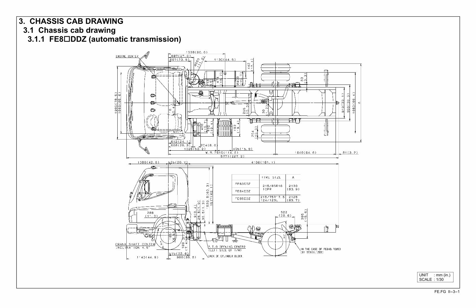
3. CHASSIS CAB DRAWING 3.1 Chassis cab drawing
3.1.1 FE8!DDZ (automatic transmission)
UNIT : mm (in.)SCALE : 1/30

FE.FG II-3-2
3.1.2 FE85DDZ (manual transmission)
UNIT : mm (in.)SCALE : 1/30
FE.FG II-3-3
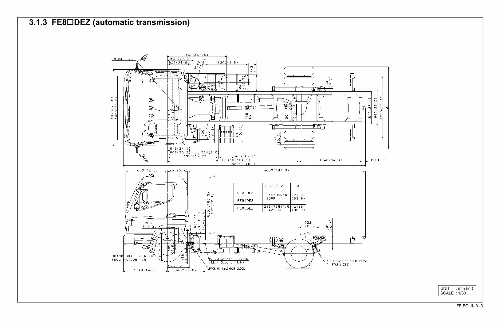
3.1.3 FE8!DEZ (automatic transmission)
UNIT : mm (in.)SCALE : 1/30

FE.FG II-3-4
3.1.4 FE85DEZ (manual transmission)
UNIT : mm (in.)SCALE : 1/30

FE.FG II-3-5
3.1.5 FE8!DGZ (automatic transmission)
UNIT : mm (in.)SCALE : 1/30

FE.FG II-3-6
3.1.6 FE85DGZ (manual transmission)
UNIT : mm (in.)SCALE : 1/30
FE.FG II-3-7
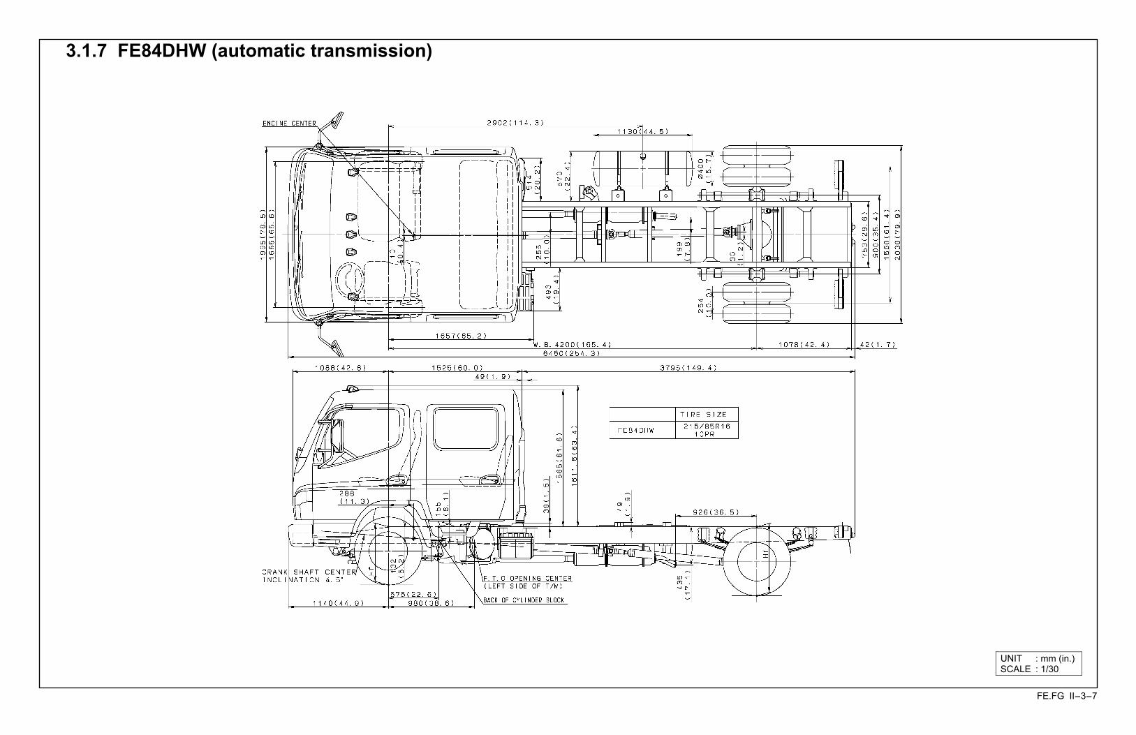
3.1.7 FE84DHW (automatic transmission)
UNIT : mm (in.)SCALE : 1/30

FE.FG II-3-8
3.1.8 FE8!DJZ (automatic transmission)
UNIT : mm (in.)SCALE : 1/30
FE.FG II-3-9
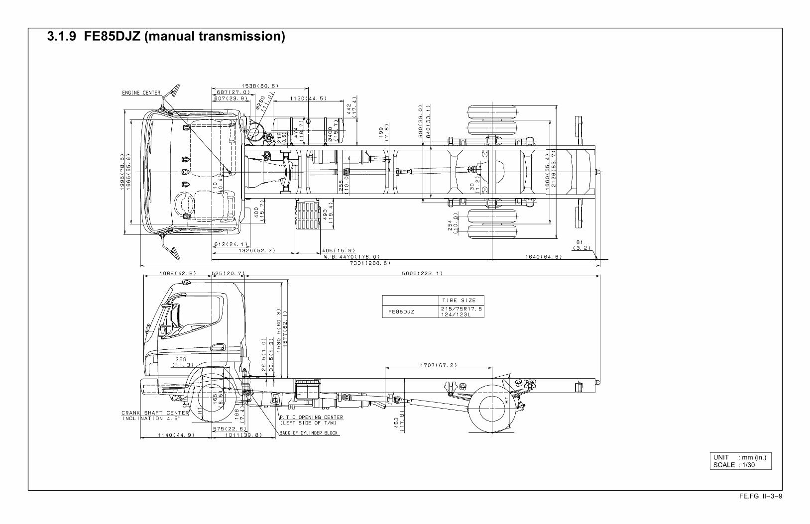
3.1.9 FE85DJZ (manual transmission)
UNIT : mm (in.)SCALE : 1/30
FE.FG II-3-10
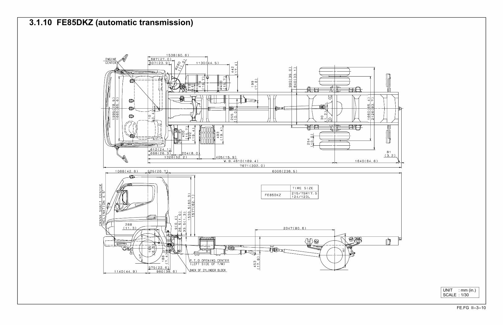
3.1.10 FE85DKZ (automatic transmission)
UNIT : mm (in.)SCALE : 1/30
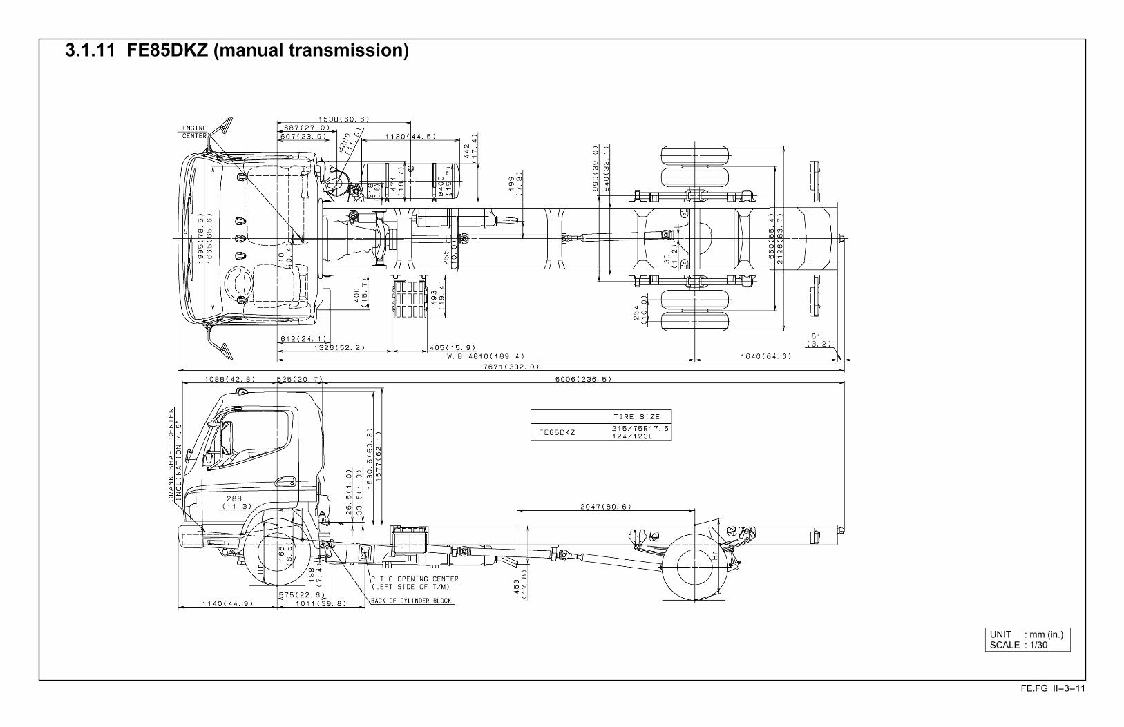
FE.FG II-3-11
3.1.11 FE85DKZ (manual transmission)
UNIT : mm (in.)SCALE : 1/30
FE.FG II-3-12
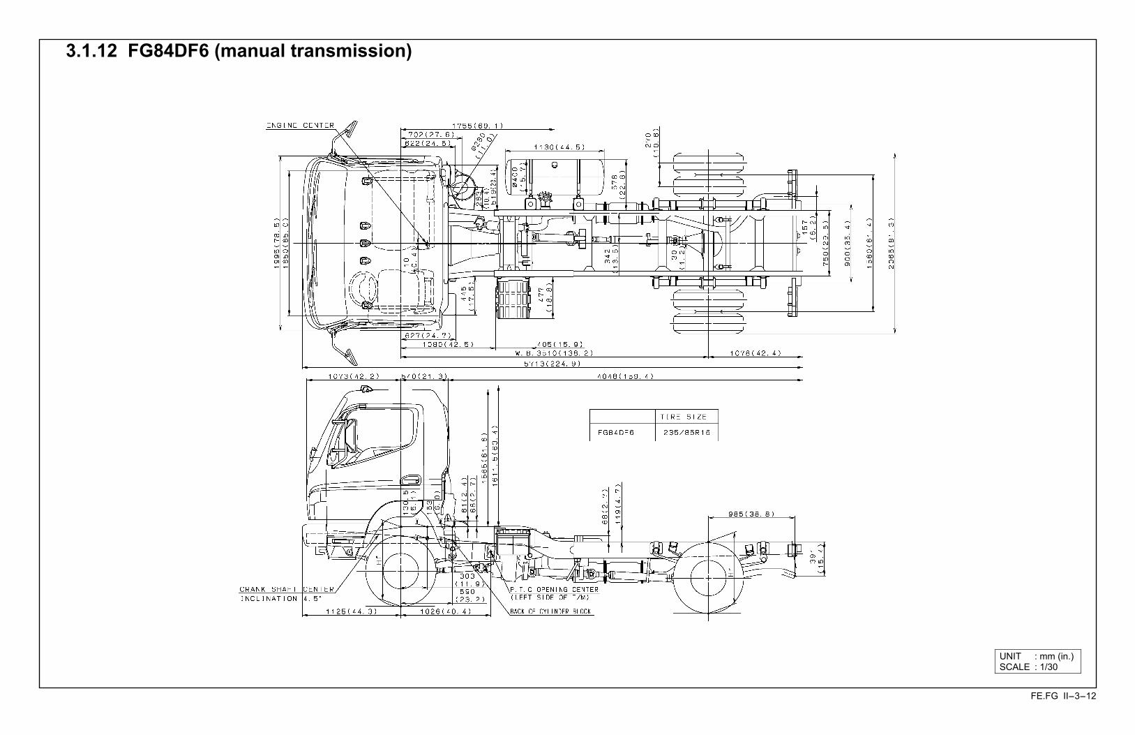
3.1.12 FG84DF6 (manual transmission)
UNIT : mm (in.)SCALE : 1/30
FE.FG II-3-13
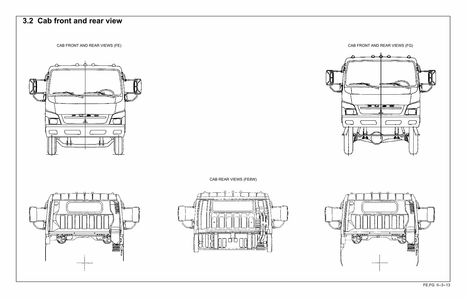
3.2 Cab front and rear view
CAB FRONT AND REAR VIEWS (FE)
CAB REAR VIEWS (FE8W)
CAB FRONT AND REAR VIEWS (FG)
FE.FG II-4-1
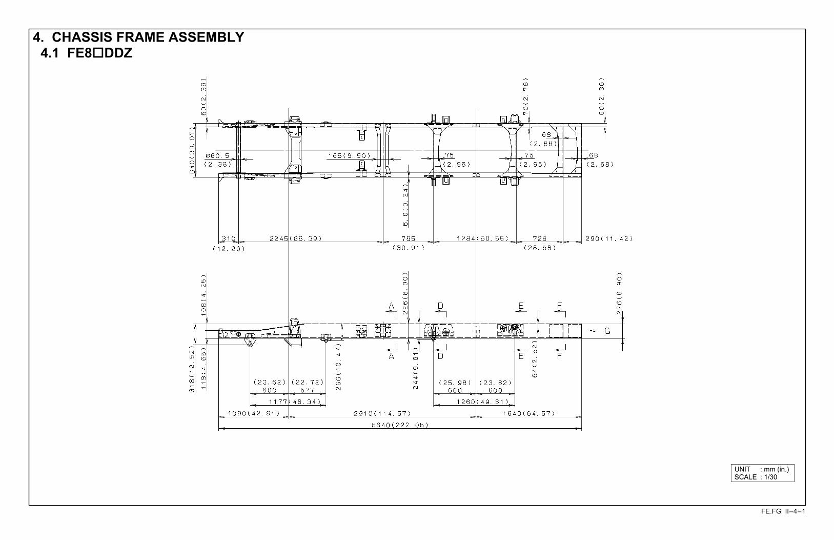
4. CHASSIS FRAME ASSEMBLY 4.1 FE8!DDZ
UNIT : mm (in.)SCALE : 1/30

FE.FG II-4-2
4.2 FE8!DEZ
UNIT : mm (in.)SCALE : 1/30
FE.FG II-4-3
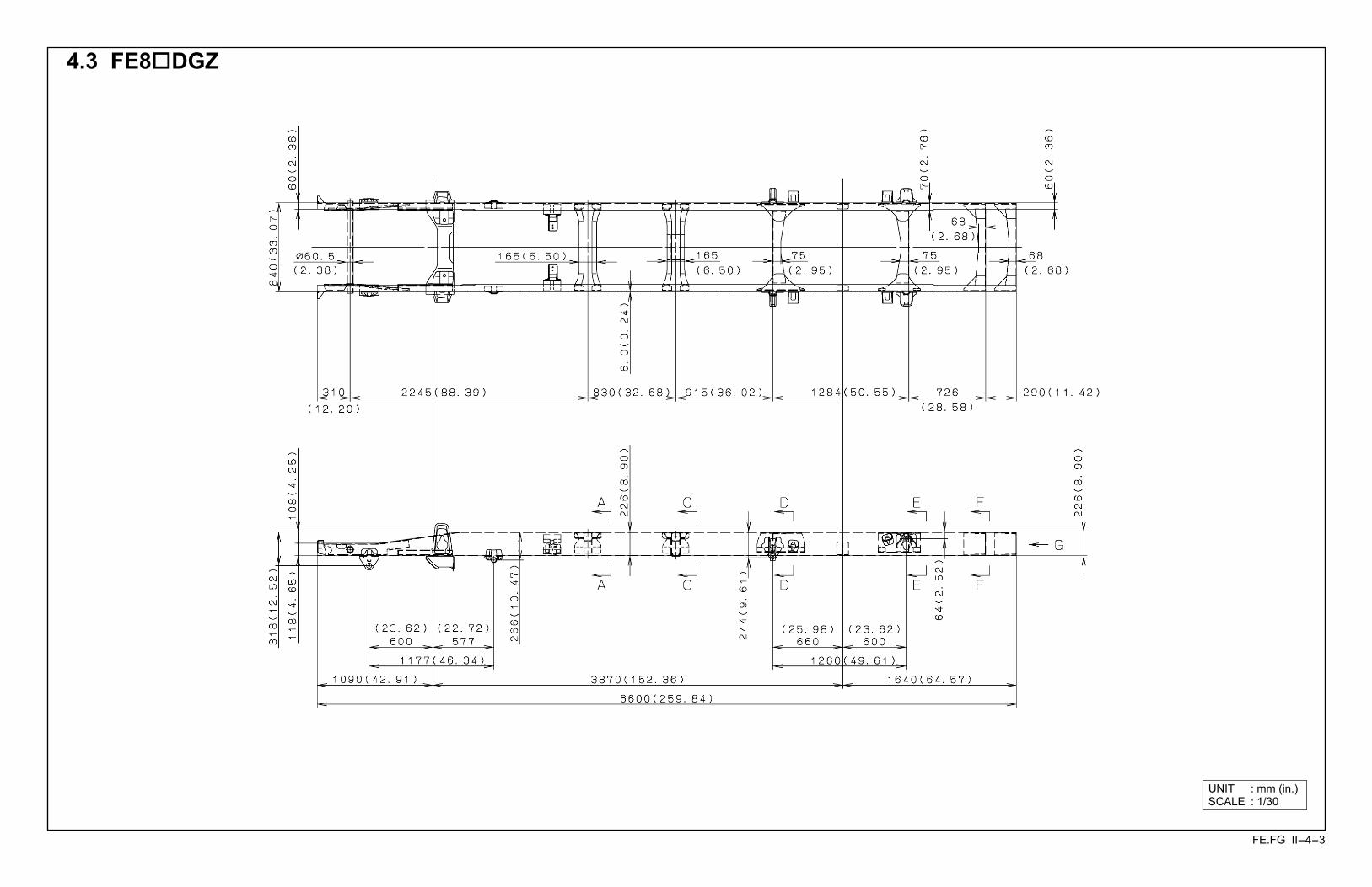
4.3 FE8!DGZ
UNIT : mm (in.)SCALE : 1/30

FE.FG II-4-4
4.4 FE8!DJZ
UNIT : mm (in.)SCALE : 1/30
FE.FG II-4-5
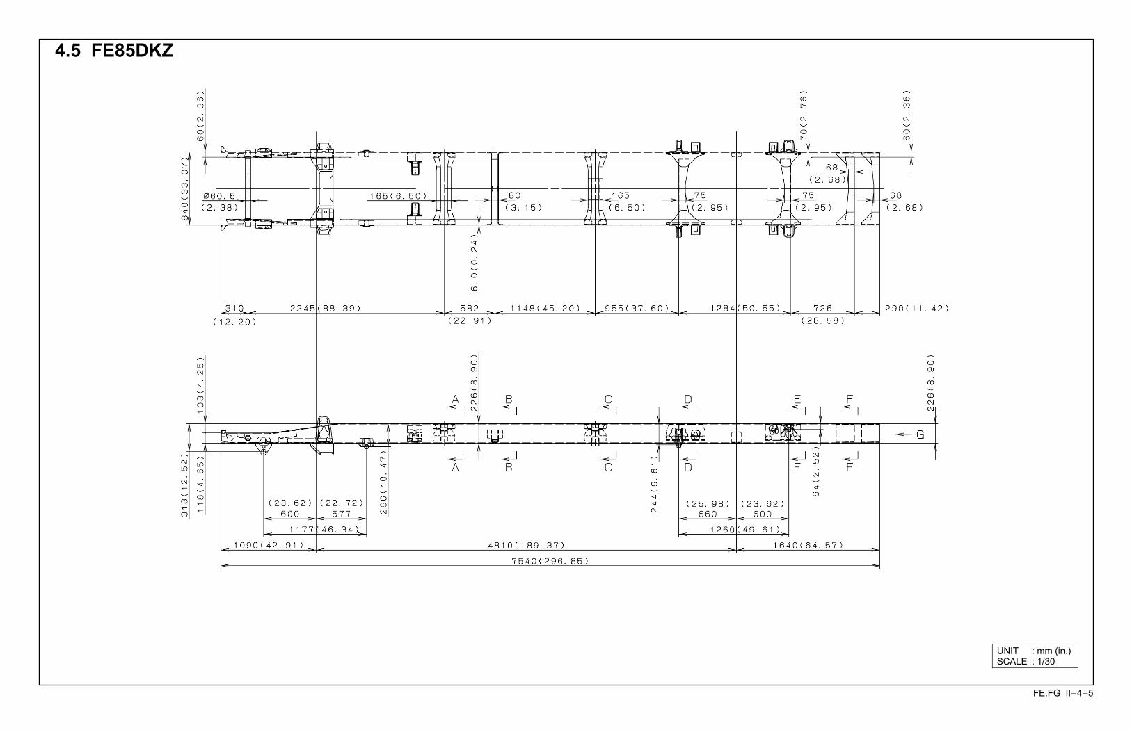
4.5 FE85DKZ
UNIT : mm (in.)SCALE : 1/30
FE.FG II-4-6
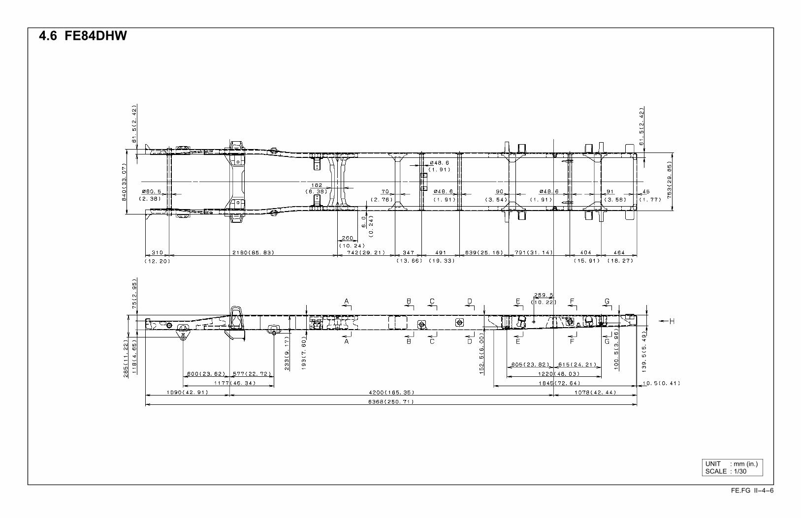
4.6 FE84DHW
UNIT : mm (in.)SCALE : 1/30

FE.FG II-4-7
4.7 FG84DF6
UNIT : mm (in.)SCALE : 1/30

FE.FG II-5-1
5. CROSSMEMBER REAR VIEW 5.1 FE Series (Except FE84DHW)
FE.FG II-5-2
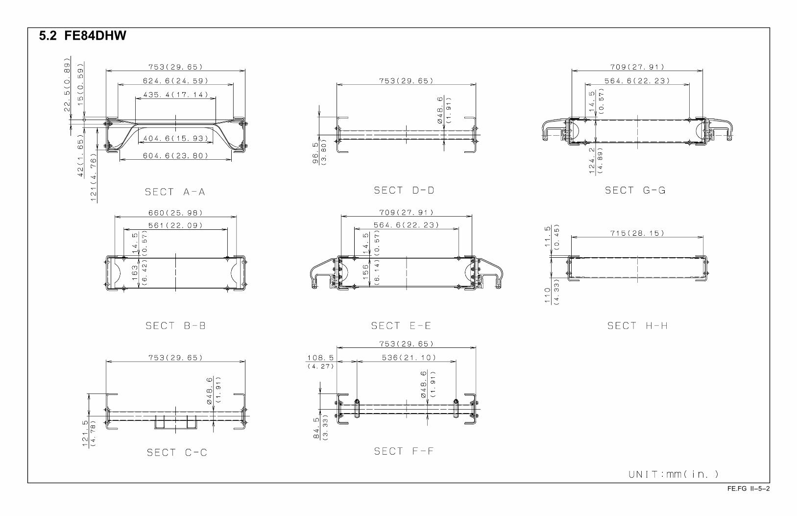
5.2 FE84DHW

FE.FG II-5-3
5.3 FG Series
FE.FG II-6-1
6.
FR
AM
E SE
CTI
ON
MO
DU
LUS
DIA
GR
AM
S 6.
1 F
E8!
DD
Z
FE.FG II-6-2
6.2
FE8
!D
EZ
FE.FG II-6-3
6.
3 F
E8!
DG
Z
FE.FG II-6-4
6.
4 F
E8!
DJZ
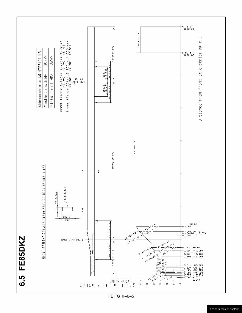
FE.FG II-6-5
6.5
FE8
5DK
Z

FE.FG II-6-6
6.6
FE8
4DH
W

FE.FG II-6-7
6.7
FG
84D
F6

FE.FG II-7-1
7. FRAME HEIGHT 7.1 Tire radius
(Ground to top of Frame at Front & Rear Axle center) Calculating the formulas
Hf = hf + Rf (Frame height, Front) Hr = hr + Rr (Frame height, Rear)
hf : Distance from top to front wheel center (see section 9 : Front and Rear springs) hr : Distance from top to rear wheel center (see section 9 : Front and Rear springs) Rf, Rr : Tire radius (See following Tire chart following.)
FE.FG II-7-2
7.2
Fro
nt a
nd re
ar s
prin
gs
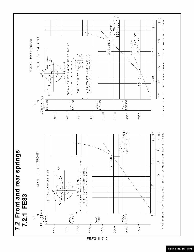
7.2.
1 F
E83
(F
RO
NT)
(RE
AR
)
FE.FG II-7-3
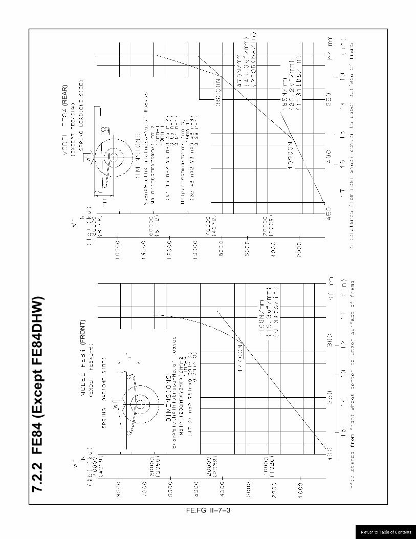
7.2.
2 F
E84
(Exc
ept F
E84D
HW
)
(F
RO
NT)
(RE
AR
)

FE.FG II-7-4
7.2.
3 F
E84D
HW
(F
RO
NT)
(R
EA
R)
FE.FG II-7-5
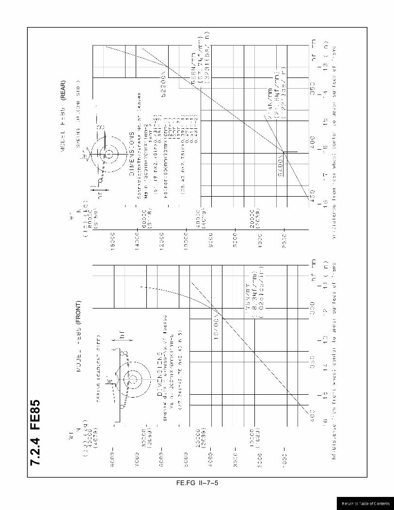
7.2.
4 F
E85
(FR
ON
T)
(RE
AR
)
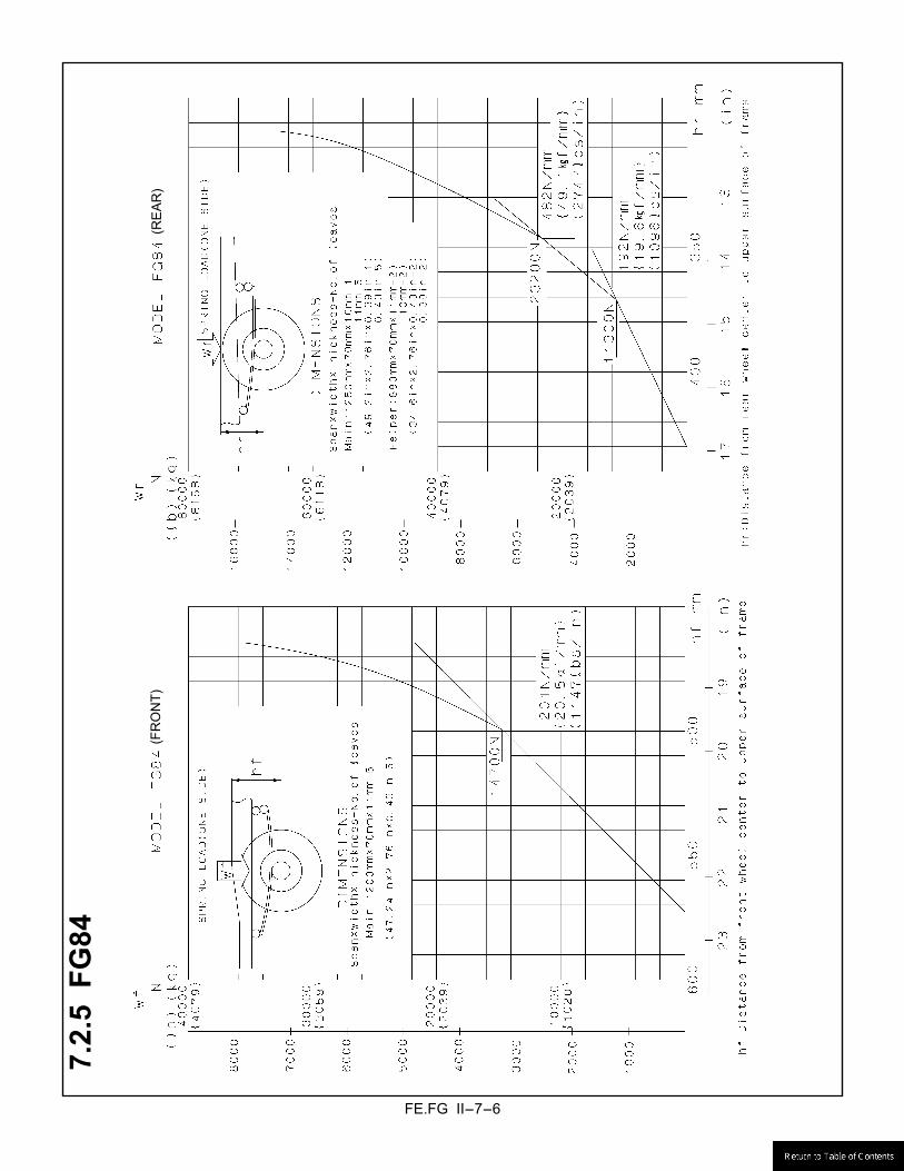
FE.FG II-7-6
7.2.
5 F
G84
(RE
AR
) (F
RO
NT)
(R
EA
R)

FE.FG II-7-7
7.3 Vehicle�s sprung weight
SPRUNG WEIGHT kg (Ibs) VEHICLE MODEL FRONT REAR TOTAL FE83DDZSLSUH FE84DDZSLSUH
1510 (3,330)
340 (750)
1850 (4,080)
FE83DEZSLSUH FE84DEZSLSUH
1550 (3,415)
315 (685)
1865 (4,100)
FE83DGZSLSUH FE84DGZSLSUH
1575 (3,470)
320 (710)
1895 (4,180)
FE84DHWSLSUH 1670 (3,680)
405 (895)
2075 (4,575)
FE84DJZSLSUH 1580 (3,485)
340 (750)
1920 (4,235)
FE85DDZSLSUG 1480 (3,265)
325 (715)
1805 (3,980)
FE85DEZSLSUG 1520 (3,350)
300 (660)
1820 (4,010)
FE85DGZSLSUG 1540 (3,395)
310 (685)
1850 (4,080)
FE85DJZSLSUG 1550 (3,415)
330 (730)
1880 (4,145)
FE85DKZSLSUG 1565 (3,450)
325 (720)
1890 (4,170)
FE85DDZSLSUH 1515 (3,340)
335 (740)
1850 (4,080)
FE85DEZSLSUH 1550 (3,415)
315 (695)
1865 (4,110)
FE85DGZSLSUH 1575 (3,470)
320 (710)
1895 (4,180)
FE85DJZSLSUH 1590 (3,505)
335 (740)
1925 (4,245)
FE85DKZSLSUH 1600 (3,525)
335 (740)
1935 (4,265)
FG84DF6SLSUJ 1535 (3,385)
300 (660)
1835 (4,045)
FE.FG II-8-1
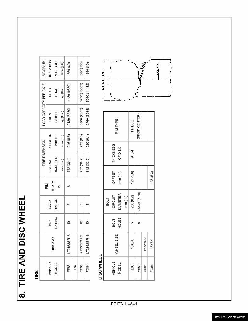
8. T
IRE
AN
D D
ISC
WH
EEL
TI
RE
TIR
E D
IME
NS
ION
LO
AD
CA
PA
CIT
Y P
ER
AX
LE
VE
HIC
LE
MO
DE
L TI
RE
SIZ
E
PLY
RA
TIN
G
LOA
D
RA
NG
E
RIM
WID
TH
in.
OV
ER
ALL
DIA
ME
TER
mm
(in.
)
SE
CTI
ON
WID
TH
mm
(in.
)
FRO
NT
SIN
GLE
kg (l
bs.)
RE
AR
DU
AL
kg (l
bs.)
MA
XIM
UM
INFL
ATI
ON
PR
ES
SU
RE
kPa
(psi
)
FE83
LT
215/
85R
16
10
E
6 77
2 (3
0.4)
21
6 (8
.5)
2430
(536
0)44
80 (9
880)
550
(80)
FE84
FE85
21
5/75
R17
.5
12
F
767
(30.
2)
212
(8.3
) 32
00 (7
055)
6200
(136
69)
690
(100
)
FG84
LT
235/
85R
16
10
E
81
2 (3
2.0)
23
0 (9
.1)
2760
(608
4)50
40 (1
1112
)55
0 (8
0)
D
ISC
WH
EEL
VE
HIC
LE
MO
DE
L W
HE
EL
SIZ
E
BO
LT
HO
LES
BO
LT
CIR
CU
IT
DIA
ME
TER
mm
(in.
)
OFF
SE
T
mm
(in.
)
THIC
KN
ES
S
OF
DIS
C
RIM
TYP
E
FE83
16
X6K
5
208
(8.2
) 12
7 (5
.0)
9 (0
.4)
FE84
6 22
2.25
(8.7
5)
FE85
17
.5X
6.00
FG84
16
X6K
13
5 (5
.3)
1 P
IEC
E
(DR
OP
CE
NTE
R)

FE.FG II-9-1
9. FRONT AXLE
FRONT AXLE VEHICLE
MODEL MODEL CAPACITY
kg (lbs.)
TIRE SIZE FT
mm (in.)
SC
mm (in.)
FH
mm (in.)
FE83 F200T 2400 (5290) LT215/85R16 (16x6K) 1665 (65.55) 807 (31.77) 177 (6.97)
FE84 F300T 2500 (5510)
FG84 F200TW 2600 (5730) LT235/85R16 (16x6K) 1650 (65.00) 807 (31.77) 156.5 (6.16)
FE85 F350T 2900 (6390) 215/75R17.5 (17.5x6.00) 1665 (65.55) 807 (31.77) 177 (6.97)
DEFINITIONS
FT : Front tread SC : Spring to spring distance FH : Distance between the center line of tire and the bottom of front axle FC : Front axle clearance Minimum clearance between the front axle and the ground-line
TIRE LOADED RADIUS : See section 7: FRAME HEIGHT �Tire radius� (PAGE II-7-1)
Formula for calculating front axle clearance FC = Tire loaded Radius - FH
FE
FG
FE.FG II-10-1
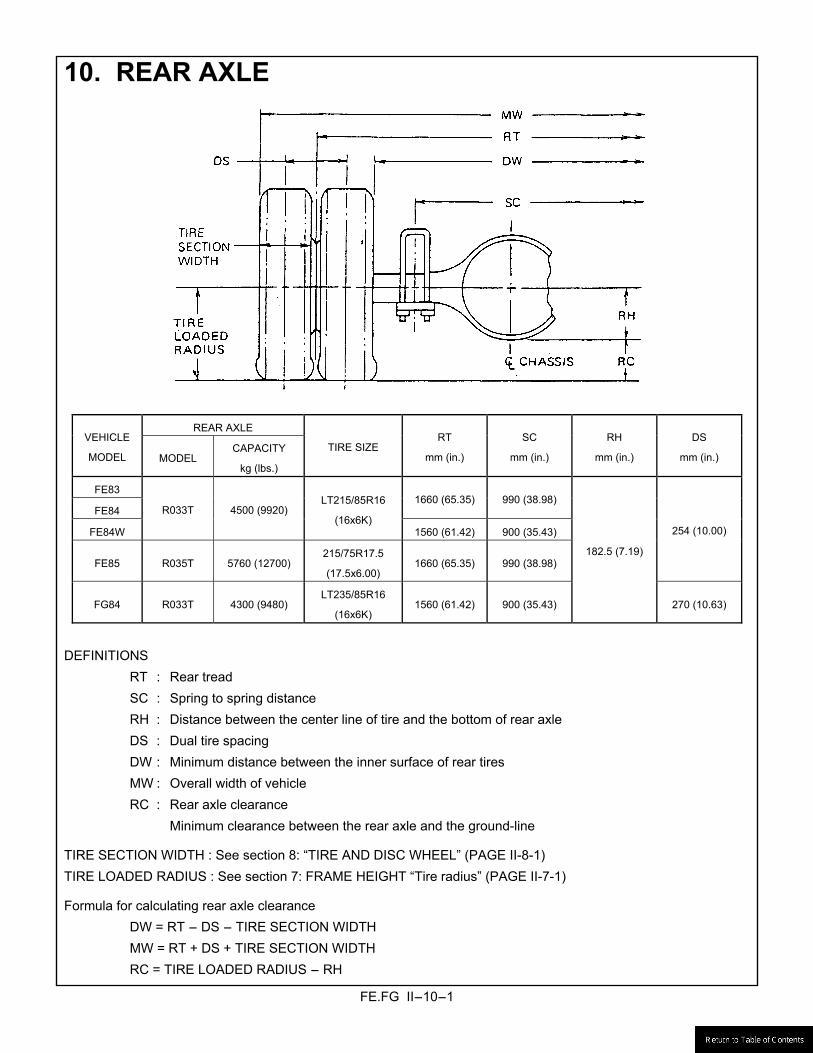
10. REAR AXLE
REAR AXLE VEHICLE
MODEL MODEL CAPACITY
kg (lbs.)
TIRE SIZE RT
mm (in.)
SC
mm (in.)
RH
mm (in.)
DS
mm (in.)
FE83
FE84 1660 (65.35) 990 (38.98)
FE84W
R033T 4500 (9920) LT215/85R16
(16x6K) 1560 (61.42) 900 (35.43)
FE85 R035T 5760 (12700) 215/75R17.5
(17.5x6.00) 1660 (65.35) 990 (38.98)
254 (10.00)
FG84 R033T 4300 (9480) LT235/85R16
(16x6K) 1560 (61.42) 900 (35.43)
182.5 (7.19)
270 (10.63)
DEFINITIONS
RT : Rear tread SC : Spring to spring distance RH : Distance between the center line of tire and the bottom of rear axle DS : Dual tire spacing DW : Minimum distance between the inner surface of rear tires MW : Overall width of vehicle RC : Rear axle clearance Minimum clearance between the rear axle and the ground-line
TIRE SECTION WIDTH : See section 8: “TIRE AND DISC WHEEL” (PAGE II-8-1) TIRE LOADED RADIUS : See section 7: FRAME HEIGHT “Tire radius” (PAGE II-7-1)
Formula for calculating rear axle clearance DW = RT - DS - TIRE SECTION WIDTH MW = RT + DS + TIRE SECTION WIDTH RC = TIRE LOADED RADIUS - RH
FE.FG II-11-1
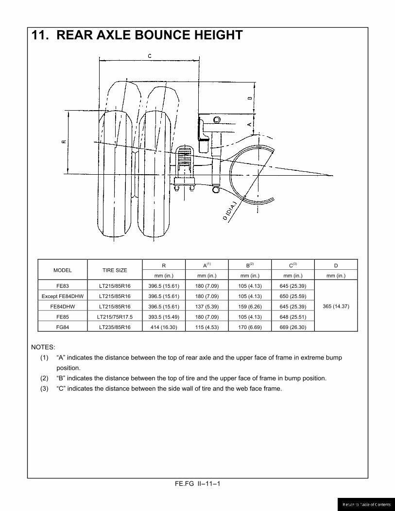
11. REAR AXLE BOUNCE HEIGHT
R A(1) B(2) C(3) D MODEL TIRE SIZE
mm (in.) mm (in.) mm (in.) mm (in.) mm (in.)
FE83 LT215/85R16 396.5 (15.61) 180 (7.09) 105 (4.13) 645 (25.39)
Except FE84DHW LT215/85R16 396.5 (15.61) 180 (7.09) 105 (4.13) 650 (25.59)
FE84DHW LT215/85R16 396.5 (15.61) 137 (5.39) 159 (6.26) 645 (25.39)
FE85 LT215/75R17.5 393.5 (15.49) 180 (7.09) 105 (4.13) 648 (25.51)
FG84 LT235/85R16 414 (16.30) 115 (4.53) 170 (6.69) 669 (26.30)
365 (14.37)
NOTES:
(1) �A� indicates the distance between the top of rear axle and the upper face of frame in extreme bump position.
(2) �B� indicates the distance between the top of tire and the upper face of frame in bump position. (3) �C� indicates the distance between the side wall of tire and the web face frame.

FE.FG II-12-1
12. FUEL TANK 12.1 FE Series <Except FE84DHW>
UNIT : mm
FE.FG II-12-2
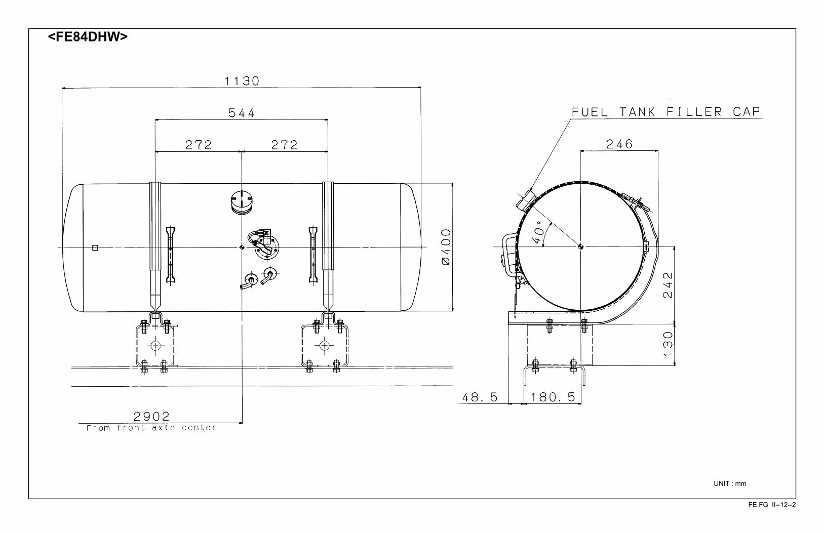
<FE84DHW>
UNIT : mm
FE.FG II-12-3
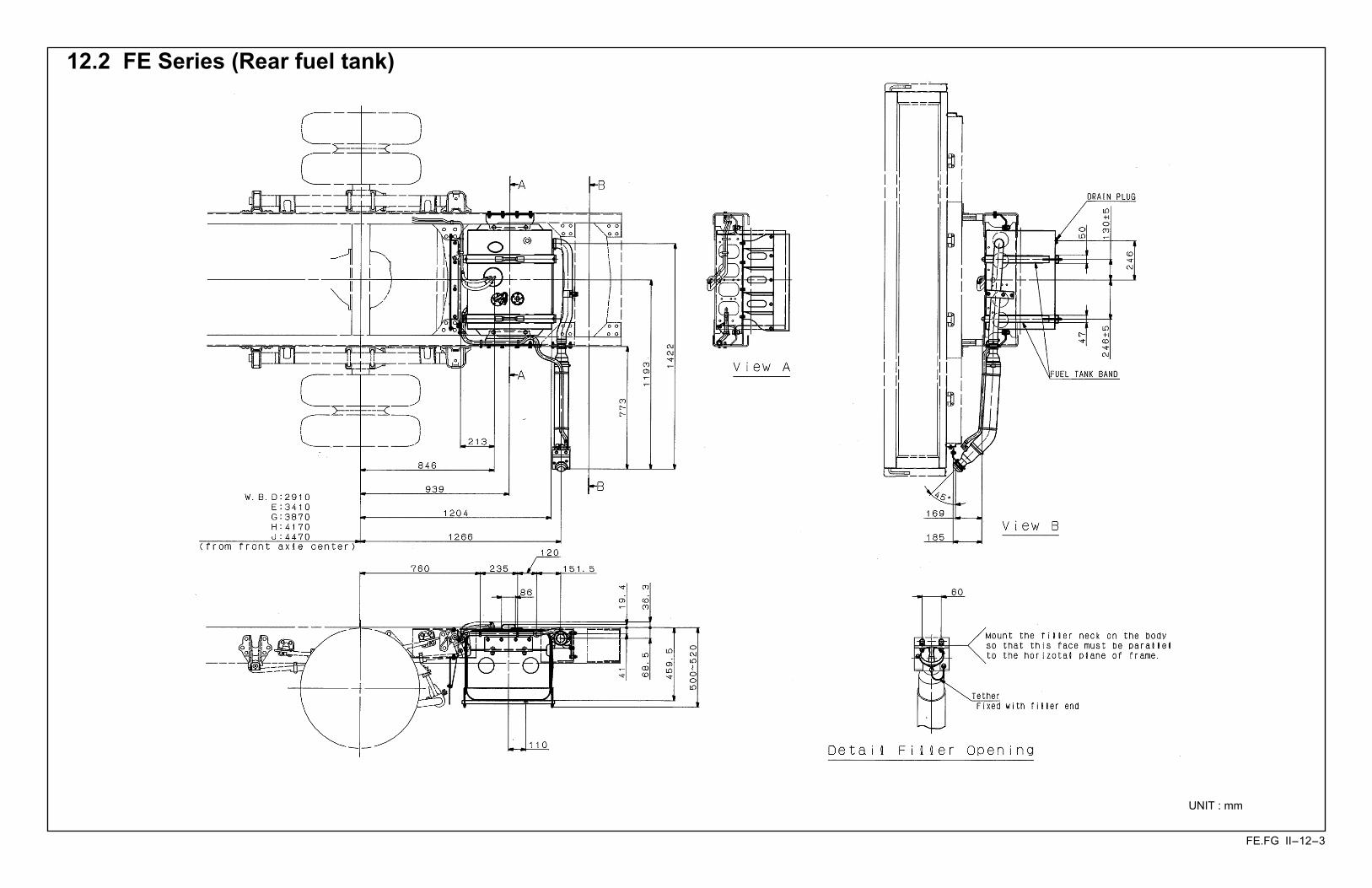
12.2 FE Series (Rear fuel tank)
UNIT : mm
FE.FG II-12-4
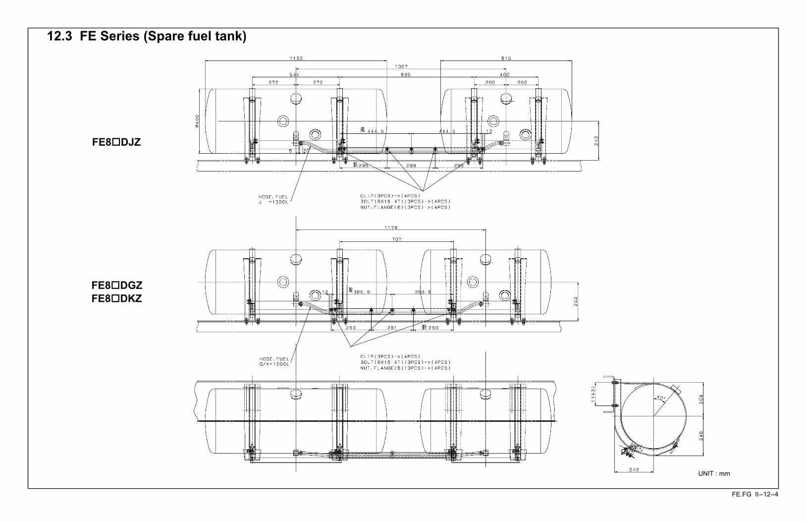
12.3 FE Series (Spare fuel tank)
FE8 DJZ
FE8 DGZ FE8 DKZ
UNIT : mm

FE.FG II-12-5
12.4 FG Series
UNIT : mm
FE.FG II-13-1
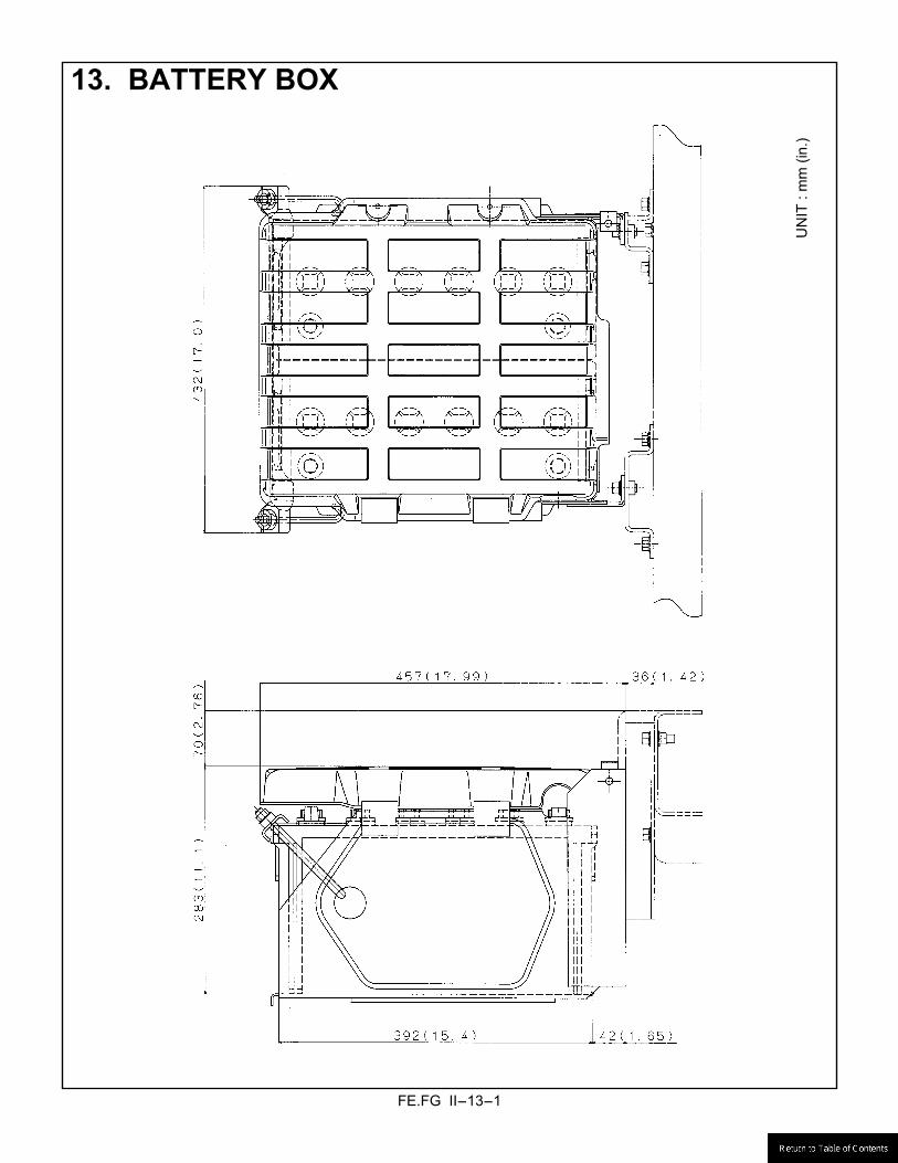
13. BATTERY BOX
UN
IT :
mm
(in.
)
FE.FG II-14-1
FE84
DH
W
FG84
D
FE8 *
**Z
14.
LIC
ENSE
PLA
TE L
AM
P
FE.FG II-15-1
15. REAR COMBINATION LAMP
FE.FG II-16-1
16.
BR
AK
ES P
IPIN
G D
IAG
RA
M
16.1
FE8
3D, F
E84D
FE.FG II-16-2
16.2
FE8
5D
FE.FG II-16-3
16.3
FG
84D
F6
FE.FG II-17-1
17. PROPELLER SHAFT
FE Series
UNIT : mm
FG Series

FE.FG II-17-2
ENG CTR TO JOINT (mm)
PROPELLER SHAFT TRUE LENGTH (mm) JOINT POINT (mm) JOINT ANGLE (Degree)
MODEL SERIES
VEHICLE MODEL (T/M MODEL)
l0 l1 l2 l3* h0 h1 h2 h3* a0 a1 a2* a3* b
FE85DDZ (T/M M036S6) - 1164 - - 1.0 0.1 2.0
FE85DEZ (T/M M036S6) 678 986 302 0.4 2.8 -2.1 1.6
FE85DGZ (T/M M036S6) 998
-
1126 319
-
0.7 3.5 -3.1
FE85DJZ (T/M M036S6) 813 347
-
4.1 -4.5
FE85D
FE85DKZ (T/M M036S6)
792
748 1153
1164
253
305 345
324
0.5 2.0 3.1 -4.4
1.5
FE83DDZ (T/M M036A6) - 1057 - - 1.1 0.0 2.2
FE83DEZ (T/M M036A6) 568 988 301 0.5 2.7 -2.1 1.6 FE83D
FE83DGZ (T/M M036A6)
900
888
-
1128
262
318
- 324
0.8
-
3.4 -3.1 1.4
FE84DDZ (T/M M036A6) - 1057 - - 1.1 0.0 2.2
FE84DEZ (T/M M036A6) 568 988 301 0.5 2.7 -2.1 1.6
FE84DGZ (T/M M036A6) 888
-
1128 318
-
0.8
-
3.4 -3.1 1.4
FE84DJZ (T/M M036A6) 638 813 1166
262
305 347
324
0.6 0.9 4.1 -4.5 1.5
FE84D
FE84DHW (T/M M036A6)
900
1108 - 1258 229 278 - 279 2.0 - 2.5 1.1 1.3
FE85DDZ (T/M M036A6) - 1057 - - 1.1 0.0 2.2
FE85DEZ (T/M M036A6) 568 988 301 0.5 2.7 -2.1 1.6
FE85DGZ (T/M M036A6) 888
-
1128 318
-
0.8
-
3.4 -3.1 1.4
FE85DJZ (T/M M036A6) 813 347 0.9 4.1 -4.5
FE85D
FE85DKZ (T/M M036A6)
900
638 1153
1166
262
305 345
324
0.6
1.8 3.1 -4.4 1.5
FG84D FG84DF6 (T/M M036S5) 888 678 - 1021 514 535 - 479 2.8 - 4.8 0.3 -0.9
NOTE: *-marked is at the upper bounce limit (at the full-stroke).

FE.FG II-18-1
18. EXHAUST SYSTEM 18.1 FE8 DDZ

FE.FG II-18-2
18.2 FE8 DEZ
FE.FG II-18-3
18.3 FE8 DGZ
FE.FG II-18-4
18.4 FE8 DJZ, FE85DKZ
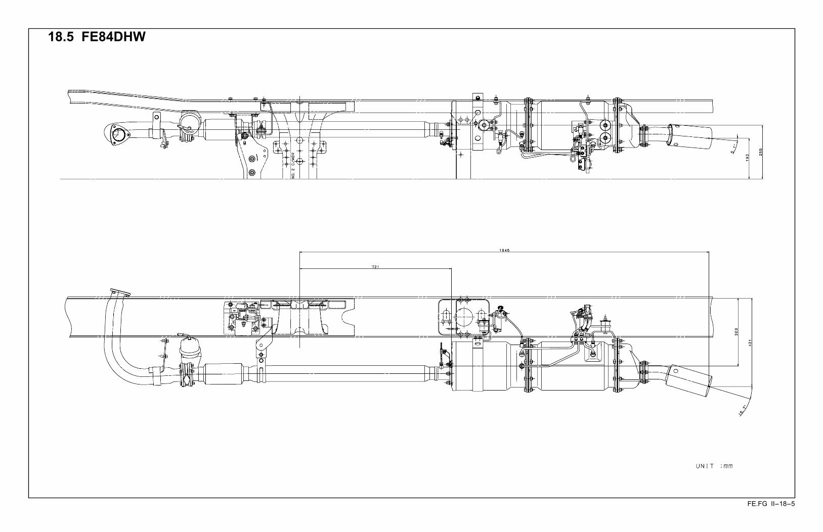
FE.FG II-18-5
18.5 FE84DHW
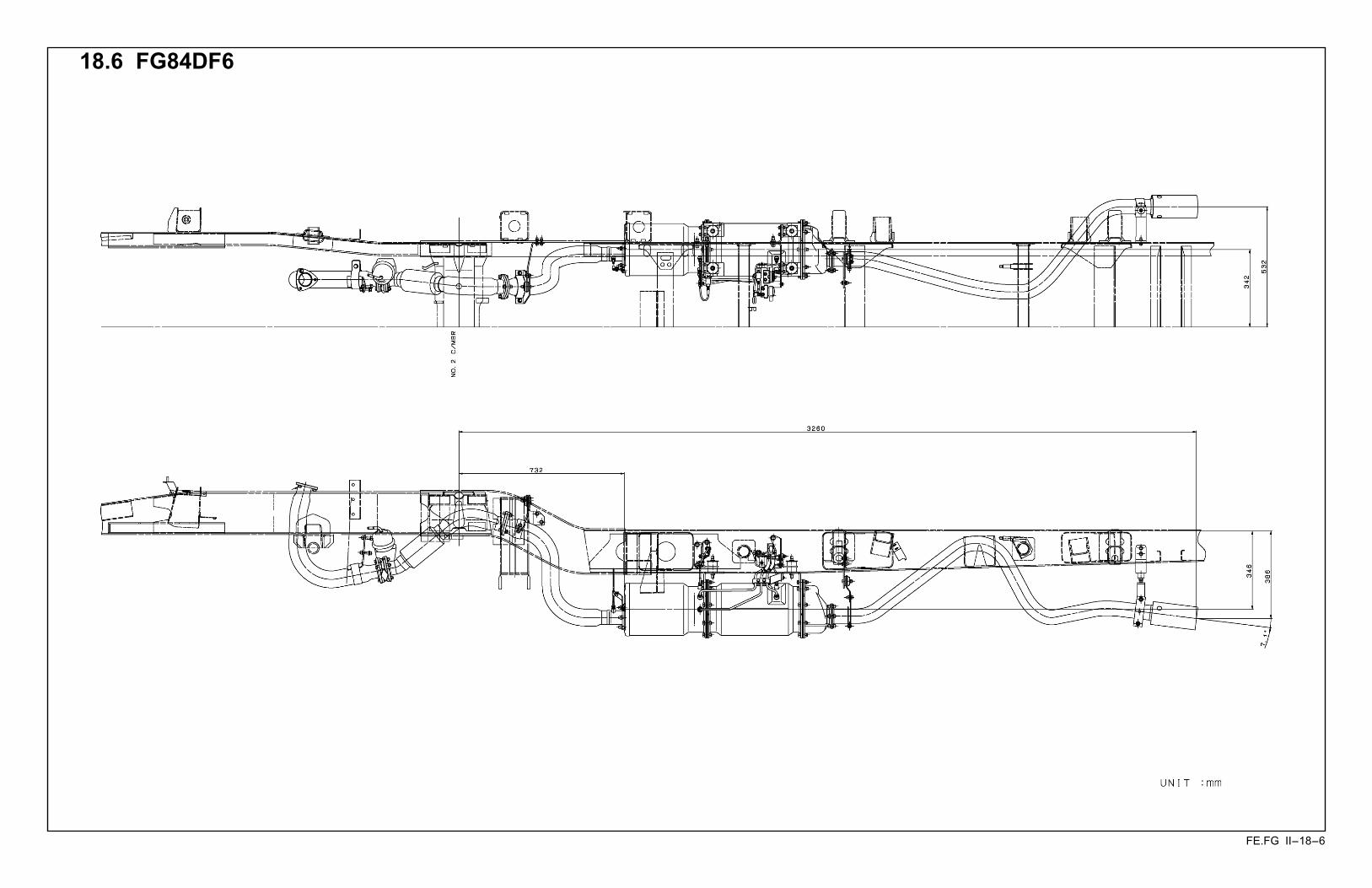
FE.FG II-18-6
18.6 FG84DF6
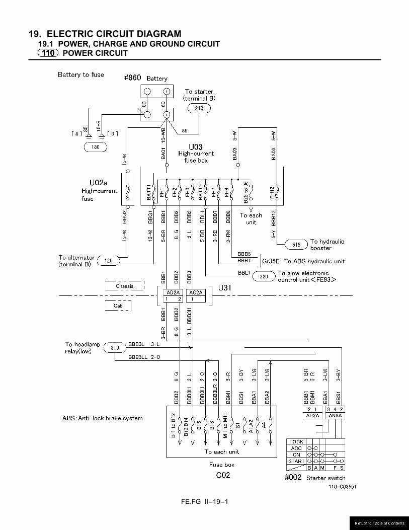
FE.FG II-19-1
19. ELECTRIC CIRCUIT DIAGRAM 19.1 POWER, CHARGE AND GROUND CIRCUIT
POWER CIRCUIT

FE.FG II-19-2
POWER CIRCUIT
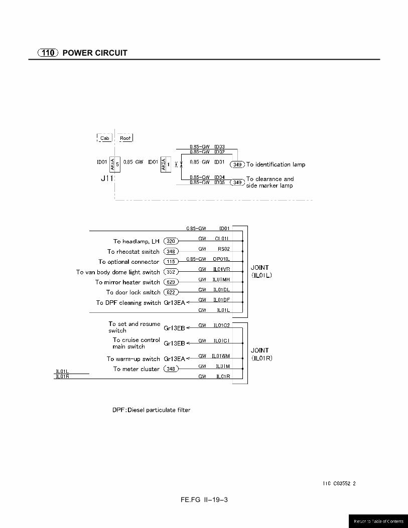
FE.FG II-19-3
POWER CIRCUIT
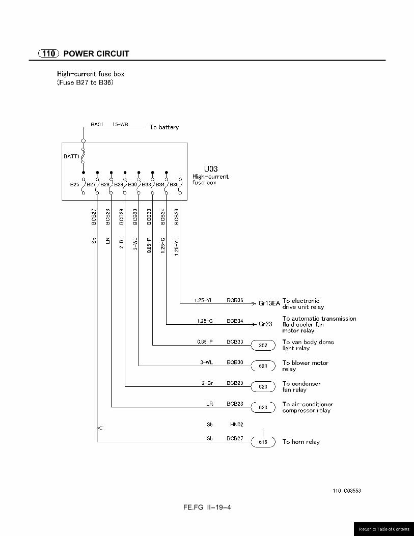
FE.FG II-19-4
POWER CIRCUIT
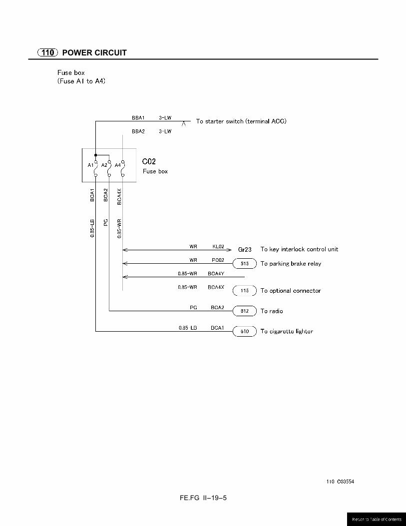
FE.FG II-19-5
POWER CIRCUIT
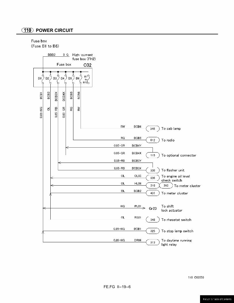
FE.FG II-19-6
POWER CIRCUIT
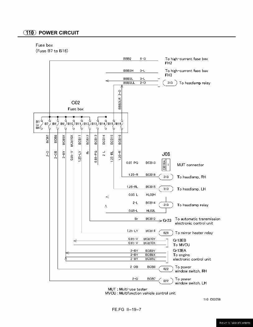
FE.FG II-19-7
POWER CIRCUIT
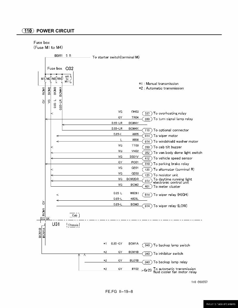
FE.FG II-19-8
POWER CIRCUIT
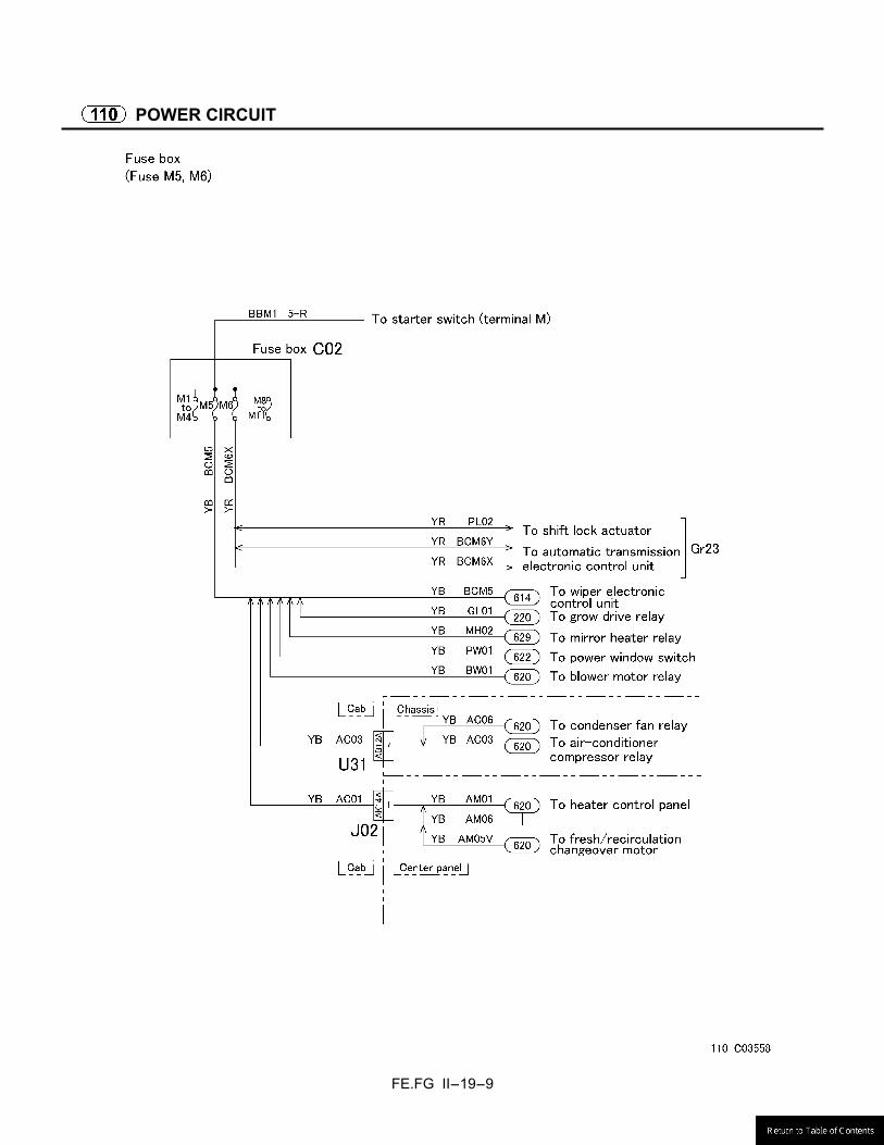
FE.FG II-19-9
POWER CIRCUIT

FE.FG II-19-10
POWER CIRCUIT
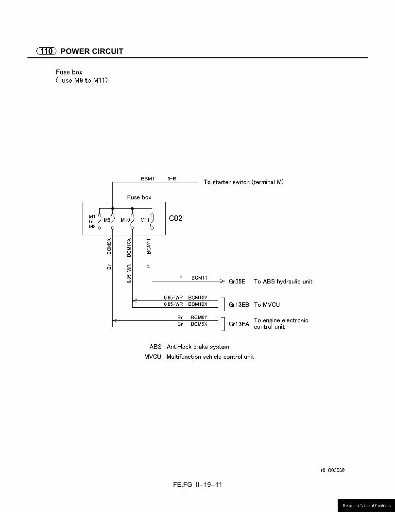
FE.FG II-19-11
POWER CIRCUIT
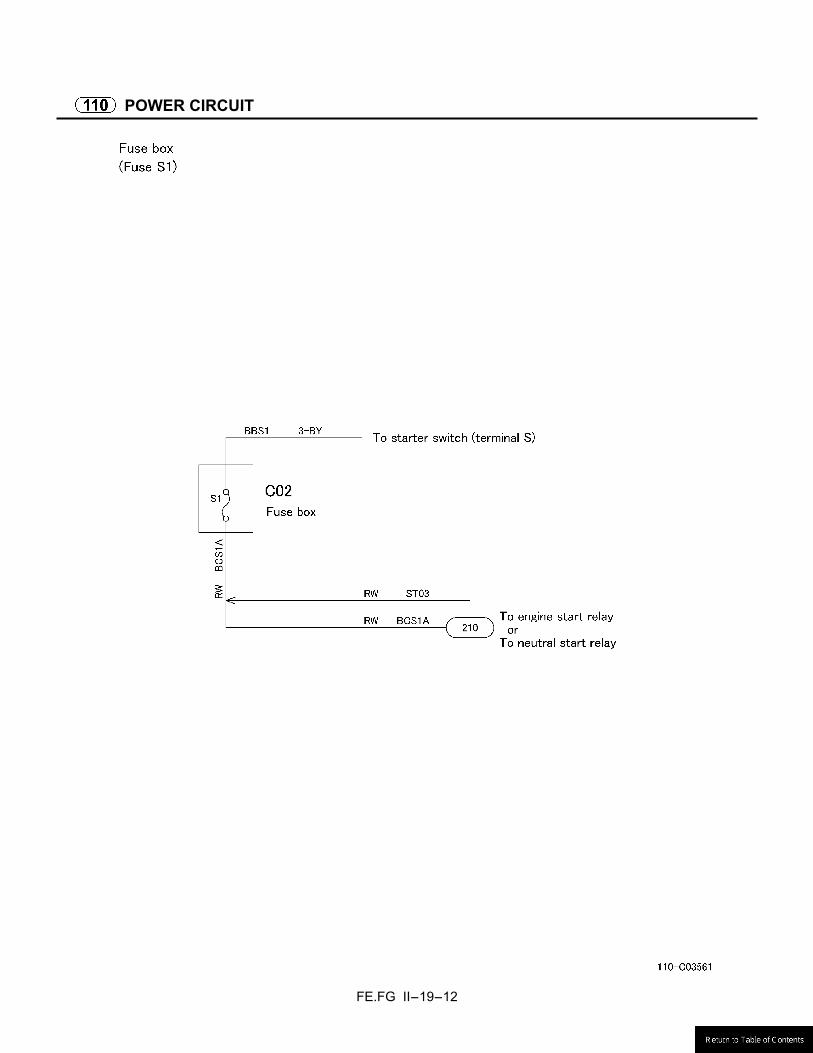
FE.FG II-19-12
POWER CIRCUIT

FE.FG II-19-13
RESERVE POWER CIRCUIT
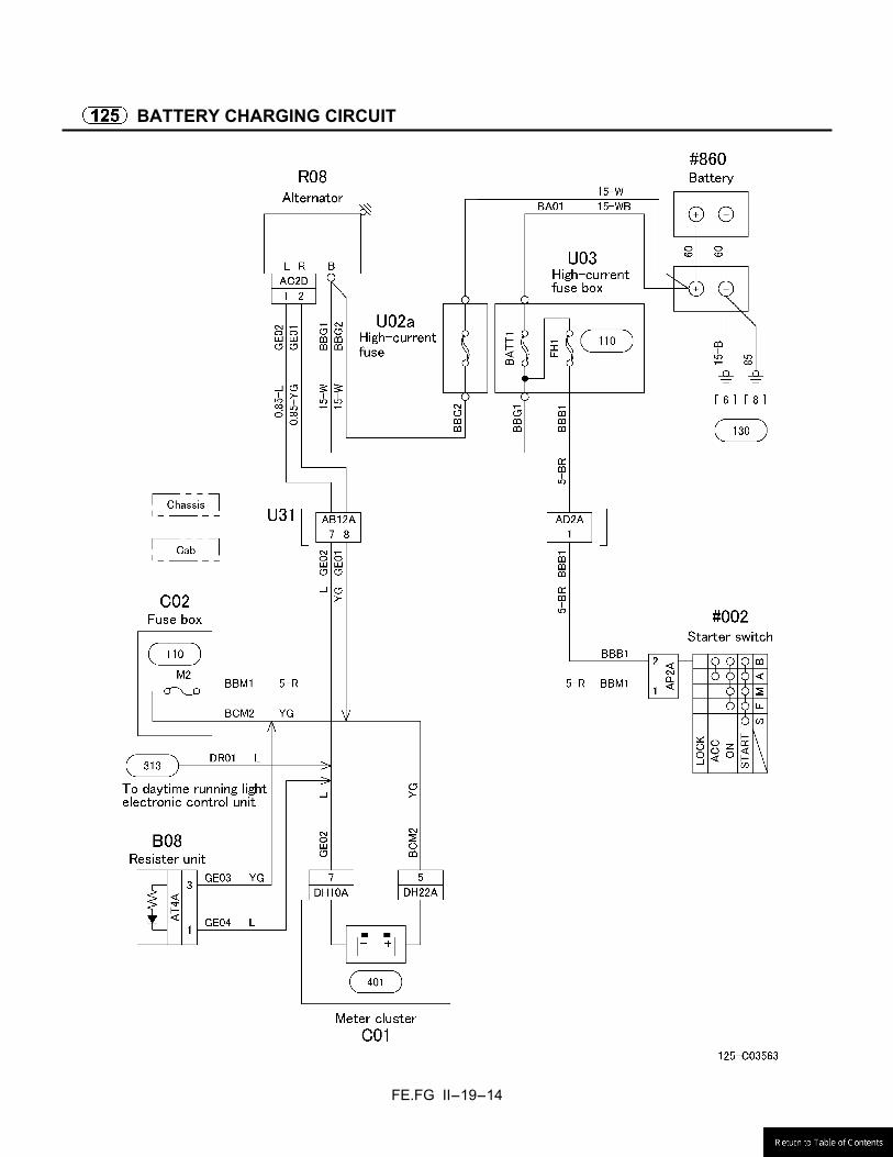
FE.FG II-19-14
BATTERY CHARGING CIRCUIT

FE.FG II-19-15
GROUND
FE.FG II-19-16
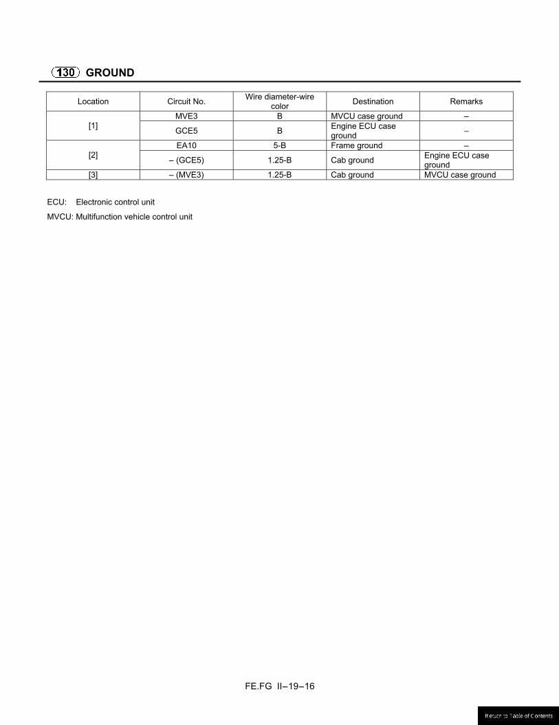
GROUND
Location Circuit No. Wire diameter-wire color Destination Remarks
MVE3 B MVCU case ground – [1] GCE5 B Engine ECU case
ground –
EA10 5-B Frame ground – [2] – (GCE5) 1.25-B Cab ground Engine ECU case
ground [3] – (MVE3) 1.25-B Cab ground MVCU case ground
ECU: Electronic control unit
MVCU: Multifunction vehicle control unit

FE.FG II-19-17
GROUND
FE.FG II-19-18
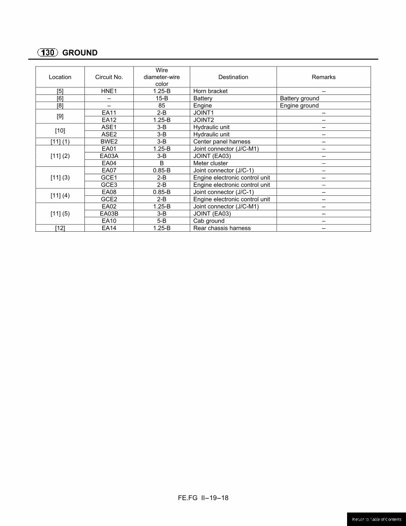
GROUND
Location Circuit No. Wire
diameter-wire color
Destination Remarks
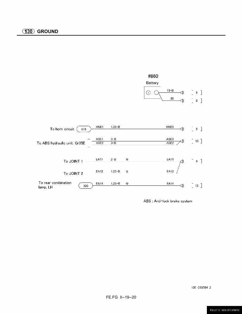
[5] HNE1 1.25-B Horn bracket – [6] – 15-B Battery Battery ground [8] – 85 Engine Engine ground
EA11 2-B JOINT1 – [9] EA12 1.25-B JOINT2 – ASE1 3-B Hydraulic unit – [10] ASE2 3-B Hydraulic unit –
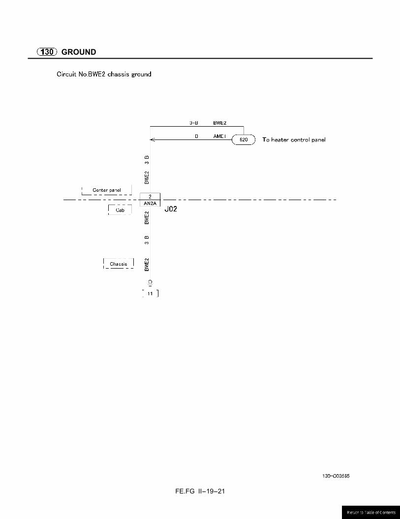
[11] (1) BWE2 3-B Center panel harness – EA01 1.25-B Joint connector (J/C-M1) –
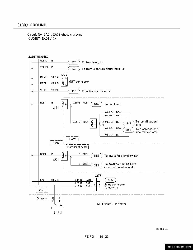
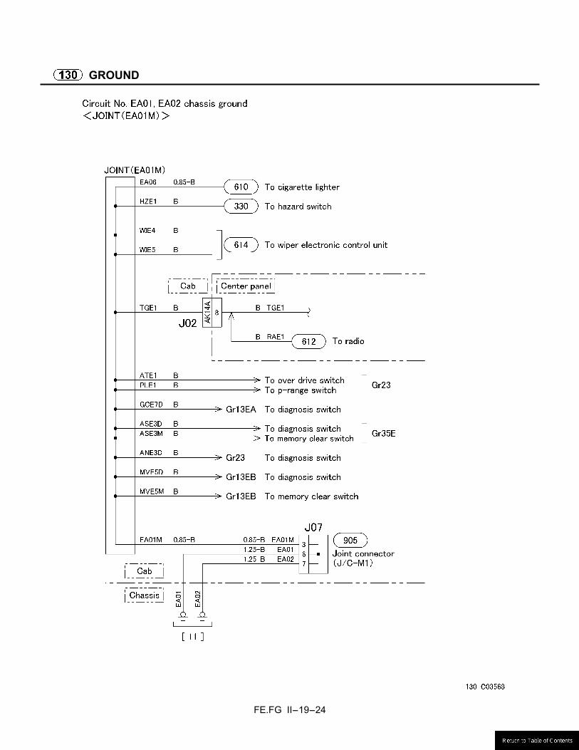
EA03A 3-B JOINT (EA03) – [11] (2) EA04 B Meter cluster – EA07 0.85-B Joint connector (J/C-1) – GCE1 2-B Engine electronic control unit – [11] (3) GCE3 2-B Engine electronic control unit – EA08 0.85-B Joint connector (J/C-1) – [11] (4) GCE2 2-B Engine electronic control unit – EA02 1.25-B Joint connector (J/C-M1) –
EA03B 3-B JOINT (EA03) – [11] (5) EA10 5-B Cab ground –
[12] EA14 1.25-B Rear chassis harness –
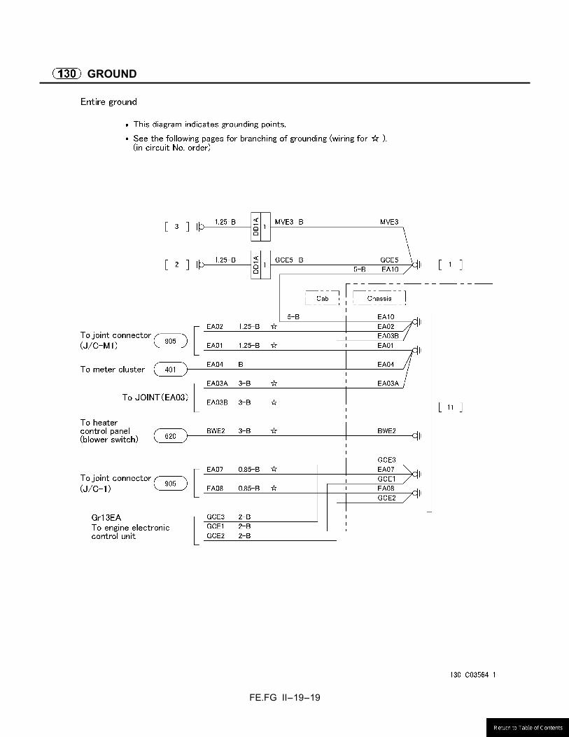
FE.FG II-19-19
GROUND
FE.FG II-19-20
GROUND
FE.FG II-19-21
GROUND

FE.FG II-19-22
GROUND
FE.FG II-19-23
GROUND
FE.FG II-19-24
GROUND

FE.FG II-19-25
GROUND
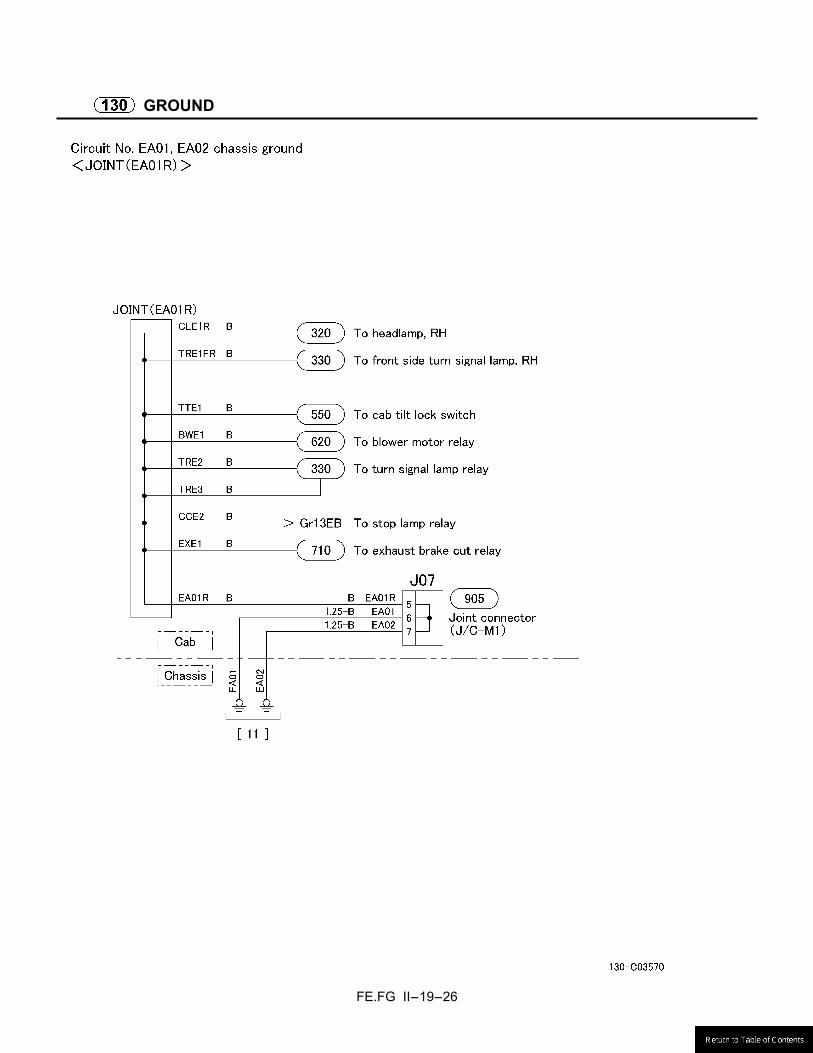
FE.FG II-19-26
GROUND
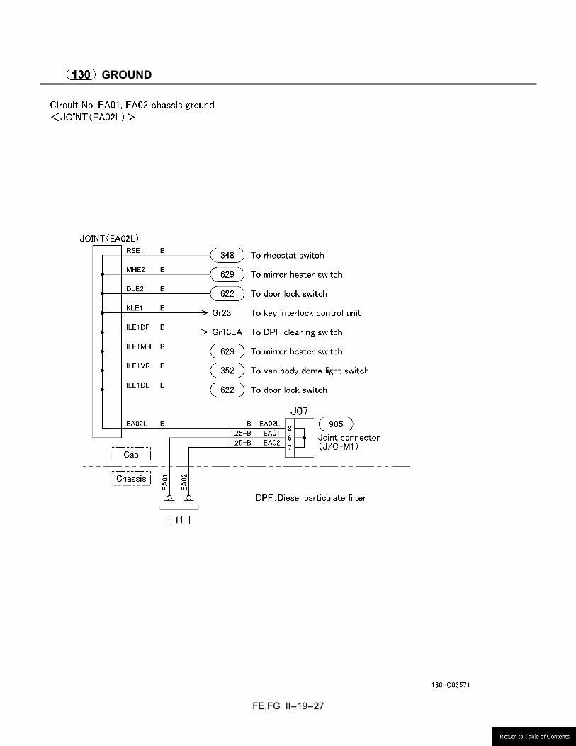
FE.FG II-19-27
GROUND

FE.FG II-19-28
GROUND
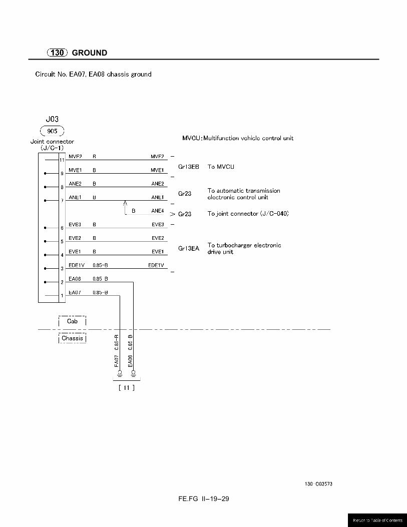
FE.FG II-19-29
GROUND
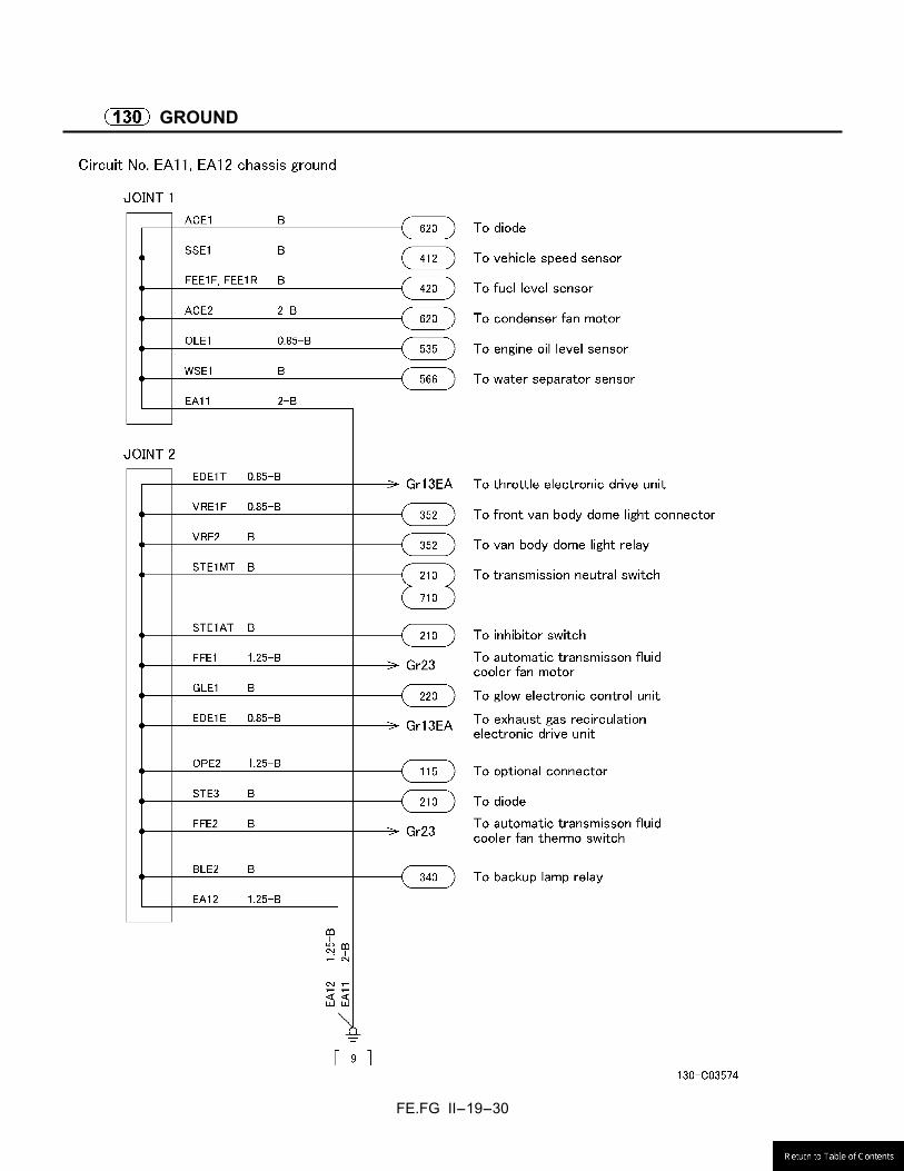
FE.FG II-19-30
GROUND

FE.FG II-19-31
GROUND
FE.FG II-19-32
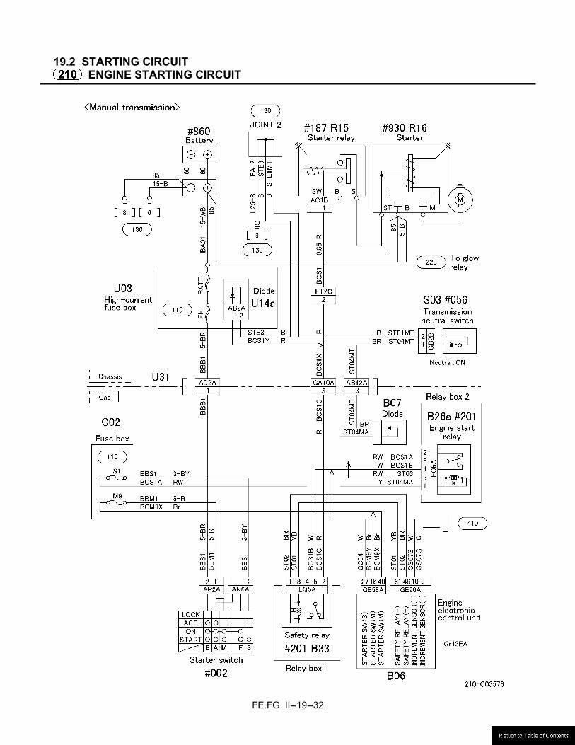
19.2 STARTING CIRCUIT
ENGINE STARTING CIRCUIT

FE.FG II-19-33
ENGINE STARTING CIRCUIT
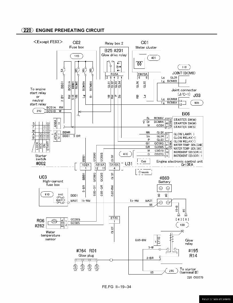
FE.FG II-19-34
ENGINE PREHEATING CIRCUIT

FE.FG II-19-35
ENGINE PREHEATING CIRCUIT
FE.FG II-19-36
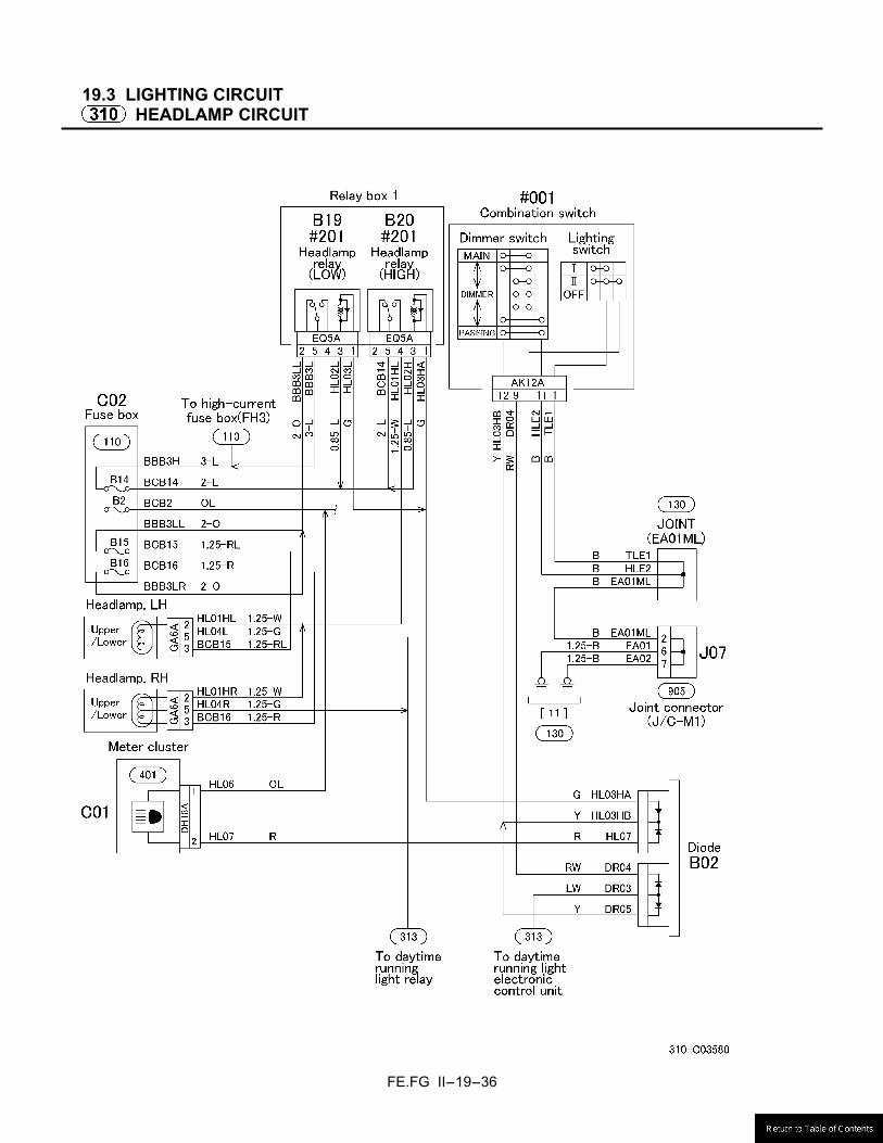
19.3 LIGHTING CIRCUIT
HEADLAMP CIRCUIT

FE.FG II-19-37
DAYTIME RUNNING LIGHT CIRCUIT
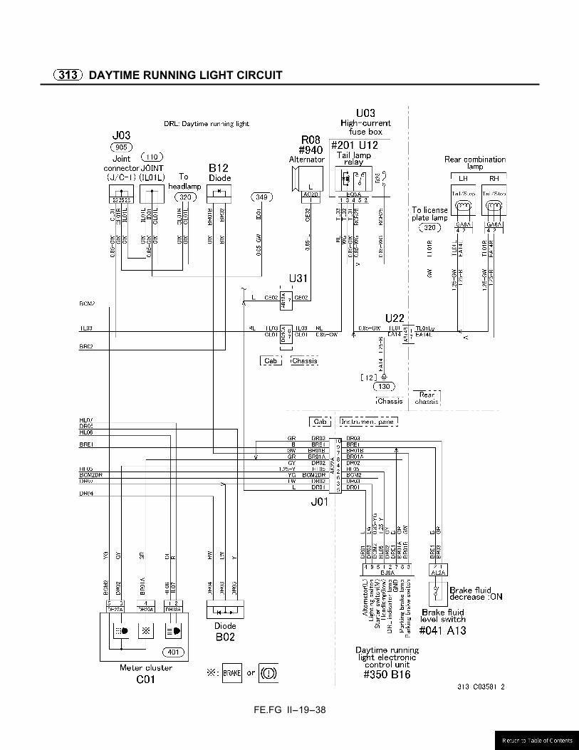
FE.FG II-19-38
DAYTIME RUNNING LIGHT CIRCUIT
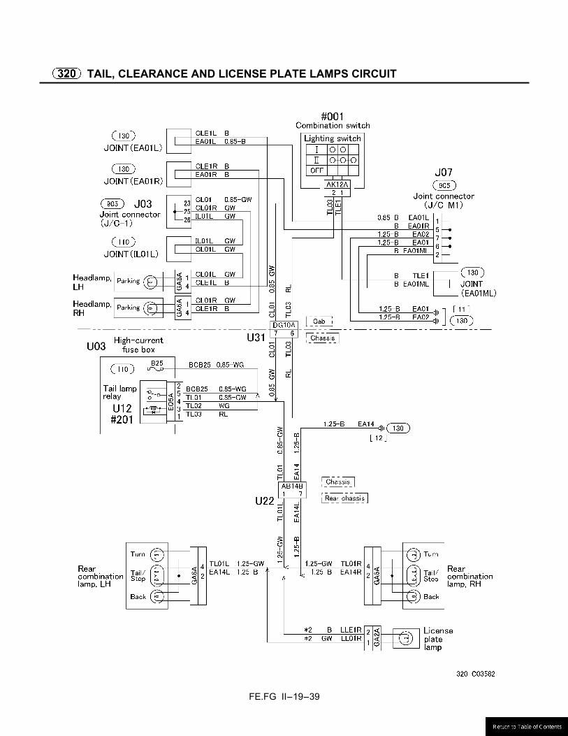
FE.FG II-19-39
TAIL, CLEARANCE AND LICENSE PLATE LAMPS CIRCUIT

FE.FG II-19-40
STOP LAMP CIRCUIT
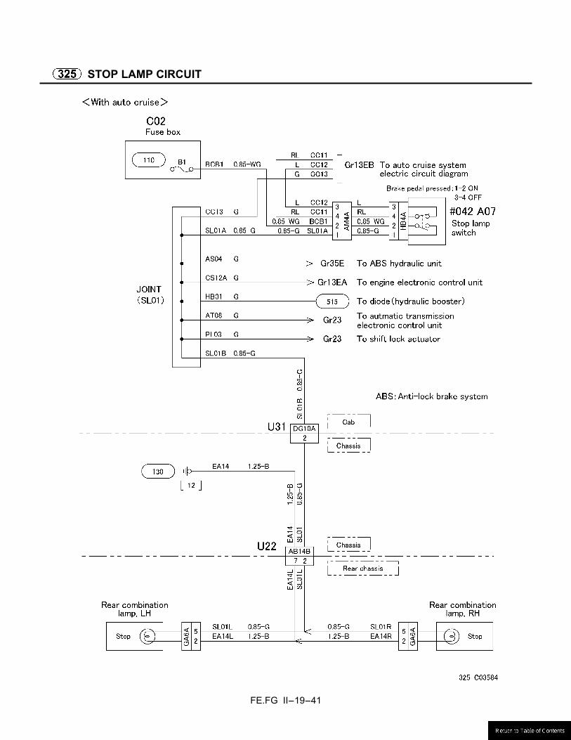
FE.FG II-19-41
STOP LAMP CIRCUIT
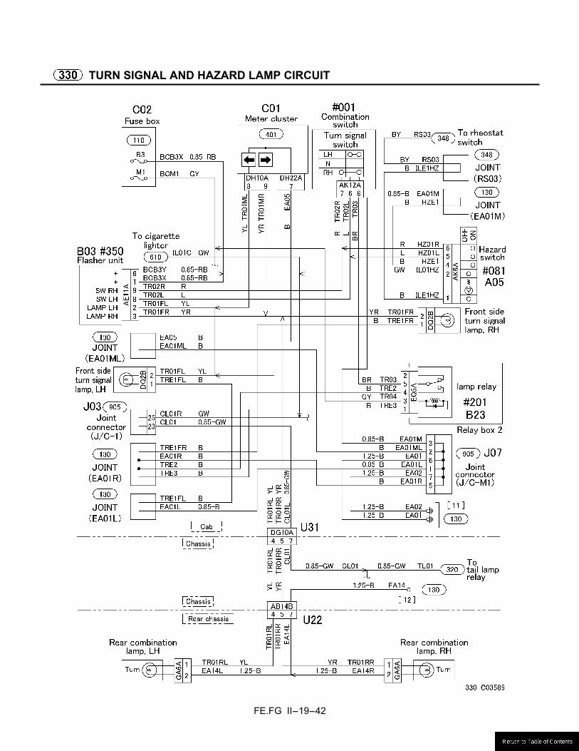
FE.FG II-19-42
TURN SIGNAL AND HAZARD LAMP CIRCUIT
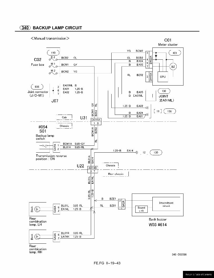
FE.FG II-19-43
BACKUP LAMP CIRCUIT
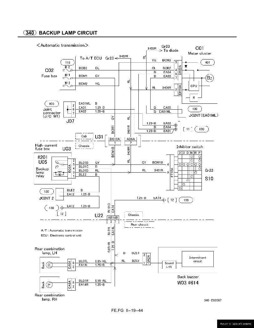
FE.FG II-19-44
BACKUP LAMP CIRCUIT
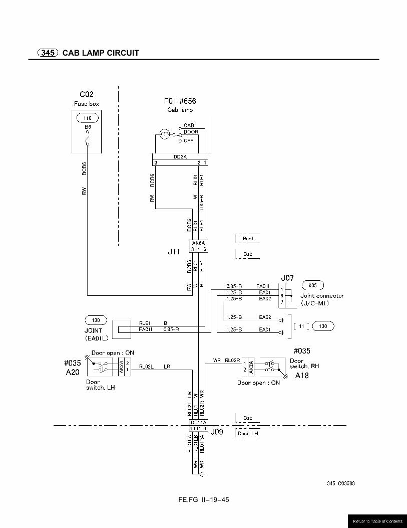
FE.FG II-19-45
CAB LAMP CIRCUIT
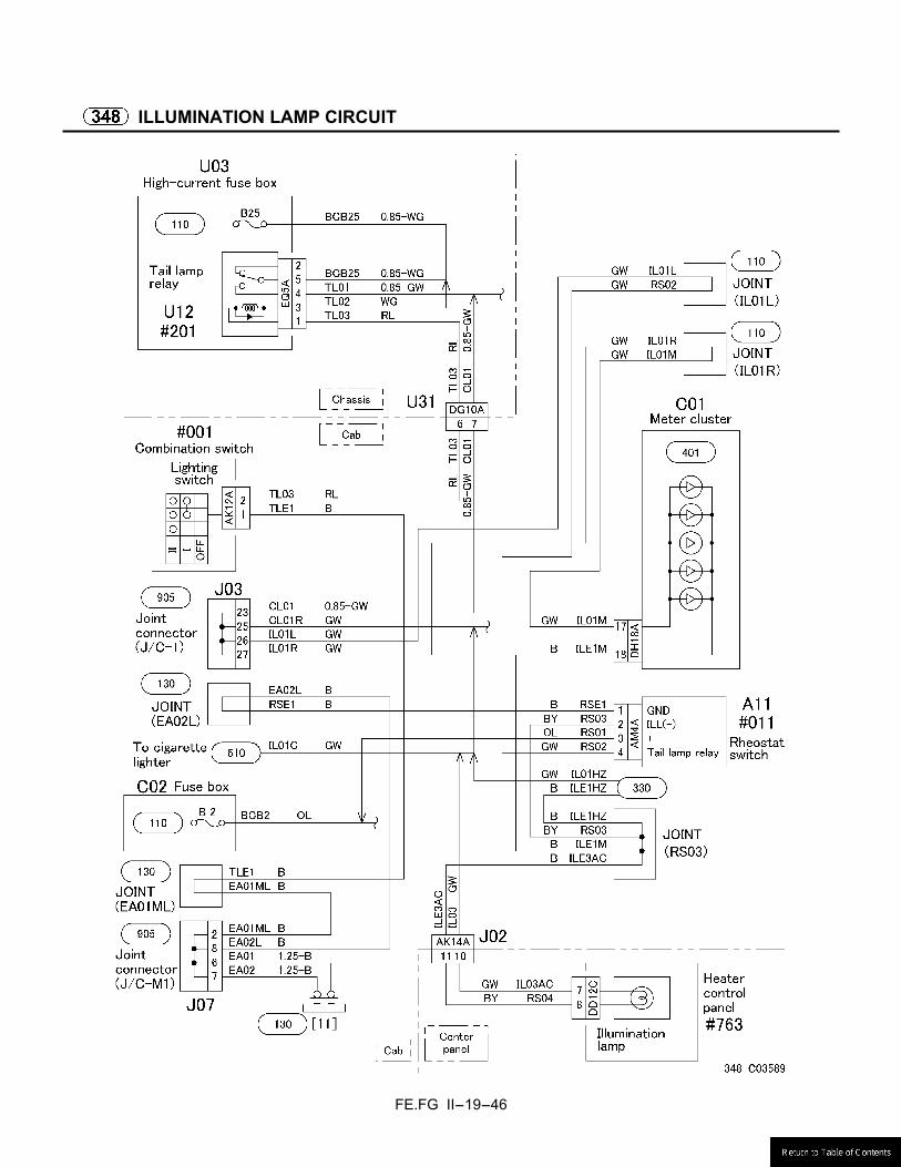
FE.FG II-19-46
ILLUMINATION LAMP CIRCUIT
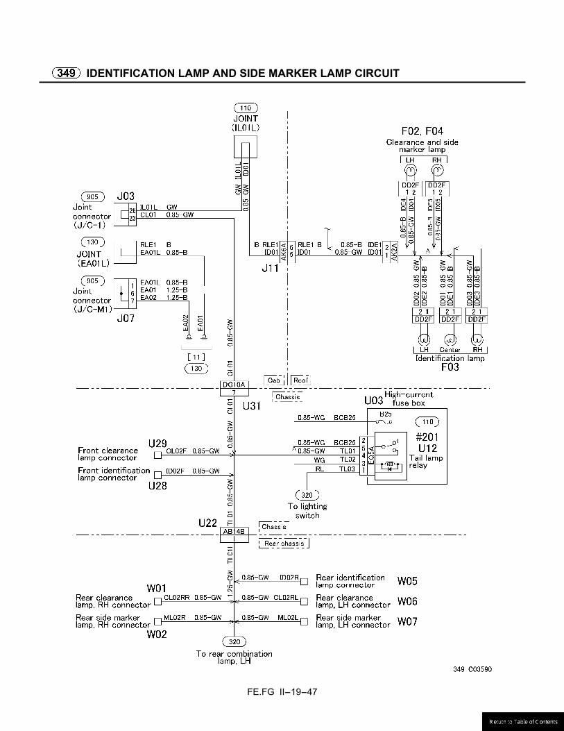
FE.FG II-19-47
IDENTIFICATION LAMP AND SIDE MARKER LAMP CIRCUIT

FE.FG II-19-48
VAN BODY DOME LIGHT CIRCUIT

FE.FG II-19-49
19.4 METER CLUSTER
METER CLUSTER INTERNAL CIRCUIT
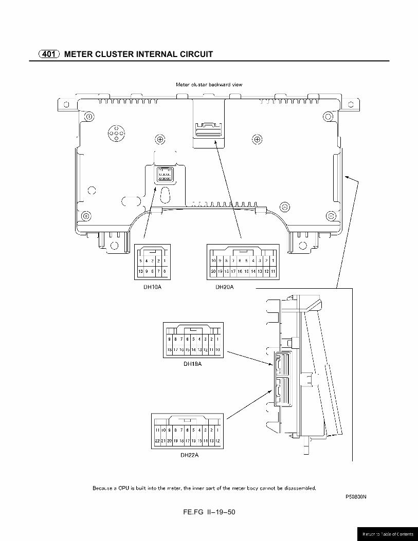
FE.FG II-19-50
METER CLUSTER INTERNAL CIRCUIT
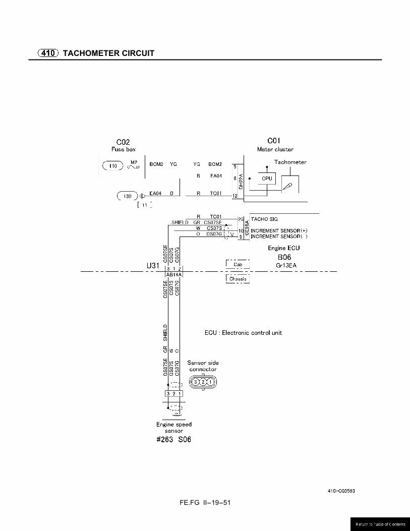
FE.FG II-19-51
TACHOMETER CIRCUIT

FE.FG II-19-52
SPEEDOMETER CIRCUIT

FE.FG II-19-53
FUEL GAUGE CIRCUIT
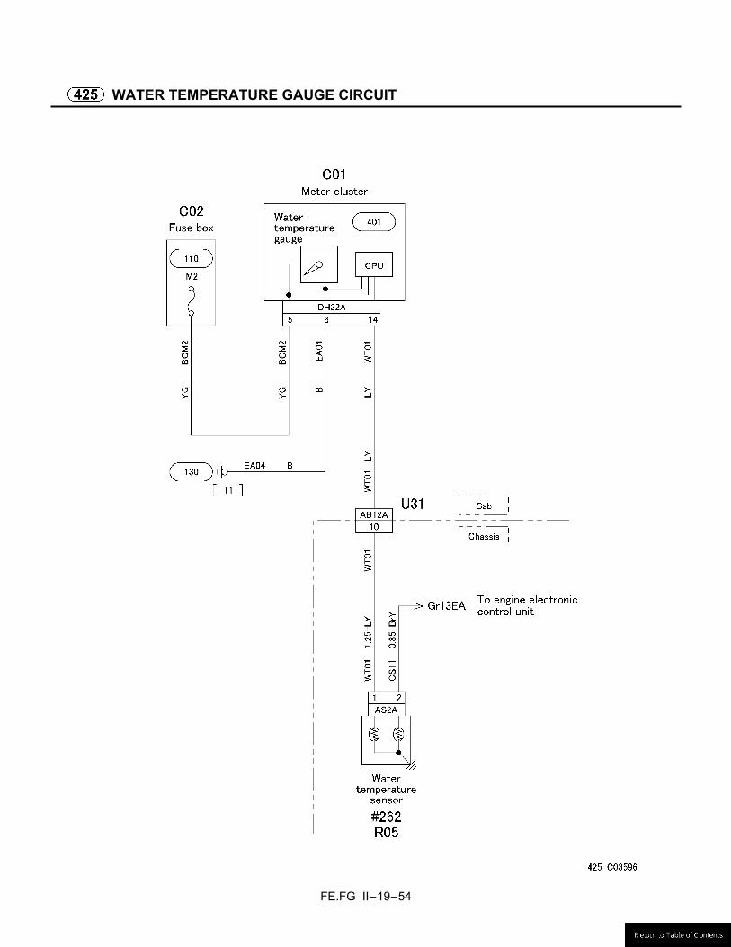
FE.FG II-19-54
WATER TEMPERATURE GAUGE CIRCUIT

FE.FG II-19-55
19.5 INDICATOR AND WARNING LAMP CIRCUIT
PARKING BRAKE INDICATOR CIRCUIT
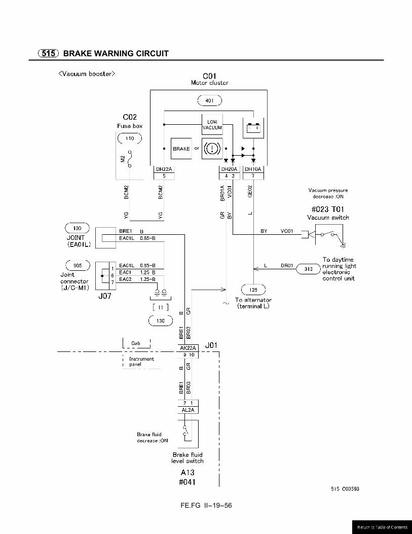
FE.FG II-19-56
BRAKE WARNING CIRCUIT

FE.FG II-19-57
BRAKE WARNING CIRCUIT
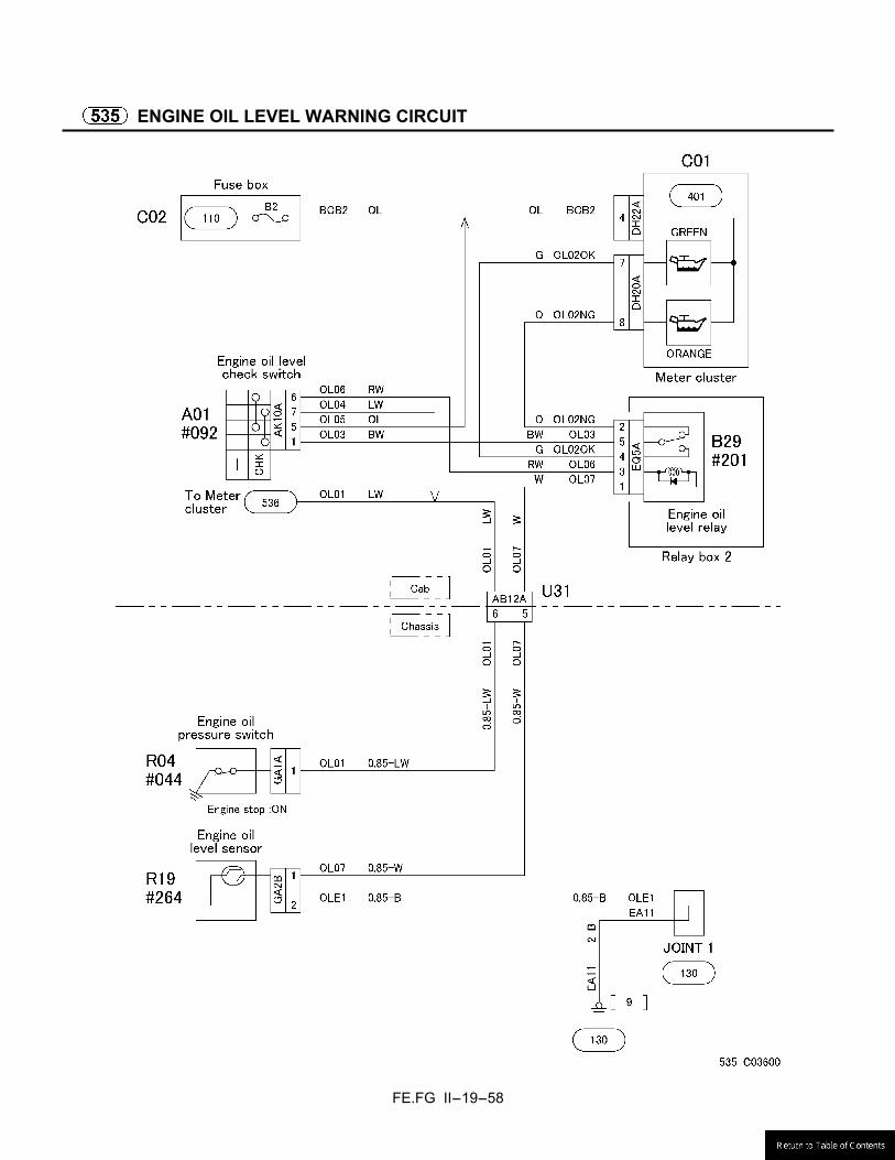
FE.FG II-19-58
ENGINE OIL LEVEL WARNING CIRCUIT
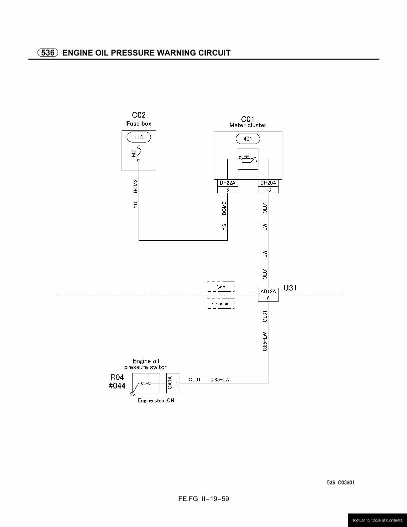
FE.FG II-19-59
ENGINE OIL PRESSURE WARNING CIRCUIT
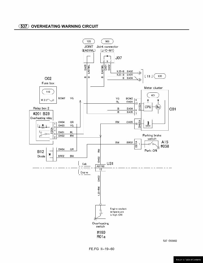
FE.FG II-19-60
OVERHEATING WARNING CIRCUIT
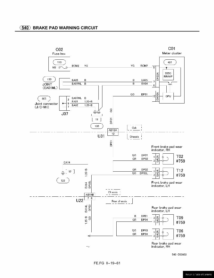
FE.FG II-19-61
BRAKE PAD WARNING CIRCUIT
FE.FG II-19-62
CAB TILT WARNING CIRCUIT

FE.FG II-19-63
FUEL FILTER WARNING CIRCUIT
FE.FG II-19-64
19.6 CAB SIDE ELECTRICAL CIRCUIT
CIGARETTE LIGHTER CIRCUIT
FE.FG II-19-65
AUDIO CIRCUIT
FE.FG II-19-66
WIPER AND WASHER CIRCUIT
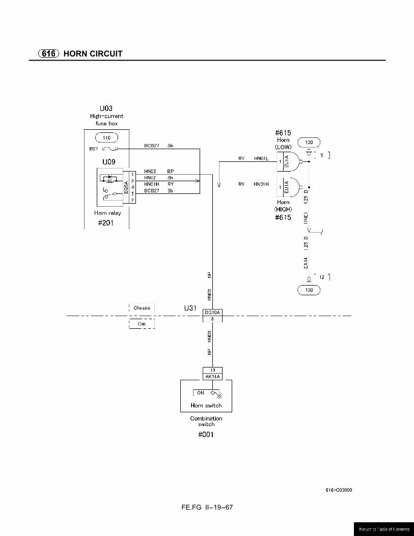
FE.FG II-19-67
HORN CIRCUIT

FE.FG II-19-68
AIR-CONDITIONER CIRCUIT
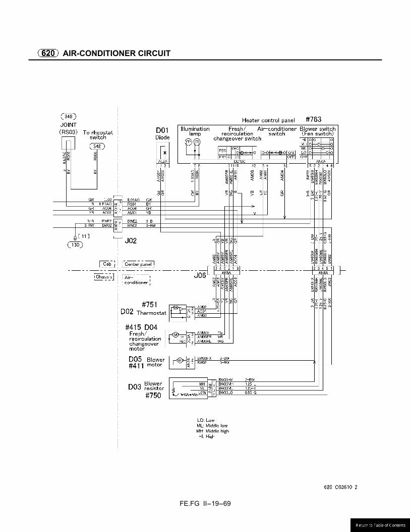
FE.FG II-19-69
AIR-CONDITIONER CIRCUIT

FE.FG II-19-70
POWER WINDOW AND CENTRAL DOOR LOCK CIRCUIT
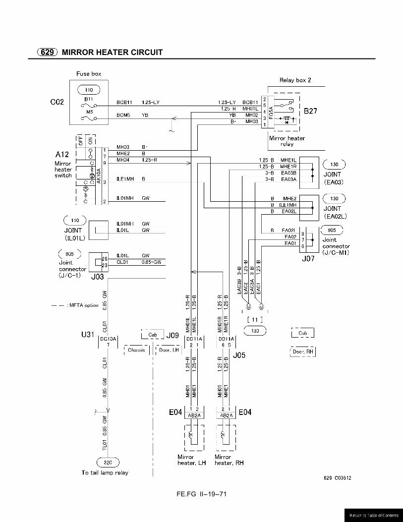
FE.FG II-19-71
MIRROR HEATER CIRCUIT
FE.FG II-19-72
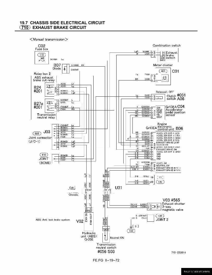
19.7 CHASSIS SIDE ELECTRICAL CIRCUIT
EXHAUST BRAKE CIRCUIT

FE.FG II-19-73
EXHAUST BRAKE CIRCUIT
FE.FG II-19-74
19.8 ENGINE AND TRANSMISSION SIDE ELECTRICAL CIRCUIT
TRANSMISSION POWER TAKE-OFF CIRCUIT

FE.FG II-19-75
19.9 OTHER CIRCUIT
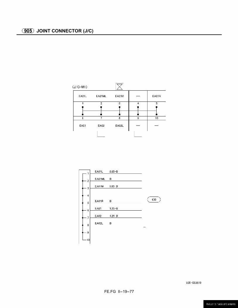
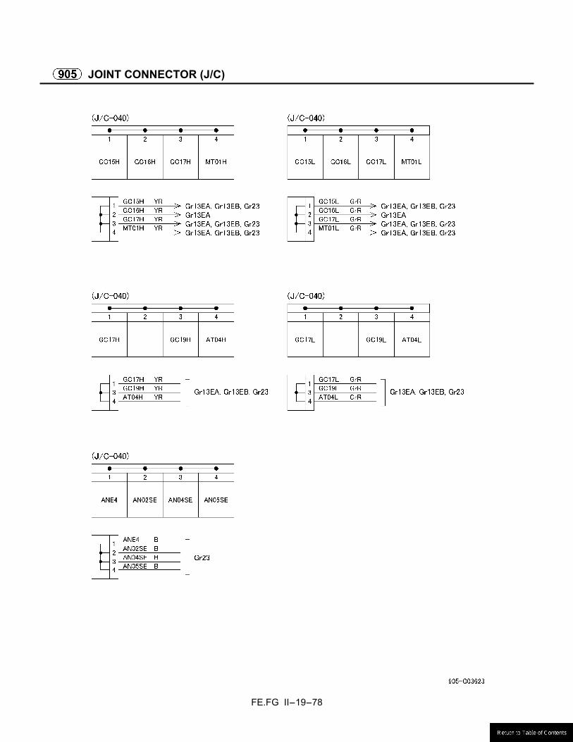
JOINT CONNECTOR (J/C)

FE.FG II-19-76
JOINT CONNECTOR (J/C)
FE.FG II-19-77
JOINT CONNECTOR (J/C)
FE.FG II-19-78
JOINT CONNECTOR (J/C)

FE.FG II-19-79
DIAGNOSIS SWITCH AND MEMORY CLEAR SWITCH

FE.FG II-19-80
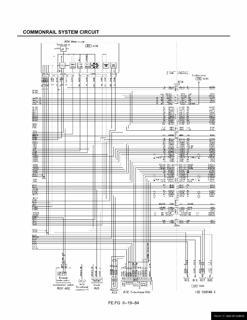
COMMONRAIL SYSTEM CIRCUIT

FE.FG II-19-81
COMMONRAIL SYSTEM CIRCUIT

FE.FG II-19-82
COMMONRAIL SYSTEM CIRCUIT

FE.FG II-19-83
COMMONRAIL SYSTEM CIRCUIT
FE.FG II-19-84
COMMONRAIL SYSTEM CIRCUIT
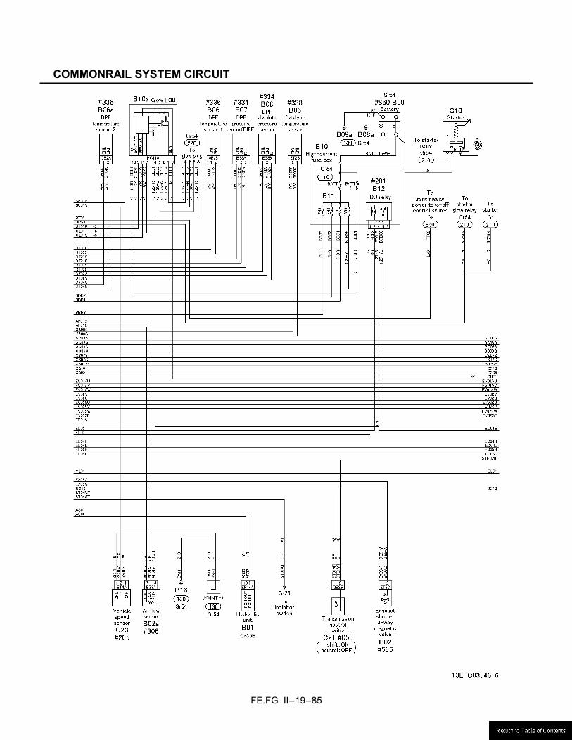
FE.FG II-19-85
COMMONRAIL SYSTEM CIRCUIT
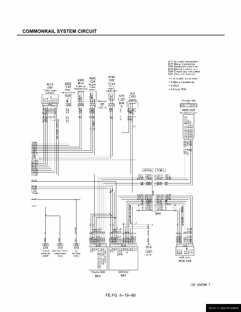
FE.FG II-19-86
COMMONRAIL SYSTEM CIRCUIT

FE.FG II-19-87
AUTOCRUISE SYSTEM CIRCUIT

FE.FG II-19-88
AUTOCRUISE SYSTEM CIRCUIT
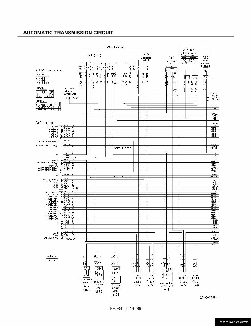
FE.FG II-19-89
AUTOMATIC TRANSMISSION CIRCUIT
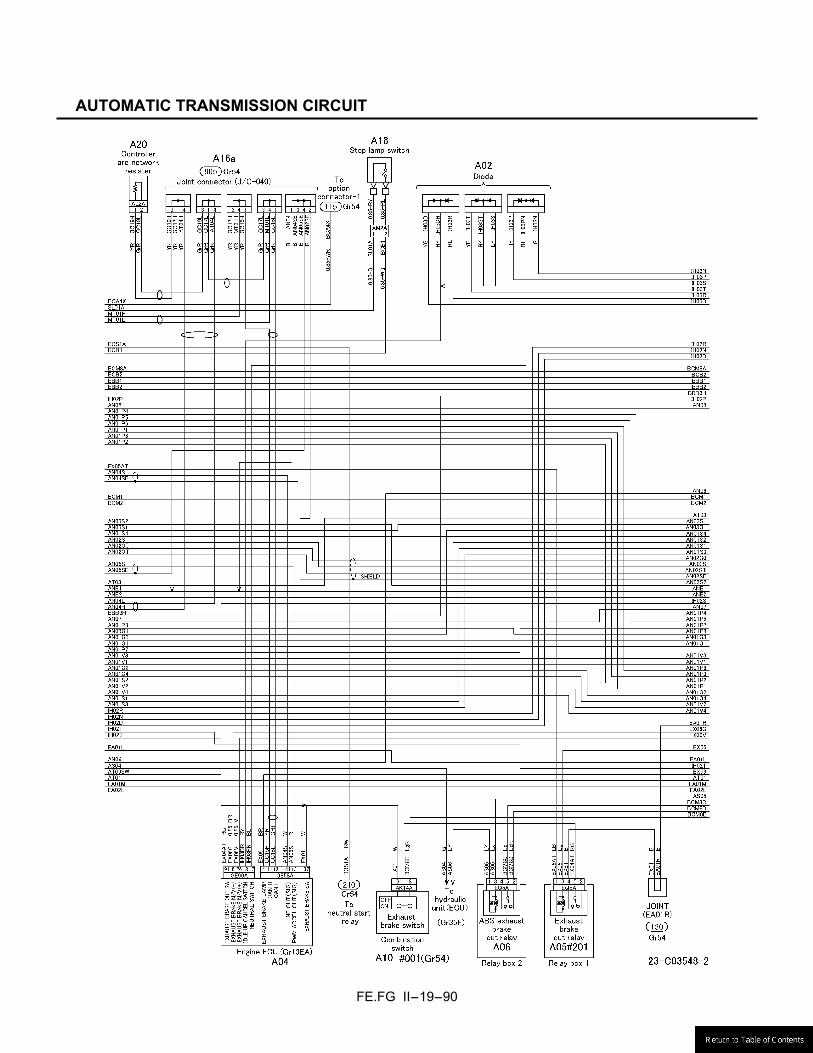
FE.FG II-19-90
AUTOMATIC TRANSMISSION CIRCUIT
FE.FG II-19-91
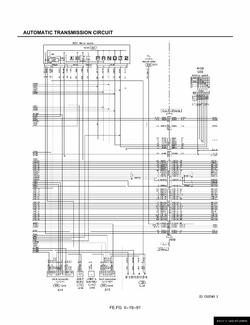
AUTOMATIC TRANSMISSION CIRCUIT
FE.FG II-19-92
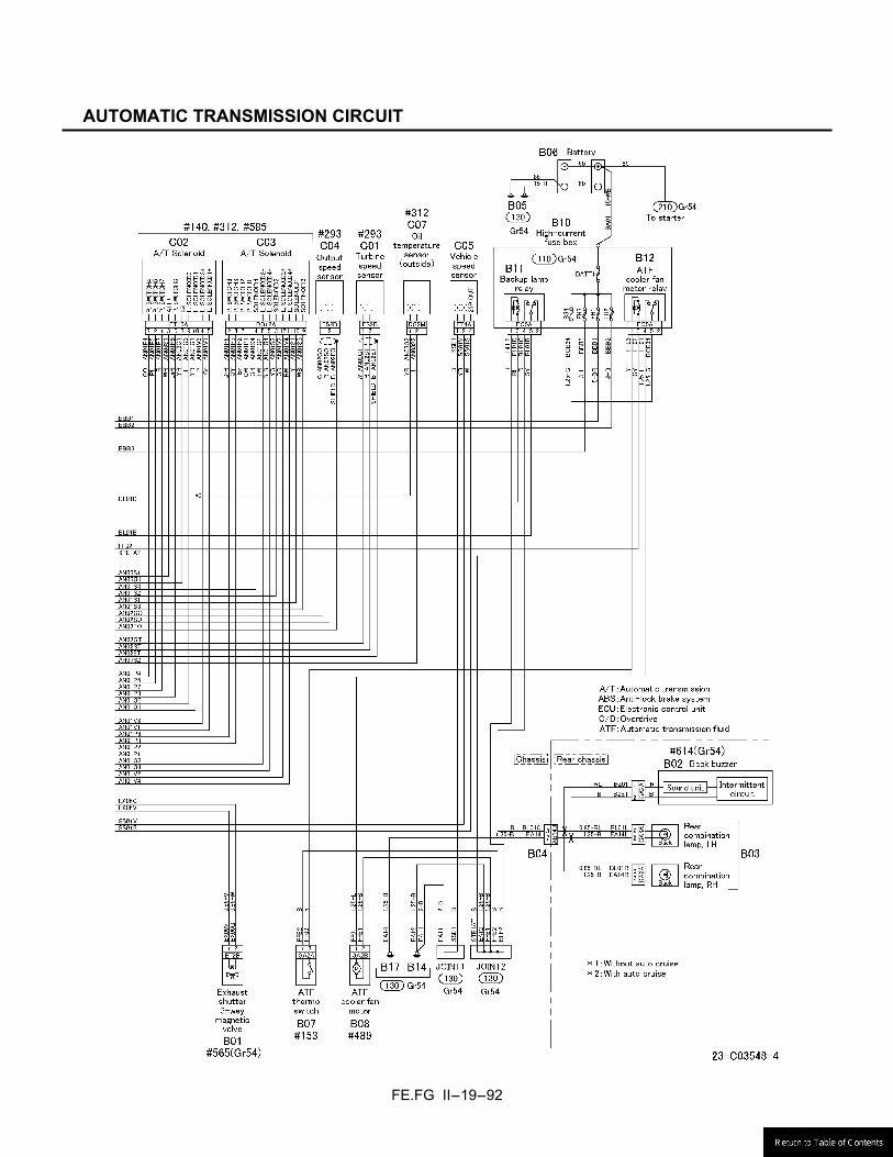
AUTOMATIC TRANSMISSION CIRCUIT
FE.FG II-19-93
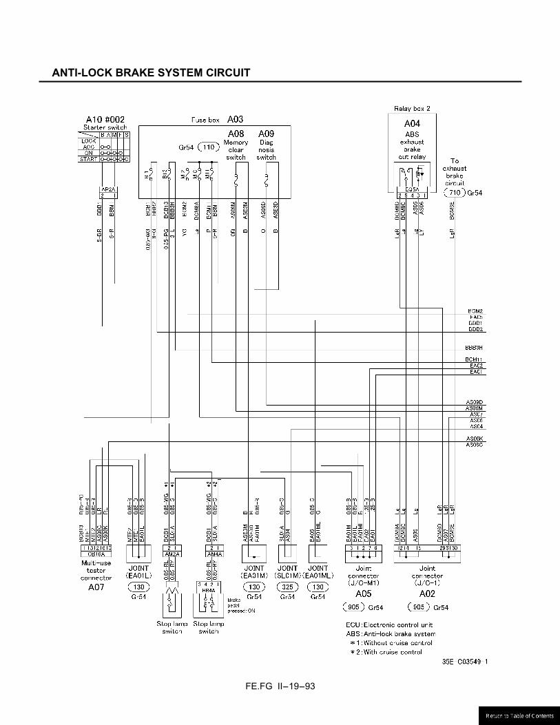
ANTI-LOCK BRAKE SYSTEM CIRCUIT
FE.FG II-19-94
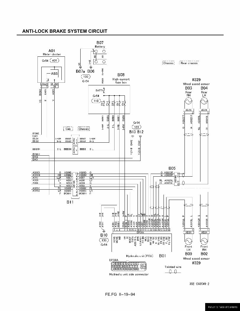
ANTI-LOCK BRAKE SYSTEM CIRCUIT

BODY BUILDER’S DRAWINGS AND
SUPPORTING DATA
SEP. 2007