body builder’s drawings and supporting data€¦ · body builder’s drawings and supporting data...
TRANSCRIPT
BODY BUILDER’S DRAWINGS AND
SUPPORTING DATA
LIT. No. LTE04001-A
JUNE 2004

INTRODUCTION
This book has been designed to provide information for body and equipment manufacturers who mount their products on MITSUBISHI-FUSO FE.FG chassis. We believe that all the detailed information which is essential for that purpose is contained in this book, but if you require any additional data or information, please contact:
MITSUBISHI FUSO TRUCK OF AMERICA, INC. 2015 Center Square Road, Logan Township, NJ 08085 (Phone : (856) 467-4500)
The specifications and descriptions contined in this book are based on the latest product information at the time of publication, but since the design of MITSUBISHI-FUSO truck is continuously being improved, we must reserve the right to discontinue or change at any time without prior notice.
COMPLIANCE WITH FEDERAL MOTOR VEHICLE SAFETY STANDARDS
The federal government has established Federal Motor Vehicle Safety Standards (FMVSS) for various categories of motor vehicles and motor vehicle equipment under the provisions of the National Traffic and Motor Vehicle Safety Act of 1966. The Act imposes important legal responsibilities on manufacturers, dealers, body builders and others engaged in the marketing of motor vehicles and motor vehicle equipment. Vehicles manufactured by Mitsubishi FUSO Truck & Bus Corporation (MFTBC) for the subsequent installation of commercial bodies are classified as incomplete vehicles. These vehicles fully comply with certain applicable Motor Vehicle Safety Standards, and partially (or do not) comply with others. They cannot be certified fully because certain components which are required for certification are not furnished. Under present federal regulations, vehicles completed from these units are required to meet all applicable standards in effect on the date of manufacture of the incomplete vehicle, the date of final completion, or date between those two dates, as determined by their final configuration. MFTBC incomplete vehicles carry in the glove box a document, as shown on the next page, that provides the vehicle types (truck) into which they may appropriately be completed, and the degree to which the incomplete vehicles comply with each of the standards in effect on the date of its manufacture. The completing manufacturer must certify compliance with all applicable standards, but may rely on MFTBC certification for those standards so indicated in the instructions for completing the vehicle document, provided that the instructions for completing the vehicle are followed. Questions may be directed to the Engineering or Service Department of MFTBC. Alterations, modifications, or additions to the vehicle which affect compliance with FMVSS are not covered by MFTBC certification and are the responsibility of the completing manufacturer. Likewise the completing manufacturer must assume responsibility for compliance with changes in federal requirements that occur after the manufacture of the incomplete vehicle by MFTBC, if he elects to certify compliance as of a later date.
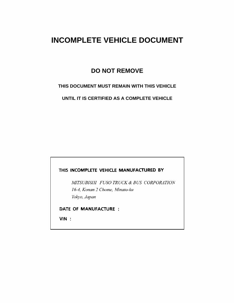
INCOMPLETE VEHICLE DOCUMENT
DO NOT REMOVE
THIS DOCUMENT MUST REMAIN WITH THIS VEHICLE
UNTIL IT IS CERTIFIED AS A COMPLETE VEHICLE
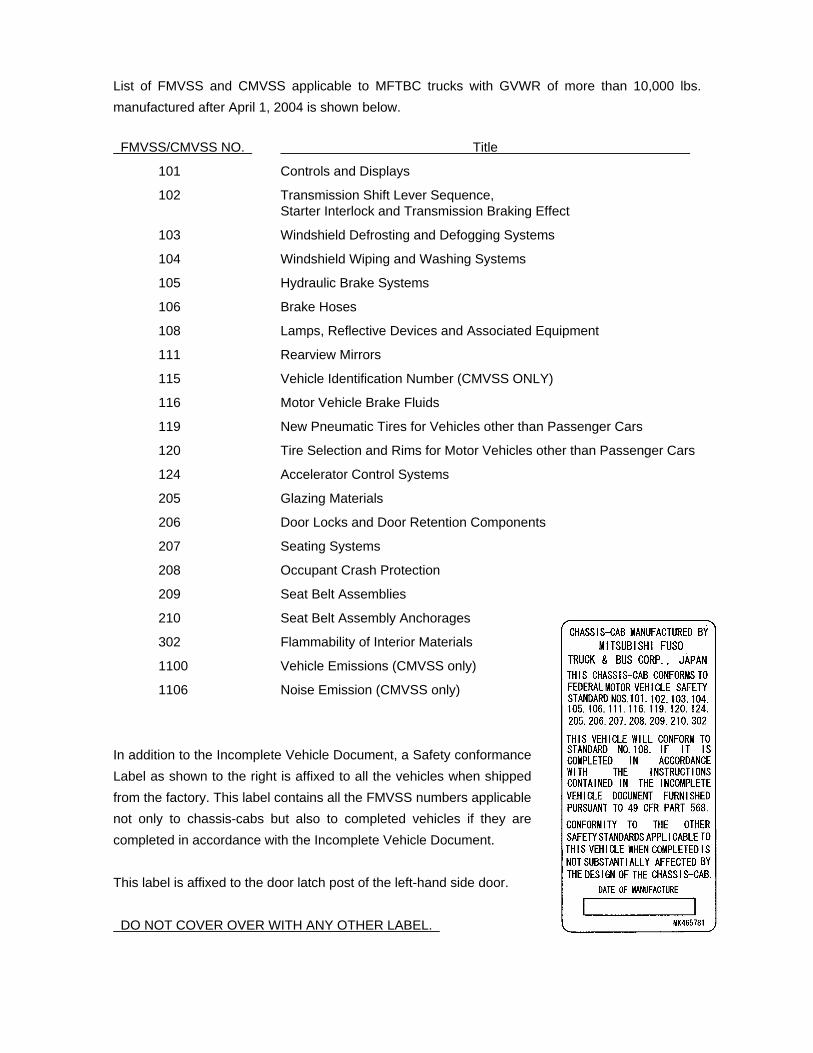
List of FMVSS and CMVSS applicable to MFTBC trucks with GVWR of more than 10,000 lbs. manufactured after April 1, 2004 is shown below. FMVSS/CMVSS NO. Title
101 Controls and Displays
102 Transmission Shift Lever Sequence, Starter Interlock and Transmission Braking Effect
103 Windshield Defrosting and Defogging Systems
104 Windshield Wiping and Washing Systems
105 Hydraulic Brake Systems
106 Brake Hoses
108 Lamps, Reflective Devices and Associated Equipment
111 Rearview Mirrors
115 Vehicle Identification Number (CMVSS ONLY)
116 Motor Vehicle Brake Fluids
119 New Pneumatic Tires for Vehicles other than Passenger Cars
120 Tire Selection and Rims for Motor Vehicles other than Passenger Cars
124 Accelerator Control Systems
205 Glazing Materials
206 Door Locks and Door Retention Components
207 Seating Systems
208 Occupant Crash Protection
209 Seat Belt Assemblies
210 Seat Belt Assembly Anchorages
302 Flammability of Interior Materials
1100 Vehicle Emissions (CMVSS only)
1106 Noise Emission (CMVSS only)
In addition to the Incomplete Vehicle Document, a Safety conformance Label as shown to the right is affixed to all the vehicles when shipped from the factory. This label contains all the FMVSS numbers applicable not only to chassis-cabs but also to completed vehicles if they are completed in accordance with the Incomplete Vehicle Document. This label is affixed to the door latch post of the left-hand side door. DO NOT COVER OVER WITH ANY OTHER LABEL.
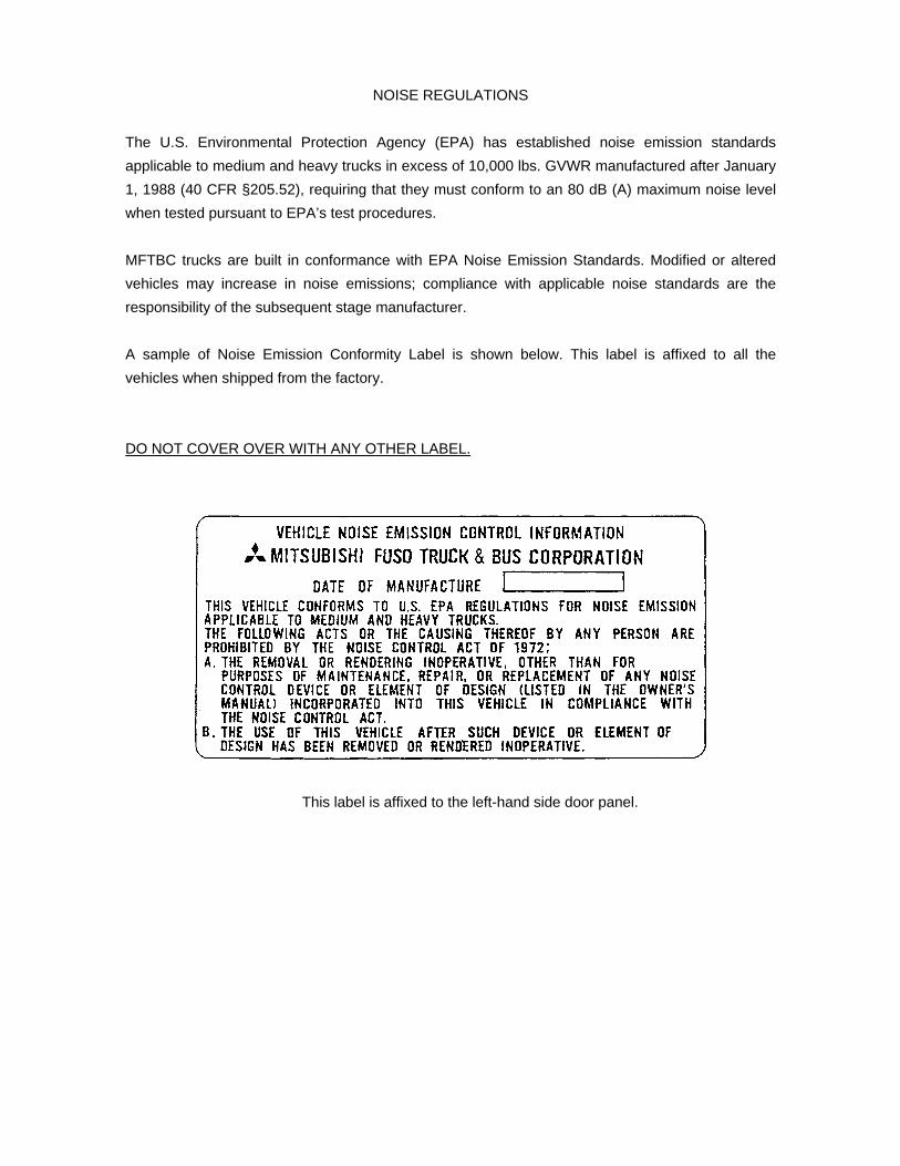
NOISE REGULATIONS
The U.S. Environmental Protection Agency (EPA) has established noise emission standards applicable to medium and heavy trucks in excess of 10,000 lbs. GVWR manufactured after January 1, 1988 (40 CFR §205.52), requiring that they must conform to an 80 dB (A) maximum noise level when tested pursuant to EPA’s test procedures. MFTBC trucks are built in conformance with EPA Noise Emission Standards. Modified or altered vehicles may increase in noise emissions; compliance with applicable noise standards are the responsibility of the subsequent stage manufacturer. A sample of Noise Emission Conformity Label is shown below. This label is affixed to all the vehicles when shipped from the factory. DO NOT COVER OVER WITH ANY OTHER LABEL.
This label is affixed to the left-hand side door panel.
PART I
GENERAL PRINCIPLES OF
BODY AND EQUIPMENT MOUNTING
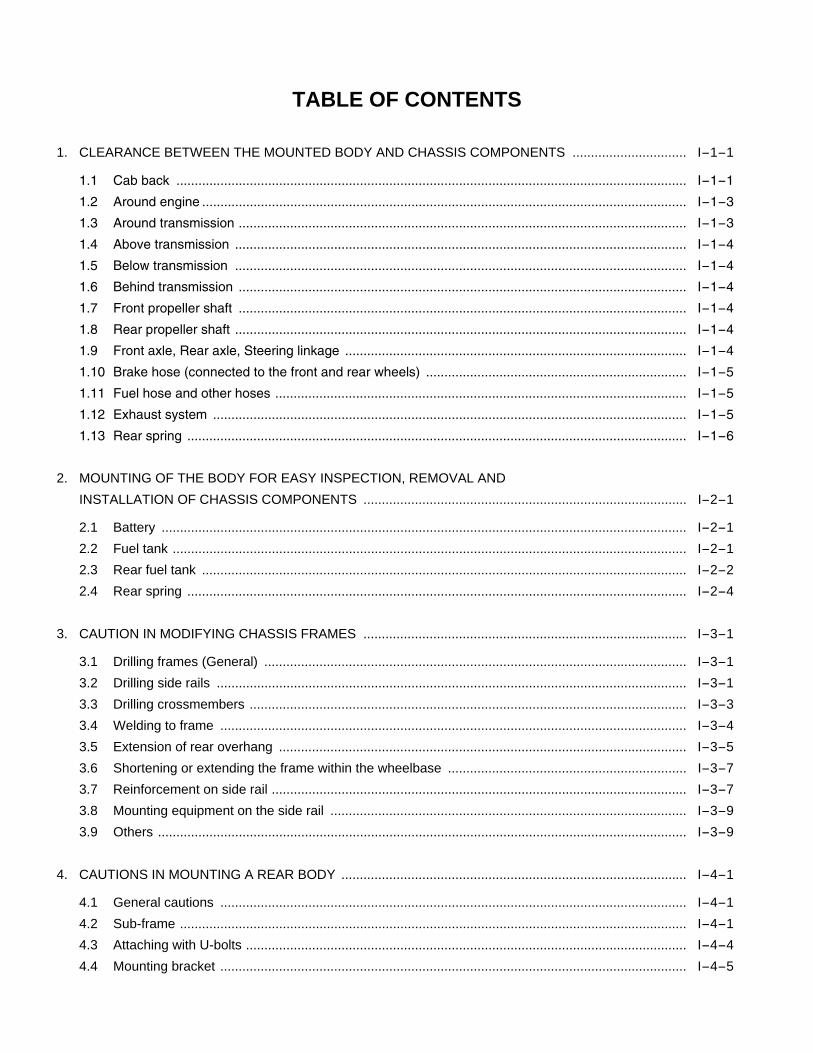
TABLE OF CONTENTS 1. CLEARANCE BETWEEN THE MOUNTED BODY AND CHASSIS COMPONENTS ............................... I-1-1
1.1 Cab back ........................................................................................................................................... I-1-1
1.2 Around engine .................................................................................................................................... I-1-3
1.3 Around transmission .......................................................................................................................... I-1-3
1.4 Above transmission ........................................................................................................................... I-1-4
1.5 Below transmission ........................................................................................................................... I-1-4
1.6 Behind transmission .......................................................................................................................... I-1-4
1.7 Front propeller shaft .......................................................................................................................... I-1-4
1.8 Rear propeller shaft ........................................................................................................................... I-1-4
1.9 Front axle, Rear axle, Steering linkage ............................................................................................. I-1-4
1.10 Brake hose (connected to the front and rear wheels) ....................................................................... I-1-5
1.11 Fuel hose and other hoses ................................................................................................................ I-1-5
1.12 Exhaust system ................................................................................................................................. I-1-5
1.13 Rear spring ........................................................................................................................................ I-1-6
2. MOUNTING OF THE BODY FOR EASY INSPECTION, REMOVAL AND
INSTALLATION OF CHASSIS COMPONENTS ........................................................................................ I-2-1
2.1 Battery ............................................................................................................................................... I-2-1 2.2 Fuel tank ............................................................................................................................................ I-2-1 2.3 Rear fuel tank .................................................................................................................................... I-2-2 2.4 Rear spring ........................................................................................................................................ I-2-4
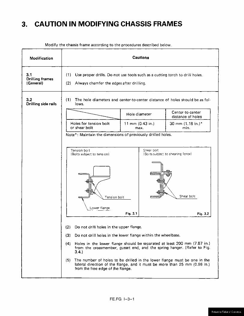
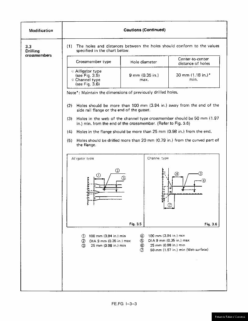
3. CAUTION IN MODIFYING CHASSIS FRAMES ........................................................................................ I-3-1
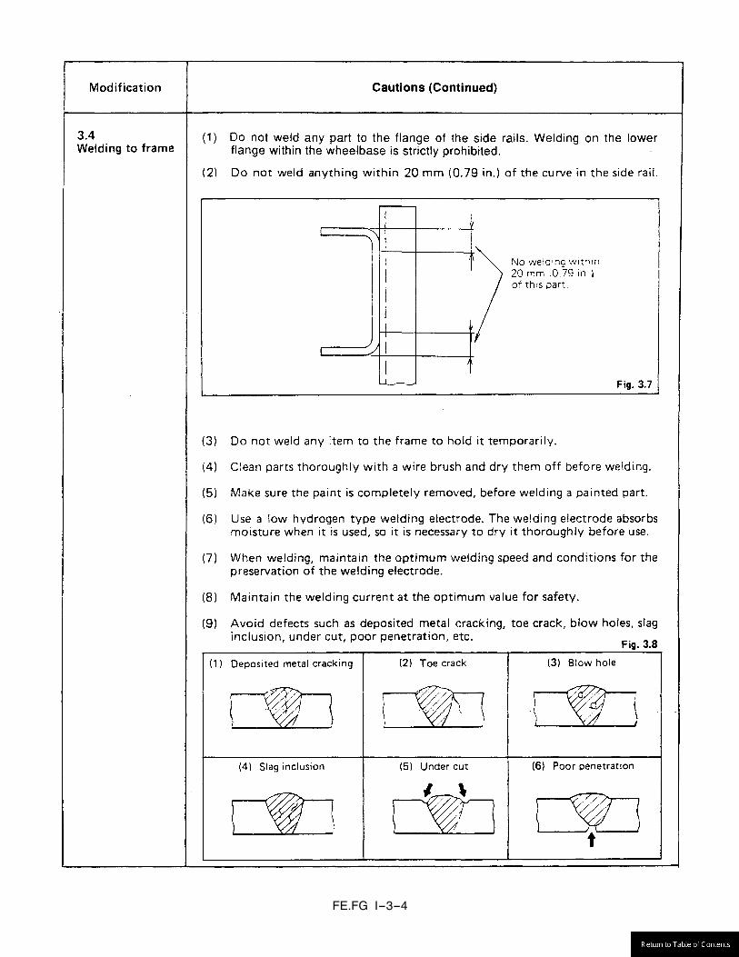
3.1 Drilling frames (General) ................................................................................................................... I-3-1 3.2 Drilling side rails ................................................................................................................................ I-3-1 3.3 Drilling crossmembers ....................................................................................................................... I-3-3 3.4 Welding to frame ............................................................................................................................... I-3-4 3.5 Extension of rear overhang ............................................................................................................... I-3-5 3.6 Shortening or extending the frame within the wheelbase ................................................................. I-3-7 3.7 Reinforcement on side rail ................................................................................................................. I-3-7 3.8 Mounting equipment on the side rail ................................................................................................. I-3-9 3.9 Others ................................................................................................................................................ I-3-9
4. CAUTIONS IN MOUNTING A REAR BODY .............................................................................................. I-4-1
4.1 General cautions ............................................................................................................................... I-4-1 4.2 Sub-frame .......................................................................................................................................... I-4-1 4.3 Attaching with U-bolts ........................................................................................................................ I-4-4 4.4 Mounting bracket ............................................................................................................................... I-4-5
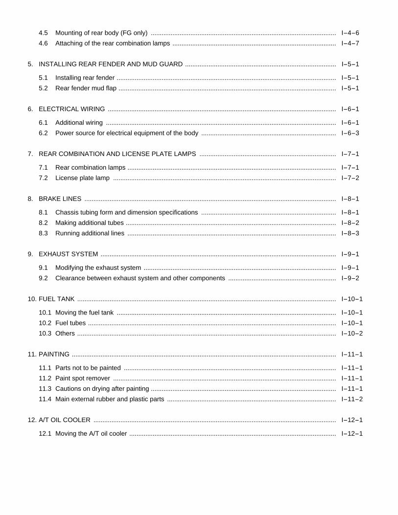
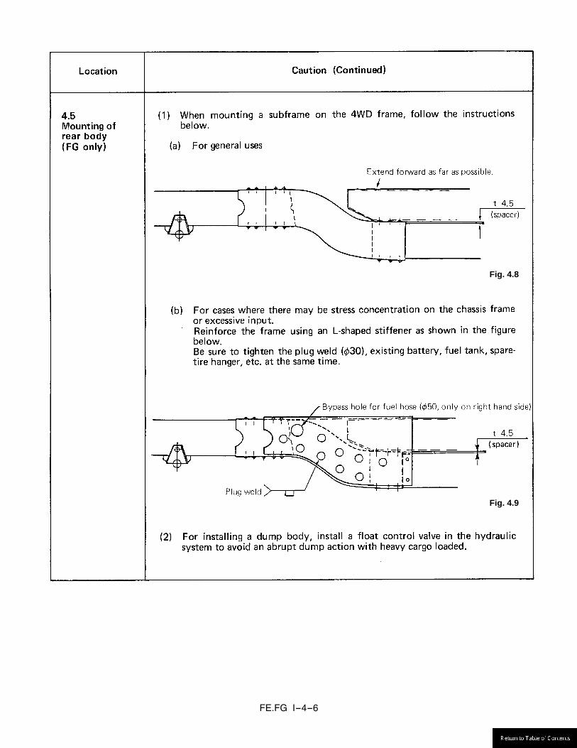
4.5 Mounting of rear body (FG only) ....................................................................................................... I-4-6 4.6 Attaching of the rear combination lamps ........................................................................................... I-4-7
5. INSTALLING REAR FENDER AND MUD GUARD .................................................................................... I-5-1
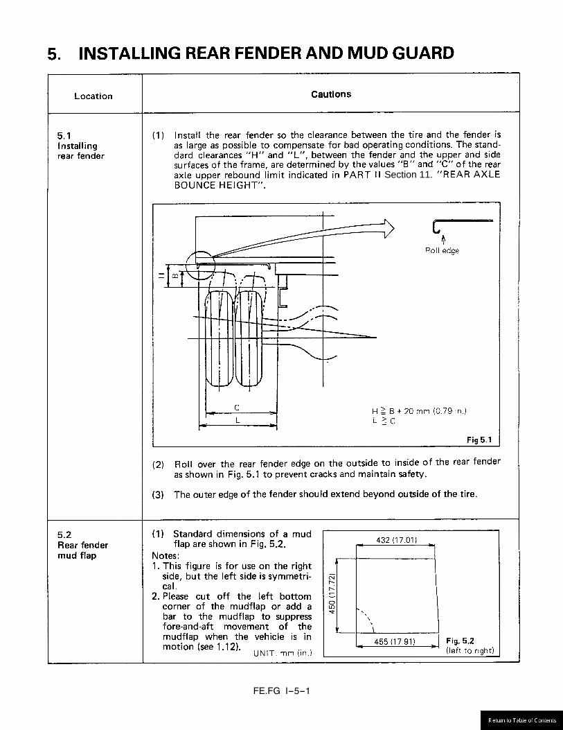
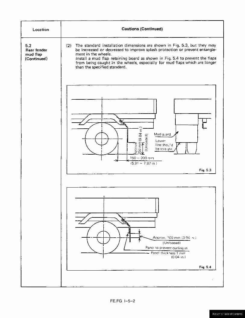
5.1 Installing rear fender .......................................................................................................................... I-5-1 5.2 Rear fender mud flap ......................................................................................................................... I-5-1
6. ELECTRICAL WIRING ............................................................................................................................... I-6-1
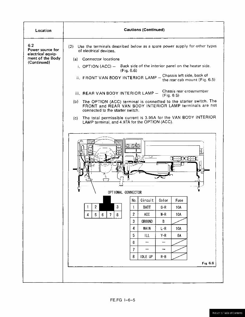
6.1 Additional wiring ................................................................................................................................ I-6-1 6.2 Power source for electrical equipment of the body ........................................................................... I-6-3
7. REAR COMBINATION AND LICENSE PLATE LAMPS ............................................................................ I-7-1
7.1 Rear combination lamps .................................................................................................................... I-7-1 7.2 License plate lamp ............................................................................................................................ I-7-2
8. BRAKE LINES ............................................................................................................................................ I-8-1
8.1 Chassis tubing form and dimension specifications ........................................................................... I-8-1 8.2 Making additional tubes ..................................................................................................................... I-8-2 8.3 Running additional lines .................................................................................................................... I-8-3
9. EXHAUST SYSTEM ................................................................................................................................... I-9-1
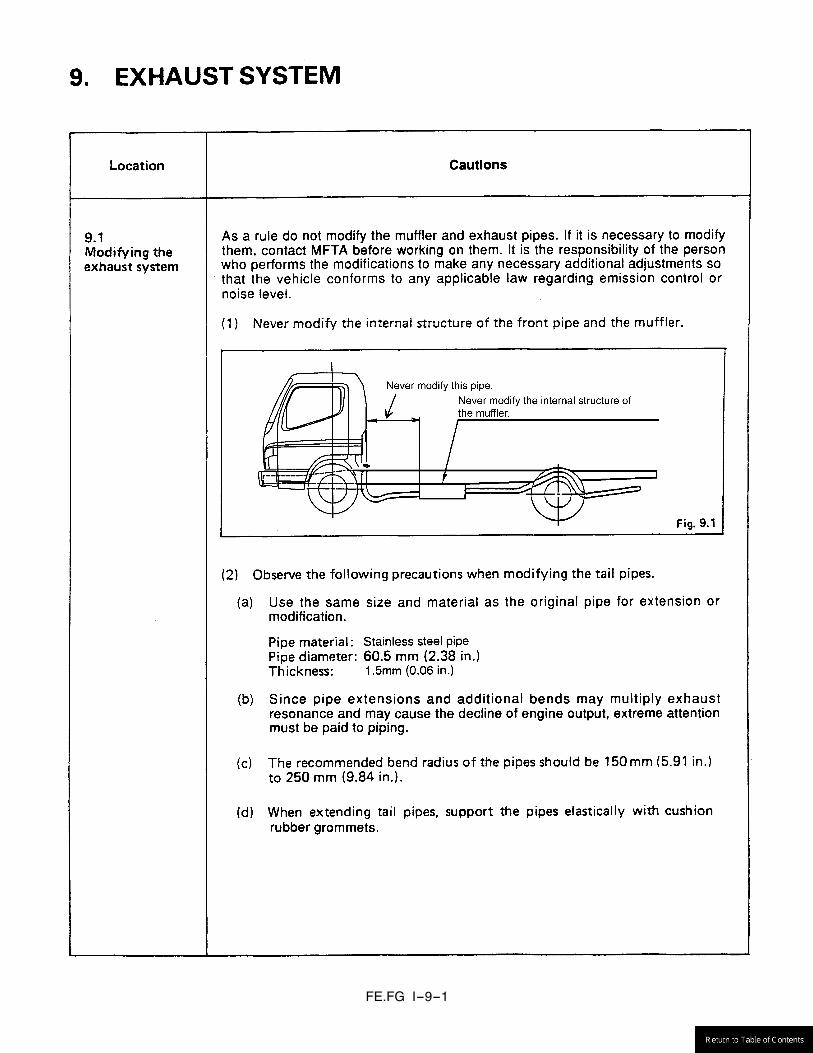
9.1 Modifying the exhaust system ........................................................................................................... I-9-1 9.2 Clearance between exhaust system and other components ............................................................ I-9-2
10. FUEL TANK ................................................................................................................................................ I-10-1
10.1 Moving the fuel tank .......................................................................................................................... I-10-1 10.2 Fuel tubes .......................................................................................................................................... I-10-1 10.3 Others ................................................................................................................................................ I-10-2
11. PAINTING ................................................................................................................................................... I-11-1
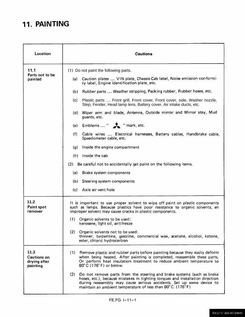
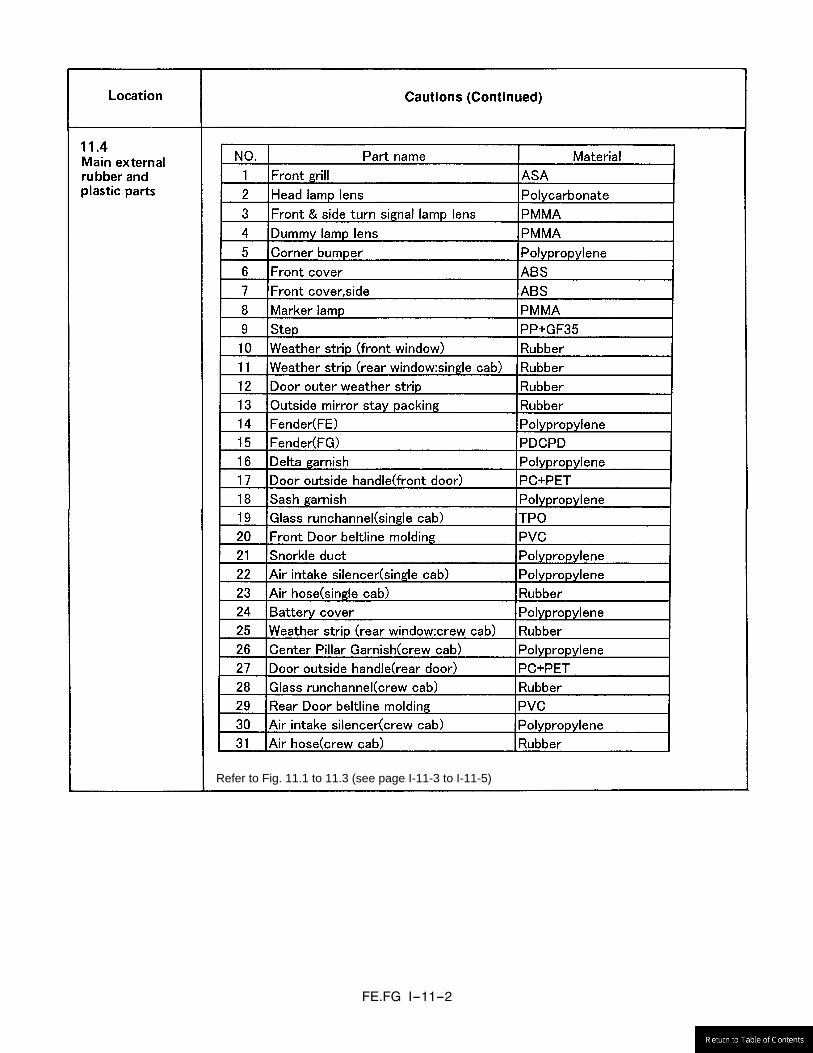
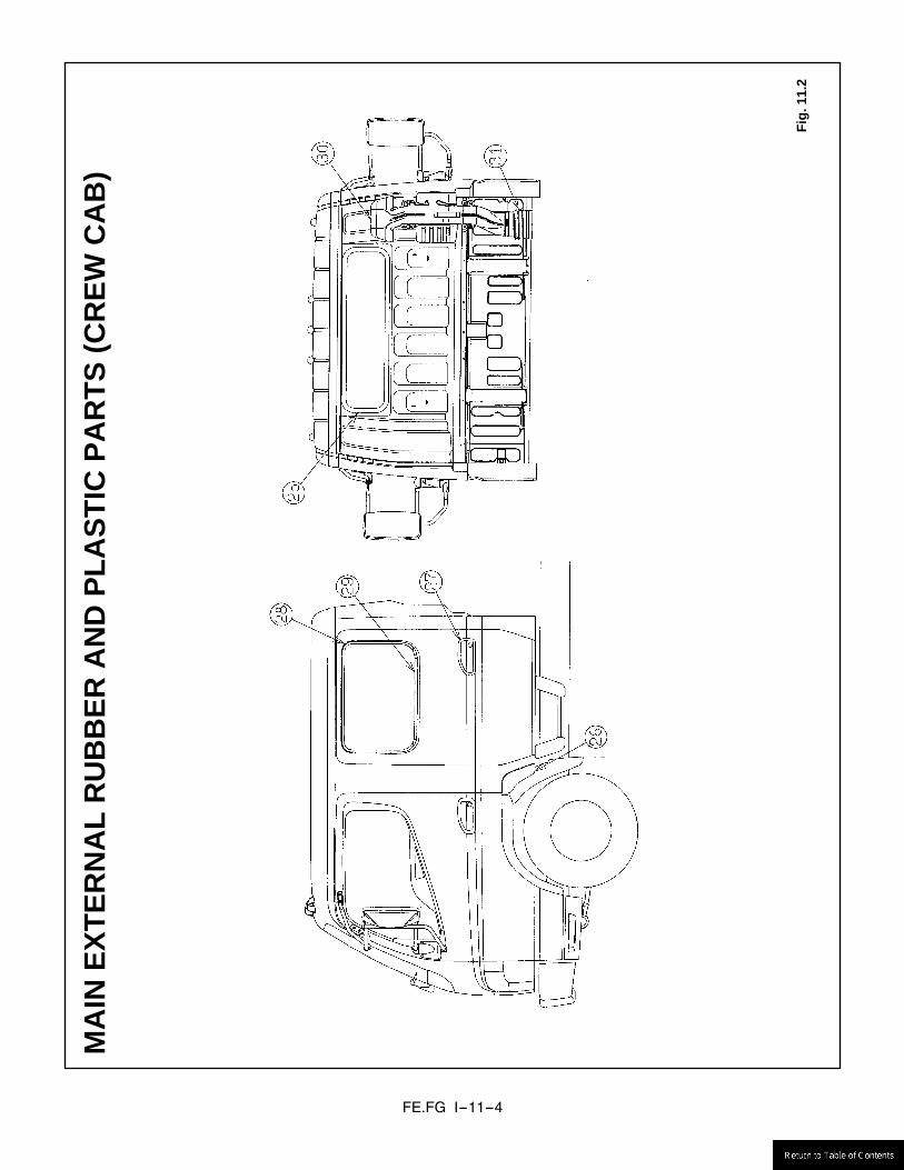
11.1 Parts not to be painted ...................................................................................................................... I-11-1 11.2 Paint spot remover ............................................................................................................................ I-11-1 11.3 Cautions on drying after painting ....................................................................................................... I-11-1 11.4 Main external rubber and plastic parts .............................................................................................. I-11-2
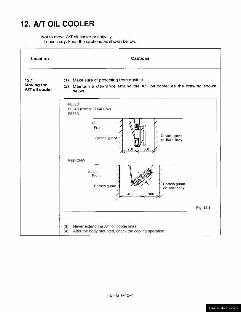
12. A/T OIL COOLER ....................................................................................................................................... I-12-1
12.1 Moving the A/T oil cooler ................................................................................................................... I-12-1

FE.FG I-1-1
Fig. 1.1
FE
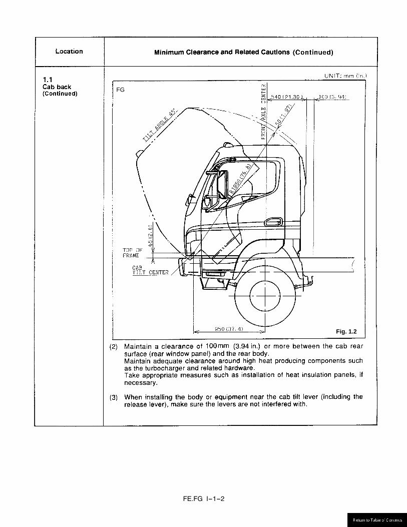
FE.FG I-1-2
Fig. 1.2
FG
FE.FG I-1-3
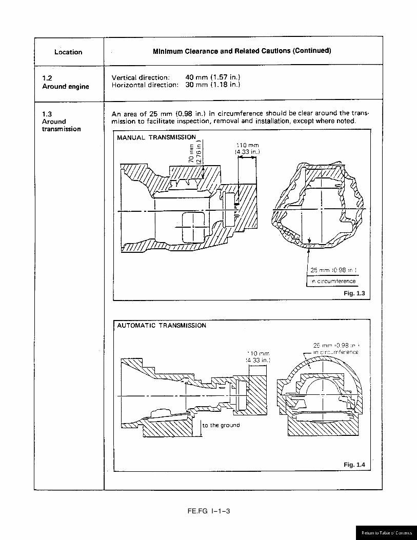
Fig. 1.4
Fig. 1.3
FE.FG I-1-4
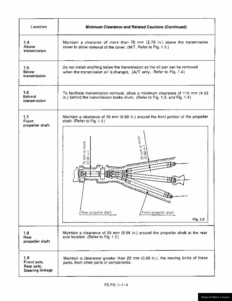
Fig. 1.5
FE.FG I-1-5
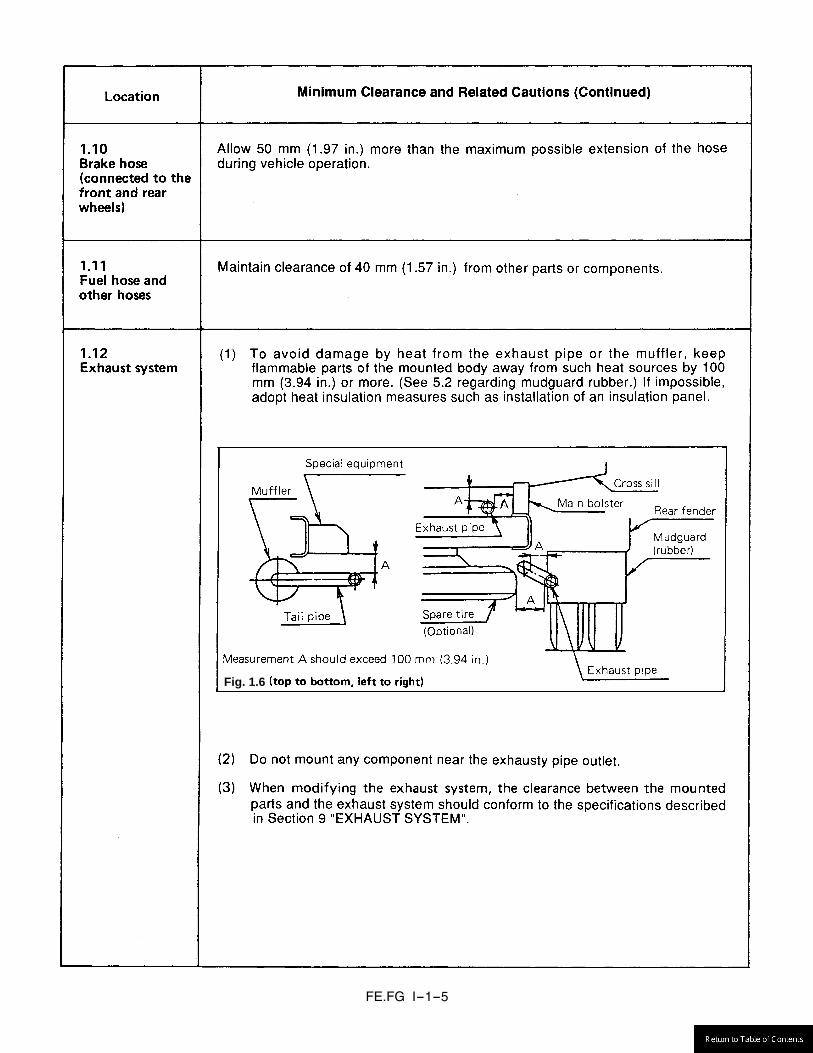
Fig. 1.6

FE.FG I-1-6
Fig. 1.7

FE.FG I-2-1

FE.FG I-2-2
Location Cautions (Continued)
2.3 Rear fuel tank
Use care when installing the rear fuel tank piping. Do not let it interfere with the body. Do not allow foreign material to enter the fuel tank and related parts. Install all fuel hoses so that there is no slack, broken parts and make sure that the hose is free to accept fuel. Hose that is too long may be shortened if required. The temporary rubber cap on the fuel tank filler frame pass through must be removed. Clip part number MH021308 must be reused. When inserting fuel filler hose MK517156, make sure that the hose is completely against the seat (spool) of the filler pipe. Install in accordance with the illustration printed below. Make sure there is no interference with the breather hose. Remove the two tie wraps that temporarily hold the breather hose in the shipping position. Insert more than 20 mm of the breather hose MK517155 to the filler end pipe and retain it suing clamp # MH021302. Position the breather hose using clamps MH020946 to points indicated in the illustration below. Secure breather hose to the filler pipe using tie wraps #ME292602 in two places. Refer to Fig. 2.3, Fig. 2.4 and indicated in PART II Section 12.4 “FE Series (Rear fuel tank)”. The fuel filler end must be attached to the rear body structure. The rear body structure must be strong enough to support the weight of all components. The filler pipe must not be allowed to project beyond the side of the body. The fuel filler pipe MUST be located at least 169 mm above the height of the upper truck frame flange. This will allow satisfactory fill speed. Attach the fuel cap tether. See PART II Section 12.4 “FE Series (Rear fuel tank)”. The air vent valve inclination must be approximately 25 degrees to vertical. Attach caution label MK518283 where it will be easy to see. Inspect the system and insure that all attaching hardware is secure. Make sure there are no leaks or restrictions.

FE.FG I-2-3
Location Cautions (Continued)
2.3 Rear fuel tank (Continued)
Part Tightening torque Remarks Screw of Clip 3.9 ± 1.0 [N·m] - Filler end 8 - 12 [N·m] With tether of filler cap
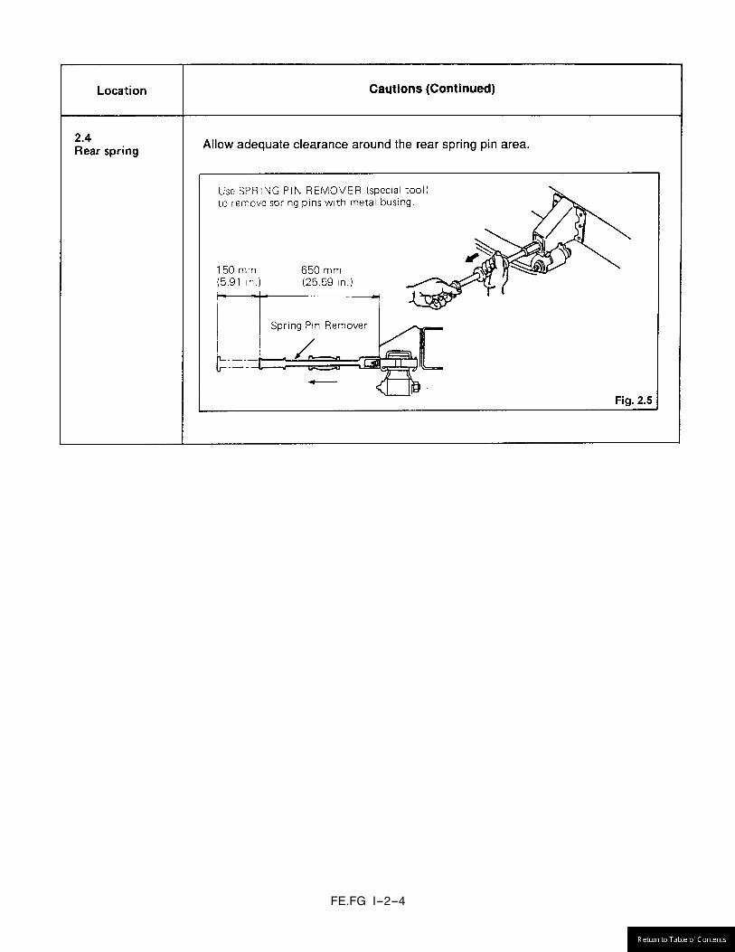
FE.FG I-2-4
FE.FG I-3-1

FE.FG I-3-2
No bolt holes in the upper and lower flange
A FE83D FE84D (except FE84DHW)FE85D
30 mm (1.18 in.)
FE84DHW FG84
20 mm (0.79 in.)
FE.FG I-3-3
FE.FG I-3-4
Fig. 1.5
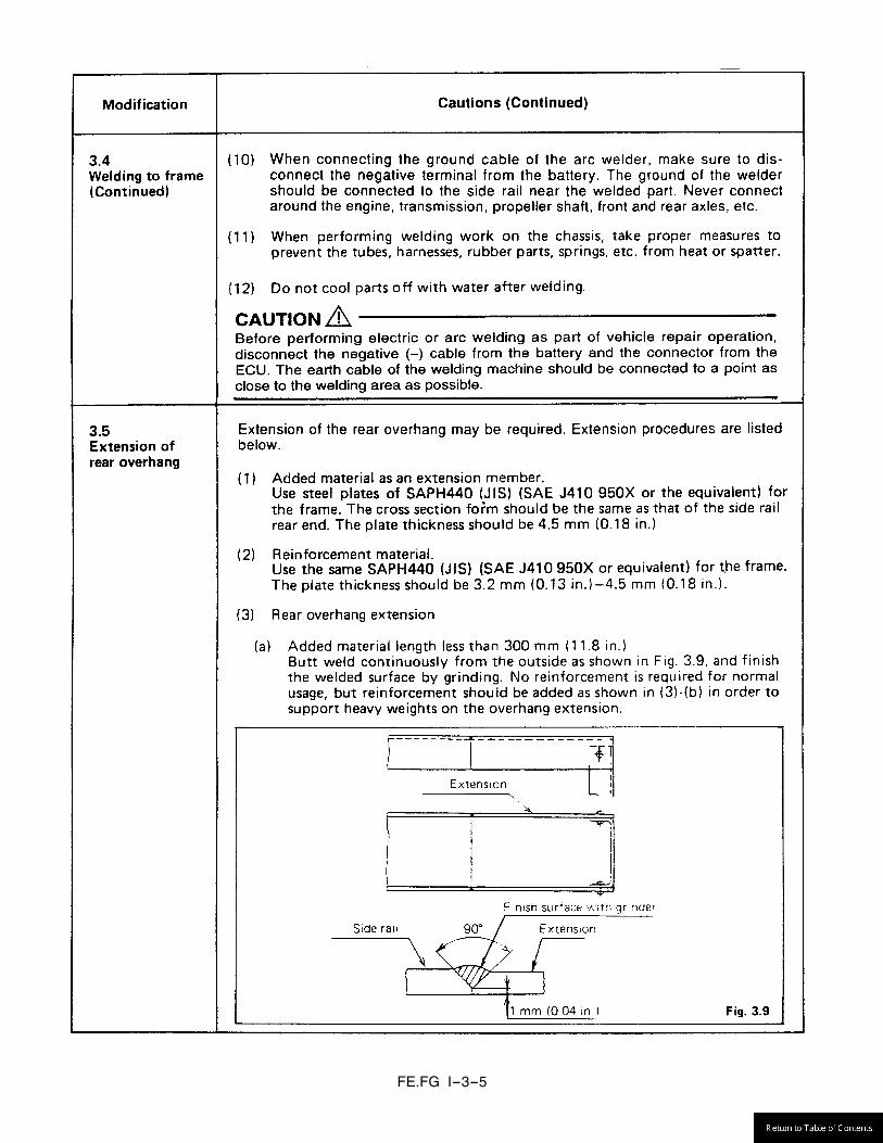
FE.FG I-3-5

FE.FG I-3-6

FE.FG I-3-7
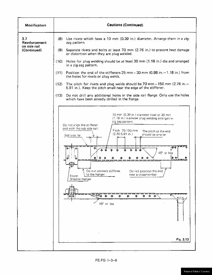
FE.FG I-3-8
FE.FG I-3-9

FE.FG I-4-1
(c) Modyfing brake hoses or vacuum lines. (Use MFTBC replacement partsonly.)

FE.FG I-4-2
(2)
Fig. 4.2
Fig. 4.2
Fig. 4.3
Fig. 4.2
Fig. 4.3

FE.FG I-4-3
Fig. 4.3, Fig. 4.4
Fig. 4.4
Fig. 4.2

FE.FG I-4-4
Fig. 4.5
Fig. 4.6
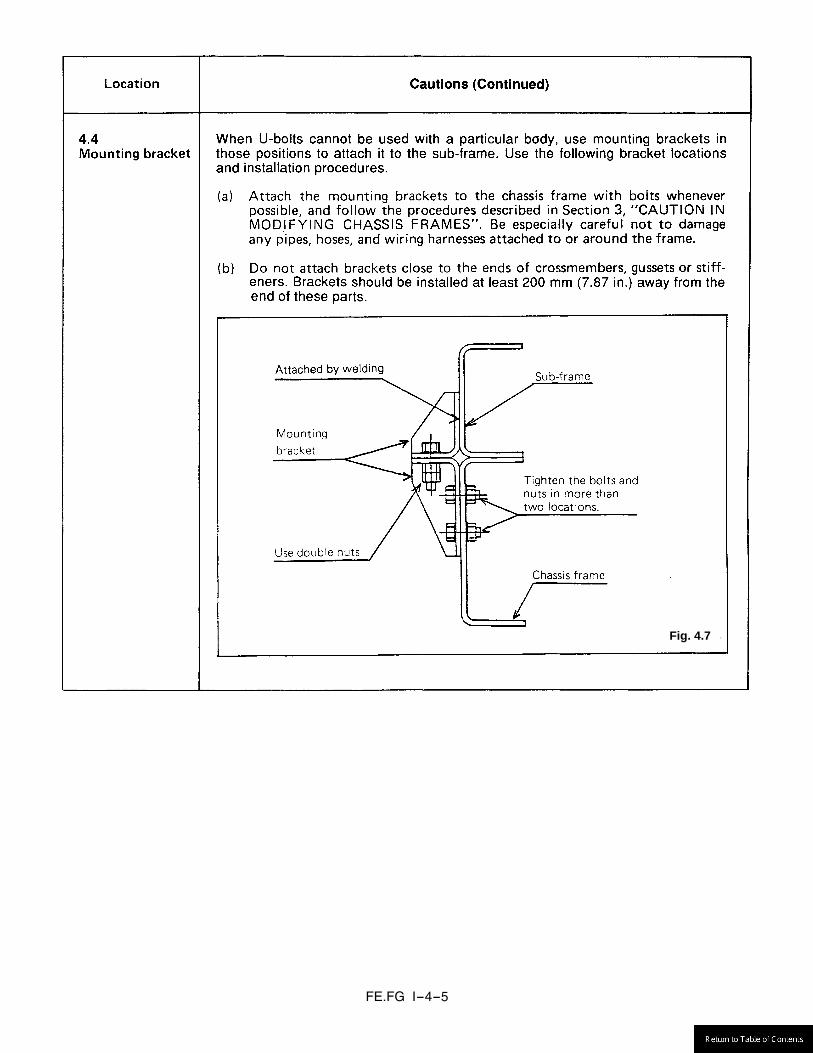
FE.FG I-4-5
Fig. 4.7
FE.FG I-4-6
Fig. 4.8
Fig. 4.9
FE.FG I-4-7
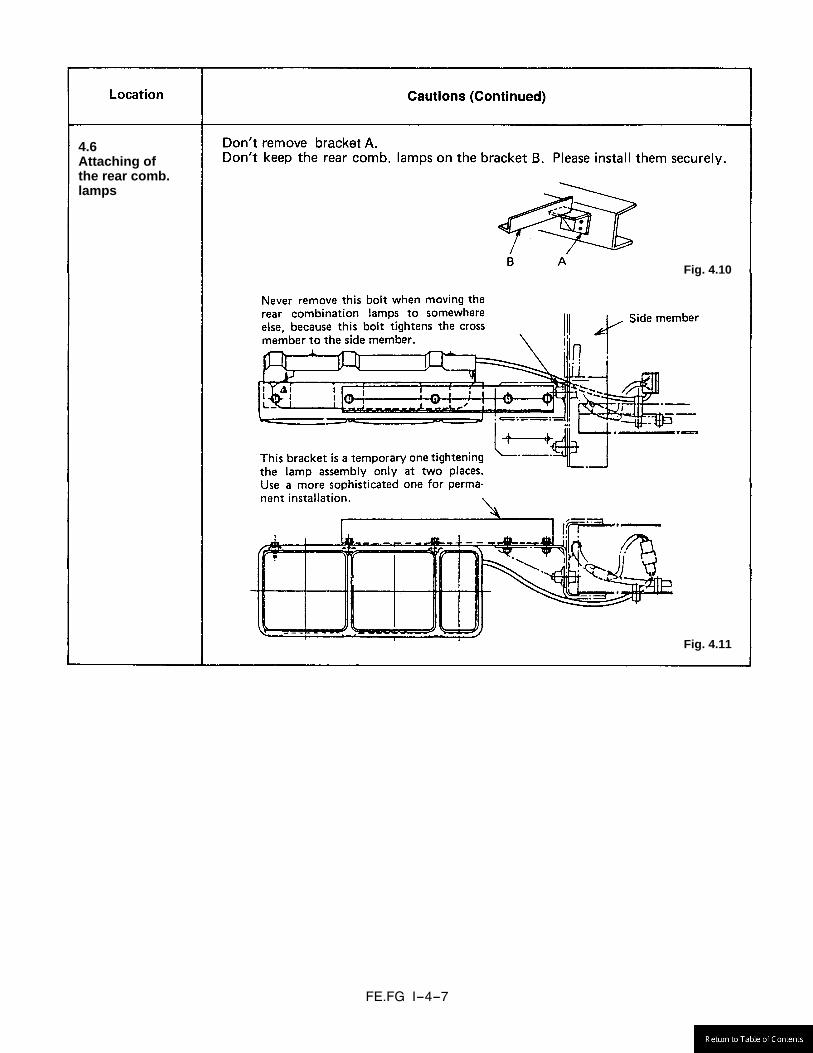
4.6 Attaching of the rear comb. lamps
Fig. 4.10
Fig. 4.11
FE.FG I-5-1
Section 11.
FE.FG I-5-2

FE.FG I-6-1

FE.FG I-6-2

FE.FG I-6-3

FE.FG I-6-4
FE.FG I-6-5

FE.FG I-6-6
Fuse Capacity Chart High-current fuse box
Fuse No. Main load Capacity FH1 Fuse box (S1, A1 to A5, M1 to M12) 60A FH2 Fuse box (B1 to B12) 60A FH3 Fuse box (B13 to B16) 40A FH5 Hydraulic booster 60A FH7 ABS motor 40A FH8 ABS solenoid 40A B25 Tail lamp 15A B27 Horn 10A B28 Air-conditioner 10A B29 Condenser fan 25A B30 Blower fan 30A B33 Van body dome light 10A B34 ATF cooler fan 20A B36 Engine electronic drive unit 20A
BATT1 Alternator 120A BATT2 Alternator 120A
ABS: Anti-lock brake system ATF: Automatic transmission fluid

FE.FG I-6-7
Fuse box
Fuse No. Main load Capacity A1 Cigar lighter 15A A2 Audio 10A A4 Opt (ACC) 10A B1 Stop lamp 15A B2 Meter 10A B3 Turn signal lamp 15A B4 Opt (B) 10A B5 Audio 10A B6 Cab lamp 10A B7 Power window (driver) 30A B8 Power window (assistant) 30A B9 Engine electronic control unit 20A
B11 Mirror heater 20A B12 Automatic transmission 10A B13 Tester 15A B14 Headlamp (HI) 20A B15 Headlamp (LH/LO) 20A B16 Headlamp (RH/LO) 20A M1 Backup lamp 10A M2 Meter 10A M3 Wiper 15A M4 Opt (M) 10A M5 Relay control 10A M6 Automatic transmission 10A M8 Exhaust brake 10A M9 Engine electronic control unit 5A
M11 ABS 10A S1 Starter 10A
Diagnosis fuse
Fuse No. Main load Capacity A/T Diagnosis 5A A/T Memory clear 10A ABS Diagnosis 5A ABS Memory clear 10A
Engin ECU Diagnosis 5A Engin ECU Memory clear 10A
ABS: Anti-lock brake system A/T: Automatic transmission ECU: Electronic control unit

FE.FG I-7-1
plate lamp and license plate, and then perform the installation.

FE.FG I-8-1
FE.FG I-8-2
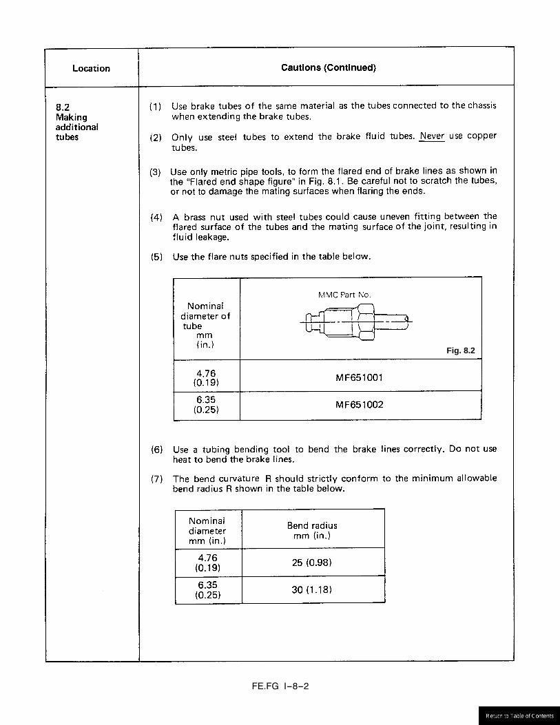
Fig. 8.2
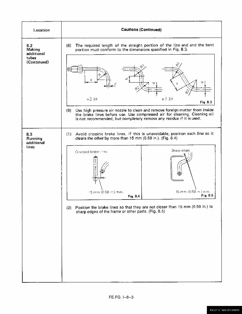
FE.FG I-8-3
FE.FG I-8-4

FE.FG I-8-5
FE.FG I-9-1

FE.FG I-9-2

FE.FG I-10-1
Fig. 10.1

FE.FG I-10-2
FE.FG I-11-1
11.2
Plastic parts .... Front grill, Front cover, Front cover, side, Washer nozzle,Step, Fender, Head lamp lens, Battery cover, Air intake ducts, etc.
Do not paint the following parts.
11.3

FE.FG I-11-3
Fig.
11.
1
MA
IN E
XTER
NA
L R
UB
BER
AN
D P
LAST
IC P
AR
TS
FE.FG I-11-2
Refer to Fig. 11.1 to 11.3 (see page I-11-3 to I-11-5)
FE.FG I-11-4
Fig.
11.
2
MA
IN E
XTER
NA
L R
UB
BER
AN
D P
LAST
IC P
AR
TS (C
REW
CA
B)
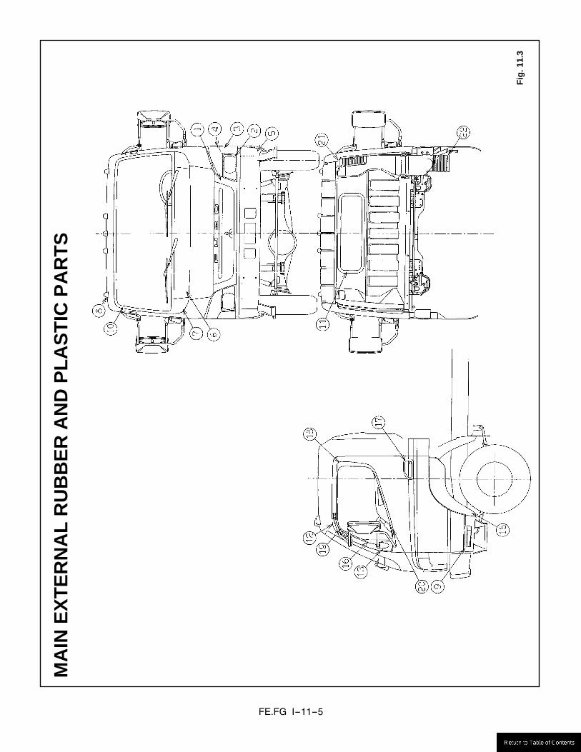
FE.FG I-11-5
Fig.
11.
3
MA
IN E
XTER
NA
L R
UB
BER
AN
D P
LAST
IC P
AR
TS
FE.FG I-12-1
(3) Never extend the A/T oil cooler lines. (4) After the body mounted, check the cooling operation.
Fig. 12.1
FE83D FE84D (except FE84DHW) FE85D
FE84DHW