2010 kenworth t440/t470 body builder manual
TRANSCRIPT
®
2010Kenworth T440/T470 Body Builder Manual
2010 EmissionsKenworth T440/T470 Body Builder Manual
T470/T440 Body Builder Manual Contents
iv12/09
SECTION 1: INTRODUCTION 1-1
SECTION 2: SAFETY AND COMPLIANCE 2-1SAFETY SIGNALS . . . . . . . . . . . . . . . . . . . . . . . . . . . . . . . . . . . . . . 2-1FEDERAL MOTOR VEHICLE SAFETYSTANDARDS COMPLIANCE . . . . . . . . . . . . 2-2
SECTION 3: DIMENSIONS 3-1DIMENSIONS . . . . . . . . . . . . . . . . . . . . . . . . . . . . . . . . . . . . . . . . . 3-1ABBREVIATIONS . . . . . . . . . . . . . . . . . . . . . . . . . . . . . . . . . . . . . . . 3-1TURNING RADIUS . . . . . . . . . . . . . . . . . . . . . . . . . . . . . . . . . . . . . . 3-1KENWORTH AXLE TRACK/TIRE WIDTH SUMMARY . . . . . . . . . . . . . . . . . . . . 3-4OVERALL DIMENSIONS . . . . . . . . . . . . . . . . . . . . . . . . . . . . . . . . . . . 3-5T470 FIXED GRILLE HOOD W/O EXTENDED FRONT FRAME . . . . . . . . . . . . . . . 3-6T440 DAYCAB . . . . . . . . . . . . . . . . . . . . . . . . . . . . . . . . . . . . . . . . . 3-7T470 FIXED GRILLE HOOD WITH EXTENDED FRONT FRAME . . . . . . . . . . . . . . 3-938” AEROCAB . . . . . . . . . . . . . . . . . . . . . . . . . . . . . . . . . . . . . . . . . 3-10RIDE HEIGHTS . . . . . . . . . . . . . . . . . . . . . . . . . . . . . . . . . . . . . . . . 3-12REAR SUSPENSION LAYOUTS . . . . . . . . . . . . . . . . . . . . . . . . . . . . . . . 3-14REYCO 79KB SINGLE REAR AXLE . . . . . . . . . . . . . . . . . . . . . . . . . . . . . 3-14REYCO 102 TANDEM REAR AXLE . . . . . . . . . . . . . . . . . . . . . . . . . . . . . . 3-15NEWAY AD 123 SINGLE REAR AXLE . . . . . . . . . . . . . . . . . . . . . . . . . . . . 3-16NEWAY AD 246 TANDEM SUSPENSION . . . . . . . . . . . . . . . . . . . . . . . . . . . 3-17HENDRICKSON PRIMAAX TANDEM SUSPENSION. . . . . . . . . . . . . . . . . . . . . 3-18HENDRICKSON HMX TANDEM SUSPENSION . . . . . . . . . . . . . . . . . . . . . . . 3-19HENDRICKSON RT TANDEM SUSPENSION. . . . . . . . . . . . . . . . . . . . . . . . . 3-20KENWORTH AG 380 TANDEM SUSPENSION . . . . . . . . . . . . . . . . . . . . . . . . 3-22KENWORTH AG 400/460 TANDEM SUSPENSION. . . . . . . . . . . . . . . . . . . . . . 3-23KENWORTH AG 400L TANDEM SUSPENSION . . . . . . . . . . . . . . . . . . . . . . . 3-24KENWORTH AG 460 TANDEM SUSPENSION . . . . . . . . . . . . . . . . . . . . . . . . 3-25CHALMERS 856-46 TANDEM SUSPENSION. . . . . . . . . . . . . . . . . . . . . . . . . 3-26PUSHER AXLES . . . . . . . . . . . . . . . . . . . . . . . . . . . . . . . . . . . . . . . 3-27PTO CLEARANCES . . . . . . . . . . . . . . . . . . . . . . . . . . . . . . . . . . . . . . 3-32
SECTION 4: EXHAUST AND AFTERTREATMENT 4-1EXHAUST AND AFTER-TREATMENT INFORMATION . . . . . . . . . . . . . . . . . . . . 4-1GENERAL GUIDELINES FOR DEF SYSTEM . . . . . . . . . . . . . . . . . . . . . . . . 4-3INSTALLATION REQUIREMENTS AND DIMENSIONS FOR DEF SYSTEM . . . . . . . . . 4-3MEASUREMENT REFERENCE POINTS . . . . . . . . . . . . . . . . . . . . . . . . . . . 4-4GENERAL EXHAUST INFORMATION . . . . . . . . . . . . . . . . . . . . . . . . . . . . 4-10EXHAUST INFORMATION . . . . . . . . . . . . . . . . . . . . . . . . . . . . . . . . . . 4-19
SECTION 5: FRAME LAYOUTS 5-1FRAME LAYOUTS . . . . . . . . . . . . . . . . . . . . . . . . . . . . . . . . . . . . . . . 5-1COMMON OPTIONAL COMPONENTS . . . . . . . . . . . . . . . . . . . . . . . . . . . . 5-2FRAME LAYOUT INDEX. . . . . . . . . . . . . . . . . . . . . . . . . . . . . . . . . . . . 5-4CHARTS . . . . . . . . . . . . . . . . . . . . . . . . . . . . . . . . . . . . . . . . . . . . 5-5
SECTION 6: BODY MOUNTING 6-1FRONT FRAME DIMENSIONS . . . . . . . . . . . . . . . . . . . . . . . . . . . . . . . . 6-1FRAME INFORMATION . . . . . . . . . . . . . . . . . . . . . . . . . . . . . . . . . . . . 6-2BODY MOUNTING USING BRACKETS. . . . . . . . . . . . . . . . . . . . . . . . . . . . 6-3MOUNTING HOLES . . . . . . . . . . . . . . . . . . . . . . . . . . . . . . . . . . . . . . 6-5BODY MOUNTING USING U–BOLTS . . . . . . . . . . . . . . . . . . . . . . . . . . . . . 6-6
T470/T440 Body Builder Manual Contents
v 12/09
SECTION 7: FRAME MODIFICATIONS 7-1FRAME MODIFICATIONS . . . . . . . . . . . . . . . . . . . . . . . . . . . . . . . . . . . 7-1MODIFYING FRAME LENGTH . . . . . . . . . . . . . . . . . . . . . . . . . . . . . . . . 7-2CHANGING WHEELBASE . . . . . . . . . . . . . . . . . . . . . . . . . . . . . . . . . . 7-3CROSSMEMBERS . . . . . . . . . . . . . . . . . . . . . . . . . . . . . . . . . . . . . . 7-5WELDING . . . . . . . . . . . . . . . . . . . . . . . . . . . . . . . . . . . . . . . . . . . 7-6TORQUE REQUIREMENTS. . . . . . . . . . . . . . . . . . . . . . . . . . . . . . . . . . 7-7
SECTION 8: ELECTRICAL 8-1ELECTRICAL . . . . . . . . . . . . . . . . . . . . . . . . . . . . . . . . . . . . . . . . . 8-1MULTIPLEX INSTRUMENTATION. . . . . . . . . . . . . . . . . . . . . . . . . . . . . . . 8-1ACCESSING GAUGES AND SWITCHES . . . . . . . . . . . . . . . . . . . . . . . . . . . 8-9TELLTALE SYMBOLS . . . . . . . . . . . . . . . . . . . . . . . . . . . . . . . . . . . . . 8-17SPARE RELAYS BODY BUILDER INSTALLED(FOR LOADS EXCEEDING 20 AMPS) . . . 8-23ADDITIONAL SPARE CIRCUITS . . . . . . . . . . . . . . . . . . . . . . . . . . . . . . . 8-25REMOTE PTO/THROTTLE HARNESS . . . . . . . . . . . . . . . . . . . . . . . . . . . . 8-27MULTIFUNCTION TURN SIGNAL STALK, CHASSIS NODE & CHASSIS LOAD CENTER . 8-28CHASSIS LOAD CENTER DIMENSIONS. . . . . . . . . . . . . . . . . . . . . . . . . . . 8-302010 ELECTRICAL HARDWARE . . . . . . . . . . . . . . . . . . . . . . . . . . . . . . . 8-31TRAILER CABLE CONNECTIONS . . . . . . . . . . . . . . . . . . . . . . . . . . . . . . 8-35FACTORY INSTALLED SNOW PLOW LIGHT WIRING . . . . . . . . . . . . . . . . . . . . 8-37
SECTION 9: ROUTING 9-1ROUTING . . . . . . . . . . . . . . . . . . . . . . . . . . . . . . . . . . . . . . . . . . . 9-1ROUTING REQUIREMENTS . . . . . . . . . . . . . . . . . . . . . . . . . . . . . . . . . 9-2
APPENDIX A: VEHICLE IDENTIFICATION A-1VEHICLE IDENTIFICATION LABELS . . . . . . . . . . . . . . . . . . . . . . . . . . . . . A-2
Figures
vi12/09
FIGURE 2-1: INCOMPLETE VEHICLE CERTIFICATION DOCUMENT . . . . . . . . . . 2-2FIGURE 2-2: LOCATIONS OF CERTIFICATION LABELS . . . . . . . . . . . . . . . . . 2-2FIGURE 2-3: WEST COAST MIRROR OAT SENSOR, . . . . . . . . . . . . . . . . . . . 2-6FIGURE 2-4: AERODYNAMIC MIRROR OAT SENSOR LOCATION. . . . . . . . . . . . 2-7FIGURE 2-5: INSTRUMENT CLUSTER FOR T440/T470 USED WITH
EPA2010 EMISSION COMPLIANT ENGINES. . . . . . . . . . . . . . . . 2-7FIGURE 3-1: PROSPECTOR TURN CIRCLE ANALYSIS . . . . . . . . . . . . . . . . . 3-3FIGURE 4-1: MEASUREMENT LOCATION OF DEF SUPPLY MODULE (PUMP). . . . . 4-4FIGURE 4-2: MEASUREMENT LOCATION OF DEF DOSING MODULE (INJECTOR) . . 4-4FIGURE 4-3: ORIENTATION OF DOSING MODULE . . . . . . . . . . . . . . . . . . . 4-5FIGURE 4-4: RH UNDER CAB EXHAUST WITH SMALL, MEDIUM, OR LARGE TANKS. 4-5FIGURE 4-5: VERTICAL EXHAUST WITH SMALL, MEDIUM, OR LARGE TANKS. . . . . 4-6FIGURE 4-6: RH UNDER CAB EXHAUST WITH CLEAR BACK OF CAB TANK. . . . . . 4-7FIGURE 4-7: VERTICAL WITH CLEAR BACK OF CAB TANK . . . . . . . . . . . . . . . 4-8FIGURE 4-8: ROUTING DEF LINES AND DEF TRAP . . . . . . . . . . . . . . . . . . . 4-9FIGURE 4-9: SUPPLY MODULE ALLOWED CLOCKING ANGLES . . . . . . . . . . . . 4-9FIGURE 4-10: ISOMETRIC VIEW OF RIGHT HAND UNDER DPF AND SCR
WITH SINGLE SOC TAILPIPE . . . . . . . . . . . . . . . . . . . . . . . . 4-11FIGURE 4-11: TOP VIEW OF RIGHT HAND UNDER DPF AND SCR
WITH SINGLE SOC TAILPIPE . . . . . . . . . . . . . . . . . . . . . . . . 4-11FIGURE 4-12: RIGHT VIEW OF RIGHT HAND UNDER DPF AND SCR
WITH SINGLE SOC TAILPIPE . . . . . . . . . . . . . . . . . . . . . . . . 4-12FIGURE 4-13: BACK VIEW OF RIGHT HAND UNDER DPF AND SCR
WITH SINGLE SOC TAILPIPE . . . . . . . . . . . . . . . . . . . . . . . . 4-12FIGURE 4-14: ISOMETRIC VIEW OF RIGHT HAND UNDER DPF AND SCR
WITH SINGLE BACK OF CAB TAILPIPE . . . . . . . . . . . . . . . . . . 4-13FIGURE 4-15: TOP VIEW OF RIGHT HAND UNDER DPF AND SCR
WITH SINGLE BACK OF CAB TAILPIPE . . . . . . . . . . . . . . . . . . 4-13FIGURE 4-16: RIGHT VIEW OF RIGHT HAND UNDER DPF AND SCR
WITH SINGLE BACK OF CAB TAILPIPE . . . . . . . . . . . . . . . . . . 4-14FIGURE 4-17: BACK VIEW OF RIGHT HAND UNDER DPF AND SCR
WITH SINGLE BACK OF CAB TAILPIPE . . . . . . . . . . . . . . . . . . 4-14FIGURE 4-18: ISOMETRIC VIEW OF VERTICAL DPF AND SCR . . . . . . . . . . . . . 4-15FIGURE 4-19: TOP VIEW OF VERTICAL DPF AND SCR . . . . . . . . . . . . . . . . . 4-15FIGURE 4-20: RIGHT VIEW OF VERTICAL DPF AND SCR . . . . . . . . . . . . . . . . 4-16FIGURE 4-21: BACK VIEW OF VERTICAL DPF AND SCR . . . . . . . . . . . . . . . . 4-16FIGURE 4-22: ISOMETRIC VIEW OF RIGHT HAND UNDER DPF AND SCR ON
AEROCAB WITH SINGLE SOC TAILPIPE. . . . . . . . . . . . . . . . . . 4-17FIGURE 4-23: TOP VIEW OF RIGHT HAND UNDER DPF AND SCR ON
AEROCAB WITH SINGLE SOC TAILPIPE. . . . . . . . . . . . . . . . . . 4-17FIGURE 4-24: RIGHT VIEW OF RIGHT HAND UNDER DPF AND SCR ON
AEROCAB WITH SINGLE SOC TAILPIPE. . . . . . . . . . . . . . . . . . 4-17FIGURE 4-25: BACK VIEW OF RIGHT HAND UNDER DPF AND SCR ON
AEROCAB WITH SINGLE SOC TAILPIPE. . . . . . . . . . . . . . . . . . 4-18FIGURE 5-1: DEF TANK DIMENSIONS. . . . . . . . . . . . . . . . . . . . . . . . . . . 5-3FIGURE 6-1: MINIMUM CLEARANCE BETWEEN TOP OF REAR TIRES
AND BODY STRUCTURE OVERHANG.. . . . . . . . . . . . . . . . . . . 6-2FIGURE 6-2: MINIMUM BACK OF CAB CLEARANCE . . . . . . . . . . . . . . . . . . 6-3FIGURE 6-3: SPACER BETWEEN FRAME SILL AND BODY RAIL . . . . . . . . . . . . 6-4FIGURE 6-4: HIGH COMPRESSION SPRING. . . . . . . . . . . . . . . . . . . . . . . 6-4 FIGURE 6-5: RUBBER SPACER BETWEEN BRACKETS BETWEEN THE
MOUNTING BOLT AND UPPER BRACKET . . . . . . . . . . . . . . . . . 6-4
vii 12/09
Figures
FIGURE 6-6: CROSSMEMBER-GUSSET HOLE PATTERN REQUIREMENTS.. . . . . . 6-5FIGURE 6-7: ACCEPTABLE U-BOLT MOUNTING WITH WOOD AND
FABRICATED SPACERS. . . . . . . . . . . . . . . . . . . . . . . . . . . 6-6FIGURE 6-8: CLEARANCE SPACE FOR AIR LINES AND CABLES . . . . . . . . . . . 6-7FIGURE 6-9: EXAMPLE OF FISHPLATE BRACKET AT REAR END OF BODY,
USED WITH U-BOLTS . . . . . . . . . . . . . . . . . . . . . . . . . . . . 6-8FIGURE 7-1: DETAIL OF FRAME EXTENSION AND JOINT WELDING. . . . . . . . . . 7-2FIGURE 7-2: FRAME INSERT . . . . . . . . . . . . . . . . . . . . . . . . . . . . . . . 7-3FIGURE 7-3: COMPARISON OF ORIGINAL, SHORTENED, AND
EXTENDED WHEELBASES.. . . . . . . . . . . . . . . . . . . . . . . . . 7-4FIGURE 7-4: CROSSMEMBER ADDED WHEN DISTANCE
EXCEEDS 60 INCHES (1524 MM). . . . . . . . . . . . . . . . . . . . . . 7-5FIGURE 8-1: KENWORTH T440/T470 DASH . . . . . . . . . . . . . . . . . . . . . . . 8-2FIGURE 8-2: DIESEL EXHAUST FLUID GAUGE . . . . . . . . . . . . . . . . . . . . . 8-2FIGURE 8-3: MULTIPLEXED INSTRUMENTATION BLOCK DIAGRAM.. . . . . . . . . . 8-3FIGURE 8-4: CECU LOCATION. . . . . . . . . . . . . . . . . . . . . . . . . . . . . . . 8-4FIGURE 8-5: INSTRUMENT CLUSTER COMPONENTS . . . . . . . . . . . . . . . . . 8-5FIGURE 8-6: CVSG GAUGES . . . . . . . . . . . . . . . . . . . . . . . . . . . . . . . 8-6FIGURE 8-7: FIREWALL AIR JUNCTION BLOCK (VIEW FROM INSIDE OF CAB) . . . . 8-7FIGURE 8-8: AIR FILTER RESTRICTION SENSOR ON FIREWALL
AIR JUNCTION BLOCK (VIEW FROM ENGINE) . . . . . . . . . . . . . . 8-7FIGURE 8-9: FUEL FILTER RESTRICTION PRESSURE GAUGE SENSOR LOCATION
(TYPICAL) . . . . . . . . . . . . . . . . . . . . . . . . . . . . . . . . . . 8-8FIGURE 8-10: TELLTALE SYMBOL STANDARD CARDS . . . . . . . . . . . . . . . . . . 8-17FIGURE 8-11: BLANK TELLTALE CARD . . . . . . . . . . . . . . . . . . . . . . . . . . 8-18FIGURE 8-12: TELLTALE ICONS . . . . . . . . . . . . . . . . . . . . . . . . . . . . . . 8-19FIGURE 8-13: KENWORTH SPARE SWITCHES . . . . . . . . . . . . . . . . . . . . . . 8-20FIGURE 8-14: SPARE SWITCH HARNESS . . . . . . . . . . . . . . . . . . . . . . . . . 8-21FIGURE 8-15: SPECIALTY SWITCHES . . . . . . . . . . . . . . . . . . . . . . . . . . . 8-22FIGURE 8-16: SPARE RELAY CONNECTORS . . . . . . . . . . . . . . . . . . . . . . . 8-23FIGURE 8-17: SPARE RELAY HARNESSES . . . . . . . . . . . . . . . . . . . . . . . . 8-24FIGURE 8-18: SPARE BULLET CONNECTORS . . . . . . . . . . . . . . . . . . . . . . 8-25FIGURE 8-19: SPARE PIGTAIL CONNECTOR . . . . . . . . . . . . . . . . . . . . . . . 8-26FIGURE 8-21: CHASSIS POWER DISTRIBUTION CENTER DIMENSIONS . . . . . . . . 8-30FIGURE 8-22: DAYCAB HARDWARE LOCATIONS . . . . . . . . . . . . . . . . . . . . . 8-31FIGURE 8-23: AEROCAB STANDARD HARDWARE LOCATIONS . . . . . . . . . . . . . 8-31FIGURE 8-25: CHASSIS NODE DIMENSIONS . . . . . . . . . . . . . . . . . . . . . . . 8-32FIGURE 8-25: SAE J560 TRAILER CONNECTOR . . . . . . . . . . . . . . . . . . . . . . . FIGURE 8-26: ISO 3731 TRAILER CONNECTOR . . . . . . . . . . . . . . . . . . . . . 8-35FIGURE 8-27: JUNCTION BOX . . . . . . . . . . . . . . . . . . . . . . . . . . . . . . . 8-36FIGURE 8-31: SNOW PLOW ICON . . . . . . . . . . . . . . . . . . . . . . . . . . . . . 8-37FIGURE 8-32: CIRCUIT LOCATION . . . . . . . . . . . . . . . . . . . . . . . . . . . . . 8-37FIGURE 9-1: CLAMP AND BUTTERFLY CLAMP . . . . . . . . . . . . . . . . . . . . . 9-1FIGURE 9-2: BUTTERFLY TIE . . . . . . . . . . . . . . . . . . . . . . . . . . . . . . . 9-1FIGURE 9-3: TIE STRAP . . . . . . . . . . . . . . . . . . . . . . . . . . . . . . . . . . 9-1FIGURE 9-4: HEAVY DUTY (HD) MOUNT.. . . . . . . . . . . . . . . . . . . . . . . . . 9-2FIGURE 9-5: DEFINITION OF MEASUREMENTS. . . . . . . . . . . . . . . . . . . . . 9-4FIGURE A-1: VEHICLE IDENTIFICATION NUMBER (VIN). . . . . . . . . . . . . . . . . A-1FIGURE A-2: DRIVERS DOOR AND DOOR FRAME LABELS . . . . . . . . . . . . . . A-2FIGURE A-4: FRONT AXLE IDENTIFICATION. . . . . . . . . . . . . . . . . . . . . . . A-4FIGURE A-5: REAR AXLE IDENTIFICATION . . . . . . . . . . . . . . . . . . . . . . . A-4
viii12/09
Tables
TABLE 3-1: ABBREVIATIONS USED . . . . . . . . . . . . . . . . . . . . . . . . . . . . 3-1TABLE 3-2: TURNING RADIUS. . . . . . . . . . . . . . . . . . . . . . . . . . . . . . . 3-1TABLE 3-3: AXLE TRACK. . . . . . . . . . . . . . . . . . . . . . . . . . . . . . . . . . 3-4TABLE 3-4: RIDE HEIGHTS IN INCHES . . . . . . . . . . . . . . . . . . . . . . . . . . 3-12TABLE 3-5: REAR SUSPENSION OPTIONS . . . . . . . . . . . . . . . . . . . . . . . . 3-14TABLE 3-6: REAR SUSPENSION OPTIONS . . . . . . . . . . . . . . . . . . . . . . . . 3-15TABLE 3-7: REAR SUSPENSION OPTIONS . . . . . . . . . . . . . . . . . . . . . . . . 3-16TABLE 3-8: REAR SUSPENSION OPTIONS . . . . . . . . . . . . . . . . . . . . . . . . 3-17TABLE 3-9: REAR SUSPENSION OPTIONS . . . . . . . . . . . . . . . . . . . . . . . . 3-18TABLE 3-10: REAR SUSPENSION OPTIONS . . . . . . . . . . . . . . . . . . . . . . . . 3-19TABLE 3-11: REAR SUSPENSION OPTIONS . . . . . . . . . . . . . . . . . . . . . . . . 3-20TABLE 3-13: REAR SUSPENSION OPTIONS . . . . . . . . . . . . . . . . . . . . . . . . 3-22TABLE 3-14: REAR SUSPENSION OPTIONS . . . . . . . . . . . . . . . . . . . . . . . . 3-23TABLE 3-15: REAR SUSPENSION OPTIONS . . . . . . . . . . . . . . . . . . . . . . . . 3-24TABLE 3-16: REAR SUSPENSION OPTIONS . . . . . . . . . . . . . . . . . . . . . . . . 3-25TABLE 3-17: REAR SUSPENSION OPTIONS . . . . . . . . . . . . . . . . . . . . . . . . 3-26TABLE 3-18: GROUND CLEARANCE FOR FUEL TANKS. . . . . . . . . . . . . . . . . . 3-29TABLE 3-19: GROUND CLEARANCE FOR BATTERY BOXES . . . . . . . . . . . . . . . 3-30TABLE 3-20: GROUND CLEARANCE FOR BATTERY BOXES . . . . . . . . . . . . . . . 3-31TABLE 5-1: ABBREVIATIONS . . . . . . . . . . . . . . . . . . . . . . . . . . . . . . . 5-1TABLE 5-2: FUEL TANK OVERALL LENGTH (IN) . . . . . . . . . . . . . . . . . . . . . 5-2TABLE 5-3: BATTERY BOX CENTERFRAME LENGTHS (IN) . . . . . . . . . . . . . . . 5-2TABLE 5-4: DEF TANKS SYSTEMS . . . . . . . . . . . . . . . . . . . . . . . . . . . . 5-3TABLE 6-1: SINGLE STEEL RAILS. . . . . . . . . . . . . . . . . . . . . . . . . . . . . 6-2TABLE 6-2: INSERTED STEEL RAILS . . . . . . . . . . . . . . . . . . . . . . . . . . . 6-2TABLE 7-1: CUSTOMARY GRADE 8 UNF OR UNC. . . . . . . . . . . . . . . . . . . . . 7-7TABLE 7-2: U.S. CUSTOMARY – GRADE 8. METRIC CLASS 10.9 . . . . . . . . . . . . 7-7TABLE 8-1: TELLTALES POSITION AND COLOR . . . . . . . . . . . . . . . . . . . . . 8-18TABLE 8-3: CHASSIS NODE GUIDELINE . . . . . . . . . . . . . . . . . . . . . . . . . 8-28TABLE 8-4: WIRE NUMBER GENERAL CATEGORIES . . . . . . . . . . . . . . . . . . 8-33TABLE 8-6: SAE J560 CONNECTOR. . . . . . . . . . . . . . . . . . . . . . . . . . . . 8-34TABLE 8-7: ISO 3731 CONNECTOR . . . . . . . . . . . . . . . . . . . . . . . . . . . . 8-35TABLE 9-1: EXHAUST – SYSTEM CLEARANCE . . . . . . . . . . . . . . . . . . . . . 9-4TABLE A-1: MODEL YEAR (CODE) DESIGNATIONS. . . . . . . . . . . . . . . . . . . . A-1
Section 1Introduction
12/09 1-1
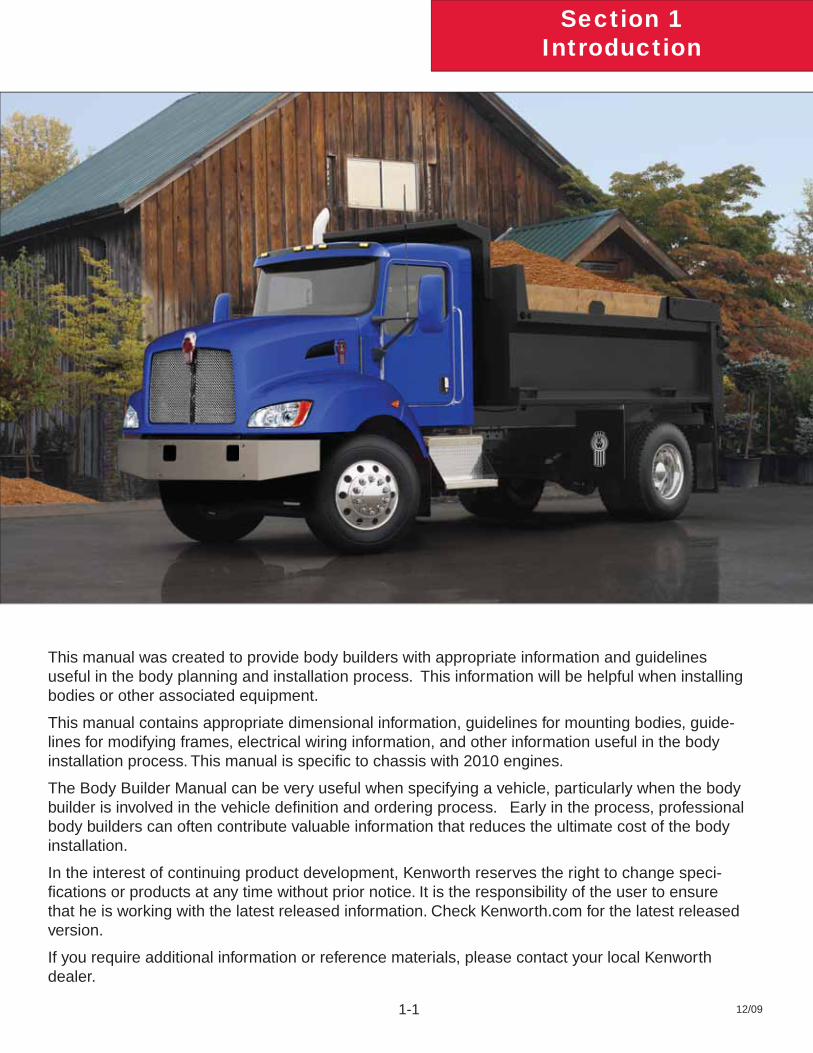
This manual was created to provide body builders with appropriate information and guidelines useful in the body planning and installation process. This information will be helpful when installing bodies or other associated equipment.
This manual contains appropriate dimensional information, guidelines for mounting bodies, guide-lines for modifying frames, electrical wiring information, and other information useful in the body installation process. This manual is specifi c to chassis with 2010 engines.
The Body Builder Manual can be very useful when specifying a vehicle, particularly when the body builder is involved in the vehicle defi nition and ordering process. Early in the process, professional body builders can often contribute valuable information that reduces the ultimate cost of the body installation.
In the interest of continuing product development, Kenworth reserves the right to change speci-fi cations or products at any time without prior notice. It is the responsibility of the user to ensure that he is working with the latest released information. Check Kenworth.com for the latest released version.
If you require additional information or reference materials, please contact your local Kenworth dealer.
Section 2Safety & Compliance
12/09 2-1
SAFETY SIGNALSWe’ve put a number of alerting messages in this book. Please read and follow them. They are there for your protection and information. These alerting messages can help you avoid injury to yourself or others and help prevent costly dam-age to the vehicle.
Key symbols and “signal words” are used to indicate what kind of message is going to follow. Pay special attention to comments prefaced by “WARNING”, “CAUTION”, and “NOTE.” Please don’t ignore any of these alerts.
Warnings, cautions, and notes
When you see this word and symbol, the message that follows is especially vital. It signals a potentially hazardous situation which, if not avoided, could result in death or serious injury. This message will tell you what the hazard is, what can happen if you don’t heed the warning, and how to avoid it.
Example:
WARNING! Be sure to use a circuit breaker designed to meet liftgate amperage requirements. An incor-rectly specifi ed circuit breaker could result in a electrical overload or fi re situation. Follow the liftgate installation instructions and use a circuit breaker with the recommended capacity.
Signals a potentially hazardous situation which, if not avoided, could result in minor or mod-erate injury or damage to the vehicle.
Example:
CAUTION: Never use a torch to make a hole in the rail. Use the appropriate drill bit.
Provides general information: for example, the note could warn you on how to avoid damaging your vehicle or how to drive the vehicle more effi ciently.
Example:
Note: Be sure to provide maintenance access to the battery box and fuel tank fi ll neck.
Please take the time to read these messages when you see them, and remember:
WARNINGIndicates a potentially hazardous situation which, if not avoided, could result in death or serious injury.
CAUTIONSignals a potentially hazardous situation which, if not avoided, could result in minor or moderate injury or damage to the vehicle.
NOTEUseful information that is related to the topic being discussed.
WARNING
CAUTION
NOTE
Section 2Safety & Compliance
12/09 2-2
FEDERAL MOTOR VEHICLE SAFETYSTANDARDS COMPLIANCE As an Original Equipment Manufacturer (OEM), Kenworth Truck Co. ensures that our products comply with all applicable U.S. or Canadian Federal Motor Vehicle Safety Standards. However, the fact that this vehicle has no fi fth wheel and that a Body Builder (Intermediate or Final Stage Manufacturer) will be doing additional modifi cations means that the vehicle was incomplete when it left the build plant. See next section and Appendix A for additional information.
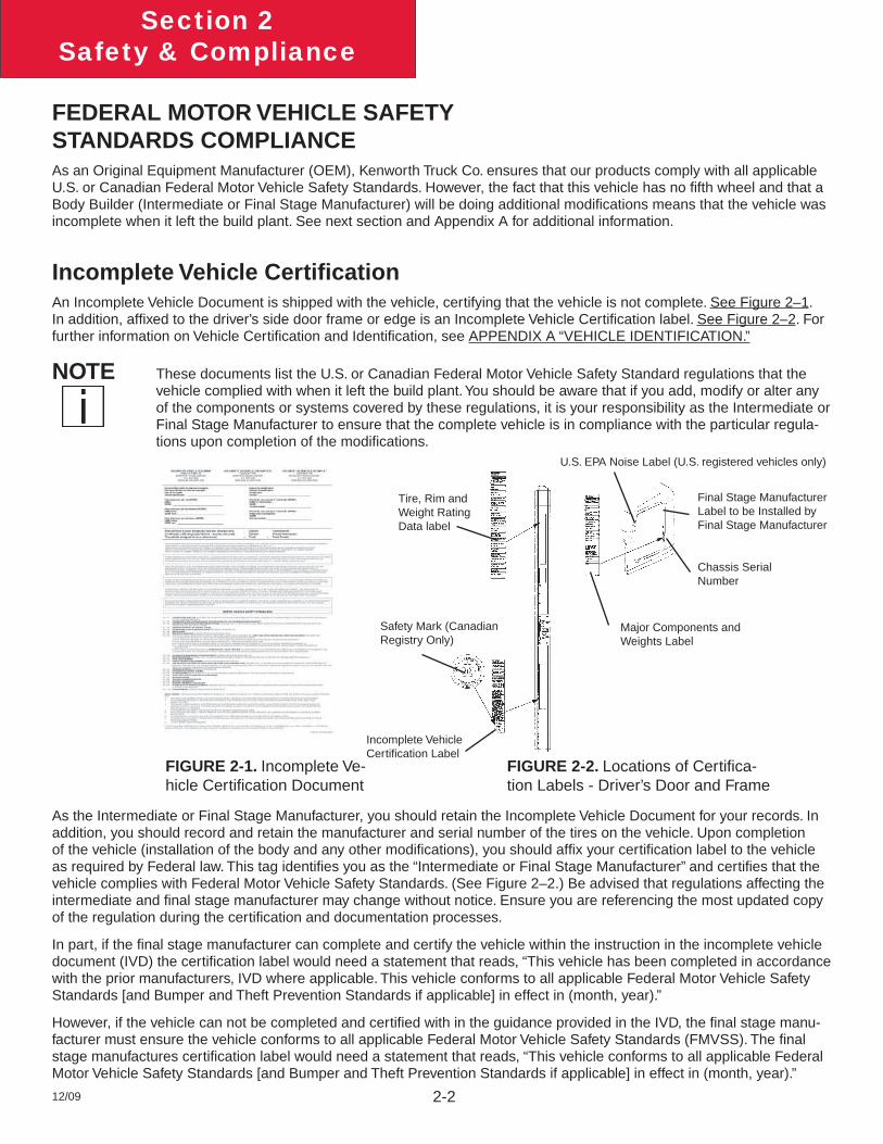
Incomplete Vehicle Certifi cationAn Incomplete Vehicle Document is shipped with the vehicle, certifying that the vehicle is not complete. See Figure 2–1. In addition, affi xed to the driver’s side door frame or edge is an Incomplete Vehicle Certifi cation label. See Figure 2–2. For further information on Vehicle Certifi cation and Identifi cation, see APPENDIX A “VEHICLE IDENTIFICATION.”
These documents list the U.S. or Canadian Federal Motor Vehicle Safety Standard regulations that the vehicle complied with when it left the build plant. You should be aware that if you add, modify or alter any of the components or systems covered by these regulations, it is your responsibility as the Intermediate or Final Stage Manufacturer to ensure that the complete vehicle is in compliance with the particular regula-tions upon completion of the modifi cations.
FIGURE 2-1. Incomplete Ve-hicle Certifi cation Document
FIGURE 2-2. Locations of Certifi ca-tion Labels - Driver’s Door and Frame
NOTE
U.S. EPA Noise Label (U.S. registered vehicles only)
Final Stage Manufacturer Label to be Installed by Final Stage Manufacturer
Chassis Serial Number
Major Components and Weights Label
Incomplete Vehicle Certifi cation Label
Safety Mark (Canadian Registry Only)
Tire, Rim and Weight Rating Data label
As the Intermediate or Final Stage Manufacturer, you should retain the Incomplete Vehicle Document for your records. In addition, you should record and retain the manufacturer and serial number of the tires on the vehicle. Upon completion of the vehicle (installation of the body and any other modifi cations), you should affi x your certifi cation label to the vehicle as required by Federal law. This tag identifi es you as the “Intermediate or Final Stage Manufacturer” and certifi es that the vehicle complies with Federal Motor Vehicle Safety Standards. (See Figure 2–2.) Be advised that regulations affecting the intermediate and fi nal stage manufacturer may change without notice. Ensure you are referencing the most updated copy of the regulation during the certifi cation and documentation processes.
In part, if the fi nal stage manufacturer can complete and certify the vehicle within the instruction in the incomplete vehicle document (IVD) the certifi cation label would need a statement that reads, “This vehicle has been completed in accordance with the prior manufacturers‚ IVD where applicable. This vehicle conforms to all applicable Federal Motor Vehicle Safety Standards [and Bumper and Theft Prevention Standards if applicable] in effect in (month, year).”
However, if the vehicle can not be completed and certifi ed with in the guidance provided in the IVD, the fi nal stage manu-facturer must ensure the vehicle conforms to all applicable Federal Motor Vehicle Safety Standards (FMVSS). The fi nal stage manufactures certifi cation label would need a statement that reads, “This vehicle conforms to all applicable Federal Motor Vehicle Safety Standards [and Bumper and Theft Prevention Standards if applicable] in effect in (month, year).”
Section 2Safety & Compliance
12/09 2-3
These statements are just part of the changes to the new certifi cation regulation. Please refer to the Feb 15, 2005 fi nal rule for all of the details related to this regulation. You can contact NTEA Technical Services Department at 1-800-441-NTEA for a copy of the fi nal rule (DocID 101760).
For Canadian fi nal stage manufacturers see:
http://www.gazette.gc.ca/archives/p2/2002/2002-02-13/html/sor-dors55-eng.html; andhttp://www.tc.gc.ca/acts-regulations/regulations/crc-c1038/menu.htm for the regulations.
Or contact:
Transport CanadaTower C, Place de Ville, 330 Sparks StreetOttawa, Ontario K1A 0N5(613) 990-2309TTY: 1-888-675-6863
Noise and Emissions Requirements
This truck may be equipped with specifi c emissions control components/systems* in order to meet applicable Federal and California noise and exhaust emissions requirements. Tampering with these emissions control components/systems* is against the rules that are established by the U.S Code of Federal Regulations, Environment Canada Regulations and California Air Resources Board (CARB). These emissions control components/systems* may only be replaced with original equipment parts.
Modifying (i.e. altering, substituting, relocating) any of the emissions control components/sys-tems defi ned above will affect the noise and emissions performance/certifi cation. If modifi cations are required, they must fi rst be approved by the engine manufacturer. Unapproved modifi cations could negatively effect emissions performance/certifi cation. There is no guarantee that proposed modifi cations will be approved.
Contact the engine manufacturer for any requirements and restrictions prior to any modifi cations.
For Cummins Contact: Please call 1-800-DIESELS or contact your local Cummins Distributor Reference • AEB 21.102.
It is possible to relocate the DEF tank, however the relocation requirements need to be followed. Any variance from the relocation requirements may cause the emissions control components/systems to operate improperly potentially resulting in engine de-rate. See page 4-3 for relocation requirements.
Some 2010 engine emissions certifi ed vehicles will be equipped with an On-Board Diagnostics (OBD) system. The OBD system is designed to detect malfunctions of any engine or vehicle component that may increase exhaust emissions or interfere with the proper performance of the OBD system itself.
The OBD system consists of computer program on one or more of the vehicle’s Electronic Control Units (ECUs). This program uses information from the control system and from additional sensors to detect malfunctions. When a malfunction is detected, information is stored in the ECU(s) for diagnostic purposes. A Malfunction Indicator Light (MIL) is illuminated in the dash to alert the driver of the need for service of an emission-related component or system.
NOTE
NOTE
Section 2Safety & Compliance
12/09 2-4
To ensure compliance to emissions regulations, the fi nal confi guration of certain features of the completed vehicle must meet specifi c requirements. This section describes requirements relevant for only the most common or critical modifi -cations done by body builders. For a complete description of acceptable modifi cations, see the application guidance available from the manufacturer of the engine installed in the chassis.
Fuel SystemThe following are highlights of some of the more common or critical aspects of this system.
The overall system restriction may not exceed the restriction limitations set forth by the engine manufacturer for both supply and return.
Ensure that fuel lines are not pinched or can potentially be damaged when installed between body and frame•
Fuel lines must be routed and secured without dips or sags•
There must be easy access to fi lter(s) and fi ll cap•
The tank vent may not obstructed•
Added accessories (heaters, generators) cannot introduce air into system•
Fuel tank must be located so that the full level is not above cylinder head•
“Ultra Low Sulfur Fuel Only” labels must be present on the dash and fuel fi ll •
Modifi cation of the pressure side secondary fi lter and plumbing is not allowed without engine manufacturer • approval
Body installation of fuel tank or routing of lines must not cause signifi cant increase in fuel temperature•
Fuel hoses shall meet or exceed OEM supplied hose material construction specifi cations•
Compressed Air SystemThe following are highlights of some of the more common or critical aspects of this system.
Air system modifi cation must meet applicable FMVSS regulations•
Compressed Air tank may not be modifi ed (exception – addition or removal of fi ttings or relocation of the tank) •
Added devices or bodywork may not interfere with or rub air lines•
Air supply to the engine doser may not be restricted or disconnected•
Air lines should be routed, protected from heat, and properly secured to prevent damage from other • components
Care should be taken so that air lines do not rub against other components•
Care should be taken to protect the air system from heat sources.•
Exhaust and Exhaust After-treatment SystemThe following are highlights of some of the more common or critical aspects of this system.
The following after-treatment and exhaust system components may not be modifi ed:•
DPF assembly• SCR Catalyst assembly• Exhaust pipes between the engine and after-treatment devices (DPF, SCR Catalyst) and between • after-treatment devices
Section 2Safety & Compliance
12/09 2-5
NO• x Sensor
The following modifi cations may only be done within the guidelines of the “DEF System Relocation Guide.”•
Modifi cations to Diesel Exhaust Fluid (DEF) throttle, suction, or pressure lines• Modifi cation or relocation of the DEF tank• Modifi cation of coolant lines to and from the DEF tank•
All DEF and coolant lines should be routed, protected, and properly secured to prevent damage during vehicle • operation or other components
If relocation of the DCU or ACM is necessary, use existing frame brackets and mount inside of frame fl anges • where necessary. Do not extend the harnesses
Exhaust pipes between the engine and after-treatment devices or between after-treatment devices may not be • modifi ed or replaced
The DPF, the SCR catalyst, or their mounting may not be modifi ed•
The NO• x sensor may not been relocated or altered in any way
Exhaust pipes used for tailpipes/stacks must be properly sized, and must prevent water from entering the • exhaust system
Ensure adequate clearance between the exhaust and body panels, hoses, and wire harnesses•
The body in the vicinity of the DPF must be able to withstand temperatures up to 400°C (750°F)•
Do not add thermal insulation to the external surface of the DPF•
The SCR water drain hole may not be blocked•
Allow adequate clearance (25mm (1 inch)) for servicing the DPF sensors, wiring, and clamped joints•
Drainage may not come in contact with the DPF, SCR catalyst, sensors or wiring•
Allow suffi cient clearance for removing sensors from DPF. Thermistors require four inches. Other sensors • require one inch
Wiring should be routed, protected from heat, and properly secured to prevent damage from • other components
The exhaust system from an auxiliary power unit (APU) must not be connected to any part of the vehicle • after-treatment system or vehicle tail pipe.
Cooling SystemThe following are highlights of some of the more common or critical aspects of this system.
Modifi cations to the design or locations of fi ll or vent lines, heater or defroster core, and surge tank are not • recommended
With the exception of post-thermostat installation, additional accessories plumbed into the engine cooling • system are not permitted, and may void vehicle warranty
Coolant level sensor tampering will void warranty•
When installing auxiliary equipment in front of the vehicle, or additional heat exchangers, ensure that • adequate air fl ow is available to the vehicle cooling system. Refer to engine manufacturer application guidelines for further detail
When installing FEPTO drivelines, the lower radiator anti-recirculation seal must be retained with FEPTO • driveline clearance modifi cation only
Section 2Safety & Compliance
12/09 2-6
Changes made to cooling fan circuit and controls are not allowed, with the exception of AC minimum fan on • time parameter
See owner’s manual for appropriate winter front usage•
Electrical SystemThe following are highlights of some of the more common or critical aspects of this system.
Electrical harnesses providing battery power and electronic control signals to engine and emissions control/• vehicle OBD components including datalinks may not be spliced. These emissions control/vehicle OBD components include the following:
throttle pedal• vehicle speed sensor• after-treatment wiring•
If the alternator or battery is substituted, it must meet the requirements of the engine manufacture’s guide-• lines. This includes alternator ground voltage drop and alternator ground cable effectiveness. See the engine manufacture’s guidelines for recommended test procedure. Additionally the maximum voltage differential and the peak-peak voltage differential between the engine ECM block ground stud and battery negative terminal may not exceed 500 mV under any combination of loads or operating conditions.
Installation of aftermarket transfer-cases must address the vehicle speed sensor position. The standard posi-• tion of the speed sensor is at the transmission tail shaft. When a transfer-case is added it is best to relocate the sensor to the axle side output shaft of the transfer-case. This is typically accomplished by adding a tone wheel into the driveline yoke assembly.
Wiring extensions for the after-treatment wiring are available for relocating the DEF tank from your dealer via • Paccar Parts. For relocation of DEF tank, refer to the after-treatment section of this manual.
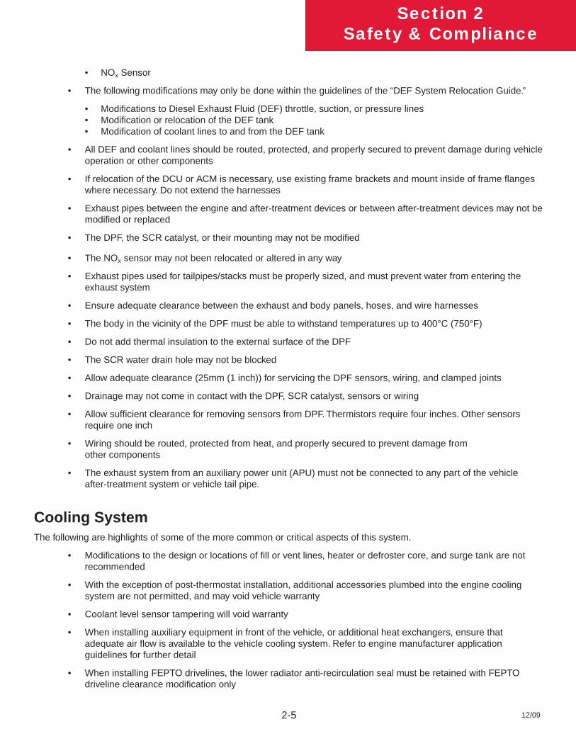
The emission system requires an accurate Outside Air Temperature (OAT) reading in order to properly run • its control algorithms. The OAT sensor is located in the driver’s side mirror assembly on Kenworth trucks and is shown in the fi gures below. If the body builder needs to modify the mirror assembly in any way, it is im-portant the OAT sensor stay positioned on the mirror assembly. Running the vehicle without the OAT sensor connected will cause the MIL lamp to illuminate. If needed, a replacement sensor can be ordered from your Kenworth dealer.
FIGURE 2-3: West Coast Mirror OAT sensor, located in overmold on mirror harness.
Section 2Safety & Compliance
12/09 2-7
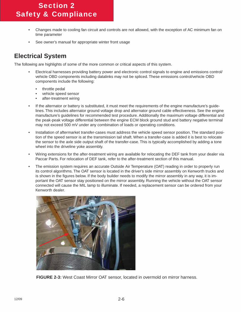
FIGURE 2-4: Aerodynamic Mirror OAT Sensor Location
Coolant Sensor considerations are given in the Cooling section above•
The OBD/Diagnostic connector port is located below the dash to the left of the steering wheel. This connector • or its location may not be changed.
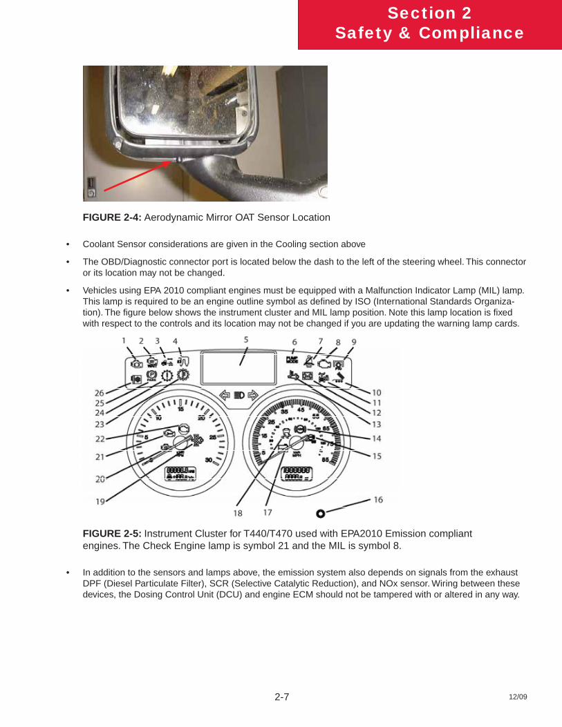
Vehicles using EPA 2010 compliant engines must be equipped with a Malfunction Indicator Lamp (MIL) lamp. • This lamp is required to be an engine outline symbol as defi ned by ISO (International Standards Organiza-tion). The fi gure below shows the instrument cluster and MIL lamp position. Note this lamp location is fi xed with respect to the controls and its location may not be changed if you are updating the warning lamp cards.
FIGURE 2-5: Instrument Cluster for T440/T470 used with EPA2010 Emission compliant engines. The Check Engine lamp is symbol 21 and the MIL is symbol 8.
In addition to the sensors and lamps above, the emission system also depends on signals from the exhaust • DPF (Diesel Particulate Filter), SCR (Selective Catalytic Reduction), and NOx sensor. Wiring between these devices, the Dosing Control Unit (DCU) and engine ECM should not be tampered with or altered in any way.

Section 2Safety & Compliance
12/09 2-8
Air Intake SystemThe following are highlights of some of the more common or critical aspects of this system.
The air intake screen may not be blocked, either fully or partially•
Modifi cation to the air intake system may not restrict airfl ow. For example, pipe diameter may not be reduced•
All sensors must be retained in existing locations•
To retain system seal, proper clamp torque must be used. Refer to service manual for proper clamp torque•
Charge Air Cooler SystemThe following are highlights of some of the more common or critical aspects of this system.
The Charge Air Cooler may not be modifi ed •
The installation of engine overspeed shutdown devices must not introduce restriction in the intake system•
All plumbing associated with the charge air cooler may not be modifi ed•
Section 3Dimensions
12/09 3-1
DIMENSIONSThis section has been designed to provide enough information to successfully layout chassis in the body planning process. Optional equipment may not be depicted. Please contact your local Kenworth dealer if more dimensional information is desired.
ABBREVIATIONSThroughout this section, and in other sections as well, abbreviations are used to describe certain characteristics on your vehicle. The chart below lists the abbreviated terms used.
TABLE 3-1. Abbreviations Used
AF AFTER FRAME – FRAME RAIL OVERHANG BEHIND REAR AXLE OR MEASURED FROM CENTERLINE OF TANDEM
CA BACK OF CAB TO CENTERLINE OF REAR AXLE OR CENTERLINE OF TANDEMS ON TANDEM SUSPENSION
EOF FRAME RAIL OVERHANG BEHIND REAR AXLE – MEASURED FROM THE CENTERLINE OF TANDEMS
FS FRONT SUSPENSION HEIGHT
RS REAR SUSPENSION HEIGHT
WB WHEELBASE
SOC SIDE OF CAB
BOC BACK OF CAB
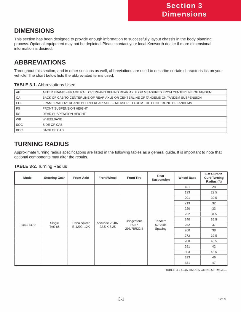
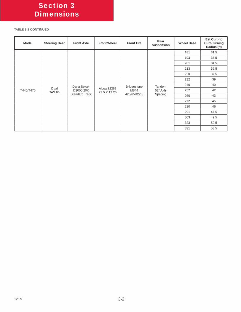
TURNING RADIUSApproximate turning radius specifi cations are listed in the following tables as a general guide. It is important to note that optional components may alter the results.
TABLE 3-2. Turning Radius
Model Steering Gear Front Axle Front Wheel Front TireRear
SuspensionWheel Base
Est Curb to Curb Turning
Radius (ft)
T440/T470Single TAS 65
Dana Spicer E-1202I 12K
Accuride 28487 22.5 X 8.25
Bridgestone R287
295/75R22.5
Tandem52” Axle Spacing
181 28
193 29.5
201 30.5
213 32
220 33
232 34.5
240 35.5
252 37
260 38
272 39.5
280 40.5
291 42
303 43.5
323 46
331 47
TABLE 3-2 CONTINUES ON NEXT PAGE…
Section 3Dimensions
12/09 3-2
Model Steering Gear Front Axle Front Wheel Front TireRear
SuspensionWheel Base
Est Curb to Curb Turning
Radius (ft)
T440/T470 Dual
TAS 65
Dana Spicer D2000 20K
Standard Track
Alcoa 82365 22.5 X 12.25
Bridgestone M844
425/65R22.5
Tandem52” Axle Spacing
181 31.5
193 33.5
201 34.5
213 36.5
220 37.5
232 39
240 40
252 42
260 43
272 45
280 46
291 47.5
303 49.5
323 52.5
331 53.5
TABLE 3-2 CONTINUED
Section 3Dimensions
12/09 3-3
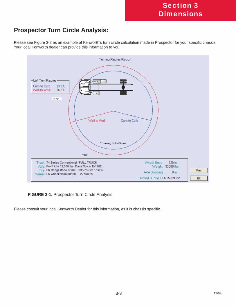
Prospector Turn Circle Analysis:
Please see Figure 3-2 as an example of Kenworth’s turn circle calculation made in Prospector for your specifi c chassis. Your local Kenworth dealer can provide this information to you.
FIGURE 3-1. Prospector Turn Circle Analysis
Please consult your local Kenworth Dealer for this information, as it is chassis specifi c.
T470
T470
Section 3Dimensions
12/09 3-4
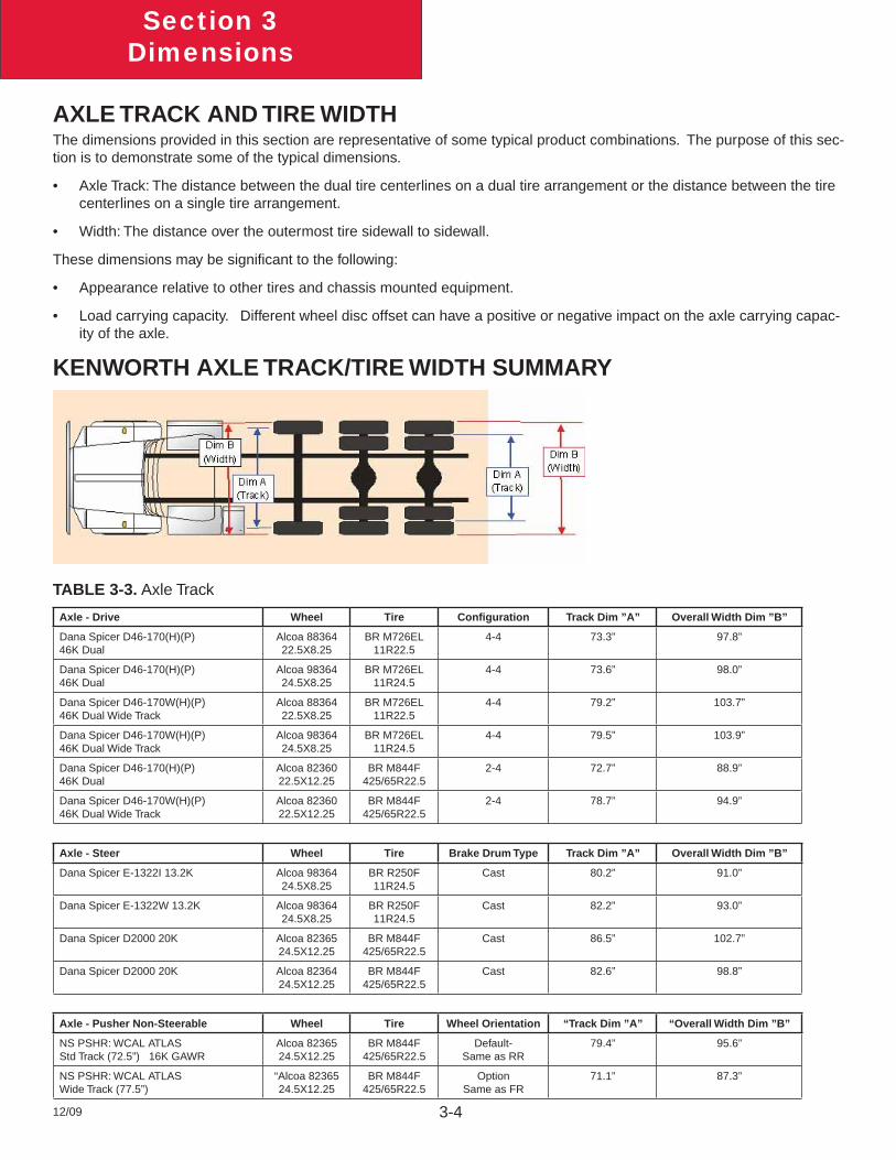
KENWORTH AXLE TRACK/TIRE WIDTH SUMMARY
Axle - Drive Wheel Tire Confi guration Track Dim ”A” Overall Width Dim ”B”
Dana Spicer D46-170(H)(P)46K Dual
Alcoa 8836422.5X8.25
BR M726EL11R22.5
4-4 73.3” 97.8”
Dana Spicer D46-170(H)(P)46K Dual
Alcoa 9836424.5X8.25
BR M726EL11R24.5
4-4 73.6” 98.0”
Dana Spicer D46-170W(H)(P)46K Dual Wide Track
Alcoa 8836422.5X8.25
BR M726EL11R22.5
4-4 79.2” 103.7”
Dana Spicer D46-170W(H)(P)46K Dual Wide Track
Alcoa 9836424.5X8.25
BR M726EL11R24.5
4-4 79.5” 103.9”
Dana Spicer D46-170(H)(P)46K Dual
Alcoa 8236022.5X12.25
BR M844F425/65R22.5
2-4 72.7” 88.9”
Dana Spicer D46-170W(H)(P)46K Dual Wide Track
Alcoa 8236022.5X12.25
BR M844F425/65R22.5
2-4 78.7” 94.9”
Axle - Steer Wheel Tire Brake Drum Type Track Dim ”A” Overall Width Dim ”B”
Dana Spicer E-1322I 13.2K Alcoa 9836424.5X8.25
BR R250F11R24.5
Cast 80.2” 91.0”
Dana Spicer E-1322W 13.2K Alcoa 9836424.5X8.25
BR R250F11R24.5
Cast 82.2” 93.0”
Dana Spicer D2000 20K Alcoa 8236524.5X12.25
BR M844F425/65R22.5
Cast 86.5” 102.7”
Dana Spicer D2000 20K Alcoa 8236424.5X12.25
BR M844F425/65R22.5
Cast 82.6” 98.8”
Axle - Pusher Non-Steerable Wheel Tire Wheel Orientation “Track Dim ”A” “Overall Width Dim ”B”
NS PSHR: WCAL ATLASStd Track (72.5”) 16K GAWR
Alcoa 8236524.5X12.25
BR M844F425/65R22.5
Default-Same as RR
79.4” 95.6”
NS PSHR: WCAL ATLASWide Track (77.5”)
“Alcoa 8236524.5X12.25
BR M844F425/65R22.5
OptionSame as FR
71.1” 87.3”
TABLE 3-3. Axle Track
AXLE TRACK AND TIRE WIDTHThe dimensions provided in this section are representative of some typical product combinations. The purpose of this sec-tion is to demonstrate some of the typical dimensions.
Axle Track: The distance between the dual tire centerlines on a dual tire arrangement or the distance between the tire • centerlines on a single tire arrangement.
Width: The distance over the outermost tire sidewall to sidewall.•
These dimensions may be signifi cant to the following:
Appearance relative to other tires and chassis mounted equipment.•
Load carrying capacity. Different wheel disc offset can have a positive or negative impact on the axle carrying capac-• ity of the axle.
Section 3Dimensions
12/09 3-5
OVERALL DIMENSIONSThis section includes drawings and charts. The Extended Day Cab is also included.
On the pages that follow, detail drawings show particular views of each vehicle, all dimensions are in inches (in). They illustrate important measurements critical to designing bodies of all types. See the “Contents” at the beginning of the manual to locate the drawing that you need.
Note: To determine overall height please locate the chart Table 3-4 on page 3-8 and 3-9 and add that value to the height. All heights are given from the bottom of the frame rail.
Kenworth also offers .dxf fi les and frame layouts of ordered chassis four weeks prior to build. Please speak with your salesman to request this feature when specifying your chassis.
Section 3Dimensions
12/09 3-6
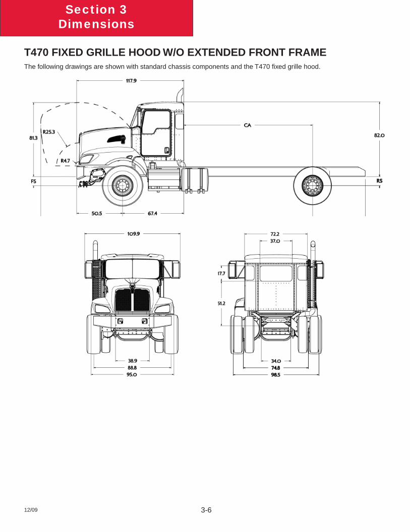
T470 FIXED GRILLE HOOD W/O EXTENDED FRONT FRAMEThe following drawings are shown with standard chassis components and the T470 fi xed grille hood.
Section 3Dimensions
12/09 3-7
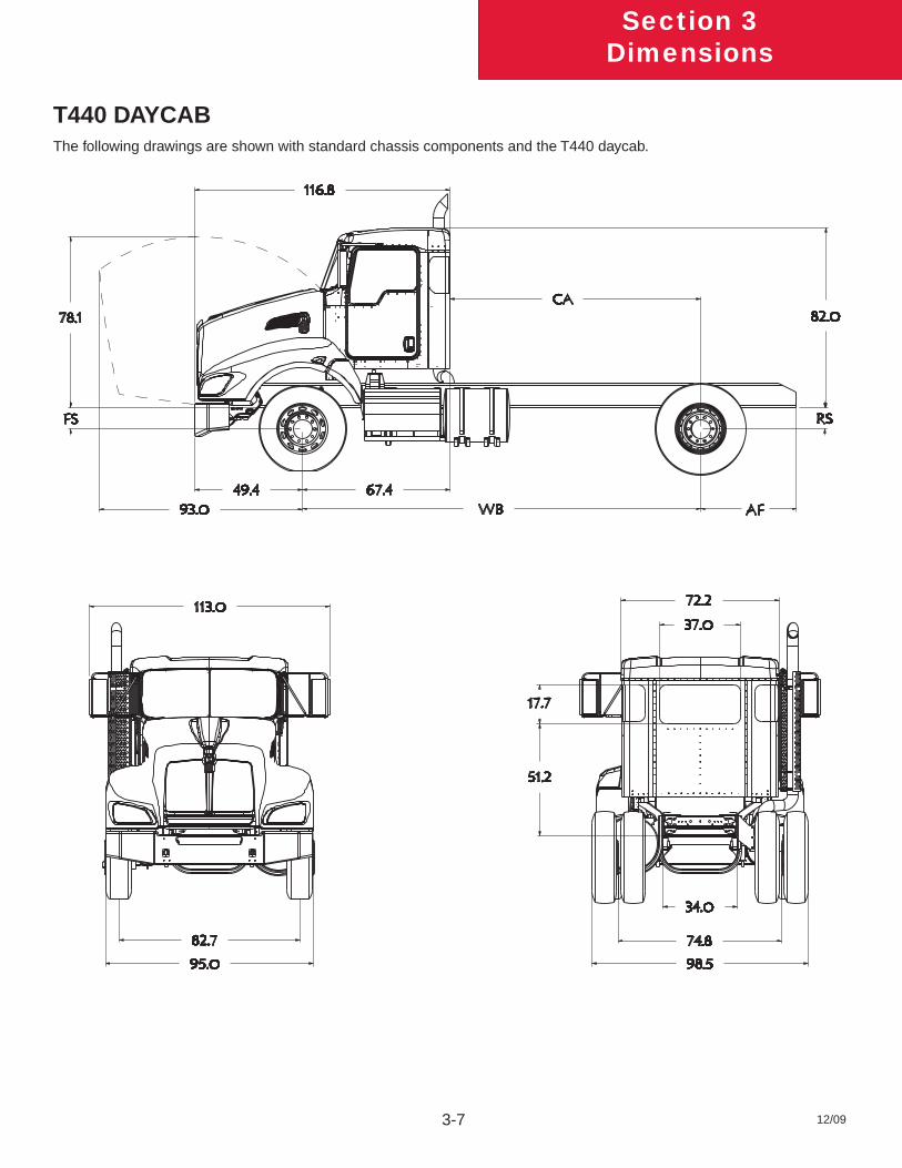
T440 DAYCABThe following drawings are shown with standard chassis components and the T440 daycab.
Section 3Dimensions
12/09 3-8
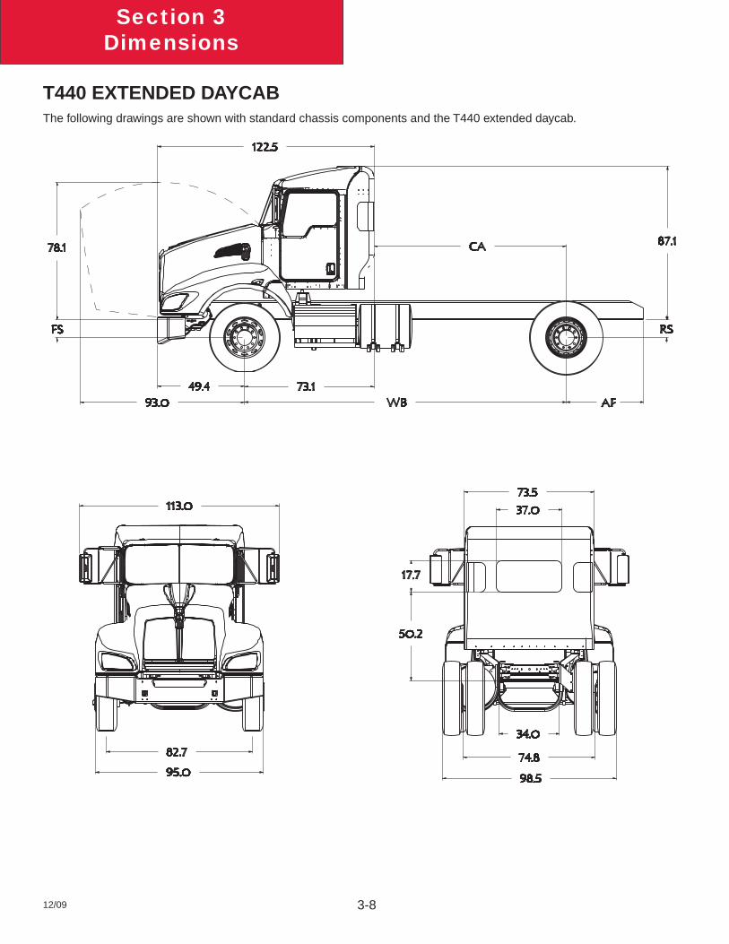
T440 EXTENDED DAYCABThe following drawings are shown with standard chassis components and the T440 extended daycab.
Section 3Dimensions
12/09 3-9
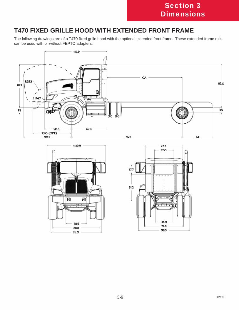
T470 FIXED GRILLE HOOD WITH EXTENDED FRONT FRAMEThe following drawings are of a T470 fi xed grille hood with the optional extended front frame. These extended frame rails can be used with or without FEPTO adapters.
Section 3Dimensions
12/09 3-10
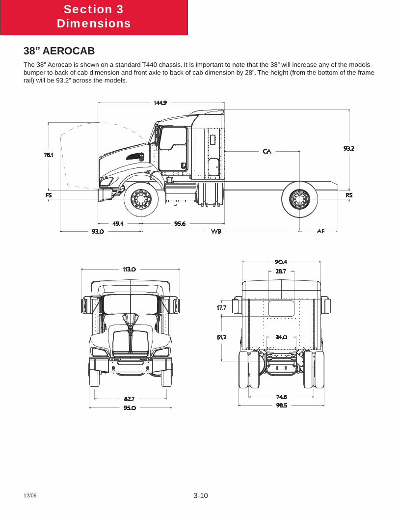
38” AEROCABThe 38” Aerocab is shown on a standard T440 chassis. It is important to note that the 38” will increase any of the models bumper to back of cab dimension and front axle to back of cab dimension by 28”. The height (from the bottom of the frame rail) will be 93.2” across the models.
Section 3Dimensions
12/09 3-11
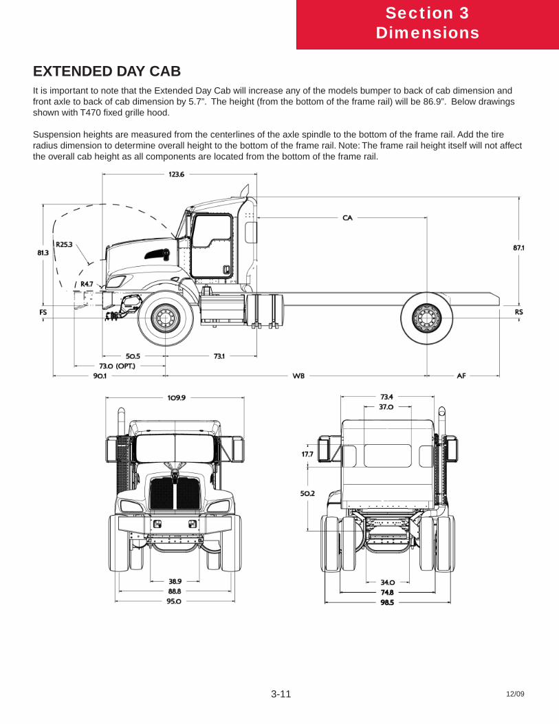
EXTENDED DAY CABIt is important to note that the Extended Day Cab will increase any of the models bumper to back of cab dimension and front axle to back of cab dimension by 5.7”. The height (from the bottom of the frame rail) will be 86.9”. Below drawings shown with T470 fi xed grille hood.
Suspension heights are measured from the centerlines of the axle spindle to the bottom of the frame rail. Add the tire radius dimension to determine overall height to the bottom of the frame rail. Note: The frame rail height itself will not affect the overall cab height as all components are located from the bottom of the frame rail.
Section 3Dimensions
12/09 3-12
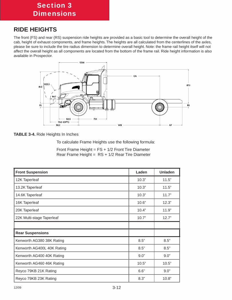
RIDE HEIGHTSThe front (FS) and rear (RS) suspension ride heights are provided as a basic tool to determine the overall height of the cab, height of exhaust components, and frame heights. The heights are all calculated from the centerlines of the axles, please be sure to include the tire radius dimension to determine overall height. Note: the frame rail height itself will not affect the overall height as all components are located from the bottom of the frame rail. Ride height information is also available in Prospector.
TABLE 3-4. Ride Heights In Inches
To calculate Frame Heights use the following formula:
Front Frame Height = FS + 1/2 Front Tire Diameter Rear Frame Height = RS + 1/2 Rear Tire Diameter
Front Suspension Laden Unladen
12K Taperleaf 10.3” 11.5”
13.2K Taperleaf 10.3” 11.5”
14.6K Taperleaf 10.3” 11.7”
16K Taperleaf 10.6” 12.3”
20K Taperleaf 10.4” 11.9”
22K Multi-stage Taperleaf 10.7” 12.7”
Rear Suspensions
Kenworth AG380 38K Rating 8.5” 8.5”
Kenworth AG400L 40K Rating 8.5” 8.5”
Kenworth AG400 40K Rating 9.0” 9.0”
Kenworth AG460 46K Rating 10.5” 10.5”
Reyco 79KB 21K Rating 6.6” 9.0”
Reyco 79KB 23K Rating 8.3” 10.8”
Section 3Dimensions
12/09 3-13
Reyco 79KB 26K Rating 8.2” 11.3”
Reyco 102 38K Rating 9.2” 10.8”
Reyco 102 40 K Rating 9.2” 10.8”
Chalmers 854-40-L-HS 40K Rating 9.6” 11.0”
Chalmers 854-40-H-HS 40K Rating 10.9” 12.4”
Chalmers 854-46-L 46K Rating 8.9” 11.3”
Chalmers 854-46-L-HS 46K Rating 9.6” 11.3”
Chalmers 854-46-H 46K Rating 10.1” 12.4”
Chalmers 854-46-H-HS 46K Rating 10.9” 12.5”
Chalmers 860-46-H-HS 46K Rating 10.9” 12.5”
Chalmers 872-46-H-HS 46K Rating 11.0” 12.5”
Hendrickson HAS 230 23K Rating 10.0” 10.0”
Hend HMX460 16.5” Saddle 46K Rating 9.5” 10.6”
Hend HMX460 17.5” Saddle 46K Rating 10.5” 11.6”
Hend HMX460 18.5” Saddle 46K Rating 11.5” 12.6”
Hendrickson Primaax 46K Rating 10.0” 10.0”
Hendrickson RT403 40K Rating 9.7” 10.7”
Hendrickson RT463 6.0” Saddle 46K Rating 10.0” 11.1”
Hendrickson RT463 7.19 Saddle 46K Rating 11.2” 12.5”
Hendrickson RT463 7.94 Saddle 46K Rating 11.9” 13.3”
Neway AD123 23K Rating 10.0” 10.0”
Neway AD126 26K Rating 10.0” 10.0”
Neway AD246 46K Rating 10.0” 10.0”
Section 3Dimensions
12/09 3-14
REAR SUSPENSION LAYOUTSThe rear suspension layouts are provided as a tool to help layout bodies prior to arrival. Be sure to check the axle spacing that is shown, as alternate spacings may exist and could change some of the dimensions. The dimensions shown below are the most typical installations, in special cases some hole locations will move. If you are planning on using the holes shown for your body installation, please confi rm with your local KW dealer that the drawing below will be the installation used on your specifi c truck. Ensure that proper torque is used to reinstall any suspension components. See Tables 5-1 and 5-2 on page 5-7.
It would be a good idea in this case to order the frame layout of your chassis along with your truck order. This can be done on any Kenworth truck, and will be provided 4 weeks ahead of the build schedule.
If there are hole locations that are not detailed please work with your local Kenworth Dealer to request that information.
Additionally optional axle spacings are shown in the charts, if you would like details on the frame drilling with optional spacings, please contact your local Kenworth dealer.
Section 3Dimensions
12/09 3-15
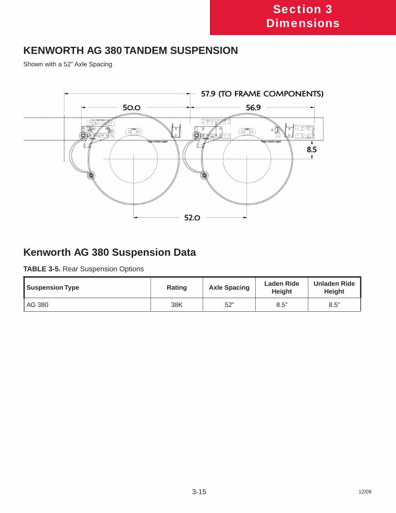
KENWORTH AG 380 TANDEM SUSPENSIONShown with a 52” Axle Spacing
Kenworth AG 380 Suspension Data
TABLE 3-5. Rear Suspension Options
Suspension Type Rating Axle SpacingLaden Ride
HeightUnladen Ride
Height
AG 380 38K 52” 8.5” 8.5”

Section 3Dimensions
12/09 3-16
KENWORTH AG 400/460 TANDEM SUSPENSIONShown with a 52” Axle Spacing
Optional Kenworth Tandem Suspensions
TABLE 3-6. Rear Suspension Options
Suspension Type Rating Axle SpacingLaden Ride
HeightUnladen Ride
Height
Kenworth AG 400 40K 52” 9” 9”
Kenworth AG 400 40K 54” 9” 9’
Kenworth AG 460 46K 54” 10.5” 10.5”
Section 3Dimensions
12/09 3-17
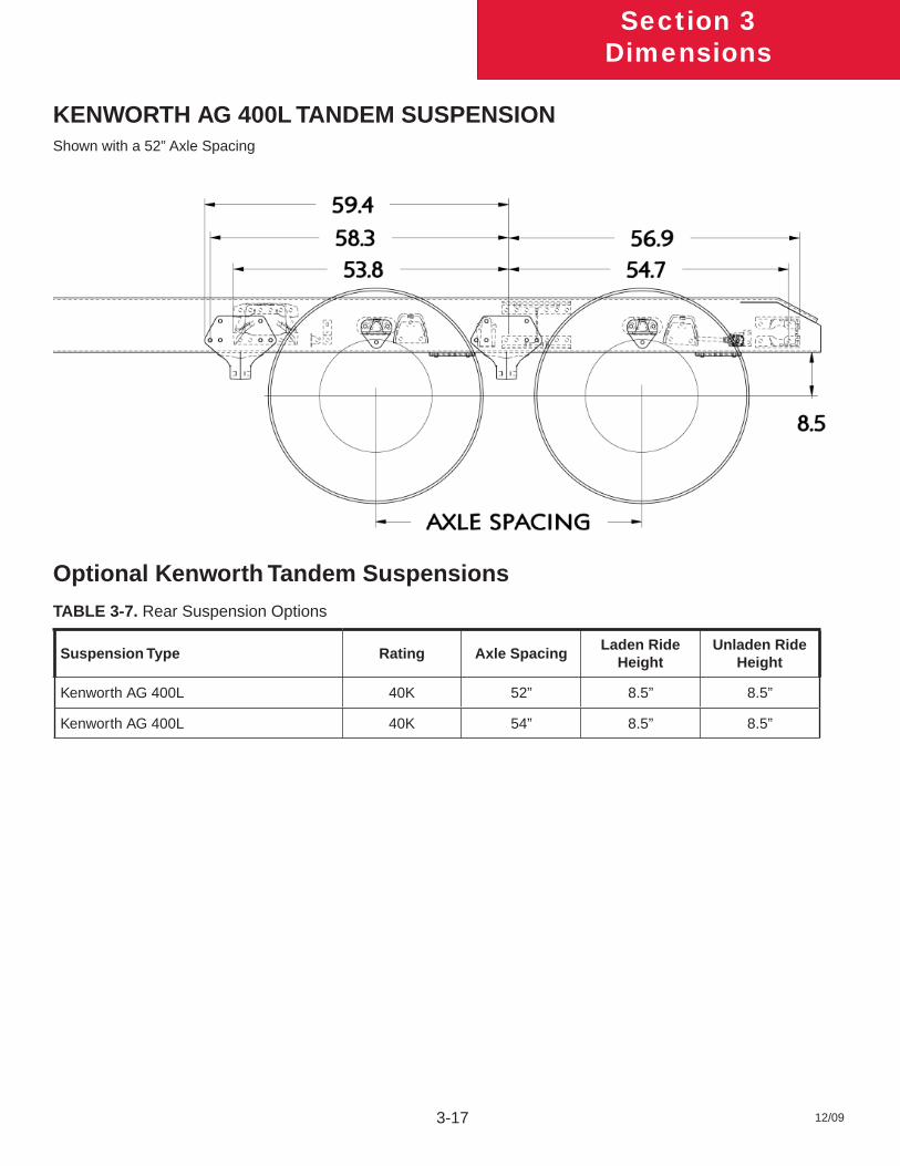
KENWORTH AG 400L TANDEM SUSPENSIONShown with a 52” Axle Spacing
Optional Kenworth Tandem Suspensions
TABLE 3-7. Rear Suspension Options
Suspension Type Rating Axle SpacingLaden Ride
HeightUnladen Ride
Height
Kenworth AG 400L 40K 52” 8.5” 8.5”
Kenworth AG 400L 40K 54” 8.5” 8.5”
Section 3Dimensions
12/09 3-18
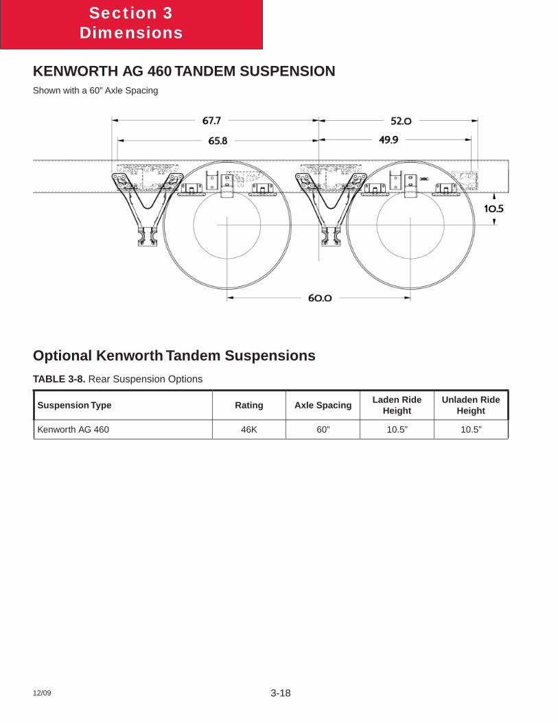
KENWORTH AG 460 TANDEM SUSPENSIONShown with a 60” Axle Spacing
Optional Kenworth Tandem Suspensions
TABLE 3-8. Rear Suspension Options
Suspension Type Rating Axle SpacingLaden Ride
HeightUnladen Ride
Height
Kenworth AG 460 46K 60” 10.5” 10.5”
Section 3Dimensions
12/09 3-19
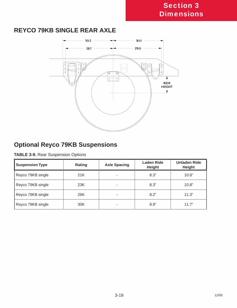
REYCO 79KB SINGLE REAR AXLE
Optional Reyco 79KB Suspensions
TABLE 3-9. Rear Suspension Options
Suspension Type Rating Axle SpacingLaden Ride
HeightUnladen Ride
Height
Reyco 79KB single 21K - 8.3” 10.8”
Reyco 79KB single 23K - 8.3” 10.8”
Reyco 79KB single 26K - 8.2” 11.3”
Reyco 79KB single 30K - 8.9” 11.7”
Section 3Dimensions
12/09 3-20
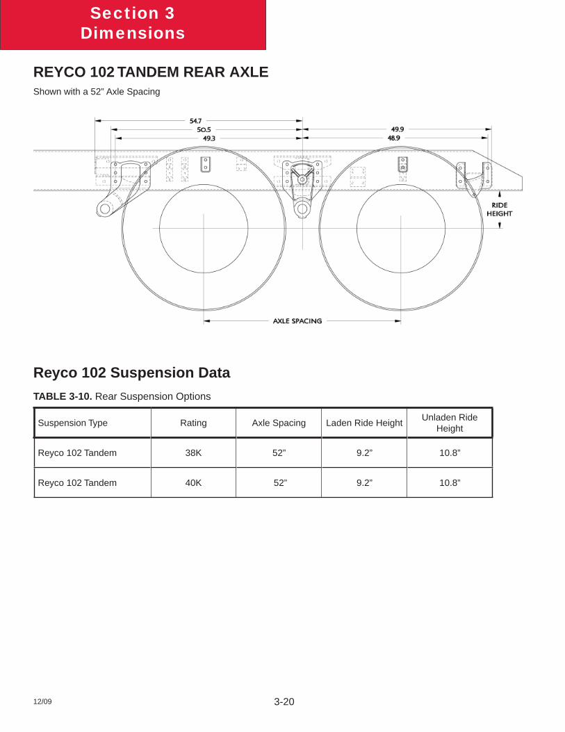
REYCO 102 TANDEM REAR AXLEShown with a 52” Axle Spacing
Reyco 102 Suspension Data
TABLE 3-10. Rear Suspension Options
Suspension Type Rating Axle Spacing Laden Ride HeightUnladen Ride
Height
Reyco 102 Tandem 38K 52” 9.2” 10.8”
Reyco 102 Tandem 40K 52” 9.2” 10.8”
Section 3Dimensions
12/09 3-21
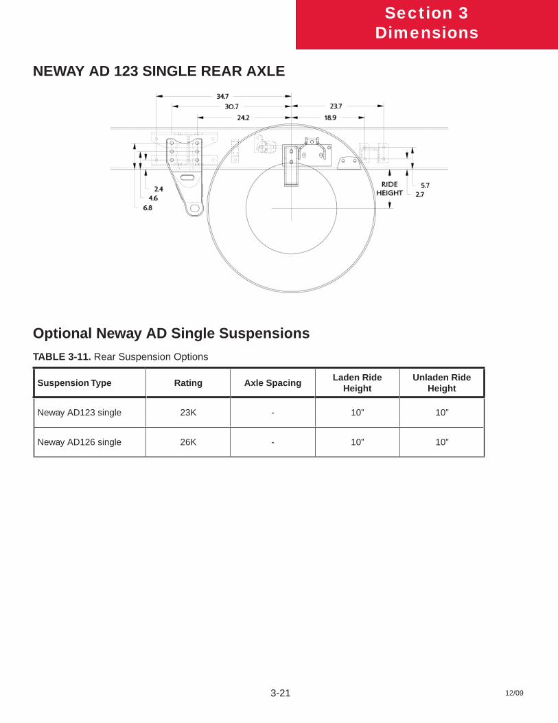
NEWAY AD 123 SINGLE REAR AXLE
Optional Neway AD Single Suspensions
TABLE 3-11. Rear Suspension Options
Suspension Type Rating Axle SpacingLaden Ride
HeightUnladen Ride
Height
Neway AD123 single 23K - 10” 10”
Neway AD126 single 26K - 10” 10”
Section 3Dimensions
12/09 3-22
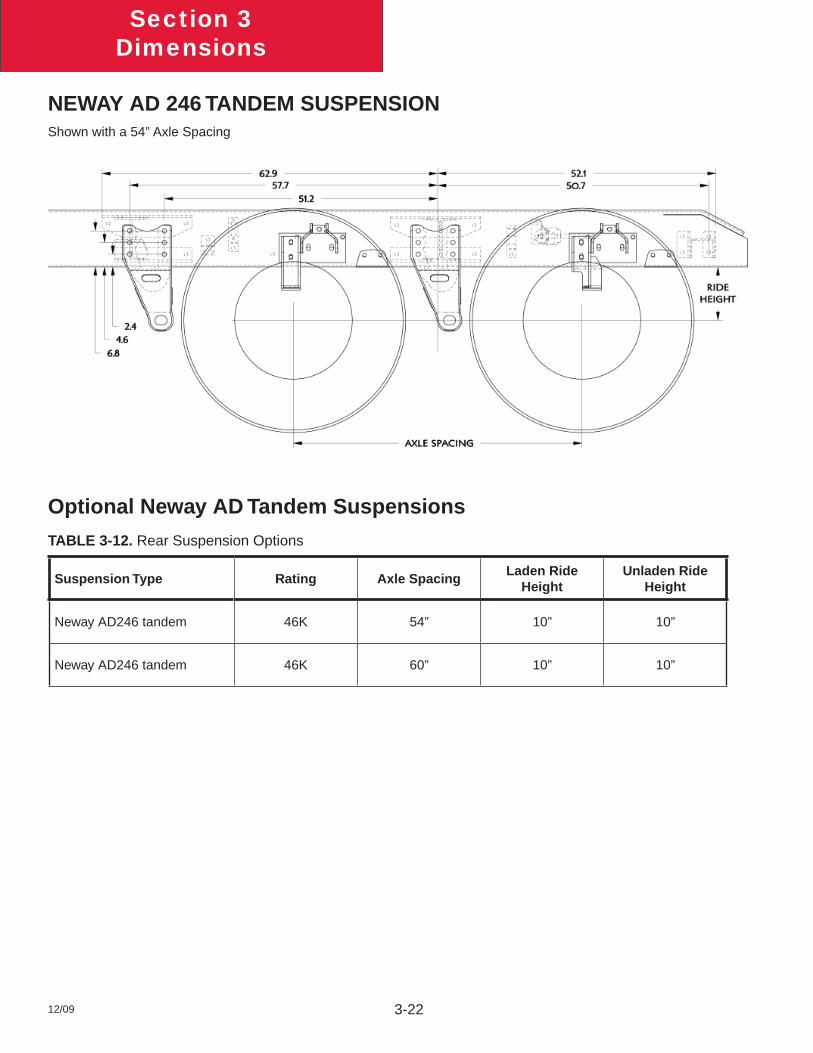
NEWAY AD 246 TANDEM SUSPENSIONShown with a 54” Axle Spacing
Optional Neway AD Tandem Suspensions
TABLE 3-12. Rear Suspension Options
Suspension Type Rating Axle SpacingLaden Ride
HeightUnladen Ride
Height
Neway AD246 tandem 46K 54” 10” 10”
Neway AD246 tandem 46K 60” 10” 10”
Section 3Dimensions
12/09 3-23
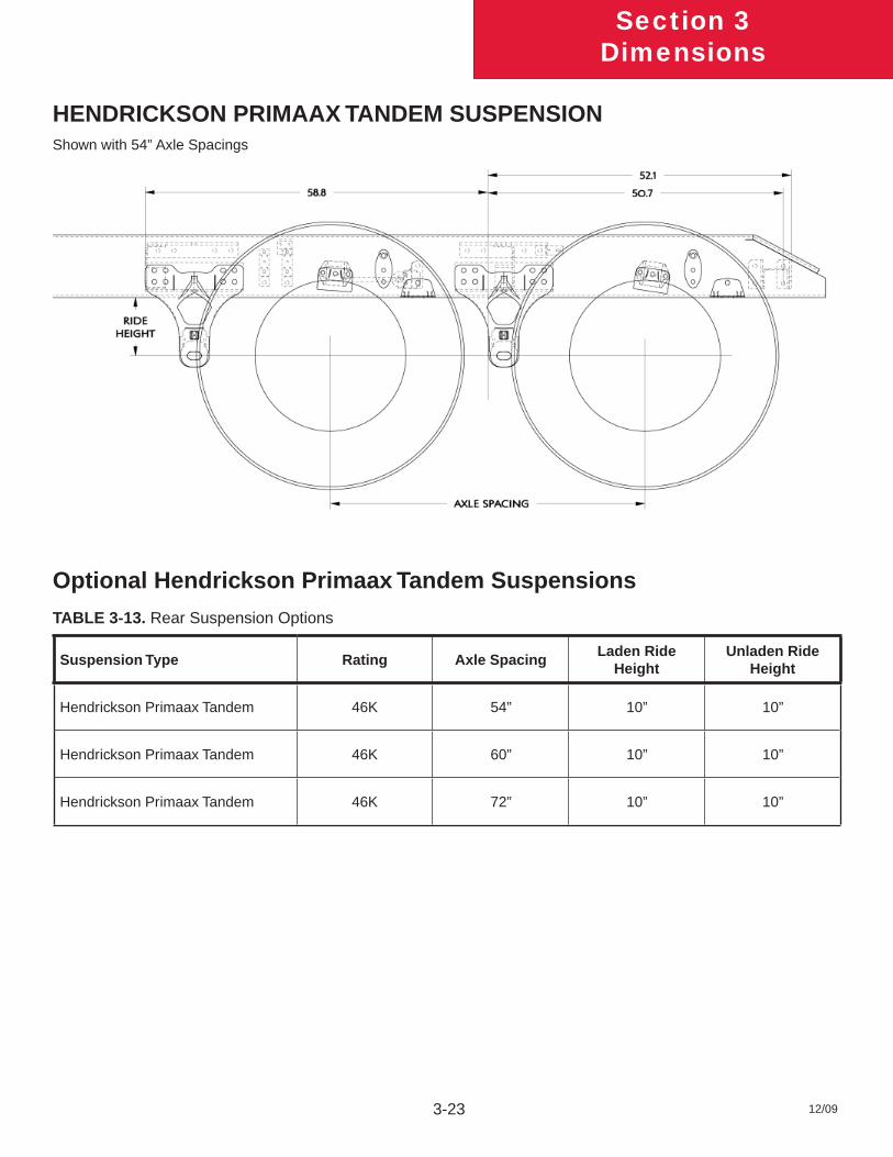
HENDRICKSON PRIMAAX TANDEM SUSPENSIONShown with 54” Axle Spacings
Optional Hendrickson Primaax Tandem Suspensions
TABLE 3-13. Rear Suspension Options
Suspension Type Rating Axle SpacingLaden Ride
HeightUnladen Ride
Height
Hendrickson Primaax Tandem 46K 54” 10” 10”
Hendrickson Primaax Tandem 46K 60” 10” 10”
Hendrickson Primaax Tandem 46K 72” 10” 10”
Section 3Dimensions
12/09 3-24
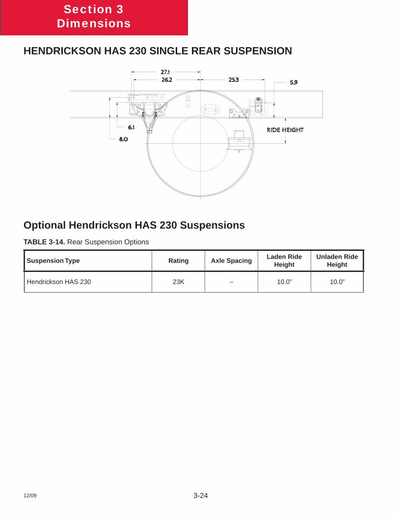
HENDRICKSON HAS 230 SINGLE REAR SUSPENSION
Optional Hendrickson HAS 230 Suspensions
TABLE 3-14. Rear Suspension Options
Suspension Type Rating Axle SpacingLaden Ride
HeightUnladen Ride
Height
Hendrickson HAS 230 23K – 10.0” 10.0”
Section 3Dimensions
12/09 3-25
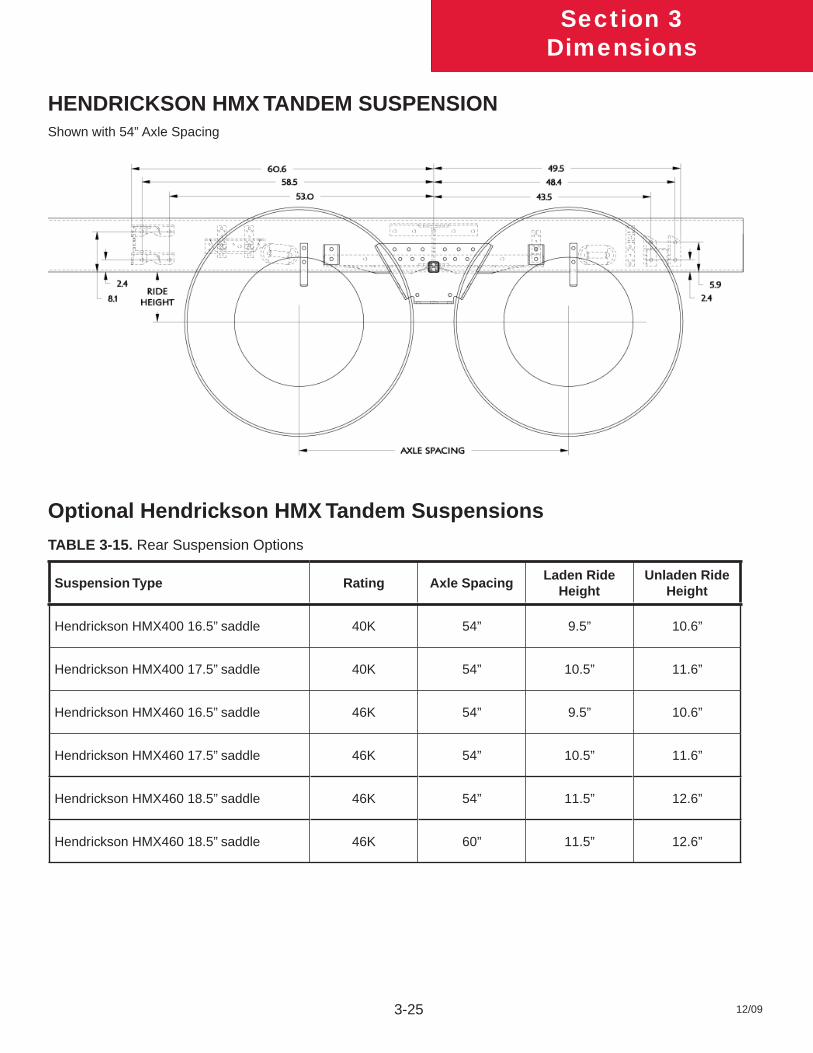
HENDRICKSON HMX TANDEM SUSPENSIONShown with 54” Axle Spacing
Optional Hendrickson HMX Tandem Suspensions
TABLE 3-15. Rear Suspension Options
Suspension Type Rating Axle SpacingLaden Ride
HeightUnladen Ride
Height
Hendrickson HMX400 16.5” saddle 40K 54” 9.5” 10.6”
Hendrickson HMX400 17.5” saddle 40K 54” 10.5” 11.6”
Hendrickson HMX460 16.5” saddle 46K 54” 9.5” 10.6”
Hendrickson HMX460 17.5” saddle 46K 54” 10.5” 11.6”
Hendrickson HMX460 18.5” saddle 46K 54” 11.5” 12.6”
Hendrickson HMX460 18.5” saddle 46K 60” 11.5” 12.6”
Section 3Dimensions
12/09 3-26
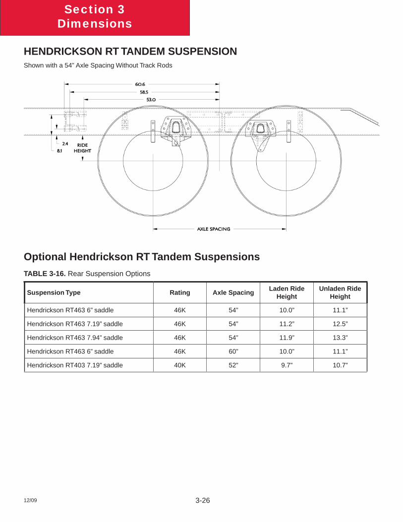
HENDRICKSON RT TANDEM SUSPENSIONShown with a 54” Axle Spacing Without Track Rods
Optional Hendrickson RT Tandem Suspensions
TABLE 3-16. Rear Suspension Options
Suspension Type Rating Axle SpacingLaden Ride
HeightUnladen Ride
Height
Hendrickson RT463 6” saddle 46K 54” 10.0” 11.1”
Hendrickson RT463 7.19” saddle 46K 54” 11.2” 12.5”
Hendrickson RT463 7.94” saddle 46K 54” 11.9” 13.3”
Hendrickson RT463 6” saddle 46K 60” 10.0” 11.1”
Hendrickson RT403 7.19” saddle 40K 52” 9.7” 10.7”
Section 3Dimensions
12/09 3-27
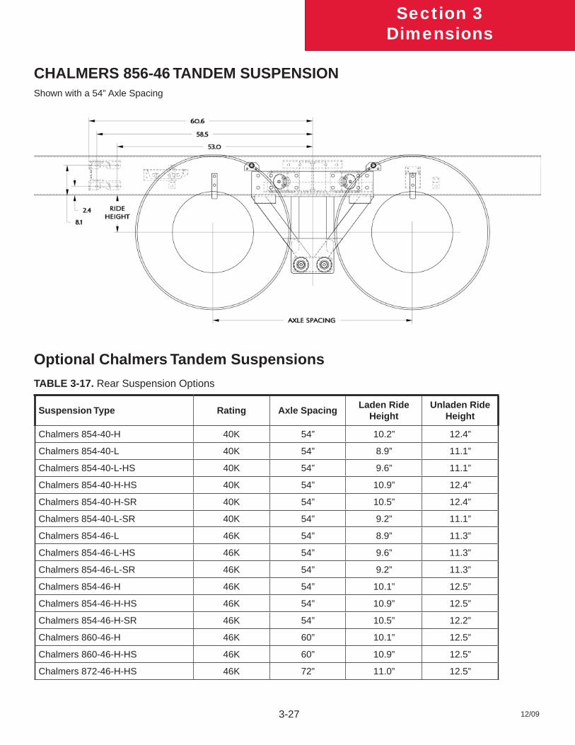
CHALMERS 856-46 TANDEM SUSPENSIONShown with a 54” Axle Spacing
Optional Chalmers Tandem Suspensions
TABLE 3-17. Rear Suspension Options
Suspension Type Rating Axle SpacingLaden Ride
HeightUnladen Ride
Height
Chalmers 854-40-H 40K 54” 10.2” 12.4”
Chalmers 854-40-L 40K 54” 8.9” 11.1”
Chalmers 854-40-L-HS 40K 54” 9.6” 11.1”
Chalmers 854-40-H-HS 40K 54” 10.9” 12.4”
Chalmers 854-40-H-SR 40K 54” 10.5” 12.4”
Chalmers 854-40-L-SR 40K 54” 9.2” 11.1”
Chalmers 854-46-L 46K 54” 8.9” 11.3”
Chalmers 854-46-L-HS 46K 54” 9.6” 11.3”
Chalmers 854-46-L-SR 46K 54” 9.2” 11.3”
Chalmers 854-46-H 46K 54” 10.1” 12.5”
Chalmers 854-46-H-HS 46K 54” 10.9” 12.5”
Chalmers 854-46-H-SR 46K 54” 10.5” 12.2”
Chalmers 860-46-H 46K 60” 10.1” 12.5”
Chalmers 860-46-H-HS 46K 60” 10.9” 12.5”
Chalmers 872-46-H-HS 46K 72” 11.0” 12.5”
Section 3Dimensions
12/09 3-28
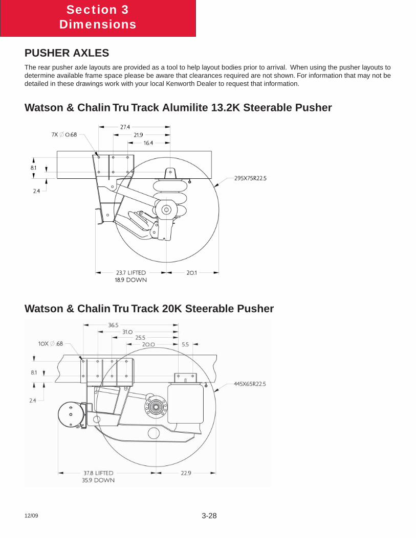
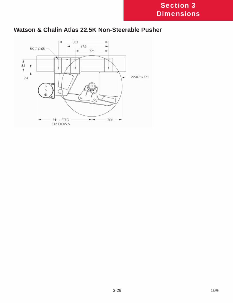
PUSHER AXLESThe rear pusher axle layouts are provided as a tool to help layout bodies prior to arrival. When using the pusher layouts to determine available frame space please be aware that clearances required are not shown. For information that may not be detailed in these drawings work with your local Kenworth Dealer to request that information.
Watson & Chalin Tru Track Alumilite 13.2K Steerable Pusher
Watson & Chalin Tru Track 20K Steerable Pusher
Section 3Dimensions
12/09 3-29
Watson & Chalin Atlas 22.5K Non-Steerable Pusher
Section 3Dimensions
12/09 3-30
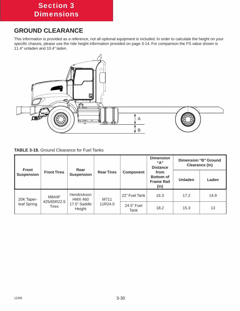
GROUND CLEARANCEThis information is provided as a reference, not all optional equipment is included. In order to calculate the height on your specifi c chassis, please use the ride height information provided on page 3-14. For comparison the FS value shown is 11.4” unladen and 10.4” laden.
TABLE 3-18. Ground Clearance for Fuel Tanks
Front Suspension
Front TiresRear
SuspensionRear Tires Component
Dimension “A”
Distance from
Bottom of Frame Rail
(in)
Dimension “B” Ground Clearance (in)
Unladen Laden
20K Taper-leaf Spring
M844F 425/65R22.5
Tires
Hendrickson HMX 460
17.5” Saddle Height
M711 11R24.5
22” Fuel Tank 16.3 17.2 14.9
24.5” Fuel Tank
18.2 15.3 13
A
B
Section 3Dimensions
12/09 3-31
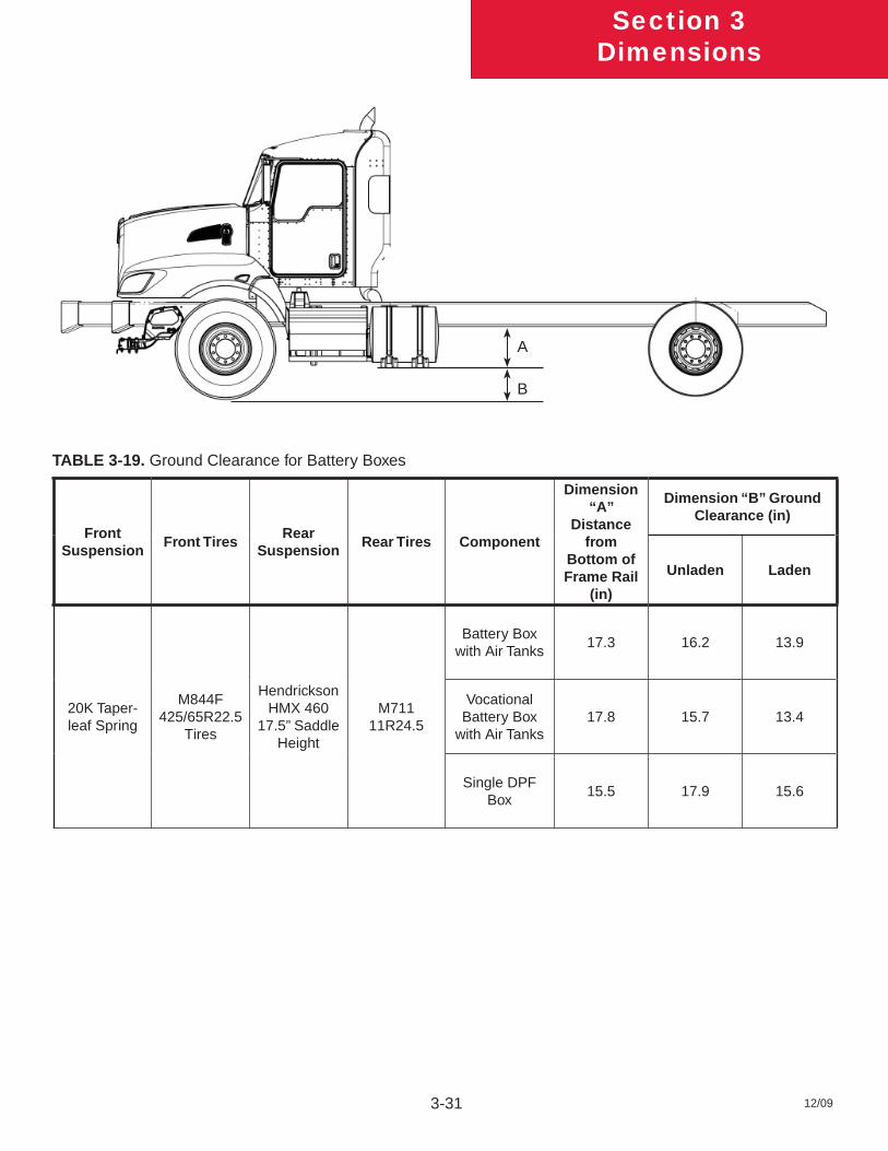
TABLE 3-19. Ground Clearance for Battery Boxes
Front Suspension
Front TiresRear
SuspensionRear Tires Component
Dimension “A”
Distance from
Bottom of Frame Rail
(in)
Dimension “B” Ground Clearance (in)
Unladen Laden
20K Taper-leaf Spring
M844F 425/65R22.5
Tires
Hendrickson HMX 460
17.5” Saddle Height
M711 11R24.5
Battery Box with Air Tanks
17.3 16.2 13.9
Vocational Battery Box
with Air Tanks17.8 15.7 13.4
Single DPF Box
15.5 17.9 15.6
A
B
Section 3Dimensions
12/09 3-32
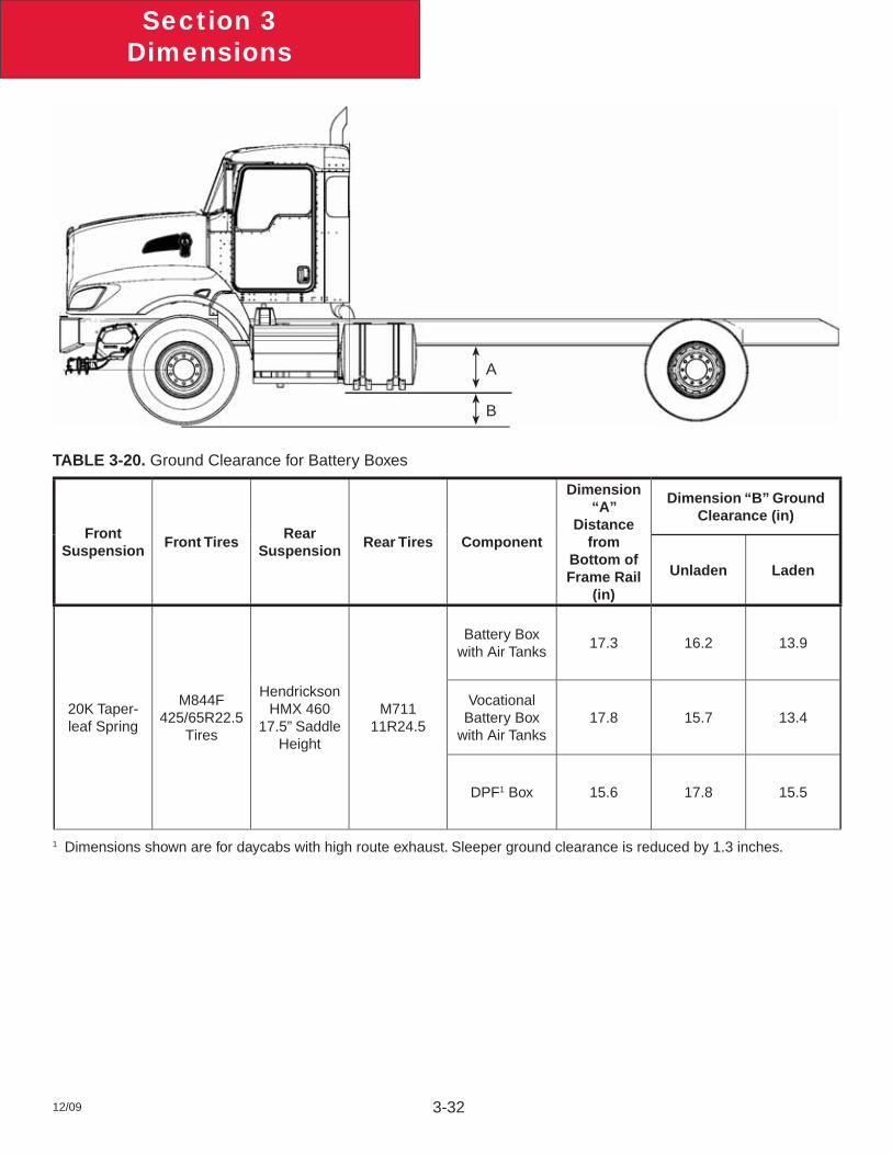
TABLE 3-20. Ground Clearance for Battery Boxes
Front Suspension
Front TiresRear
SuspensionRear Tires Component
Dimension “A”
Distance from
Bottom of Frame Rail
(in)
Dimension “B” Ground Clearance (in)
Unladen Laden
20K Taper-leaf Spring
M844F 425/65R22.5
Tires
Hendrickson HMX 460
17.5” Saddle Height
M711 11R24.5
Battery Box with Air Tanks
17.3 16.2 13.9
Vocational Battery Box
with Air Tanks17.8 15.7 13.4
DPF1 Box 15.6 17.8 15.5
1 Dimensions shown are for daycabs with high route exhaust. Sleeper ground clearance is reduced by 1.3 inches.
A
B
Section 3Dimensions
12/09 3-33
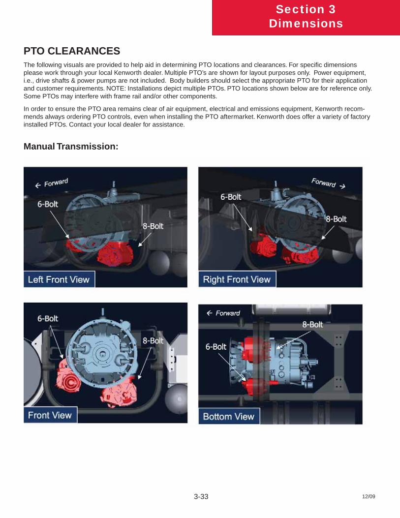
PTO CLEARANCESThe following visuals are provided to help aid in determining PTO locations and clearances. For specifi c dimensions please work through your local Kenworth dealer. Multiple PTO’s are shown for layout purposes only. Power equipment, i.e., drive shafts & power pumps are not included. Body builders should select the appropriate PTO for their application and customer requirements. NOTE: Installations depict multiple PTOs. PTO locations shown below are for reference only. Some PTOs may interfere with frame rail and/or other components.
In order to ensure the PTO area remains clear of air equipment, electrical and emissions equipment, Kenworth recom-mends always ordering PTO controls, even when installing the PTO aftermarket. Kenworth does offer a variety of factory installed PTOs. Contact your local dealer for assistance.
Manual Transmission:
Section 3Dimensions
12/09 3-34
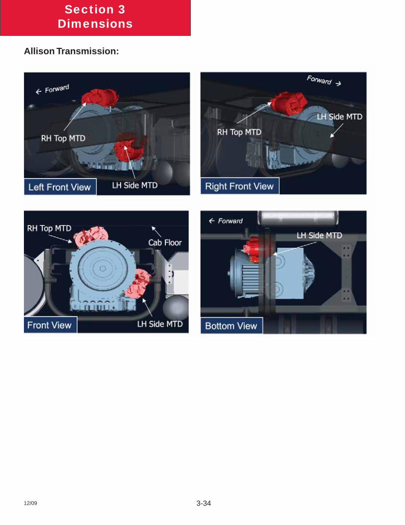
Allison Transmission:
12/09 4-1
Section 4Exhaust & Aftertreatment
EXHAUST AND AFTER-TREATMENT INFORMATIONThe following section is designed to give you information regarding the exhaust and after-treatment systems on Kenworth chassis.
All Kenworth’s equipped with 2010 emission level engines will utilize Selective Catalyst Reduction (SCR). SCR is a process in which Diesel Exhaust Fluid (DEF) is injected into the exhaust down stream of the engine. DEF is converted to ammonia by the heat of the exhaust system. Inside of the SCR canister a catalyst causes a chemical reaction to occur between the ammonia and NOx, turning it into water and nitrogen. For more information on the specifi c details of how SCR works, please contact your local Kenworth dealer.
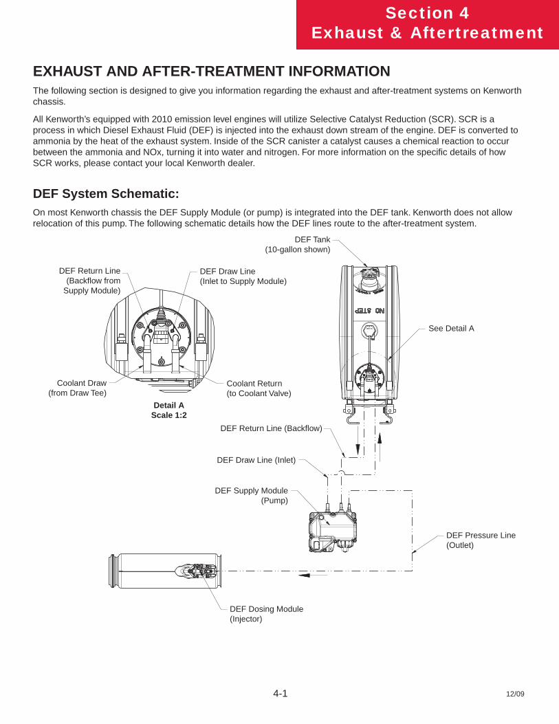
DEF System Schematic:On most Kenworth chassis the DEF Supply Module (or pump) is integrated into the DEF tank. Kenworth does not allow relocation of this pump. The following schematic details how the DEF lines route to the after-treatment system.
DEF Return Line(Backfl ow from
Supply Module)
Coolant Draw(from Draw Tee)
Detail AScale 1:2
DEF Draw Line(Inlet to Supply Module)
Coolant Return(to Coolant Valve)
DEF Tank(10-gallon shown)
See Detail A
DEF Return Line (Backfl ow)
DEF Draw Line (Inlet)
DEF Supply Module(Pump)
DEF Pressure Line (Outlet)
DEF Dosing Module(Injector)
12/09 4-2
Section 4Exhaust & Aftertreatment
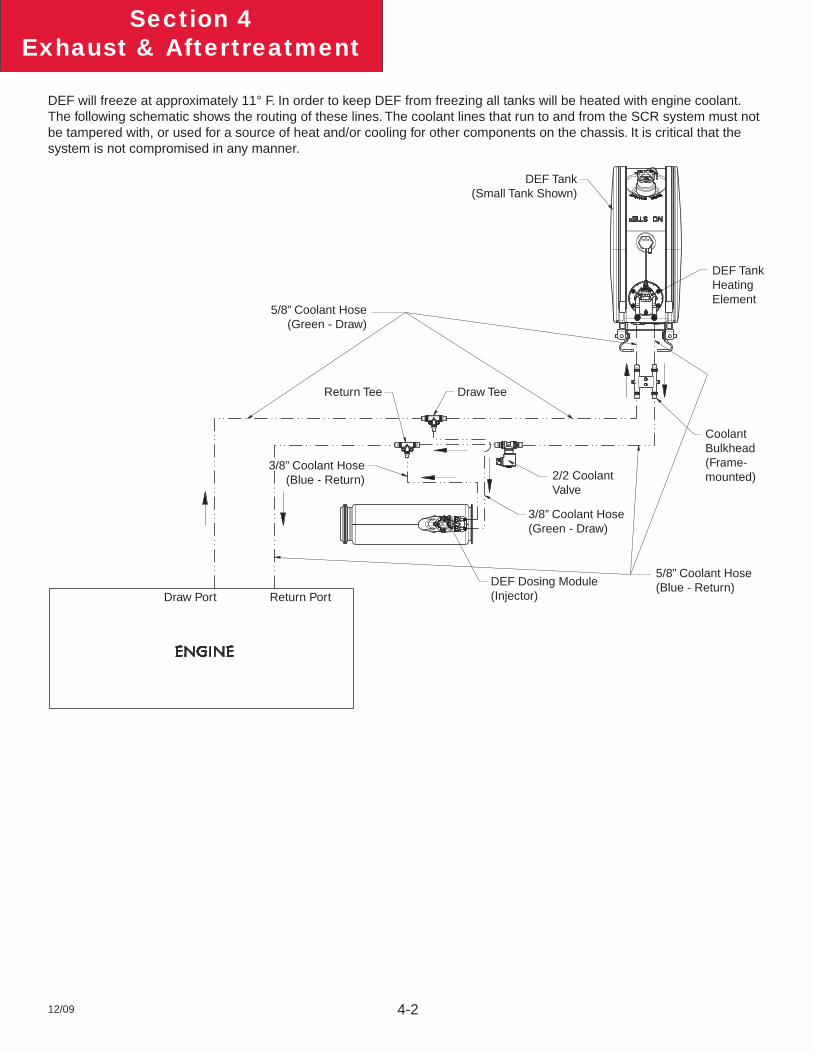
DEF will freeze at approximately 11° F. In order to keep DEF from freezing all tanks will be heated with engine coolant. The following schematic shows the routing of these lines. The coolant lines that run to and from the SCR system must not be tampered with, or used for a source of heat and/or cooling for other components on the chassis. It is critical that the system is not compromised in any manner.
DEF Tank(Small Tank Shown)
DEF TankHeating Element
5/8” Coolant Hose(Green - Draw)
Return Tee Draw Tee
Coolant Bulkhead(Frame-mounted)
3/8” Coolant Hose(Blue - Return) 2/2 Coolant
Valve
3/8” Coolant Hose(Green - Draw)
DEF Dosing Module(Injector)
5/8” Coolant Hose(Blue - Return)
Draw Port Return Port
12/09 4-3
Section 4Exhaust & Aftertreatment
GENERAL GUIDELINES FOR DEF SYSTEMThe installation of the DEF tank is a critical component of the SCR system. While Kenworth does not recommended relo-cating the DEF tank, there are applications and body installations that will require it. The guidelines below must be strictly followed by any entity relocating the tank. Failure to follow the guidelines completely and accurately may result in engine shutdown situations.
Kenworth offers a variety of DEF tank sizes to meet every application. The DEF tank volume is regulated by the E.P.A. Kenworth advises against modifying the tank volume after the truck has been delivered from the factory.
• Total DEF capacity must meet or exceed 6% of the usable fuel capacity on the truck. The calcula-tion to determine DEF capacity is:
Minimum DEF Tank Volume = Useable Fuel Capacity (gal) x 0.06
Example: For a truck with 200 useable gallons of fuel, the equation is DEF required = 200 x 0.06 = 12 gallons or more of DEF.
PACCAR-approved DEF hoses are required when retrofi tting for system to function properly. The use of unapproved hoses for DEF lines will void warranty and may cause engine shutdown situations. The DEF pump (or Supply Module) can not be relocated from the DEF tank.
INSTALLATION REQUIREMENTS AND DIMENSIONS FOR DEF SYSTEMWhen relocating any DEF system components, the locations must meet the guidelines below. Failure to comply may result in non-conformance to EPA standards and engine shutdown.
DEF piping relative heights: In order to ensure proper functionality of DEF system, the height differences in the guidelines below must be followed during line routing and component placement.
With all relocating procedures, general clearances and routing guidelines must be followed. See section 9 of this manual for general routing guidelines.
When relocating the components the maximum pressure DEF hose length, from Supply module to Dosing Module, is 3 meters (118”).
Maintain a minimum of 3” clearance to shielded exhaust components when routing DEF lines to prevent possible melting.
If the DEF tank is relocated the coolant lines will need to be modifi ed. During this process if the tank is moved forward on the chassis (ie closer to the engine) it is necessary to remove excess coolant lines and maintain the original routing path. If the tank is moved rearward on the chassis the additional length of cooling line required to complete the installation must be installed in a straight section of the existing coolant routing lines. This process will minimizes the change in coolant fl ow by minimizing changes in restrictions. Increases in restriction occur with excessive line length and bends. Work with your local Kenworth dealer if you are unsure about the coolant line modifi cations.
12/09 4-4
Section 4Exhaust & Aftertreatment
MEASUREMENT REFERENCE POINTSFor all relocation procedures, the measurement points referenced in the guidelines are taken from the following specifi c points:
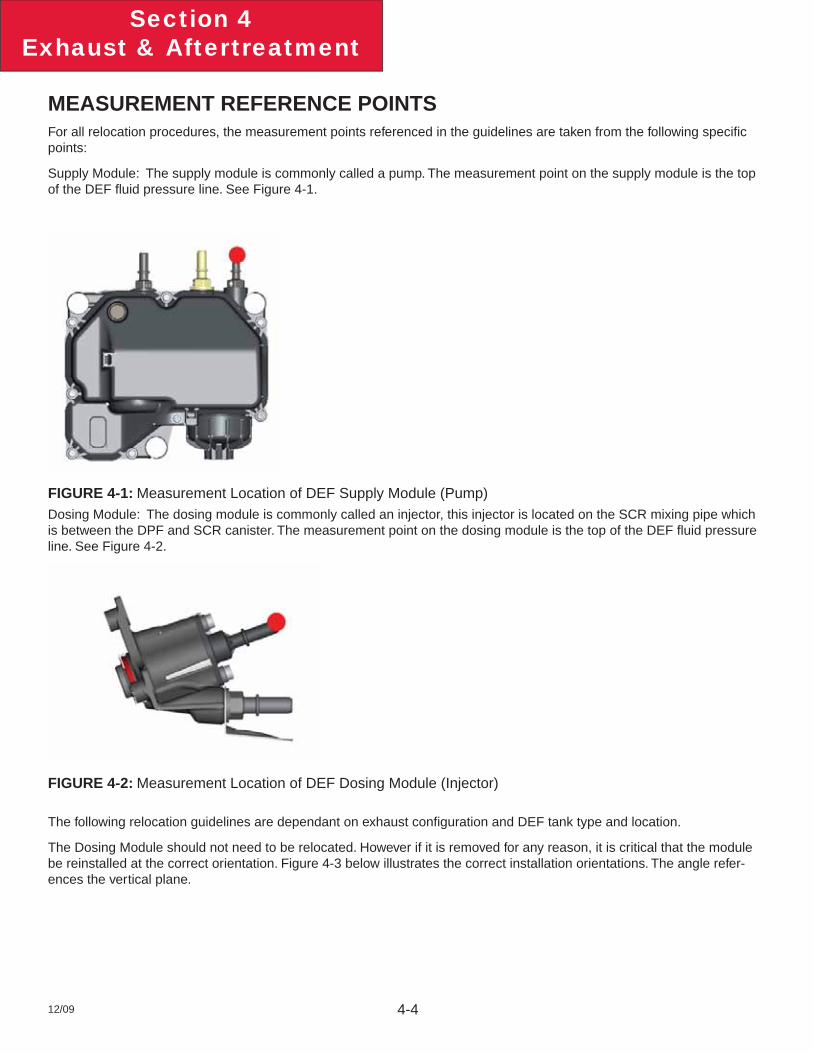
Supply Module: The supply module is commonly called a pump. The measurement point on the supply module is the top of the DEF fl uid pressure line. See Figure 4-1.
FIGURE 4-1: Measurement Location of DEF Supply Module (Pump)Dosing Module: The dosing module is commonly called an injector, this injector is located on the SCR mixing pipe which is between the DPF and SCR canister. The measurement point on the dosing module is the top of the DEF fl uid pressure line. See Figure 4-2.
FIGURE 4-2: Measurement Location of DEF Dosing Module (Injector)
The following relocation guidelines are dependant on exhaust confi guration and DEF tank type and location.
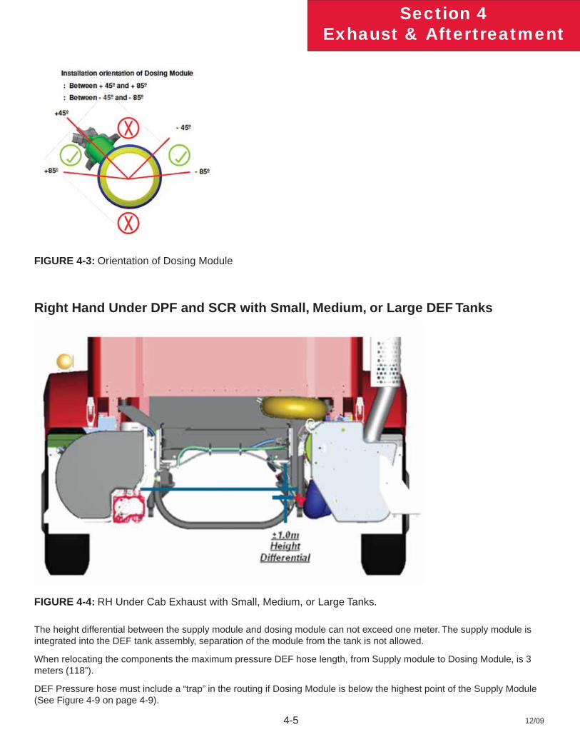
The Dosing Module should not need to be relocated. However if it is removed for any reason, it is critical that the module be reinstalled at the correct orientation. Figure 4-3 below illustrates the correct installation orientations. The angle refer-ences the vertical plane.
12/09 4-5
Section 4Exhaust & Aftertreatment
FIGURE 4-3: Orientation of Dosing Module
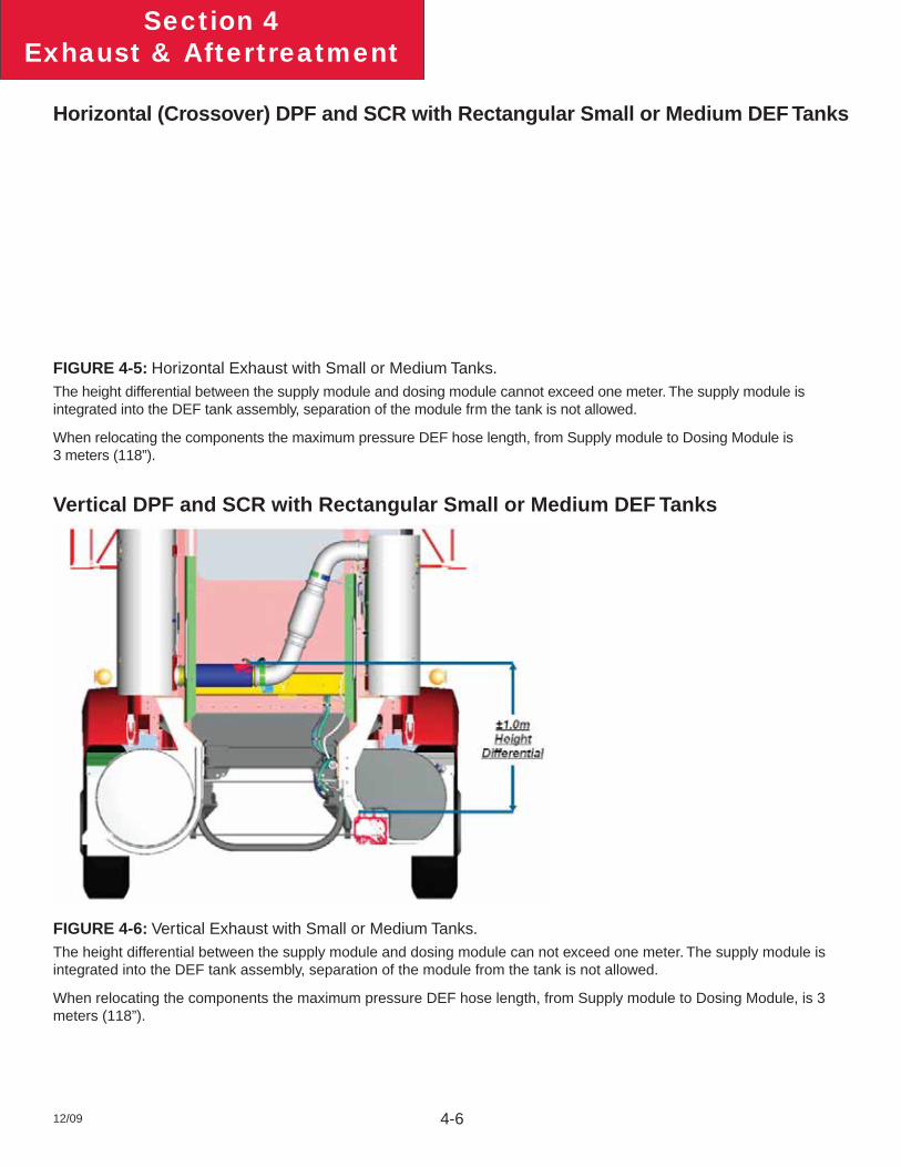
Right Hand Under DPF and SCR with Small, Medium, or Large DEF Tanks
FIGURE 4-4: RH Under Cab Exhaust with Small, Medium, or Large Tanks.
The height differential between the supply module and dosing module can not exceed one meter. The supply module is integrated into the DEF tank assembly, separation of the module from the tank is not allowed.
When relocating the components the maximum pressure DEF hose length, from Supply module to Dosing Module, is 3 meters (118”).
DEF Pressure hose must include a “trap” in the routing if Dosing Module is below the highest point of the Supply Module (See Figure 4-9 on page 4-9).
12/09 4-6
Section 4Exhaust & Aftertreatment
Horizontal (Crossover) DPF and SCR with Rectangular Small or Medium DEF Tanks
FIGURE 4-5: Horizontal Exhaust with Small or Medium Tanks.The height differential between the supply module and dosing module cannot exceed one meter. The supply module is integrated into the DEF tank assembly, separation of the module frm the tank is not allowed.
When relocating the components the maximum pressure DEF hose length, from Supply module to Dosing Module is 3 meters (118”).
Vertical DPF and SCR with Rectangular Small or Medium DEF Tanks
FIGURE 4-6: Vertical Exhaust with Small or Medium Tanks.The height differential between the supply module and dosing module can not exceed one meter. The supply module is integrated into the DEF tank assembly, separation of the module from the tank is not allowed.
When relocating the components the maximum pressure DEF hose length, from Supply module to Dosing Module, is 3 meters (118”).
12/09 4-7
Section 4Exhaust & Aftertreatment
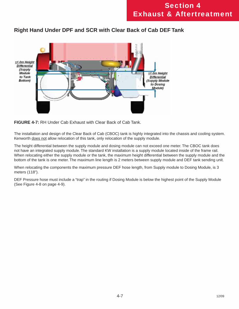
Right Hand Under DPF and SCR with Clear Back of Cab DEF Tank
FIGURE 4-7: RH Under Cab Exhaust with Clear Back of Cab Tank.
The installation and design of the Clear Back of Cab (CBOC) tank is highly integrated into the chassis and cooling system. Kenworth does not allow relocation of this tank, only relocation of the supply module.
The height differential between the supply module and dosing module can not exceed one meter. The CBOC tank does not have an integrated supply module. The standard KW installation is a supply module located inside of the frame rail. When relocating either the supply module or the tank, the maximum height differential between the supply module and the bottom of the tank is one meter. The maximum line length is 2 meters between supply module and DEF tank sending unit.
When relocating the components the maximum pressure DEF hose length, from Supply module to Dosing Module, is 3 meters (118”).
DEF Pressure hose must include a “trap” in the routing if Dosing Module is below the highest point of the Supply Module (See Figure 4-8 on page 4-9).
12/09 4-8
Section 4Exhaust & Aftertreatment
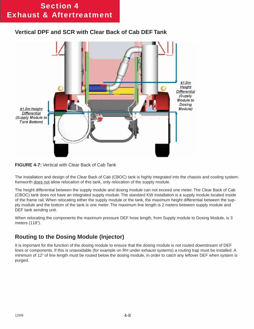
Vertical DPF and SCR with Clear Back of Cab DEF Tank
FIGURE 4-7: Vertical with Clear Back of Cab Tank
The installation and design of the Clear Back of Cab (CBOC) tank is highly integrated into the chassis and cooling system. Kenworth does not allow relocation of this tank, only relocation of the supply module.
The height differential between the supply module and dosing module can not exceed one meter. The Clear Back of Cab (CBOC) tank does not have an integrated supply module. The standard KW installation is a supply module located inside of the frame rail. When relocating either the supply module or the tank, the maximum height differential between the sup-ply module and the bottom of the tank is one meter. The maximum line length is 2 meters between supply module and DEF tank sending unit.
When relocating the components the maximum pressure DEF hose length, from Supply module to Dosing Module, is 3 meters (118”).
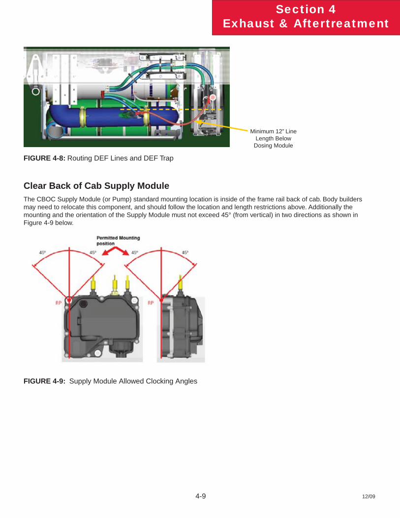
Routing to the Dosing Module (Injector)It is important for the function of the dosing module to ensure that the dosing module is not routed downstream of DEF lines or components. If this is unavoidable (for example on RH under exhaust systems) a routing trap must be installed. A minimum of 12” of line length must be routed below the dosing module, in order to catch any leftover DEF when system is purged.
12/09 4-9
Section 4Exhaust & Aftertreatment
FIGURE 4-8: Routing DEF Lines and DEF Trap
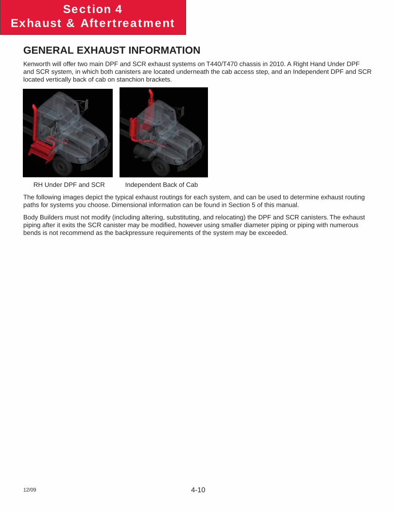
Clear Back of Cab Supply ModuleThe CBOC Supply Module (or Pump) standard mounting location is inside of the frame rail back of cab. Body builders may need to relocate this component, and should follow the location and length restrictions above. Additionally the mounting and the orientation of the Supply Module must not exceed 45° (from vertical) in two directions as shown in Figure 4-9 below.
FIGURE 4-9: Supply Module Allowed Clocking Angles
Minimum 12” Line Length Below
Dosing Module
12/09 4-10
Section 4Exhaust & Aftertreatment
GENERAL EXHAUST INFORMATIONKenworth will offer two main DPF and SCR exhaust systems on T440/T470 chassis in 2010. A Right Hand Under DPF and SCR system, in which both canisters are located underneath the cab access step, and an Independent DPF and SCR located vertically back of cab on stanchion brackets.
RH Under DPF and SCR Independent Back of Cab
The following images depict the typical exhaust routings for each system, and can be used to determine exhaust routing paths for systems you choose. Dimensional information can be found in Section 5 of this manual.
Body Builders must not modify (including altering, substituting, and relocating) the DPF and SCR canisters. The exhaust piping after it exits the SCR canister may be modifi ed, however using smaller diameter piping or piping with numerous bends is not recommend as the backpressure requirements of the system may be exceeded.
12/09 4-11
Section 4Exhaust & Aftertreatment
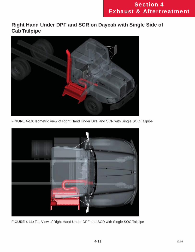
Right Hand Under DPF and SCR on Daycab with Single Side of Cab Tailpipe
FIGURE 4-10: Isometric View of Right Hand Under DPF and SCR with Single SOC Tailpipe
FIGURE 4-11: Top View of Right Hand Under DPF and SCR with Single SOC Tailpipe
12/09 4-12
Section 4Exhaust & Aftertreatment
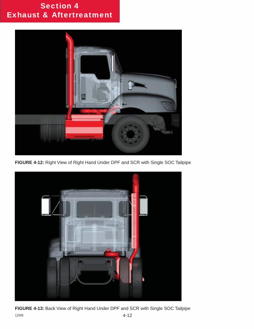
FIGURE 4-12: Right View of Right Hand Under DPF and SCR with Single SOC Tailpipe
FIGURE 4-13: Back View of Right Hand Under DPF and SCR with Single SOC Tailpipe
12/09 4-13
Section 4Exhaust & Aftertreatment
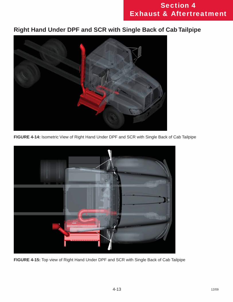
Right Hand Under DPF and SCR with Single Back of Cab Tailpipe
FIGURE 4-14: Isometric View of Right Hand Under DPF and SCR with Single Back of Cab Tailpipe
FIGURE 4-15: Top view of Right Hand Under DPF and SCR with Single Back of Cab Tailpipe
12/09 4-14
Section 4Exhaust & Aftertreatment
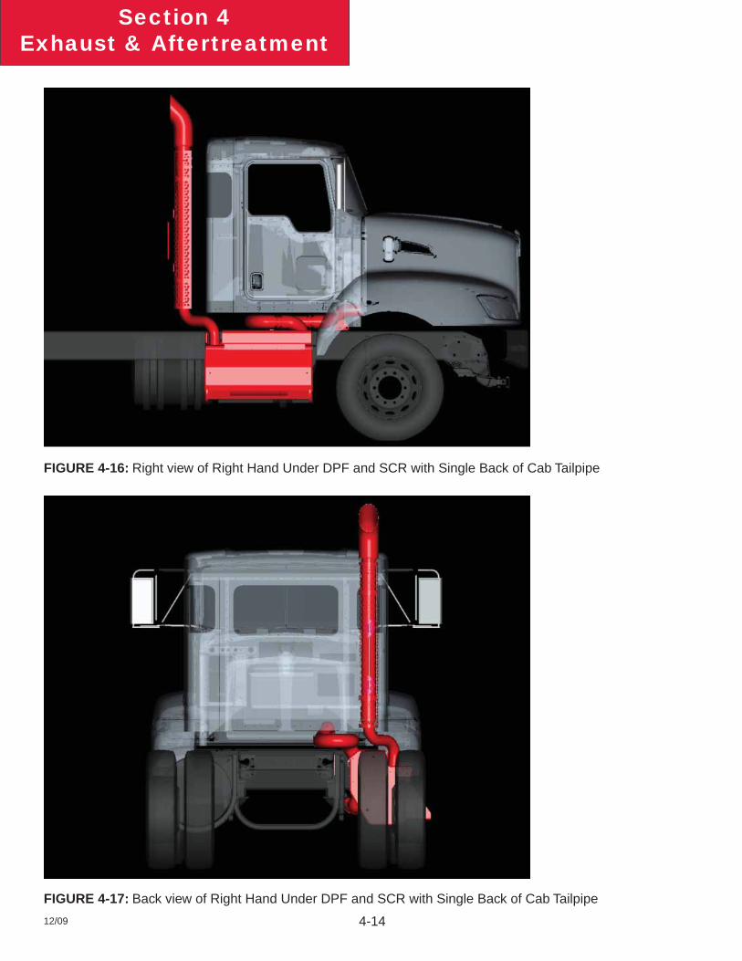
FIGURE 4-16: Right view of Right Hand Under DPF and SCR with Single Back of Cab Tailpipe
FIGURE 4-17: Back view of Right Hand Under DPF and SCR with Single Back of Cab Tailpipe
12/09 4-15
Section 4Exhaust & Aftertreatment
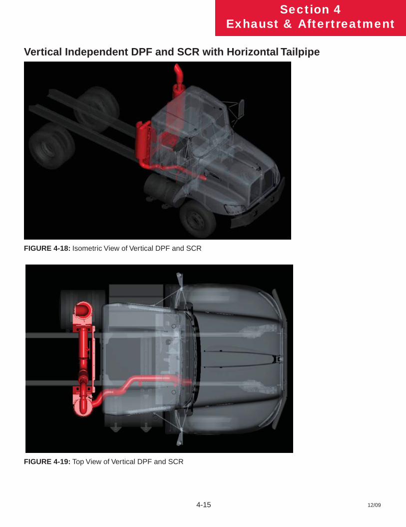
Vertical Independent DPF and SCR with Horizontal Tailpipe
FIGURE 4-18: Isometric View of Vertical DPF and SCR
FIGURE 4-19: Top View of Vertical DPF and SCR
12/09 4-16
Section 4Exhaust & Aftertreatment
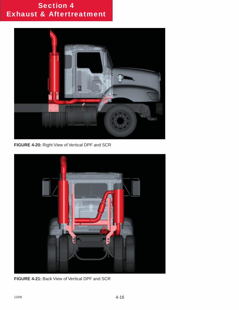
FIGURE 4-20: Right View of Vertical DPF and SCR
FIGURE 4-21: Back View of Vertical DPF and SCR
12/09 4-17
Section 4Exhaust & Aftertreatment
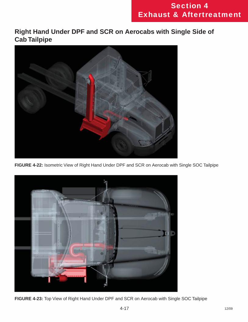
Right Hand Under DPF and SCR on Aerocabs with Single Side of Cab Tailpipe
FIGURE 4-22: Isometric View of Right Hand Under DPF and SCR on Aerocab with Single SOC Tailpipe
FIGURE 4-23: Top View of Right Hand Under DPF and SCR on Aerocab with Single SOC Tailpipe
12/09 4-18
Section 4Exhaust & Aftertreatment
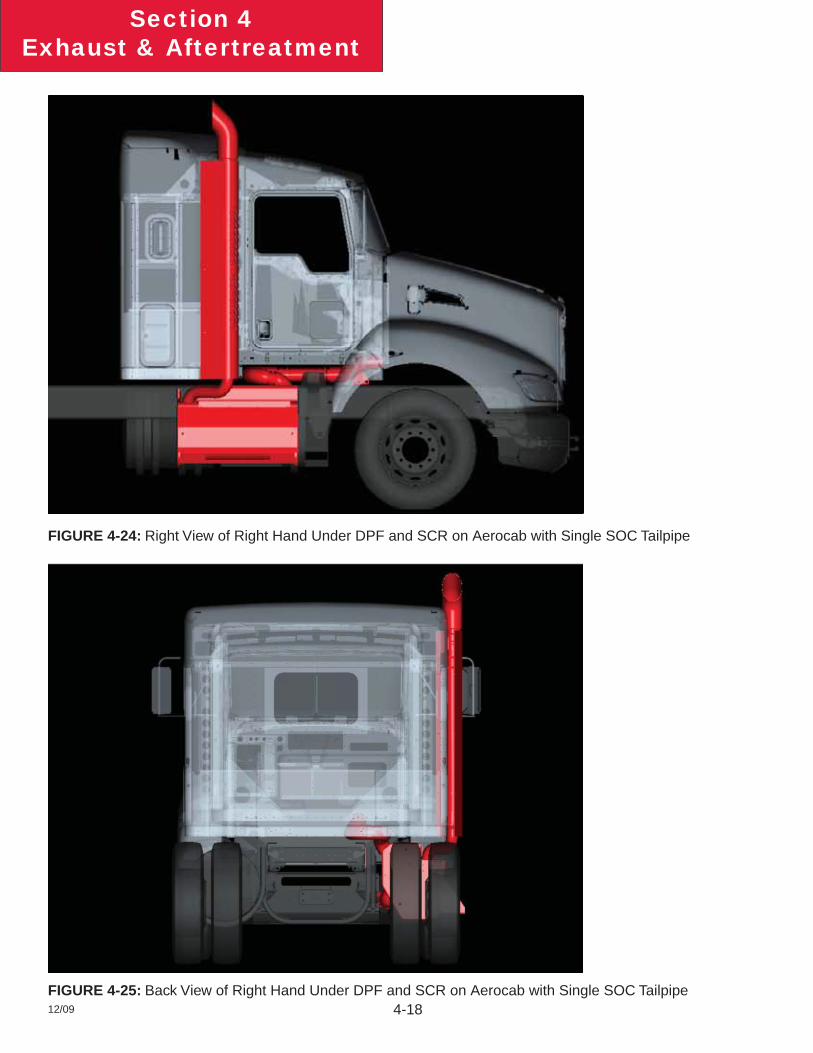
FIGURE 4-24: Right View of Right Hand Under DPF and SCR on Aerocab with Single SOC Tailpipe
FIGURE 4-25: Back View of Right Hand Under DPF and SCR on Aerocab with Single SOC Tailpipe
12/09 4-19
Section 4Exhaust & Aftertreatment
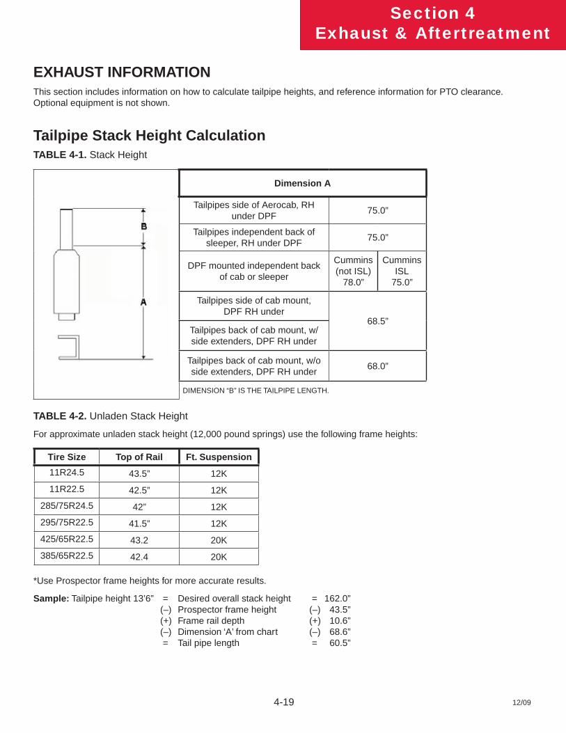
EXHAUST INFORMATIONThis section includes information on how to calculate tailpipe heights, and reference information for PTO clearance. Optional equipment is not shown.
Tailpipe Stack Height CalculationTABLE 4-1. Stack Height
Dimension A
Tailpipes side of Aerocab, RH under DPF
75.0”
Tailpipes independent back of sleeper, RH under DPF
75.0”
DPF mounted independent back of cab or sleeper
Cummins (not ISL)
78.0”
Cummins ISL
75.0”
Tailpipes side of cab mount, DPF RH under
68.5”Tailpipes back of cab mount, w/side extenders, DPF RH under
Tailpipes back of cab mount, w/o side extenders, DPF RH under
68.0”
DIMENSION “B” IS THE TAILPIPE LENGTH.
TABLE 4-2. Unladen Stack Height
For approximate unladen stack height (12,000 pound springs) use the following frame heights:
Tire Size Top of Rail Ft. Suspension
11R24.5 43.5” 12K
11R22.5 42.5” 12K
285/75R24.5 42” 12K
295/75R22.5 41.5” 12K
425/65R22.5 43.2 20K
385/65R22.5 42.4 20K
*Use Prospector frame heights for more accurate results.
Sample: Tailpipe height 13’6” = Desired overall stack height = 162.0” (–) Prospector frame height (–) 43.5” (+) Frame rail depth (+) 10.6” (–) Dimension ‘A’ from chart (–) 68.6” = Tail pipe length = 60.5”

12/09 4-20
Section 4Exhaust & Aftertreatment
This page intentionally left blank.
12/09
Section 5Frame Layouts
5-1
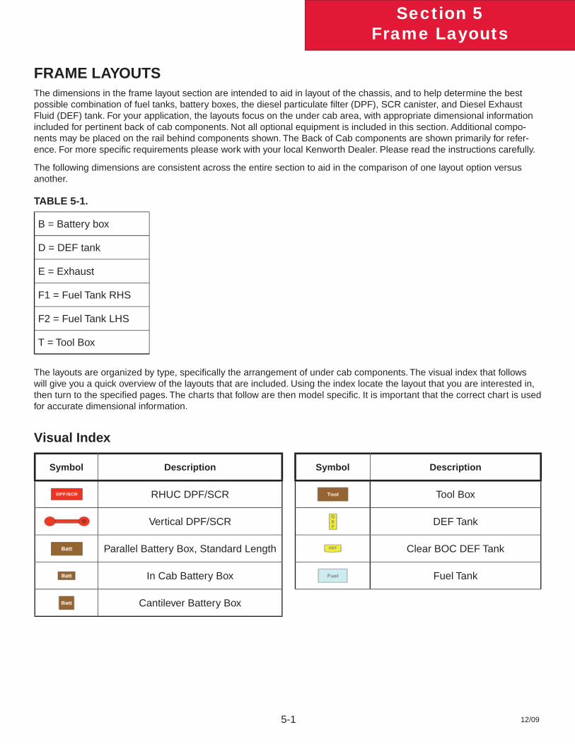
FRAME LAYOUTSThe dimensions in the frame layout section are intended to aid in layout of the chassis, and to help determine the best possible combination of fuel tanks, battery boxes, the diesel particulate fi lter (DPF), SCR canister, and Diesel Exhaust Fluid (DEF) tank. For your application, the layouts focus on the under cab area, with appropriate dimensional information included for pertinent back of cab components. Not all optional equipment is included in this section. Additional compo-nents may be placed on the rail behind components shown. The Back of Cab components are shown primarily for refer-ence. For more specifi c requirements please work with your local Kenworth Dealer. Please read the instructions carefully.
The following dimensions are consistent across the entire section to aid in the comparison of one layout option versus another.
TABLE 5-1.
B = Battery box
D = DEF tank
E = Exhaust
F1 = Fuel Tank RHS
F2 = Fuel Tank LHS
T = Tool Box
The layouts are organized by type, specifi cally the arrangement of under cab components. The visual index that follows will give you a quick overview of the layouts that are included. Using the index locate the layout that you are interested in, then turn to the specifi ed pages. The charts that follow are then model specifi c. It is important that the correct chart is used for accurate dimensional information.
Visual Index
Symbol Description Symbol Description
RHUC DPF/SCR Tool Box
Vertical DPF/SCR DEF Tank
Parallel Battery Box, Standard Length Clear BOC DEF Tank
In Cab Battery Box Fuel Tank
Cantilever Battery Box
12/09 5-2
Section 5Frame Layouts
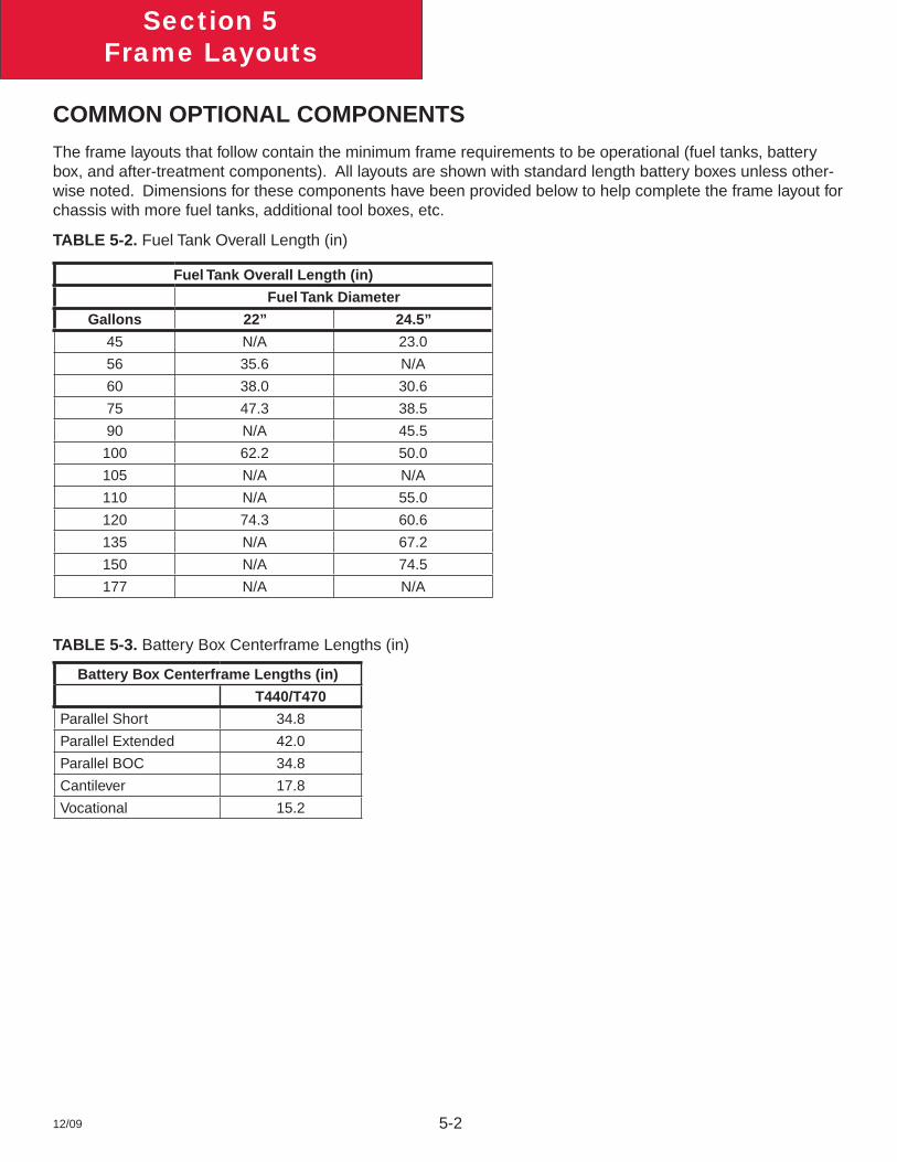
COMMON OPTIONAL COMPONENTS
The frame layouts that follow contain the minimum frame requirements to be operational (fuel tanks, battery box, and after-treatment components). All layouts are shown with standard length battery boxes unless other-wise noted. Dimensions for these components have been provided below to help complete the frame layout for chassis with more fuel tanks, additional tool boxes, etc.
TABLE 5-2. Fuel Tank Overall Length (in)
Fuel Tank Overall Length (in)
Fuel Tank Diameter
Gallons 22” 24.5”
45 N/A 23.0
56 35.6 N/A
60 38.0 30.6
75 47.3 38.5
90 N/A 45.5
100 62.2 50.0
105 N/A N/A
110 N/A 55.0
120 74.3 60.6
135 N/A 67.2
150 N/A 74.5
177 N/A N/A
TABLE 5-3. Battery Box Centerframe Lengths (in)
Battery Box Centerframe Lengths (in)
T440/T470
Parallel Short 34.8
Parallel Extended 42.0
Parallel BOC 34.8
Cantilever 17.8
Vocational 15.2
12/09
Section 5Frame Layouts
5-3
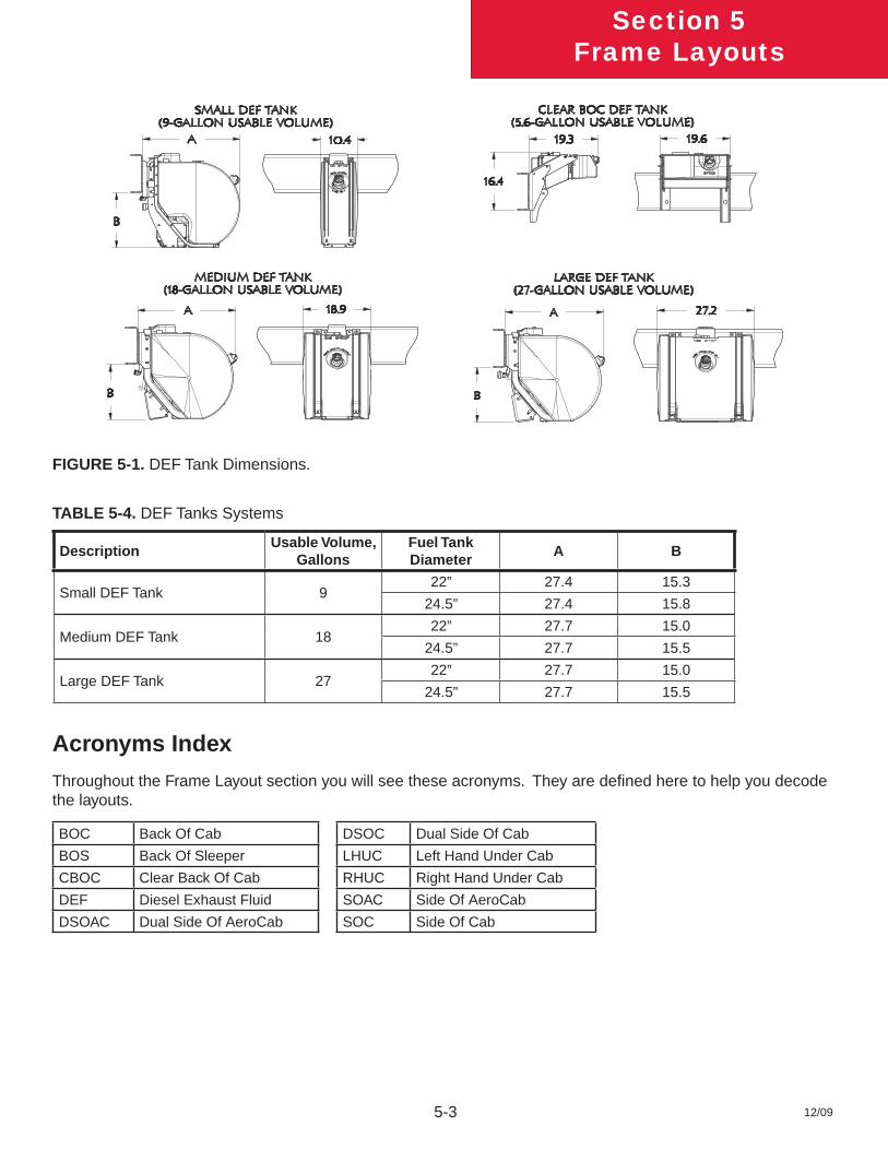
FIGURE 5-1. DEF Tank Dimensions.
TABLE 5-4. DEF Tanks Systems
DescriptionUsable Volume,
GallonsFuel Tank Diameter
A B
Small DEF Tank 922” 27.4 15.3
24.5” 27.4 15.8
Medium DEF Tank 1822” 27.7 15.0
24.5” 27.7 15.5
Large DEF Tank 2722” 27.7 15.0
24.5” 27.7 15.5
Acronyms Index
Throughout the Frame Layout section you will see these acronyms. They are defi ned here to help you decode the layouts.
BOC Back Of Cab DSOC Dual Side Of Cab
BOS Back Of Sleeper LHUC Left Hand Under Cab
CBOC Clear Back Of Cab RHUC Right Hand Under Cab
DEF Diesel Exhaust Fluid SOAC Side Of AeroCab
DSOAC Dual Side Of AeroCab SOC Side Of Cab
12/09 5-4
Section 5Frame Layouts
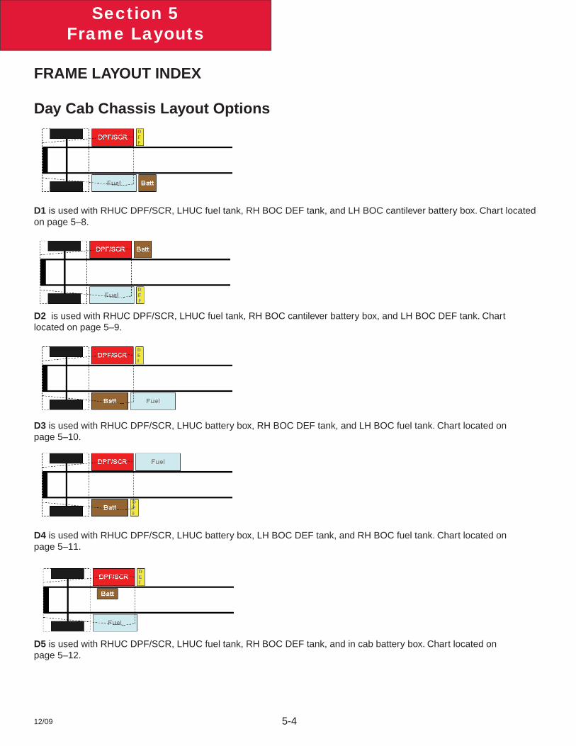
FRAME LAYOUT INDEX
Day Cab Chassis Layout Options
D1 is used with RHUC DPF/SCR, LHUC fuel tank, RH BOC DEF tank, and LH BOC cantilever battery box. Chart located on page 5–8.
D2 is used with RHUC DPF/SCR, LHUC fuel tank, RH BOC cantilever battery box, and LH BOC DEF tank. Chart located on page 5–9.
D3 is used with RHUC DPF/SCR, LHUC battery box, RH BOC DEF tank, and LH BOC fuel tank. Chart located on page 5–10.
D4 is used with RHUC DPF/SCR, LHUC battery box, LH BOC DEF tank, and RH BOC fuel tank. Chart located on page 5–11.
D5 is used with RHUC DPF/SCR, LHUC fuel tank, RH BOC DEF tank, and in cab battery box. Chart located on page 5–12.
12/09
Section 5Frame Layouts
5-5
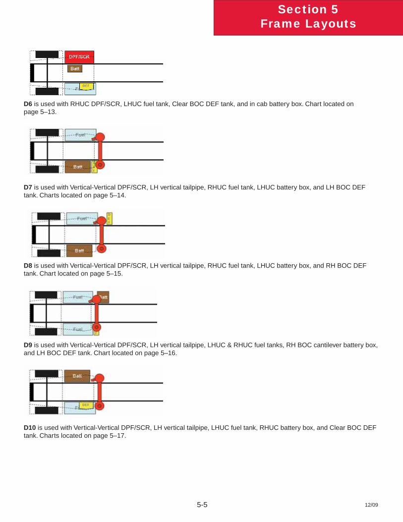
D6 is used with RHUC DPF/SCR, LHUC fuel tank, Clear BOC DEF tank, and in cab battery box. Chart located on page 5–13.
D7 is used with Vertical-Vertical DPF/SCR, LH vertical tailpipe, RHUC fuel tank, LHUC battery box, and LH BOC DEF tank. Charts located on page 5–14.
D8 is used with Vertical-Vertical DPF/SCR, LH vertical tailpipe, RHUC fuel tank, LHUC battery box, and RH BOC DEF tank. Chart located on page 5–15.
D9 is used with Vertical-Vertical DPF/SCR, LH vertical tailpipe, LHUC & RHUC fuel tanks, RH BOC cantilever battery box, and LH BOC DEF tank. Chart located on page 5–16.
D10 is used with Vertical-Vertical DPF/SCR, LH vertical tailpipe, LHUC fuel tank, RHUC battery box, and Clear BOC DEF tank. Charts located on page 5–17.
12/09 5-6
Section 5Frame Layouts
Sleeper Chassis Layout Options
S1 is used with 38” AeroCab sleeper with RHUC DPF/SCR, LHUC fuel tank, RH BOC DEF tank, and LH BOC cantilever battery box. Chart located on page 5–18.
S2 is used with 38” AeroCab sleeper with RHUC DPF/SCR, LHUC fuel tank, LH BOC DEF tank, and RH BOC cantilever battery box. Chart located on page 5–19.
S3 is used with 38” AeroCab sleeper with RHUC DPF/SCR, LHUC battery box, RH BOC DEF tank, and LH BOC fuel tank. Chart located on page 5–20.
S4 is used with 38” AeroCab sleeper with RHUC DPF/SCR, LHUC battery box, LH BOC DEF tank, and RH BOC fuel tank. Chart located on page 5–21.
S5 is used with 38” AeroCab sleeper with Vertical-Vertical DPF/SCR, LH vertical tailpipe, RHUC fuel tank, LHUC battery box, and LH BOC DEF tank. Chart located on page 5–22.
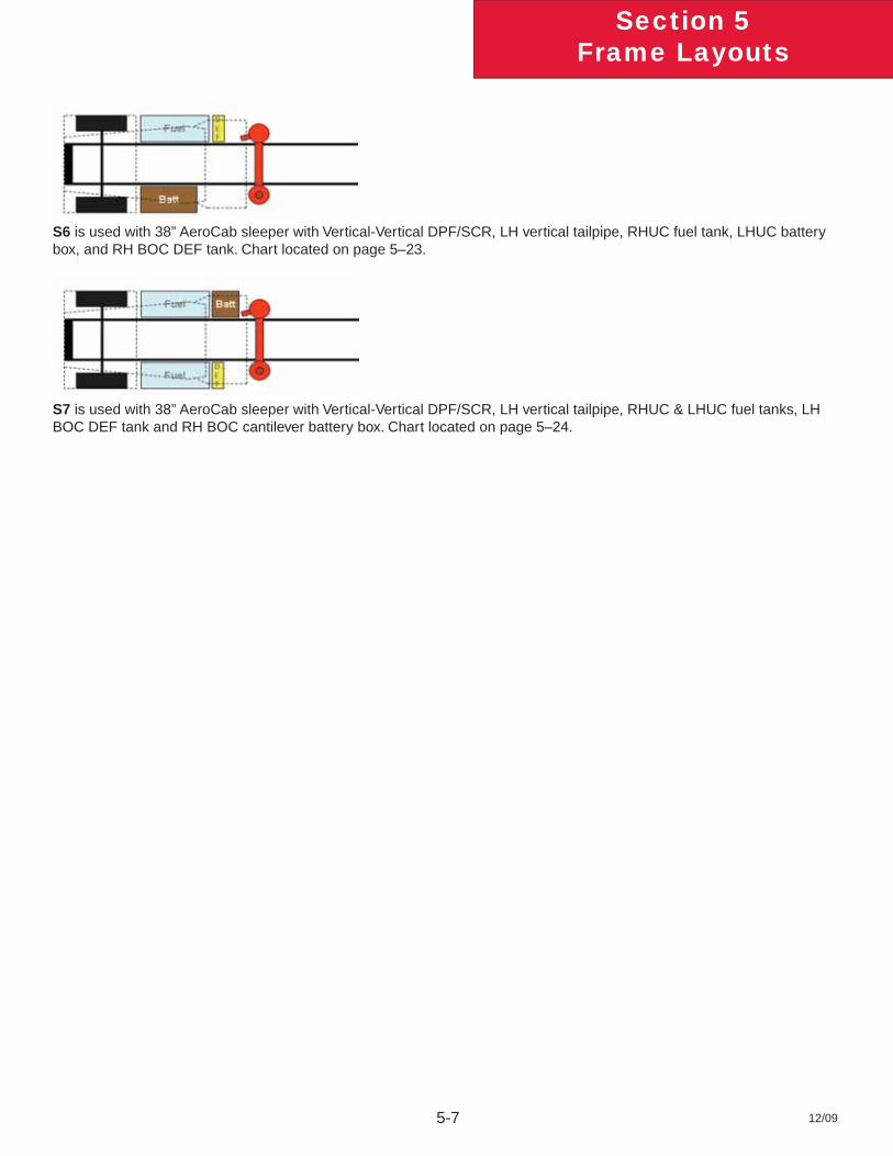
12/09
Section 5Frame Layouts
5-7
S6 is used with 38” AeroCab sleeper with Vertical-Vertical DPF/SCR, LH vertical tailpipe, RHUC fuel tank, LHUC battery box, and RH BOC DEF tank. Chart located on page 5–23.
S7 is used with 38” AeroCab sleeper with Vertical-Vertical DPF/SCR, LH vertical tailpipe, RHUC & LHUC fuel tanks, LH BOC DEF tank and RH BOC cantilever battery box. Chart located on page 5–24.
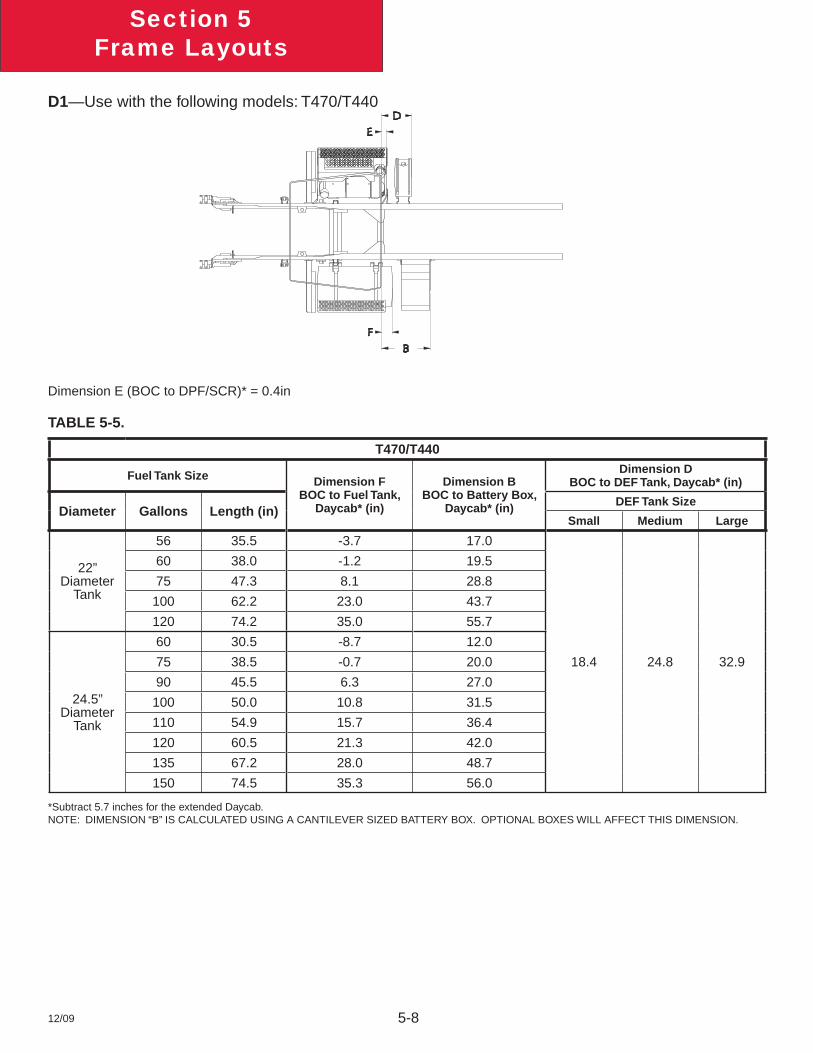
12/09 5-8
Section 5Frame Layouts
D1—Use with the following models: T470/T440
Dimension E (BOC to DPF/SCR)* = 0.4in
TABLE 5-5.
T470/T440
Fuel Tank Size Dimension FBOC to Fuel Tank,
Daycab* (in)
Dimension BBOC to Battery Box,
Daycab* (in)
Dimension DBOC to DEF Tank, Daycab* (in)
Diameter Gallons Length (in)DEF Tank Size
Small Medium Large
22”Diameter
Tank
56 35.5 -3.7 17.0
18.4 24.8 32.9
60 38.0 -1.2 19.5
75 47.3 8.1 28.8
100 62.2 23.0 43.7
120 74.2 35.0 55.7
24.5” Diameter
Tank
60 30.5 -8.7 12.0
75 38.5 -0.7 20.0
90 45.5 6.3 27.0
100 50.0 10.8 31.5
110 54.9 15.7 36.4
120 60.5 21.3 42.0
135 67.2 28.0 48.7
150 74.5 35.3 56.0
*Subtract 5.7 inches for the extended Daycab. NOTE: DIMENSION “B” IS CALCULATED USING A CANTILEVER SIZED BATTERY BOX. OPTIONAL BOXES WILL AFFECT THIS DIMENSION.
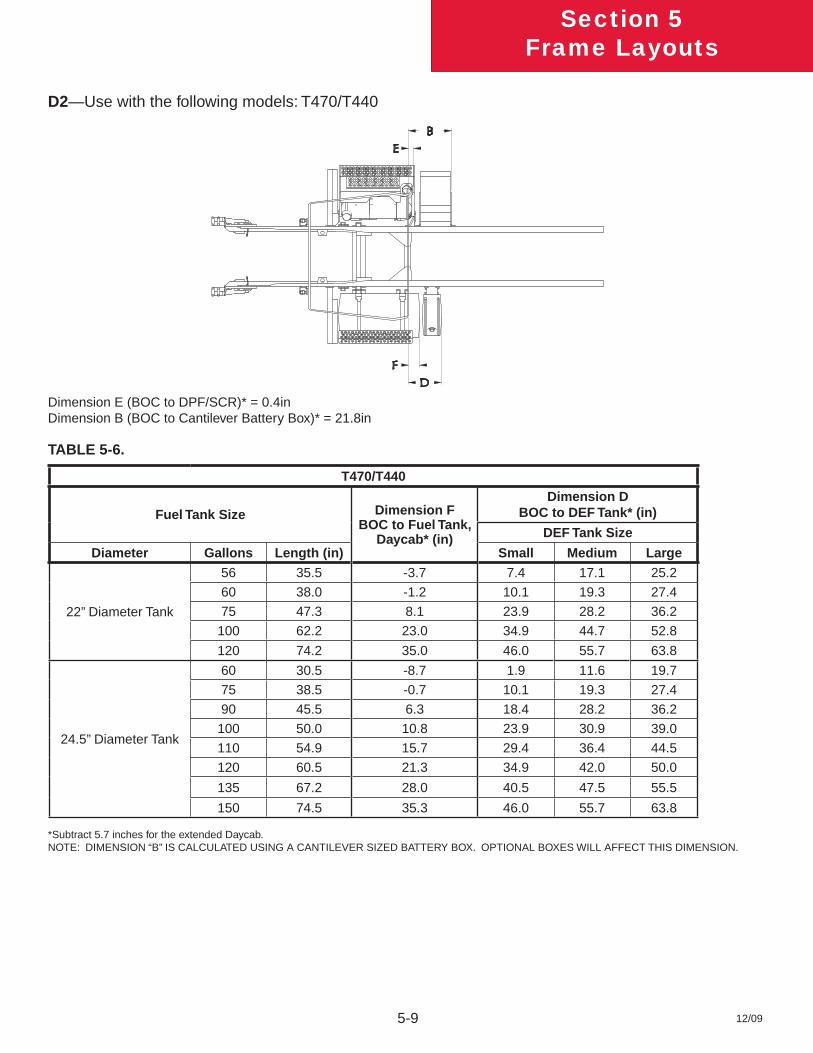
12/09
Section 5Frame Layouts
5-9
D2—Use with the following models: T470/T440
Dimension E (BOC to DPF/SCR)* = 0.4inDimension B (BOC to Cantilever Battery Box)* = 21.8in
TABLE 5-6.
T470/T440
Fuel Tank Size Dimension FBOC to Fuel Tank,
Daycab* (in)
Dimension DBOC to DEF Tank* (in)
DEF Tank Size
Diameter Gallons Length (in) Small Medium Large
22” Diameter Tank
56 35.5 -3.7 7.4 17.1 25.2
60 38.0 -1.2 10.1 19.3 27.4
75 47.3 8.1 23.9 28.2 36.2
100 62.2 23.0 34.9 44.7 52.8
120 74.2 35.0 46.0 55.7 63.8
24.5” Diameter Tank
60 30.5 -8.7 1.9 11.6 19.7
75 38.5 -0.7 10.1 19.3 27.4
90 45.5 6.3 18.4 28.2 36.2
100 50.0 10.8 23.9 30.9 39.0
110 54.9 15.7 29.4 36.4 44.5
120 60.5 21.3 34.9 42.0 50.0
135 67.2 28.0 40.5 47.5 55.5
150 74.5 35.3 46.0 55.7 63.8
*Subtract 5.7 inches for the extended Daycab. NOTE: DIMENSION “B” IS CALCULATED USING A CANTILEVER SIZED BATTERY BOX. OPTIONAL BOXES WILL AFFECT THIS DIMENSION.
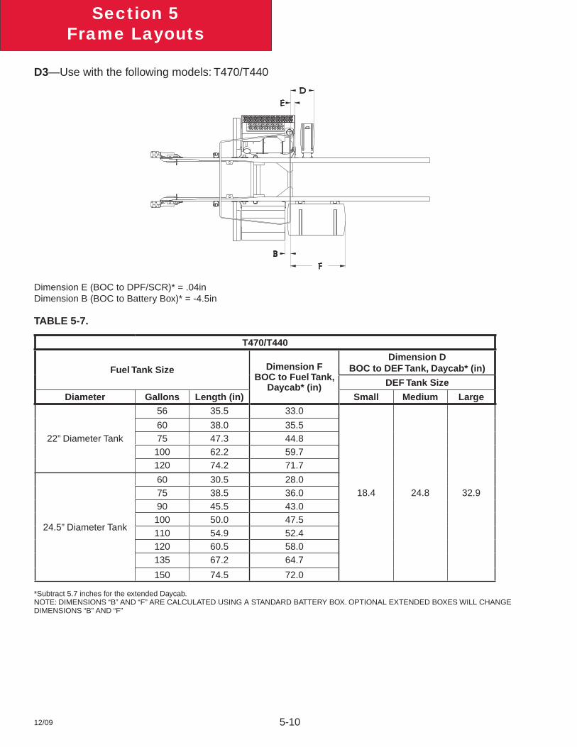
12/09 5-10
Section 5Frame Layouts
D3—Use with the following models: T470/T440
Dimension E (BOC to DPF/SCR)* = .04inDimension B (BOC to Battery Box)* = -4.5in
TABLE 5-7.
T470/T440
Fuel Tank Size Dimension FBOC to Fuel Tank,
Daycab* (in)
Dimension DBOC to DEF Tank, Daycab* (in)
DEF Tank Size
Diameter Gallons Length (in) Small Medium Large
22” Diameter Tank
56 35.5 33.0
18.4 24.8 32.9
60 38.0 35.575 47.3 44.8100 62.2 59.7120 74.2 71.7
24.5” Diameter Tank
60 30.5 28.075 38.5 36.090 45.5 43.0100 50.0 47.5110 54.9 52.4120 60.5 58.0135 67.2 64.7
150 74.5 72.0
*Subtract 5.7 inches for the extended Daycab.NOTE: DIMENSIONS “B” AND “F” ARE CALCULATED USING A STANDARD BATTERY BOX. OPTIONAL EXTENDED BOXES WILL CHANGE DIMENSIONS “B” AND “F”
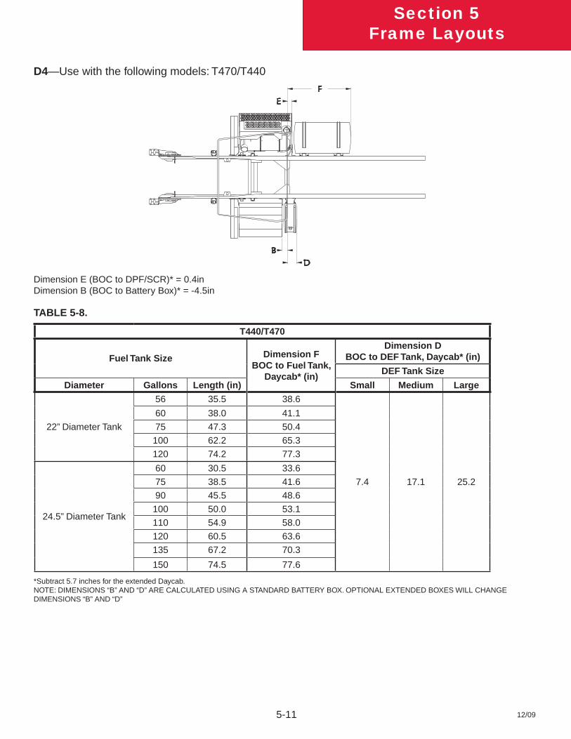
12/09
Section 5Frame Layouts
5-11
D4—Use with the following models: T470/T440
Dimension E (BOC to DPF/SCR)* = 0.4inDimension B (BOC to Battery Box)* = -4.5in
TABLE 5-8.
T440/T470
Fuel Tank Size Dimension FBOC to Fuel Tank,
Daycab* (in)
Dimension DBOC to DEF Tank, Daycab* (in)
DEF Tank Size
Diameter Gallons Length (in) Small Medium Large
22” Diameter Tank
56 35.5 38.6
7.4 17.1 25.2
60 38.0 41.1
75 47.3 50.4
100 62.2 65.3
120 74.2 77.3
24.5” Diameter Tank
60 30.5 33.6
75 38.5 41.6
90 45.5 48.6
100 50.0 53.1
110 54.9 58.0
120 60.5 63.6
135 67.2 70.3
150 74.5 77.6
*Subtract 5.7 inches for the extended Daycab.NOTE: DIMENSIONS “B” AND “D” ARE CALCULATED USING A STANDARD BATTERY BOX. OPTIONAL EXTENDED BOXES WILL CHANGE DIMENSIONS “B” AND “D”
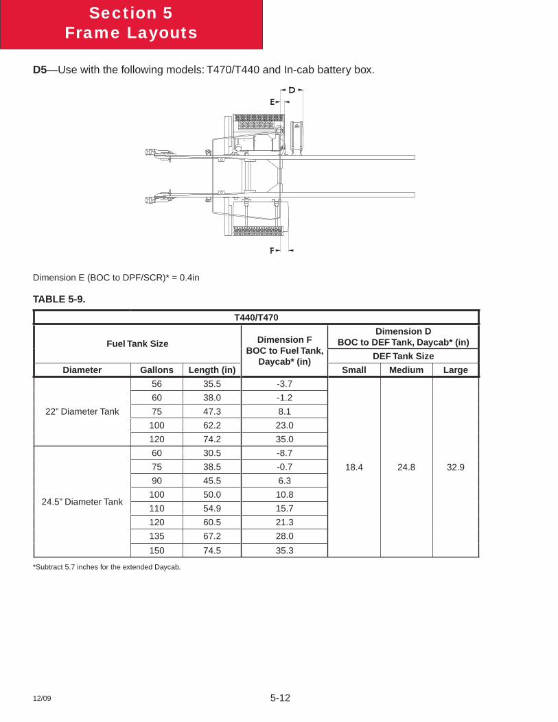
12/09 5-12
Section 5Frame Layouts
D5—Use with the following models: T470/T440 and In-cab battery box.
Dimension E (BOC to DPF/SCR)* = 0.4in
TABLE 5-9.
T440/T470
Fuel Tank Size Dimension FBOC to Fuel Tank,
Daycab* (in)
Dimension DBOC to DEF Tank, Daycab* (in)
DEF Tank Size
Diameter Gallons Length (in) Small Medium Large
22” Diameter Tank
56 35.5 -3.7
18.4 24.8 32.9
60 38.0 -1.2
75 47.3 8.1
100 62.2 23.0
120 74.2 35.0
24.5” Diameter Tank
60 30.5 -8.7
75 38.5 -0.7
90 45.5 6.3
100 50.0 10.8
110 54.9 15.7
120 60.5 21.3
135 67.2 28.0
150 74.5 35.3
*Subtract 5.7 inches for the extended Daycab.
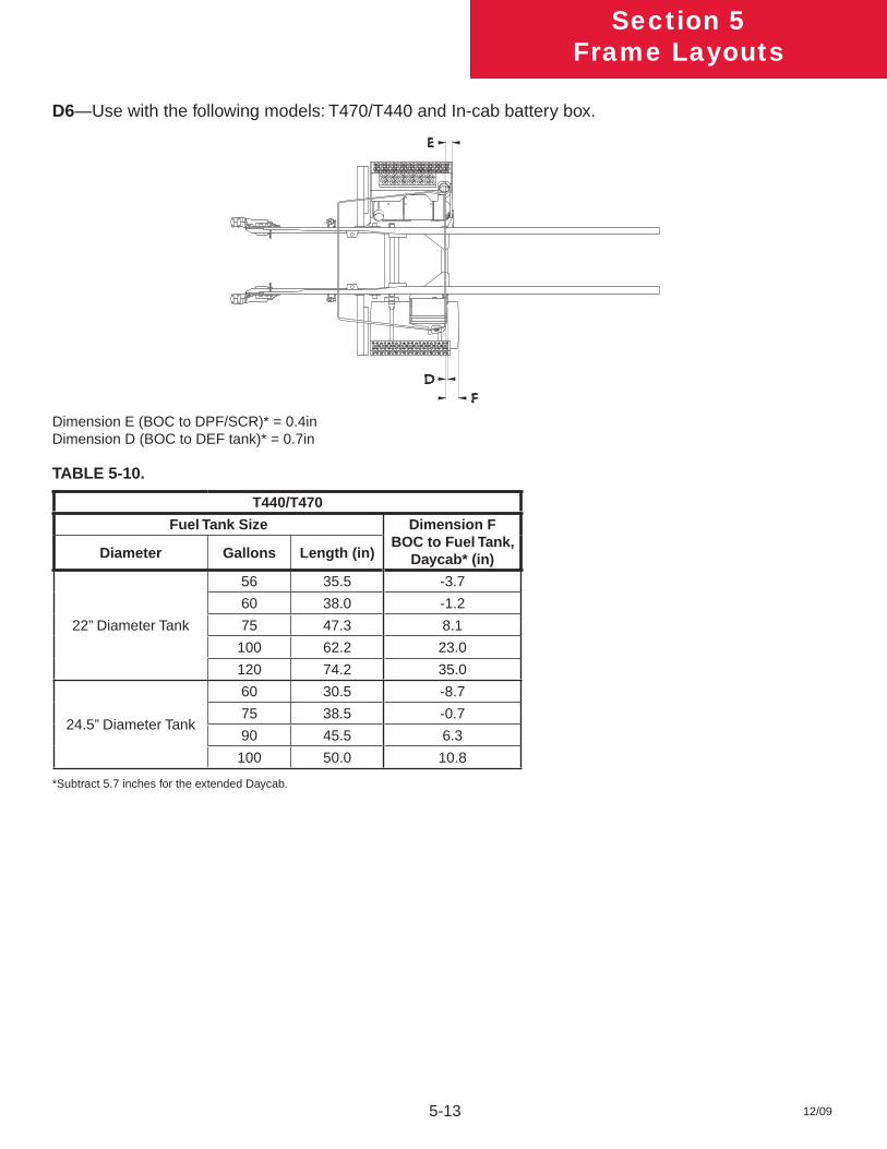
12/09
Section 5Frame Layouts
5-13
D6—Use with the following models: T470/T440 and In-cab battery box.
Dimension E (BOC to DPF/SCR)* = 0.4inDimension D (BOC to DEF tank)* = 0.7in
TABLE 5-10.
T440/T470
Fuel Tank Size Dimension FBOC to Fuel Tank,
Daycab* (in)Diameter Gallons Length (in)
22” Diameter Tank
56 35.5 -3.7
60 38.0 -1.2
75 47.3 8.1
100 62.2 23.0
120 74.2 35.0
24.5” Diameter Tank
60 30.5 -8.7
75 38.5 -0.7
90 45.5 6.3
100 50.0 10.8
*Subtract 5.7 inches for the extended Daycab.
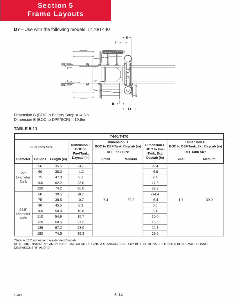
12/09 5-14
Section 5Frame Layouts
D7—Use with the following models: T470/T440
Dimension B (BOC to Battery Box)* = -4.5inDimension E (BOC to DPF/SCR) = 19.6in
TABLE 5-11.
T440/T470
Fuel Tank SizeDimension F
BOC to Fuel Tank,
Daycab (in)
Dimension DBOC to DEF Tank, Daycab (in) Dimension F
BOC to Fuel Tank, Ext.
Daycab (in)
Dimension DBOC to DEF Tank, Ext. Daycab (in)
DEF Tank Size DEF Tank Size
Diameter Gallons Length (in) Small Medium Small Medium
22” Diameter
Tank
56 35.5 -3.7
7.4 39.2
-9.4
1.7 39.0
60 38.0 -1.2 -6.9
75 47.3 8.1 2.4
100 62.2 23.0 17.3
120 74.2 35.0 29.3
24.5” Diameter
Tank
60 30.5 -8.7 -14.4
75 38.5 -0.7 -6.4
90 45.5 6.3 0.6
100 50.0 10.8 5.1
110 54.9 15.7 10.0
120 60.5 21.3 15.6
135 67.2 28.0 22.3
150 74.5 35.3 29.6
*Subtract 5.7 inches for the extended Daycab.NOTE: DIMENSIONS “B” AND “D” ARE CALCULATED USING A STANDARD BATTERY BOX. OPTIONAL EXTENDED BOXES WILL CHANGE DIMENSIONS “B” AND “D”
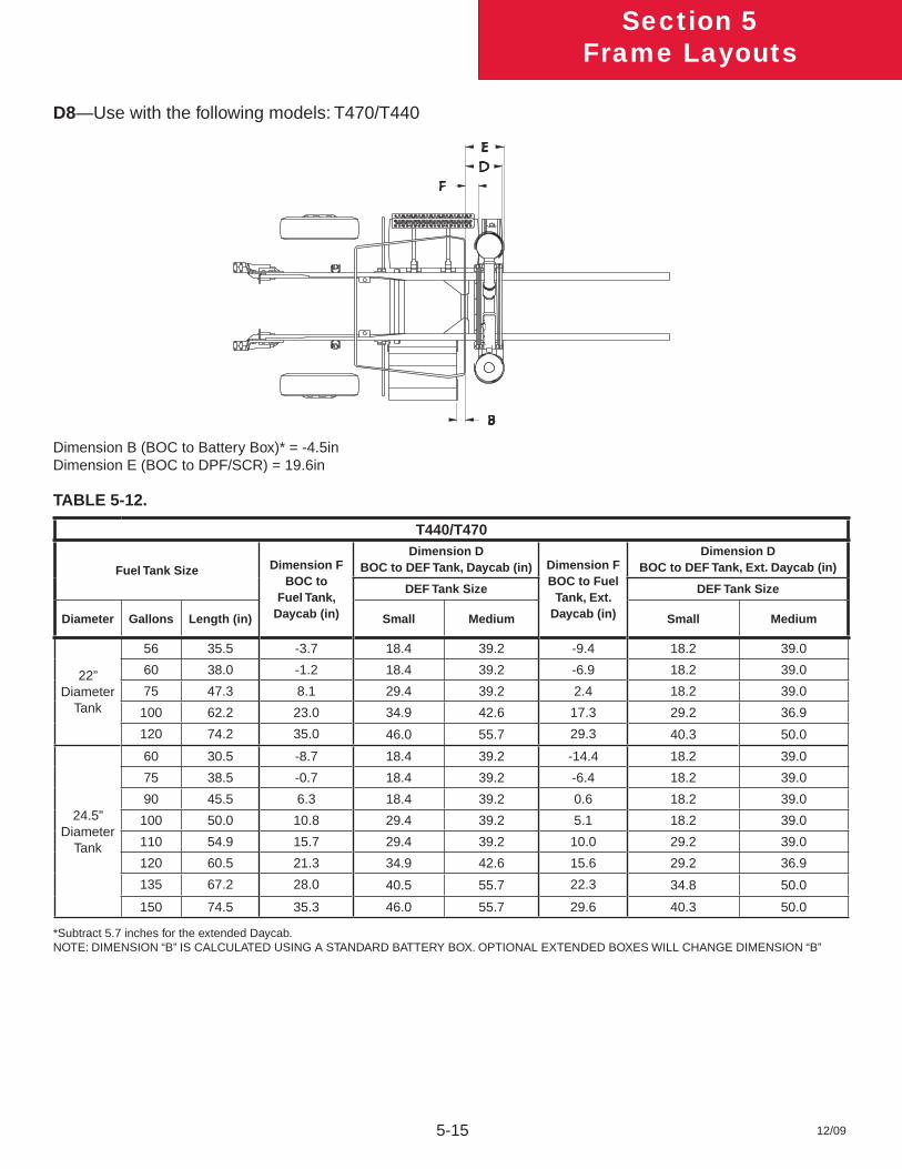
12/09
Section 5Frame Layouts
5-15
D8—Use with the following models: T470/T440
Dimension B (BOC to Battery Box)* = -4.5inDimension E (BOC to DPF/SCR) = 19.6in
TABLE 5-12.
T440/T470
Fuel Tank Size Dimension F BOC to
Fuel Tank, Daycab (in)
Dimension DBOC to DEF Tank, Daycab (in) Dimension F
BOC to Fuel Tank, Ext.
Daycab (in)
Dimension DBOC to DEF Tank, Ext. Daycab (in)
DEF Tank Size DEF Tank Size
Diameter Gallons Length (in) Small Medium Small Medium
22” Diameter
Tank
56 35.5 -3.7 18.4 39.2 -9.4 18.2 39.0
60 38.0 -1.2 18.4 39.2 -6.9 18.2 39.0
75 47.3 8.1 29.4 39.2 2.4 18.2 39.0
100 62.2 23.0 34.9 42.6 17.3 29.2 36.9
120 74.2 35.0 46.0 55.7 29.3 40.3 50.0
24.5” Diameter
Tank
60 30.5 -8.7 18.4 39.2 -14.4 18.2 39.0
75 38.5 -0.7 18.4 39.2 -6.4 18.2 39.0
90 45.5 6.3 18.4 39.2 0.6 18.2 39.0
100 50.0 10.8 29.4 39.2 5.1 18.2 39.0
110 54.9 15.7 29.4 39.2 10.0 29.2 39.0
120 60.5 21.3 34.9 42.6 15.6 29.2 36.9
135 67.2 28.0 40.5 55.7 22.3 34.8 50.0
150 74.5 35.3 46.0 55.7 29.6 40.3 50.0
*Subtract 5.7 inches for the extended Daycab.NOTE: DIMENSION “B” IS CALCULATED USING A STANDARD BATTERY BOX. OPTIONAL EXTENDED BOXES WILL CHANGE DIMENSION “B”
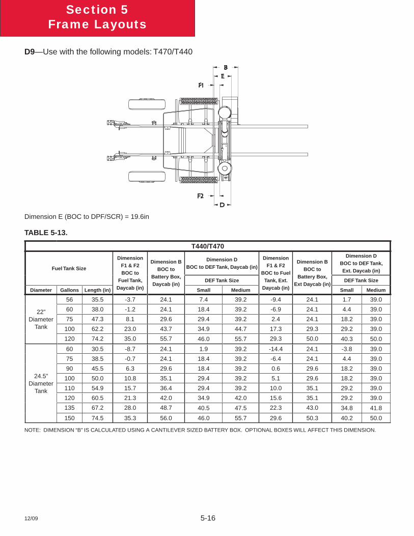
12/09 5-16
Section 5Frame Layouts
D9—Use with the following models: T470/T440
Dimension E (BOC to DPF/SCR) = 19.6in
TABLE 5-13.
T440/T470
Fuel Tank Size
Dimension F1 & F2 BOC to
Fuel Tank, Daycab (in)
Dimension B BOC to
Battery Box, Daycab (in)
Dimension DBOC to DEF Tank, Daycab (in)
Dimension F1 & F2
BOC to Fuel Tank, Ext.
Daycab (in)
Dimension B BOC to
Battery Box, Ext Daycab (in)
Dimension DBOC to DEF Tank, Ext. Daycab (in)
DEF Tank Size DEF Tank Size
Diameter Gallons Length (in) Small Medium Small Medium
22” Diameter
Tank
56 35.5 -3.7 24.1 7.4 39.2 -9.4 24.1 1.7 39.0
60 38.0 -1.2 24.1 18.4 39.2 -6.9 24.1 4.4 39.0
75 47.3 8.1 29.6 29.4 39.2 2.4 24.1 18.2 39.0
100 62.2 23.0 43.7 34.9 44.7 17.3 29.3 29.2 39.0
120 74.2 35.0 55.7 46.0 55.7 29.3 50.0 40.3 50.0
24.5” Diameter
Tank
60 30.5 -8.7 24.1 1.9 39.2 -14.4 24.1 -3.8 39.0
75 38.5 -0.7 24.1 18.4 39.2 -6.4 24.1 4.4 39.0
90 45.5 6.3 29.6 18.4 39.2 0.6 29.6 18.2 39.0
100 50.0 10.8 35.1 29.4 39.2 5.1 29.6 18.2 39.0
110 54.9 15.7 36.4 29.4 39.2 10.0 35.1 29.2 39.0
120 60.5 21.3 42.0 34.9 42.0 15.6 35.1 29.2 39.0
135 67.2 28.0 48.7 40.5 47.5 22.3 43.0 34.8 41.8
150 74.5 35.3 56.0 46.0 55.7 29.6 50.3 40.2 50.0
NOTE: DIMENSION “B” IS CALCULATED USING A CANTILEVER SIZED BATTERY BOX. OPTIONAL BOXES WILL AFFECT THIS DIMENSION.
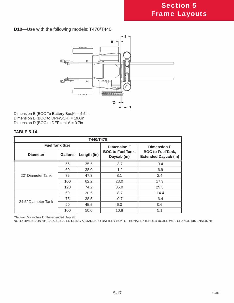
12/09
Section 5Frame Layouts
5-17
D10—Use with the following models: T470/T440
Dimension B (BOC To Battery Box)* = -4.5inDimension E (BOC to DPF/SCR) = 19.6inDimension D (BOC to DEF tank)* = 0.7in
TABLE 5-14.
T440/T470
Fuel Tank Size Dimension F BOC to Fuel Tank,
Daycab (in)
Dimension F BOC to Fuel Tank,
Extended Daycab (in)Diameter Gallons Length (in)
22” Diameter Tank
56 35.5 -3.7 -9.4
60 38.0 -1.2 -6.9
75 47.3 8.1 2.4
100 62.2 23.0 17.3
120 74.2 35.0 29.3
24.5” Diameter Tank
60 30.5 -8.7 -14.4
75 38.5 -0.7 -6.4
90 45.5 6.3 0.6
100 50.0 10.8 5.1
*Subtract 5.7 inches for the extended Daycab.NOTE: DIMENSION “B” IS CALCULATED USING A STANDARD BATTERY BOX. OPTIONAL EXTENDED BOXES WILL CHANGE DIMENSION “B”
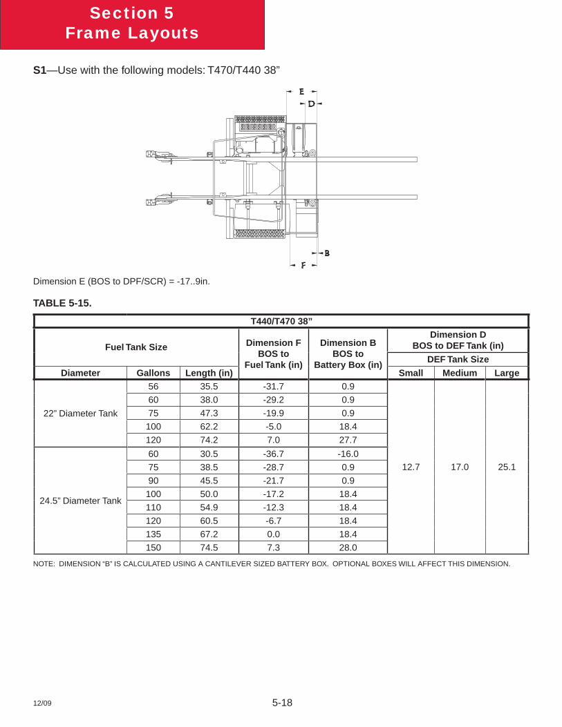
12/09 5-18
Section 5Frame Layouts
S1—Use with the following models: T470/T440 38”
Dimension E (BOS to DPF/SCR) = -17..9in.
TABLE 5-15.
T440/T470 38”
Fuel Tank Size Dimension FBOS to
Fuel Tank (in)
Dimension BBOS to
Battery Box (in)
Dimension DBOS to DEF Tank (in)
DEF Tank Size
Diameter Gallons Length (in) Small Medium Large
22” Diameter Tank
56 35.5 -31.7 0.9
12.7 17.0 25.1
60 38.0 -29.2 0.9
75 47.3 -19.9 0.9
100 62.2 -5.0 18.4
120 74.2 7.0 27.7
24.5” Diameter Tank
60 30.5 -36.7 -16.0
75 38.5 -28.7 0.9
90 45.5 -21.7 0.9
100 50.0 -17.2 18.4
110 54.9 -12.3 18.4
120 60.5 -6.7 18.4
135 67.2 0.0 18.4
150 74.5 7.3 28.0
NOTE: DIMENSION “B” IS CALCULATED USING A CANTILEVER SIZED BATTERY BOX. OPTIONAL BOXES WILL AFFECT THIS DIMENSION.
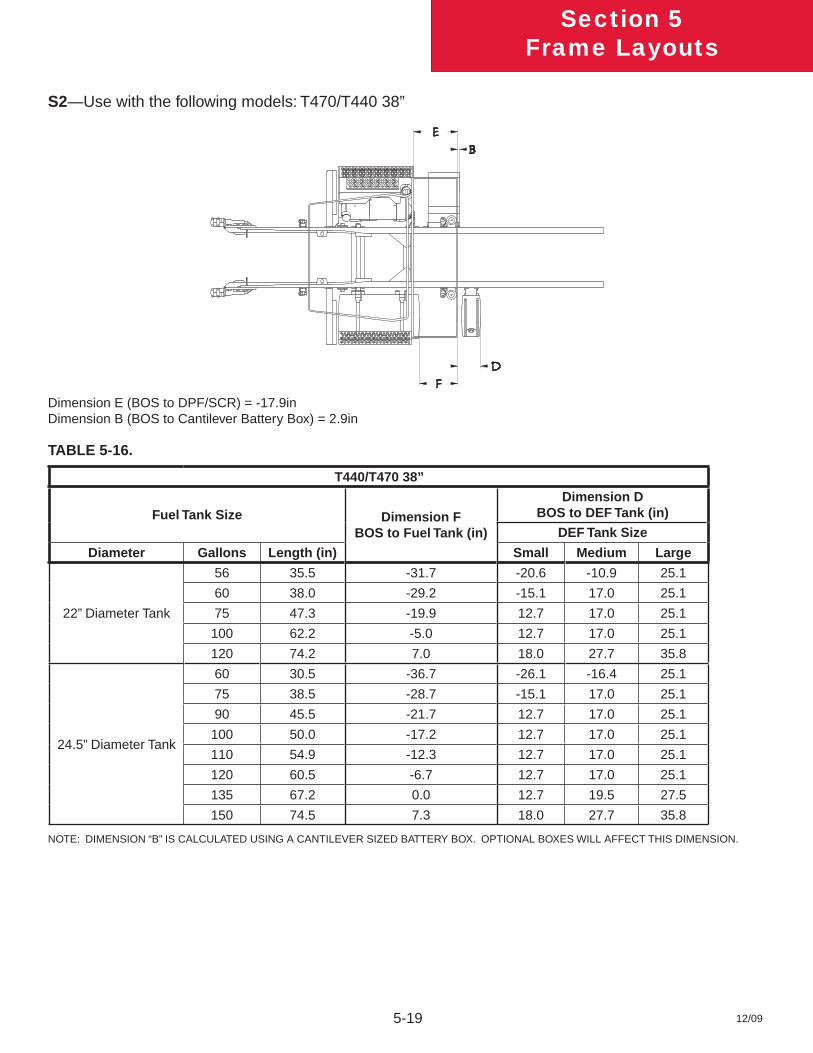
12/09
Section 5Frame Layouts
5-19
S2—Use with the following models: T470/T440 38”
Dimension E (BOS to DPF/SCR) = -17.9inDimension B (BOS to Cantilever Battery Box) = 2.9in
TABLE 5-16.
T440/T470 38”
Fuel Tank Size Dimension FBOS to Fuel Tank (in)
Dimension DBOS to DEF Tank (in)
DEF Tank Size
Diameter Gallons Length (in) Small Medium Large
22” Diameter Tank
56 35.5 -31.7 -20.6 -10.9 25.1
60 38.0 -29.2 -15.1 17.0 25.1
75 47.3 -19.9 12.7 17.0 25.1
100 62.2 -5.0 12.7 17.0 25.1
120 74.2 7.0 18.0 27.7 35.8
24.5” Diameter Tank
60 30.5 -36.7 -26.1 -16.4 25.1
75 38.5 -28.7 -15.1 17.0 25.1
90 45.5 -21.7 12.7 17.0 25.1
100 50.0 -17.2 12.7 17.0 25.1
110 54.9 -12.3 12.7 17.0 25.1
120 60.5 -6.7 12.7 17.0 25.1
135 67.2 0.0 12.7 19.5 27.5
150 74.5 7.3 18.0 27.7 35.8
NOTE: DIMENSION “B” IS CALCULATED USING A CANTILEVER SIZED BATTERY BOX. OPTIONAL BOXES WILL AFFECT THIS DIMENSION.
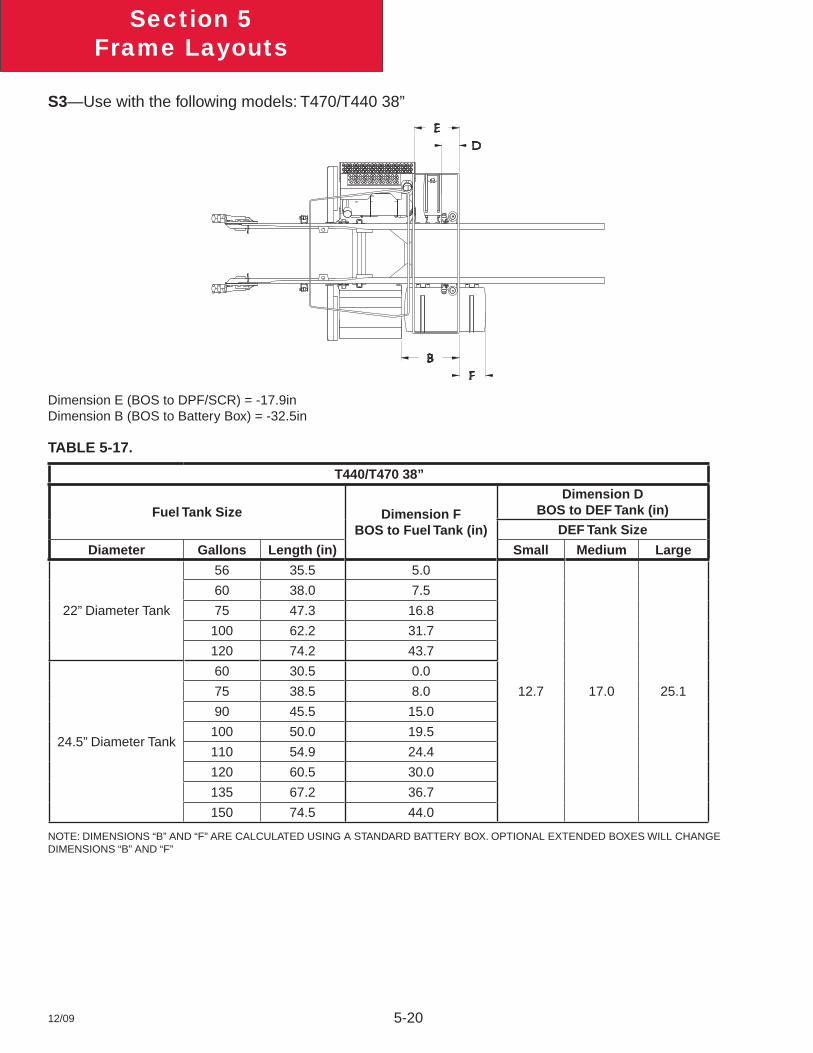
12/09 5-20
Section 5Frame Layouts
S3—Use with the following models: T470/T440 38”
Dimension E (BOS to DPF/SCR) = -17.9inDimension B (BOS to Battery Box) = -32.5in
TABLE 5-17.
T440/T470 38”
Fuel Tank Size Dimension FBOS to Fuel Tank (in)
Dimension DBOS to DEF Tank (in)
DEF Tank Size
Diameter Gallons Length (in) Small Medium Large
22” Diameter Tank
56 35.5 5.0
12.7 17.0 25.1
60 38.0 7.5
75 47.3 16.8
100 62.2 31.7
120 74.2 43.7
24.5” Diameter Tank
60 30.5 0.0
75 38.5 8.0
90 45.5 15.0
100 50.0 19.5
110 54.9 24.4
120 60.5 30.0
135 67.2 36.7
150 74.5 44.0
NOTE: DIMENSIONS “B” AND “F” ARE CALCULATED USING A STANDARD BATTERY BOX. OPTIONAL EXTENDED BOXES WILL CHANGE DIMENSIONS “B” AND “F”
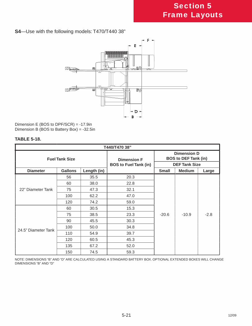
12/09
Section 5Frame Layouts
5-21
S4—Use with the following models: T470/T440 38”
Dimension E (BOS to DPF/SCR) = -17.9inDimension B (BOS to Battery Box) = -32.5in
TABLE 5-18.
T440/T470 38”
Fuel Tank Size Dimension FBOS to Fuel Tank (in)
Dimension DBOS to DEF Tank (in)
DEF Tank Size
Diameter Gallons Length (in) Small Medium Large
22” Diameter Tank
56 35.5 20.3
-20.6 -10.9 -2.8
60 38.0 22.8
75 47.3 32.1
100 62.2 47.0
120 74.2 59.0
24.5” Diameter Tank
60 30.5 15.3
75 38.5 23.3
90 45.5 30.3
100 50.0 34.8
110 54.9 39.7
120 60.5 45.3
135 67.2 52.0
150 74.5 59.3
NOTE: DIMENSIONS “B” AND “D” ARE CALCULATED USING A STANDARD BATTERY BOX. OPTIONAL EXTENDED BOXES WILL CHANGE DIMENSIONS “B” AND “D”
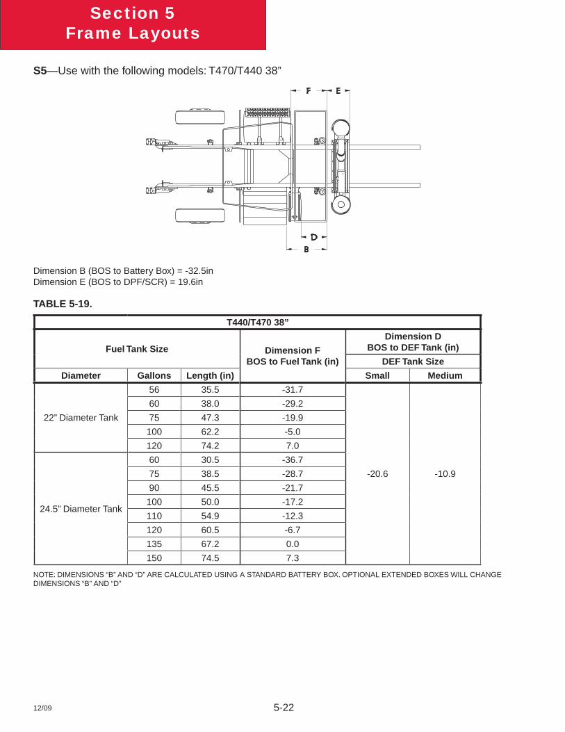
12/09 5-22
Section 5Frame Layouts
S5—Use with the following models: T470/T440 38”
Dimension B (BOS to Battery Box) = -32.5inDimension E (BOS to DPF/SCR) = 19.6in
TABLE 5-19.
T440/T470 38”
Fuel Tank Size Dimension FBOS to Fuel Tank (in)
Dimension DBOS to DEF Tank (in)
DEF Tank Size
Diameter Gallons Length (in) Small Medium
22” Diameter Tank
56 35.5 -31.7
-20.6 -10.9
60 38.0 -29.2
75 47.3 -19.9
100 62.2 -5.0
120 74.2 7.0
24.5” Diameter Tank
60 30.5 -36.7
75 38.5 -28.7
90 45.5 -21.7
100 50.0 -17.2
110 54.9 -12.3
120 60.5 -6.7
135 67.2 0.0
150 74.5 7.3
NOTE: DIMENSIONS “B” AND “D” ARE CALCULATED USING A STANDARD BATTERY BOX. OPTIONAL EXTENDED BOXES WILL CHANGE DIMENSIONS “B” AND “D”
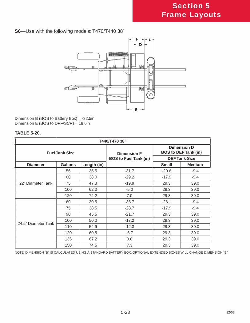
12/09
Section 5Frame Layouts
5-23
S6—Use with the following models: T470/T440 38”
Dimension B (BOS to Battery Box) = -32.5inDimension E (BOS to DPF/SCR) = 19.6in
TABLE 5-20.
T440/T470 38”
Fuel Tank Size Dimension FBOS to Fuel Tank (in)
Dimension DBOS to DEF Tank (in)
DEF Tank Size
Diameter Gallons Length (in) Small Medium
22” Diameter Tank
56 35.5 -31.7 -20.6 -9.4
60 38.0 -29.2 -17.9 -9.4
75 47.3 -19.9 29.3 39.0
100 62.2 -5.0 29.3 39.0
120 74.2 7.0 29.3 39.0
24.5” Diameter Tank
60 30.5 -36.7 -26.1 -9.4
75 38.5 -28.7 -17.9 -9.4
90 45.5 -21.7 29.3 39.0
100 50.0 -17.2 29.3 39.0
110 54.9 -12.3 29.3 39.0
120 60.5 -6.7 29.3 39.0
135 67.2 0.0 29.3 39.0
150 74.5 7.3 29.3 39.0
NOTE: DIMENSION “B” IS CALCULATED USING A STANDARD BATTERY BOX. OPTIONAL EXTENDED BOXES WILL CHANGE DIMENSION “B”
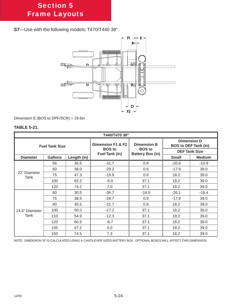
12/09 5-24
Section 5Frame Layouts
S7—Use with the following models: T470/T440 38”
Dimension E (BOS to DPF/SCR) = 19.6in
TABLE 5-21.
T440/T470 38”
Fuel Tank Size Dimension F1 & F2BOS to
Fuel Tank (in)
Dimension BBOS to
Battery Box (in)
Dimension DBOS to DEF Tank (in)
DEF Tank Size
Diameter Gallons Length (in) Small Medium
22” Diameter Tank
56 35.5 -31.7 0.9 -20.6 -10.9
60 38.0 -29.2 0.9 -17.9 39.0
75 47.3 -19.9 0.9 18.2 39.0
100 62.2 -5.0 37.1 18.2 39.0
120 74.2 7.0 37.1 18.2 39.0
24.5” Diameter Tank
60 30.5 -36.7 -16.0 -26.1 -16.4
75 38.5 -28.7 0.9 -17.9 39.0
90 45.5 -21.7 0.9 18.2 39.0
100 50.0 -17.2 37.1 18.2 39.0
110 54.9 -12.3 37.1 18.2 39.0
120 60.5 -6.7 37.1 18.2 39.0
135 67.2 0.0 37.1 18.2 39.0
150 74.5 7.3 37.1 18.2 39.0
NOTE: DIMENSION “B” IS CALCULATED USING A CANTILEVER SIZED BATTERY BOX. OPTIONAL BOXES WILL AFFECT THIS DIMENSION.
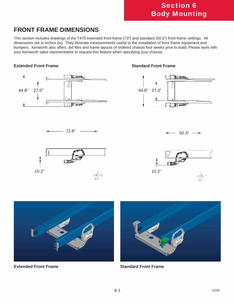
6-1 12/09
Section 6Body Mounting
FRONT FRAME DIMENSIONS
Extended Front Frame Standard Front Frame
Extended Front Frame Standard Front Frame
44.8” 44.8” 27.0”27.0”
72.8”
10.2”
50.3”
10.2”
This section includes drawings of the T470 extended front frame (73”) and standard (50.5”) front frame settings. All dimensions are in inches (in). They illustrate measurements useful to the installation of front frame equipment and bumpers. Kenworth also offers .dxf fi les and frame layouts of ordered chassis four weeks prior to build. Please work with your Kenworth sales representative to request this feature when specifying your chassis.
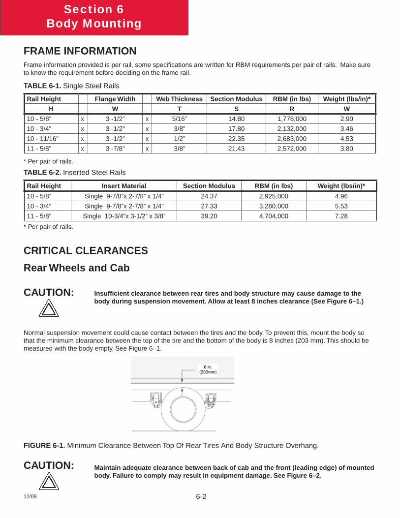
6-212/09
Section 6Body Mounting
FRAME INFORMATIONFrame information provided is per rail, some specifi cations are written for RBM requirements per pair of rails. Make sure to know the requirement before deciding on the frame rail.
TABLE 6-1. Single Steel Rails
Rail Height Flange Width Web Thickness Section Modulus RBM (in lbs) Weight (lbs/in)*
H W T S R W
10 - 5/8” x 3 -1/2” x 5/16” 14.80 1,776,000 2.90
10 - 3/4” x 3 -1/2” x 3/8” 17.80 2,132,000 3.46
10 - 11/16” x 3 -1/2” x 1/2” 22.35 2,683,000 4.53
11 - 5/8” x 3 -7/8” x 3/8” 21.43 2,572,000 3.80
* Per pair of rails.
TABLE 6-2. Inserted Steel Rails
Rail Height Insert Material Section Modulus RBM (in lbs) Weight (lbs/in)*
10 - 5/8” Single 9-7/8”x 2-7/8” x 1/4” 24.37 2,925,000 4.96
10 - 3/4” Single 9-7/8”x 2-7/8” x 1/4” 27.33 3,280,000 5.53
11 - 5/8” Single 10-3/4”x 3-1/2” x 3/8” 39.20 4,704,000 7.28
* Per pair of rails.
CRITICAL CLEARANCES
Rear Wheels and Cab
Insuffi cient clearance between rear tires and body structure may cause damage to the body during suspension movement. Allow at least 8 inches clearance (See Figure 6–1.)
Normal suspension movement could cause contact between the tires and the body. To prevent this, mount the body so that the minimum clearance between the top of the tire and the bottom of the body is 8 inches (203 mm). This should be measured with the body empty. See Figure 6–1.
FIGURE 6-1. Minimum Clearance Between Top Of Rear Tires And Body Structure Overhang.
Maintain adequate clearance between back of cab and the front (leading edge) of mounted body. Failure to comply may result in equipment damage. See Figure 6–2.
CAUTION:
CAUTION:
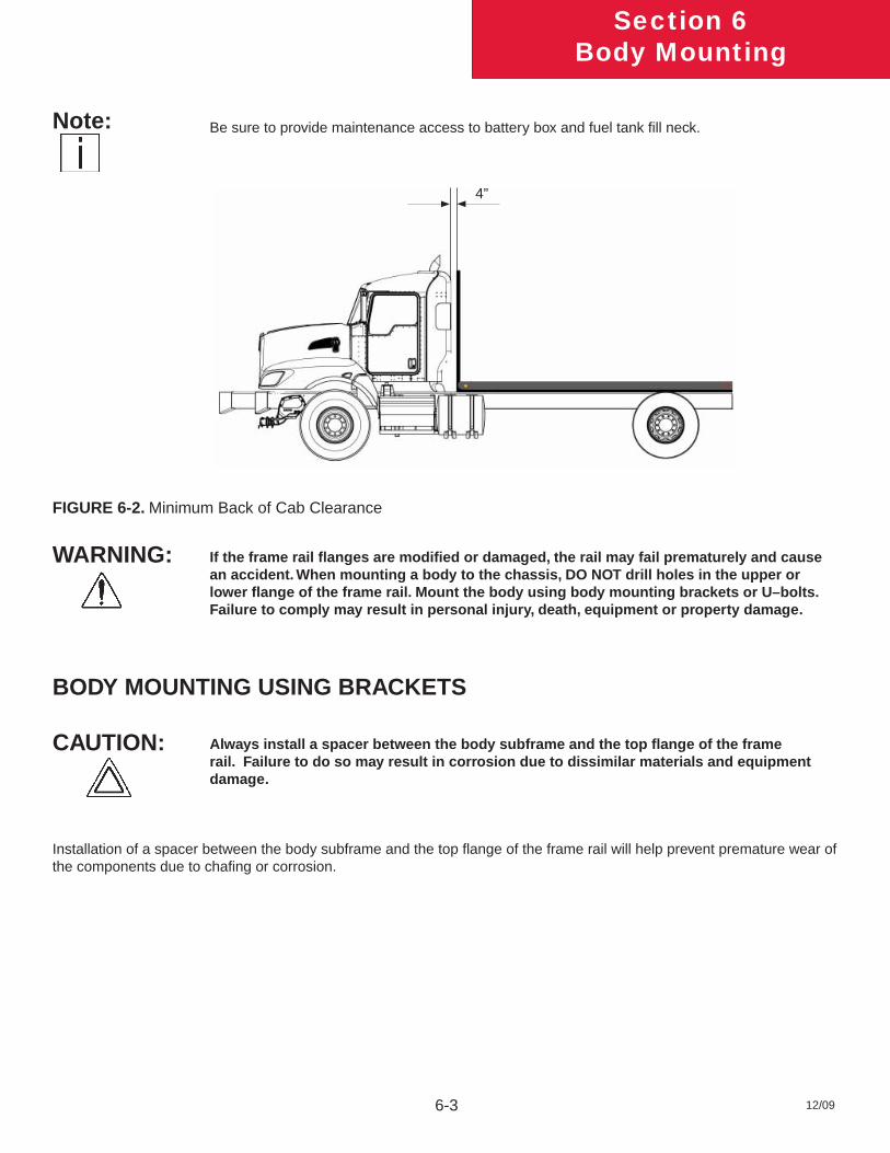
6-3 12/09
Section 6Body Mounting
Be sure to provide maintenance access to battery box and fuel tank fi ll neck.
FIGURE 6-2. Minimum Back of Cab Clearance
If the frame rail fl anges are modifi ed or damaged, the rail may fail prematurely and cause an accident. When mounting a body to the chassis, DO NOT drill holes in the upper or lower fl ange of the frame rail. Mount the body using body mounting brackets or U–bolts. Failure to comply may result in personal injury, death, equipment or property damage.
BODY MOUNTING USING BRACKETS
Always install a spacer between the body subframe and the top fl ange of the frame rail. Failure to do so may result in corrosion due to dissimilar materials and equipment damage.
Installation of a spacer between the body subframe and the top fl ange of the frame rail will help prevent premature wear of the components due to chafi ng or corrosion.
WARNING:
CAUTION:
4”
Note:
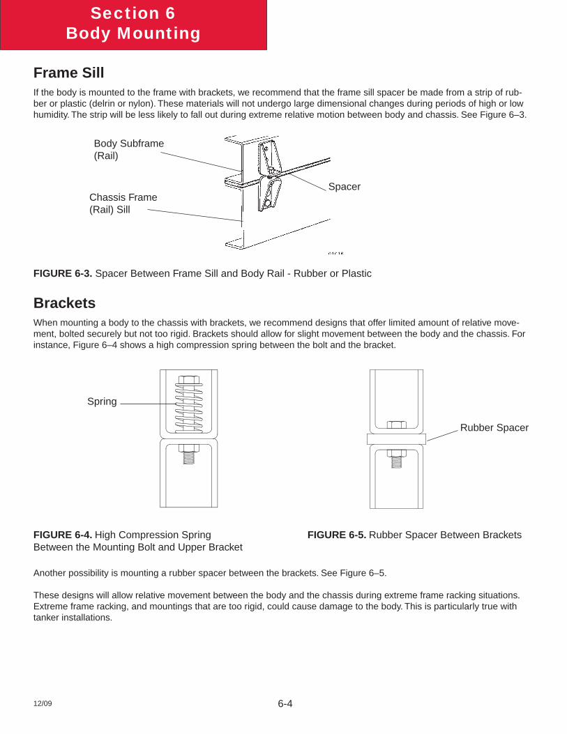
6-412/09
Section 6Body Mounting
Frame SillIf the body is mounted to the frame with brackets, we recommend that the frame sill spacer be made from a strip of rub-ber or plastic (delrin or nylon). These materials will not undergo large dimensional changes during periods of high or low humidity. The strip will be less likely to fall out during extreme relative motion between body and chassis. See Figure 6–3.
FIGURE 6-3. Spacer Between Frame Sill and Body Rail - Rubber or Plastic
BracketsWhen mounting a body to the chassis with brackets, we recommend designs that offer limited amount of relative move-ment, bolted securely but not too rigid. Brackets should allow for slight movement between the body and the chassis. For instance, Figure 6–4 shows a high compression spring between the bolt and the bracket.
FIGURE 6-4. High Compression Spring FIGURE 6-5. Rubber Spacer Between BracketsBetween the Mounting Bolt and Upper Bracket
Another possibility is mounting a rubber spacer between the brackets. See Figure 6–5.
These designs will allow relative movement between the body and the chassis during extreme frame racking situations. Extreme frame racking, and mountings that are too rigid, could cause damage to the body. This is particularly true with tanker installations.
Body Subframe (Rail)
Chassis Frame (Rail) Sill
Spacer
Spring
Rubber Spacer
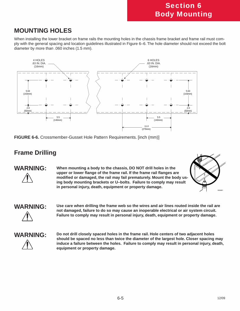
6-5 12/09
Section 6Body Mounting
MOUNTING HOLESWhen installing the lower bracket on frame rails the mounting holes in the chassis frame bracket and frame rail must com-ply with the general spacing and location guidelines illustrated in Figure 6–6. The hole diameter should not exceed the bolt diameter by more than .060 inches (1.5 mm).
4 HOLES.5 IN. DIA.(12.7mm)
5.5(140mm)
2.0(50mm)
5.63(143mm)
5.5(140mm)
2.0(50mm)
5.63(143mm)
11.0(279mm)
6 HOLES.5 IN. DIA.(12.7mm)
FIGURE 6-6. Crossmember-Gusset Hole Pattern Requirements. [inch (mm)]
Frame Drilling
When mounting a body to the chassis, DO NOT drill holes in the upper or lower fl ange of the frame rail. If the frame rail fl anges are modifi ed or damaged, the rail may fail prematurely. Mount the body us-ing body mounting brackets or U–bolts. Failure to comply may result in personal injury, death, equipment or property damage.
Use care when drilling the frame web so the wires and air lines routed inside the rail are not damaged, failure to do so may cause an inoperable electrical or air system circuit. Failure to comply may result in personal injury, death, equipment or property damage.
Do not drill closely spaced holes in the frame rail. Hole centers of two adjacent holes should be spaced no less than twice the diameter of the largest hole. Closer spacing may induce a failure between the holes. Failure to comply may result in personal injury, death, equipment or property damage.
WARNING:
WARNING:
WARNING:
4 HOLES.63 IN. DIA.
(16mm)
6 HOLES.63 IN. DIA.
(16mm)
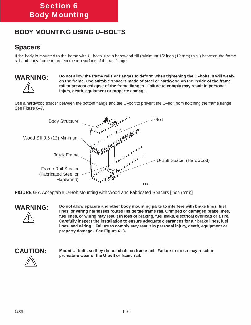
6-612/09
Section 6Body Mounting
BODY MOUNTING USING U–BOLTS
SpacersIf the body is mounted to the frame with U–bolts, use a hardwood sill (minimum 1/2 inch (12 mm) thick) between the frame rail and body frame to protect the top surface of the rail fl ange.
Do not allow the frame rails or fl anges to deform when tightening the U–bolts. It will weak-en the frame. Use suitable spacers made of steel or hardwood on the inside of the frame rail to prevent collapse of the frame fl anges. Failure to comply may result in personal injury, death, equipment or property damage.
Use a hardwood spacer between the bottom fl ange and the U–bolt to prevent the U–bolt from notching the frame fl ange. See Figure 6–7.
Body Structure
Wood Sill 0.5 (12) Minimum
Truck Frame
Frame Rail Spacer (Fabricated Steel or
Hardwood)
U-Bolt Spacer (Hardwood)
U-Bolt
FIGURE 6-7. Acceptable U-Bolt Mounting with Wood and Fabricated Spacers [inch (mm)]
Do not allow spacers and other body mounting parts to interfere with brake lines, fuel lines, or wiring harnesses routed inside the frame rail. Crimped or damaged brake lines, fuel lines, or wiring may result in loss of braking, fuel leaks, electrical overload or a fi re. Carefully inspect the installation to ensure adequate clearances for air brake lines, fuel lines, and wiring. Failure to comply may result in personal injury, death, equipment or property damage. See Figure 6–8.
Mount U–bolts so they do not chafe on frame rail. Failure to do so may result in premature wear of the U-bolt or frame rail.
WARNING:
CAUTION:
WARNING:
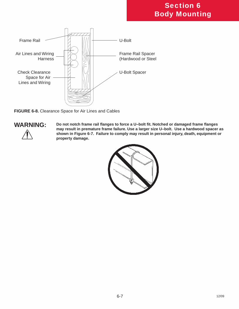
6-7 12/09
Section 6Body Mounting
FIGURE 6-8. Clearance Space for Air Lines and Cables
Do not notch frame rail fl anges to force a U–bolt fi t. Notched or damaged frame fl anges may result in premature frame failure. Use a larger size U–bolt. Use a hardwood spacer as shown in Figure 6-7. Failure to comply may result in personal injury, death, equipment or property damage.
Frame Rail
Air Lines and Wiring Harness
Check Clearance Space for Air
Lines and Wiring
U-Bolt
Frame Rail Spacer (Hardwood or Steel
U-Bolt Spacer
WARNING:
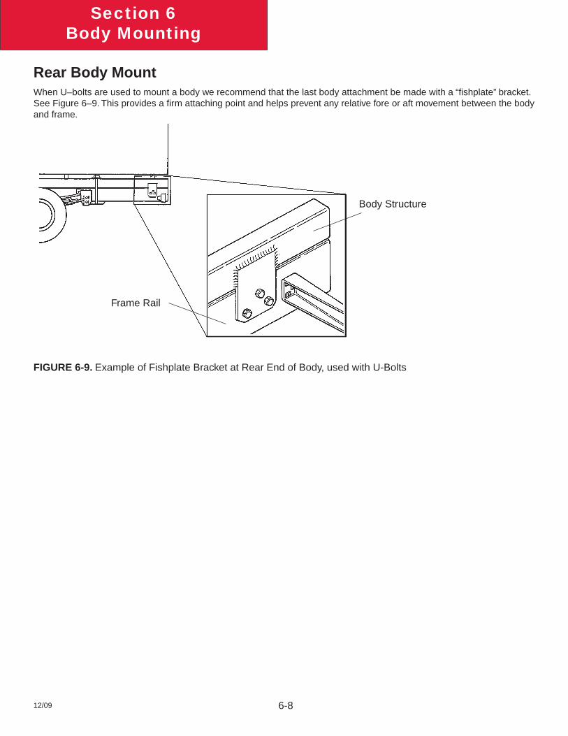
6-812/09
Section 6Body Mounting
Rear Body MountWhen U–bolts are used to mount a body we recommend that the last body attachment be made with a “fi shplate” bracket. See Figure 6–9. This provides a fi rm attaching point and helps prevent any relative fore or aft movement between the body and frame.
FIGURE 6-9. Example of Fishplate Bracket at Rear End of Body, used with U-Bolts
Body Structure
Frame Rail
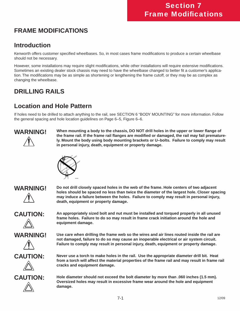
12/09
Section 7Frame Modifi cations
7-1
FRAME MODIFICATIONS
IntroductionKenworth offers customer specifi ed wheelbases. So, in most cases frame modifi cations to produce a certain wheelbase should not be necessary.
However, some installations may require slight modifi cations, while other installations will require extensive modifi cations. Sometimes an existing dealer stock chassis may need to have the wheelbase changed to better fi t a customer’s applica-tion. The modifi cations may be as simple as shortening or lengthening the frame cutoff, or they may be as complex as changing the wheelbase.
DRILLING RAILS
Location and Hole PatternIf holes need to be drilled to attach anything to the rail, see SECTION 6 “BODY MOUNTING” for more information. Follow the general spacing and hole location guidelines on Page 6–5, Figure 6–6.
When mounting a body to the chassis, DO NOT drill holes in the upper or lower fl ange of the frame rail. If the frame rail fl anges are modifi ed or damaged, the rail may fail premature-ly. Mount the body using body mounting brackets or U–bolts. Failure to comply may result in personal injury, death, equipment or property damage.
Do not drill closely spaced holes in the web of the frame. Hole centers of two adjacent holes should be spaced no less than twice the diameter of the largest hole. Closer spacing may induce a failure between the holes. Failure to comply may result in personal injury, death, equipment or property damage.
An appropriately sized bolt and nut must be installed and torqued properly in all unused frame holes. Failure to do so may result in frame crack initiation around the hole and equipment damage.
Use care when drilling the frame web so the wires and air lines routed inside the rail are not damaged, failure to do so may cause an inoperable electrical or air system circuit. Failure to comply may result in personal injury, death, equipment or property damage.
Never use a torch to make holes in the rail. Use the appropriate diameter drill bit. Heat from a torch will affect the material properties of the frame rail and may result in frame rail cracks and equipment damage.
Hole diameter should not exceed the bolt diameter by more than .060 inches (1.5 mm). Oversized holes may result in excessive frame wear around the hole and equipment damage.
WARNING!
CAUTION:
WARNING!
CAUTION:
CAUTION:
WARNING!
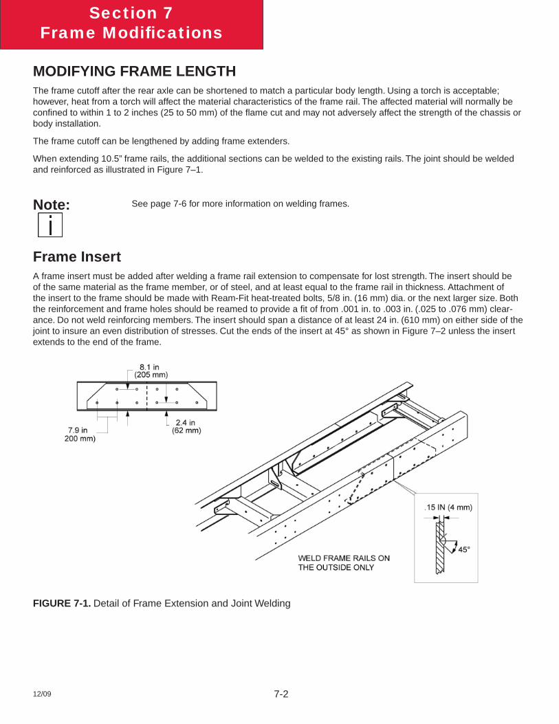
12/09
Section 7Frame Modifi cations
7-2
MODIFYING FRAME LENGTHThe frame cutoff after the rear axle can be shortened to match a particular body length. Using a torch is acceptable; however, heat from a torch will affect the material characteristics of the frame rail. The affected material will normally be confi ned to within 1 to 2 inches (25 to 50 mm) of the fl ame cut and may not adversely affect the strength of the chassis or body installation.
The frame cutoff can be lengthened by adding frame extenders.
When extending 10.5” frame rails, the additional sections can be welded to the existing rails. The joint should be welded and reinforced as illustrated in Figure 7–1.
See page 7-6 for more information on welding frames.
Frame InsertA frame insert must be added after welding a frame rail extension to compensate for lost strength. The insert should be of the same material as the frame member, or of steel, and at least equal to the frame rail in thickness. Attachment of the insert to the frame should be made with Ream-Fit heat-treated bolts, 5/8 in. (16 mm) dia. or the next larger size. Both the reinforcement and frame holes should be reamed to provide a fi t of from .001 in. to .003 in. (.025 to .076 mm) clear-ance. Do not weld reinforcing members. The insert should span a distance of at least 24 in. (610 mm) on either side of the joint to insure an even distribution of stresses. Cut the ends of the insert at 45° as shown in Figure 7–2 unless the insert extends to the end of the frame.
FIGURE 7-1. Detail of Frame Extension and Joint Welding
Note:
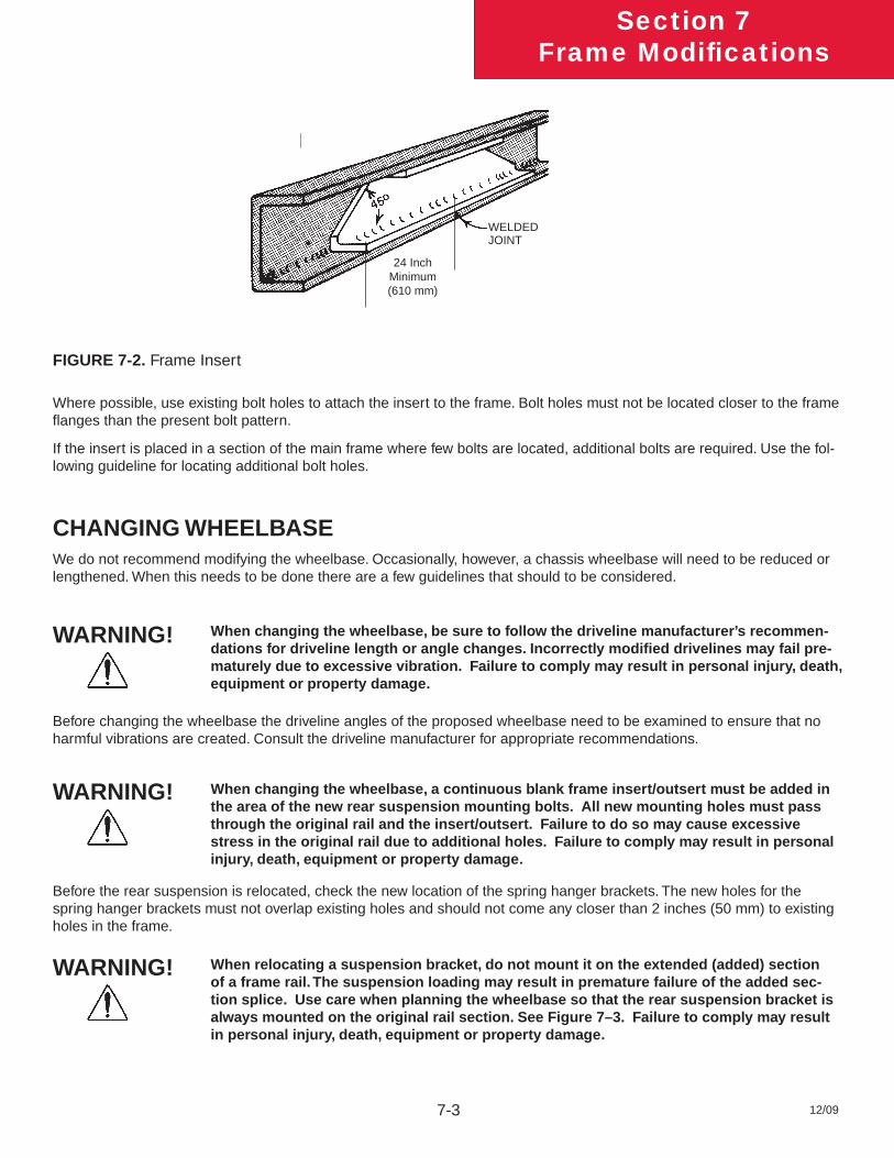
12/09
Section 7Frame Modifi cations
7-3
FIGURE 7-2. Frame Insert
Where possible, use existing bolt holes to attach the insert to the frame. Bolt holes must not be located closer to the frame fl anges than the present bolt pattern.
If the insert is placed in a section of the main frame where few bolts are located, additional bolts are required. Use the fol-lowing guideline for locating additional bolt holes.
CHANGING WHEELBASEWe do not recommend modifying the wheelbase. Occasionally, however, a chassis wheelbase will need to be reduced or lengthened. When this needs to be done there are a few guidelines that should to be considered.
When changing the wheelbase, be sure to follow the driveline manufacturer’s recommen-dations for driveline length or angle changes. Incorrectly modifi ed drivelines may fail pre-maturely due to excessive vibration. Failure to comply may result in personal injury, death, equipment or property damage.
When changing the wheelbase, a continuous blank frame insert/outsert must be added in the area of the new rear suspension mounting bolts. All new mounting holes must pass through the original rail and the insert/outsert. Failure to do so may cause excessive stress in the original rail due to additional holes. Failure to comply may result in personal injury, death, equipment or property damage.
When relocating a suspension bracket, do not mount it on the extended (added) section of a frame rail. The suspension loading may result in premature failure of the added sec-tion splice. Use care when planning the wheelbase so that the rear suspension bracket is always mounted on the original rail section. See Figure 7–3. Failure to comply may result in personal injury, death, equipment or property damage.
24 Inch Minimum(610 mm)
WARNING!
WARNING!
WARNING!
WELDED JOINT
Before changing the wheelbase the driveline angles of the proposed wheelbase need to be examined to ensure that no harmful vibrations are created. Consult the driveline manufacturer for appropriate recommendations.
Before the rear suspension is relocated, check the new location of the spring hanger brackets. The new holes for the spring hanger brackets must not overlap existing holes and should not come any closer than 2 inches (50 mm) to existing holes in the frame.
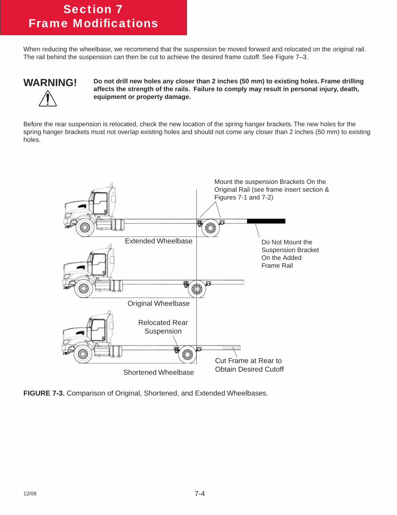
12/09
Section 7Frame Modifi cations
7-4
When reducing the wheelbase, we recommend that the suspension be moved forward and relocated on the original rail. The rail behind the suspension can then be cut to achieve the desired frame cutoff. See Figure 7–3.
Do not drill new holes any closer than 2 inches (50 mm) to existing holes. Frame drilling affects the strength of the rails. Failure to comply may result in personal injury, death, equipment or property damage.
Before the rear suspension is relocated, check the new location of the spring hanger brackets. The new holes for the spring hanger brackets must not overlap existing holes and should not come any closer than 2 inches (50 mm) to existing holes.
FIGURE 7-3. Comparison of Original, Shortened, and Extended Wheelbases.
WARNING!
Original Wheelbase
Extended Wheelbase
Shortened Wheelbase
Cut Frame at Rear to Obtain Desired Cutoff
Do Not Mount the Suspension Bracket On the Added Frame Rail
Mount the suspension Brackets On the Original Rail (see frame insert section & Figures 7-1 and 7-2)
Relocated Rear Suspension
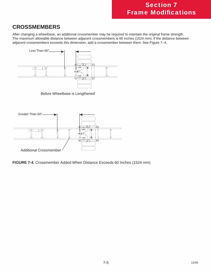
12/09
Section 7Frame Modifi cations
7-5
CROSSMEMBERSAfter changing a wheelbase, an additional crossmember may be required to maintain the original frame strength. The maximum allowable distance between adjacent crossmembers is 60 inches (1524 mm). If the distance between adjacent crossmembers exceeds this dimension, add a crossmember between them. See Figure 7–4.
Before Wheelbase is Lengthened
Less Than 60”
Greater Than 60”
Additional Crossmember
FIGURE 7-4. Crossmember Added When Distance Exceeds 60 Inches (1524 mm)
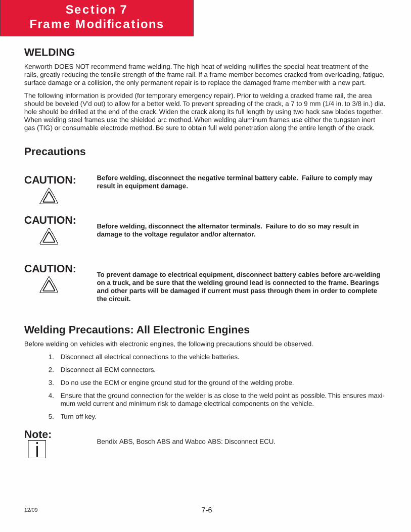
12/09
Section 7Frame Modifi cations
7-6
WELDINGKenworth DOES NOT recommend frame welding. The high heat of welding nullifi es the special heat treatment of the rails, greatly reducing the tensile strength of the frame rail. If a frame member becomes cracked from overloading, fatigue, surface damage or a collision, the only permanent repair is to replace the damaged frame member with a new part.
The following information is provided (for temporary emergency repair). Prior to welding a cracked frame rail, the area should be beveled (V’d out) to allow for a better weld. To prevent spreading of the crack, a 7 to 9 mm (1/4 in. to 3/8 in.) dia. hole should be drilled at the end of the crack. Widen the crack along its full length by using two hack saw blades together. When welding steel frames use the shielded arc method. When welding aluminum frames use either the tungsten inert gas (TIG) or consumable electrode method. Be sure to obtain full weld penetration along the entire length of the crack.
Precautions
Before welding, disconnect the negative terminal battery cable. Failure to comply may result in equipment damage.
Before welding, disconnect the alternator terminals. Failure to do so may result in damage to the voltage regulator and/or alternator.
To prevent damage to electrical equipment, disconnect battery cables before arc-welding on a truck, and be sure that the welding ground lead is connected to the frame. Bearings and other parts will be damaged if current must pass through them in order to complete the circuit.
Welding Precautions: All Electronic EnginesBefore welding on vehicles with electronic engines, the following precautions should be observed.
1. Disconnect all electrical connections to the vehicle batteries.
2. Disconnect all ECM connectors.
3. Do no use the ECM or engine ground stud for the ground of the welding probe.
4. Ensure that the ground connection for the welder is as close to the weld point as possible. This ensures maxi-mum weld current and minimum risk to damage electrical components on the vehicle.
5. Turn off key.
Bendix ABS, Bosch ABS and Wabco ABS: Disconnect ECU.
CAUTION:
CAUTION:
CAUTION:
Note:
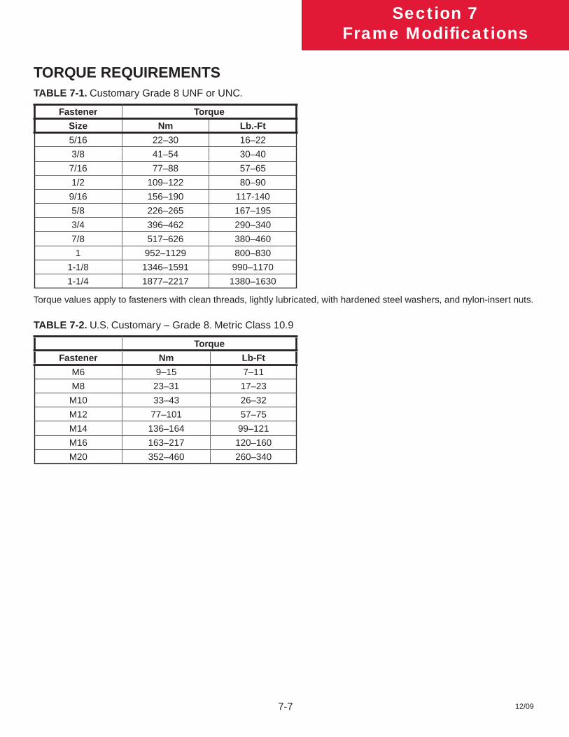
12/09
Section 7Frame Modifi cations
7-7
TORQUE REQUIREMENTSTABLE 7-1. Customary Grade 8 UNF or UNC.
Fastener Torque
Size Nm Lb.-Ft
5/16 22–30 16–22
3/8 41–54 30–40
7/16 77–88 57–65
1/2 109–122 80–90
9/16 156–190 117-140
5/8 226–265 167–195
3/4 396–462 290–340
7/8 517–626 380–460
1 952–1129 800–830
1-1/8 1346–1591 990–1170
1-1/4 1877–2217 1380–1630
Torque values apply to fasteners with clean threads, lightly lubricated, with hardened steel washers, and nylon-insert nuts.
TABLE 7-2. U.S. Customary – Grade 8. Metric Class 10.9
Torque
Fastener Nm Lb-Ft
M6 9–15 7–11
M8 23–31 17–23
M10 33–43 26–32
M12 77–101 57–75
M14 136–164 99–121
M16 163–217 120–160
M20 352–460 260–340

This page intentionally left blank.
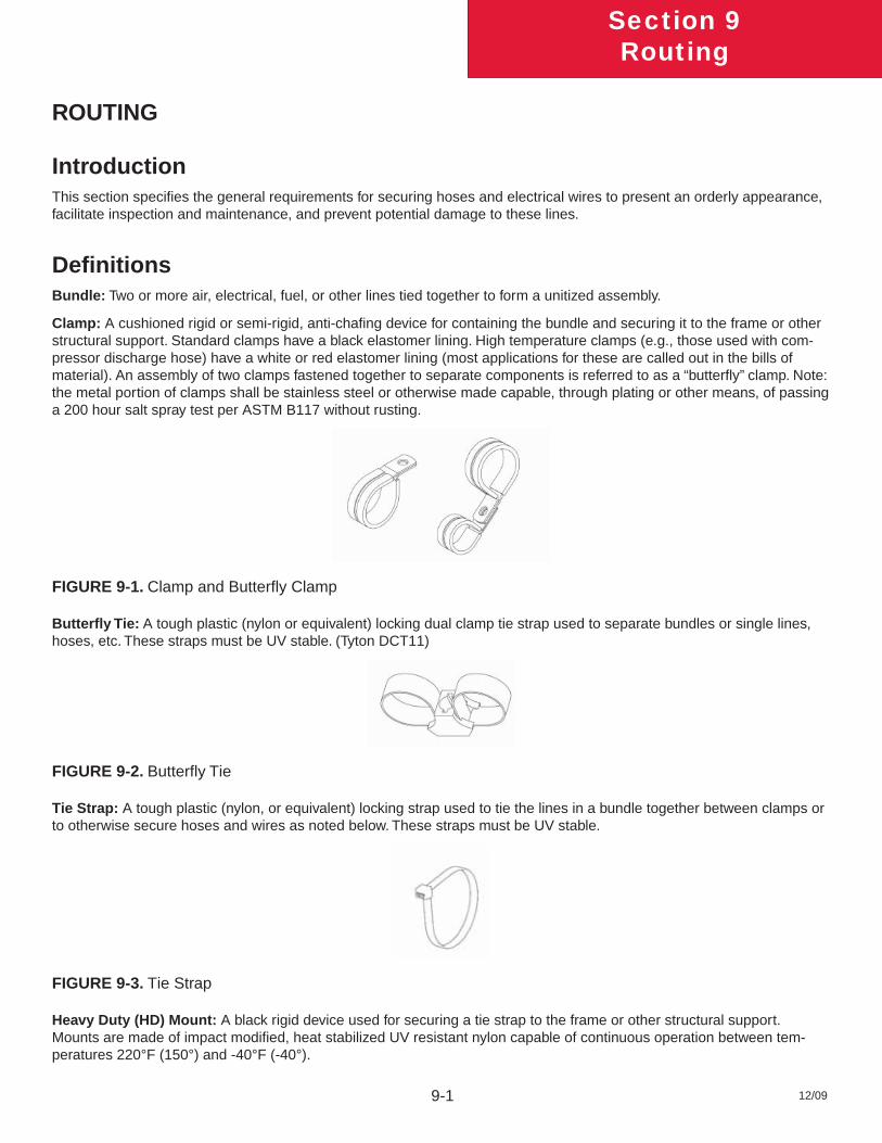
12/09
Section 9Routing
9-1
ROUTING
IntroductionThis section specifi es the general requirements for securing hoses and electrical wires to present an orderly appearance, facilitate inspection and maintenance, and prevent potential damage to these lines.
Defi nitionsBundle: Two or more air, electrical, fuel, or other lines tied together to form a unitized assembly.
Clamp: A cushioned rigid or semi-rigid, anti-chafi ng device for containing the bundle and securing it to the frame or other structural support. Standard clamps have a black elastomer lining. High temperature clamps (e.g., those used with com-pressor discharge hose) have a white or red elastomer lining (most applications for these are called out in the bills of material). An assembly of two clamps fastened together to separate components is referred to as a “butterfl y” clamp. Note: the metal portion of clamps shall be stainless steel or otherwise made capable, through plating or other means, of passing a 200 hour salt spray test per ASTM B117 without rusting.
FIGURE 9-1. Clamp and Butterfl y Clamp
Butterfl y Tie: A tough plastic (nylon or equivalent) locking dual clamp tie strap used to separate bundles or single lines, hoses, etc. These straps must be UV stable. (Tyton DCT11)
FIGURE 9-2. Butterfl y Tie
Tie Strap: A tough plastic (nylon, or equivalent) locking strap used to tie the lines in a bundle together between clamps or to otherwise secure hoses and wires as noted below. These straps must be UV stable.
FIGURE 9-3. Tie Strap
Heavy Duty (HD) Mount: A black rigid device used for securing a tie strap to the frame or other structural support. Mounts are made of impact modifi ed, heat stabilized UV resistant nylon capable of continuous operation between tem-peratures 220°F (150°) and -40°F (-40°).
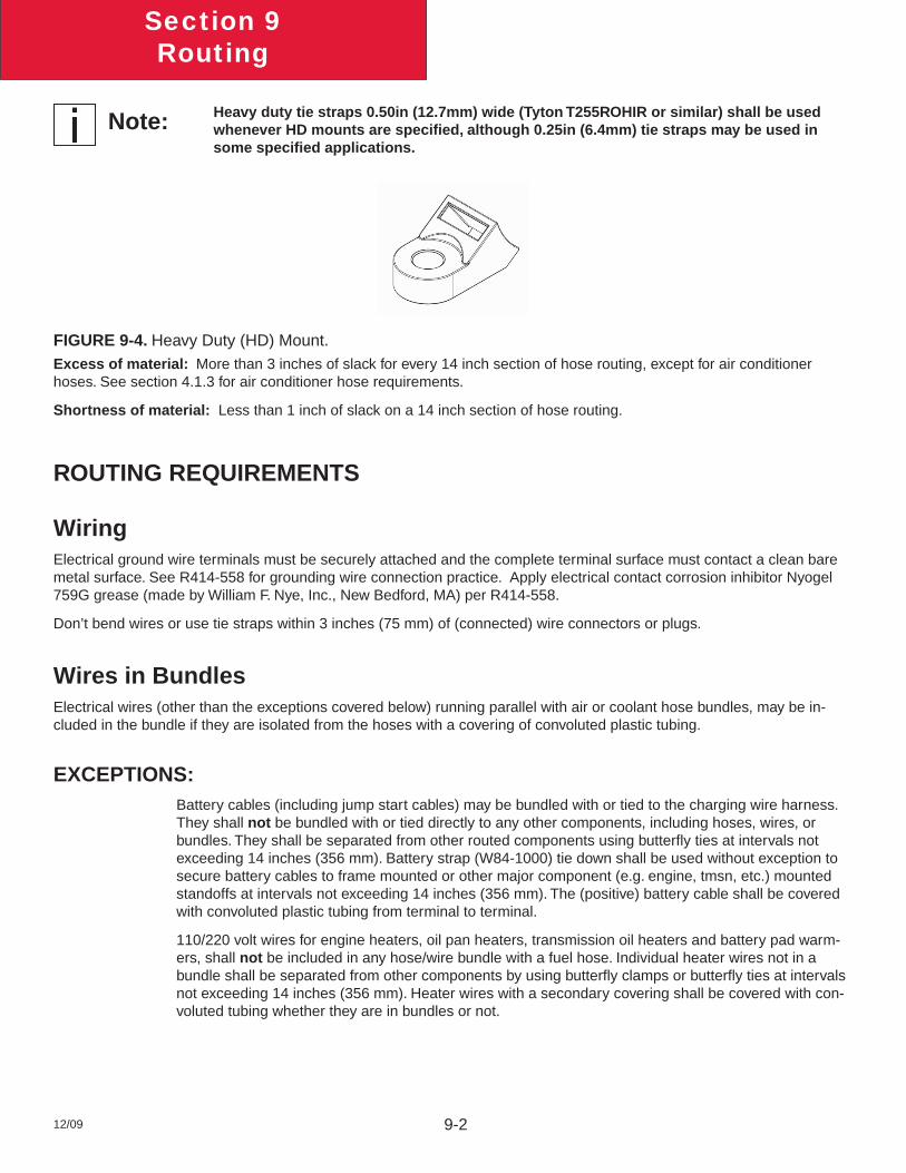
12/09
Section 9Routing
9-2
Heavy duty tie straps 0.50in (12.7mm) wide (Tyton T255ROHIR or similar) shall be used whenever HD mounts are specifi ed, although 0.25in (6.4mm) tie straps may be used in some specifi ed applications.
FIGURE 9-4. Heavy Duty (HD) Mount.Excess of material: More than 3 inches of slack for every 14 inch section of hose routing, except for air conditioner hoses. See section 4.1.3 for air conditioner hose requirements.
Shortness of material: Less than 1 inch of slack on a 14 inch section of hose routing.
ROUTING REQUIREMENTS
Wiring Electrical ground wire terminals must be securely attached and the complete terminal surface must contact a clean bare metal surface. See R414-558 for grounding wire connection practice. Apply electrical contact corrosion inhibitor Nyogel 759G grease (made by William F. Nye, Inc., New Bedford, MA) per R414-558.
Don’t bend wires or use tie straps within 3 inches (75 mm) of (connected) wire connectors or plugs.
Wires in BundlesElectrical wires (other than the exceptions covered below) running parallel with air or coolant hose bundles, may be in-cluded in the bundle if they are isolated from the hoses with a covering of convoluted plastic tubing.
EXCEPTIONS:Battery cables (including jump start cables) may be bundled with or tied to the charging wire harness. They shall not be bundled with or tied directly to any other components, including hoses, wires, or bundles. They shall be separated from other routed components using butterfl y ties at intervals not exceeding 14 inches (356 mm). Battery strap (W84-1000) tie down shall be used without exception to secure battery cables to frame mounted or other major component (e.g. engine, tmsn, etc.) mounted standoffs at intervals not exceeding 14 inches (356 mm). The (positive) battery cable shall be covered with convoluted plastic tubing from terminal to terminal.
110/220 volt wires for engine heaters, oil pan heaters, transmission oil heaters and battery pad warm-ers, shall not be included in any hose/wire bundle with a fuel hose. Individual heater wires not in a bundle shall be separated from other components by using butterfl y clamps or butterfl y ties at intervals not exceeding 14 inches (356 mm). Heater wires with a secondary covering shall be covered with con-voluted tubing whether they are in bundles or not.
Note:
12/09
Section 9Routing
9-3
Wires Crossing other ComponentsElectrical wires crossing over other components, such as lines, bolt heads, fi ttings, engine components lifting eyes, engine block, cylinder head, etc., close enough to rub shall be isolated with a covering of convoluted tubing and separated from the component by using butterfl y clamps, butterfl y ties, or plastic sheathing. 110/220 volt engine heater wiring shall be installed with butterfl y ties or butterfl y clamps
Piping Use no street elbows in air brake, water, fuel, or hydraulic systems unless specifi ed on the piping diagram and the build instructions.
Use no elbows in the air brake system unless specifi ed on the air piping diagram and the build instructions.
Hoses Crossing ComponentsHoses crossing over other components close enough to rub shall be protected with a secured covering of convoluted plas-tic tubing (KW part number K344-813), another section of hose, or plastic sheathing (KW part number K213-1312). The usage of butterfl y ties, or butterfl y clamps are also recommended.
Air Compressor Discharge HosesWires or hoses shall not be tied to the high temperature air compressor discharge hose. Hoses and wires may be routed across the air compressor discharge hose at a distance of 18 inches (457 mm) or greater from the compressor discharge port. In this case the crossing hoses and wires shall be “butterfl y” clamped to the air compressor discharge hose and cov-ered with convoluted tubing at the clamp point (use high temperature clamps on the compressor hose).
BundlesHD mount and tie strap, or clamp shall be located at intervals not to exceed 14 inches (356 mm) along the bundle.
Regular tie straps shall be located at intervals not to exceed 7 inches (178 mm) between HD mount or clamps. Extra tie straps may be used as needed to contain the hoses and wires in the bundle.
Routing of Wires and Hoses near Moving ComponentsWires and Hoses shall be routed away from moving components, such as fans, shackle links, drivelines, steering linkages, etc. so that there is at least 0.5 inches (12.7 mm) clearance when the component is operating at its maximum travel limits.
A minimum clearance of 1.0 inchs (25.4) shall be maintained between steering axle tires (and associated rotating parts) in all positions and routed components, such as hoses, oil lines, wires, pipes, etc.
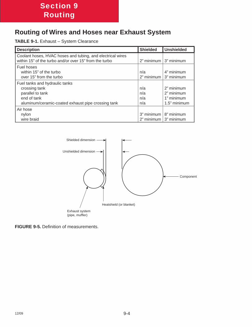
12/09
Section 9Routing
9-4
Routing of Wires and Hoses near Exhaust SystemTABLE 9-1. Exhaust – System Clearance
Description Shielded Unshielded
Coolant hoses, HVAC hoses and tubing, and electrical wires within 15” of the turbo and/or over 15” from the turbo 2” minimum 3” minimum
Fuel hoses within 15” of the turbo over 15” from the turbo
n/a2” minimum
4” minimum3” minimum
Fuel tanks and hydraulic tanks crossing tank parallel to tank end of tank aluminum/ceramic-coated exhaust pipe crossing tank
n/an/an/an/a
2” minimum2” minimum1” minimum1.5” minimum
Air hose nylon wire braid
3” minimum2” minimum
8” minimum3” minimum
Exhaust system(pipe, muffl er)
Heatshield (or blanket)
Component
Shielded dimension
Unshielded dimension
FIGURE 9-5. Defi nition of measurements.
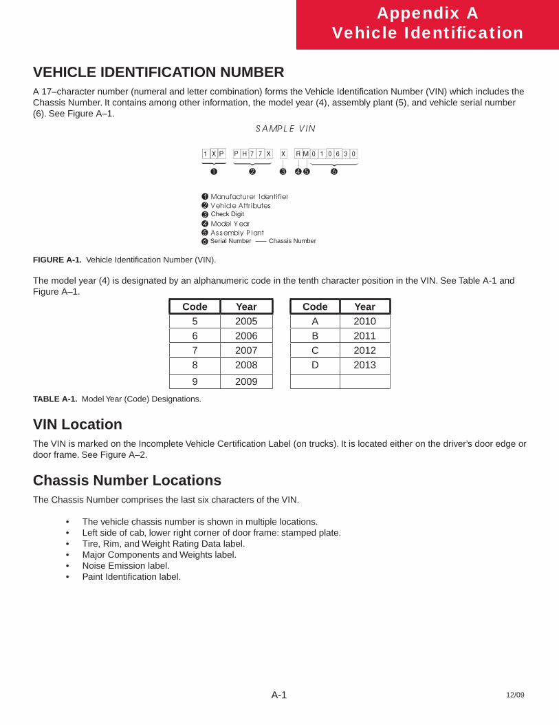
12/09
Appendix AVehicle Identifi cation
A-1
VEHICLE IDENTIFICATION NUMBER A 17–character number (numeral and letter combination) forms the Vehicle Identifi cation Number (VIN) which includes the Chassis Number. It contains among other information, the model year (4), assembly plant (5), and vehicle serial number (6). See Figure A–1.
M
Serial Number Chassis Number
FIGURE A-1. Vehicle Identifi cation Number (VIN).
The model year (4) is designated by an alphanumeric code in the tenth character position in the VIN. See Table A-1 and Figure A–1.
Code Year Code Year5 2005 A 20106 2006 B 20117 2007 C 20128 2008 D 2013
9 2009
TABLE A-1. Model Year (Code) Designations.
VIN LocationThe VIN is marked on the Incomplete Vehicle Certifi cation Label (on trucks). It is located either on the driver’s door edge or door frame. See Figure A–2.
Chassis Number LocationsThe Chassis Number comprises the last six characters of the VIN.
The vehicle chassis number is shown in multiple locations.• Left side of cab, lower right corner of door frame: stamped plate.• Tire, Rim, and Weight Rating Data label.• Major Components and Weights label.• Noise Emission label.• Paint Identifi cation label.•
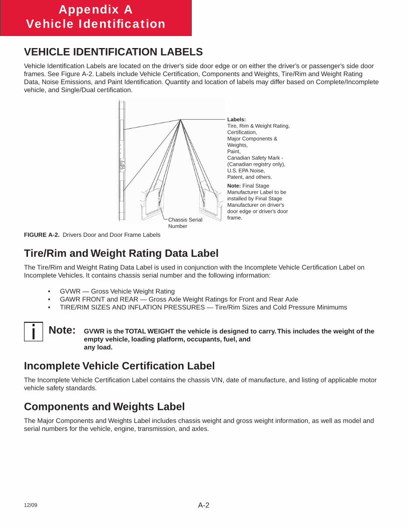
12/09
Appendix AVehicle Identifi cation
A-2
Note:
VEHICLE IDENTIFICATION LABELSVehicle Identifi cation Labels are located on the driver’s side door edge or on either the driver’s or passenger’s side door frames. See Figure A-2. Labels include Vehicle Certifi cation, Components and Weights, Tire/Rim and Weight Rating Data, Noise Emissions, and Paint Identifi cation. Quantity and location of labels may differ based on Complete/Incomplete vehicle, and Single/Dual certifi cation.
Labels:Tire, Rim & Weight Rating,Certifi cation, Major Components & Weights, Paint, Canadian Safety Mark - (Canadian registry only), U.S. EPA Noise, Patent, and others.
Note: Final Stage Manufacturer Label to be installed by Final Stage Manufacturer on driver’s door edge or driver’s door frame.Chassis Serial
Number
FIGURE A-2. Drivers Door and Door Frame Labels
Tire/Rim and Weight Rating Data LabelThe Tire/Rim and Weight Rating Data Label is used in conjunction with the Incomplete Vehicle Certifi cation Label on Incomplete Vehicles. It contains chassis serial number and the following information:
GVWR — Gross Vehicle Weight Rating• GAWR FRONT and REAR — Gross Axle Weight Ratings for Front and Rear Axle• TIRE/RIM SIZES AND INFLATION PRESSURES — Tire/Rim Sizes and Cold Pressure Minimums•
GVWR is the TOTAL WEIGHT the vehicle is designed to carry. This includes the weight of the empty vehicle, loading platform, occupants, fuel, and any load.
Incomplete Vehicle Certifi cation LabelThe Incomplete Vehicle Certifi cation Label contains the chassis VIN, date of manufacture, and listing of applicable motor vehicle safety standards.
Components and Weights LabelThe Major Components and Weights Label includes chassis weight and gross weight information, as well as model and serial numbers for the vehicle, engine, transmission, and axles.
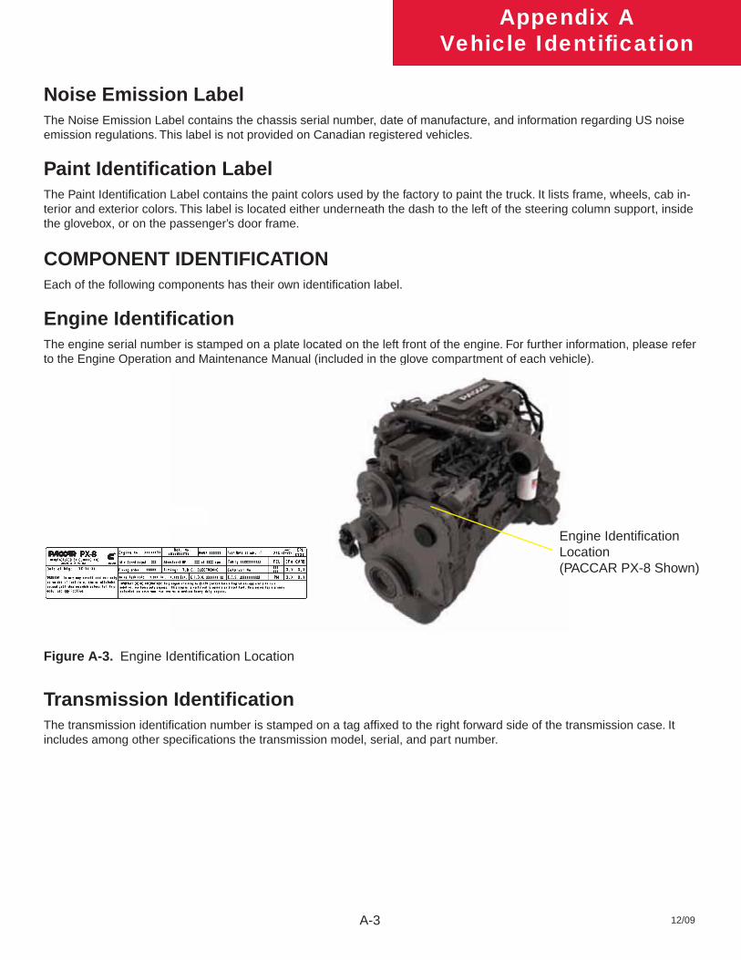
12/09
Appendix AVehicle Identifi cation
A-3
Noise Emission LabelThe Noise Emission Label contains the chassis serial number, date of manufacture, and information regarding US noise emission regulations. This label is not provided on Canadian registered vehicles.
Paint Identifi cation LabelThe Paint Identifi cation Label contains the paint colors used by the factory to paint the truck. It lists frame, wheels, cab in-terior and exterior colors. This label is located either underneath the dash to the left of the steering column support, inside the glovebox, or on the passenger’s door frame.
COMPONENT IDENTIFICATIONEach of the following components has their own identifi cation label.
Engine Identifi cationThe engine serial number is stamped on a plate located on the left front of the engine. For further information, please refer to the Engine Operation and Maintenance Manual (included in the glove compartment of each vehicle).
Figure A-3. Engine Identifi cation Location
Transmission Identifi cationThe transmission identifi cation number is stamped on a tag affi xed to the right forward side of the transmission case. It includes among other specifi cations the transmission model, serial, and part number.
Engine Identifi cation Location(PACCAR PX-8 Shown)
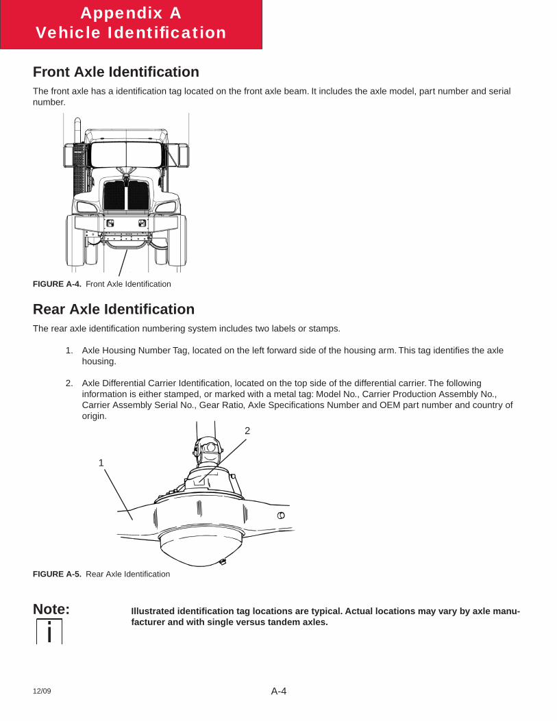
12/09
Appendix AVehicle Identifi cation
A-4
Note:
Front Axle Identifi cationThe front axle has a identifi cation tag located on the front axle beam. It includes the axle model, part number and serial number.
FIGURE A-4. Front Axle Identifi cation
Rear Axle Identifi cationThe rear axle identifi cation numbering system includes two labels or stamps.
Axle Housing Number Tag, located on the left forward side of the housing arm. This tag identifi es the axle 1. housing.
Axle Differential Carrier Identifi cation, located on the top side of the differential carrier. The following 2. information is either stamped, or marked with a metal tag: Model No., Carrier Production Assembly No., Carrier Assembly Serial No., Gear Ratio, Axle Specifi cations Number and OEM part number and country of origin.
1
2
FIGURE A-5. Rear Axle Identifi cation
Illustrated identifi cation tag locations are typical. Actual locations may vary by axle manu-facturer and with single versus tandem axles.

12/09
Appendix AVehicle Identifi cation
A-5
This page intentionally left blank.

12/09
Appendix AVehicle Identifi cation
A-6
Kenworth Truck CompanyP.O. Box 1000Kirkland, WA 98083(425) 828-5000
®