t440, t470 operator manual - pages · contents ©2012paccarinc-allrightsreserved...
TRANSCRIPT


Contents
Safety
Emergency
Controls
Driving
Maintenance
Information
Index
1
2
3
4
5
6
7
Contents
©2012 Paccar Inc - All Rights Reserved
This manual illustrates and describes the operation of features or equipment which may be either standard or optional onthis vehicle. This manual may also include a description of features and equipment which are no longer available or werenot ordered on this vehicle. Please disregard any illustrations or descriptions relating to features or equipment which arenot on this vehicle.
PACCAR reserves the right to discontinue, change specifications, or change the design of its vehicles at any time withoutnotice and without incurring any obligation.
The information contained in this manual is proprietary to Kenworth. Reproduction, in whole or in part, by any means isstrictly prohibited without prior written authorization from PACCAR Inc.
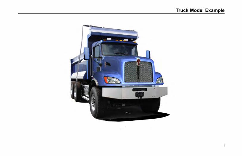
Truck Model Example
i

SAFETY
INTRODUCTIONAbout This Manual . . . . . . . . . . . . . . . 1-3Safety Alerts . . . . . . . . . . . . . . . . . . 1-3Vehicle Safety . . . . . . . . . . . . . . . . . 1-5Repairs . . . . . . . . . . . . . . . . . . . . 1-6Additional Sources of Information . . . . . . . . . 1-7California Proposition 65 Warning . . . . . . . . . 1-7Data Recorder . . . . . . . . . . . . . . . . . 1-8
SEATS AND RESTRAINTSIntroduction . . . . . . . . . . . . . . . . . . 1-9Safety Restraint Belts . . . . . . . . . . . . . 1-10Tether Belts . . . . . . . . . . . . . . . . . 1-14Komfort-Lok Feature . . . . . . . . . . . . . 1-16During Pregnancy. . . . . . . . . . . . . . . 1-17Belt Damage and Repair . . . . . . . . . . . . 1-17
START-UPIntroduction . . . . . . . . . . . . . . . . . 1-18
1-1
1
SAFETY
Door Lock and Keys . . . . . . . . . . . . . 1-18Remote Keyless Entry (Option) . . . . . . . . . 1-19Cab and Frame Access . . . . . . . . . . . . 1-21Hood Hold Downs. . . . . . . . . . . . . . . 1-23Hood Tilt . . . . . . . . . . . . . . . . . . 1-24Hood Safety Cable . . . . . . . . . . . . . . 1-24Safe Vehicle Operation . . . . . . . . . . . . 1-26Vehicle Loading. . . . . . . . . . . . . . . . 1-27Emergency Equipment . . . . . . . . . . . . 1-28Driver's Check List . . . . . . . . . . . . . . 1-28
1-2
1
INTRODUCTION
INTRODUCTION
About This Manual
Congratulations! Your selection of aKenworth truck was a wise investment.Kenworth trucks are recognized asthe industry standard for quality andreliability.
Please take the time to get acquaintedwith your vehicle by reading thisOperator’s Manual. We recommendthat you read and understand thismanual from beginning to end beforeyou operate your truck. This manualexplains the safe, efficient operationand maintenance of your Kenworth.
NOTE
After you’ve read this manual, itshould be stored in the cab forconvenient reference and remainwith this truck when sold.
Your Kenworth may not have all thefeatures or options mentioned in thismanual. Therefore, you should paycareful attention to the instructions thatpertain to just your vehicle. In addition,if your vehicle is equipped with specialequipment or options not discussed inthis manual, consult your dealer or themanufacturer of the equipment.
All information contained in thismanual is based on the latestproduction information available at thetime of publication. Kenworth TruckCompany reserves the right to makechanges at any time without notice.
Safety Alerts
Please read and follow all of thesafety alerts contained in this manual.They are there for your protectionand information. These alerts canhelp you avoid injury to yourself, yourpassengers, and help prevent costlydamage to the vehicle. Safety alertsare highlighted by safety alert symbolsand signal words such as "WARNING","CAUTION", or "NOTE". Please do notignore any of these alerts.
1-3
1

INTRODUCTION
WARNING
WARNING
The safety message following thissymbol and signal word provides awarning against operating procedureswhich could cause injury or even death.They could also cause equipment orproperty damage. The alert will identifythe hazard, how to avoid it, and theprobable consequence of not avoidingthe hazard.
Example:
WARNING
Do not carry additional fuelcontainers in your vehicle. Fuelcontainers, either full or empty,may leak, explode, and cause orfeed a fire. Do not carry extrafuel containers. Even empty onesare dangerous. Failure to complymay result in personal injury, death,equipment or property damage.
CAUTION
CAUTION
The safety alert following this symboland signal word provides a cautionagainst operating procedures whichcould cause equipment or propertydamage. The alert will identify thehazard, how to avoid it, and theprobable consequence of not avoidingthe hazard.
Example:
CAUTION
Continuing to operate your vehiclewith insufficient oil pressure willcause serious engine damage.Failure to comply may result inequipment or property damage.
1-4
1
INTRODUCTION
NOTE
NOTE
The alert following this symbol andsignal word provides importantinformation that is not safety relatedbut should be followed. The alertwill highlight things that may not beobvious and is useful to your efficientoperation of the vehicle.
Example:
NOTEPumping the accelerator will notassist in starting the engine.
Vehicle Safety
WARNING
Do not drink and drive. Yourreflexes, perceptions, and judgmentcan be affected by even a smallamount of alcohol. You could have aserious or even fatal accident, if youdrive after drinking. Please do notdrink and drive or ride with a driverwho has been drinking. Failureto comply may result in personalinjury, death, equipment or propertydamage.
WARNING
Do not text and drive. Your reactiontime, perceptions and judgment canbe affected while texting or usingany other form of mobile messagingwhile driving. Failure to complymay result in death, personal injury,equipment or property damage.
Make sure your Kenworth is in topworking condition before headingout on the road, it is the responsibledriver's duty to do so. Inspect thevehicle according to the Driver's CheckList beginning on page 1-28.
Every new Kenworth vehicle isdesigned to conform to all FederalMotor Vehicle Safety Standardsapplicable at the time of manufacture.Even with these safety features,continued safe and reliable operationdepends greatly upon regular vehiclemaintenance. Follow the maintenancerecommendations found in PreventiveMaintenance on page 5-7. This willhelp preserve your investment.
Keep in mind that even a wellmaintained vehicle must be operatedwithin the range of its mechanicalcapabilities and the limits of its loadratings. See the Tire and Rim WeightRatings label on the driver's door edge.
1-5
1
INTRODUCTION
This manual is not a training manual.It cannot tell you everything you needto know about driving your Kenworthvehicle. For that you need a goodtraining program or truck drivingschool. If you have not been trained,get the proper training before youdrive. Only qualified drivers shoulddrive this vehicle.
Repairs
WARNING
Do not attempt repair work withoutsufficient training, service manuals,and the proper tools. You couldbe injured, or you could make yourvehicle unsafe. Do only those tasksyou are fully qualified to do.
WARNING
Modifying your vehicle can makeit unsafe. Some modificationscan affect your vehicle's electricalsystem, stability, or other importantfunctions. Before modifying yourvehicle, check with your dealer tomake sure it can be done safely.
Your Kenworth vehicle is a complexmachine. Anyone attempting repairson it needs the appropriate mechanicaltraining, specifications, and tools.Your authorized Kenworth Dealeris the best place to have yourKenworth repaired and they arededicated to your satisfaction. Theirtechnicians are specially trained inservicing the many unique systemson your vehicle. To find a dealernear you, give us a call toll-FREE at1-800-KW-ASSIST (1-800-592-7747)24-7-365 days a year or visit usonline at www.kenworth.com andclick on the "dealers" link. When itcomes time for service work, yourKenworth Dealer will need your VehicleIdentification Number (VIN), seeVehicle Identification on page 6-4.
1-6
1
INTRODUCTION
Additional Sources ofInformationInstalled Equipment - Operator'sManuals
Major component suppliers toKenworth also supply operationmanuals specific to their products.Additional manuals and other piecesof literature are included in the glovebox literature package. Look forinformation on products such as theengine, drivers seat, transmission,axles, wheels, tires, ABS/ESP (ifapplicable) and radio. If you aremissing these pieces of literature, askyour Kenworth Dealer for copies.
Other Sources
Another place to learn more abouttrucking is from local truck drivingschools. Contact one near you to learnabout courses they offer.
Federal and state agencies suchas the department of licensing alsohave information. The InterstateCommerce Commission can giveyou information about regulationsgoverning transportation across statelines.
California Proposition 65Warning• Diesel engine exhaust and some
of its constituents are known tothe State of California to causecancer, birth defects, and otherreproductive harm.
• Other chemicals in this vehicleare also known to the State ofCalifornia to cause cancer, birthdefects or other reproductiveharm.
• Battery posts, terminals, andrelated accessories contain leadand lead compounds, chemicalsknown to the State of Californiato cause cancer and reproductiveharm. Wash hands after handling.
1-7
1

INTRODUCTION
Data Recorder
California Vehicle Code - Section9951- Disclosure of Recording Device
Your vehicle may be equipped with oneor more recording devices commonlyreferred to as “event data recorders(EDR)” or “sensing and diagnosticmodules (SDM)”. If you are involved inan accident, the device(s) may havethe ability to record vehicle data thatoccurred just prior to and/or during theaccident. For additional information onyour rights associated with the use ofthis data, contact
• the California Department of MotorVehicles - Licensing OperationsDivision– or –
• http://www.dmv.ca.gov/pubs/vctop/d03_6/vc9951.htm
WARNING
Diesel engine exhaust and someof its constituents are known tothe State of California to causecancer, birth defects, and otherreproductive harm. Other chemicalsin this vehicle are also known to theState of California to cause cancer,birth defects or other reproductiveharm. This warning requirementis mandated by California law(Proposition 65) and does not resultfrom any change in the manner inwhich vehicles are manufactured.
1-8
1
SEATS AND RESTRAINTS
SEATS ANDRESTRAINTS
Introduction
This section covers the operationand safe use of your Kenworth seats.For further information on featuresand adjustment of the seat, see themanufacturer's Service and OperationManual included with the vehicle.
Seat Adjustment
WARNING
Do not adjust the driver's seatwhile the vehicle is moving. Theseat could move suddenly andunexpectedly and can cause thedriver to lose control of the vehicle.Make all adjustments to the seatwhile the vehicle is stopped. Afteradjusting the seat and before drivingoff, always check to ensure that theseat is firmly latched in position.Failure to comply may result indeath, personal injury, equipment orproperty damage.
NOTE
After adjusting the seat and beforedriving off, always check to ensurethat the seat is firmly latched inposition.
Standard Driver's Seat
The standard driver's seat can beadjusted forward and rearward as wellas up and down. The seat back anglecan also be adjusted. These threemovements are each controlled bylevers located either beneath or at thesides of the seat.
Driver's Seat with Air Suspension
WARNING
Before driving or riding in vehicle,ensure that there is adequate headclearance at maximum upwardtravel of seat. Injury may occur ifhead clearance is not adequate.Failure to comply may result inpersonal injury or death.
1-9
1
SEATS AND RESTRAINTS
Reclining Seats
• Raise the seat all the way upso that the seat will tilt back andcompletely clear objects behindyou.
WARNING
Do not drive or ride with your seatback in the reclined position. Youcould be injured by sliding under theseat belts in a collision. Failure tocomply may result in personal injuryor death.
Safety Restraint Belts
Safety belts have proven to bethe single most effective meansavailable for reducing the potentialfor either injury or death in motorvehicle accidents. Therefore, readthe following instructions and alwaysobserve user warnings pertaining tosafety belts.
WARNING
Do not drive vehicle without yourseat belt and your riders beltsfastened. Unbelted riders could bethrown into the windshield or otherparts of the cab or could be thrownout of the cab. Injuries can be muchworse when riders are unbelted.Always fasten your seat belt and besure anyone riding with you doesthe same. Failure to comply mayresult in personal injury or death.
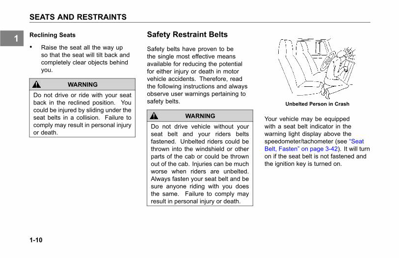
Unbelted Person in Crash
Your vehicle may be equippedwith a seat belt indicator in thewarning light display above thespeedometer/tachometer (see “SeatBelt, Fasten” on page 3-42). It will turnon if the seat belt is not fastened andthe ignition key is turned on.
1-10
1
SEATS AND RESTRAINTS
Lap/Shoulder Belt
The combination lap-shoulder belt isequipped with a locking mechanism.The system adjusts automatically to aperson's size and movements as longas the pull on the belt is slow.
Hard braking or a collision locks thebelt. The belt will also lock whendriving up or down a steep hill or in asharp curve.
To fasten the belt:
1. Grasp the belt tongue.
2. Pull belt in a continuous slowmotion across your chest and lap.
3. Insert belt tongue into buckle oninboard side of seat.
4. Push down until the tongue issecurely locked with an audibleclick. Pull belt to check for properfastening.
° Pull shoulder section to makesure belt fits snugly across thechest.
° The shoulder belt must bepositioned over the shoulder,it must never rest against theneck.
° Belts should fit snugly acrossthe pelvis and chest.Make sure any slack is woundup on the retractor.
To unfasten the belt:
• Push in the release button on thebuckle. The belt will spring out ofthe buckle.
• To release a locked belt, lean backto take the body pressure off ofthe belt.
• To store a lap-shoulder belt, allowthe belt to wind up on the retractorby guiding the belt tongue until thebelt comes to a stop.
Proper Safety Belt Adjustment
Your combination lap-shoulder beltmay need adjustment. Adjust safetybelts properly.
• The lap belt should be worn as lowand tight on the hips as possible.Make sure any slack is taken upby the belt mechanism.
• The shoulder belt should fit snuglyacross your body. It shouldbe positioned midway over theshoulder (that is next to the door);it should never rest against yourneck.
1-11
1
SEATS AND RESTRAINTS
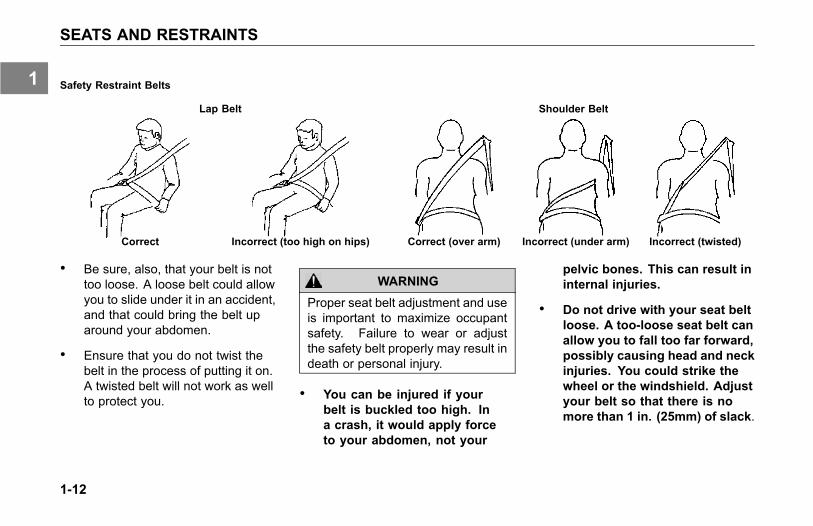
Safety Restraint Belts
Lap Belt Shoulder Belt
Correct Incorrect (too high on hips) Correct (over arm) Incorrect (under arm) Incorrect (twisted)
• Be sure, also, that your belt is nottoo loose. A loose belt could allowyou to slide under it in an accident,and that could bring the belt uparound your abdomen.
• Ensure that you do not twist thebelt in the process of putting it on.A twisted belt will not work as wellto protect you.
WARNING
Proper seat belt adjustment and useis important to maximize occupantsafety. Failure to wear or adjustthe safety belt properly may result indeath or personal injury.
• You can be injured if yourbelt is buckled too high. Ina crash, it would apply forceto your abdomen, not your
pelvic bones. This can result ininternal injuries.
• Do not drive with your seat beltloose. A too-loose seat belt canallow you to fall too far forward,possibly causing head and neckinjuries. You could strike thewheel or the windshield. Adjustyour belt so that there is nomore than 1 in. (25mm) of slack.
1-12
1
SEATS AND RESTRAINTS
WARNING
Do not wear the shoulder part of beltunder your arm or otherwise out ofposition. In a crash your body wouldmove too far forward, increasingthe chance of head and neck injury.Also, the belt would apply too muchforce to the ribs, which are not asstrong as your shoulder bones, andcould cause you to suffer internalinjuries. Wear the shoulder belt overyour shoulder (see Safety RestraintBelts on page 1-12). Failure tocomply may result in personal injuryor death.
WARNING
Do not twist the belt in the processof putting it on. A twisted belt willnot work as well to protect you. In acrash, the full width of the belt wouldnot be protecting you. A twisted beltcould cut into your body and causeinjuries. Straighten the belt beforebuckling it. If you are unable to wearit without twisting it, have your dealeror service person repair it as soonas possible. Failure to comply mayresult in personal injury or death.
Safety Restraint Tips
• Anyone riding in your vehicleshould wear a seat belt. Aresponsible operator sees to itthat everyone in the vehicle ridessafely and that means with a seatbelt.
• Do not strap in more than oneperson with each belt.
• Do not wear a belt over rigid orbreakable objects in or on yourclothing, such as eye glasses,pens, keys, etc., as these maycause injury in an accident.
• Several layers of heavy clothingmay interfere with properpositioning of belts and reducethe overall effectiveness of thesystem.
• Keep belt buckles free of anyobstruction that may preventsecure locking.
• Damaged or worn belts inthe cab/sleeper, subjected toexcessive stretch forces fromcrashes, cuts or tears, or normalwear, must be replaced, they maynot protect you if you have anaccident.
1-13
1

SEATS AND RESTRAINTS
• If belts show damage to any partof assembly, such as webbing,bindings, buckles or retractors,they must be replaced.
• Do not allow safety belts tobecome damaged by gettingcaught in door or seat hardware,or rubbing against sharp objects.
• The belts must be kept clean or theretractors may not work properly.
• Never bleach or dye seat belts:chemicals can weaken them. Do,however, keep them clean byfollowing the care label on thebelts. Let them dry completelybefore allowing them to retract.
• Make sure the belt of theunoccupied passenger seat isfully wound up on its retractor,so that the belt tongue is in itsstowed position. This reduces thepossibility of the tongue becoming
a striking object in case of asudden stop.
• Do not modify or disassemble theseat belts in your vehicle. Theywill not be available to keep youand your passengers safe.
• If any seat belt is not workingproperly, see an authorizedKenworth Dealer for repair orreplacement.
Tether Belts
Tether belts are installed on suspensionseats. They help secure the seat to thefloor to restrain it in case of a suddenstop or an accident.
1-14
1

SEATS AND RESTRAINTS
Fixed Tethers
If your Kenworth has been equippedwith fixed length tethers, no manualadjustment is required. The sameinspection and replacement guidelinesshould be used as stated in SafetyRestraint System - Inspection on page5-55.
WARNING
Do not remove, modify, or replacethe tether belt systemwith a differenttether system. A failed or missingtether belt could allow the seat baseto fully extend in the event of anaccident. Failure to comply mayresult in personal injury or death.
WARNING
Failure to adjust tether belts properlycan cause excessive movementof the seat in an accident. Tetherbelts should be adjusted so thatthey are taut when the seat is in itsmost upward and forward position.Failure to comply may result inpersonal injury or death.
WARNING
Before driving or riding in a vehicle,ensure that there is adequate headclearance at maximum upwardtravel of seat. Shorten the tether beltas necessary to provide adequatehead clearance. Injury or deathmay occur if head clearance is notadequate.
Tether Adjustment
• Make sure that the tether belt isattached to the cab floor and seatframe. It should be routed throughthe buckle on each side.
• Often the attachments are madeusing a split-type hook. Make sureboth halves of the hook are aroundthe anchor bracket.
• To lengthen the tether, turn thebuckle to a right angle to thewebbing. Then pull the buckle.To shorten the tether, pull on thestrap.
1-15
1
SEATS AND RESTRAINTS
Komfort-Lok Feature
Your Kenworth includes a featuredesigned to eliminate cinching andprovide improved safety and comfort.Cinching is the condition where a beltbecomes continually tighter aroundyou during a rough, bouncy ride. Theneed for this feature increases withrough road conditions, particularly overlong distances.
To eliminate cinching, simply activatethe Komfort-Lok feature located on theseat belt webbing at the appropriatetime.
1. Fasten the seat belt accordingto instructions, See Seats AndRestraints on page 1-9.
2. You are now ready to activate theKomfort-Lok. Lean forward to pulla little slack in the belt [maximumof 1 in. (25mm), measured fromthe belt to your chest]. Be sure toallow only a small amount of slack.
See Safety Restraint Belt Warningon page 1-12
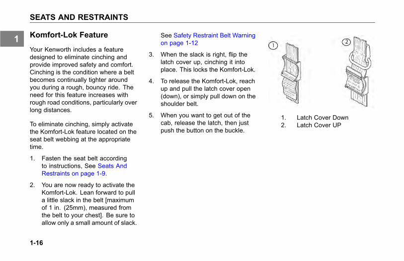
3. When the slack is right, flip thelatch cover up, cinching it intoplace. This locks the Komfort-Lok.
4. To release the Komfort-Lok, reachup and pull the latch cover open(down), or simply pull down on theshoulder belt.
5. When you want to get out of thecab, release the latch, then justpush the button on the buckle.
1. Latch Cover Down2. Latch Cover UP
1-16
1
SEATS AND RESTRAINTS
During Pregnancy
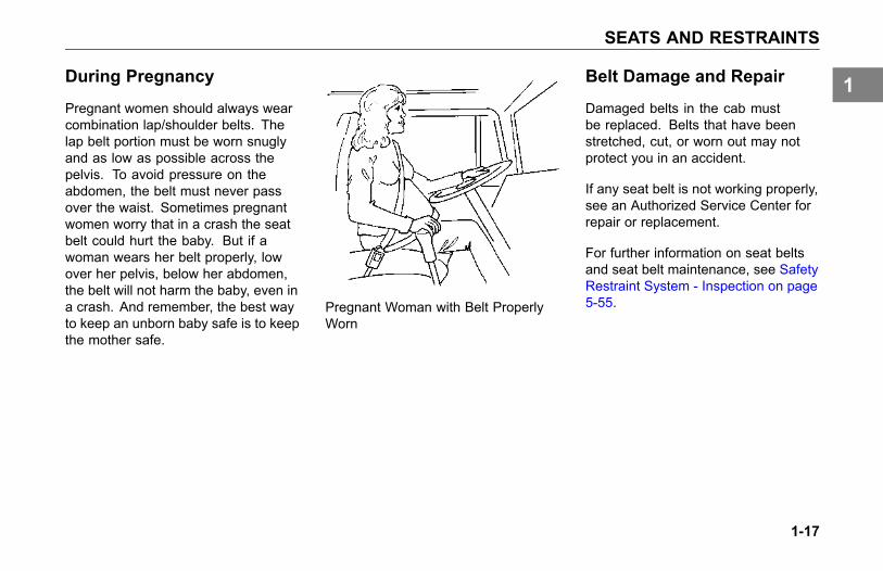
Pregnant women should always wearcombination lap/shoulder belts. Thelap belt portion must be worn snuglyand as low as possible across thepelvis. To avoid pressure on theabdomen, the belt must never passover the waist. Sometimes pregnantwomen worry that in a crash the seatbelt could hurt the baby. But if awoman wears her belt properly, lowover her pelvis, below her abdomen,the belt will not harm the baby, even ina crash. And remember, the best wayto keep an unborn baby safe is to keepthe mother safe.
Pregnant Woman with Belt ProperlyWorn
Belt Damage and Repair
Damaged belts in the cab mustbe replaced. Belts that have beenstretched, cut, or worn out may notprotect you in an accident.
If any seat belt is not working properly,see an Authorized Service Center forrepair or replacement.
For further information on seat beltsand seat belt maintenance, see SafetyRestraint System - Inspection on page5-55.
1-17
1
START-UP
START-UP
Introduction
The following section covers start-upprocedures for getting your Kenworthready for the road.
Door Lock and Keys
Doors can be locked from the inside byusing the lock button. Close the doorthen push the button down to lock.Doors automatically unlock when youopen them from inside, and can belocked from the outside with the keyonly.
As standard equipment, two keys areprovided for the doors and ignition.When necessary, additional locksand keys are provided for storagecompartments.
WARNING
To lessen the chance and/or severityof personal injury in case of anaccident, always lock the doorswhile driving. Along with using thelap/shoulder belts properly, lockingthe doors helps prevent occupantsfrom being thrown from the vehicle.Failure to comply may result inpersonal injury or death.
To lock or unlock the doors fromoutside the cab:
• Insert the key in the door lock.
• Turn the key toward the rear doorframe to lock; forward to unlock.
1-18
1
START-UP
Remote Keyless Entry(Option)
This vehicle may be equipped with aRemote Keyless Entry (RKE) systemthat adds security and convenienceto your Kenworth truck. The systemwill lock or unlock the drivers door andpassengers door with the key fob andalert you with parking lights when theselected doors are locked or unlocked.The system includes two key fobs thatprovide secure rolling code technologythat prevents someone from recordingthe entry signal.
FCC ID: L2C0031T IC: 3432A-0031T
FCC ID: L2C0032R IC: 3432A-0032R
This device complies with Part 15 ofthe FCC Rules and with RSS-210 ofIndustry Canada. Operation is subjectto the following two conditions:
1. This device may not cause harmfulinterference, and
2. This device must accept anyinterference received, includinginterference that may causeundesired operation.
NOTE
Changes or modifications notexpressively approved by the partyresponsible for compliance couldvoid the user's authority to operatethe equipment. The term “IC:”before the radio certification numberonly signifies that Industry Canadatechnical specifications were met.
OperationTo Unlock The Drivers Door
Press the UNLOCK button once. Thedriver's door will unlock and the parkinglights will come on for 40 seconds.
To Unlock The Passengers Door
Press the UNLOCK button once andpress again within 5 seconds. Thepassenger door will unlock.
To Lock Both Doors
Press the LOCK button. The doors willlock and the parking lights will comeon for 2 seconds. If the doors are openthey will not lock.
NOTE
If this system is retrofit on vehiclesbuilt before March 2002, doors maylock when open.
1-19
1
START-UP
The range of the RKE system shouldbe approximately 30 feet. This willbe reduced if it is operated close toother RF sources such as TV/radiotransmitters and cell towers.
Batteries
The key fob uses one CR2032,3V battery. Batteries should lastapproximately three years, dependingon use. Consistently reduced rangeis an indicator that the battery needsreplacement. Batteries are availableat most discount, hardware and drugstores.
To Replace The Battery
1. Remove rear cover from key fob.
2. Remove the battery.
3. Install new battery.
4. Reinstall cover.
5. Synchronize the key fob.
Synchronization
The key fob may need to besynchronized to the vehicle when thebattery is replaced, or when the keyfob has not been used for an extendedperiod time.
1-20
1

START-UP
To Synchronize A Key Fob
1. Hold the key fob near thepassenger door switch module(near the glove box).
2. Press and hold both the Lock andUnlock buttons at the same timefor approximately 7 seconds.
° When the key fob isresynchronized the doorswill lock, then immediatelyunlock.
° If the fob fails to synchronize,it could be programmed to adifferent vehicle or could havefailed.
See Remote Keyless EntryTroubleshooting on page 5-80,for more information.
Cab and Frame Access
The following cab and frame entry/exitprocedure recommendations wereprepared with personal safety foremostin mind.
WARNING
Do not jump out of the cab or get intothe cab without proper caution. Youcould slip or fall, possibly suffering ainjury or death. You could slip andfall if the steps are wet or icy, or ifyou step in fuel, oil, or grease.
To help avoid personal injury due toa slip or fall:
• Always face the vehicle whenaccessing or leaving the cab orframe access area.
• Use three points of contact(two feet one hand or one foottwo hands) to grip the steps or
1-21
1
START-UP
handholds whenever possible andlook where you are going.
• Use even more care when stepsand handholds (or footwear) arewet, coated with ice, snow, mud,oil, fuel, or grease.
WARNING
Do not step on vehicle componentswithout anti-skid surfaces or usecomponents not designed forentry-and-exit use. You could falland injure or kill yourself if you steponto a slippery surface.
• Do not step onto the surface ofa fuel tank. A fuel tank is not astep. The tank surface can getvery slippery, and you might not beable to prevent a fall. Use only thesteps and handholds provided, notchain hooks, quarter fenders, etc.
• Do not climb onto and off the deckplate, use steps and grab handleprovided. If there is no deck plate,or if proper steps and grab handlesare not provided, do not climb ontothe area behind the cab.
• Keep steps clean. Clean any fuel,oil, or grease off the steps beforeentering the cab.
WARNING
Always reinstall the batterycompartment cover (step) beforeentering the cab. Without the batterycover in place, you could slip andfall, resulting in possible injury toyourself.
NOTE
Any alteration (adding bulkheads,headache racks, tool boxes, etc.)behind the cab that affects theutilization of grab handles, deckplates or frame access stepsinstalled by Kenworth must complywith Federal Motor Carrier SafetyRegulation 399.
1-22
1
START-UP
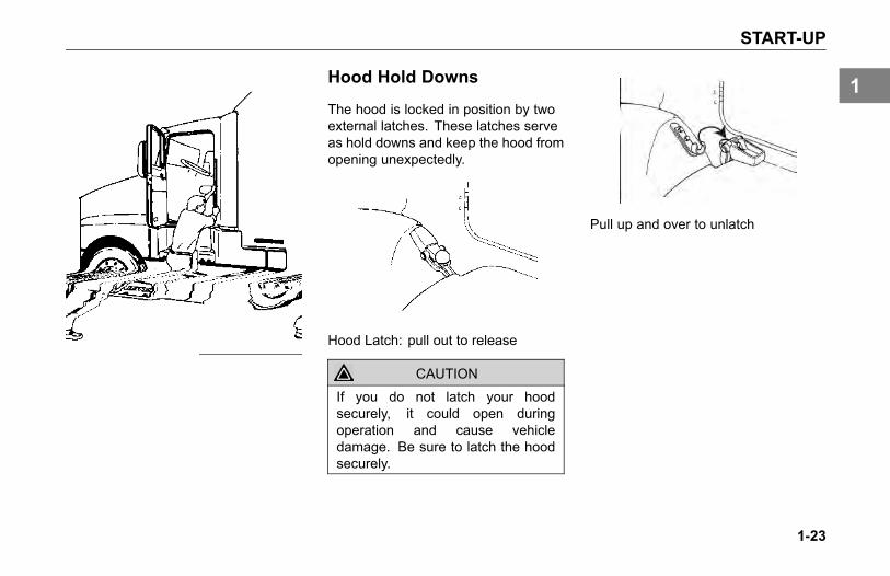
Hood Hold Downs
The hood is locked in position by twoexternal latches. These latches serveas hold downs and keep the hood fromopening unexpectedly.
Hood Latch: pull out to release
CAUTION
If you do not latch your hoodsecurely, it could open duringoperation and cause vehicledamage. Be sure to latch the hoodsecurely.
Pull up and over to unlatch
1-23
1
START-UP
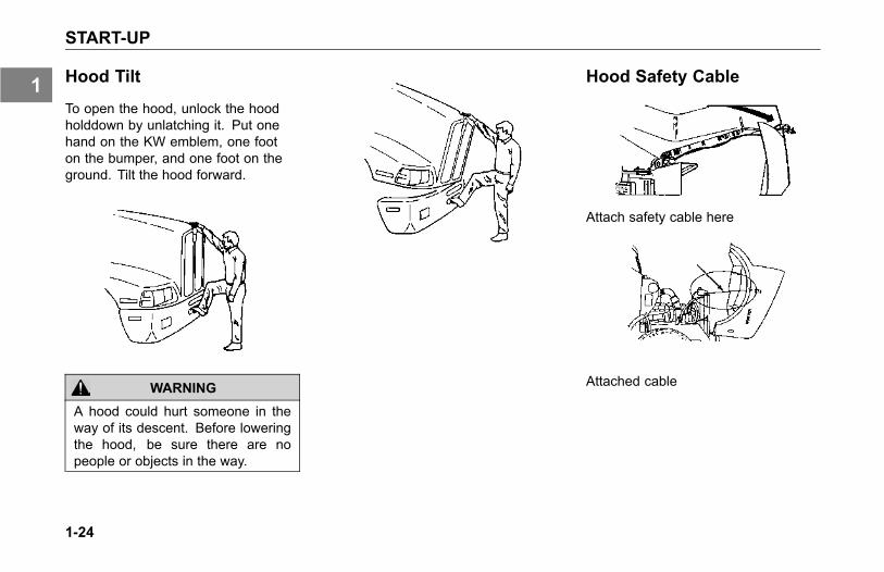
Hood Tilt
To open the hood, unlock the hoodholddown by unlatching it. Put onehand on the KW emblem, one footon the bumper, and one foot on theground. Tilt the hood forward.
WARNING
A hood could hurt someone in theway of its descent. Before loweringthe hood, be sure there are nopeople or objects in the way.
Hood Safety Cable
Attach safety cable here
Attached cable
1-24
1

START-UP
WARNING
If the hood falls, anyone under itcould be injured. Always attach thesafety cable and/or hood stop whenthe hood is in its open position anytime anyone gets under the hood forany reason.
CAUTION
Before lowering the hood, be sureno objects or people are in the way.Look on both sides of the engineand then yell “HOOD DOWN” priorto closing the hood.
WARNING
If the hood is not latched securely,it could open during operation andcause an accident. Be sure the hoodis latched securely before movingthe vehicle.
1-25
1
START-UP
Safe Vehicle Operation
For your safety, as well as thosearound you, be a responsible driver:
• If you drink, do not drive.
• Do not drive if you are tired, ill, orunder emotional stress.
Much has gone into the manufacturingof your Kenworth, including advancedengineering techniques, rigid qualitycontrol, and demanding inspections.These manufacturing processes willbe enhanced by you, the safe driver,who observes the following:
• knows and understands how tooperate the vehicle and all itscontrols
• maintains the vehicle properly
• uses driving skills wisely
For more information, refer toDepartment of TransportationRegulation 392.7, which states thatinterstate commercial motor vehiclesare not to be driven unless the driver issure that certain parts and accessoriesare in working order.
WARNING
Do not drink and drive. Yourreflexes, perceptions, and judgmentcan be affected by even a smallamount of alcohol. You could havea serious or even fatal accident,if you drive after drinking. Pleasedo not drink and drive or ride witha driver who has been drinking.Failure to comply may result indeath, personal injury, equipment orproperty damage.
WARNING
The use of alcohol, drugs, andcertain medications will seriouslyimpair perception, reactions, anddriving ability. These circumstancescan substantially increase the riskof an accident. Failure to complymay result in death, personal injury,equipment or property damage.
WARNING
Do not text and drive. Your reactiontime, perceptions and judgment canbe affected while texting or usingany other form of mobile messagingwhile driving. Failure to complymay result in death, personal injury,equipment or property damage.
1-26
1
START-UP
Vehicle Loading
Compare your vehicle's load capacitywith the total load you are carrying. Ifadjustments need to be made, makethem, do not drive an overloadedvehicle. If you are overloaded or yourload has shifted, your vehicle may beunsafe to drive.
WARNING
Do not exceed the specified loadrating. Overloading can result in lossof vehicle control, either by causingcomponent failures or by affectingvehicle handling. Exceeding loadratings can also shorten the servicelife of the vehicle. Failure to complymay result in personal injury ordeath.
• The components of yourvehicle are designed to providesatisfactory service if thevehicle is not loaded in excessof either the gross vehicle
weight rating (GVWR), or themaximum front and rear grossaxle weight ratings (GAWRs).(Axle weight ratings are listedon the driver's door edge.)
The following are some definitions ofweight you should know:
GVWR: is the Gross Vehicle WeightRating. This is the MAXIMUMWEIGHT your vehicle is allowed tocarry, including the weight of the emptyvehicle, loading platform, occupants,fuel, and any load. Never exceed theGVWR of your vehicle.
GCW: is the actual combined weight,or Gross Combination Weight (GCW),of your vehicle and its load: vehicle,plus trailer(s), plus cargo.
GAWR: is the Gross Axle WeightRating. This is the total weight thatone axle is designed to transmit to the
ground. You will find this number listedon the driver's door edge.
Load Distribution: be sure any loadyou carry is distributed so that no axlehas to support more than its GAWR.
WARNING
An unevenly distributed load or aload too heavy over one axle canaffect the braking and handling ofyour vehicle, which could result inan accident. Even if your load isunder the legal limits, be sure it isdistributed evenly. Failure to complymay result in personal injury, death,equipment or property damage.
1-27
1
START-UP
Emergency Equipment
It is good practice to carry anemergency equipment kit in yourvehicle. One day, if you have aroadside emergency, you will be gladthe following items are with you:
• window scraper
• snow brush
• container or bag of sand or salt
• emergency light
• triangles
• small shovel
• first aid kit
• fire extinguisher
• vehicle recovery hitches (seeVehicle Recovery Guidelines onpage 2-12 for details).
Driver's Check List
To keep your Kenworth in top shapeand maintain a high level of safetyfor you, your passengers, and yourload, make a thorough inspectionevery day before you drive. You willsave maintenance time later, and thesafety checks could help prevent aserious accident. Please remember,too, that Federal Motor Carrier SafetyRegulation 392.7 requires a pre-tripinspection and so do commercialtrucking companies.
You are not expected to become aprofessional mechanic. The purposeof your inspections is to find anythingthat might interfere with the safe andefficient transportation of yourself, anypassengers, and your load. If you dofind something wrong and cannot fix ityourself, have an authorized KenworthDealer or qualified mechanic repairyour vehicle right away.
The following operations are to beperformed by the driver. Performingthese checks and following themaintenance procedures in thismanual will help keep your Kenworthrunning properly.
1-28
1
START-UP
Approaching Your Vehicle
• Check the overall appearance andcondition. Are windows, mirrors,and lights clean and unobstructed?
• Check beneath the vehicle. Arethere signs of fuel, oil, or waterleaks?
• Check for damaged, loose, ormissing parts. Are there partsshowing signs of excessive wearor lack of lubrication? Have aqualified mechanic examine anyquestionable items and repairthem without delay.
• Check your load. Is it securedproperly?
Daily Checks
Engine Compartment Checks - Daily
1. Engine Fluid Levels - add more ifnecessary.
° Engine oil
° Coolant (check while engineis cold)
° Power steering fluid level
2. Engine Belt - check tension andcondition of belts. This is importantto ensure proper air compressorand engine operation.
° Measure the belt tensionat the longest span of thebelt. See Accessory DriveBelts on page 5-91 for furtherinformation on checking belttension.
NOTE
Deflection should be one beltthickness for each foot distancebetween the pulley centers.
° If breaks or tears are found,the belt should be replacedbefore operating the vehicle.
3. Fuel Filter/Water SeparatorDraining - check and drain.Depending on the fuel storagefacility, more frequent drainingmay be required.
4. Windshield washer reservoir fluidlevel - fill if necessary.
5. Battery Cables - check thecondition of the battery andalternator cables for signs ofchafing or rubbing. Make surethat all clamps (straps) holding thecables are present and in goodworking order.
1-29
1
START-UP
6. Hood closed before entering cab.Is it latched properly?
Chassis and Cab Checks - Daily
Before entering the cab and operatingthe vehicle, check the followingequipment for proper maintenance:
1. Lights - do headlights, turn signals,emergency flashers, and exteriorlamps function and are they cleanand adjusted properly?
2. Windows and Mirrors - are theyclean and adjusted properly?
3. Tires and Wheels - are theyinflated properly? Are all wheelcap nuts in place and torquedproperly - tighten if necessary.Check front wheel bearing oillevels. Inspect all tires and wheelsfor damage - correct if found.
4. Suspension - check for loose ormissing fasteners. Check damage
to springs or other suspensionparts.
5. Brake Components - check lines,linkages, chambers, parking andservice brake operation.
6. Air System - are there leaks?
° Air Tanks - drain water fromall air tanks. Make sure thedrain cocks are closed. Thisprocedure is also required forair suspension tanks equippedwith automatic drain valves.
° For further details See Usingthe Brake System on page4-17.
7. Steps and Handholds - checkfor worn surfaces and loose ormissing fasteners.
8. Fluid Tanks - check underneaththe vehicle for signs of fluid leaks.If any are found, correct beforeoperating the vehicle.
9. Fuel Tank Caps - are they secure?
WARNING
Do not remove a fuel tank capnear an open flame. Diesel fuel inthe presence of an ignition source(such as a cigarette) could causean explosion. A mixture of gasolineor alcohol with diesel fuel increasesthis risk of explosion. Use only thefuel and/or additives recommendedfor your engine. Failure to complymay result in personal injury, death,equipment or property damage. SeeRefueling on page 4-74, for moreinformation.
10. Trailer Connections - are theysecure and the lines clear? Ifthey are not being used, are theystored properly?
° Is the trailer spare wheelsecure and inflated?
1-30
1
START-UP
° Is the landing gear up and thehandle secured?
11. Check the fifth wheel. Is thekingpin locked?
° Is the sliding fifth wheellocked?
Cab Interior - Daily
1. Seat - adjust the seat for easyreach of controls.
2. Seat Belts - fasten and adjustsafety restraint belts.
3. Steering Column - adjust for easyreach.
4. Mirrors - check and readjustmirrors if necessary.
5. Lights - turn ignition key to the ONposition and check for warninglights and buzzer. Check operationof turn signals and emergencylights.
6. Instruments - check allinstruments.
7. Windshield - check operation ofwindshield wipers and washers.
8. Horn - check operation of horn.
9. Fuel - check fuel. Is there enoughfuel?
10. Diesel Exhaust Fluid (DEF) -check level. Is there enough fluid?
NOTE
The above items (EngineCompartment, Chassis and Cab,and Prestart Checks) should bechecked daily, as a minimum. Theyare in addition to, not in placeof Federal Motor Carrier SafetyRegulations. These regulationsmay be purchased by writing to:Superintendent of DocumentsU.S. Government Printing OfficeWashington, DC 20402
1-31
1
START-UP
Weekly Operations
1. Battery - check battery andterminals.
2. Wheel Cap Nuts - are they allin place and torqued properly -tighten if necessary. See WheelCap Nut Torque on page 5-127.
3. Other Controls and Wiring - checkfor condition and adjustment
4. Steering Components - checkpitman arm, draglink, and powersteering hoses, etc., for loose,broken, or missing parts.
5. Other Engine CompartmentChecks
• Check condition and fastening ofengine belt, hoses, clamps, andradiator.
• Check the air cleaner, muffler, andexhaust pipes. Are they tight andsecure?
• After Engine Warm-up
° Automatic Transmission- check fluid level in theautomatic transmission oil (ifequipped).
1-32
1
EMERGENCY
WHAT TO DO IF...You Need Roadside Assistance. . . . . . . . . . 2-3Low Air Alarm Turns On . . . . . . . . . . . . . 2-3Stop Engine Lamp Turns On . . . . . . . . . . . 2-4Engine Oil Pressure Lamp Turns On. . . . . . . . 2-4Check Engine Lamp Turns On . . . . . . . . . . 2-5Engine is Overheating . . . . . . . . . . . . . . 2-5Fuse or Relay Blows . . . . . . . . . . . . . . 2-7
JUMP STARTING VEHICLESIntroduction . . . . . . . . . . . . . . . . . . 2-9
VEHICLE RECOVERY AND SPRING BRAKESIntroduction . . . . . . . . . . . . . . . . . 2-12Vehicle Recovery Instructions . . . . . . . . . 2-12Recovery Rigging . . . . . . . . . . . . . . . 2-14Returning Vehicle to Service . . . . . . . . . . 2-15Spring Brakes - Manual Release . . . . . . . . 2-15Freeing the Vehicle from Sand, Mud, Snow and Ice 2-17
2-1
2

WHAT TO DO IF...
WHAT TO DO IF...
You Need RoadsideAssistance
Call toll-FREE 1-800-KW-ASSIST(1-800-592-7747) to talk to someoneat the PACCAR Customer Center.
• Open 24-7-365 days a year
• They can help you get roadsideassistance.
• They have a custom mappingsystem which locates Kenworth &Peterbilt Dealers and IndependentService Providers (ISPs) near youand lists types of services offered,hours of operation and contactinformation.
• They can assist with jump andpull starts, tires, trailers, fines andpermits, chains, towing, hazardousclean-up, out of fuel (roadside),mechanical repairs and preventivemaintenance services.
• They have bilingual agents andaccess to a translation serviceto ensure quality assistancefor customers who speak anylanguage.
• They can’t answer your warrantyquestions but can get you incontact with a Kenworth dealerwho can.
• The PACCAR Customer Centerservice is FREE even if you don’tdrive a Kenworth.
Low Air Alarm Turns On1. Slow down carefully.
2. Move a safe distance off the roadand stop.
3. Place the transmission inneutral (park with automatictransmissions, if equipped) andset the parking brake. (Referto Parking Brake Valve on page3-92 and OPERATING THETRANSMISSION on page 4-64,for transmission shifting andparking brake information.)
4. Turn OFF the engine.
5. Turn ON the emergency flasherand use other warning devices toalert other motorists.
2-3
2

WHAT TO DO IF...
WARNING
If the air pressure falls below 60psi (414 kPa) the spring brakesmay stop the vehicle abruptly, whichcould cause an accident resulting inpersonal injury or death. Observethe red warning lamps on thegauges. If one comes on, do notcontinue to drive the vehicle untilit has been properly repaired orserviced.
If the light and alarm do not turn offat startup, do not try to drive thevehicle until the problem is found andfixed. (Refer to USING THE BRAKESYSTEM on page 4-17, for more brakeinformation.)
Stop Engine Lamp Turns On
WARNING
This should be considered anemergency. You should stop thevehicle as safely as possible andturn OFF the ignition. The vehiclemust be serviced and the problemcorrected before driving again.Failure to do so may cause severeengine or DPF damage, or causean accident which may result inpersonal injury or death
If the Stop Engine warning lampilluminates, it means you have aserious engine system problem.
Engine Oil Pressure LampTurns On
1. Slow down carefully.
2. Move a safe distance off the roadand stop.
3. Place the transmission in parkand set the parking brake. (SeeParking Brake Valve on page3-92 and OPERATING THETRANSMISSION on page 4-64,for transmission shifting andparking brake information.)
4. Turn OFF the engine.
5. Turn ON the emergency flasherand use other warning devices toalert other motorists.
2-4
2
WHAT TO DO IF...
6. Wait a few minutes to allow oil todrain into the engine oil pan, andthen check the oil level. (See OilLevel Check on page 5-87, fordetails on checking oil level.)
7. Add oil if necessary. If the problempersists, contact an authorizedKenworth dealer as soon aspossible.
CAUTION
Continuing to operate your vehiclewith insufficient oil pressure maycause severe engine damage orcause an accident which may resultin equipment or property damage.
It is important to maintain oil pressurewithin acceptable limits. If oil pressuredrops below the minimum psi a RedWarning Lamp on the oil pressuregauge and the Stop Engine Lamp willcome ON.
Check Engine Lamp TurnsOn
Vehicle should be serviced to correctthe problem but the situation shouldnot be considered an emergency. Thevehicle can still be safely driven.
Engine is Overheating1. Reduce engine speed and safely
stop the vehicle. When stopped,place the transmission in Neutraland set the parking brake. (SeeParking Brake Valve on page3-92 and OPERATING THETRANSMISSION on page 4-64,for transmission shifting andparking brake information.) Keepthe engine running.
2. Check to ensure the Oil PressureGauge reads normal. (See EngineOil Pressure Gauge, on page3-57, for further information.)
3. Make sure the engine fan isturning by switching the EngineFan Switch from AUTO to MAN(Manual).
4. Increase the engine speed toabout one-half of full operatingspeed, or 1,100 to 1,200 rpm,maximum.
2-5
2
WHAT TO DO IF...
5. Return the engine speed to normalidle after 2 or 3 minutes.
6. Monitor the engine temperature.After the temperature returns tonormal, allow the engine to idle3 to 5 minutes before shutting itoff. This allows the engine to coolgradually and uniformly.
7. If overheating came fromsevere operating conditions, thetemperature should have cooledby this time. If it has not, stopthe engine and let it cool beforechecking to see if the coolant islow.
° Wait until the coolanttemperature is below 122° F(50° C).
° Protect face, hands, and armsby covering the cap with alarge, thick rag to protectagainst escaping fluid andsteam.
° Carefully and slowly turnthe cap one-quarter of aturn or until it reaches thefirst stop—allowing excesspressure to escape—pushdown and turn for finalremoval.
See Topping Up on page 5-60, forinstructions on checking and filling thecoolant expansion tank.
WARNING
Do not remove the radiator fill capwhile the engine is hot. Scaldingsteam and fluid under pressure mayescape. You could be badly burned.Failure to comply may result inpersonal injury or death.
WARNING
To reduce the chance of death,personal injury, fire and/or vehicledamage from overheated engines,never leave the engine idling withoutan alert driver present. If the engineshould overheat, as indicated bythe engine coolant temperaturelight, immediate action is requiredto correct the condition. Continuedunattended operation of the engine,even for a short time, may resultin serious engine damage or a fire.Failure to comply may result inpersonal injury, death, equipment orproperty damage.
2-6
2
WHAT TO DO IF...
Fuse or Relay Blows
Fuses, circuit breakers, and relaysare located in the Power DistributionBox to the left of the steering columnbehind the clutch pedal. See PowerDistribution Box on page 5-68.
Additional fuses for the alternator,engine electronics and trailer batterycharge circuit may be located in thePower Distribution Center (PDC)inside the battery box and/ or on theengine side of the cab firewall. SeePower Distribution Center (PDC) onpage 5-66.
WARNING
Do not replace a fuse with a fuse of ahigher rating. Doing somay damagethe electrical system and cause afire. Failure to comply may result inpersonal injury, death, equipment orproperty damage.
CAUTION
Before replacing a fuse, turn OFF alllights and accessories and removethe ignition key to avoid damagingthe electrical system.
CAUTION
Never patch fuses with tin foil orwire. This may cause seriousdamage elsewhere in the electricalcircuit, and it may cause a fire.
CAUTION
If a circuit keeps blowing fuses,have the electrical system inspectedfor a short circuit or overload byan authorized Kenworth dealer assoon as possible. Failure to do socould cause serious damage to theelectrical system and/or vehicle.
NOTE
If a fuse of the same rating is notavailable, a fuse of a lower ratingmay be temporarily substituted. Youcan also use a fuse from a circuityou can do temporarily without (forexample an accessory circuit orradio).
All the electrical circuits have fusesto protect them from a short circuit oroverload. If something electrical onyour chassis stops working, the firstthing you should check for is a blownfuse.
1. TurnOFF all lights and accessoriesand remove the ignition key toavoid damaging the electricalsystem.
2. Determine from the chart on thefuse panel which fuse controls thatcomponent.
2-7
2
WHAT TO DO IF...
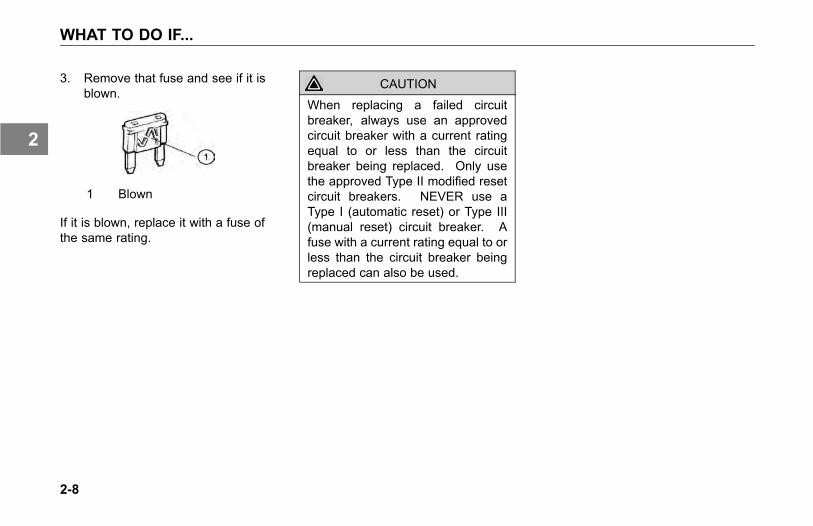
3. Remove that fuse and see if it isblown.
1 Blown
If it is blown, replace it with a fuse ofthe same rating.
CAUTION
When replacing a failed circuitbreaker, always use an approvedcircuit breaker with a current ratingequal to or less than the circuitbreaker being replaced. Only usethe approved Type II modified resetcircuit breakers. NEVER use aType I (automatic reset) or Type III(manual reset) circuit breaker. Afuse with a current rating equal to orless than the circuit breaker beingreplaced can also be used.
2-8
2

JUMP STARTING VEHICLES
JUMP STARTINGVEHICLES
Introduction
Because of the various batteryinstallations and electrical systemoptions, Kenworth does notrecommend that you attempt tojump start your vehicle. If you have abattery problem, it is best to contact aKenworth Dealer or a reputable towingservice.
However, if your battery is discharged(dead), you may be able to start itby using energy from a good batteryin another vehicle. This is termedjump starting. Be sure to follow theprecautions and instructions below.
WARNING
Batteries contain acid that canburn and gasses that can explode.Ignoring safety procedures mayresult in personal injury, death,equipment or property damage.
WARNING
Never jump start a battery nearfire, flames, or electrical sparks.Batteries generate explosive gasesthat could explode. Keep sparks,flame, and lighted cigarettes awayfrom batteries. Failure to complymay result in personal injury, death,equipment or property damage.
WARNING
Never remove or tamper with batterycaps. Ignoring this could allowbattery acid to contact eyes, skin,fabrics, or painted surfaces. Failureto comply may result in personalinjury, death, equipment or propertydamage.
• Be careful that metal tools (orany metal in contact with thepositive terminal) do not contactthe positive battery terminal andany other metal on the vehicleat the same time. Remove metaljewelry and avoid leaning overthe battery.
• If metal jewelry or other metalcomes in contact with electricalcircuits, a short circuit mayoccur causing you to be injured,as well as electrical systemfailure and damage to thevehicle.
2-9
2
JUMP STARTING VEHICLES
To Jump Start Your Vehicle
WARNING
The voltage of the booster batterymust have a 12 volt rating andthe capacity of the booster batteryshould not be lower than that of thedischarged battery. Use of batteriesof different voltage or substantiallydifferent capacity rating may causean explosion. Failure to complymay result in personal injury, death,equipment or property damage.
CAUTIONApplying a higher voltage boosterbattery will cause expensivedamage to sensitive electroniccomponents, such as relays, andthe radio. Failure to comply mayresult in equipment damage.
• Improper hook-up of jumpercables or not following theseprocedures can damage thealternator or cause seriousdamage to both vehicles.
WARNING
To avoid personal injury anddamage to the vehicle, heed allwarnings and instructions of thejumper cable manufacturer.
• The jumper cables must be longenough so that the vehicles donot touch.
Preparing the vehicles:
1. Position the two vehicles together,but do not allow them to touch.
2. Turn OFF all lights, heater, radio,and any other accessory on bothvehicles.
3. Set the parking brakes: pull outthe Yellow button located on thedash.
4. Shift the transmission into parkposition or neutral for manualtransmissions. (See OPERATINGTHE TRANSMISSION on page4-64 and Parking Brake Valve onpage 3-92, for transmission shiftingand parking brake information.)
5. If either vehicle is equipped withbattery disconnects ensure theyare in the "OFF" position prior toconnecting the two vehicles.
2-10
2
JUMP STARTING VEHICLES
Connect the batteries:
1. Attach one end of a jumper cableto the positive (+) terminal of thedischarged (dead) battery. Thiswill have a large red + or P on thebattery case, post, or clamp.
2. Attach the other end of the samecable to the positive (+) terminalof the good (booster) battery.
3. Attach the remaining jumper cableFIRST to the negative (-) terminal(black or N) of the good battery.
4. Attach the other end of thenegative cable to a bare metal partnot bolted to the engine block.IMPORTANT: Always connectpositive (+) to positive (+) andnegative (-) to negative (-).
5. If either vehicle is equipped withbattery disconnects, ensure thatthey are in the"ON" position.
6. Start the engine:
• Start the vehicle that has thegood battery first. Let it run for 5minutes.
• Then start the vehicle that has thedischarged (dead) battery.If the engine fails to start, do notcontinue to crank the starter butcontact the nearest authorizedKenworth Dealer.
Remove jumper cables:
WARNING
When disconnecting jumper cables,make sure they do not get caughtin any moving parts in the enginecompartment. You could be injured.
• Reverse the above procedureexactly when removing the jumpercables. With engine running,disconnect jumper cables fromboth vehicles in the exact reverseorder (Steps 4-1), making sureto first remove the negativecable from the vehicle with thedischarged battery.
2-11
2
VEHICLE RECOVERY AND SPRING BRAKES
VEHICLE RECOVERYAND SPRING BRAKES
Introduction
Your Kenworth may be equipped with aRecovery Device(s) designed for shortdistance recovery purposes only. Useonly the original Kenworth recoverydevice(s) and the instructions below.If your vehicle does not have theproper device contact your authorizedKenworth Dealer.
Vehicle RecoveryInstructions
Refer to the instructions below whentowing your vehicle:
• Use proper towing equipment toprevent damage to the vehicle.
CAUTION
Connect only to the RecoveryDevice(s), as described on thefollowing pages. Do not attachto bumpers or brackets. Useonly equipment designed for thispurpose. Connections to otherstructural parts could damage thevehicle.
CAUTIONRemove the driveline and axleshafts or lift the driving wheelsoff the ground before towing thevehicle. See Driver Controlled MainDifferential Lock on page 4-53. Alllubricating and clutch applicationoil pressure is provided by anengine-driven pump, which will notwork when the engine is stopped.You could seriously damage yourvehicle by towing it with the drivelineconnected and the drive wheels onthe ground.
2-12
2
VEHICLE RECOVERY AND SPRING BRAKES
CAUTIONWhen vehicles are towed, either bywrecker or piggy-back, the lubricantin the top front of the drive axle willdrain to the rear. This will leave thetop components dry. The resultingfriction may seriously damage them.Always remove the main driveshaftand axle shafts before towing yourvehicle.
• See the following references:
° Recovery Rigging on page2-14.
° Driver Controlled MainDifferential Lock on page4-53.
• Use a safety chain system.
• Disconnect driveline.
• Follow state/provincial and locallaws that apply to vehicles in tow.
• Do not tow vehicles at speeds inexcess of 55 mph (90 km/h).
NOTE
For additional informationconcerning heavy duty truckrecovery, see Technology &Maintenance Council (TMC)
• Recommended Practice #602–A— “Front Towing Devices ForTrucks and Tractors.”
• Recommended Practice #602–B— “Recovery Attachment PointsFor Trucks, Tractors, andCombination Vehicles
• Recommended Practice #626— “Heavy Duty Truck TowingProcedures.”
Copies of these can be obtained fromthe following address:
Technology & Maintenance Council950 N. Glebe Road(703) 838-1763Arlington, VA 22203Email: [email protected]://tmc.truckline.com
2-13
2
VEHICLE RECOVERY AND SPRING BRAKES
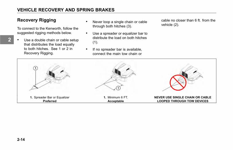
Recovery Rigging
To connect to the Kenworth, follow thesuggested rigging methods below.
• Use a double chain or cable setupthat distributes the load equallyto both hitches. See 1 or 2 inRecovery Rigging.
• Never loop a single chain or cablethrough both hitches (3).
• Use a spreader or equalizer bar todistribute the load on both hitches(1).
• If no spreader bar is available,connect the main tow chain or
cable no closer than 6 ft. from thevehicle (2).
1. Spreader Bar or Equalizer 1. Minimum 6 FT. NEVER USE SINGLE CHAIN OR CABLEPreferred Acceptable LOOPED THROUGH TOW DEVICES
2-14
2

VEHICLE RECOVERY AND SPRING BRAKES
Returning Vehicle to Service
Your vehicle may have lost lubricantwhile being towed. To preventdamage, check the oil level and addoil if necessary.
After adding the specified type andamount of lubricant, drive the vehicle.It should be unloaded. Drive 1 to2 miles (1.5 to 3 km) at a speedlower than 25 mph (40 km/h). Thiswill thoroughly circulate the lubricantthrough the assembly.
Spring Brakes - ManualRelease
In order to tow a vehicle, if there isinsufficient air to release the parkingbrake, the spring brakes can bemanually released.
WARNING
Do not drive vehicle withmalfunctioning brakes. If one ofthe brake circuits should becomeinoperative, braking distances willincrease substantially and handlingcharacteristics while braking will beaffected. You could lose control ofyour vehicle or cause an accident.Have it towed to the nearest dealeror qualified repair facility for repair.Failure to comply may result inpersonal injury, death, equipment orproperty damage.
You may sometimes have to releaseyour vehicle's spring brakes by hand.This could happen if the system air
pressure does not reach operatingpressure because your engine orcompressor is not working properly.You will have to release the springbrakes at the spring brake chambers.
WARNING
Do not disassemble a springbrake chamber. These chamberscontain a powerful spring that iscompressed. Sudden release of thisspring may result in personal injuryor death.
WARNING
Do not operate a vehicle whenthe spring brakes have beenmanually released. Driving avehicle after its spring brakes aremanually released is extremelydangerous. The brakes may notfunction. Failure to comply mayresult in personal injury, death,equipment or property damage.
2-15
2
VEHICLE RECOVERY AND SPRING BRAKES
WARNING
Releasing the spring brakes onan unsecured vehicle could leadto an accident. The vehiclecould roll, which may result inpersonal injury, death, equipmentor property damage. Alwayssecure the vehicle with wheelchocks, chains, or other safemeans to prevent rolling beforemanually releasing the springbrakes.
To move a vehicle immobilized bythe spring brakes due to loss ofair pressure in the brake system,perform the following procedure:
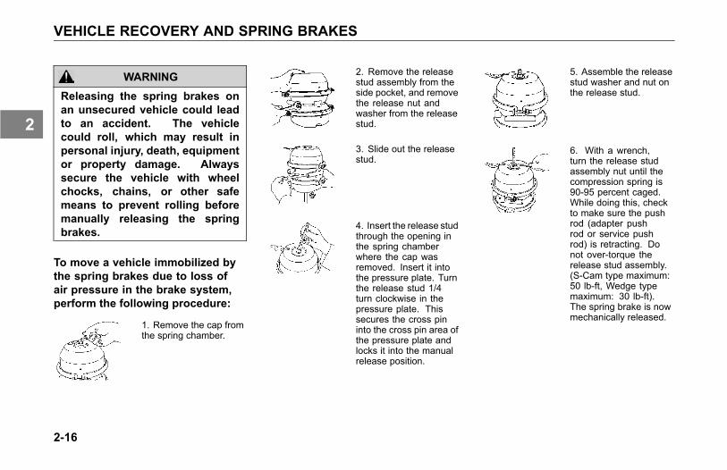
1. Remove the cap fromthe spring chamber.
2. Remove the releasestud assembly from theside pocket, and removethe release nut andwasher from the releasestud.
3. Slide out the releasestud.
4. Insert the release studthrough the opening inthe spring chamberwhere the cap wasremoved. Insert it intothe pressure plate. Turnthe release stud 1/4turn clockwise in thepressure plate. Thissecures the cross pininto the cross pin area ofthe pressure plate andlocks it into the manualrelease position.
5. Assemble the releasestud washer and nut onthe release stud.
6. With a wrench,turn the release studassembly nut until thecompression spring is90-95 percent caged.While doing this, checkto make sure the pushrod (adapter pushrod or service pushrod) is retracting. Donot over-torque therelease stud assembly.(S-Cam type maximum:50 lb-ft, Wedge typemaximum: 30 lb-ft).The spring brake is nowmechanically released.
2-16
2
VEHICLE RECOVERY AND SPRING BRAKES
Freeing the Vehicle fromSand, Mud, Snow and Ice
If the vehicle gets stuck in sand,mud, snow, or ice:
• Move the gearshift lever orselector from First to Reverse.
• Apply light pressure on theaccelerator pedal while thetransmission is in gear.
• Remove your foot from theaccelerator while shifting.
• Do not race the engine.
• For best traction and safety, avoidspinning the wheels.
WARNING
Do not spin the wheels faster than35 mph (55 km/h). Spinning a tire atspeedometer readings faster than35mph (55 km/h) can be dangerous.Tires can explode from spinning toofast. Under some conditions, a tiremay be spinning at a speed twicethat shown on the speedometer.Any resulting tire explosion couldcause injury or death to a bystanderor passenger, as well as extensivevehicle damage: including tire,transmission and/or rear axlemalfunction.
Comply with the followinginstructions to avoid transmissiondamage:
• Always start vehicle in motion withthe shift lever in first gear.
• Be sure that transmission is fullyengaged in gear before releasingthe clutch pedal (manual only).
• Do not shift into reverse while thevehicle is moving.
• Do not permit the vehicle to betowed for long distances withoutremoving the driveshaft.
2-17
2
VEHICLE RECOVERY AND SPRING BRAKES
Tire Chains
If you need tire chains, install them onboth sides of the driving axle.
CAUTION
Chains on the tires of only onetandem axle can damage thedriveline U-joints and the interaxledifferential. Repairs could be costlyand time-consuming. Failure tocomply may result in equipmentdamage.
2-18
2
CONTROLS
ACCESSORIESIntroduction . . . . . . . . . . . . . . . . . . 3-5Radio (Option) . . . . . . . . . . . . . . . . . 3-6Cigarette Lighter and Ashtray (Option) . . . . . . . 3-6Clock . . . . . . . . . . . . . . . . . . . . . 3-7Cab Storage . . . . . . . . . . . . . . . . . . 3-7
HEATING AND AIR CONDITIONINGIntroduction . . . . . . . . . . . . . . . . . . 3-9Precautions . . . . . . . . . . . . . . . . . 3-10Cab Controls . . . . . . . . . . . . . . . . . 3-13
AUDIBLE ALERTSIntroduction . . . . . . . . . . . . . . . . . 3-17
INDICATORSIntroduction . . . . . . . . . . . . . . . . . 3-24
GAUGES AND DISPLAYSIntroduction . . . . . . . . . . . . . . . . . 3-45
3-1
3
CONTROLS
MULTI-FUNCTION DISPLAYIntroduction . . . . . . . . . . . . . . . . . 3-66Alarms, Warning Tones and Visual Indicator Lights 3-66Warning and Information Alert Screens . . . . . 3-67Wingman® ACB Warning Tone / Alert Screens . . 3-71Multi-Function Display . . . . . . . . . . . . . 3-74
SWITCHESIntroduction . . . . . . . . . . . . . . . . . 3-85Dash Switches . . . . . . . . . . . . . . . . 3-86
STEERING COLUMNIntroduction . . . . . . . . . . . . . . . . . 3-100Turn Signal/High Beam Switch . . . . . . . . . 3-100Windshield Wipers/Washer . . . . . . . . . . . 3-102Trailer Brake Hand Valve. . . . . . . . . . . . 3-104Stop/Turn Signal Lamp Operation . . . . . . . . 3-104Adjustable Tilt/Telescoping Column . . . . . . . 3-106Horn . . . . . . . . . . . . . . . . . . . . 3-107
3-2
3

CONTROLS
SmartWheel Multiplex Control System . . . . . . 3-107
MIRRORSIntroduction . . . . . . . . . . . . . . . . . 3-112Power Mirror Switch . . . . . . . . . . . . . . 3-112Mirror Heat Button . . . . . . . . . . . . . . 3-114
3-3
3

ACCESSORIES
ACCESSORIES
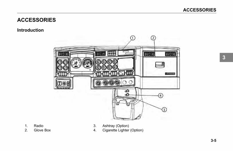
Introduction
1. Radio2. Glove Box
3. Ashtray (Option)4. Cigarette Lighter (Option)
3-5
3
ACCESSORIES
Radio (Option)
As an option, your vehicle has eitheran AM/FM Stereo Receiver or AM/FMStereo with CD.
For instructions on how to operate yourparticular radio, see the manufacturer'sRadio Operating Instructions.
Cigarette Lighter andAshtray (Option)
NOTEThe cigarette lighter will operate withthe ignition key in either the OFF,ACC (accessory), or ON position.
To operate, push in on the knob endof the lighter. After a few moments,the lighter will automatically pop out,glowing hot and ready to use. Afteruse, insert the lighter back into thesocket without pushing all the way in.
The socket of the cigarette lighter maybe used to operate 12 volt, 15 ampereappliances, such as a hand spotlightor small vacuum cleaner.
WARNING
Do not place paper or othercombustible substances in anashtray, it could cause a fire. Keepall burnable materials, besidessmoking materials, out of theashtray. Failure to comply mayresult in personal injury, death,equipment or property damage.
WARNING
Do not exceed thevoltage/amperage capacity of thecigarette lighter. It could result ina fire. Follow all warnings andinstructions in the operator's manualfor the appliance you are using.Failure to comply may result inpersonal injury, death, equipment orproperty damage.
3-6
3
ACCESSORIES
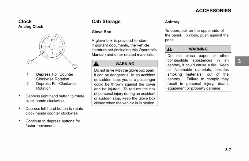
ClockAnalog Clock
1 Depress For CounterClockwise Rotation
2 Depress For ClockwiseRotation
• Depress right hand button to rotateclock hands clockwise.
• Depress left hand button to rotateclock hands counter clockwise.
• Continue to depress buttons forfaster movement.
Cab Storage
Glove Box
A glove box is provided to storeimportant documents, the vehicleliterature set (including this Operator'sManual) and other related materials.
WARNING
Do not drive with the glove box open,it can be dangerous. In an accidentor sudden stop, you or a passengercould be thrown against the coverand be injured. To reduce the riskof personal injury during an accidentor sudden stop, keep the glove boxclosed when the vehicle is in motion.
Ashtray
To open, pull on the upper side ofthe panel. To close, push against thepanel.
WARNING
Do not place paper or othercombustible substances in anashtray, it could cause a fire. Keepall flammable materials, besidessmoking materials, out of theashtray. Failure to comply mayresult in personal injury, death,equipment or property damage.
3-7
3

ACCESSORIES
Interior Compartments
You can choose from a variety ofinterior storage options to store yourpersonal supplies or small tools:
- center console
- map pocket
- overhead storage compartments
- records holder, behind seat
WARNING
Do not carry loose objects in yourcab, it can be dangerous. In asudden stop, or even going overa bump in the road, they could flythrough the air and strike you or apassenger. You could be injuredor even killed. Secure all looseobjects in the cab before moving thevehicle. Carry any heavy objectssuch as luggage in the exteriorstorage compartment and close itsecurely.
Appliances
If your Kenworth is equipped with atelevision, or other appliance, be surethey are compatible with your vehicle'selectrical system. And secure them inthe cab so they cannot come loose ina sudden stop.
WARNING
In a sudden stop or collision a heavyobject in your cab could strike youor anyone with you. You could beinjured or even killed. Secure anyappliance (such as a radio, or TV)you add to your cab.
3-8
3
HEATING AND AIR CONDITIONING
HEATING AND AIRCONDITIONING
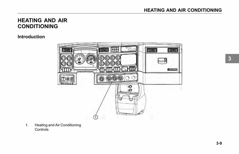
Introduction
1. Heating and Air ConditioningControls
3-9
3

HEATING AND AIR CONDITIONING
The cab heater and A/C controls arelocated together in the center of thedash just to the right of the steeringcolumn.
Precautions
WARNING
Do not drive with visibility reducedby fog, condensation, or froston the windshield. Your viewmay be obscured, which mayresult in personal injury, death,equipment or property damage.For clear visibility and safe drivingit is extremely important foryou to follow the instructionspertaining to the function anduse of the ventilation/heating anddefogging/defrosting system. Ifin doubt, consult your dealer.Maximum heating output and fastdefrosting can be obtained only afterthe engine has reached operatingtemperature.
WARNING
The air conditioning system isunder pressure. If not servicedproperly, it could explode andmay result in personal injury,death or property damage to yourvehicle. Any servicing that requiresdepressurizing and recharging theair conditioning system must beconducted by a qualified technicianwith the right facilities to do the job.
WARNING
Excessive heat may cause thepressurized components of the airconditioning system to explode.Never weld, solder, steam clean, oruse a blow torch near any part ofthe air conditioning system. Failureto comply may result in personalinjury, death, equipment or propertydamage.
3-10
3
HEATING AND AIR CONDITIONING
• If a refrigerant leak develops inthe presence of excessive heator an open flame, hazardousgases may be generated.These gases may causeunconsciousness or death.If you become aware of arefrigerant leak on your vehiclehave your system servicedimmediately and observe thefollowing precautions:
° Stay away from the hotengine until the exhaustmanifold has cooled.
° Do not permit any openflame in the area. Even amatch or a cigarette lightermay generate a hazardousquantity of poisonous gas.
° Do not smoke in the area.Inhaling gaseous refrigerantthrough a cigarette maycause violent illness.
WARNING
Exhaust fumes from the enginecontain carbon monoxide, acolorless and odorless gas. Do notbreathe the engine exhaust gas.A poorly maintained, damaged orcorroded exhaust system can allowcarbon monoxide to enter the cab.Entry of carbon monoxide into thecab is also possible from othervehicles nearby. Failure to properlymaintain your vehicle could causecarbon monoxide to enter the cab,resulting in illness or death.
WARNING
Never idle your vehicle for prolongedperiods of time if you sense thatexhaust fumes are entering the cab.Investigate the cause of the fumesand correct it as soon as possible.If the vehicle must be driven underthese conditions, drive only with thewindows open. Failure to repairthe source of the exhaust fumesmay result in personal injury, death,equipment or property damage.
NOTEKeep the engine exhaust systemand the vehicles cab ventilationsystem properly maintained.
It is recommended that the vehiclesexhaust system and cab/sleeper beinspected:
• By a competent technician every15,000 miles
3-11
3
HEATING AND AIR CONDITIONING
• Whenever a change is noticed inthe sound of the exhaust system
• Whenever the exhaust system,underbody, or cab or sleeper isdamaged
NOTE
To allow for proper operation of thevehicle ventilation system, keepthe inlet grille at the base of thewindshield clear of snow, ice, leavesand other obstructions at all times.
CAUTIONDo not stay in the vehicle with theengine running or idling for morethan 10 minutes with the vehicle'sHeater and A/C ventilation systemin RECIRC or at LOW FAN SPEED.Even with the ventilation system on,running the engine while parked orstopped for prolonged periods oftime is not recommended.
When idling for short periods of time:
• Set the heating or cooling systemto Heat or A/C
• Set the fan to Medium or Highspeed
• Set the controls to FRESH AIR
NOTE
If you are required to idle yourvehicle for long periods of time,install an auxiliary heater orautomatic idle control. Theseauxiliary devices can reduce fuelconsumption and save you money.
NOTE
If you are parked next to idlingvehicles, move your vehicle or donot stay in your vehicle for prolongedperiods of time.
3-12
3
HEATING AND AIR CONDITIONING
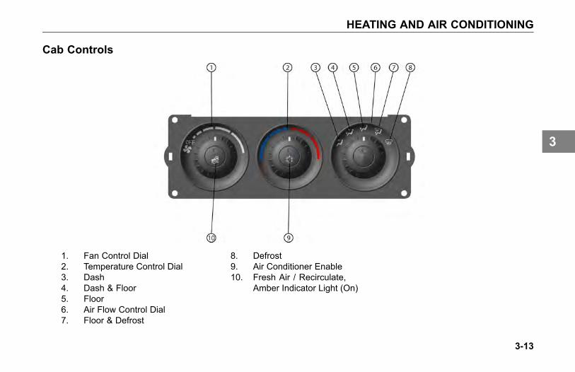
Cab Controls
1. Fan Control Dial2. Temperature Control Dial3. Dash4. Dash & Floor5. Floor6. Air Flow Control Dial7. Floor & Defrost
8. Defrost9. Air Conditioner Enable10. Fresh Air / Recirculate,
Amber Indicator Light (On)
3-13
3
HEATING AND AIR CONDITIONING
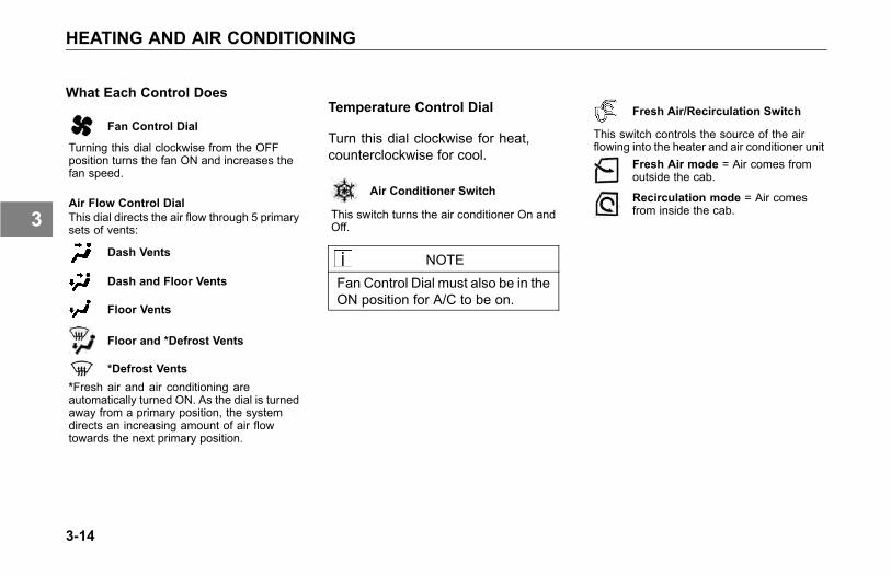
What Each Control Does
Fan Control Dial
Turning this dial clockwise from the OFFposition turns the fan ON and increases thefan speed.
Air Flow Control DialThis dial directs the air flow through 5 primarysets of vents:
Dash Vents
Dash and Floor Vents
Floor Vents
Floor and *Defrost Vents
*Defrost Vents*Fresh air and air conditioning areautomatically turned ON. As the dial is turnedaway from a primary position, the systemdirects an increasing amount of air flowtowards the next primary position.
Temperature Control Dial
Turn this dial clockwise for heat,counterclockwise for cool.
Air Conditioner Switch
This switch turns the air conditioner On andOff.
NOTE
Fan Control Dial must also be in theON position for A/C to be on.
Fresh Air/Recirculation Switch
This switch controls the source of the airflowing into the heater and air conditioner unit
Fresh Air mode = Air comes fromoutside the cab.
Recirculation mode = Air comesfrom inside the cab.
3-14
3

HEATING AND AIR CONDITIONING
How To Use The System
The engine must be running for theheater and air conditioner to generatehot and cold air.
To Cool
There are 2 ways to cool:
a) using cool outside air
b) using air conditioning
a) Outside air is cooler than the inside air:
1.) Push the FreshAir/RecirculationSwitch
to the Fresh Airmode.
2.) Turn ON theFan Control Dial
to the desired fanspeed.
3.) Turn the AirFlow Control Dial to Dash Vents.
b) To cool using air conditioning:
1.) Turn ON theAir ConditioningSwitch.
2.) Push the FreshAir/RecirculateSwitch
to the Fresh Airmode.
3.) Turn ON theFan Control Dial
to the desired fanspeed.
4.) Turn the AirFlow Control Dial to Dash Vents.
5.) Adjust the Temperature Control Dialcounterclockwise until the air temperaturefeels comfortable.
To Heat
1.) Turn ON theFan Control Dial
to the desired fanspeed.
2.) Turn the AirFlow Control Dial to Floor Vents.
3.) Adjust the Temperature Control Dialclockwise until the air temperature feelscomfortable.
To Dehumidify
1.) Push the FreshAir/RecirculateSwitch
to the Fresh Airmode.
2.) Turn ON the Air ConditioningSwitch.
3.) Turn ON theFan Control Dial
to the desired fanspeed.
4.) Adjust the Temperature Control Dial untilthe air temperature feels comfortable.
The air conditioner removes moisturefrom the air while the heater heats theair.
3-15
3
HEATING AND AIR CONDITIONING
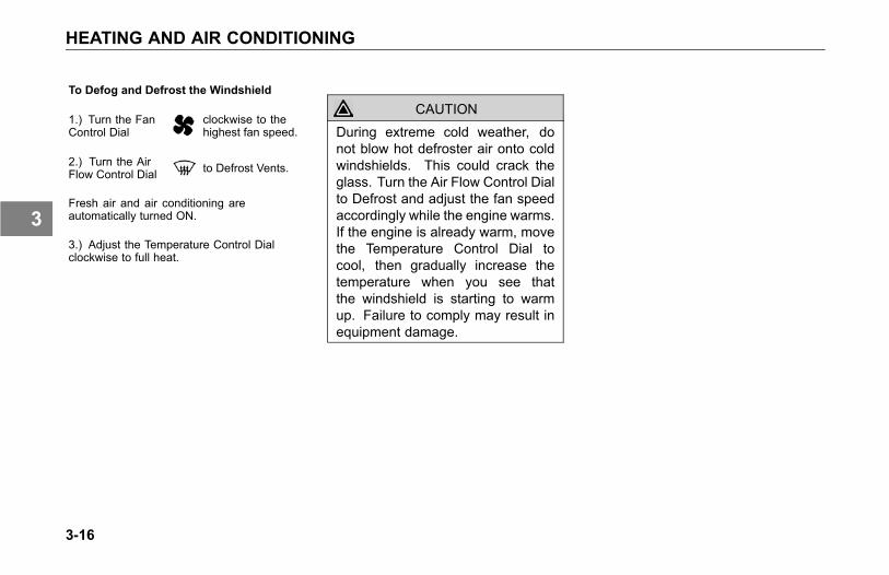
To Defog and Defrost the Windshield
1.) Turn the FanControl Dial
clockwise to thehighest fan speed.
2.) Turn the AirFlow Control Dial to Defrost Vents.
Fresh air and air conditioning areautomatically turned ON.
3.) Adjust the Temperature Control Dialclockwise to full heat.
CAUTIONDuring extreme cold weather, donot blow hot defroster air onto coldwindshields. This could crack theglass. Turn the Air Flow Control Dialto Defrost and adjust the fan speedaccordingly while the engine warms.If the engine is already warm, movethe Temperature Control Dial tocool, then gradually increase thetemperature when you see thatthe windshield is starting to warmup. Failure to comply may result inequipment damage.
3-16
3

AUDIBLE ALERTS
AUDIBLE ALERTS
Introduction
3-17
3
AUDIBLE ALERTS
Your vehicle's dash andinstrumentation uses variousmethods to indicate to you the statusof various systems, or that one ormore of your vehicles systems maybe malfunctioning. The methodto communicate or alert you of aparticular condition is by:
• Audible alarm tone
• Audible warning tone
• Indicator light(s)
In some cases, you may have both analarm or warning tone accompanied byan indicator light(s).
WARNING
Do not ignore any type of toneor lights. These signals tell youthat something is malfunctioning onyour vehicle and provide you anindication of what system is affected.It could be a failure of an importantsystem, such as the brakes, whichcould lead to an accident and mayresult in personal injury, death,equipment or property damage.
Please remember that each Kenworthis custom made. Your instrumentpanel may not look exactly like the onein the illustration.
3-18
3
AUDIBLE ALERTS
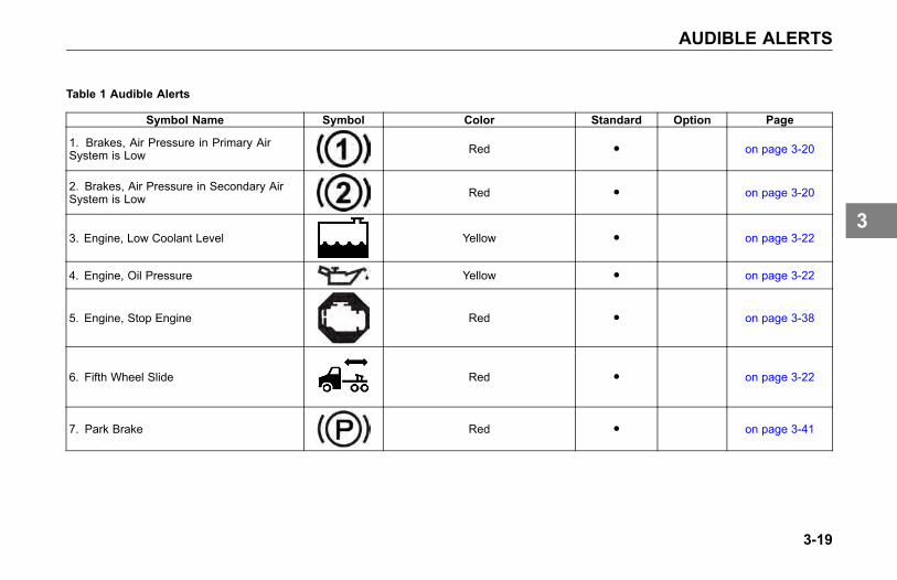
Table 1 Audible Alerts
Symbol Name Symbol Color Standard Option Page
1. Brakes, Air Pressure in Primary AirSystem is Low Red ● on page 3-20
2. Brakes, Air Pressure in Secondary AirSystem is Low Red ● on page 3-20
3. Engine, Low Coolant Level Yellow ● on page 3-22
4. Engine, Oil Pressure Yellow ● on page 3-22
5. Engine, Stop Engine Red ● on page 3-38
6. Fifth Wheel Slide Red ● on page 3-22
7. Park Brake Red ● on page 3-41
3-19
3
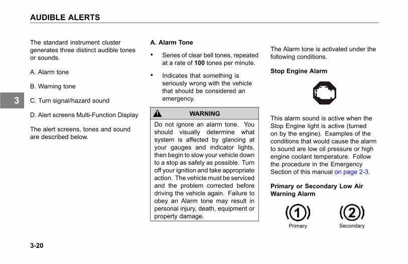
AUDIBLE ALERTS
The standard instrument clustergenerates three distinct audible tonesor sounds.
A. Alarm tone
B. Warning tone
C. Turn signal/hazard sound
D. Alert screens Multi-Function Display
The alert screens, tones and soundare described below.
A. Alarm Tone
• Series of clear bell tones, repeatedat a rate of 100 tones per minute.
• Indicates that something isseriously wrong with the vehiclethat should be considered anemergency.
WARNING
Do not ignore an alarm tone. Youshould visually determine whatsystem is affected by glancing atyour gauges and indicator lights,then begin to slow your vehicle downto a stop as safely as possible. Turnoff your ignition and take appropriateaction. The vehiclemust be servicedand the problem corrected beforedriving the vehicle again. Failure toobey an Alarm tone may result inpersonal injury, death, equipment orproperty damage.
The Alarm tone is activated under thefollowing conditions.
Stop Engine Alarm
This alarm sound is active when theStop Engine light is active (turnedon by the engine). Examples of theconditions that would cause the alarmto sound are low oil pressure or highengine coolant temperature. Followthe procedure in the EmergencySection of this manual on page 2-3.
Primary or Secondary Low AirWarning Alarm
Primary Secondary
3-20
3
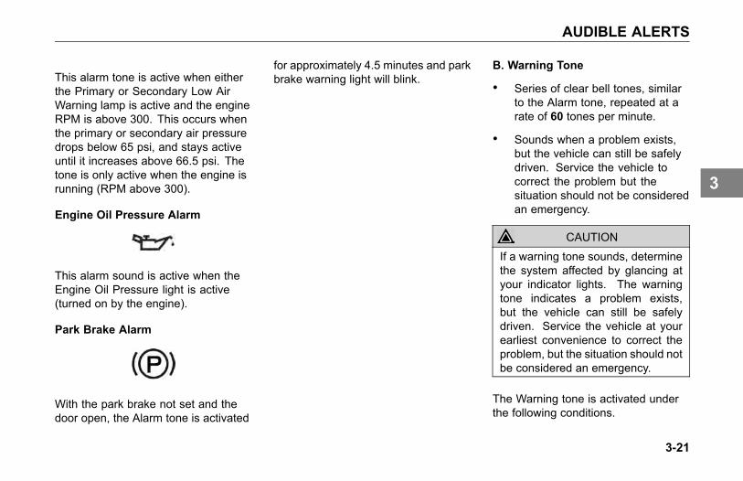
AUDIBLE ALERTS
This alarm tone is active when eitherthe Primary or Secondary Low AirWarning lamp is active and the engineRPM is above 300. This occurs whenthe primary or secondary air pressuredrops below 65 psi, and stays activeuntil it increases above 66.5 psi. Thetone is only active when the engine isrunning (RPM above 300).
Engine Oil Pressure Alarm
This alarm sound is active when theEngine Oil Pressure light is active(turned on by the engine).
Park Brake Alarm
With the park brake not set and thedoor open, the Alarm tone is activated
for approximately 4.5 minutes and parkbrake warning light will blink.
B. Warning Tone
• Series of clear bell tones, similarto the Alarm tone, repeated at arate of 60 tones per minute.
• Sounds when a problem exists,but the vehicle can still be safelydriven. Service the vehicle tocorrect the problem but thesituation should not be consideredan emergency.
CAUTION
If a warning tone sounds, determinethe system affected by glancing atyour indicator lights. The warningtone indicates a problem exists,but the vehicle can still be safelydriven. Service the vehicle at yourearliest convenience to correct theproblem, but the situation should notbe considered an emergency.
The Warning tone is activated underthe following conditions.
3-21
3
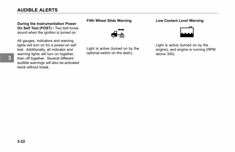
AUDIBLE ALERTS
During the Instrumentation PowerOn Self Test (POST) - Two bell tonessound when the ignition is turned on.
All gauges, indicators and warninglights will turn on for a power-on selftest. Additionally, all indicator andwarning lights will turn on together,then off together. Several differentaudible warnings will also be activatedtwice without break.
Fifth Wheel Slide Warning
Light is active (turned on by theoptional switch on the dash).
Low Coolant Level Warning
Light is active (turned on by theengine), and engine is running (RPMabove 300).
3-22
3
AUDIBLE ALERTS
C. Turn Signal/Hazard Sound
• Generates a tic-toc sound, similarto a sound and function of amechanical flasher.
• Sounds anytime the turn signal orhazard switch is turned On.
NOTE
If the vehicle turn signals and turnsignal indicators in the dash gaugecluster ever begin flashing at anaccelerated rate (115 cycles perminute) when the turn signal lever isin the OFF (center) position, or whena Right/Left turn has been selected,the problem may be related to afailed turn signal switch or turn signalmodule. In either case, the problemis not a failed bulb. Contact yournearest authorized Kenworth Dealerto have the problem corrected assoon as possible.
3-23
3
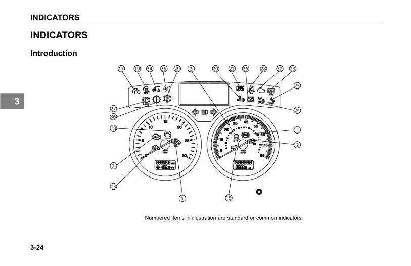
INDICATORS
INDICATORS
Introduction
Numbered items in illustration are standard or common indicators.
3-24
3
INDICATORS
Your vehicle's dash andinstrumentation uses variousmethods to indicate to you the statusof various systems, or that one ormore of your vehicles systems maybe malfunctioning. The methodto communicate or alert you of aparticular condition is by:
• Audible alarm tone
• Audible warning tone
• Indicator light(s)
In some cases, you may have both analarm or warning tone accompanied byan indicator light(s).
WARNING
Do not ignore any type of toneor lights. These signals tell youthat something is malfunctioning onyour vehicle and provide you anindication of what system is affected.It could be a failure of an importantsystem, such as the brakes, whichcould lead to an accident and mayresult in personal injury, death,equipment or property damage.
Please remember that each Kenworthis custom made. Your instrumentpanel may not look exactly like the onein the illustration.
3-25
3
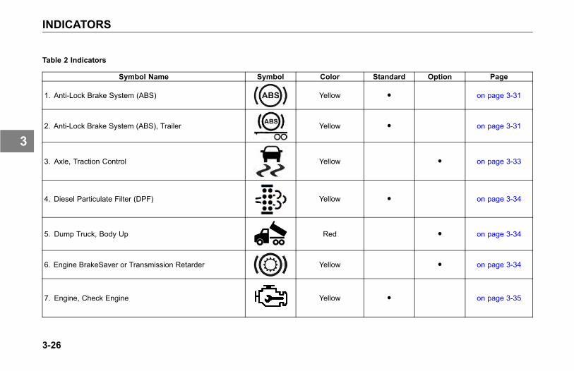
INDICATORS
Table 2 Indicators
Symbol Name Symbol Color Standard Option Page
1. Anti-Lock Brake System (ABS) Yellow ● on page 3-31
2. Anti-Lock Brake System (ABS), Trailer Yellow ● on page 3-31
3. Axle, Traction Control Yellow ● on page 3-33
4. Diesel Particulate Filter (DPF) Yellow ● on page 3-34
5. Dump Truck, Body Up Red ● on page 3-34
6. Engine BrakeSaver or Transmission Retarder Yellow ● on page 3-34
7. Engine, Check Engine Yellow ● on page 3-35
3-26
3
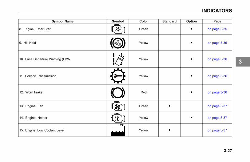
INDICATORS
Symbol Name Symbol Color Standard Option Page
8. Engine, Ether Start Green ● on page 3-35
9. Hill Hold Yellow ● on page 3-35
10. Lane Departure Warning (LDW) Yellow ● on page 3-36
11. Service Transmission Yellow ● on page 3-36
12. Worn brake Red ● on page 3-36
13. Engine, Fan Green ● on page 3-37
14. Engine, Heater Yellow ● on page 3-37
15. Engine, Low Coolant Level Yellow ● on page 3-37
3-27
3
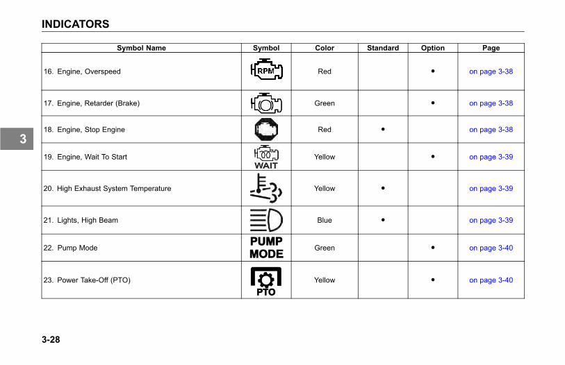
INDICATORS
Symbol Name Symbol Color Standard Option Page
16. Engine, Overspeed Red ● on page 3-38
17. Engine, Retarder (Brake) Green ● on page 3-38
18. Engine, Stop Engine Red ● on page 3-38
19. Engine, Wait To Start Yellow ● on page 3-39
20. High Exhaust System Temperature Yellow ● on page 3-39
21. Lights, High Beam Blue ● on page 3-39
22. Pump Mode Green ● on page 3-40
23. Power Take-Off (PTO) Yellow ● on page 3-40
3-28
3
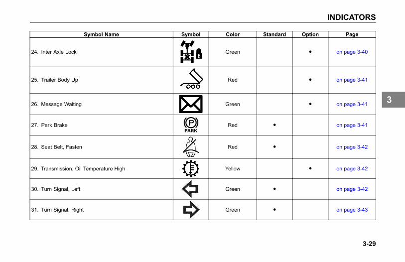
INDICATORS
Symbol Name Symbol Color Standard Option Page
24. Inter Axle Lock Green ● on page 3-40
25. Trailer Body Up Red ● on page 3-41
26. Message Waiting Green ● on page 3-41
27. Park Brake Red ● on page 3-41
28. Seat Belt, Fasten Red ● on page 3-42
29. Transmission, Oil Temperature High Yellow ● on page 3-42
30. Turn Signal, Left Green ● on page 3-42
31. Turn Signal, Right Green ● on page 3-43
3-29
3
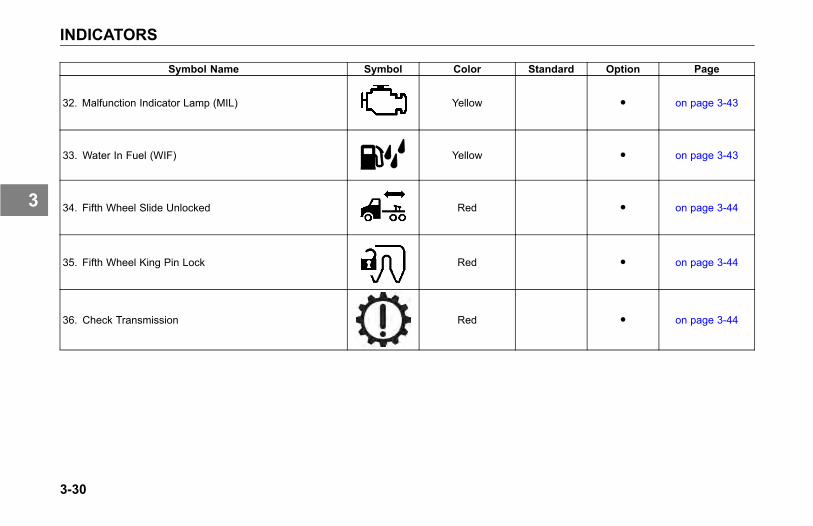
INDICATORS
Symbol Name Symbol Color Standard Option Page
32. Malfunction Indicator Lamp (MIL) Yellow ● on page 3-43
33. Water In Fuel (WIF) Yellow ● on page 3-43
34. Fifth Wheel Slide Unlocked Red ● on page 3-44
35. Fifth Wheel King Pin Lock Red ● on page 3-44
36. Check Transmission Red ● on page 3-44
3-30
3
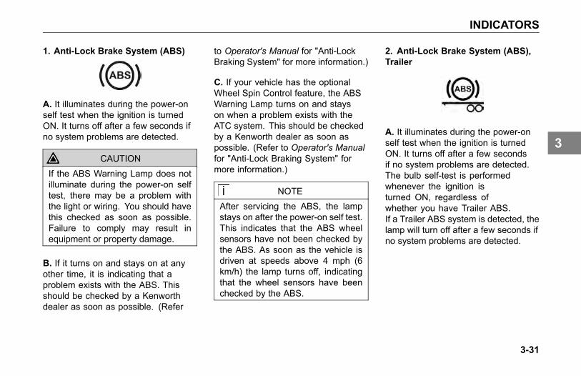
INDICATORS
1. Anti-Lock Brake System (ABS)
A. It illuminates during the power-onself test when the ignition is turnedON. It turns off after a few seconds ifno system problems are detected.
CAUTION
If the ABS Warning Lamp does notilluminate during the power-on selftest, there may be a problem withthe light or wiring. You should havethis checked as soon as possible.Failure to comply may result inequipment or property damage.
B. If it turns on and stays on at anyother time, it is indicating that aproblem exists with the ABS. Thisshould be checked by a Kenworthdealer as soon as possible. (Refer
to Operator's Manual for "Anti-LockBraking System" for more information.)
C. If your vehicle has the optionalWheel Spin Control feature, the ABSWarning Lamp turns on and stayson when a problem exists with theATC system. This should be checkedby a Kenworth dealer as soon aspossible. (Refer to Operator's Manualfor "Anti-Lock Braking System" formore information.)
NOTE
After servicing the ABS, the lampstays on after the power-on self test.This indicates that the ABS wheelsensors have not been checked bythe ABS. As soon as the vehicle isdriven at speeds above 4 mph (6km/h) the lamp turns off, indicatingthat the wheel sensors have beenchecked by the ABS.
2. Anti-Lock Brake System (ABS),Trailer
A. It illuminates during the power-onself test when the ignition is turnedON. It turns off after a few secondsif no system problems are detected.The bulb self-test is performedwhenever the ignition isturned ON, regardless ofwhether you have Trailer ABS.If a Trailer ABS system is detected, thelamp will turn off after a few seconds ifno system problems are detected.
3-31
3
INDICATORS
CAUTION
If the Trailer ABS Warning Lampdoes not turn on during the power-onself test, there may be a problemwith the light or wiring. You shouldhave this checked as soon aspossible.
B. If it turns on at any other time,it is indicating that a problem existswith the Power Line Communication(PLC) trailer ABS. This should bechecked by a Kenworth dealer as soonas possible. (Refer to "Trailer ABS"in the Operator's Manual for moreinformation.)
C. If your tractor and trailer havethe "Special Trailer ABS (WithoutPLC) Option", (Refer to "SpecialTrailer ABS (Without PLC) Option"in the Operator's Manual for moreinformation.) this lamp will turn onwhen the trailer ABS has a systemproblem. This should be checked by a
Kenworth dealer as soon as possible.Power on self test for trailer ABS iscontrolled by the cluster and occursunder all conditions.
CAUTION
If the Trailer ABS Warning Lampdoes not turn on during the power-onself test there may be a problem withthe light or wiring. You should havethis checked as soon as possible.
NOTE
Tractors/Trucks and trailers builtafter 3/1/01 must be able to turnon an In-Cab Trailer ABS WarningLamp (per U.S. FMVSS121). Theindustry chose PLC as the standardmethod to turn it on. (Refer to"Trailer ABS" in the Operator'sManual for more information.)
NOTE
The Trailer ABS Warning Lampwill not turn on when connected totrailers with ABS (but without PLC)powered through the primary 7-waytrailer light line. Use the lamp on thedrivers side of the trailer to identifytrailer ABS problems.
NOTEFor doubles or triples, the lamp doesnot distinguish between trailers. AnABS problem in any of the trailerswill activate the Trailer ABSWarningLamp.
3-32
3
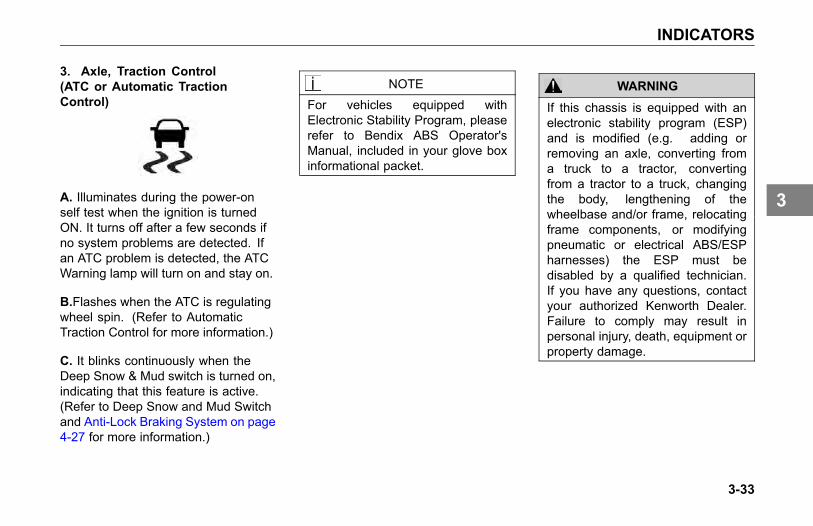
INDICATORS
3. Axle, Traction Control(ATC or Automatic TractionControl)
A. Illuminates during the power-onself test when the ignition is turnedON. It turns off after a few seconds ifno system problems are detected. Ifan ATC problem is detected, the ATCWarning lamp will turn on and stay on.
B.Flashes when the ATC is regulatingwheel spin. (Refer to AutomaticTraction Control for more information.)
C. It blinks continuously when theDeep Snow & Mud switch is turned on,indicating that this feature is active.(Refer to Deep Snow and Mud Switchand Anti-Lock Braking System on page4-27 for more information.)
NOTEFor vehicles equipped withElectronic Stability Program, pleaserefer to Bendix ABS Operator'sManual, included in your glove boxinformational packet.
WARNING
If this chassis is equipped with anelectronic stability program (ESP)and is modified (e.g. adding orremoving an axle, converting froma truck to a tractor, convertingfrom a tractor to a truck, changingthe body, lengthening of thewheelbase and/or frame, relocatingframe components, or modifyingpneumatic or electrical ABS/ESPharnesses) the ESP must bedisabled by a qualified technician.If you have any questions, contactyour authorized Kenworth Dealer.Failure to comply may result inpersonal injury, death, equipment orproperty damage.
3-33
3
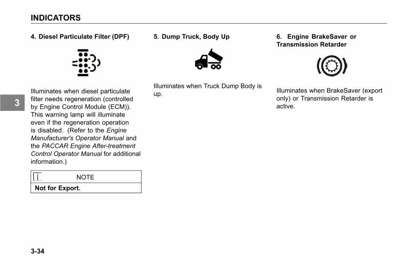
INDICATORS
4. Diesel Particulate Filter (DPF)
Illuminates when diesel particulatefilter needs regeneration (controlledby Engine Control Module (ECM)).This warning lamp will illuminateeven if the regeneration operationis disabled. (Refer to the EngineManufacturer's Operator Manual andthe PACCAR Engine After-treatmentControl Operator Manual for additionalinformation.)
NOTE
Not for Export.
5. Dump Truck, Body Up
Illuminates when Truck Dump Body isup.
6. Engine BrakeSaver orTransmission Retarder
Illuminates when BrakeSaver (exportonly) or Transmission Retarder isactive.
3-34
3
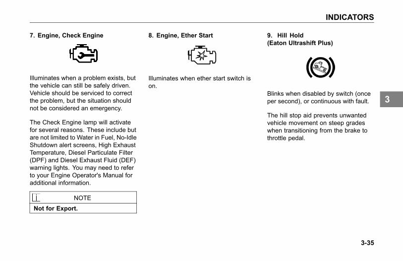
INDICATORS
7. Engine, Check Engine
Illuminates when a problem exists, butthe vehicle can still be safely driven.Vehicle should be serviced to correctthe problem, but the situation shouldnot be considered an emergency.
The Check Engine lamp will activatefor several reasons. These include butare not limited to Water in Fuel, No-IdleShutdown alert screens, High ExhaustTemperature, Diesel Particulate Filter(DPF) and Diesel Exhaust Fluid (DEF)warning lights. You may need to referto your Engine Operator's Manual foradditional information.
NOTE
Not for Export.
8. Engine, Ether Start
Illuminates when ether start switch ison.
9. Hill Hold(Eaton Ultrashift Plus)
Blinks when disabled by switch (onceper second), or continuous with fault.
The hill stop aid prevents unwantedvehicle movement on steep gradeswhen transitioning from the brake tothrottle pedal.
3-35
3

INDICATORS
10. Lane Departure Warning (LDW)
Illuminates when optional LDW systemis not able to track the vehicle'sposition within the lane.
NOTEFor vehicles equipped with LaneDeparture Warning, please refer toLane Departure Warning Driver'sGuide for additional information.
11. Service Transmission
Illuminates when Allison 1000/2000transmission requires service.
12. Worn Brake
Illuminates when brake pads onoptional Brake Warning Systemrequire replacement.
3-36
3
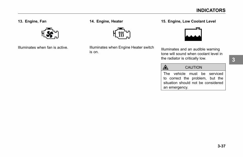
INDICATORS
13. Engine, Fan
Illuminates when fan is active.
14. Engine, Heater
Illuminates when Engine Heater switchis on.
15. Engine, Low Coolant Level
Illuminates and an audible warningtone will sound when coolant level inthe radiator is critically low.
CAUTIONThe vehicle must be servicedto correct the problem, but thesituation should not be consideredan emergency.
3-37
3
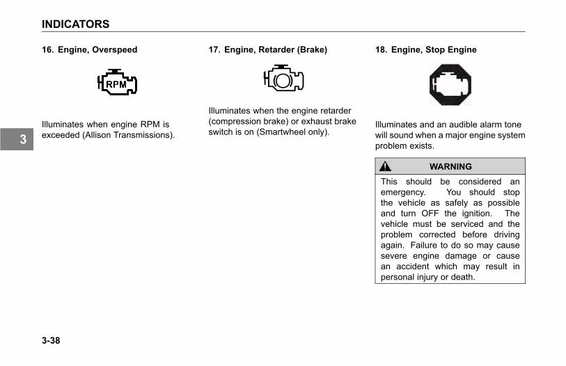
INDICATORS
16. Engine, Overspeed
Illuminates when engine RPM isexceeded (Allison Transmissions).
17. Engine, Retarder (Brake)
Illuminates when the engine retarder(compression brake) or exhaust brakeswitch is on (Smartwheel only).
18. Engine, Stop Engine
Illuminates and an audible alarm tonewill sound when a major engine systemproblem exists.
WARNING
This should be considered anemergency. You should stopthe vehicle as safely as possibleand turn OFF the ignition. Thevehicle must be serviced and theproblem corrected before drivingagain. Failure to do so may causesevere engine damage or causean accident which may result inpersonal injury or death.
3-38
3
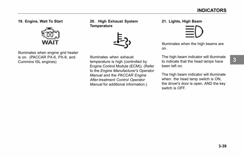
INDICATORS
19. Engine, Wait To Start
Illuminates when engine grid heateris on. (PACCAR PX-6, PX-8, andCummins ISL engines)
20. High Exhaust SystemTemperature
Illuminates when exhausttemperature is high (controlled byEngine Control Module (ECM)). (Referto the Engine Manufacturer's OperatorManual and the PACCAR EngineAfter-treatment Control OperatorManual for additional information.)
21. Lights, High Beam
Illuminates when the high beams areon.
The high beam indicator will illuminateto indicate that the head lamps havebeen left on.
The high beam indicator will illuminatewhen: the head lamp switch is ON,the driver's door is open, AND the keyswitch is OFF.
3-39
3
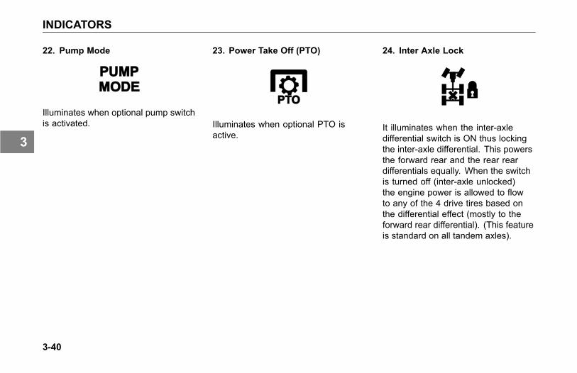
INDICATORS
22. Pump Mode
Illuminates when optional pump switchis activated.
23. Power Take Off (PTO)
Illuminates when optional PTO isactive.
24. Inter Axle Lock
It illuminates when the inter-axledifferential switch is ON thus lockingthe inter-axle differential. This powersthe forward rear and the rear reardifferentials equally. When the switchis turned off (inter-axle unlocked)the engine power is allowed to flowto any of the 4 drive tires based onthe differential effect (mostly to theforward rear differential). (This featureis standard on all tandem axles).
3-40
3
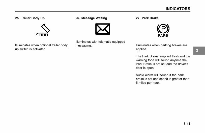
INDICATORS
25. Trailer Body Up
Illuminates when optional trailer bodyup switch is activated.
26. Message Waiting
Illuminates with telematic equippedmessaging.
27. Park Brake
Illuminates when parking brakes areapplied.
The Park Brake lamp will flash and thewarning tone will sound anytime thePark Brake is not set and the driver'sdoor is open.
Audio alarm will sound if the parkbrake is set and speed is greater than5 miles per hour.
3-41
3
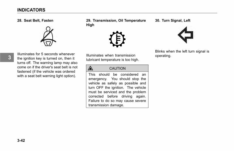
INDICATORS
28. Seat Belt, Fasten
Illuminates for 5 seconds wheneverthe ignition key is turned on, then itturns off. The warning lamp may alsocome on if the driver's seat belt is notfastened (if the vehicle was orderedwith a seat belt warning light option).
29. Transmission, Oil TemperatureHigh
Illuminates when transmissionlubricant temperature is too high.
CAUTIONThis should be considered anemergency. You should stop thevehicle as safely as possible andturn OFF the ignition. The vehiclemust be serviced and the problemcorrected before driving again.Failure to do so may cause severetransmission damage.
30. Turn Signal, Left
Blinks when the left turn signal isoperating.
3-42
3
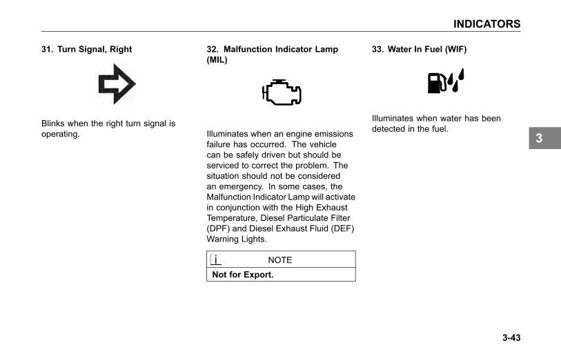
INDICATORS
31. Turn Signal, Right
Blinks when the right turn signal isoperating.
32. Malfunction Indicator Lamp(MIL)
Illuminates when an engine emissionsfailure has occurred. The vehiclecan be safely driven but should beserviced to correct the problem. Thesituation should not be consideredan emergency. In some cases, theMalfunction Indicator Lamp will activatein conjunction with the High ExhaustTemperature, Diesel Particulate Filter(DPF) and Diesel Exhaust Fluid (DEF)Warning Lights.
NOTE
Not for Export.
33. Water In Fuel (WIF)
Illuminates when water has beendetected in the fuel.
3-43
3
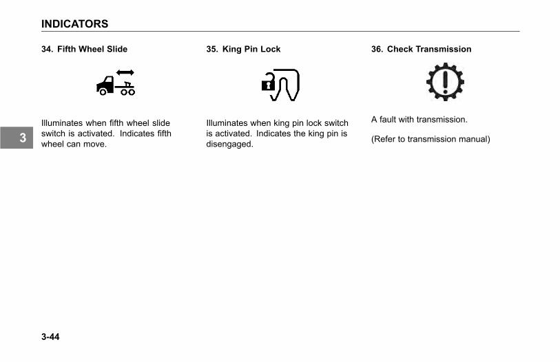
INDICATORS
34. Fifth Wheel Slide
Illuminates when fifth wheel slideswitch is activated. Indicates fifthwheel can move.
35. King Pin Lock
Illuminates when king pin lock switchis activated. Indicates the king pin isdisengaged.
36. Check Transmission
A fault with transmission.
(Refer to transmission manual)
3-44
3
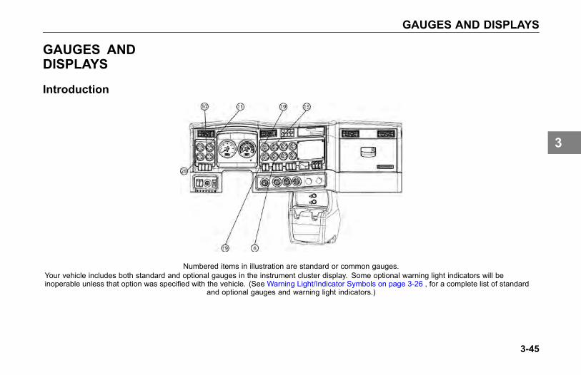
GAUGES AND DISPLAYS
GAUGES ANDDISPLAYS
Introduction
Numbered items in illustration are standard or common gauges.Your vehicle includes both standard and optional gauges in the instrument cluster display. Some optional warning light indicators will beinoperable unless that option was specified with the vehicle. (See Warning Light/Indicator Symbols on page 3-26 , for a complete list of standard
and optional gauges and warning light indicators.)
3-45
3
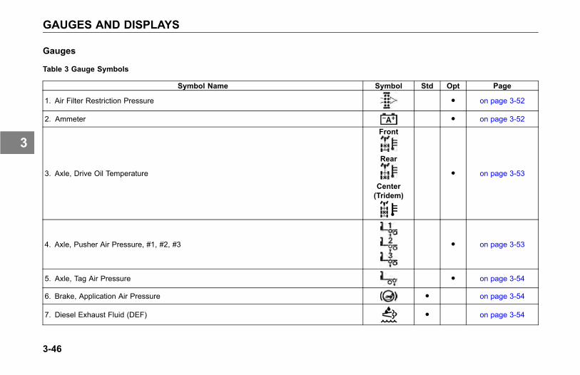
GAUGES AND DISPLAYS
Gauges
Table 3 Gauge Symbols
Symbol Name Symbol Std Opt Page
1. Air Filter Restriction Pressure ● on page 3-52
2. Ammeter ● on page 3-52
3. Axle, Drive Oil Temperature
Front
Rear
Center(Tridem)
● on page 3-53
4. Axle, Pusher Air Pressure, #1, #2, #3 ● on page 3-53
5. Axle, Tag Air Pressure ● on page 3-54
6. Brake, Application Air Pressure ● on page 3-54
7. Diesel Exhaust Fluid (DEF) ● on page 3-54
3-46
3
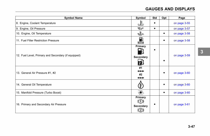
GAUGES AND DISPLAYS
Symbol Name Symbol Std Opt Page
8. Engine, Coolant Temperature ● on page 3-55
9. Engine, Oil Pressure ● on page 3-57
10. Engine, Oil Temperature ● on page 3-58
11. Fuel Filter Restriction Pressure ● on page 3-58
Primary●
12. Fuel Level, Primary and Secondary (if equipped) Secondary●
on page 3-59
13. General Air Pressure #1, #2
#1
#2● on page 3-60
14. General Oil Temperature ● on page 3-60
15. Manifold Pressure (Turbo Boost) ● on page 3-60
16. Primary and Secondary Air Pressure
Primary
Secondary● on page 3-61
3-47
3
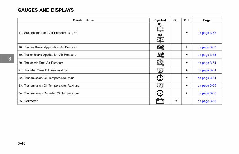
GAUGES AND DISPLAYS
Symbol Name Symbol Std Opt Page
17. Suspension Load Air Pressure, #1, #2
#1
#2● on page 3-62
18. Tractor Brake Application Air Pressure ● on page 3-63
19. Trailer Brake Application Air Pressure ● on page 3-63
20. Trailer Air Tank Air Pressure ● on page 3-64
21. Transfer Case Oil Temperature ● on page 3-64
22. Transmission Oil Temperature, Main ● on page 3-64
23. Transmission Oil Temperature, Auxiliary ● on page 3-65
24. Transmission Retarder Oil Temperature ● on page 3-65
25. Voltmeter ● on page 3-65
3-48
3
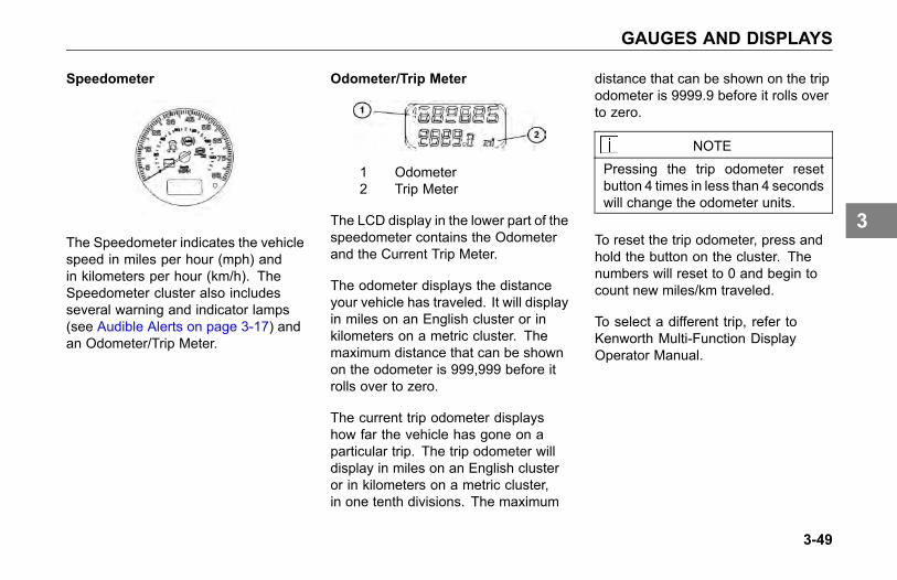
GAUGES AND DISPLAYS
Speedometer
The Speedometer indicates the vehiclespeed in miles per hour (mph) andin kilometers per hour (km/h). TheSpeedometer cluster also includesseveral warning and indicator lamps(see Audible Alerts on page 3-17) andan Odometer/Trip Meter.
Odometer/Trip Meter
1 Odometer2 Trip Meter
The LCD display in the lower part of thespeedometer contains the Odometerand the Current Trip Meter.
The odometer displays the distanceyour vehicle has traveled. It will displayin miles on an English cluster or inkilometers on a metric cluster. Themaximum distance that can be shownon the odometer is 999,999 before itrolls over to zero.
The current trip odometer displayshow far the vehicle has gone on aparticular trip. The trip odometer willdisplay in miles on an English clusteror in kilometers on a metric cluster,in one tenth divisions. The maximum
distance that can be shown on the tripodometer is 9999.9 before it rolls overto zero.
NOTEPressing the trip odometer resetbutton 4 times in less than 4 secondswill change the odometer units.
To reset the trip odometer, press andhold the button on the cluster. Thenumbers will reset to 0 and begin tocount new miles/km traveled.
To select a different trip, refer toKenworth Multi-Function DisplayOperator Manual.
3-49
3
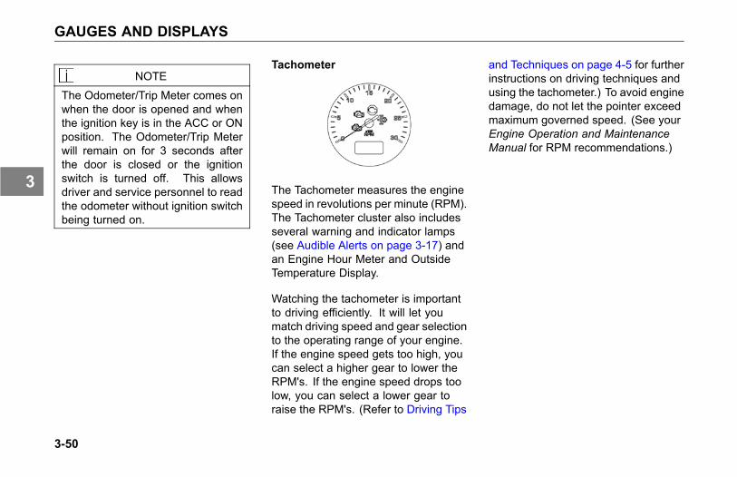
GAUGES AND DISPLAYS
NOTE
The Odometer/Trip Meter comes onwhen the door is opened and whenthe ignition key is in the ACC or ONposition. The Odometer/Trip Meterwill remain on for 3 seconds afterthe door is closed or the ignitionswitch is turned off. This allowsdriver and service personnel to readthe odometer without ignition switchbeing turned on.
Tachometer
The Tachometer measures the enginespeed in revolutions per minute (RPM).The Tachometer cluster also includesseveral warning and indicator lamps(see Audible Alerts on page 3-17) andan Engine Hour Meter and OutsideTemperature Display.
Watching the tachometer is importantto driving efficiently. It will let youmatch driving speed and gear selectionto the operating range of your engine.If the engine speed gets too high, youcan select a higher gear to lower theRPM's. If the engine speed drops toolow, you can select a lower gear toraise the RPM's. (Refer to Driving Tips
and Techniques on page 4-5 for furtherinstructions on driving techniques andusing the tachometer.) To avoid enginedamage, do not let the pointer exceedmaximum governed speed. (See yourEngine Operation and MaintenanceManual for RPM recommendations.)
3-50
3
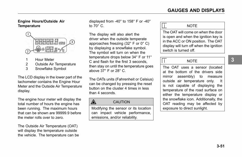
GAUGES AND DISPLAYS
Engine Hours/Outside AirTemperature
1 Hour Meter2 Outside Air Temperature3 Snowflake Symbol
The LCD display in the lower part of thetachometer contains the Engine HourMeter and the Outside Air Temperaturedisplay.
The engine hour meter will display thetotal number of hours the engine hasbeen running. The maximum hoursthat can be shown are 99999.9 beforethe meter rolls over to zero.
The Outside Air Temperature (OAT)will display the temperature outsidethe vehicle. The temperature can be
displayed from -40° to 158° F or -40°to 70° C.
The display will also alert thedriver when the outside temperateapproaches freezing (32° F or 0° C)by displaying a snowflake symbol.The symbol will turn on when thetemperature drops below 34° F or 11°C and flash for the first 3 seconds,then stay on until the temperature goesabove 37° F or 28° C.
The OATs units (Fahrenheit or Celsius)can be changed by pressing the resetbutton on the cluster 4 times in lessthan 4 seconds.
CAUTION
Modifying the sensor or its locationcan impact vehicle performance,emissions, and/or reliability.
NOTE
The OAT will come on when the dooris open and when the ignition key isin the ACC or ON position. The OATdisplay will turn off when the ignitionswitch is turned off.
NOTE
The OAT uses a sensor (locatedat the bottom of the drivers sidemirror assembly) to measureoutside air temperature only. Itis not capable of displaying thetemperature of the road surface oneither the temperature display orthe snowflake icon. Additionally, theOAT reading may be affected byexposure to direct sunlight.
3-51
3

GAUGES AND DISPLAYS
1. Air Filter Restriction Pressure
The Air Filter Restriction Pressuregauge indicates the condition of theengine air cleaner and is measured byinches of water (H2O). A clean filtershould register 7 in. H2O (may varywith system design) and a filter whoselife is over will register approximately20 in. H2O. The red light will come onwhen it has reached a critical level.
CAUTION
Continued operation with the AirFilter Restriction Gauge reading20 in. H2O may cause damage tothe engine. Inspect the filter andreplace if necessary. Holes in thepaper element render an air cleaneruseless and may cause the Air FilterRestriction Gauge to give a falsereading, whether the element isclogged or not. Replace the elementif it is damaged. Failure to complymay result in equipment damage.
2. Ammeter
The ammeter tells you whether thevehicle batteries are being charged bythe alternator or discharging. Positivereading indicates the batteries arecharging, negative reading indicatesthe batteries are discharging.
Under normal conditions the ammeterwill read nearly "zero". If it beginsto read noticeably above or belowthe "zero" balance, have the systemchecked out immediately. If you do not,you could have a roadside breakdown.
3-52
3
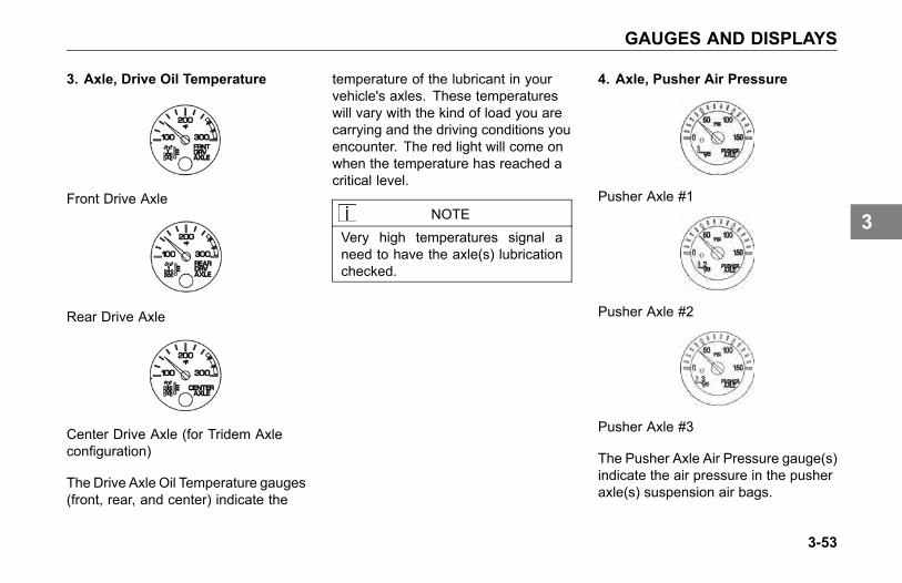
GAUGES AND DISPLAYS
3. Axle, Drive Oil Temperature
Front Drive Axle
Rear Drive Axle
Center Drive Axle (for Tridem Axleconfiguration)
The Drive Axle Oil Temperature gauges(front, rear, and center) indicate the
temperature of the lubricant in yourvehicle's axles. These temperatureswill vary with the kind of load you arecarrying and the driving conditions youencounter. The red light will come onwhen the temperature has reached acritical level.
NOTEVery high temperatures signal aneed to have the axle(s) lubricationchecked.
4. Axle, Pusher Air Pressure
Pusher Axle #1
Pusher Axle #2
Pusher Axle #3
The Pusher Axle Air Pressure gauge(s)indicate the air pressure in the pusheraxle(s) suspension air bags.
3-53
3

GAUGES AND DISPLAYS
5. Axle, Tag Air Pressure
The Tag Axle Air Pressure gaugeindicates the amount of air pressure inthe tag axle suspension air bags.
6. Brake, Application Air Pressure
The Brake Application air gaugeindicates how much air pressure isbeing applied from the foot brake valveor trailer brake hand valve to the airbrakes.
7. Diesel Exhaust Fluid (DEF)
The Diesel Exhaust Fluid gaugeindicates the total (approximate)amount of DEF in the tank. In additionto indicating empty and full, thegauge also indicates the DEF level ingraduated increments. When the DEFlevel in the tank reaches 10% full, a redwarning light in the gauge illuminates,when the DEF level in the tank reaches5%, the red light flashes. Refer toyour PACCAR Engine After-TreatmentControl Operator’s Manual for moreinformation.
3-54
3
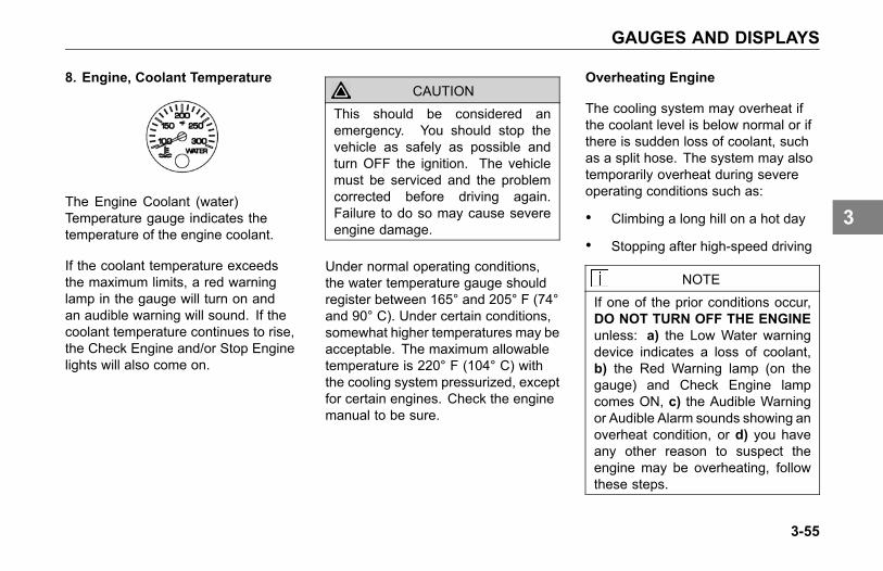
GAUGES AND DISPLAYS
8. Engine, Coolant Temperature
The Engine Coolant (water)Temperature gauge indicates thetemperature of the engine coolant.
If the coolant temperature exceedsthe maximum limits, a red warninglamp in the gauge will turn on andan audible warning will sound. If thecoolant temperature continues to rise,the Check Engine and/or Stop Enginelights will also come on.
CAUTIONThis should be considered anemergency. You should stop thevehicle as safely as possible andturn OFF the ignition. The vehiclemust be serviced and the problemcorrected before driving again.Failure to do so may cause severeengine damage.
Under normal operating conditions,the water temperature gauge shouldregister between 165° and 205° F (74°and 90° C). Under certain conditions,somewhat higher temperatures may beacceptable. The maximum allowabletemperature is 220° F (104° C) withthe cooling system pressurized, exceptfor certain engines. Check the enginemanual to be sure.
Overheating Engine
The cooling system may overheat ifthe coolant level is below normal or ifthere is sudden loss of coolant, suchas a split hose. The system may alsotemporarily overheat during severeoperating conditions such as:
• Climbing a long hill on a hot day
• Stopping after high-speed driving
NOTE
If one of the prior conditions occur,DO NOT TURN OFF THE ENGINEunless: a) the Low Water warningdevice indicates a loss of coolant,b) the Red Warning lamp (on thegauge) and Check Engine lampcomes ON, c) the Audible Warningor Audible Alarm sounds showing anoverheat condition, or d) you haveany other reason to suspect theengine may be overheating, followthese steps.
3-55
3
GAUGES AND DISPLAYS
1. Reduce engine speed or stop.When stopped, place thetransmission in Neutral and setthe parking brake. (Refer to Usingthe Parking Brake on page 4-20and Putting the Vehicle in Motionon page 4-65.)
2. Check to ensure the Oil PressureGauge reads normal. (See theEngine Oil Pressure in Gaugesand Displays on page 3-45, forfurther information.)
3. Make sure the engine fan isturned on by switching the EngineFan Switch from AUTO to MAN(Manual).
4. Increase the engine speed to aboutone-half of full operating speed, or1,100 to 1,200, maximum.
5. Return the engine speed to normalidle after 2 or 3 minutes.
6. Monitor the engine temperature.After the temperature returns to
normal, allow the engine to idle3 to 5 minutes before shutting itoff. This allows the engine to coolgradually and uniformly.
7. If overheating came fromsevere operating conditions, thetemperature should have cooledby this time. If it has not, stopthe engine and let it cool beforechecking to see if the coolant islow.
° Wait until the coolanttemperature is below 122° F(50° C).
° Protect face, hands, and armsby covering the cap with alarge, thick rag to protectagainst escaping fluid andsteam.
° Carefully and slowly turn thecap one-quarter of a turn oruntil it reaches the first stop.
° Allow excess pressure toescape, then push down andturn for final removal.
For further information on enginetemperature and operating enginesproperly, see the Engine Operationand Maintenance Manual. Checkthe coolant level after each trip whenthe engine has cooled. The coolantlevel should be visible within the sightgauge (glass level indicator) on thesurge tank; add coolant if necessary.(Refer to Topping Up on page 5-60, forinstructions on checking and filling thecoolant expansion tank.)
WARNING
Do not remove the radiator fill capwhile the engine is hot. Scaldingsteam and fluid under pressure mayescape. You could be badly burned.Failure to comply may result inpersonal injury or death.
3-56
3
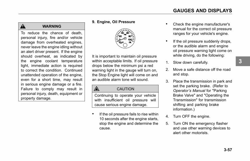
GAUGES AND DISPLAYS
WARNING
To reduce the chance of death,personal injury, fire and/or vehicledamage from overheated engines,never leave the engine idling withoutan alert driver present. If the engineshould overheat, as indicated bythe engine coolant temperaturelight, immediate action is requiredto correct the condition. Continuedunattended operation of the engine,even for a short time, may resultin serious engine damage or a fire.Failure to comply may result inpersonal injury, death, equipment orproperty damage.
9. Engine, Oil Pressure
It is important to maintain oil pressurewithin acceptable limits. If oil pressuredrops below the minimum psi a redwarning light in the gauge will turn on,the Stop Engine light will come on andan audible alarm tone will sound.
CAUTION
Continuing to operate your vehiclewith insufficient oil pressure willcause serious engine damage.
• If the oil pressure fails to rise within10 seconds after the engine starts,stop the engine and determine thecause.
• Check the engine manufacturer'smanual for the correct oil pressureranges for your vehicle's engine.
• If the oil pressure suddenly drops,or the audible alarm and engineoil pressure warning light come onwhile driving, do the following:
1. Slow down carefully.
2. Move a safe distance off the roadand stop.
3. Place the transmission in park andset the parking brake. (Refer toOperator’s Manual for "ParkingBrake Valve" and "Operating theTransmission" for transmissionshifting and parking brakeinformation.)
4. Turn OFF the engine.
5. Turn ON the emergency flasherand use other warning devices toalert other motorists.
3-57
3
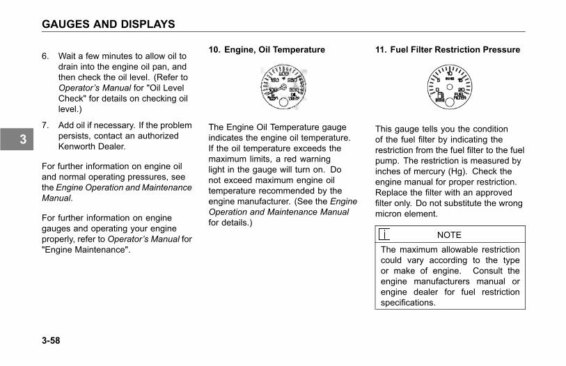
GAUGES AND DISPLAYS
6. Wait a few minutes to allow oil todrain into the engine oil pan, andthen check the oil level. (Refer toOperator’s Manual for "Oil LevelCheck" for details on checking oillevel.)
7. Add oil if necessary. If the problempersists, contact an authorizedKenworth Dealer.
For further information on engine oiland normal operating pressures, seethe Engine Operation and MaintenanceManual.
For further information on enginegauges and operating your engineproperly, refer to Operator’s Manual for"Engine Maintenance".
10. Engine, Oil Temperature
The Engine Oil Temperature gaugeindicates the engine oil temperature.If the oil temperature exceeds themaximum limits, a red warninglight in the gauge will turn on. Donot exceed maximum engine oiltemperature recommended by theengine manufacturer. (See the EngineOperation and Maintenance Manualfor details.)
11. Fuel Filter Restriction Pressure
This gauge tells you the conditionof the fuel filter by indicating therestriction from the fuel filter to the fuelpump. The restriction is measured byinches of mercury (Hg). Check theengine manual for proper restriction.Replace the filter with an approvedfilter only. Do not substitute the wrongmicron element.
NOTEThe maximum allowable restrictioncould vary according to the typeor make of engine. Consult theengine manufacturers manual orengine dealer for fuel restrictionspecifications.
3-58
3

GAUGES AND DISPLAYS
12. Fuel Level, PrimarySecondary (if equipped)
The Primary Fuel gauge andSecondary Fuel gauge (if equipped)indicate the total (approximate) amountof fuel in each fuel tank. In addition toindicating empty and full, the gauge(s)also indicate the fuel level in graduatedincrements. When the fuel level foreach tank is below 1/4 full, a redwarning light in the gauge will come on.
Primary
Secondary
NOTE
For Export vehicles, the fuel gaugeswill not state: ULTRA LOWSULFURDIESEL FUEL ONLY.
NOTE
Kenworth manufactures vehiclesthat are built with different fuelsystems and draw tube locations.Because of this and the amountof road crown, it is recommendedthat you do not operate your vehiclewith less than one-quarter of yourtruck’s fuel capacity. Allowing thefuel level to go below one-quarter ofcapacity could result in the lack offuel to keep the engine running. Inaddition, you will want to keep thefuel tanks at least half-full to reducecondensation of moisture in thetanks. This moisture can damagethe engine.
WARNING
Do not carry fuel containers or anycontainer used to store combustibleliquids. Failure to comply may resultin personal injury, death, equipmentor property damage.
WARNING
Do not remove a fuel tank cap nearan open flame. Fuel vapors maybe hot and combustible and cancause an explosion or fire. Failureto comply may result in personalinjury, death, equipment or propertydamage.
Refer to Refueling on page 4-74 formore information.
3-59
3
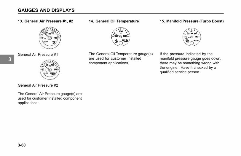
GAUGES AND DISPLAYS
13. General Air Pressure #1, #2
General Air Pressure #1
General Air Pressure #2
The General Air Pressure gauge(s) areused for customer installed componentapplications.
14. General Oil Temperature
The General Oil Temperature gauge(s)are used for customer installedcomponent applications.
15. Manifold Pressure (Turbo Boost)
If the pressure indicated by themanifold pressure gauge goes down,there may be something wrong withthe engine. Have it checked by aqualified service person.
3-60
3

GAUGES AND DISPLAYS
16. Primary and Secondary AirPressure
Primary Air Pressure
Secondary Air Pressure
The Primary Air Pressure gaugeindicates pressure in the rear brakingsystem. The Secondary gaugeindicates pressure in the front brakingsystem. Each gauge indicates theamount of air pressure in each systemin pounds per square inch (psi).
On vehicles equipped with metric airpressure gauges, the gauge face plateincludes a kPa (major) scale and psi(minor) scale.
NOTEBe sure the air pressure registersmore than 100 psi in both servicesystems before you move thevehicle.
NOTE
If the pressure in either or bothcircuits falls below 65 psi, a redwarning light in the gauge will turnon and an audible alarm tone willsound when the engine is running.
WARNING
If the air pressure falls below 60psi (414 kPa), the spring brakesmay stop the vehicle abruptly whichcould cause an accident resulting inpersonal injury or death. Observethe red warning lamps on thegauges. If one comes on, do notcontinue to drive the vehicle untilit has been properly repaired orserviced.
3-61
3
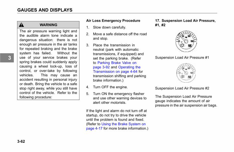
GAUGES AND DISPLAYS
WARNING
The air pressure warning light andthe audible alarm tone indicate adangerous situation: there is notenough air pressure in the air tanksfor repeated braking and the brakesystem has failed. Without theuse of your service brakes yourspring brakes could suddenly applycausing a wheel lock-up, loss ofcontrol, or over-take by followingvehicles. This may cause anaccident resulting in personal injuryor death. Bring the vehicle to a safestop right away, while you still havecontrol of the vehicle. Refer to thefollowing procedure:
Air Loss Emergency Procedure
1. Slow down carefully.
2. Move a safe distance off the roadand stop.
3. Place the transmission inneutral (park with automatictransmissions, if equipped) andset the parking brake. (Referto Parking Brake Valve onpage 3-92 and Operating theTransmission on page 4-64 fortransmission shifting and parkingbrake information.)
4. Turn OFF the engine.
5. Turn ON the emergency flasherand use other warning devices toalert other motorists.
If the light and alarm do not turn off atstartup, do not try to drive the vehicleuntil the problem is found and fixed.(Refer to Using the Brake System onpage 4-17 for more brake information.)
17. Suspension Load Air Pressure,#1, #2
Suspension Load Air Pressure #1
Suspension Load Air Pressure #2
The Suspension Load Air Pressuregauge indicates the amount of airpressure in the air suspension air bags.
3-62
3
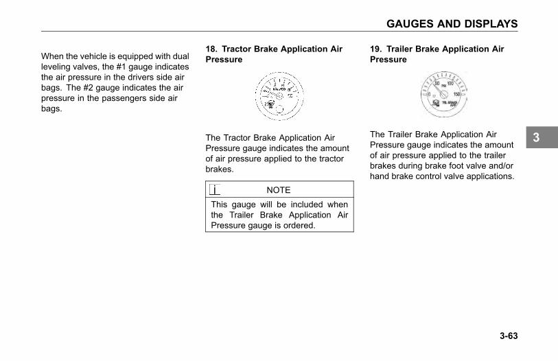
GAUGES AND DISPLAYS
When the vehicle is equipped with dualleveling valves, the #1 gauge indicatesthe air pressure in the drivers side airbags. The #2 gauge indicates the airpressure in the passengers side airbags.
18. Tractor Brake Application AirPressure
The Tractor Brake Application AirPressure gauge indicates the amountof air pressure applied to the tractorbrakes.
NOTEThis gauge will be included whenthe Trailer Brake Application AirPressure gauge is ordered.
19. Trailer Brake Application AirPressure
The Trailer Brake Application AirPressure gauge indicates the amountof air pressure applied to the trailerbrakes during brake foot valve and/orhand brake control valve applications.
3-63
3
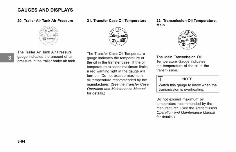
GAUGES AND DISPLAYS
20. Trailer Air Tank Air Pressure
The Trailer Air Tank Air Pressuregauge indicates the amount of airpressure in the trailer brake air tank.
21. Transfer Case Oil Temperature
The Transfer Case Oil Temperaturegauge indicates the temperature ofthe oil in the transfer case. If the oiltemperature exceeds maximum limits,a red warning light in the gauge willturn on. Do not exceed maximumoil temperature recommended by themanufacturer. (See the Transfer CaseOperation and Maintenance Manualfor details.)
22. Transmission Oil Temperature,Main
The Main Transmission OilTemperature Gauge indicatesthe temperature of the oil in thetransmission.
NOTEWatch this gauge to know when thetransmission is overheating.
Do not exceed maximum oiltemperature recommended by themanufacturer. (See the TransmissionOperation and Maintenance Manualfor details.)
3-64
3
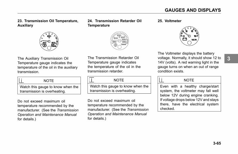
GAUGES AND DISPLAYS
23. Transmission Oil Temperature,Auxiliary
The Auxiliary Transmission OilTemperature gauge indicates thetemperature of the oil in the auxiliarytransmission.
NOTEWatch this gauge to know when thetransmission is overheating.
Do not exceed maximum oiltemperature recommended by themanufacturer. (See the TransmissionOperation and Maintenance Manualfor details.)
24. Transmission Retarder OilTemperature
The Transmission Retarder OilTemperature gauge indicatesthe temperature of the oil in thetransmission retarder.
NOTEWatch this gauge to know when thetransmission is overheating.
Do not exceed maximum oiltemperature recommended by themanufacturer. (See the TransmissionOperation and Maintenance Manualfor details.)
25. Voltmeter
The Voltmeter displays the batteryvoltage. Normally, it should show 12 to14V (volts). A red warning light in thegauge turns on when an out of rangecondition exists.
NOTE
Even with a healthy charge/startsystem, the voltmeter may fall wellbelow 12V during engine cranking.If voltage drops below 12V and staysthere, have the electrical systemchecked.
3-65
3

MULTI-FUNCTION DISPLAY
MULTI-FUNCTIONDISPLAY
Introduction
This section explains the location andfunction of the various instruments andcontrols on your vehicle.
Please remember that each Kenworthis custom made. Your instrument panelmay not look exactly like the one inthe illustration below. Described beloware the most common instruments andcontrols available.
Alarms, Warning Tones andVisual Indicator LightsIntroduction
Your vehicle's dash andinstrumentation uses variousmethods to indicate to you the statusof various systems, or that one ormore of your vehicle's systems maybe malfunctioning. The methodto communicate or alert you of aparticular condition is by:
• Audible alarm tone
• Audible warning tone
• Indicator light(s)
In some cases, you may have both analarm or warning tone accompanied byan indicator light(s).
WARNING
Do not ignore any type of toneor lights. These signals tell youthat something is malfunctioning onyour vehicle and provide you anindication of what system is affected.It could be a failure of an importantsystem, such as the brakes, whichcould lead to an accident and mayresult in personal injury, death,equipment or property damage.
3-66
3

MULTI-FUNCTION DISPLAY
Warning and InformationAlert Screens
The Multi-Function display has variousalert screens that are either warnings,or informational.
No Idle Shutdown
The No-Idle Shutdown screen isactivated upon engine shutdown dueto extended idle time while not moving.
Cruise Control Rationality(Brake/Clutch)
The Cruise Control Rationality screenis displayed when attempting toactivate the cruise control prior todepressing both the service brakepedal and the clutch pedal. Forvehicles with automated transmissionsand no clutch pedal, only the servicebrake pedal needs to be depressed.
Park Brake On While Moving
The Park Brake On While Movingwarning screen is displayed whenthe Park Brake is on and the vehiclespeed is greater than zero and/or theaccelerator pedal position is greaterthan 10%.
Lamp Faults - Low/High Beam
The Lamp Faults screen is displayedwhen an error is detected in theheadlamp circuits.
Regen Inhibited
The Regen Inhibited due toSwitch screen is displayed whena regeneration is required and the DPFswitch is in the inhibit position.
3-67
3

MULTI-FUNCTION DISPLAY
DEF (Low Diesel Exhaust Fluid)
The DEF Warning screen is displayedwhen the DEF Fluid level has reacheda critically low level. It may besuppressed by pushing enter on theMCS (Menu Control Switch). SeeMenu Control Switch on page 3-76.This warning may be accompanied bythe DEF Level in the low range, DEFLamp on solid or flashing, the CheckEngine lamp, the Stop Engine lamp,the MIL lamp, and/or engine de-rate.
SCR/DEF
The Exhaust (SCR/DEF) ServiceRequired screen is displayed wheneither the SCR system has beentampered with or the DEF qualityis below standards. It may besuppressed by pushing enter on theMCS (Menu Control Switch). SeeMenu Control Switch on page 3-76.This warning may be accompaniedby the DEF Lamp flashing, the CheckEngine lamp, the Stop Engine lamp,the MIL lamp, and/or engine de-rate.
Trailer Fault
The Trailer Fault screen is displayedwhen an error is detected in the trailercircuits.
Low Voltage Disconnect
The Low Voltage Disconnect (LVD)screen is displayed when the systemvoltage falls to 12.1 volts.
Over-Crank Protection
Over-Crank Protection screen isdisplayed when the starter motor isbeing protected from over heat or frombeing engaged while the engine isrunning.
3-68
3
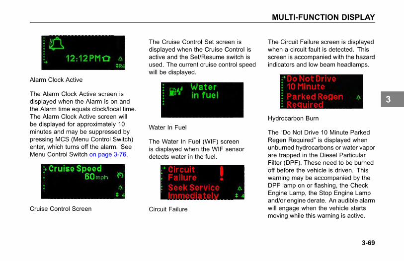
MULTI-FUNCTION DISPLAY
Alarm Clock Active
The Alarm Clock Active screen isdisplayed when the Alarm is on andthe Alarm time equals clock/local time.The Alarm Clock Active screen willbe displayed for approximately 10minutes and may be suppressed bypressing MCS (Menu Control Switch)enter, which turns off the alarm. SeeMenu Control Switch on page 3-76.
Cruise Control Screen
The Cruise Control Set screen isdisplayed when the Cruise Control isactive and the Set/Resume switch isused. The current cruise control speedwill be displayed.
Water In Fuel
The Water In Fuel (WIF) screenis displayed when the WIF sensordetects water in the fuel.
Circuit Failure
The Circuit Failure screen is displayedwhen a circuit fault is detected. Thisscreen is accompanied with the hazardindicators and low beam headlamps.
Hydrocarbon Burn
The “Do Not Drive 10 Minute ParkedRegen Required” is displayed whenunburned hydrocarbons or water vaporare trapped in the Diesel ParticularFilter (DPF). These need to be burnedoff before the vehicle is driven. Thiswarning may be accompanied by theDPF lamp on or flashing, the CheckEngine Lamp, the Stop Engine Lampand/or engine derate. An audible alarmwill engage when the vehicle startsmoving while this warning is active.
3-69
3
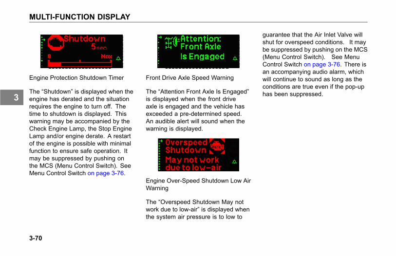
MULTI-FUNCTION DISPLAY
Engine Protection Shutdown Timer
The “Shutdown” is displayed when theengine has derated and the situationrequires the engine to turn off. Thetime to shutdown is displayed. Thiswarning may be accompanied by theCheck Engine Lamp, the Stop EngineLamp and/or engine derate. A restartof the engine is possible with minimalfunction to ensure safe operation. Itmay be suppressed by pushing onthe MCS (Menu Control Switch). SeeMenu Control Switch on page 3-76.
Front Drive Axle Speed Warning
The “Attention Front Axle Is Engaged”is displayed when the front driveaxle is engaged and the vehicle hasexceeded a pre-determined speed.An audible alert will sound when thewarning is displayed.
Engine Over-Speed Shutdown Low AirWarning
The “Overspeed Shutdown May notwork due to low-air” is displayed whenthe system air pressure is to low to
guarantee that the Air Inlet Valve willshut for overspeed conditions. It maybe suppressed by pushing on the MCS(Menu Control Switch). See MenuControl Switch on page 3-76. There isan accompanying audio alarm, whichwill continue to sound as long as theconditions are true even if the pop-uphas been suppressed.
3-70
3
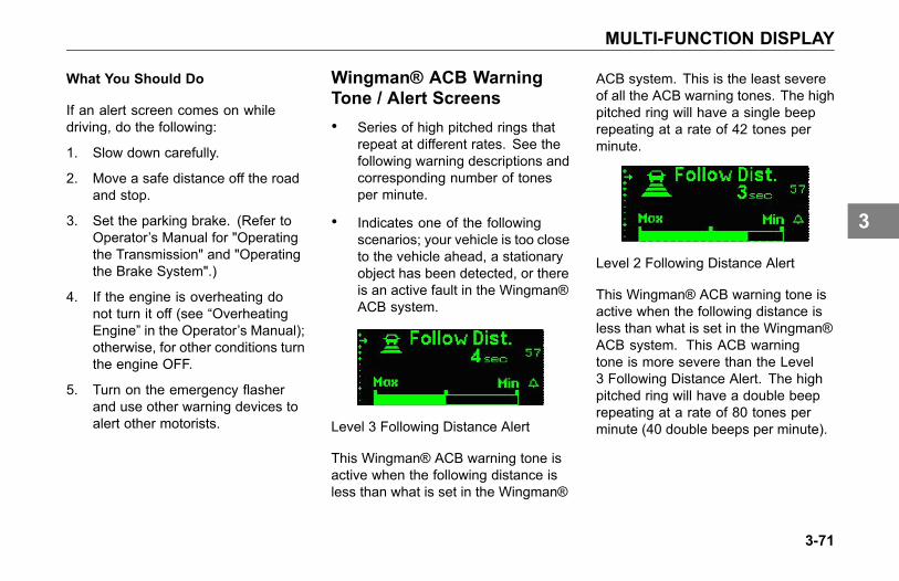
MULTI-FUNCTION DISPLAY
What You Should Do
If an alert screen comes on whiledriving, do the following:
1. Slow down carefully.
2. Move a safe distance off the roadand stop.
3. Set the parking brake. (Refer toOperator’s Manual for "Operatingthe Transmission" and "Operatingthe Brake System".)
4. If the engine is overheating donot turn it off (see “OverheatingEngine” in the Operator’s Manual);otherwise, for other conditions turnthe engine OFF.
5. Turn on the emergency flasherand use other warning devices toalert other motorists.
Wingman® ACB WarningTone / Alert Screens• Series of high pitched rings that
repeat at different rates. See thefollowing warning descriptions andcorresponding number of tonesper minute.
• Indicates one of the followingscenarios; your vehicle is too closeto the vehicle ahead, a stationaryobject has been detected, or thereis an active fault in the Wingman®ACB system.
Level 3 Following Distance Alert
This Wingman® ACB warning tone isactive when the following distance isless than what is set in the Wingman®
ACB system. This is the least severeof all the ACB warning tones. The highpitched ring will have a single beeprepeating at a rate of 42 tones perminute.
Level 2 Following Distance Alert
This Wingman® ACB warning tone isactive when the following distance isless than what is set in the Wingman®ACB system. This ACB warningtone is more severe than the Level3 Following Distance Alert. The highpitched ring will have a double beeprepeating at a rate of 80 tones perminute (40 double beeps per minute).
3-71
3
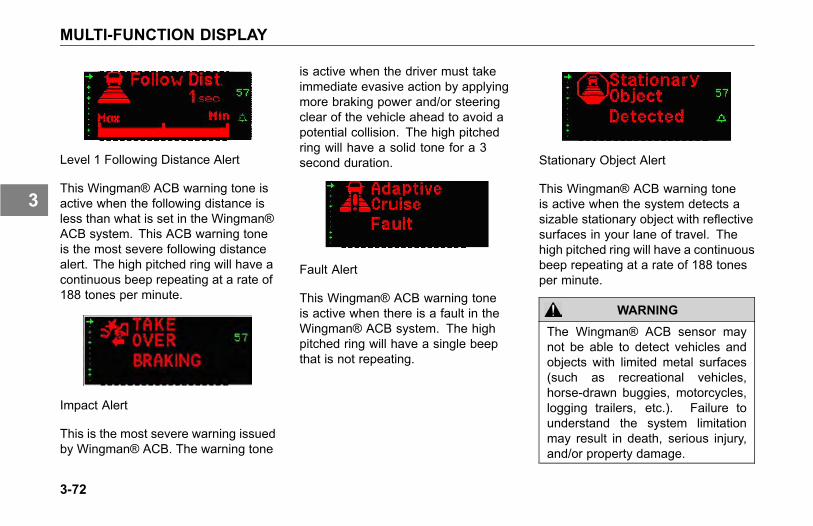
MULTI-FUNCTION DISPLAY
Level 1 Following Distance Alert
This Wingman® ACB warning tone isactive when the following distance isless than what is set in the Wingman®ACB system. This ACB warning toneis the most severe following distancealert. The high pitched ring will have acontinuous beep repeating at a rate of188 tones per minute.
Impact Alert
This is the most severe warning issuedby Wingman® ACB. The warning tone
is active when the driver must takeimmediate evasive action by applyingmore braking power and/or steeringclear of the vehicle ahead to avoid apotential collision. The high pitchedring will have a solid tone for a 3second duration.
Fault Alert
This Wingman® ACB warning toneis active when there is a fault in theWingman® ACB system. The highpitched ring will have a single beepthat is not repeating.
Stationary Object Alert
This Wingman® ACB warning toneis active when the system detects asizable stationary object with reflectivesurfaces in your lane of travel. Thehigh pitched ring will have a continuousbeep repeating at a rate of 188 tonesper minute.
WARNING
The Wingman® ACB sensor maynot be able to detect vehicles andobjects with limited metal surfaces(such as recreational vehicles,horse-drawn buggies, motorcycles,logging trailers, etc.). Failure tounderstand the system limitationmay result in death, serious injury,and/or property damage.
3-72
3
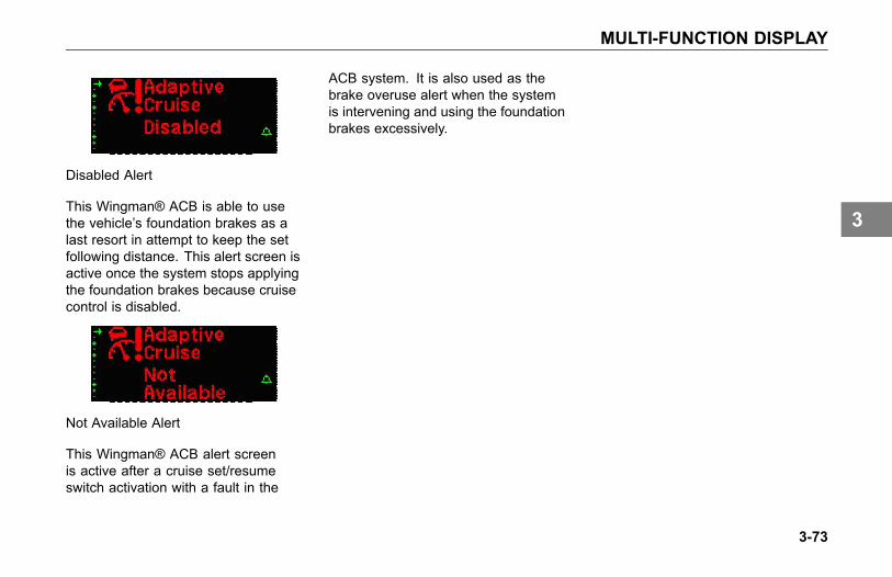
MULTI-FUNCTION DISPLAY
Disabled Alert
This Wingman® ACB is able to usethe vehicle’s foundation brakes as alast resort in attempt to keep the setfollowing distance. This alert screen isactive once the system stops applyingthe foundation brakes because cruisecontrol is disabled.
Not Available Alert
This Wingman® ACB alert screenis active after a cruise set/resumeswitch activation with a fault in the
ACB system. It is also used as thebrake overuse alert when the systemis intervening and using the foundationbrakes excessively.
3-73
3

MULTI-FUNCTION DISPLAY
Multi-Function Display
1 Multi-Function Display
WARNING
Do not look at the Multi-FunctionDisplay for prolonged periods whilethe vehicle is moving. Only glanceat the monitor briefly while driving.Failure to do so can result inthe driver not being attentive tothe vehicle's road position, whichcould lead to an accident involvingpersonal injury, death or vehicledamage.
The Multi-Function Display integratesthe following list of functions (menuitems) into one display.
• Blank Screen (for night driving)
• Engine RPM Display
• Fuel Economy Display
• Ignition Timer
• Trip Information Display
• Truck Information Display
• On-Board Diagnostic Display
• Transmission Gear Display(automated transmissions only)
• Clock Display
• Collision Avoidance
• Settings Screen
The Multi-Function Display, locatedabove the primary instrument
cluster will display important vehicleinformation through a constant monitorof systems. The display will turn onwhenever one of the following areactivated:
• Ignition key is in ON or ACCpositions
• Ignition timer is ON (active)
• MCS button is pushed(independent of ignition keyswitch position)
• Clock alarm sounds
• Driver or passenger door isopened
• Hazard warning lamp switch is ON
• Head lamp switch is ON
• Dome lamp switch is ON
• Service Brake switch is ON
3-74
3
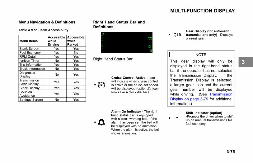
MULTI-FUNCTION DISPLAY
Menu Navigation & Definitions
Table 4 Menu Item Accessibility
Menu ItemsAccessiblewhileDriving
AccessiblewhileParked
Blank Screen Yes YesFuel Economy Yes NoRPM Detail Yes YesIgnition Timer No YesTrip Information Yes YesTruck Information No YesDiagnosticDisplay No Yes
TransmissionGear Display Yes Yes
Clock Display Yes YesCollisionAvoidance Yes Yes
Settings Screen No Yes
Right Hand Status Bar andDefinitions
Right Hand Status Bar
●
Cruise Control Active - Iconwill indicate when cruise controlis active or the cruise set speedwill be displayed (optional). Iconlooks like a clock dial face.
●
Alarm On Indicator - The righthand status bar is equippedwith a clock warning bell. If thealarm has been set, the bell willbe displayed with no animation.When the alarm is active, the bellshows animation.
●Gear Display (for automatictransmissions only) - Displayspresent gear.
NOTEThis gear display will only bedisplayed in the right-hand statusbar if the operator has not selectedthe Transmission Display. If theTransmission Display is selected,a larger gear icon and the currentgear number will be displayedwhile driving. (See TransmissionDisplay on page 3-79 for additionalinformation.)
●Shift Indicator (option)-Prompts the driver when to shiftup on manual transmissions forfuel economy.
3-75
3

MULTI-FUNCTION DISPLAY
Left Hand Menu Bar
The left hand menu bar (menu bullets)gives the status of the current menuitem. Scroll through the menu itemsby rotating the Menu Control Switch(MCS) clockwise (down the menu)or counterclockwise (up the menu).Select a menu item by pressing theMCS. Some menu items requirethe MCS to be pressed to accessSubmenu information.
1 Menu Control Switch (MCS)2 Heater and Air Conditioning
Controls
Menu Items
A. Blank Screen - No information orgraphics displayed.
B. Fuel Economy
Fuel Economy
1. Bar graph - Indicatesinstantaneous fuel economy.
2. Trip Econ. - Indicates trip fueleconomy.
C. RPM Detail
RPM
RPM reading of actual engine RPM.Engine RPM within the bar graphchevrons (in range zone) indicates theengine is operating in the most efficientRPM range.
3-76
3
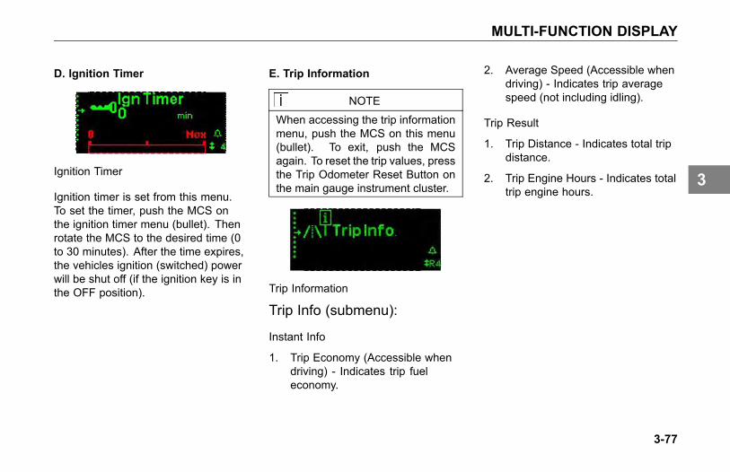
MULTI-FUNCTION DISPLAY
D. Ignition Timer
Ignition Timer
Ignition timer is set from this menu.To set the timer, push the MCS onthe ignition timer menu (bullet). Thenrotate the MCS to the desired time (0to 30 minutes). After the time expires,the vehicles ignition (switched) powerwill be shut off (if the ignition key is inthe OFF position).
E. Trip Information
NOTE
When accessing the trip informationmenu, push the MCS on this menu(bullet). To exit, push the MCSagain. To reset the trip values, pressthe Trip Odometer Reset Button onthe main gauge instrument cluster.
Trip Information
Trip Info (submenu):
Instant Info
1. Trip Economy (Accessible whendriving) - Indicates trip fueleconomy.
2. Average Speed (Accessible whendriving) - Indicates trip averagespeed (not including idling).
Trip Result
1. Trip Distance - Indicates total tripdistance.
2. Trip Engine Hours - Indicates totaltrip engine hours.
3-77
3
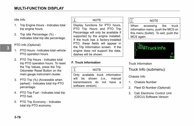
MULTI-FUNCTION DISPLAY
Idle Info
1. Trip Engine Hours - Indicates totaltrip engine hours.
2. Trip Idle Percentage (%) -Indicates total trip idle percentage.
PTO Info (Optional)
1. PTO Hours - Indicates total vehiclePTO operation hours.
2. PTO Trip Hours - Indicates totaltrip PTO operation hours. To resetthe Trip Values, press the TripOdometer Reset Button on themain gauge instrument cluster.
3. PTO Trip (%) (Accessible whenparked) - Indicates total trip PTOpercentage.
4. PTO Trip Fuel - Indicates total tripPTO fuel.
5. PTO Trip Economy - Indicatestotal trip PTO economy.
NOTE
Display functions for PTO hours,PTO Trip Hours and PTO TripPercentage will only be available ifsupported by the engine installed.If the truck has a factory-installedPTO, these fields will appear inthe Trip Information screen. If theengine does not support the data,dashes will be shown.
F. Truck Information
NOTE
Only available truck informationwill be shown (i.e., manualtransmissions do not have asoftware version).
NOTEWhen accessing the truckinformation menu, push the MCS onthis menu (bullet). To exit, push theMCS again.
Truck Information
Truck Info (submenu):
Chassis Info
1. Chassis Number
2. Fleet ID Number (Optional)
3. Cab Electronic Control Unit(CECU) Software Version
3-78
3

MULTI-FUNCTION DISPLAY
Engine Info
1. Engine Make
2. Engine Model
3. Engine Software Version
4. Governed Speed Limit (Optional)
Transmission Info (AutomatedTransmissions only)
1. Transmission Make
2. Transmission Model
3. Transmission Software Version
ABS Info
1. ABS (Anti-Lock Braking System)Make
2. ABS Model
3. ABS Software Version
G. Diagnostic Display
NOTE"Faults Found" will only be activeif a red or yellow warning lampis illuminated and additionalinformation is available.
Diagnostic Display
The diagnostic display menu (bullet)will indicate a fault that is present.While on this menu item the displaywill either indicate "No Faults Found"or "Faults Found". If "Faults Found"is active, pushing the MCS on thismenu item will show "Exit", "Engine","Transmission", "ABS", "Truck", and/or"Soot Filter".
Exit will take you back to the diagnosticmenu bullet and clicking on any ofthe other items will display an activevehicle diagnostic message.
H. Transmission Display (AutomatedTransmissions only)
NOTE
Refer to the AutomatedTransmission Operator's Manualfor complete description of arrowsymbols.
Transmission Display
Shows gear number that coincideswith the current transmission gearselected. Can also indicate to driverto shift up or down.
3-79
3

MULTI-FUNCTION DISPLAY
I. Speed Control ManagementDisplay (Automated Transmissionsonly)
Upshift Indicator while on TransmissionGear Screen with Autoshift or UltrashiftTransmissions
The “Shift for fuel econ.” is displayedwhen the current screen isTransmission Display And theengine requests an upshift for betterfuel economy.
J. Clock Display
Clock Display
Shows Local or Home time as selectedby the driver. The time can also beset to show 12 hour time (AM/PM) or24 hour time (military). Refer to the"Settings Menu" section for additionalinformation covering clock/alarm andformatting options.
K. Settings Menu
The Settings menu screen allowsthe driver to view and/or change thefollowing menu items:
• Clock Display Format 12 Hour(AM/PM) or 24 Hour (military)
• Clock Home/Local Time
• Clock Alarm ON/OFF
• Clock Local Time (Set)
• Clock Alarm Time (Set)
• Trailer Detect
• Headlamps With Wipers
• Units Standard or Metric
• Language English, Spanish orFrench
• Pre-Trip Lamp Test
• Exit
Settings Menu
3-80
3
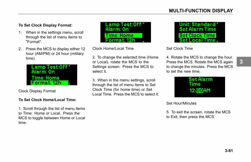
MULTI-FUNCTION DISPLAY
To Set Clock Display Format:
1. When in the settings menu, scrollthrough the list of menu items to"Format".
2. Press the MCS to display either 12hour (AM/PM) or 24 hour (militarytime).
Clock Display Format
To Set Clock Home/Local Time:
1. Scroll through the list of menu itemsto Time: Home or Local. Press theMCS to toggle between Home or Localtime.
Clock Home/Local Time
2. To change the selected time (Homeor Local), rotate the MCS to theSettings screen. Press the MCS toselect it.
3. When in the menu settings, scrollthrough the list of menu items to SetClock Time (for home time) or SetLocal Time. Press the MCS to select it.
Set Clock Time
4. Rotate the MCS to change the hour.Press the MCS. Rotate the MCS againto change the minutes. Press the MCSto set the new time.
Set Hour/Minutes
5. To exit the screen, rotate the MCSto Exit, then press the MCS.
3-81
3
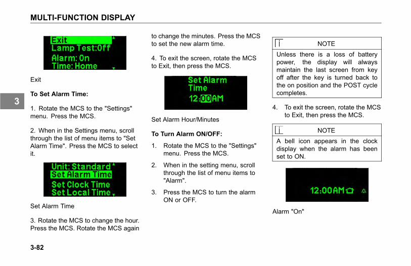
MULTI-FUNCTION DISPLAY
Exit
To Set Alarm Time:
1. Rotate the MCS to the "Settings"menu. Press the MCS.
2. When in the Settings menu, scrollthrough the list of menu items to "SetAlarm Time". Press the MCS to selectit.
Set Alarm Time
3. Rotate the MCS to change the hour.Press the MCS. Rotate the MCS again
to change the minutes. Press the MCSto set the new alarm time.
4. To exit the screen, rotate the MCSto Exit, then press the MCS.
Set Alarm Hour/Minutes
To Turn Alarm ON/OFF:
1. Rotate the MCS to the "Settings"menu. Press the MCS.
2. When in the setting menu, scrollthrough the list of menu items to"Alarm".
3. Press the MCS to turn the alarmON or OFF.
NOTE
Unless there is a loss of batterypower, the display will alwaysmaintain the last screen from keyoff after the key is turned back tothe on position and the POST cyclecompletes.
4. To exit the screen, rotate the MCSto Exit, then press the MCS.
NOTEA bell icon appears in the clockdisplay when the alarm has beenset to ON.
Alarm "On"
3-82
3
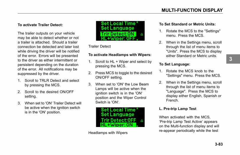
MULTI-FUNCTION DISPLAY
To activate Trailer Detect:
The trailer outputs on your vehiclemay be able to detect whether or nota trailer is attached. Should a trailerconnection be detected and later lostwhile driving the driver will be notifiedof the error. Errors will be presentedto the driver as either intermittent orpersistent depending on the durationof the error. All notifications may besuppressed by the driver.
1. Scroll to TRLR Detect and selectby pressing the MCS.
2. Scroll to the desired ON/OFFsetting.
3. When set to 'ON' Trailer Detect willbe active when the ignition switchis in the 'ON' position.
Trailer Detect
To activate Headlamps with Wipers:
1. Scroll to HL + Wiper and select bypressing the MCS.
2. Press MCS to toggle to the desiredON/OFF setting.
3. When set to 'ON' the Low BeamLamps will be active when theignition switch is in the 'ON'position and the Wiper ControlSwitch is 'ON'.
Headlamps with Wipers
To Set Standard or Metric Units:
1. Rotate the MCS to the "Settings"menu. Press the MCS.
2. When in the Settings menu, scrollthrough the list of menu items to"Units". Press the MCS to displayeither Standard or Metric units.
To Set Language:
1. Rotate the MCS knob to the"Settings" menu. Press the MCS.
2. When in the Settings menu, scrollthrough the list of menu items to"Language". Press the MCS todisplay either English, Spanish orFrench.
L. Pre-trip Lamp Test
When activated with the MCS,‘Pre-trip Lamp Test Active’ appearson the Multi-function display and willre-appear periodically while the test
3-83
3
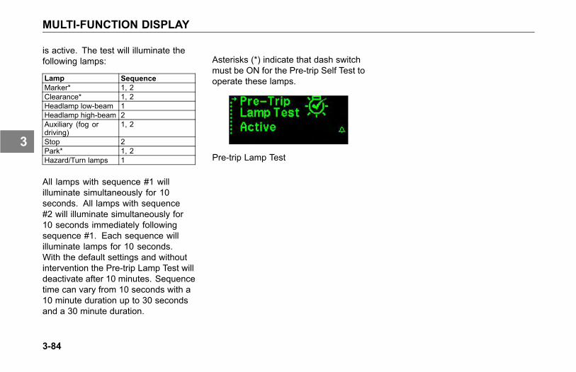
MULTI-FUNCTION DISPLAY
is active. The test will illuminate thefollowing lamps:
Lamp SequenceMarker* 1, 2Clearance* 1, 2Headlamp low-beam 1Headlamp high-beam 2Auxiliary (fog ordriving)
1, 2
Stop 2Park* 1, 2Hazard/Turn lamps 1
All lamps with sequence #1 willilluminate simultaneously for 10seconds. All lamps with sequence#2 will illuminate simultaneously for10 seconds immediately followingsequence #1. Each sequence willilluminate lamps for 10 seconds.With the default settings and withoutintervention the Pre-trip Lamp Test willdeactivate after 10 minutes. Sequencetime can vary from 10 seconds with a10 minute duration up to 30 secondsand a 30 minute duration.
Asterisks (*) indicate that dash switchmust be ON for the Pre-trip Self Test tooperate these lamps.
Pre-trip Lamp Test
3-84
3

SWITCHES
SWITCHES
Introduction
Numbered items in illustration are standard or common switches.
3-85
3
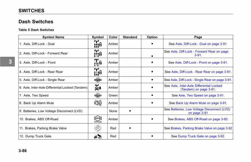
SWITCHES
Dash SwitchesTable 5 Dash Switches
Symbol Name Symbol Color Standard Option Page
1. Axle, Diff-Lock - Dual Amber ● See Axle, Diff-Lock - Dual on page 3-91.
2. Axle, Diff-Lock - Forward Rear Amber●
See Axle, Diff-Lock - Forward Rear on page3-91.
3. Axle, Diff-Lock - Front Amber ● See Axle, Diff-Lock - Front on page 3-91.
4. Axle, Diff-Lock - Rear Rear Amber ● See Axle, Diff-Lock - Rear Rear on page 3-91.
5. Axle, Diff-Lock - Single Rear Amber ● See Axle, Diff-Lock - Single Rear on page 3-91.
6. Axle, Inter-Axle Differential Locked (Tandem) Amber ● See Axle, Inter-Axle Differential Locked(Tandem) on page 3-91.
7. Axle, Two Speed Green ● See Axle, Two Speed on page 3-91.
8. Back Up Alarm Mute Amber ● See Back Up Alarm Mute on page 3-91.
9. Batteries, Low Voltage Disconnect (LVD) None ● See Batteries, Low Voltage Disconnect (LVD)on page 3-91
10. Brakes, ABS Off-Road Amber ● See Brakes, ABS Off-Road on page 3-92.
11. Brakes, Parking Brake Valve Red ● See Brakes, Parking Brake Valve on page 3-92
12. Dump Truck Gate Red ● See Dump Truck Gate on page 3-92.
3-86
3
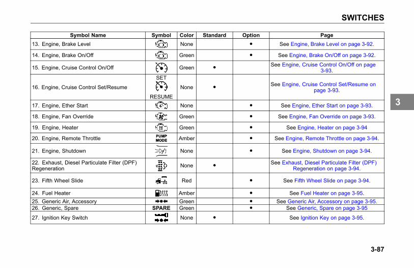
SWITCHES
Symbol Name Symbol Color Standard Option Page13. Engine, Brake Level None ● See Engine, Brake Level on page 3-92.
14. Engine, Brake On/Off Green ● See Engine, Brake On/Off on page 3-92.
15. Engine, Cruise Control On/Off Green ● See Engine, Cruise Control On/Off on page3-93.
16. Engine, Cruise Control Set/Resume
SET
RESUME
None ● See Engine, Cruise Control Set/Resume onpage 3-93.
17. Engine, Ether Start None ● See Engine, Ether Start on page 3-93.
18. Engine, Fan Override Green ● See Engine, Fan Override on page 3-93.
19. Engine, Heater Green ● See Engine, Heater on page 3-94
20. Engine, Remote Throttle Amber ● See Engine, Remote Throttle on page 3-94.
21. Engine, Shutdown None ● See Engine, Shutdown on page 3-94.
22. Exhaust, Diesel Particulate Filter (DPF)Regeneration None ● See Exhaust, Diesel Particulate Filter (DPF)
Regeneration on page 3-94.
23. Fifth Wheel Slide Red ● See Fifth Wheel Slide on page 3-94.
24. Fuel Heater Amber ● See Fuel Heater on page 3-95.25. Generic Air, Accessory Green ● See Generic Air, Accessory on page 3-95.26. Generic, Spare SPARE Green ● See Generic, Spare on page 3-95
27. Ignition Key Switch None ● See Ignition Key on page 3-95.
3-87
3
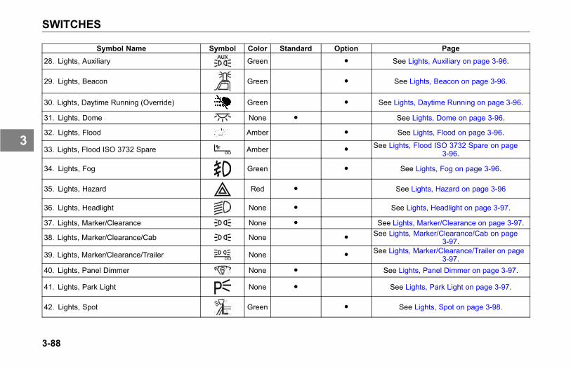
SWITCHES
Symbol Name Symbol Color Standard Option Page
28. Lights, Auxiliary Green ● See Lights, Auxiliary on page 3-96.
29. Lights, Beacon Green ● See Lights, Beacon on page 3-96.
30. Lights, Daytime Running (Override) Green ● See Lights, Daytime Running on page 3-96.
31. Lights, Dome None ● See Lights, Dome on page 3-96.
32. Lights, Flood Amber ● See Lights, Flood on page 3-96.
33. Lights, Flood ISO 3732 Spare Amber ● See Lights, Flood ISO 3732 Spare on page3-96.
34. Lights, Fog Green ● See Lights, Fog on page 3-96.
35. Lights, Hazard Red ● See Lights, Hazard on page 3-96
36. Lights, Headlight None ● See Lights, Headlight on page 3-97.
37. Lights, Marker/Clearance None ● See Lights, Marker/Clearance on page 3-97.
38. Lights, Marker/Clearance/Cab None ● See Lights, Marker/Clearance/Cab on page3-97.
39. Lights, Marker/Clearance/Trailer None ● See Lights, Marker/Clearance/Trailer on page3-97.
40. Lights, Panel Dimmer None ● See Lights, Panel Dimmer on page 3-97.
41. Lights, Park Light None ● See Lights, Park Light on page 3-97.
42. Lights, Spot Green ● See Lights, Spot on page 3-98.
3-88
3
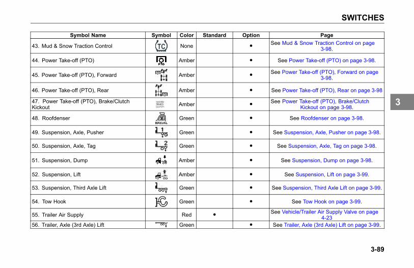
SWITCHES
Symbol Name Symbol Color Standard Option Page
43. Mud & Snow Traction Control None ● See Mud & Snow Traction Control on page3-98.
44. Power Take-off (PTO) Amber ● See Power Take-off (PTO) on page 3-98.
45. Power Take-off (PTO), Forward Amber ● See Power Take-off (PTO), Forward on page3-98.
46. Power Take-off (PTO), Rear Amber ● See Power Take-off (PTO), Rear on page 3-98
47. Power Take-off (PTO), Brake/ClutchKickout Amber ● See Power Take-off (PTO), Brake/Clutch
Kickout on page 3-98.
48. Roofdenser Green ● See Roofdenser on page 3-98.
49. Suspension, Axle, Pusher Green ● See Suspension, Axle, Pusher on page 3-98.
50. Suspension, Axle, Tag Green ● See Suspension, Axle, Tag on page 3-98.
51. Suspension, Dump Amber ● See Suspension, Dump on page 3-98.
52. Suspension, Lift Amber ● See Suspension, Lift on page 3-99.
53. Suspension, Third Axle Lift Green ● See Suspension, Third Axle Lift on page 3-99.
54. Tow Hook Green ● See Tow Hook on page 3-99.
55. Trailer Air Supply Red ● See Vehicle/Trailer Air Supply Valve on page4-23
56. Trailer, Axle (3rd Axle) Lift Green ● See Trailer, Axle (3rd Axle) Lift on page 3-99.
3-89
3

SWITCHES
Symbol Name Symbol Color Standard Option Page
57. Trailer, Axle Lift Forward Green ● See Trailer, Axle Lift Forward on page 3-99.
58. Trailer, Axle Lift Rear Green ● See Trailer, Axle Lift Rear on page 3-99.
59. Trailer, Belly Dump Red ● See Trailer, Belly Dump on page 3-99.
60. Trailer, Dump Gate Red ● See Trailer, Dump Gate on page 3-99.
61. Trailer, Dump Gate Center Red ● See Trailer, Dump Gate Center on page 3-99.62. Trailer, Dump Gate Front Red ● See Trailer, Dump Gate Front on page 3-99.63. Trailer, Dump Gate Rear Red ● See Trailer, Dump Gate Rear on page 3-99.64. Trailer, Hotline Green ● See Trailer, Hotline on page 3-99.
65. Trailer, Suspension Air Dump Amber ● See Trailer, Suspension Air Dump on page3-99
66. Winch Clutch Green ● See Winch Clutch on page 3-99.
67. Trip Odometer Reset Button Odometer/Trip Meter on page 3-49.
3-90
3
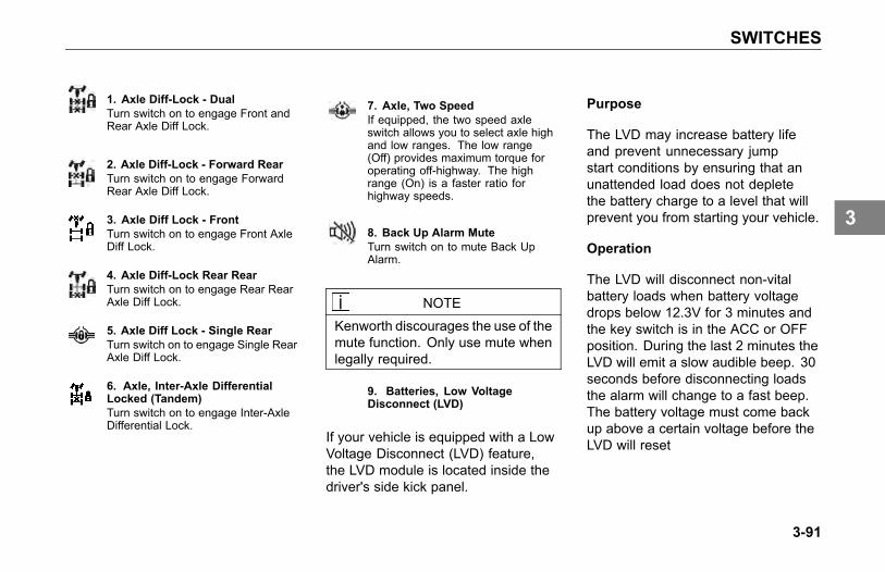
SWITCHES
1. Axle Diff-Lock - DualTurn switch on to engage Front andRear Axle Diff Lock.
2. Axle Diff-Lock - Forward RearTurn switch on to engage ForwardRear Axle Diff Lock.
3. Axle Diff Lock - FrontTurn switch on to engage Front AxleDiff Lock.
4. Axle Diff-Lock Rear RearTurn switch on to engage Rear RearAxle Diff Lock.
5. Axle Diff Lock - Single RearTurn switch on to engage Single RearAxle Diff Lock.
6. Axle, Inter-Axle DifferentialLocked (Tandem)Turn switch on to engage Inter-AxleDifferential Lock.
7. Axle, Two SpeedIf equipped, the two speed axleswitch allows you to select axle highand low ranges. The low range(Off) provides maximum torque foroperating off-highway. The highrange (On) is a faster ratio forhighway speeds.
8. Back Up Alarm MuteTurn switch on to mute Back UpAlarm.
NOTE
Kenworth discourages the use of themute function. Only use mute whenlegally required.
9. Batteries, Low VoltageDisconnect (LVD)
If your vehicle is equipped with a LowVoltage Disconnect (LVD) feature,the LVD module is located inside thedriver's side kick panel.
Purpose
The LVD may increase battery lifeand prevent unnecessary jumpstart conditions by ensuring that anunattended load does not depletethe battery charge to a level that willprevent you from starting your vehicle.
Operation
The LVD will disconnect non-vitalbattery loads when battery voltagedrops below 12.3V for 3 minutes andthe key switch is in the ACC or OFFposition. During the last 2 minutes theLVD will emit a slow audible beep. 30seconds before disconnecting loadsthe alarm will change to a fast beep.The battery voltage must come backup above a certain voltage before theLVD will reset
3-91
3

SWITCHES
See an authorized Kenworth Dealer ifthe LVD fails to reconnect loads duringnormal operation.
Circuits Disconnected By LVD
• Cab Dome Lamps
• Cab Accessories
• Spare Battery A & B
NOTEAll LVD circuits are color-coded blueon the central electrical panel coverlabel.
WARNING
Do not use the Spare BatteryA & B circuits or other circuitsthat are controlled by the LVD topower electronic engine controls,ABS circuits, or safety/work-relatedlighting. Before adding any deviceto the vehicle's electrical system,consult your nearest authorizedKenworth Dealer or read thecontents of TMC RP-136. Failureto do so may cause equipmentdamage or lead to personal injury.
NOTE
The determination of whatcircuits/loads that were connectedto the LVD was based upon therecommendation from Technologyand Maintenance Council (TMC) ofthe American Trucking Association.To review the recommendedpractice, see TMC RP-136.
10. Brakes, ABS Off-RoadTurn switch on to engage ABSOff-Road mode. See Anti-LockBraking System on page 3-31.
11. Brakes, Parking Brake ValvePull yellow knob to activate parkingbrakes. See Parking Brake Valve onpage 3-92.
12. Dump Truck GateTurn switch on to open Dump TruckGate.
13. Engine, Brake LevelIn the up position there will be 100%engine retarding. In the middleposition there will be 60% engineretarding. In the down position therewill be 33% engine retarding.
For more information on when andhow to use the engine brake in yourvehicle, see the engine brake owner’smanual for additional engine brakeinformation.
3-92
3
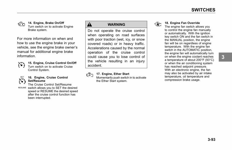
SWITCHES
14. Engine, Brake On/OffTurn switch on to activate EngineBrake system.
For more information on when andhow to use the engine brake in yourvehicle, see the engine brake owner’smanual for additional engine brakeinformation.
15. Engine, Cruise Control On/OffTurn switch on to activate CruiseControl System.
SET
RESUME
16. Engine, Cruise ControlSet/ResumeThe Cruise Control Set/Resumeswitch allows you to SET the desiredspeed or RESUME the desired speedafter the cruise control function hasbeen interrupted.
WARNING
Do not operate the cruise controlwhen operating on road surfaceswith poor traction (wet, icy, or snowcovered roads) or in heavy traffic.Accelerations caused by the normaloperation of the cruise controlcould cause you to lose control ofthe vehicle resulting in an injuryaccident.
17. Engine, Ether StartMomentarily push switch in to activatethe Ether Start system.
18. Engine Fan OverrideThe engine fan switch allows youto control the engine fan manuallyor automatically. With the ignitionkey switch ON and the fan switch inthe MANUAL position, the enginefan will be on regardless of enginetemperature. With the engine fanswitch in the AUTOMATIC position,the engine fan will automatically turnon when the engine coolant reachesa temperature of about 200°F (93°C)or when the air conditioning systemhas reached setpoint pressure.With an electronic engine, the fanmay also be activated by air intaketemperature, oil temperature andcompression brake usage.
3-93
3

SWITCHES
WARNING
Do not work on or near the fan withthe engine running. Anyone nearthe engine fan when it turns on couldbe seriously injured. If it is set atMANUAL, the fan will turn on anytime the ignition key switch is turnedto the ON position. In AUTO, it couldengage suddenly without warning.Before turning on the ignition orswitching from AUTO to MANUAL,be sure no workers are near the fan.
CAUTION
The fan or equipment near it couldbe damaged if the fan turns onsuddenly when you do not expect it.Keep all tools and equipment awayfrom the fan.
CAUTION
Do not operate the engine fan inthe MANUAL position for extendedperiods of time. The fan hub wasdesigned for intermittent operation.Sustained operation will shortenthe fan hub’s service life as well asreduce fuel economy.
19. Engine HeaterTurn switch on to activate the EngineHeater.
20. Engine, Remote ThrottleTurn switch on to activate RemoteThrottle Control.
21. Engine, ShutdownMomentarily push switch in to activatethe shutdown system.
22. Exhaust, Diesel ParticulateFilter (DPF) Regeneration SwitchManually controls the dieselparticulate filter regeneration process.Refer to Engine After-treatmentControls Operator's Manual foradditional information.
23. Fifth Wheel SlideTurn switch on to “Unlock” FifthWheel Slide mechanism.
NOTE
Vehicles having an air slide fifthwheel have a fifth wheel sliderlock controlled by a switch onthe instrument panel. By placingthe switch in the unlock positionyou can slide the fifth wheel tovarious positions to adjust weightdistribution.
The switch is guarded to protectyou from accidentally activating orreleasing the lock.
3-94
3
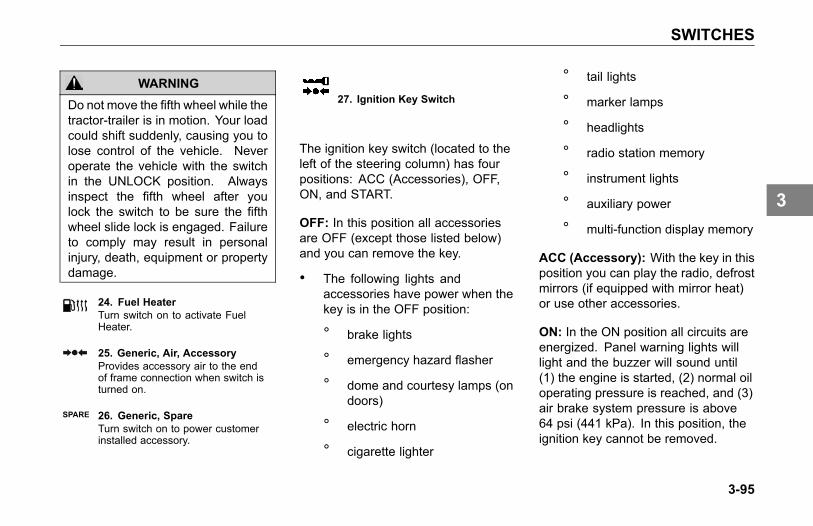
SWITCHES
WARNING
Do not move the fifth wheel while thetractor-trailer is in motion. Your loadcould shift suddenly, causing you tolose control of the vehicle. Neveroperate the vehicle with the switchin the UNLOCK position. Alwaysinspect the fifth wheel after youlock the switch to be sure the fifthwheel slide lock is engaged. Failureto comply may result in personalinjury, death, equipment or propertydamage.
24. Fuel HeaterTurn switch on to activate FuelHeater.
25. Generic, Air, AccessoryProvides accessory air to the endof frame connection when switch isturned on.
SPARE 26. Generic, SpareTurn switch on to power customerinstalled accessory.
27. Ignition Key Switch
The ignition key switch (located to theleft of the steering column) has fourpositions: ACC (Accessories), OFF,ON, and START.
OFF: In this position all accessoriesare OFF (except those listed below)and you can remove the key.
• The following lights andaccessories have power when thekey is in the OFF position:
° brake lights
° emergency hazard flasher
° dome and courtesy lamps (ondoors)
° electric horn
° cigarette lighter
° tail lights
° marker lamps
° headlights
° radio station memory
° instrument lights
° auxiliary power
° multi-function display memory
ACC (Accessory): With the key in thisposition you can play the radio, defrostmirrors (if equipped with mirror heat)or use other accessories.
ON: In the ON position all circuits areenergized. Panel warning lights willlight and the buzzer will sound until(1) the engine is started, (2) normal oiloperating pressure is reached, and (3)air brake system pressure is above64 psi (441 kPa). In this position, theignition key cannot be removed.
3-95
3
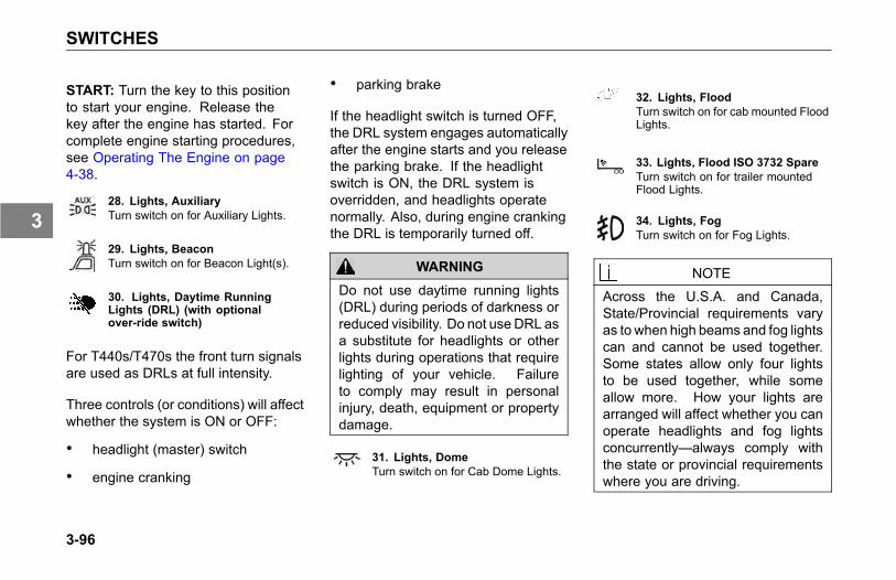
SWITCHES
START: Turn the key to this positionto start your engine. Release thekey after the engine has started. Forcomplete engine starting procedures,see Operating The Engine on page4-38.
28. Lights, AuxiliaryTurn switch on for Auxiliary Lights.
29. Lights, BeaconTurn switch on for Beacon Light(s).
30. Lights, Daytime RunningLights (DRL) (with optionalover-ride switch)
For T440s/T470s the front turn signalsare used as DRLs at full intensity.
Three controls (or conditions) will affectwhether the system is ON or OFF:
• headlight (master) switch
• engine cranking
• parking brake
If the headlight switch is turned OFF,the DRL system engages automaticallyafter the engine starts and you releasethe parking brake. If the headlightswitch is ON, the DRL system isoverridden, and headlights operatenormally. Also, during engine crankingthe DRL is temporarily turned off.
WARNING
Do not use daytime running lights(DRL) during periods of darkness orreduced visibility. Do not useDRL asa substitute for headlights or otherlights during operations that requirelighting of your vehicle. Failureto comply may result in personalinjury, death, equipment or propertydamage.
31. Lights, DomeTurn switch on for Cab Dome Lights.
32. Lights, FloodTurn switch on for cab mounted FloodLights.
33. Lights, Flood ISO 3732 SpareTurn switch on for trailer mountedFlood Lights.
34. Lights, FogTurn switch on for Fog Lights.
NOTE
Across the U.S.A. and Canada,State/Provincial requirements varyas to when high beams and fog lightscan and cannot be used together.Some states allow only four lightsto be used together, while someallow more. How your lights arearranged will affect whether you canoperate headlights and fog lightsconcurrently—always comply withthe state or provincial requirementswhere you are driving.
3-96
3
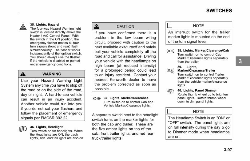
SWITCHES
35. Lights, HazardThe four-way Hazard Warning lightswitch is located directly above theHeater / A/C Control Panel. Withthe switch in the ON position, theemergency flasher makes all fourturn signals (front and rear) flashsimultaneously. The flasher worksindependently of the ignition switch.You should always use the flasherif the vehicle is disabled or parkedunder emergency conditions.
WARNING
Use your Hazard Warning LightSystem any time you have to stop offthe road or on the side of the road,day or night. A hard-to-see vehiclecan result in an injury accident.Another vehicle could run into youif you do not set your flashers andfollow the placement of emergencysignals per FMCSR 392.22.
36. Lights, HeadlightTurn switch on for headlights. Whenthe Headlights are ON, the dashlights, side, and tail lights are also on.
CAUTION
If you have confirmed there is aproblem in the low beam wiringcircuit, proceed with caution to thenext available exit/turnoff and safelypull your vehicle completely off theroad and call for assistance. Drivingyour vehicle with the headlamps onhigh beam (at reduced intensity)for a prolonged period could leadto an injury accident. Contact yournearest Kenworth dealer to havethe problem corrected as soon aspossible.
37. Lights, Marker/ClearanceTurn switch on to control Cab andVehicle Marker/Clearance lights.
A separate switch next to the headlightswitch turns on the marker lights forboth the cab and trailer. These arethe five amber lights on top of thecab, front trailer lights, and red reartruck/trailer lights.
NOTE
An interrupt switch for the trailermarker lights is mounted on the endof the turn signal lever.
38. Lights, Marker/Clearance/CabTurn switch on to control CabMarker/Clearance lights separatelyfrom the trailer.39. Lights,Marker/Clearance/TrailerTurn switch on to control TrailerMarker/Clearance lights separatelyfrom the vehicle marker/clearancelights.40. Lights, Panel DimmerRotate thumb wheel up to brightenpanel lights. Rotate thumb wheeldown to dim panel lights.
NOTE
The Headlamp Switch is an "ON" or"OFF" switch. The panel lights areon full intensity during the day & goto Dimmer mode when headlampsare on.
3-97
3
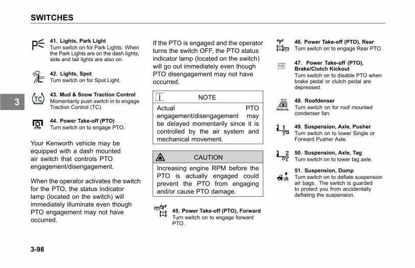
SWITCHES
41. Lights, Park LightTurn switch on for Park Lights. Whenthe Park Lights are on the dash lights,side and tail lights are also on.
42. Lights, SpotTurn switch on for Spot Light.
43. Mud & Snow Traction ControlMomentarily push switch in to engageTraction Control (TC).
44. Power Take-off (PTO)Turn switch on to engage PTO.
Your Kenworth vehicle may beequipped with a dash mountedair switch that controls PTOengagement/disengagement.
When the operator activates the switchfor the PTO, the status indicatorlamp (located on the switch) willimmediately illuminate even thoughPTO engagement may not haveoccurred.
If the PTO is engaged and the operatorturns the switch OFF, the PTO statusindicator lamp (located on the switch)will go out immediately even thoughPTO disengagement may not haveoccurred.
NOTE
Actual PTOengagement/disengagement maybe delayed momentarily since it iscontrolled by the air system andmechanical movement.
CAUTION
Increasing engine RPM before thePTO is actually engaged couldprevent the PTO from engagingand/or cause PTO damage.
45. Power Take-off (PTO), ForwardTurn switch on to engage forwardPTO.
46. Power Take-off (PTO), RearTurn switch on to engage Rear PTO.
47. Power Take-off (PTO),Brake/Clutch KickoutTurn switch on to disable PTO whenbrake pedal or clutch pedal aredepressed.
48. RoofdenserTurn switch on for roof mountedcondenser fan.
49. Suspension, Axle, PusherTurn switch on to lower Single orForward Pusher Axle.
50. Suspension, Axle, TagTurn switch on to lower tag axle.
51. Suspension, DumpTurn switch on to deflate suspensionair bags. The switch is guardedto protect you from accidentallydeflating the suspension.
3-98
3
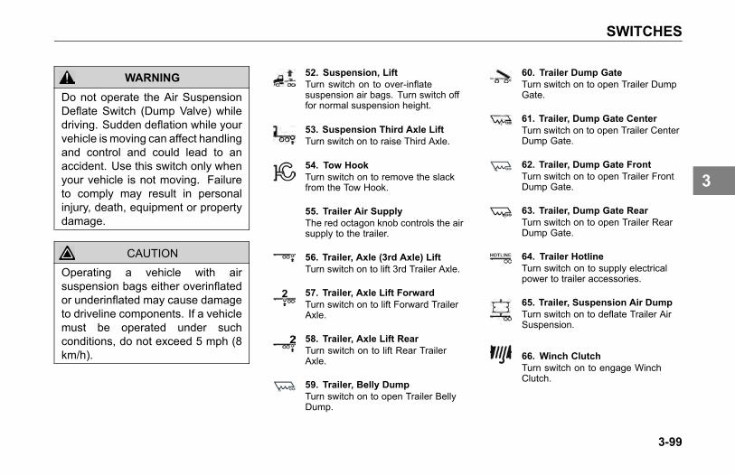
SWITCHES
WARNING
Do not operate the Air SuspensionDeflate Switch (Dump Valve) whiledriving. Sudden deflation while yourvehicle is moving can affect handlingand control and could lead to anaccident. Use this switch only whenyour vehicle is not moving. Failureto comply may result in personalinjury, death, equipment or propertydamage.
CAUTION
Operating a vehicle with airsuspension bags either overinflatedor underinflated may cause damageto driveline components. If a vehiclemust be operated under suchconditions, do not exceed 5 mph (8km/h).
52. Suspension, LiftTurn switch on to over-inflatesuspension air bags. Turn switch offfor normal suspension height.
53. Suspension Third Axle LiftTurn switch on to raise Third Axle.
54. Tow HookTurn switch on to remove the slackfrom the Tow Hook.
55. Trailer Air SupplyThe red octagon knob controls the airsupply to the trailer.
56. Trailer, Axle (3rd Axle) LiftTurn switch on to lift 3rd Trailer Axle.
57. Trailer, Axle Lift ForwardTurn switch on to lift Forward TrailerAxle.
58. Trailer, Axle Lift RearTurn switch on to lift Rear TrailerAxle.
59. Trailer, Belly DumpTurn switch on to open Trailer BellyDump.
60. Trailer Dump GateTurn switch on to open Trailer DumpGate.
61. Trailer, Dump Gate CenterTurn switch on to open Trailer CenterDump Gate.
62. Trailer, Dump Gate FrontTurn switch on to open Trailer FrontDump Gate.
63. Trailer, Dump Gate RearTurn switch on to open Trailer RearDump Gate.
64. Trailer HotlineTurn switch on to supply electricalpower to trailer accessories.
65. Trailer, Suspension Air DumpTurn switch on to deflate Trailer AirSuspension.
66. Winch ClutchTurn switch on to engage WinchClutch.
3-99
3
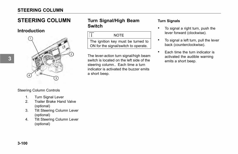
STEERING COLUMN
STEERING COLUMN
Introduction
Steering Column Controls
1. Turn Signal Lever2. Trailer Brake Hand Valve
(optional)3. Tilt Steering Column Lever
(optional)4. Tilt Steering Column Lever
(optional)
Turn Signal/High BeamSwitch
NOTEThe ignition key must be turned toON for the signal/switch to operate.
The lever-action turn signal/high beamswitch is located on the left side of thesteering column.. Each time a turnindicator is activated the buzzer emitsa short beep.
Turn Signals
• To signal a right turn, push thelever forward (clockwise).
• To signal a left turn, pull the leverback (counterclockwise).
• Each time the turn indicator isactivated the audible warningemits a short beep.
3-100
3
STEERING COLUMN
NOTE
If the vehicle turn signals and turnsignal indicators in the dash gaugecluster ever begin flashing at anaccelerated rate (115 cycles perminute) when the turn signal lever isin the OFF (center) position, or whena Right/Left turn has been selected,the problem may be related to afailed turn signal switch or turn signalmodule. In either case, the problemis not a failed bulb. Contact yournearest authorized Kenworth Dealerto have the problem corrected assoon as possible.
CAUTION
After you complete a turn, shutthe system off by returning thelever to the “OFF” (center) position.The switch's lever action is NOTself-canceling. Failure to shutoff a turn signal could confuseother drivers and result in an injuryaccident. An indicator light in theinstrument panel will flash until theturn signal is turned off.
High Beam
NOTE
The headlights must be ON for thehigh beam switch to operate.
• To switch your headlights to loweror higher beam, gently pull the turnsignal lever, toward the steeringwheel, until you hear the switchclick and the beam changes.The blue indicator light in theinstrument panel will be ON whenthe high beam is being used.
• To return to previous beam: pullthe lever towards the steeringwheel again.
• To momentarily flash yourheadlights (illuminating thehigh-beams), push the turn signallever forward.
3-101
3
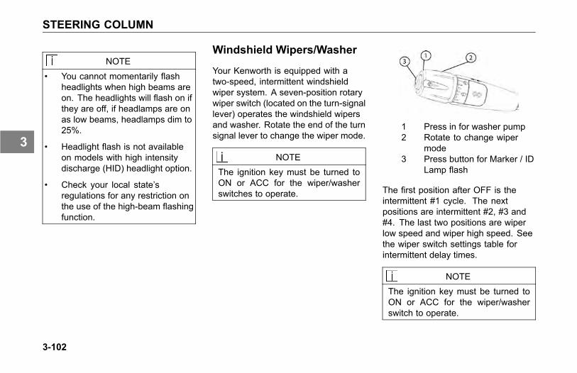
STEERING COLUMN
NOTE
• You cannot momentarily flashheadlights when high beams areon. The headlights will flash on ifthey are off, if headlamps are onas low beams, headlamps dim to25%.
• Headlight flash is not availableon models with high intensitydischarge (HID) headlight option.
• Check your local state’sregulations for any restriction onthe use of the high-beam flashingfunction.
Windshield Wipers/Washer
Your Kenworth is equipped with atwo-speed, intermittent windshieldwiper system. A seven-position rotarywiper switch (located on the turn-signallever) operates the windshield wipersand washer. Rotate the end of the turnsignal lever to change the wiper mode.
NOTEThe ignition key must be turned toON or ACC for the wiper/washerswitches to operate.
1 Press in for washer pump2 Rotate to change wiper
mode3 Press button for Marker / ID
Lamp flash
The first position after OFF is theintermittent #1 cycle. The nextpositions are intermittent #2, #3 and#4. The last two positions are wiperlow speed and wiper high speed. Seethe wiper switch settings table forintermittent delay times.
NOTEThe ignition key must be turned toON or ACC for the wiper/washerswitch to operate.
3-102
3
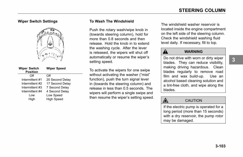
STEERING COLUMN
Wiper Switch Settings
Wiper SwitchPosition
Wiper Speed
Off OffIntermittent #1 20 Second DelayIntermittent #2 17 Second DelayIntermittent #3 7 Second DelayIntermittent #4 4 Second Delay
Low Low SpeedHigh High Speed
To Wash The Windshield
Push the rotary wash/wipe knob in(towards steering column), hold formore than 0.8 seconds and thenrelease. Hold the knob in to extendthe washing cycle. After the leveris released, the wipers will shut offautomatically or resume the wiper’ssetting speed.
To activate the wipers for one swipewithout activating the washer (“mist”function), push the turn signal leverin (towards the steering column) andrelease in less than 0.5 seconds. Thewipers will perform a single swipe andthen resume the wiper’s setting speed.
The windshield washer reservoir islocated inside the engine compartmenton the left side of the steering column.Check the windshield washing fluidlevel daily. If necessary, fill to top.
WARNING
Do not drive with worn or dirty wiperblades. They can reduce visibility,making driving hazardous. Cleanblades regularly to remove roadfilm and wax build-up. Use analcohol based cleaning solution anda lint-free cloth, and wipe along theblades.
CAUTION
If the electric pump is operated for along period (more than 15 seconds)with a dry reservoir, the pump rotormay be damaged.
3-103
3

STEERING COLUMN
Clean all inside and outside windowsregularly. Use an alcohol-basedcleaning solution and wipe dry witheither a lintfree or a chamois cloth.Avoid running the wiper blades over adry windshield to prevent scratchingthe glass. Spray on washer fluid first.A scratched windshield will reducevisibility.
Trailer Brake Hand Valve
This hand valve, mounted on thesteering wheel column, provides airpressure to apply the trailer brakesonly. It operates independently ofthe foot treadle valve. See Using theBrake System on page 4-17, for moreinstructions on proper use of the TrailerBrake Hand Valve.
Stop/Turn Signal LampOperation
Your Kenworth vehicle uses combinedstop/turn signal lamps at the rear ofthe vehicle, using the same bulb toperform both functions. This means asingle bulb is used for the brake lampas well as the turn signal lamp. Thisbulb will burn steadily with the brakesapplied. The same bulb will flash withthe turn signal activated, even with thebrakes applied.
3-104
3
STEERING COLUMN
Maximum Number Of LampsAllowed Per Circuit
• Vehicle Stop/Turn Signal Circuit
The lighting control unit is limitedto 5 amps total, or two (2) 25 wattincandescent bulbs per side. Do notwire more than two incandescent bulbsper side to the vehicle tail lamp fixtures.If more than two bulbs are requiredfor each tail lamp fixture, install LEDtype lamps, or contact your nearestKenworth dealer for other options.
• Trailer Turn and Vehicle ForwardSide Facing Turn Lamp Circuit
The lighting control unit is limitedto 20 amps or nine (9) 25 wattincandescent bulbs total (per side) forthe combination of trailer turn lampsand vehicle forward side facing turnlamps. Do not wire more than nineincandescent bulbs per side for thecombination of trailer turn lamps andvehicle forward side facing turn lamps.
If more than nine bulbs per side arerequired, install LED type lamps, orcontact your nearest Kenworth dealerfor other options.
CAUTION
Before installing additional vehiclestop/turn lamps, trailer turn lamps oradditional forward side facing turnlamps on the vehicle, make sure thelighting circuit limits described aboveare not exceeded. Exceeding thenumber of lamps designated abovecan/will cause the electronic controlunit to default to a protection mode,causing the lamps to not functionproperly.
Similar to the headlamp system, if aproblem is detected with the electroniccontrol unit, the control unit will cyclethe turn signals off once every 9seconds. You can detect that this isoccurring if the turn signal indicators inthe dash operate intermittently.
If you experience intermittent turnsignal operation, the problem is eithera short in the turn signal circuit or themaximum number of bulbs has beenexceeded for the circuit.
If you experience any vehicle stop/turnsignal issues, contact your nearestKenworth dealer.
3-105
3
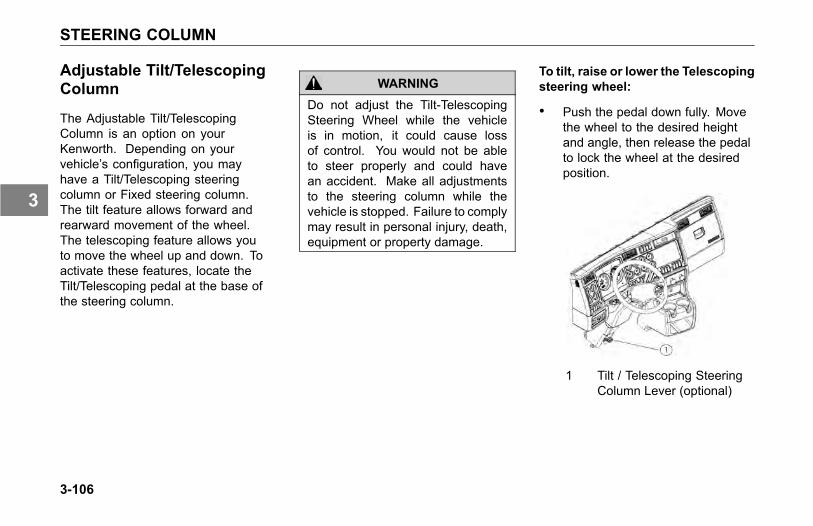
STEERING COLUMN
Adjustable Tilt/TelescopingColumn
The Adjustable Tilt/TelescopingColumn is an option on yourKenworth. Depending on yourvehicle’s configuration, you mayhave a Tilt/Telescoping steeringcolumn or Fixed steering column.The tilt feature allows forward andrearward movement of the wheel.The telescoping feature allows youto move the wheel up and down. Toactivate these features, locate theTilt/Telescoping pedal at the base ofthe steering column.
WARNING
Do not adjust the Tilt-TelescopingSteering Wheel while the vehicleis in motion, it could cause lossof control. You would not be ableto steer properly and could havean accident. Make all adjustmentsto the steering column while thevehicle is stopped. Failure to complymay result in personal injury, death,equipment or property damage.
To tilt, raise or lower the Telescopingsteering wheel:
• Push the pedal down fully. Movethe wheel to the desired heightand angle, then release the pedalto lock the wheel at the desiredposition.
1 Tilt / Telescoping SteeringColumn Lever (optional)
3-106
3

STEERING COLUMN
Horn
Your vehicle may be equipped withair horns. To operate, pull on thelanyard extending from the overheadheader panel. Your vehicle may alsohave an electric horn. To sound theelectric horn, press the button in thecenter of the steering wheel, whichis the standard location for electrichorns (optional horn locations may berequested).
SmartWheel MultiplexControl System
CAUTIONUnder no circumstances shouldyou attempt to service the steeringwheel, clockspring, or any of theelectrical wiring in the multiplexsystem, or any steering components(steering column, steering drivelineor steering gear). Tampering withthese components may result in aninoperable multiplex system.
System Description
The multiplex steering wheel systemconsists of the steering wheel mountedcontrols, the multiplex electronicsmodule, the clockspring in the steeringcolumn and the interconnecting wireharnesses.
The steering wheel mounted controlstell the multiplex electronics module(located behind the dash) whichelectrical circuit to turn on or off.The controls are connected to theelectronics module with two wires,using a "multiplexed" electronic signal.This multiplexed signal allows morethan one switch to use the same pairof wires.
3-107
3
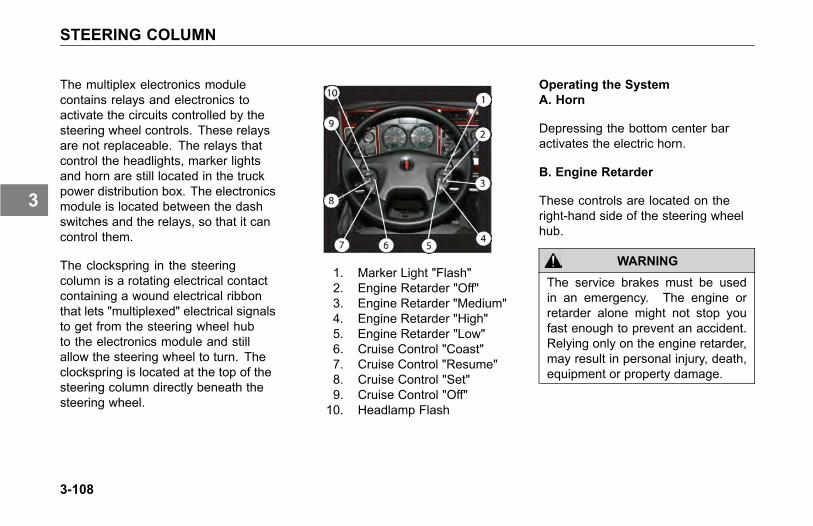
STEERING COLUMN
The multiplex electronics modulecontains relays and electronics toactivate the circuits controlled by thesteering wheel controls. These relaysare not replaceable. The relays thatcontrol the headlights, marker lightsand horn are still located in the truckpower distribution box. The electronicsmodule is located between the dashswitches and the relays, so that it cancontrol them.
The clockspring in the steeringcolumn is a rotating electrical contactcontaining a wound electrical ribbonthat lets "multiplexed" electrical signalsto get from the steering wheel hubto the electronics module and stillallow the steering wheel to turn. Theclockspring is located at the top of thesteering column directly beneath thesteering wheel.
11. Marker Light "Flash"12. Engine Retarder "Off"13. Engine Retarder "Medium"14. Engine Retarder "High"15. Engine Retarder "Low"16. Cruise Control "Coast"17. Cruise Control "Resume"18. Cruise Control "Set"19. Cruise Control "Off"10. Headlamp Flash
Operating the SystemA. Horn
Depressing the bottom center baractivates the electric horn.
B. Engine Retarder
These controls are located on theright-hand side of the steering wheelhub.
WARNING
The service brakes must be usedin an emergency. The engine orretarder alone might not stop youfast enough to prevent an accident.Relying only on the engine retarder,may result in personal injury, death,equipment or property damage.
3-108
3

STEERING COLUMN
WARNING
The engine retarder is NOT intendedas the primary brake for the vehicle,nor is it an emergency brake. Theengine retarder only helps theservice brakes by using enginepressure to slow the drivetrain. Usethe service brakes for quick stops.Failure to comply may result inpersonal injury, death, equipment orproperty damage.
WARNING
Do not operate the engine retarderwhen driving/operating your vehiclebobtail or with a loaded or unloadedtrailer on road surfaces with poortraction (wet, icy, or snow coveredroads) or in heavy traffic. Brakingcaused by the normal operation ofthe engine retarder could cause youto lose control of the vehicle andmay result in personal injury, death,equipment or property damage.
NOTEThe exhaust brake and enginebrake are two types of engineretarders. Refer also to the enginemanufacturer’s Operator Manualand to the Engine Retarder manualfor additional instructions.
• To Activate:To activate the desired engineretarder setting:
Press for LOW.
Press for MEDIUM.
Press for HIGH.
NOTEYour engine may only have 2engine retarder settings, LOW andHIGH. If so, the MEDIUM button isnon-operational.
• To Turn Off:
Press for OFF.
C. Cruise Control
These controls are located on theleft-hand side of the steering wheelhub.
WARNING
Do not operate the cruise controlwhen operating on road surfaceswith poor traction (wet, icy, or snowcovered roads) or in heavy traffic.Accelerations caused by the normaloperation of the cruise controlcould cause you to lose control ofthe vehicle resulting in an injuryaccident.
3-109
3
STEERING COLUMN
• To Turn On:
Press the ON button.
• To Turn Off:
Press the OFF button. Any previousspeed settings are cleared.
Using Cruise Control While Driving
Setting Cruise Speed
1. Ensure that the vehicle speed isabove the minimum cruise controlspeed (15 mph for Caterpillarengines, 30 mph for the Cumminsengines) and the engine speed isabove 1100 rpm.
2. Press the "ON" button.
3. Accelerate the vehicle to thedesired cruise speed.
4. Press the "SET" button to set thecruise speed.
NOTE
Cruise Control may not hold the setspeed going down hills. If the speedincreases going down a hill, usethe brakes to slow down. This willcancel Cruise Control.
Changing the Cruise Set Speed
• To increase the cruise set speed:
Press the "SET" button until thedesired speed is achieved, thenrelease the button.
• To decrease the cruise set speed:
Press the "RESUME" button andcoast to the desired lower speed, thenrelease the button.
Cancelling Cruise Control
You can cancel cruise control in anyof these ways:
• Tap the brake pedal.
• Tap the clutch pedal.
• Press the "OFF" button.
3-110
3
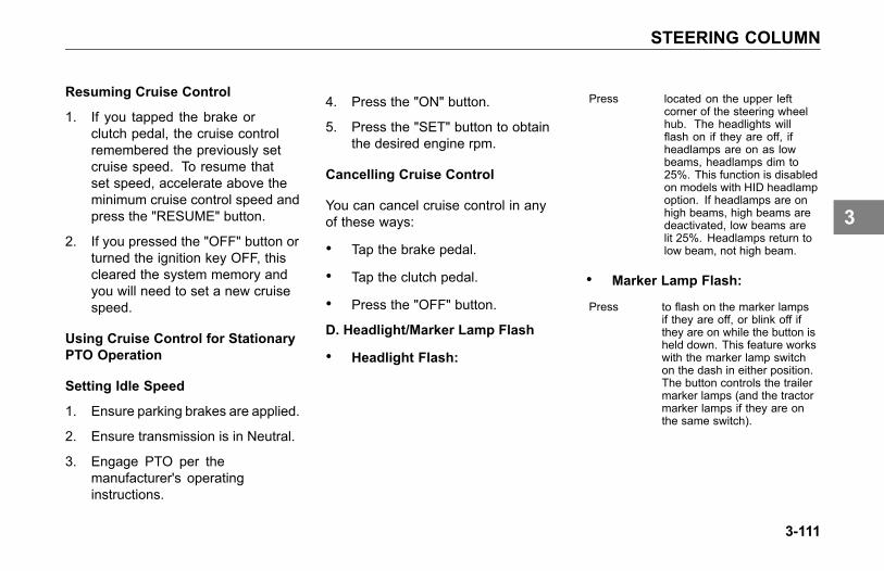
STEERING COLUMN
Resuming Cruise Control
1. If you tapped the brake orclutch pedal, the cruise controlremembered the previously setcruise speed. To resume thatset speed, accelerate above theminimum cruise control speed andpress the "RESUME" button.
2. If you pressed the "OFF" button orturned the ignition key OFF, thiscleared the system memory andyou will need to set a new cruisespeed.
Using Cruise Control for StationaryPTO Operation
Setting Idle Speed
1. Ensure parking brakes are applied.
2. Ensure transmission is in Neutral.
3. Engage PTO per themanufacturer's operatinginstructions.
4. Press the "ON" button.
5. Press the "SET" button to obtainthe desired engine rpm.
Cancelling Cruise Control
You can cancel cruise control in anyof these ways:
• Tap the brake pedal.
• Tap the clutch pedal.
• Press the "OFF" button.
D. Headlight/Marker Lamp Flash
• Headlight Flash:
Press located on the upper leftcorner of the steering wheelhub. The headlights willflash on if they are off, ifheadlamps are on as lowbeams, headlamps dim to25%. This function is disabledon models with HID headlampoption. If headlamps are onhigh beams, high beams aredeactivated, low beams arelit 25%. Headlamps return tolow beam, not high beam.
• Marker Lamp Flash:
Press to flash on the marker lampsif they are off, or blink off ifthey are on while the button isheld down. This feature workswith the marker lamp switchon the dash in either position.The button controls the trailermarker lamps (and the tractormarker lamps if they are onthe same switch).
3-111
3

MIRRORS
MIRRORS
Introduction
Your vehicle comes equipped with twooutside rear view mirrors that enableyou to see to the sides and behindyour vehicle. Be sure both mirrors areadjusted properly before you begindriving.
WARNING
Adjust all mirrors before driving.Adjusting the mirrors while drivingcan cause you to take your eyesoff the road, which could result inan accident. Failure to do so couldlead to serious injury or equipmentdamage.
To provide good visibility, adjust themirror so the side of your vehicleappears in the inboard part of themirror.
WARNING
Convex mirrors can distort imagesand make objects appear smallerand farther away than they reallyare. You could have an accident ifyou are too close to another vehicleor other object. Keep plenty ofspace between your vehicle andothers when you turn or changelanes. Remember that other objectsare closer than they may appear.
Power Mirror Switch
If your vehicle is equipped with powermirrors, the directional controls forboth mirrors are located near the top ofthe driver side door trim pad.
1. Power Mirror & HeatedMirror Controls
3-112
3
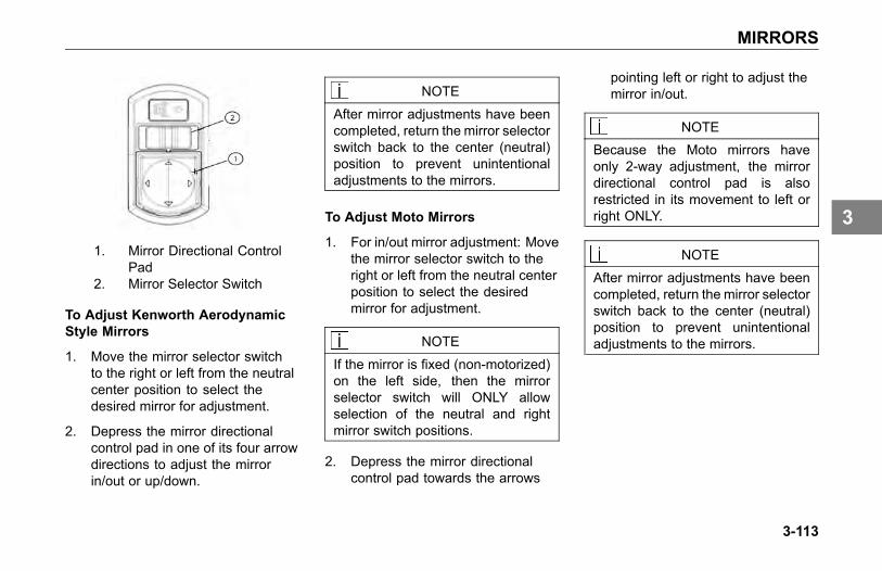
MIRRORS
1. Mirror Directional ControlPad
2. Mirror Selector Switch
To Adjust Kenworth AerodynamicStyle Mirrors
1. Move the mirror selector switchto the right or left from the neutralcenter position to select thedesired mirror for adjustment.
2. Depress the mirror directionalcontrol pad in one of its four arrowdirections to adjust the mirrorin/out or up/down.
NOTE
After mirror adjustments have beencompleted, return the mirror selectorswitch back to the center (neutral)position to prevent unintentionaladjustments to the mirrors.
To Adjust Moto Mirrors
1. For in/out mirror adjustment: Movethe mirror selector switch to theright or left from the neutral centerposition to select the desiredmirror for adjustment.
NOTE
If the mirror is fixed (non-motorized)on the left side, then the mirrorselector switch will ONLY allowselection of the neutral and rightmirror switch positions.
2. Depress the mirror directionalcontrol pad towards the arrows
pointing left or right to adjust themirror in/out.
NOTEBecause the Moto mirrors haveonly 2-way adjustment, the mirrordirectional control pad is alsorestricted in its movement to left orright ONLY.
NOTE
After mirror adjustments have beencompleted, return the mirror selectorswitch back to the center (neutral)position to prevent unintentionaladjustments to the mirrors.
3-113
3
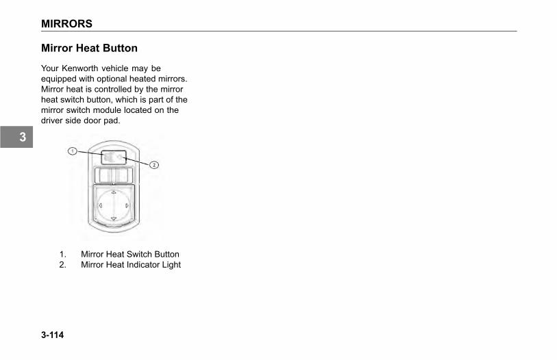
MIRRORS
Mirror Heat Button
Your Kenworth vehicle may beequipped with optional heated mirrors.Mirror heat is controlled by the mirrorheat switch button, which is part of themirror switch module located on thedriver side door pad.
1. Mirror Heat Switch Button2. Mirror Heat Indicator Light
3-114
3

DRIVING
DRIVING TIPS AND TECHNIQUESIntroduction . . . . . . . . . . . . . . . . . . 4-5Coasting . . . . . . . . . . . . . . . . . . . . 4-5Descending a Grade . . . . . . . . . . . . . . 4-6Economical Driving . . . . . . . . . . . . . . . 4-6Fuel - Excess Consumption . . . . . . . . . . . 4-8Safe Driving . . . . . . . . . . . . . . . . . 4-10Cruise Control . . . . . . . . . . . . . . . . 4-12Air Suspension Height/Air Pressure . . . . . . . 4-12Fifth Wheel. . . . . . . . . . . . . . . . . . 4-14
OPERATING THE BRAKE SYSTEMIntroduction . . . . . . . . . . . . . . . . . 4-17Air Supply System . . . . . . . . . . . . . . 4-18Using the Parking Brake . . . . . . . . . . . . 4-20Vehicle/Trailer Air Supply Valve . . . . . . . . . 4-23Brake Safety and Emergency. . . . . . . . . . 4-26Anti-Lock Braking System . . . . . . . . . . . 4-27
4-1
4
DRIVING
Trailer Brake Hand Valve. . . . . . . . . . . . 4-32Driving With an Unloaded Trailer . . . . . . . . 4-33Engine Retarders . . . . . . . . . . . . . . . 4-33Exhaust Brake . . . . . . . . . . . . . . . . 4-34Engine Brakes . . . . . . . . . . . . . . . . 4-35Brake Components . . . . . . . . . . . . . . 4-36
OPERATING THE ENGINEIntroduction . . . . . . . . . . . . . . . . . 4-38Starting Procedure - Normal Temperature . . . . 4-39Starting Procedure - Cold Weather . . . . . . . 4-41Engine Warm-Up and Idling . . . . . . . . . . 4-42Idling the Engine . . . . . . . . . . . . . . . 4-45Cruise Control . . . . . . . . . . . . . . . . 4-46Engine Fan Control . . . . . . . . . . . . . . 4-48Engine Control Display . . . . . . . . . . . . 4-49Engine Shutdown System . . . . . . . . . . . 4-49
OPERATING THE REAR/DRIVE AXLEIntroduction . . . . . . . . . . . . . . . . . 4-50
4-2
4
DRIVING
Inter-Axle Differential Lock . . . . . . . . . . . 4-50Driver Controlled Main Differential Lock . . . . . 4-53Dual Range (Two-Speed) Rear Axle . . . . . . . 4-54Auxiliary Axles - Pusher or Tag . . . . . . . . . 4-56
OPERATING THE TRANSMISSIONIntroduction . . . . . . . . . . . . . . . . . 4-64Transmission Warm-Up . . . . . . . . . . . . 4-64Operating Manual Transmissions . . . . . . . . 4-65Putting the Vehicle in Motion . . . . . . . . . . 4-65More Transmission Tips . . . . . . . . . . . . 4-68Operating Automatic Transmissions . . . . . . . 4-70Auxiliary Transmissions . . . . . . . . . . . . 4-71Steerable Drive Axle . . . . . . . . . . . . . 4-71
SHUT-DOWNIntroduction . . . . . . . . . . . . . . . . . 4-72Final Stopping Procedures . . . . . . . . . . . 4-72Before Stopping the Engine . . . . . . . . . . 4-73Refueling . . . . . . . . . . . . . . . . . . 4-74
4-3
4

DRIVING TIPS AND TECHNIQUES
DRIVING TIPS ANDTECHNIQUES
Introduction
This section covers driving tips andtechniques on how to drive yourKenworth efficiently. For furtherinformation on driving techniques, readthe Truck Driver Handbook includedin your glove box literature package.It will give you more tips on starting,shifting, and driving your vehicle.
Coasting
Do not coast with the transmissionin neutral or with the clutch pedaldepressed.
WARNING
Do not coast with the transmissionin neutral or with the clutch pedaldepressed, it is a dangerouspractice. Without the use of theretarding power of the drivetrain,your vehicle can reach dangerousspeeds. At very high speedsyou may not be able to put thetransmission in any gear. At highspeeds you could seriously damageyour vehicle or cause an accidentwhen you put the transmission ingear. The engine speed couldexceed the maximum governedspeed and cause a serious accidentdue to mechanical failures. Failureto comply may result in personalinjury, death, equipment or propertydamage.
4-5
4
DRIVING TIPS AND TECHNIQUES
Besides being illegal and dangerous,coasting is also expensive. It causespremature failure or damage to theclutch and transmission and overloadsthe brake system.
Coasting with the transmissionin neutral also prevents propertransmission component lubrication.During coasting the transmission isdriven by the rear wheels, and thecountershaft gear (which lubricatesthe transmission components by oilsplash) will only be turning at idlespeed.
Descending a Grade
WARNING
Do not hold the brake pedal downtoo long or too often while goingdown a steep or long grade. Thiscould cause the brakes to overheatand reduce their effectiveness. Asa result, the vehicle will not slowdown at the usual rate. To reducethe risk of personal injury and/or anaccident, before going down a steepor long grade, reduce speed andshift the transmission into a lowergear to help control your vehiclespeed. Failure to follow proceduresfor proper downhill operation couldresult in loss of vehicle control andmay result in personal injury, death,equipment or property damage.
Economical Driving
The following section includesrecommendations for best engineperformance and economy:
4-6
4
DRIVING TIPS AND TECHNIQUES
Engine Overspeed - RPM
• Operate the engine within theoptimum engine RPM range anddo not allow the RPM's to exceedthe maximum governed speed.See your Engine Operationand Maintenance manual forinformation regarding engineRPM.
• When the engine is used as abrake to control vehicle speed(e.g., while driving down a grade),do not allow the engine RPMto exceed maximum governedspeed.
• Under normal load and roadconditions operate the engine inthe lower end of the range.
NOTE
Often these recommendationsare secondary to maintaining anadequate and safe speed relativeto the surrounding traffic and roadconditions.
CAUTIONTo avoid engine damage, do notlet the engine RPM go beyond themaximum governed RPM valvedamage could result if overspeedconditions occur.
Use of Tachometer
The tachometer is an instrument thataids in obtaining the best performanceof the engine and manual transmission,serving as a guide for shifting gears.Refer to the Engine Operation andMaintenance manual for optimumengine RPM.
• If the engine RPM moves beyondthe maximum governed speed,indicating an overspeed condition,apply the service brake or shift toa higher gear to bring engine RPMwithin the optimum speed range.
• When driving downhill: shift to alower gear, use the engine brake(if so equipped), and use theservice brake, keeping the enginespeed below 2,100 rpm.
4-7
4
DRIVING TIPS AND TECHNIQUES
When the engine speed reachesits maximum governed speed, theinjection pump governor cuts off fuelto the engine. However, the governorhas no control over the engine RPMwhen it is being driven by the vehicle'stransmission, for example, on steepdowngrades. Apply service brakes orshift to a higher gear.
Fuel economy and engineperformance are also directlyrelated to driving habits:
• The best results in trip time andfuel economy are obtained whiledriving the vehicle at a steadyspeed.
• Shift into higher or lower gears (orapply the service brake) to keepengine RPM near the lower end ofthe optimum operating range.
• Avoid rapid acceleration andbraking.
Fuel - Excess Consumption
The vehicle's fuel consumption isconnected to three important factors:maintenance, driving habits, andgeneral condition of the road, trafficconditions, and vehicle load.
4-8
4
DRIVING TIPS AND TECHNIQUES
Maintenance
Proper maintenance will keep thevehicle running like new even afterlong periods of use. The driver mustperform the daily and weekly checksof the vehicle.
Maintenance factors affecting fuelconsumption:
• air and/or fuel filters partiallyclogged
• engine valves out of adjustment
• injection pump improperlysynchronized
• injection nozzles defective oruncalibrated
• improperly inflated tires
• wheel bearings improperlyadjusted
• clutch improperly adjusted or worn(slipping)
• fuel leaks
Driving Habits
Wrong driving habits must becorrected and the recommendationson economic driving should befollowed.
Driving factors affecting fuelconsumption:
• excessive speed and unnecessaryfast acceleration
• long periods of idling
• driving with foot resting on the(manual transmission) clutchpedal
4-9
4

DRIVING TIPS AND TECHNIQUES
General Condition
Other factors affecting fuelconsumption are related to loadsand type of roads on which the vehicleoperates. It is not always possible tochoose the most adequate road, butit must be kept in mind that the idealroad is the one that allows a steadyspeed in high gear, without requiringfrequent braking and acceleration.
The following general conditionscan affect fuel consumption:
• overload
• unbalanced load
• very high load
• inadequate roads
• traffic conditions
Safe Driving
NOTE
The following recommendations aremerely informative and do not coverall safety precautions. Safe drivingis, above all, the responsibility of thedriver.
The safe operation of a vehicle isnot just following the establishedtraffic rules, but should also include:maintaining the vehicle in goodmechanical condition, and properoperation of the engine, transmission,and brakes.
The following guidelines will helpyou to drive the vehicle safely:
• Make a thorough inspection of thevehicle, daily and weekly. SeeDriver's Check List on page 1-28.
• Ensure that windows, mirrors, andlights are clean.
• Check all tires for damage andcorrect inflation pressure.
• Adjust the seat to a comfortabledriving position, for easy access topedals and vehicle controls.
• Adjust rear view mirrors.
• Always use the safety belts.
• Do not exceed the GVWR.
• Proportionally distribute loads onthe frame.
4-10
4

DRIVING TIPS AND TECHNIQUES
• Always keep the brakes adjustedand in proper condition. SeeChecks and Adjustments on page5-45.
• Obey speed limits and all trafficsignals.
• When driving downhill, select onegear lower than the up-hill gear.And use the brakes properly, donot ride them.
• Do not exceed maximum governedspeed (as specified in the EngineOperation and MaintenanceManual).
WARNING
Do not exceed the specified loadrating. Overloading can result inloss of vehicle control and personalinjury, either by causing componentfailures or by affecting vehiclehandling. Exceeding load ratingscan also shorten the service lifeof the vehicle. Failure to complymay result in personal injury, death,equipment or property damage.
• The components of yourvehicle are designed to providesatisfactory service if the vehicleis not loaded in excess of eitherthe gross vehicle weight rating(GVWR), or the maximum frontand rear gross axle weight ratings(GAWRs). (Axle weight ratings arelisted on the driver's door edge.)
NOTE
For your safety and the safety ofothers, follow routine and periodicmaintenance schedules for allcomponents on your vehicle. SeeTable 9, Maintenance Schedule onpage 5-17.
4-11
4
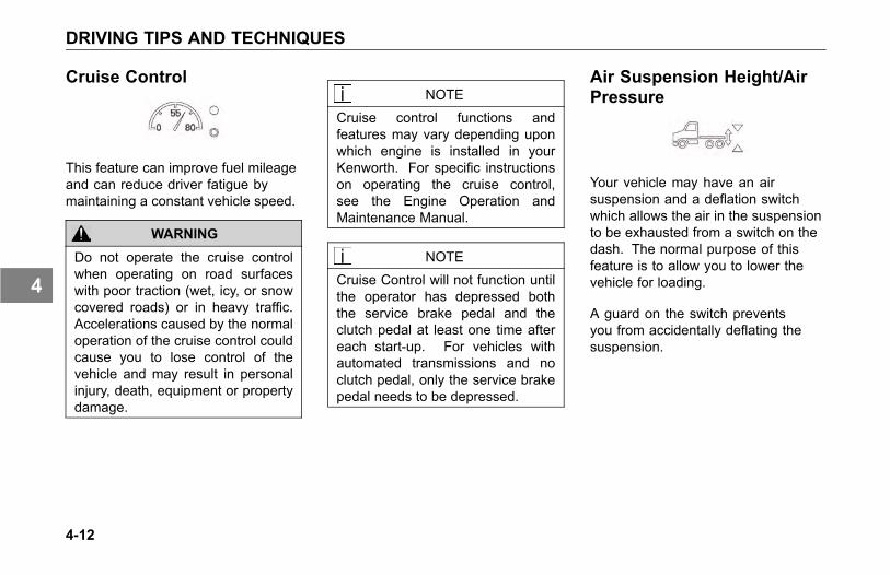
DRIVING TIPS AND TECHNIQUES
Cruise Control
This feature can improve fuel mileageand can reduce driver fatigue bymaintaining a constant vehicle speed.
WARNING
Do not operate the cruise controlwhen operating on road surfaceswith poor traction (wet, icy, or snowcovered roads) or in heavy traffic.Accelerations caused by the normaloperation of the cruise control couldcause you to lose control of thevehicle and may result in personalinjury, death, equipment or propertydamage.
NOTE
Cruise control functions andfeatures may vary depending uponwhich engine is installed in yourKenworth. For specific instructionson operating the cruise control,see the Engine Operation andMaintenance Manual.
NOTE
Cruise Control will not function untilthe operator has depressed boththe service brake pedal and theclutch pedal at least one time aftereach start-up. For vehicles withautomated transmissions and noclutch pedal, only the service brakepedal needs to be depressed.
Air Suspension Height/AirPressure
Your vehicle may have an airsuspension and a deflation switchwhich allows the air in the suspensionto be exhausted from a switch on thedash. The normal purpose of thisfeature is to allow you to lower thevehicle for loading.
A guard on the switch preventsyou from accidentally deflating thesuspension.
4-12
4
DRIVING TIPS AND TECHNIQUES
CAUTION
Operating a vehicle with airsuspension bags either overinflatedor under-inflated may causedamage to driveline components. Ifa vehicle must be operated undersuch conditions, do not exceed 5mph (8 km/h). Failure to complymay result in equipment damage.
Suspension Air Pressure Gauge
The Suspension Air Pressure gauge(option), see Optional Gauges on page3-62, which indicates the amount of airpressure in the air suspension springsin pounds per square inch (psi). Airpressure in the spring is related tothe rear axle load. The greater therear axle load, the greater the airpressure in the air bags. Therefore,the air pressure displayed will vary,depending upon the rear axle load.
Driving with Deflated Air Springs
If an air spring ruptures, there willbe enough air pressure to drive thevehicle to a safe stop off the highwayto investigate the problem.
4-13
4

DRIVING TIPS AND TECHNIQUES
To get to a repair facility, do thefollowing:
1. Remove the height control linkconnected to the axle and tothe suspension air valve controlarm. This will cause the air valvecontrol arm to center in the closedposition.
2. The air system can then bepumped up to normal pressure forcontinued operation.
WARNING
Low air pressure could make brakesunsafe for driving by not providingsufficient air brake applicationpressure in an emergency, whichcould lead to an accident. Beforedriving the vehicle, make sure theair pressure pumps up to over 100psi for normal brake operation. If itdoes not reach 100 psi, do not try tomove the vehicle. Failure to complymay result in personal injury, death,equipment or property damage.
Fifth Wheel
The following applies to tractorconfigurations:
WARNING
Ensure that all fifth wheelmaintenance, adjustments, andrebuilding are done only by aqualified mechanic. An improperlymaintained fifth wheel can causea trailer to separate from a tractor.This could lead to a seriousaccident. Failure to comply mayresult in personal injury, death,equipment or property damage.
Your Kenworth T440/T470 is equippedwith either a Fixed or an Air-ControlledSliding Fifth Wheel. Either type shouldself lock when a trailer king pin trips thelocking dogs as the tractor is backedunder a trailer.
4-14
4
DRIVING TIPS AND TECHNIQUES
Fifth Wheel Jaw LockTo unlock the fifth wheel lock:
• Pull out on the lever (usuallylocated on the left-hand side of thefifth wheel) until it remains in anover center position.
Hook Up:
• After connecting your tractor to thetrailer, always inspect the jaws tobe sure they have locked on thekingpin before driving.
Air-Controlled Sliding Fifth Wheel
Vehicles having an air-controlledsliding fifth wheel have a fifth wheelslider lock controlled by a switch on theaccessory switch panel. To operatethis type of lock, move the switch tothe appropriate position. By placingthe switch in the UNLOCK position,you can slide the fifth wheel to variouspositions to adjust weight distribution.There is a guard on this switch toprotect you against accidentallyactivating or releasing the lock.
WARNING
Do not move the fifth wheel while thetractor-trailer is in motion. Your loadcould shift suddenly, causing you tolose control of the vehicle, whichcan result in an accident. Neveroperate the vehicle with the switchin the UNLOCK position. Alwaysinspect the fifth wheel after you lockthe switch to be sure the fifth wheellock is engaged. Failure to complymay result in personal injury, death,equipment or property damage.
4-15
4
DRIVING TIPS AND TECHNIQUES
Fifth Wheel Lubrication
• Frequently operate and lubricatemovable or sliding fifth wheels toprevent corrosion.
CAUTION
Both the fifth wheel plate and theslide tracks (if a slider) should becleaned and lubricated periodicallyto ensure smooth turning and slidingaction. Failure to keep thesesurfaces lubricated can lead toframe or driveline damage.
See Frame and Fifth Wheel on page5-94, for maintenance information.
4-16
4

OPERATING THE BRAKE SYSTEM
OPERATING THEBRAKE SYSTEM
Introduction
The operation of the vehicle's brakingsystem and many vehicle accessoriesdepends upon the storage andapplication of a high-pressure airsupply.
This air brake system is of the dualcircuit type: it has a circuit for the frontwheels, a separate circuit for the rearwheels, and one for the trailer. Thesystem is supplied by an engine-drivencompressor. The vehicle's compressortakes outside air and compresses it,usually to 100-130 psi (690-896 kPa).The compressor air then goes to theair tanks to be stored until needed.
When you operate your air brakes, thestored compressed air flows into thechambers where it is used to applyyour truck and trailer brakes. That
is why, when you push down on thebrake pedal, you do not feel the sameamount of pressure on the pedal thatyou do when you apply the brakes onyour car. All you are doing on yourtruck is opening an air valve to allowair to flow into the brake chambers.
WARNING
The brake system is a critical vehiclesafety system. For the safety ofyou and others around you, havethe vehicle submitted for periodicpreventive maintenance checksas well as having any suspectedproblems immediately checked byan authorized Kenworth Dealer.Failure to properly maintain yourbrake system can lead to seriousaccidents. Failure to comply mayresult in personal injury, death,equipment or property damage.
WARNING
Never drive your vehicle with theparking brake applied. Alwaysrelease the parking brakes priorto moving the vehicle. Failure todisengage the parking brakes priortomoving your vehicle could result inexcessive heat buildup in the brakesystem, resulting in a fire. Failureto comply may result in personalinjury, death, equipment or propertydamage.
NOTEToday's diesel electronic engineshave significant torque andstartability power at low RPM.Combinations of engine speed andavailable torque may over-powerthe vehicles parking brakes.
4-17
4
OPERATING THE BRAKE SYSTEM
Air Supply System
Contamination of the air supply systemis the major cause of problems inair-operated components such asbrake valves and suspension heightcontrol valves. To keep contaminantsto the lowest possible level, follow allmaintenance procedures.
Air Dryer
Bendix AD-IS Series Air Dryers
Your Kenworth vehicle may beequipped with a Bendix AD-IS seriesair dryer. Any air dryer replacementshould be made with an identicalcomponent.
WARNING
If a different air dryer brand or modelis installed on the vehicle otherthan what was originally installed,it could cause the air system tonot perform correctly unless thefull air system design is reviewedand modifications made to complywith Federal Motor Vehicle SafetyStandards (FMVSS) 121 - Air BrakeSystems. Failure to abide by thiswarning and maintain complianceto FMVSS 121 could cause lossof vehicle control and may lead topersonal injury or death.
The AD-IS Series air dryer hasincorporated into its design variouscomponents that have typically beeninstalled separately on the vehicle (seebelow for components/ areas affected).
• Pressure protection valves
• Safety valve
• Governor and plumbing
• Plumbing of the front and rearservice air tanks
• Plumbing to accessory systems
These components are requiredto meet the Federal Motor VehicleSafety Standards (FMVSS 121 - AirBrake Systems). As the Warningabove states, any other type of airdryer installed in the place of anAD-IS Series will require changes,modifications, and/or additions toyour vehicle’s air system to maintaincompliance with FMVSS 121.
4-18
4
OPERATING THE BRAKE SYSTEM
Kenworth strongly recommends thatif the air dryer is changed from anAD-IS series, you consult your nearestauthorized Kenworth dealer.
Brake Operation
WARNING
Do not drive through water deepenough to wet brake components,as it may cause the brakes to workless efficiently than normal. Thevehicle's stopping distance maybe longer than expected, and thevehicle may pull to the left or rightwhen brakes are applied, whichcould contribute to an accident.Failure to comply may result inpersonal injury, death, equipment orproperty damage.
To rectify this condition, check the rearand both sides of the vehicle for cleartraffic, then apply the brakes gently,releasing and gently reapplying untilthe brakes dry out, restoring normaloperation. Always check brakes afterdriving through deep water to helpreduce the possibility of personal injuryor an accident.
Front Brake System
When the brake pedal is depressed,the front circuit portion of the treadlevalve delivers air from the frontservice air tank to the front axle brakechambers via a quick-release valve.
Simultaneously (on full truckconfigurations), air is also suppliedto the modulating valve control port.In the event of a rear service circuitfailure, the modulating valve willexhaust air from the spring brakechambers, applying the spring brakesin proportion to the front circuitapplication.
4-19
4
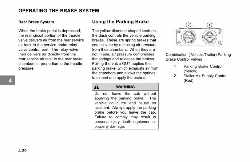
OPERATING THE BRAKE SYSTEM
Rear Brake System
When the brake pedal is depressed,the rear circuit portion of the treadlevalve delivers air from the rear serviceair tank to the service brake relayvalve control port. The relay valvethen delivers air directly from therear service air tank to the rear brakechambers in proportion to the treadlepressure.
Using the Parking Brake
The yellow diamond-shaped knob onthe dash controls the vehicle parkingbrakes. These are spring brakes thatyou activate by releasing air pressurefrom their chambers. When they arenot in use, air pressure compressesthe springs and releases the brakes.Pulling the valve OUT applies theparking brake, which exhausts air fromthe chambers and allows the springsto extend and apply the brakes.
WARNING
Do not leave the cab withoutapplying the parking brake. Thevehicle could roll and cause anaccident. Always apply the parkingbrake before you leave the cab.Failure to comply may result inpersonal injury, death, equipment orproperty damage.
Combination ( Vehicle/Trailer) ParkingBrake Control Valves
1 Parking Brake Control(Yellow)
2 Trailer Air Supply Control(Red)
4-20
4

OPERATING THE BRAKE SYSTEM
Before you leave the cab:
1. Apply all parking brakes. Pullout the Yellow Parking BrakeControl knob (1) located on thedash. The Red (octagon-shaped)Trailer Air Supply Control knob willautomatically pop out. (A dashwarning light will indicate when thebrake is ON.)
2. Shift the transmission into PARKposition:
° manual transmission, selectFirst or Reverse gear.
° automatic transmission, selectNeutral.
3. Turn the key to OFF.
4. Remove the key.
WARNING
Do not pull out the parking brakevalve while the vehicle is moving.Stopping with the parking brakecontrols can cause a sudden wheellock-up, loss of control, or over-takeby following vehicles. Failure tocomply may result in personalinjury, death, equipment or propertydamage.
The parking brakes act on the rearwheels only. They are spring-applied,with air pressure used to release them.Release air is supplied by both thefront and rear circuit air tanks througha double check valve.
To release the vehicle parkingbrakes ONLY:
• Push IN the Yellow knob on thedash. Your trailer will remainparked.
• Below 60 psi (414 kPa) the Yellowparking brake valve remains OUT(ON position). If air pressure is notrestored above 60 psi (414 kPa),the knob will automatically returnto the OUT position if you attemptto push it in. See Primary andSecondary Air Pressure on page3-61.
4-21
4
OPERATING THE BRAKE SYSTEM
To release the trailer brakes ONLY:
• Push IN the Red knob on the dash.The vehicle will remain parked.
To release the full combination ofbrakes:
• Push IN BOTH knobs on the dash.
• In the event that air pressure isreduced below a safe level: thelow air warning light will come onfirst; if air pressure continues todrop, the parking brake valve willpop OUT, automatically applyingthe spring brakes.
CAUTIONDo not try to put the vehicle in motionbefore pressure in the systemreaches 100 psi (689 kPa) becausethe wheels are locked by the springbrake action. Unnecessary stressand possible brake malfunctioncould occur if the vehicle is forced tomove before the air system reaches100 psi (689 kPa). Failure to complymay result in equipment damage.
WARNING
If the air pressure falls below 60psi (414 kPa) the spring brakesmay stop the vehicle abruptly,which could result in an accident.Observe the red warning lamps onthe gauges. If one comes on, donot continue to drive the vehicleuntil it has been properly repairedor serviced. Failure to comply mayresult in personal injury, death,equipment or property damage.
4-22
4
OPERATING THE BRAKE SYSTEM
WARNING
Do not use the trailer hand brakeor service brakes to park and holdan unattended vehicle, use theparking brakes. Because servicebrakes work with air pressure, thesebrakes could slowly release. Yourvehicle could roll, causing a seriousaccident. Never rely on the servicebrakes to hold a parked vehicle.Failure to comply may result inpersonal injury, death, equipment orproperty damage.
Vehicle/Trailer Air SupplyValveInitial Charge
The red octagon knob controls the airsupply to the trailer. With the systemcompletely discharged, both the Red(trailer air supply) and the Yellow(parking brake) knobs are OUT; thus,vehicle and the trailer parking (spring)brakes are applied.
To supply air to the trailer systemand release the trailer parkingbrakes:
1. Allow the vehicle air systempressure to build up to operatinglevel.
2. When system pressure reaches50 psi (345 kPa) the Red knobmay be pushed IN.
3. Hold the Red knob IN by handuntil the trailer air pressure buildsto a pre-set level, about 45 psi.
At this point it will remain in,charging the trailer system andreleasing only the trailer brakes.
4. The Yellow knob will remain OUT(vehicle brakes ON).
Normal Run Position
• The Yellow knob (system park)may now be pushed IN, which willsupply air to the vehicle springbrakes, releasing them.
4-23
4
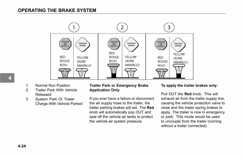
OPERATING THE BRAKE SYSTEM
1. Normal Run Position2. Trailer Park With Vehicle
Released3. System Park Or Trailer
Charge With Vehicle Parked
Trailer Park or Emergency BrakeApplication Only
If you ever have a failure or disconnectthe air supply hose to the trailer, thetrailer parking brakes will set. The Redknob will automatically pop OUT andseal off the vehicle air tanks to protectthe vehicle air system pressure.
To apply the trailer brakes only:
Pull OUT the Red knob. This willexhaust air from the trailer supply line,causing the vehicle protection valve toclose and the trailer spring brakes toapply. The trailer is now in emergencyor park. This mode would be usedto uncouple from the trailer (runningwithout a trailer connected).
4-24
4
OPERATING THE BRAKE SYSTEM
WARNING
Do not use the trailer hand brakeor service brakes to park and holdan unattended vehicle, use theparking brakes. Because servicebrakes work with air pressure, thesebrakes could slowly release. Yourvehicle could roll, causing a seriousaccident. Never rely on the servicebrakes to hold a parked vehicle.Failure to comply may result inpersonal injury, death, equipment orproperty damage.
System Park
With both knobs pushed in for normaloperating modes, the parking brakesof both the vehicle and the trailermay be applied by pulling the Yellowknob OUT. This will exhaust the airfrom the vehicle spring brakes, andsimultaneously cause the Red knob topop OUT, which will apply the trailerbrakes. This complies with the FederalMotor Vehicle Safety Standards(FMVSS) 121 requirement that onecontrol should apply all the parkingbrakes on the vehicle.
Trailer Charge
If both knobs are OUT (combinationvehicle is parked), and it is desired torecharge the trailer, the Red knob maybe pushed IN repressurizing the trailersupply line. The vehicle will remainparked. For more information on airsupply pressure requirements, seeInitial Charge on page 4-23.
4-25
4
OPERATING THE BRAKE SYSTEM
Brake Safety and Emergency
WARNING
Do not operate the vehicle in theevent of a malfunction in any aircircuit. The vehicle should not beoperated until the system is repairedand both braking circuits, includingall pneumatic and mechanicalcomponents, are working properly.Loss of system air can causethe service brakes to not functionresulting in the sudden applicationof the spring brakes causing wheellock-up, loss of control, or overtakeby following vehicles. Failure tocomply may result in personalinjury, death, equipment or propertydamage.
• If pressure is lost in the vehiclefront or rear circuit, the “check”valves isolate the unaffectedcircuit, allowing this circuit to
continue normal operation. Thetrailer brakes are still functional.
• If air pressure is lost in thetrailer supply/park circuit, and thepressure drops below 60 psi (414kPa), the trailer spring brakes areautomatically applied, and thevehicle air pressure circuits areunaffected.
• If air pressure is lost in the trailerbrake service circuit, and thepressure in the vehicle front andrear circuits drops below 60 psi(414 kPa), the vehicle and trailerspring brakes are automaticallyapplied.
Emergency Braking
WARNING
Unless you have an anti-lockbraking system (ABS), always avoidcompletely depressing the servicebrake pedal, if possible, even duringemergency braking. Depressing thebrake pedal too aggressively cancause the wheels to lock, which canlead to an uncontrolled skid andcan result in an accident. Failureto comply may result in personalinjury, death, equipment or propertydamage.
For Non-ABS Vehicles: to stop yourvehicle in an emergency, vary theservice brake application pressureto provide maximum braking forcewithout locking the wheels. Use enginecompression to assist the servicebrakes by not depressing the clutchpedal until the engine reaches idlespeed.
4-26
4
OPERATING THE BRAKE SYSTEM
Overheated Brakes
Under normal braking conditions, theenergy generated will bring the internalbrake drum temperature to about 500˚F (260˚ C). This is well within the safezone: the maximum safe temperatureof lining for drum type brakes is usuallyabout 800˚ F (427˚ C).
If service brakes are used foremergency braking, used improperly,or for prolonged periods, internal brakedrum temperatures may exceed 800˚F (427˚ C). Such brake overheatingmay be detected by a burning smellor smoke coming from a drum. If thisoccurs, you should immediately stopand check for cracked brake drums orlining fires. If neither exists, continuedriving and resume a slow speed assoon as possible to cool the brakes. Ifthe vehicle was to remain stopped, theheat transfer could destroy the liningsand distort the brake drum.
To prevent drums from distortionwhile they cool down:
• Park the vehicle on level surfaceand block the wheels.
• Release the parking brake andallow the brakes to cool down.See Parking Brake Valve on page3-92.
Anti-Lock Braking SystemIntroduction
North American on-highway Kenworthshave anti-lock braking system (ABS)as standard equipment. The ABSreduces the possibility of wheel lock-upduring hard braking. If a wheel is aboutto lock during braking, the ABS willautomatically adjust air pressure to thebrake chambers on the appropriatewheel(s) to prevent wheel lock-up.The ABS is automatically turned onwhen the ignition switch is turned on.See Anti-Lock Brake System (ABS) onpage 3-31.
WARNING
Do not rely on an anti-lockbrake system that is functioningimproperly. You could lose controlof the vehicle resulting in a severeaccident. Failure to comply mayresult in personal injury, death,equipment or property damage.
4-27
4

OPERATING THE BRAKE SYSTEM
NOTE
If your ABS lamp goes on whileyou are driving or stays on after thepower-on test, your anti-lock systemmight not be working. The ABS maynot function in an emergency. Youwill still have conventional brakes,but not anti-lock brakes. If the lampindicates a problem, have the ABSchecked
NOTE
Important Safety Reminders
• ABS does not reduce the timeor distance it takes to stopthe vehicle, it only helps withsteering control during braking.You should always maintain asafe following distance from othervehicles.
• ABS will not prevent a skid thatresults from changing directionabruptly, such as trying to takea corner too fast or making asudden lane change. Alwaysdrive at a safe, prudent speed forthe road and weather conditions.
• ABS cannot prevent a lossof stability. Always steermoderately when you are brakinghard. Severe or sharp steeringwheel movement can still causeyour vehicle to veer into oncomingtraffic or off the road.
Wheel Spin Control (option)
Your ABS may have the optionalAcceleration Slip Regulation(ASR)/Automatic Traction Control(ATC) feature. This feature ismonitored by a wheel spin control ASRWarning Lamp. See the appropriatevehicle section in this manual fordetails. This feature helps improvetraction when vehicles are on slipperysurfaces by reducing drive wheeloverspin. Wheel spin control worksautomatically in two different ways:
• If a drive wheel starts to spin,wheel spin control applies airpressure to brake the wheel. Thistransfers engine torque to thewheels with better traction.
• If all drive wheels spin, wheel spincontrol reduces engine torque toprovide improved traction.
4-28
4
OPERATING THE BRAKE SYSTEM
Wheel spin control turns itself on andoff, you do not have to select thisfeature. If drive wheels spin duringacceleration, the ASR Warning Lampcomes on, indicating wheel spin controlis active.
Do not allow the ASR Warning Lampto remain on continuously for anextended length of time. Extended,continuous use of the ASR/ATC cancause overheating of the drive wheelbrakes.
Deep Snow and Mud Switch (option)
A deep snow and mud switch isincluded with Wheel Spin Control. TheDeep Snow and Mud feature is helpfulduring acceleration This functionincreases available traction on extrasoft surfaces like snow, mud or gravel,by slightly increasing the permissiblewheel spin. When this function is inuse, the ASR Warning Lamp blinkscontinuously.
Off-Road ABS Function Switch(option)
Your Kenworth vehicle may beequipped with a separate switch toactivate an Off-Road ABS function.This function is NOT to be usedfor On-Highway driving but isintended to be used to improvestopping performance in Off-Highwayconditions (e.g. loose gravel andmud). The Off-Road ABS function isaccomplished by allowing a “wedge”of material to build-up in front ofmomentarily locked wheels.
Features and Benefits
• Changes the ABS control limits toallow for a more aggressive ABSfunction while off-road.
• Improves vehicle control andhelps reduce stopping distancesin off-road conditions or on poor
4-29
4
OPERATING THE BRAKE SYSTEM
traction surfaces such as loosegravel, sand and dirt.
• Allows retarders to functionindependently of the ABS function.
• If your vehicle does not have anengine retarder, the Off- RoadABS switch will function the same.
CAUTIONNever drive your vehicle onimproved roads/highways with theOff-Road ABS function turned on.When you drive your vehicle onto animproved road surface or highway,immediately turn off the Off-RoadABS switch. Failure to do sowill cause the ABS system to notfunction properly in an ABS eventunder 25 mph and could result in anaccident or personal injury.
WARNING
While the off-road mode canimprove vehicle control andshorten stopping distances, somesteering ability may be reducedon certain surfaces resulting fromthe momentarily sliding tires.Always operate your vehicle at safeoperating speeds. Failure to do somay cause you to lose control ofthe vehicle and could result in anaccident or personal injury.
How The Off-Road ABS FunctionWorks
• The ABS lamp flashes slowlyduring off-road mode engagement.This is done to alert you of amodification to the ABS controlsoftware.
• At speeds above 25 mph, the ABScontroller operates in the normalon-highway mode.
• At speeds between 10 and 25mph, the ABS control software ismodified to allow short periods(0.25 seconds) of locked-wheelcycles.
• At speeds below 10 mph, the ABScontrol software is turned off toallow locked wheels.
• When the Off-Road ABS functionis enabled, the Retarder Disableoutput is turned off. That is,the engine retarders are left tofunction without ABS intervention.For additional information, see theOff-Road ABS pamphlet in yourvehicle’s glove box.
4-30
4
OPERATING THE BRAKE SYSTEM
Trailer ABSPower Line Communication (PLC)
North American on-highway Kenworthsare equipped with a separate electricalcircuit to power the anti-lock brakesystem (ABS) on towed vehicle(s).In most cases, the ABS power willbe supplied through the Auxiliarycircuit on the primary 7- way trailerlight line connector. If the vehiclewas manufactured with a switchableAuxiliary circuit for trailer accessories,an additional 7-way connector wouldhave been provided for trailer ABSpower. In either case, the ABSpower line on the vehicle will be PLCequipped.
CAUTIONDo not splice into the non-switchableAuxiliary circuit on the primary 7-waytrailer light line. Doing so maycause the trailer ABS to malfunction.This circuit is dedicated for trailerABS power. To add a switchableauxiliary circuit, contact a KenworthDealership.
Vehicles and trailers built after3/1/01 must be able to turn on anIn-Cab Trailer ABS Warning Lamp(per Federal Motor Vehicle SafetyStandards (FMVSS) 121). The industrychose Power Line Communication(PLC) as the standard method to turnit on.
NOTE
Trailers not equipped with PLC cannot turn on the In-Cab Trailer ABSWarning Lamp.(There is one optionthat is an exception to this rule.See Special Trailer ABS (WithoutPLC) Option in the Anti-lock BrakingSystem section on page 4-27 fordetails.)
NOTEFor doubles or triples, the lamp doesnot distinguish between trailers. AnABS problem in any of the trailerswill activate the Trailer ABSWarningLamp.
4-31
4
OPERATING THE BRAKE SYSTEM
NOTE
If you change the intended servicein anyway (i.e. number of axles,multiple trailers, add switchabletrailer accessories, etc.) from thedate the vehicle was manufactured,you should contact your trailermanufacturer and/or trailer anti-lockbrake manufacturer to determine ifthe power available at the 7-waytrailer light line is adequate. Failureto do so might result in insufficientpower to the trailer ABS systemwhich may affect its operation.
CAUTION
The center pin of the 7-way trailerlight line may be constantly poweredfor ABS. Make sure it will notaccidently turn on trailer equipment.
Special Trailer ABS (Without PLC)Option
If a trailer does not have PLC, butit does have ABS that is poweredthrough an optional second trailerconnector (ISO 3731) and that trailerABS is designed to control the TrailerABS Warning Lamp in the cab andthe vehicle has been ordered with theoption to turn on this lamp for thesetypes of trailers, then this lamp will turnon when that trailer ABS has a systemproblem. This should be checked by aKenworth Dealer as soon as possible.The Trailer ABS Warning Lamp willnot turn on for the power-on test whenconnected to these types of trailers.
NOTE
Very few trailers built before 3/1/01have this option. Trailers built after3/1/01 are built with PLC technology.
Trailer Brake Hand Valve
This hand valve provides air pressureto apply the trailer brakes only. Itoperates independently of the foottreadle valve.
To operate the trailer brake handvalve:
• Pull down on the lever under theright side of the steering wheel.See Steering Column And Mirrorson page 3-100.
• The valve is self-returning. Whenpressure is removed from thevalve lever, it will return to the OFFposition.
NOTEThe trailer brake is not to be used asa substitute for the service brakes.Using this brake frequently, insteadof using the foot brake, will cause thetrailer brakes to wear out sooner.
4-32
4
OPERATING THE BRAKE SYSTEM
WARNING
Do not use the trailer hand brakeor service brakes to park and holdan unattended vehicle, use theparking brakes. Because servicebrakes work with air pressure, thesebrakes could slowly release. Yourvehicle could roll, causing a seriousaccident. Never rely on the servicebrakes to hold a parked vehicle.Failure to comply may result inpersonal injury, death, equipment orproperty damage.
Driving With an UnloadedTrailer
Do not use the engine retarder (suchas an exhaust brake) to slow thevehicle down when you are pulling anempty trailer.
WARNING
Do not use an engine retarder whenyou are driving with an unloadedtrailer. Using engine retarderswith an unloaded trailer can causea wheel lockup resulting in lesscontrol and/or jackknife. Whenyou are unloaded, you can have aserious accident if your wheels locksuddenly during braking. Failureto comply may result in personalinjury, death, equipment or propertydamage.
Engine Retarders
WARNING
The engine retarder isNOT intendedas the primary brake for the vehicle,nor is it an emergency brake. Theengine retarder only helps theservice brakes by using pressure toslow the drivetrain. Use the servicebrakes for quick stops. DO NOT relyonly on the engine retarder. Failureto comply may result in personalinjury, death, equipment or propertydamage.
4-33
4
OPERATING THE BRAKE SYSTEM
WARNING
Do not operate the engine retarderwhen driving/operating your vehicleon road surfaces with poor traction(wet, icy, or snow covered roads) orin heavy traffic. Braking caused bythe normal operation of the engineretarder could cause you to losecontrol of the vehicle resulting inan accident. Failure to complymay result in personal injury, death,equipment or property damage.
NOTEThe exhaust brake and engine brakeare two types of engine retarders.See your Engine Operation andMaintenance Manual and EngineRetarder or Engine Brake OperationManual for further details on usingthese types of engine retarders.
A variety of engine retarders orexhaust brakes may be installed (as
an option) to create a braking effecton the drive wheels. These devicesuse your engine's power to slow yourvehicle down. Because they canhelp keep your vehicle's brakes fromoverheating, they save wear and tearon the service brakes. However, theretarder is not an emergency brake.
Ideally (on normal road surfaces),you should slow your vehicle withthe retarder (where permitted by law)and use the service brakes only forstopping completely. Operating thisway will greatly prolong the life of thebrakes.
Exhaust Brake
With the exhaust brake switch ON, thebrake automatically creates its brakingeffect when you remove your foot fromthe accelerator pedal.
The brake switch is located on theaccessory dash panel. It controlswhether the brake is ON (ready to slowthe vehicle down) or OFF (no brakingaction).
• Do not use the engine retarder(such as an exhaust brake) toslow the vehicle down when youare pulling an empty trailer. SeeEngine Brakes for further details.
4-34
4
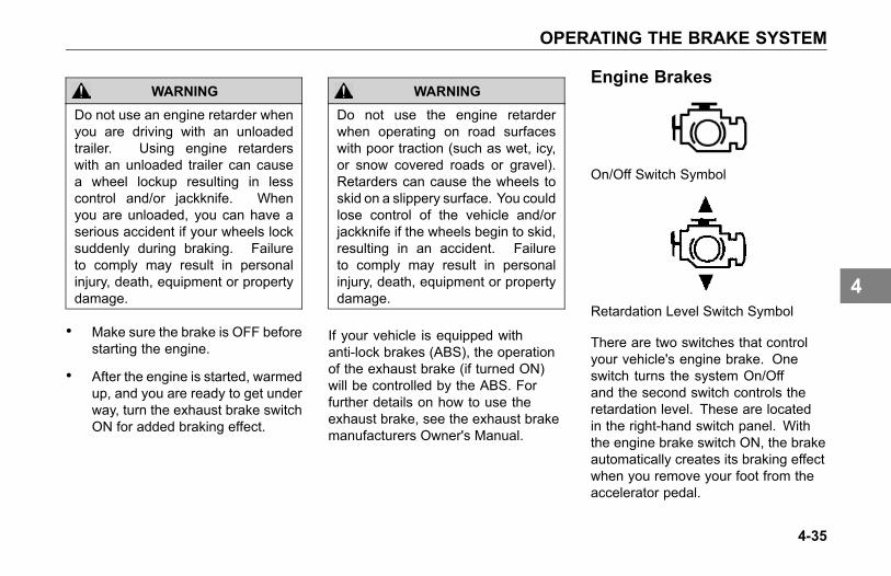
OPERATING THE BRAKE SYSTEM
WARNING
Do not use an engine retarder whenyou are driving with an unloadedtrailer. Using engine retarderswith an unloaded trailer can causea wheel lockup resulting in lesscontrol and/or jackknife. Whenyou are unloaded, you can have aserious accident if your wheels locksuddenly during braking. Failureto comply may result in personalinjury, death, equipment or propertydamage.
• Make sure the brake is OFF beforestarting the engine.
• After the engine is started, warmedup, and you are ready to get underway, turn the exhaust brake switchON for added braking effect.
WARNING
Do not use the engine retarderwhen operating on road surfaceswith poor traction (such as wet, icy,or snow covered roads or gravel).Retarders can cause the wheels toskid on a slippery surface. You couldlose control of the vehicle and/orjackknife if the wheels begin to skid,resulting in an accident. Failureto comply may result in personalinjury, death, equipment or propertydamage.
If your vehicle is equipped withanti-lock brakes (ABS), the operationof the exhaust brake (if turned ON)will be controlled by the ABS. Forfurther details on how to use theexhaust brake, see the exhaust brakemanufacturers Owner's Manual.
Engine Brakes
On/Off Switch Symbol
Retardation Level Switch Symbol
There are two switches that controlyour vehicle's engine brake. Oneswitch turns the system On/Offand the second switch controls theretardation level. These are locatedin the right-hand switch panel. Withthe engine brake switch ON, the brakeautomatically creates its braking effectwhen you remove your foot from theaccelerator pedal.
4-35
4
OPERATING THE BRAKE SYSTEM
Depending on the engine, yourvehicle may be equipped with eithera 2-position or 3-position RetardationLevel Switch. If your vehicle has thetwo-speed system, you can selectFULL or HALF. If it has the three-speedsystem, you can select LOW (1),MEDIUM (2), or HIGH (3) retarding.
See your Engine Operation andMaintenance Manual or Engine BrakeOperation Manual for further details onusing engine retarders.
Brake Components
The following is a brief description ofthe air/brake system. It is intended tosupply you with general information onhow the system works.
Compressor: supplies air to thesystem. System pressure is controlledby the governor.
Governor: controls the air pressurein the system by actuating thecompressor discharge mechanism. Itscut-out pressure is 115 to 125 psi (793to 862 kPa). Its preset cut-in pressureis set to between 13 to 25 psi (90 to172 kPa) below the cut-out pressuresetting (cut-out and cut-in interval isnot adjustable).
Safety Valve: installed on the supplyair tank outlet. It should vent off at 150psi (1034 kPa) permitting air to escape.
Air Dryer: collects and removesmoisture and contaminants from theair as it travels from the compressorto the wet tank.
Compressed Air Tanks: The wettank receives air from the air dryer andcools it somewhat, allowing moistureto condense for draining. Relativelydry air is then supplied to the twoservice air tanks for distribution to theirrespective brake circuits. The serviceair tanks are isolated from each otherby check valves.
Dual Service Brake Treadle Valve:delivers air to the two service brakecircuits.
Double Check Valve: directs thehigher air pressure from either the rear(primary) or front (secondary) serviceair tank to the modulating valve.
4-36
4

OPERATING THE BRAKE SYSTEM
Modulating Valve (SR-1): used onlyon full trucks, not tractors, performsfour functions:
• Limits spring brake hold-off airpressure delivered to the springbrake chambers.
• Provides a quick release of airpressure from the spring brakechambers to speed spring brakeapplication.
• Modulates spring brake applicationin proportion to front serviceapplication in the event of a rearservice failure.
• Prevents compounding of serviceand spring applications.
Quick-Release Valve: speeds therelease of air from the brake chambers.When air is released, the air in thebrake chambers is exhausted atthe quick-release valve, rather than
exhausting back through the treadlevalve.
Single Check Valve: allows air flow inone direction only.
Parking Brake Valve:Yellowdiamond-shaped knob. It controls theapplication and release of the parking(spring) brakes of the vehicle or of thevehicle-trailer combinations. If the airsystem is being charged from zeropressure, the parking brake valve willnot hold in the release position until thesystem pressure exceeds 60 psi (414kPa), which is the pressure required tooverride the load of this valve's plungerreturn spring.
Trailer Supply Valve: The Redoctagonal-shaped knob protectsthe vehicle system; it functions inconjunction with the parking brakevalve (yellow). The trailer supplyvalve is responsible for synchronizingthe vehicle and trailer parking and
emergency brakes. If the air systemis being charged from zero pressure,the trailer supply valve will not hold inthe applied position until the systempressure exceeds 50 psi (345 kPa). Itautomatically pops out and exhaustsair if supply air pressure drops below60 psi (414 kPa).
Vehicle Protection Valve: Thefunctions of this valve are to (1) receiveall pneumatic signals pertinent to theoperation of the trailer brake system,(2) transmit these signals to the trailer,and (3) protect the vehicle air supplyin case of separation of the air linesconnecting the vehicle to the trailer.
4-37
4
OPERATING THE ENGINE
OPERATING THEENGINE
Introduction
For detailed information on startingand operating the engine, refer to theEngine Operation and MaintenanceManual provided with your Kenworth .
Because each vehicle iscustom-equipped, all engine operationinstructions presented in this sectionare general. You will want to consultthe engine manual to find out detailsabout your vehicle's specific engineneeds. You may need to use a slightlydifferent procedure from the oneoutlined here.
Also, read the American TruckingAssociation's (ATA) Truck Driver'sHandbook. It will give you tips onstarting, shifting, and driving yourvehicle.
This section includes instructions forboth Normal Temperature starting andCold Weather starting. The enginetype (brand) and size determines whattype of cold weather starting aid isinstalled in your vehicle. Refer to yourEngine Operation and MaintenanceManual to learn what precautionsyou should take before starting theengine. Many new electronic enginescannot use ether or other startingfluids. These engines are equippedwith a flame-start air intake heatingsystem. See Starting Procedure - ColdWeather on page 4-41.
WARNING
Do not use ether or starting fluidin conjunction with flame-start airintake heating systems. Flame-startsystems use an open flame insidethe manifold to heat the air/fuelmixture for cold weather starting. Ifether is also used with flame-start,the air/fuel will ignite inside themanifold, which could cause anexplosion. Failure to comply mayresult in personal injury, death,equipment or property damage.
4-38
4

OPERATING THE ENGINE
WARNING
Do not start or let the enginerun in an enclosed, unventilatedarea. Exhaust fumes from theengine contain carbon monoxide, acolorless and odorless gas. Carbonmonoxide can be fatal if inhaled.Failure to comply may result inpersonal injury or death.
CAUTIONDo not park or operate the vehicle inareas where the hot exhaust systemmay come in contact with dry grass,brush, spilled fuel or other materialthat can cause a fire.
Starting Procedure - NormalTemperature
Use the following procedure tostart your Kenworth when outsidetemperatures are at or ABOVE normalstarting temperatures. Check theEngine Operation and MaintenanceManual for starting temperatures.
1. Set the parking brake.
2. Insert key into ignition key switch.
3. Disable (or turn OFF) the followingsystems prior to starting theengine: the exhaust brake,dual-speed rear axle (put in LOW),and block heater (if equipped).
4. Disengage transmission: placeshift lever in the Neutral position.
5. Disengage (depress) the clutch(with manual transmission).
6. Turn the ignition switch tothe ON position. For normaltemperatures, no accelerator
advance is necessary. See Use ofAccelerator below. If the WAIT TOSTART indicator lamp activates toON, wait until the indicator lampcycles to OFF (approximately 60seconds) before attempting to startthe engine. (For each engine andambient temperatures, warm-upcycles will vary.)
7. Turn the ignition switch to theSTART position to engage thestarter. Crank the engine until itstarts. If the engine does not startwithin 30 seconds, release thekey.
• If your Kenworth is equipped withthe optional push button starterswitch, use it to engage the starter.
4-39
4
OPERATING THE ENGINE
Use of Accelerator
• For mild to warm temperaturesabove 60° F (16° C) keep yourfoot OFF the accelerator pedalwhile cranking. If the engine doesnot start after 5 seconds, apply fullthrottle while cranking.
• For below normal startingtemperatures fully depress theaccelerator (throttle) pedal afterengaging the starter.
NOTEPumping the accelerator will notassist in starting the engine.
CAUTIONTo help avoid overtaxing thestarter motor or batteries, orcausing engine damage, follow therecommendations listed below:
• Do not engage starter for morethan 30 seconds at a time.
• Wait 2 minutes between eachattempt to start the engine. Thisallows the starter motor to cooland time for the batteries to regainpower.
• If the engine fails to start aftera couple of tries, there could bea malfunction with the engine orother related system. Make anyadjustments or repairs necessarybefore trying to start the engineagain.
NOTE
Some starters are equipped withovercrank protection. Check theEngine Operation and MaintenanceManual for details.
When the engine starts:
• Watch the oil pressure gauge.Oil pressure should rise within15 seconds after the enginestarts. If the oil pressure doesnot rise, stop the engine. Findwhat is wrong before restarting.Check the Engine Operation andMaintenance Manual for the rightoil pressure for your vehicle'sengine. In most engines, idlepressure should be about 15 psi.
CAUTIONNever operate the starter motorwhile the engine is running. Thestarter and flywheel gears couldclash or jam. Failure to comply mayresult in equipment damage.
• Wait until normal engine oilpressure registers on the gaugebefore idling or accelerating theengine beyond 1,000 rpm.
4-40
4
OPERATING THE ENGINE
• Watch the primary and secondaryair pressure gauges. They shouldboth register 100 psi (689 kPa)before releasing the spring brakeand moving the vehicle. Also,check the alarm system for anytype of faults and correct thembefore moving the vehicle.
CAUTIONDo not try to put the vehicle inmotion before pressure in the airsystem reaches 100 psi (689 kPa)because the wheels will still belocked by the spring brake action.Unnecessary stress and possiblebrake malfunction could occur if thevehicle is forced to move before theair system reaches 100 psi (689kPa). Failure to comply may resultin equipment damage.
Starting Procedure - ColdWeather
In addition to the previous NormalStarting Procedures, use these ColdWeather Starting guidelines whenthe air temperature falls below acertain temperature. Check yourEngine Operation and MaintenanceManual for further details on when coldweather starting aids are needed.
Using special cold-starting equipmentwill help the engine start easier. Andin cold weather, fast engine startinghelps relieve the loads on the electricalsystem and cranking motor. If youfollow these few simple guidelines,you will extend the service life of yourvehicle's engine:
• Keep the electrical system in topcondition.
• Use the best quality andrecommended grade of fuel(see Engine Operation andMaintenance Manual).
• Use the recommended enginelubricating oil.
• As stated in the Normal StartingProcedures, when temperaturesare below normal, fully depress theaccelerator pedal after engagingthe starter.
4-41
4
OPERATING THE ENGINE
Engine Block Heater (Option)
To preheat the engine before starting,plug the optional engine block heaterinto a properly grounded AC electricalsource. Do not start the engine withthe heater plugged in.
WARNING
Engine block heaters can causefires resulting in personal injuryand/or property damage if notproperly maintained and operated.Regularly inspect the engine blockheater wiring and connector fordamaged or frayed wires. Do notuse the heater if there are anysigns of problems. Contact yourauthorized Kenworth Dealer or themanufacturer of the heater if you arein need of repairs or information.
CAUTION
Always unplug heater before startingthe engine. Damage to the coolingsystem could occur if the heater isnot turned OFF (unplugged).
Depending on engine make, when thetemperature falls below -10° F (-24°C), the block heater is required.
• Use a solution of half ethyleneglycol antifreeze and half waterfor best heater performance.Do not exceed 65 percentconcentration of antifreeze, as ashortened heater life will result.See COOLING SYSTEM on page5-60, for more information.
• After servicing the cooling system,operate the vehicle for a day or twobefore using the heater. Trappedair inside the engine needs timeto escape.
Engine Warm-Up and Idling
The purpose of engine warm-up isto allow an oil film to be establishedbetween pistons, shafts, and bearingswhile your engine gradually reachesoperating temperature.
4-42
4
OPERATING THE ENGINE
Warm-Up Procedure
1. After you have started the engine,idle the engine at approximately600 rpm while you check vitalengine systems:
° oil pressure
° air pressure
° alternator output
2. Before placing engine under aload, continue warm-up with theengine at 900 to 1,000 rpm for 3to 5 minutes.When a cold engine is started,increase the engine speed (RPM)slowly to be sure adequatelubrication is available to thebearings and to allow the oilpressure to stabilize. In extremelycold temperatures, you may haveto increase idle speed.
NOTEIn colder climates where thetemperatures are often belowfreezing, sufficient warm-up forturbocharged engines is especiallyimportant. Chilled external oillines leading to the turbochargerwill slow the oil flow until the oilwarms, reducing oil available forthe bearings. Watch the engine oiltemperature or pressure gauge fora warming trend before increasingengine idle speed (RPM).
3. Continue the engine warm-up untilthe coolant temperature reachesat least 130° F (54° C). At thistemperature, you can use partialthrottle. Wait until the coolanttemperature is at least 160° F (71°C) before operating at full throttle.See Transmission Warm-Up onpage 4-64.
WARNING
Exhaust fumes from the enginecontain carbon monoxide, acolorless and odorless gas. Do notbreathe the engine exhaust gas.A poorly maintained, damaged orcorroded exhaust system can allowcarbon monoxide to enter the cab.Entry of carbon monoxide into thecab is also possible from othervehicles nearby. Failure to properlymaintain your vehicle could causecarbon monoxide to enter the caband cause illness or death.
4-43
4
OPERATING THE ENGINE
WARNING
Never idle your vehicle for prolongedperiods of time if you sense thatexhaust fumes are entering the cab.Investigate the cause of the fumesand correct it as soon as possible.If the vehicle must be driven underthese conditions, drive only with thewindows open. Failure to repair thesource of the exhaust fumes maylead to personal harm.
NOTEKeep the engine exhaust systemand the vehicles cab ventilationsystem properly maintained.
It is recommended that the vehiclesexhaust system and cab be inspected:
• By a competent technician every15,000 miles
• Whenever a change is noticed inthe sound of the exhaust system
• Whenever the exhaust system,underbody or cab is damaged
NOTEDo not stay in the vehicle with theengine running or idling for morethan 10 minutes with the vehiclesHeater and A/C ventilation systemin RECIRC or a LOW fan speed.Even with the ventilation system On,running the engine while parked orstopped for longer periods of time isnot recommended. See Heater/AirConditioning Operating Instructionsfor system setting instructions.
NOTE
If other vehicles are parked next toyou idling, move your vehicle or donot stay in your vehicle for prolongedperiods of time
Winterfronts
A winterfront or other air flow restrictiondevice may be mounted in front ofthe radiator to increase cab heatertemperature in cold climates.
CAUTION
A winterfront should only be usedat temperatures below 40°F (4°C).Use of a winterfront above 40°F(4°C) can decrease life of coolingmodule components. Removewinterfront as soon as the ambienttemp reaches 41°F (5°C). The useof a winterfront above 40°F (4°C)can result in excessive enginecoolant, oil, and charge air (intake)temperatures, which can lead tooverheating and possible engineor coolant module damage andemissions non-compliance.
4-44
4
OPERATING THE ENGINE
NOTE
A Kenworth winterfront is designedto minimize the temperaturedifferences across the radiator andreduce the possibility of coolingmodule damage. Aftermarketwinterfronts may not provide theproper airflow distribution and couldcause cooling module damage.
Idling the Engine
Under most circumstances, idlingyour engine for long periods merelywastes fuel. In severe Arctic weatherconditions, however, you may needlonger idling to be sure all parts of yourengine are fully lubricated.
WARNING
To reduce the chance of death,personal injury, and/or vehicledamage from overheated engines,which can result in a fire, neverleave the engine idling without analert driver present. If the engineshould overheat, as indicated bythe engine coolant temperaturelight, immediate action is requiredto correct the condition. Continuedunattended operation of the engine,even for a short time, may result inserious engine damage or a fire.
CAUTIONDo not allow your engine to idle, atlow RPM's (400-600 rpm), longerthan five minutes. Long periodsof idling after the engine hasreached operating temperaturescan decrease engine temperatureand cause gummed piston rings,clogged injectors, and possibleengine damage from lack oflubrication. The normal torsionalvibrations generated can also causetransmission wear.
During the time it takes you to drink acup of coffee, your engine can cool asmuch as 60° F (33° C) below normaloperating temperature. To keep theengine warm during a short break, turnit off. Do not allow your engine to idlelonger than five minutes.
4-45
4
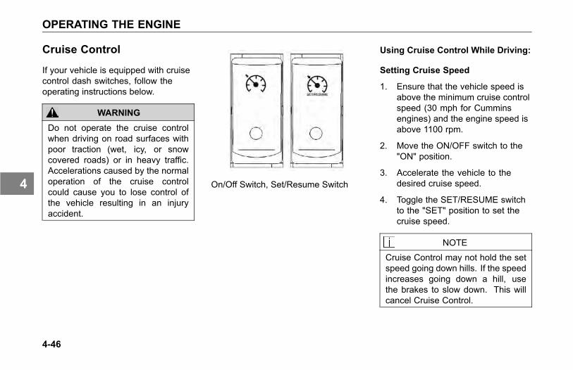
OPERATING THE ENGINE
Cruise Control
If your vehicle is equipped with cruisecontrol dash switches, follow theoperating instructions below.
WARNING
Do not operate the cruise controlwhen driving on road surfaces withpoor traction (wet, icy, or snowcovered roads) or in heavy traffic.Accelerations caused by the normaloperation of the cruise controlcould cause you to lose control ofthe vehicle resulting in an injuryaccident.
On/Off Switch, Set/Resume Switch
Using Cruise Control While Driving:
Setting Cruise Speed
1. Ensure that the vehicle speed isabove the minimum cruise controlspeed (30 mph for Cumminsengines) and the engine speed isabove 1100 rpm.
2. Move the ON/OFF switch to the"ON" position.
3. Accelerate the vehicle to thedesired cruise speed.
4. Toggle the SET/RESUME switchto the "SET" position to set thecruise speed.
NOTE
Cruise Control may not hold the setspeed going down hills. If the speedincreases going down a hill, usethe brakes to slow down. This willcancel Cruise Control.
4-46
4

OPERATING THE ENGINE
Changing the Cruise Set Speed
• To increase the cruise set speed;Hold the SET/ RESUME switch inthe "SET" position until the desiredspeed is achieved then releasethe switch.
• To decrease the cruise set speed;Hold the SET/ RESUME switch inthe "RESUME" position and coastto the desired lower speed thenrelease the switch.
Cancelling Cruise Control
You can cancel cruise control in anyof these ways:
• Tap the brake pedal.
• Tap the clutch pedal.
• Move the ON/OFF switch to the"OFF" position.
Resuming Cruise Control
1. If you tapped the brake orclutch pedal, the cruise/idlecontrol remembered thepreviously set cruise speed.To resume that set speed,accelerate above the minimumcruise control speed and;Toggle the SET/RESUME switchto the "RESUME" position.
2. If you moved the ON/OFF switchto the "OFF" position or turned theignition key OFF, this cleared thesystem memory and you will needto set a new cruise speed.
Using Cruise Control for StationaryPTO Operation:
Setting Idle Speed
1. Ensure parking brakes are applied.
2. Ensure transmission is in Neutral.
3. Engage PTO per themanufacturer's operatinginstructions.
4. Move the ON/OFF switch to the"ON" position.
5. Toggle the SET/RESUME switchto obtain the desired engine rpm.
Cancelling Cruise Control
You can cancel cruise control in anyof these ways:
• Tap the brake pedal.
• Tap the clutch pedal.
• Move the ON/OFF switch to the"OFF" position.
4-47
4
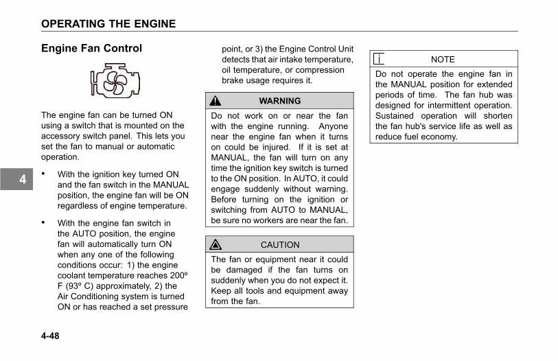
OPERATING THE ENGINE
Engine Fan Control
The engine fan can be turned ONusing a switch that is mounted on theaccessory switch panel. This lets youset the fan to manual or automaticoperation.
• With the ignition key turned ONand the fan switch in the MANUALposition, the engine fan will be ONregardless of engine temperature.
• With the engine fan switch inthe AUTO position, the enginefan will automatically turn ONwhen any one of the followingconditions occur: 1) the enginecoolant temperature reaches 200ºF (93º C) approximately, 2) theAir Conditioning system is turnedON or has reached a set pressure
point, or 3) the Engine Control Unitdetects that air intake temperature,oil temperature, or compressionbrake usage requires it.
WARNING
Do not work on or near the fanwith the engine running. Anyonenear the engine fan when it turnson could be injured. If it is set atMANUAL, the fan will turn on anytime the ignition key switch is turnedto the ON position. In AUTO, it couldengage suddenly without warning.Before turning on the ignition orswitching from AUTO to MANUAL,be sure no workers are near the fan.
CAUTION
The fan or equipment near it couldbe damaged if the fan turns onsuddenly when you do not expect it.Keep all tools and equipment awayfrom the fan.
NOTE
Do not operate the engine fan inthe MANUAL position for extendedperiods of time. The fan hub wasdesigned for intermittent operation.Sustained operation will shortenthe fan hub's service life as well asreduce fuel economy.
4-48
4
OPERATING THE ENGINE
Engine Control Display
Your Kenworth may come withan optional Engine and DriverInformation Display. This instrumentrecords information on enginediagnostics, scheduled maintenance,driving conditions, and general tripinformation. The specific featuresof your display may vary dependingon engine make. For completeinformation on the display see theengine manufacturer's manual.
Engine Shutdown System
This system is an option with eachengine. The engine shutdown systemcontinually monitors oil pressure andengine temperature. If either conditionchanges beyond the normal range ofoil pressure or temperature readings,the engine shuts down automatically,sounding the alarm and turning awarning light on. The buzzer will soundcontinuously as long as Stop Engineindicator is on.
After the engine starts, and until oilpressure reaches normal operatingpressures, a warning alarm will sound.As soon as oil pressure increases, thebuzzer turns off automatically. If theengine shuts down automatically or ifthe buzzer and light turn on while theengine is running, have your engineserviced at an authorized KenworthDealer.
Each shutdown system is enginespecific; therefore to learn howthis system works on your vehicle,you should consult the enginemanufacturer's manual.
4-49
4

OPERATING THE REAR/DRIVE AXLE
OPERATING THEREAR/DRIVE AXLE
Introduction
This section covers the operationof your Rear/Drive Axle. Theseinstructions apply to the most commonfeatures of drive axles. Refer to themanufacturers instructions for furtherinformation on the operation of youraxle.
Inter-Axle Differential Lock
The inter-axle differential allows eachaxle to turn independently, whichrelieves stress on the rear axles andreduces tire wear. A switch on theaccessory switch panel locks theinter-axle differentials, which gives youbetter traction for slippery surfaces.You will notice that the switch has aguard to protect you from activating itaccidentally.
When to Use the Differential Lock
In the LOCK position, an air operatedclutch positively locks both sets ofaxles together, providing greatertraction on slippery road surfaces;however, steering around cornersand on dry pavement is more difficult.Continuous operation on a paved, drysurface stresses the tandem axles,possibly causing internal damage.
Only use this feature when driving onsurfaces with poor traction, such asheavy mud or snow, or loose gravel.And do not use it when going downhillor at speeds greater than 25 mph (40km/h).
4-50
4
OPERATING THE REAR/DRIVE AXLE
Lock the differential when youencounter road conditions such asthese:
• Ice or snow, with or without tirechains.
• Dirt roads.
• Loose sand, mud, or other off-roadconditions.
WARNING
Do not put the differential lock in theLOCK position while the wheels arespinning freely (slipping), you couldlose control of the vehicle or causeaxle damage. Switch to LOCK onlywhen the wheels are not spinning.Failure to comply may result inpersonal injury, death, equipment orproperty damage.
• Look ahead for wet, muddy, or icypatches on the road, stop your
vehicle and switch to LOCK aheadof time.
WARNING
Do not operate the vehicle ondry pavement with the differentiallocked, this could lead to anaccident. On dry pavement, youwill not be able to steer well withthe differential locked. Lock thedifferential only when operating onsurfaces with poor traction, such aswet, slippery roads or loose gravel.Failure to comply may result inpersonal injury, death, equipment orproperty damage.
Inter-Axle Differential LockOperation
WARNING
Do not use the differential lockduring downhill operation or atspeeds above 25 mph (40 km/h).When it is engaged under theseconditions, your vehicle will exhibitundersteer handling characteristics.This understeer condition will causeyour vehicle to not turn as quicklyand more steering effort will berequired, which can cause anaccident. Failure to comply mayresult in personal injury, death,equipment or property damage.
4-51
4
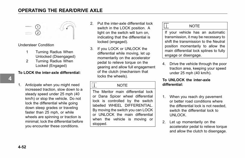
OPERATING THE REAR/DRIVE AXLE
Understeer Condition
1 Turning Radius WhenUnlocked (Disengaged)
2 Turning Radius WhenLocked (Engaged)
To LOCK the inter-axle differential:
1. Anticipate when you might needincreased traction, slow down to asteady speed under 25 mph (40km/h) or stop the vehicle. Do notlock the differential while goingdown steep grades or travelingfaster than 25 mph, or whilewheels are spinning or traction isminimal; lock the differential beforeyou encounter these conditions.
2. Put the inter-axle differential lockswitch in the LOCK position. Alight on the switch will turn on,indicating that the differential islocked (engaged).
3. If you LOCK or UNLOCK thedifferential while moving, let upmomentarily on the acceleratorpedal to relieve torque on thegearing and allow full engagementof the clutch (mechanism thatlocks the wheels).
NOTE
The Meritor main differential lockor Dana Spicer wheel differentiallock is controlled by the switchlabelled WHEEL DIFFERENTIAL.By moving the switch you can LOCKor UNLOCK the main differentialwhen the vehicle is moving orstopped.
NOTE
If your vehicle has an automatictransmission, it may be necessary toshift the transmission to the Neutralposition momentarily to allow themain differential lock splines to fullyengage or disengage.
4. Drive the vehicle through the poortraction area, keeping your speedunder 25 mph (40 km/h).
To UNLOCK the inter-axledifferential:
1. When you reach dry pavementor better road conditions wherethe differential lock is not needed,switch the differential lock toUNLOCK.
2. Let up momentarily on theaccelerator pedal to relieve torqueand allow the clutch to disengage.
4-52
4
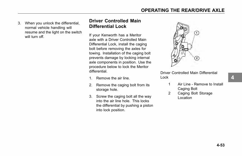
OPERATING THE REAR/DRIVE AXLE
3. When you unlock the differential,normal vehicle handling willresume and the light on the switchwill turn off.
Driver Controlled MainDifferential Lock
If your Kenworth has a Meritoraxle with a Driver Controlled MainDifferential Lock, install the cagingbolt before removing the axles fortowing. Installation of the caging boltprevents damage by locking internalaxle components in position. Use theprocedure below to lock the Meritordifferential.
1. Remove the air line.
2. Remove the caging bolt from itsstorage hole.
3. Screw the caging bolt all the wayinto the air line hole. This locksthe differential by pushing a pistoninto lock position.
Driver Controlled Main DifferentialLock
1 Air Line - Remove to InstallCaging Bolt
2 Caging Bolt StorageLocation
4-53
4
OPERATING THE REAR/DRIVE AXLE
Dual Range (Two-Speed)Rear Axle
Your vehicle may be equipped with atwo-speed or dual range axle (option).You can select two rear axle ratios foroperating under heavy loads or roughterrain as well as for over the roadhauling.
The Low Range provides maximumtorque for hauling heavy loads ortraveling over rough terrain. The HighRange is a faster ratio for highwayspeeds and general over the roadconditions. A switch on the accessoryswitch panel controls the Dual RangeRear Axle. You will notice that theswitch has a guard to protect you fromactivating it accidentally. Always parkyour vehicle with the range selector inLOW.
Dual Range Axle Operation
Important tips on operating a DualRange Axle with Interaxle Differential:
1. Shift the axle with the inter-axledifferential in the unlocked positiononly.
2. When you are driving with poortraction, lock the differential. Whenyou have the differential locked,drive with the axle in LOW rangeonly.
3. When you are driving on a surfacewith good traction, keep theinteraxle differential unlocked. Youcan drive with the axle in the LOWor HIGH range.
4. Always UNLOCK the inter-axledifferential before shifting the axlespeed range.
CAUTION
If you shift the axle range with theinter-axle differential in LOCK, youcould seriously damage the axles.Never shift the axle range with thedifferential locked.
4-54
4
OPERATING THE REAR/DRIVE AXLE
Starting-Up
1. Unlock the inter-axle differentialbefore starting.
2. Put the Range Selector in theLOW range. Shift the transmissionto start the vehicle moving.
3. When you are driving on roughterrain and secondary roads, orunder a very heavy load, keep theaxle in the LOW range. Shift thetransmission to maintain properroad speed.
WARNING
Never shift the axle when movingdown hill. Engine drivelinedisengagement may occur,eliminating engine retardation andallowing the wheels to spin fasterthan the current speed of the engine.This may require severe braking toslow the vehicle down and can resultin an accident. Failure to complymay result in personal injury, death,equipment or property damage.
Proper shifting of the axle depends onthe synchronization of engine/drivelineand wheel speed. When you shiftthe axle, the connection between theengine and wheels is momentarilydisengaged while the gearing issynchronized. Normally when the axleis shifted the speed of the engine, axle,and wheels adjust, allowing for propergear engagement.
When going down hill the wheels willnot slow down, but will tend to speedup, which makes gear synchronizationalmost impossible. As a result, theaxle is neither in HIGH nor LOW rangeand all engine/driveline retardation islost. Without engine retardation it ismore difficult to slow the vehicle downand greater stress is put on the brakesystem.
CAUTION
To avoid damaging your vehicle shiftthe axle at slower travel speeds untilyou are used to driving with a dualrange axle.
4-55
4
OPERATING THE REAR/DRIVE AXLE
LOW to HIGH (Cruising)
When you go from rough terrain tohighway driving, shift the axle to theHIGH range following this procedure:
1. Be sure the differential isUNLOCKED.
2. Maintain your vehicle speed(accelerator depressed) and movethe Range Selector lever to HIGH.
3. Keep driving with the acceleratordepressed until you want the axleto shift.
4. To make the axle shift, release theaccelerator until the axle shifts.You are now in the HIGH axlerange for highway speeds. Shiftthe transmission normally to reachyour desired cruising speed.
HIGH to LOW (Rough Terrain)
If you need to downshift the axle formore power or you are driving onrough terrain:
1. Maintain your vehicle speed(accelerator depressed) and movethe Range Selector lever to LOW.
2. Keep driving with the acceleratordepressed until you want the axleto downshift.
3. To make the axle downshift,release and depress theaccelerator quickly to increase theengine RPM. The axle will shift toLOW range.
4. You are now in the LOW axlerange for rough terrain and heavyloads. Shift the transmissionnormally to maintain the desiredspeed.
Auxiliary Axles - Pusher orTag
Adjustable auxiliary axles can addto the productivity of your vehicle. Itis important to recognize that whenadjustable auxiliary axles are notdeployed while the vehicle is carryinga load, excessive loads may be forcedonto other vehicle components (frame,axles, suspension, brakes, steering,tires, etc.). This overload conditionmay reduce the service life of thesevehicle components. Acceptableservice life is maintained throughcareful operation, proper maintenanceand proper adherence to the vehiclesand auxiliary axle manufacturersoperating limits.
4-56
4

OPERATING THE REAR/DRIVE AXLE
If your vehicle is equipped withfactory-installed pusher or tagaxle(s), or you have a third-party (i.e.body-builder) install these axles, it isyour responsibility to ensure that theaxle lift controls or air-dump valve (ifequipped) are calibrated prior to puttingthe vehicle into service. The reasonfor doing this important calibration is toobtain the proper axle load distributionfor the entire vehicles axles. As withthe entire vehicles axles, the pusheror tag axle load cannot exceed thecertified GAWR and/or the legal loadlimit of the axle assembly and itsrelated components.
There are three types of pusher or tagaxles:
• Liftable/steerable (axle liftcalibration required)
• Liftable/non-steerable (axle liftcalibration required)
• Non-liftable (some suspensionsrequire dump valve calibration)
Functionality of Auxiliary Axlesinstalled by Kenworth
• Any liftable steerable auxiliaryaxles installed by Kenworth willraise when the parking brake isengaged.
• Any liftable steerable auxiliaryaxles installed by Kenworth willraise when the vehicle is placedinto reverse.
• Liftable/non-steerable axles donot raise when parking brake isengaged or if vehicle is in reverse.
4-57
4
OPERATING THE REAR/DRIVE AXLE
WARNING
Do not operate or park thevehicle with auxiliary axles inthe down/loaded position whenvehicle is unladen, or is beingunloaded. Raise or dump air intodriver-controlled auxiliary axle(s)prior to unloading vehicle. Failureto do so can result in loss of vehiclecontrol or rollaway that may result inpersonal injury, death, equipment orproperty damage.
CAUTION
Never exceed the manufacturersassigned gross axle weight ratings(GAWR) of each axle when theauxiliary axles are downloaded.Never exceed the manufacturerscreep ratings when operatingwith a load when the auxiliaryaxles are unloaded. Refer toyour vehicles compliance decalslocated on the LH doorjamb forthe maximum allowable load foreach axle. Exceeding the specifiedweight rating of any axle can causeequipment damage.
NOTE
Axle Creep Ratings are assignedby the axle manufacturer and arebased on axle model and intendedservice of the vehicle. To find outwhat the allowable creep rating isfor your vehicle, contact the nearestauthorized Kenworth Dealer or axlerepresentative.
4-58
4
OPERATING THE REAR/DRIVE AXLE
Axle Creep Rating DefinitionCreep Ratings
Low speed, off-highway (work site)axle loads, which exceed the standardgross axle weight rating (GAWR) of aparticular axle.
Operator's using vehicles equippedwith liftable auxiliary axles mustconsider creep ratings when anyliftable axle is unloaded or in the raisedposition. Liftable auxiliary axles shouldonly be raised (or unloaded) to improvemaneuverability in an off-road use orwhen vehicle is unloaded.
NOTE
Axle Creep ratings MUST NOT beexceeded.
Contact your Kenworth Dealer oraxle manufacturer to determine whatthe creep rating is for your particularaxle(s) and configuration. Creep
ratings are generally limited to thefollowing:
• Tandem rear axles only
• Straight trucks only
• Maximum spring mountcenters per axle manufacturersspecifications
• Maximum tire static loaded radius(SLR) per axle manufacturersspecifications
CAUTIONAlways lower the axles as soonas possible after receiving a load.Never exceed 5 miles per hour whendriving with a load with the auxiliaryaxle(s) raised/unloaded. Failure tolower the axle(s) can overload theframe and remaining axles, andcould cause equipment damage.
WARNING
Never operate the vehicle withmore pressure in the lift axles thanis necessary to carry the load,as determined by the calibrationprocedure described. Failure to doso can result in loss of traction andstability at the steer and/or driveaxles and can result in increasedbraking distance which could causeloss of vehicle control resulting inan accident. Failure to complymay result in personal injury, death,equipment or property damage.
CAUTION
Do not modify the air system and/orcontrol functionality on a factoryinstalled auxiliary axle(s). Modifyingthe factory operation of the pusherand/or tag axle(s) will void yourwarranty, and can cause equipmentdamage.
4-59
4
OPERATING THE REAR/DRIVE AXLE
CAUTIONA change in tire size on either theauxiliary axles or the drive/steeraxles can change the calibrationof the auxiliary axles. If tires areinstalled with a different loadedradius, the calibration proceduremust be repeated. Failure to do socan cause equipment damage.
Liftable/Steerable orLiftable/Non-Steerable Pusherand/or Tag Axle CalibrationProcedure
Below are some general instructionson how to adjust and calibrate the aircontrol valve for the auxiliary axles toobtain the proper load distribution ofthe axle(s). For additional operatingand maintenance instructions, see thepusher or tag suspension manufacturerliterature in the glove box or contactthem directly.
NOTE
This procedure must be performedprior to placing the vehicle intoservice.
Setting the Pressure-to-Load Ratio
To obtain the desired axle loaddistribution, you must correlate thesuspension air gauge pressure to theactual axle load by scaling the axleweight(s) and adjusting the pressureto obtain the desired load. Once thedesired load or load range is achieved,document the pressure-to-load ratio orsetting for future use.
4-60
4
OPERATING THE REAR/DRIVE AXLE
General Calibration Guidelines
These instructions are general innature. For more specific instructions,review the pusher or tag suspensionmanufacturers maintenance manual orcontact the nearest authorized dealer.
NOTE
Perform this procedure at or neara weight scale. Procedure canbe performed while parked on theweight scale if scale is available.
1. Park loaded vehicle on levelsurface with wheels blocked.
2. Release vehicles springbrakes. (Do not release forLiftable/Non-Steerable pusher ortag axles).
3. Lower the pusher/tag axles withthe axle lift control flip valve. (Forsome non-liftable axles, inflate airsuspension).
4. Adjust the amount of load oneach axle by turning the pressureregulator clockwise to increasethe load or counterclockwiseto decrease the load. (Thesuspension manufacturermay publish pre-establishedPressure-to- Load Ratio PressureSettings to assist you in achievingan estimated ground load).
5. After setting the pressure to obtainthe desired axle load, verify properground loading with the weightscale.
NOTE
Exceeding local, state or federalweight limits may result in citations.Contact your local commercialweight enforcement office for limitsin your area.
Operation guidelines
NOTE
Steerable-pusher and/or tag axle(s)will raise when the transmission isshifted into reverse or when theparking brakes are applied.
4-61
4
OPERATING THE REAR/DRIVE AXLE
Maximizing Drive Axle Traction
Adjust the pressure regulator controlknob to a lower pressure until desiredtraction is obtained. By reducing airpressure at pusher or tag axle, loadwill be transferred to drive axles. Donot overload drive axles.
Coupling To A Loaded Trailer
Inflate air springs of the auxiliary axlesto the desired pressure after couplingto a loaded trailer while still maintainingproper traction of the drive axles.
Unloading Operation
Always deflate air springs of theauxiliary axles before attempting tounload vehicle. This allows maximumtraction of the drive axles to control thevehicle.
4-62
4
OPERATING THE REAR/DRIVE AXLE
Non-liftable (Non-steerable) Axles
Some suspensions require dump valvecalibration.
Example: Neway dead axles do notlift, but the air can be dumped out ofthem to unload them when empty. Airpressure is controlled via an adjustableregulator. These axles need to becalibrated for load.
Contact your authorized KenworthDealer or axle/suspensionmanufacturer for dump valvecalibration procedures.
4-63
4
OPERATING THE TRANSMISSION
OPERATING THETRANSMISSION
Introduction
Your Kenworth is equipped with either amanual or automatic transmission withspecial features and gearing to meetyour particular needs. It is importantfor you, the driver, to understandhow your particular transmission isoperated. To do this, you have twosources: this Operator's Manualand the transmission manufacturer'sDriver/Operator's Instruction Manual.Because of the wide variety of differenttransmissions installed in Kenworthvehicles, operating procedures foryour particular transmission are notincluded in this manual; therefore,you should read and understand bothmanuals. Read the general guidelinesand instructions that follow and readthe specific instructions contained
in the transmission manufacturer'sDriver/Operator's Instruction Manual.
You will find a shift pattern diagramin the cab. Check to be sure youknow the correct sequence for yourparticular transmission.
Transmission Warm-Up
In cold weather (below 32° F (0°C), you may find shifting sluggishwhen you first start up. Transmissionwarm-up is especially important atthis time, but it is always a goodidea to warm-up your transmissionbefore starting out on the road. Towarm-up the transmission, follow theseprocedures.
To warm-up the transmissionlubricating oil during engine warm-up,with a single transmission (manual andautomatic):
1. Put the transmission in Neutral.
2. Release the clutch pedal (manualonly) and operate the transmissionin neutral for 3 to 5 minutes priorto operating the transmission ineither forward or reverse range.
4-64
4
OPERATING THE TRANSMISSION
3. If you have a two-transmissioncombination:
° Put the main transmission ingear.
° Put the auxiliary transmissionin Neutral. This will allowthe transmission countershaftto turn, agitating the oil andwarming it.
Operating ManualTransmissions
The transmission shift pattern for yourvehicle may be located on the driver’ssun visor and shift control knob. Inaddition to understanding the shiftpattern and its location, you shouldread the transmission manufacturer’smanual provided with your vehiclebefore operating the vehicle.
Putting the Vehicle in Motion
After making sure the vehicle's oiland air pressure are correct and allother parts and systems are in properworking condition:
1. Fully depress the clutch pedal (formanual transmission) until theclutch brake makes contact. Thecontact will occur at about 1 inchor less from the floorboard.
° The total stroke of the clutchpedal is about 10 inches. Thefirst 1-½ inches is free travel.After the free travel comesthe release stroke, which isthe part that fully releasesthe clutch. The last 1 inchengages the clutch brake.
° Always start out in a lowgear. Starting in higher gears,even with a light load, willcause a very jumpy start andexcessive wear.
4-65
4
OPERATING THE TRANSMISSION
CAUTION
Always use first gear or a lowspeed range to start the vehiclein motion. The use of a highergear or speed range forces unduestrain on the engine, clutch, othertransmission components, and maycause damage.
2. Evaluate the road surfaceconditions and terrain your vehicleis on. Select a gear low enough tolet your vehicle start forward withthe throttle at idle.
3. Push the parking brake valvehandle (Yellow) against the dashpanel to release the brakes.
4. Release the clutch pedal (manualonly), then gradually accelerate topermit smooth starting,
5. Do not allow your vehicleto roll (even a little) in theopposite direction during clutchengagement. If you need tostart up on an incline, apply yourservice brakes before you releasethe parking brake. Then releaseyour service brakes as you engagethe clutch and apply throttle.
For further instructions onoperating your transmission, seethe transmission manufacturer'sDriver/Operator's Instruction Manual.
If you have a misaligned gear conditionin your vehicle's transmission andcannot start, gradually release theclutch, allowing the drive gear teeth toline up properly. Then the drive gearcan roll enough to allow the teeth toline up properly and complete the shift.
The best engine performance andmaximum economy is obtained if gearsare properly selected. This efficiencyis achieved by always selecting gearswithin optimum engine RPM, which iswhere maximum torque and power areobtained. For further information, seeMore Driving Tips and Techniques onpage 4-5.
4-66
4
OPERATING THE TRANSMISSION
Shifting Gears in a New Vehicle
Shift carefully in a new vehicle. Thetransmission may be a little stiff atfirst. Avoid gear clashing, by closelyfollowing these procedures.
When you are operating a new vehicleor one that has been exposed to coldweather, you want the transmissionlubricant (fluid) to circulate and coatthe contacting surfaces of the gears.Metal contacting metal in movingparts may seriously damage yourtransmission, do not drive in onegear for long periods of time until thetransmission lubricant has a chance tocoat all contacting surfaces. Carefullyobserve the free travel in the clutchfor the first few hundred miles. As theclutch lining wears and high spots getworn smooth, you will get less freetravel.
Clutch Brake and Travel
The clutch brake is used for stoppingtransmission gears, allowing you toeasily shift into first gear or reversewithout grinding gears. Approximatelythe last one inch of clutch pedal travelactivates the clutch brake.
• To apply the clutch brake (whilethe vehicle is stopped) fullydepress the clutch pedal to thefloorboard to stop the gears. Withthe throttle at idle, select first gearthen release the clutch pedal to letthe vehicle start forward, until theclutch is fully engaged. See themanufacturer's Driver/Operator'sInstruction Manual for furtherdetails.
If the transmission has a butt-toothcondition and you cannot engage agear, gradually release the clutch.Then the drive gear can roll enough toallow the teeth to line up properly andcomplete the shift.
During Normal Driving
If you want to shift directly into any gearother than first or reverse, depress theclutch pedal only far enough to releasethe clutch. Pushing the clutch to thefloor applies the clutch brake and couldcause gear hang-up.
CAUTION
Be careful not to apply the clutchbrake while the vehicle is moving.The purpose of the clutch brakeis to stop the transmission so thatyou can shift into a starting gearwithout grinding gears. Applyingthe clutch brake when the vehicleis moving causes a braking effecton the drivetrain and shortens theservice life of the clutch brake.
4-67
4
OPERATING THE TRANSMISSION
Double Clutching
Whether you are upshifting or downshifting, it is best to double clutch.Double clutching is easier on thetransmission and on the engine,helping your vehicle match enginespeed with driveline speed andachieving clash-free shifts.
To double clutch:
1. Push the clutch pedal down todisengage the clutch.
2. Move the gear shift lever toneutral.
3. Release the pedal to engagethe clutch. This lets you controlthe RPM of the mainshaft gears,allowing you to match the RPM ofthe mainshaft gears to those of theoutput shaft.
° Upshifts: let the engine andgears slow down to the RPMrequired for the next gear.
° Downshifts: press accelerator,increase engine and gearspeed to the RPM required inthe lower gear.
4. Now quickly press the pedal todisengage the clutch and movethe gear shift lever to the next gearspeed position.
5. Release the pedal to engage theclutch.
More Transmission Tips
Riding the Clutch
The clutch is not a footrest. Do notdrive with your foot resting on theclutch pedal. It will allow your clutch toslip, causing excessive heat and wear,damage could result.
4-68
4

OPERATING THE TRANSMISSION
Release Bearing Wear
When you must idle your engine for anyperiod of time, shift your transmissionto neutral and disengage the clutch(take your foot OFF of the pedal). Thishelps prevent unnecessary wear toyour clutch release bearing, and it isless tiring for you, too.
Clutch Adjustment
Inspect manual clutches according tothe manufacturer's recommendations.Regular maintenance should befollowed to maintain correct clutchadjustment. Have your dealer'sService Department perform anyadjustment necessary.
Tips
• Always use the clutch whenmaking upshifts or downshifts.
• Always select a starting gearthat will provide sufficient gearreduction for the load and terrain.
• Never downshift when the vehicleis moving too fast.
• Never slam or jerk the shift leverto complete gear engagement.
• Never coast with the transmissionin neutral and the clutchdisengaged.
• To provide smooth gearengagements while shifting,use proper coordination betweenshift lever and clutch.
4-69
4

OPERATING THE TRANSMISSION
Transmission Oil TemperatureGauge
The Transmission TemperatureGauge (option), see Transmission OilTemperature Gauge on page 3-64,indicates the temperature of the oil inthe transmission. Watch this gaugeto know when the transmission isoverheating: if it is, have it checked byan authorized service representative.
Operating AutomaticTransmissions
An automatic transmission makesshifting much easier, of course. Butbecause your truck pulls a heavyload, it is important to use it efficiently.For correct automatic transmissionoperation, see the manufacturer'sDriver/Operator's Instruction Manual.
WARNING
If your vehicle has a Freedomlinetransmission, be aware that it canroll backwards when stopped on ahill or grade, or when starting froma stop on a hill or grade. Failureto comply may result in personalinjury, death, equipment or propertydamage. Observe the followingguidelines:
• On most automatic transmissionsthere is no PARK position, soyou will need to apply the parkingbrake before leaving the cab. SeeUsing the Parking Brake on page4-20.
WARNING
Do not leave the cab withoutapplying the parking brake. Thetruck could roll and cause anaccident. Always apply the parkingbrake before you leave the cab.Failure to comply may result inpersonal injury, death, equipment orproperty damage.
4-70
4
OPERATING THE TRANSMISSION
Auxiliary Transmissions
If you have an auxiliary transmissioninstalled on your Kenworth , seethe transmission manufacturer'sDriver/Operator's Instruction Manual tolearn how to operate it correctly.
Steerable Drive Axle
CAUTIONThe customer cannot change axleratios or tires without KenworthEngineering approval.
If you have a Steerable Drive Axleinstalled on your Kenworth, refer tothe auxiliary transmission/transfercase manufacturer's Driver/Operator'sInstruction Manual to learn how tooperate correctly.
4-71
4
SHUT-DOWN
SHUT-DOWN
Introduction
After you have parked in a safe placecheck your vehicle to make sure it willbe ready for the next trip. To makesure your vehicle is ready to go after along stop (such as overnight), pleasefollow the suggestions below. Yourvehicle will be easier to get going whenyou are ready, and it will be safer foreveryone who might be around it.
Please remember, too, that in somestates it is illegal to leave the enginerunning and the vehicle unattended.
Final Stopping Procedures1. Set the parking brake before
leaving the driver's seat.To hold your vehicle while itis parked, DO NOT rely on thefollowing:
° air brakes
° hand control valve for trailerbrakes
° engine compressionAlways use your parkingbrakes!
WARNING
Do not use the trailer hand brakeor service brakes to park and holdan unattended vehicle, use theparking brakes. Because servicebrakes work with air pressure, thesebrakes could slowly release. Yourvehicle could roll, causing a seriousaccident. Always set the parkingbrakes. Never rely on the servicebrakes to hold a parked vehicle.Failure to comply may result inpersonal injury, death, equipment orproperty damage.
2. If you must park on a steep grade,always block the wheels.
3. Drain water from the air tanks.
4. While the engine and air supplysystem are still warm, drainmoisture from the air tanks. Openthe tank drains just enough todrain the moisture. Do not depletethe entire air supply.
4-72
4

SHUT-DOWN
5. Secure the vehicle, close all thewindows, and lock all doors.
Blocked Wheels
Before Stopping the Engine
Do not shut off the engine immediately.A hot engine stores a great amountof heat and it does not cool downimmediately after you shut if off.Always cool the engine down beforeshutting it off. You will greatly increaseits service life.
Idle the engine at 1,000 rpm for fiveminutes. Then low idle for thirtyseconds before shutdown. This willallow circulating coolant and lubricatingoil to carry away heat from the cylinderhead, valves, pistons, cylinder liners,turbocharger, and bearings. This wayyou can prevent engine damage thatmay result from uneven cooling.
Turbocharger
This cooling-down practice isespecially important for a turbochargedengine. The turbocharger on yourvehicle contains bearings and sealsthat are subjected to hot exhaustgases. While the engine is operating,heat is carried away by circulating oil.If you stop the engine suddenly aftera hard run, the temperature of theturbocharger could rise to as much as100° F (55° C) above the temperaturereached during operation. A suddenrise in temperature like this couldcause the bearings to seize or the oilseals to loosen.
4-73
4
SHUT-DOWN
Refueling
Air inside the fuel tanks allows waterto condense in the tank. To preventthis condensation while the vehicle isparked for extended periods of time,fill the tanks to 95 percent of capacity.Never fill to more than 95 percentcapacity as this provides room forexpansion resulting from temperatureextremes. When refueling, addapproximately the same amount toeach fuel tank on vehicles with morethan one tank.
WARNING
Do not carry additional fuelcontainers in your vehicle. Fuelcontainers, either full or empty,may leak, explode, and cause orfeed a fire. Do not carry extrafuel containers, even empty onesare dangerous. Failure to complymay result in personal injury, death,equipment or property damage.
WARNING
Do not remove a fuel tank capnear an open flame. Diesel fuel inthe presence of an ignition source(such as a cigarette) could causean explosion. A mixture of gasolineor alcohol with diesel fuel increasesthis risk of explosion. Use only thefuel and/or additives recommendedfor your engine. Failure to complymay result in personal injury, death,equipment or property damage.
Specification: Use only UltraLow Sulfur Diesel (ULSD) Fuel,as recommended by enginemanufacturers. If you need furtherinformation on fuel specifications,consult the Engine Operation andMaintenance Manual.
Location of Fuel Shut-Off Valves
If your vehicle is equipped with shut-offvalves for the take-off and return lines,they are located on the fuel linesentering the top of the fuel tank. Fuelshut-off valves for the fuel crossoverline are on the bottom of the fuel tank,at the crossover line connection.
4-74
4
MAINTENANCE
PREVENTIVE MAINTENANCEIntroduction . . . . . . . . . . . . . . . . . . 5-7Safety Precautions . . . . . . . . . . . . . . . 5-7Environmental Protection and Material Hazards . . . 5-8
MAINTENANCE SCHEDULE AND LUBRICATIONIntroduction . . . . . . . . . . . . . . . . . 5-10Preventive Maintenance Intervals and Schedule . 5-10Lubrication Specifications . . . . . . . . . . . 5-29Oil Reservoirs . . . . . . . . . . . . . . . . 5-30Lubrication Chart . . . . . . . . . . . . . . . 5-30
AIR SYSTEM MAINTENANCEIntroduction . . . . . . . . . . . . . . . . . 5-33Scheduled Maintenance . . . . . . . . . . . . 5-34Air Tanks . . . . . . . . . . . . . . . . . . 5-35Air Gauges and Air Leaks . . . . . . . . . . . 5-36Air Compressor . . . . . . . . . . . . . . . . 5-37Air Dryer . . . . . . . . . . . . . . . . . . . 5-39
5-1
5

MAINTENANCE
Air Intake System . . . . . . . . . . . . . . . 5-41Turbocharger . . . . . . . . . . . . . . . . . 5-42Air Cleaners and Filter Replacement . . . . . . 5-42
BRAKE SYSTEM MAINTENANCEIntroduction . . . . . . . . . . . . . . . . . 5-43Checks and Adjustments. . . . . . . . . . . . 5-45Anti-Lock Braking System (ABS) . . . . . . . . 5-48
CAB MAINTENANCEExterior Maintenance . . . . . . . . . . . . . 5-51Cleaning, Protecting and Weather Stripping . . . 5-52Safety Restraint System - Inspection . . . . . . 5-55Windshield Wiper/Washer . . . . . . . . . . . 5-59
COOLING SYSTEM MAINTENANCETopping Up. . . . . . . . . . . . . . . . . . 5-60Adding Coolant . . . . . . . . . . . . . . . . 5-62Change and Refilling . . . . . . . . . . . . . 5-64Radiator Cap . . . . . . . . . . . . . . . . . 5-65
5-2
5
MAINTENANCE
Engine (Block) Heater . . . . . . . . . . . . . 5-65
ELECTRICAL MAINTENANCEElectrical System . . . . . . . . . . . . . . . 5-66Fuses, Circuit Breakers, And Relays. . . . . . . 5-66Fuse Inspection And Replacement . . . . . . . 5-67Adding Electrical Options . . . . . . . . . . . 5-68Batteries . . . . . . . . . . . . . . . . . . . 5-73Battery Care . . . . . . . . . . . . . . . . . 5-76Battery Charging . . . . . . . . . . . . . . . 5-77Electrical and Alternator Precautions . . . . . . 5-79Remote Keyless Entry . . . . . . . . . . . . . 5-80Halogen/HID Lamp Headlamp Servicing . . . . . 5-81
ENGINE MAINTENANCEEngine Maintenance . . . . . . . . . . . . . 5-86Engine Lubrication . . . . . . . . . . . . . . 5-87Fuel System . . . . . . . . . . . . . . . . . 5-89Accessory Drive Belts . . . . . . . . . . . . . 5-91Engine Fan . . . . . . . . . . . . . . . . . 5-91
5-3
5
MAINTENANCE
Exhaust System . . . . . . . . . . . . . . . 5-92All Models . . . . . . . . . . . . . . . . . . 5-92Multi-Function Message Display . . . . . . . . 5-93
FRAME MAINTENANCEIntroduction . . . . . . . . . . . . . . . . . 5-94
FRONT AXLE AND SUSPENSION MAINTENANCEAxle Lubrication . . . . . . . . . . . . . . . 5-97Inspection . . . . . . . . . . . . . . . . . . 5-98Wheel Alignment . . . . . . . . . . . . . . . 5-98U-Bolt Torque . . . . . . . . . . . . . . . . 5-98
HEATER AND AIR CONDITIONER MAINTENANCEIntroduction . . . . . . . . . . . . . . . . . 5-100Heater. . . . . . . . . . . . . . . . . . . . 5-101Air Conditioner . . . . . . . . . . . . . . . . 5-102
NOISE AND EMISSION CONTROL MAINTENANCENoise Emission Warranty . . . . . . . . . . . 5-103Inspection and Maintenance Instructions . . . . . 5-105
5-4
5
MAINTENANCE
Noise Control System - Maintenance Log . . . . 5-110
REAR AXLE AND SUSPENSION MAINTENANCEGeneral Maintenance . . . . . . . . . . . . . 5-112Visual Inspection . . . . . . . . . . . . . . . 5-113Rear Suspension Fasteners . . . . . . . . . . 5-114Rear Axle Lubrication . . . . . . . . . . . . . 5-115Rear Axle Alignment . . . . . . . . . . . . . 5-117
STEERING AND DRIVELINE MAINTENANCEPower Steering . . . . . . . . . . . . . . . . 5-118Fluid Level and Refill . . . . . . . . . . . . . 5-119Steering Driveline . . . . . . . . . . . . . . . 5-120Driveshaft . . . . . . . . . . . . . . . . . . 5-121
TIRES AND WHEEL MAINTENANCEIntroduction . . . . . . . . . . . . . . . . . 5-122General Safety Requirements . . . . . . . . . 5-122Speed Restricted Tires . . . . . . . . . . . . 5-123Tire Inspection and Replacement . . . . . . . . 5-124
5-5
5
MAINTENANCE
Tire Inflation and Loading . . . . . . . . . . . 5-124Wheel Mounting and Fastening . . . . . . . . . 5-127Wheel Replacement With Disc Brake Option . . . 5-130Disc Wheels . . . . . . . . . . . . . . . . . 5-131Comparing Hub Piloted and Ball Seat Parts . . . 5-132Tire Replacement . . . . . . . . . . . . . . . 5-133
TRANSMISSION AND CLUTCH MAINTENANCEIntroduction . . . . . . . . . . . . . . . . . 5-136All Transmissions . . . . . . . . . . . . . . . 5-136Transmission Lubricants . . . . . . . . . . . . 5-137Automatic Transmissions . . . . . . . . . . . 5-138Clutch System Introduction . . . . . . . . . . . 5-139Clutch Linkage . . . . . . . . . . . . . . . . 5-139Clutch Adjustment - Normal Wear . . . . . . . . 5-140
5-6
5

PREVENTIVE MAINTENANCE
PREVENTIVEMAINTENANCE
Introduction
This section will help you keep yourKenworth in good running condition.There are a number of checks youcan do, and you may be able to dosome of the service work yourself. Butplease, let your Kenworth Dealer doany work you do not have the toolsor skill to perform. Authorized servicemechanics are trained in the propertechnical and safety procedures tomaintain your Kenworth correctly.
Good driving practices, dailyand weekly driver maintenanceinspections, and periodic serviceinspections by an authorized KenworthDealer, will help keep your Kenworth ingood working order and provide manyyears of dependable service.
WARNING
It can be dangerous to attemptmaintenance work without sufficienttraining, service manuals, and theproper tools. You could be injured,or you could make your vehicleunsafe. Do only those tasks youare fully trained and equipped todo. Failure to comply may result inpersonal injury, death, equipment orproperty damage.
Safety Precautions• Before attempting any
procedures in the enginecompartment, stop the engineand let it cool down. Hotcomponents can burn skin oncontact.
• Be alert and cautious aroundthe engine at all times while theengine is running.
• If work has to be done with theengine running, always (1) setthe parking brake, (2) chockthe wheels, and (3) ensure thatthe shift lever or selector is inNeutral.
• Exercise extreme caution toprevent neckties, jewelry, longhair, or loose clothing fromgetting caught in moving engineparts.
5-7
5
PREVENTIVE MAINTENANCE
• Disconnect the battery groundstrap whenever you work onthe fuel system or the electricalsystem. When you work aroundfuel, do not smoke or worknear heaters or other firehazards. Keep an approved fireextinguisher handy.
• Always support the vehicle withappropriate safety stands if it isnecessary to work underneaththe vehicle. A jack is notadequate for this purpose.
• When working underneath thevehicle without appropriatesafety stands but with thewheels on the ground (notsupported), make sure that (1)the vehicle is on hard levelground, (2) the parking brakeis applied, (3) all wheels arechocked (front and rear) and (4)the engine cannot be started.Remove the ignition key.
• Never start or let the engine runin an enclosed, unventilatedarea. Exhaust fumes fromthe engine contain carbonmonoxide, a colorless andodorless gas. Carbon monoxidecan be fatal if inhaled.
Incomplete or improper servicingmay cause problems in the operationof the vehicle. If in doubt aboutany servicing, have it done by yourauthorized Kenworth Dealer. Impropermaintenance during the warrantyperiod may also affect the warrantycoverage.
Modifying your vehicle can makeit unsafe. Some modifications canaffect your vehicle's electrical system,stability, or other important functions.Before modifying your vehicle, checkwith your Kenworth Dealer to makesure it can be done safely and correctly.
Environmental Protectionand Material Hazards
Some of the ingredients in engineoil, hydraulic oil, transmission andaxle oil, engine coolant, diesel fuel,air conditioning refrigerant (R-134aand PAG oil), batteries, etc., maycontaminate the environment ifspilled or not disposed of properly.Non-compliance with environmentalregulations can result in fines and/or jailterms. Contact your local governmentagency for information concerningproper disposal.
5-8
5

PREVENTIVE MAINTENANCE
WARNING
This vehicle contains materialknown by the State of California tocause cancer and/or birth defectsor other reproductive harm. Thiswarning requirement is mandatedby California law (Proposition 65)and does not result from anychange in the manner in whichKenworth Truck Company vehiclesare manufactured.
CAUTION
Handle lubricants carefully. Vehiclelubricants (oil and grease) can bepoisonous and cause sickness.They can also damage the paint onthe vehicle.
5-9
5

MAINTENANCE SCHEDULE AND LUBRICATION
MAINTENANCESCHEDULE ANDLUBRICATION
Introduction
The following section summarizespreventivemaintenance and lubricationrequirements for the maintenance ofyour Kenworth . In addition, supportingmanuals and literature are included inthe glove box literature package.
Preventive MaintenanceIntervals and Schedule
Your preventive maintenance programbegins with daily checks you perform.See Driver's Check List on page 1-28.If your Kenworth is serviced regularly,you can avoid many large, expensive,and time-consuming repairs, as wellas ensuring many years of safe andsmooth operation. Also, be advisedthat neglect of recommended servicemay in some cases void your vehicle'swarranty. So, for your safety and lifeof your vehicle, please follow Table8, Maintenance Schedule on page5-17. But remember, there may bemaintenance operations that demandsskills and equipment you do not have.If so, please take your Kenworth to anexpert mechanic, for your safety andyour vehicle's performance.
WARNING
It can be dangerous to attemptmaintenance work without sufficienttraining, service manuals, and theproper tools. You could be injured,or you could make your vehicleunsafe. Do only those tasks youare fully trained and equipped todo. Failure to comply may result inpersonal injury, death, equipment orproperty damage.
In severe operating conditions suchas earth moving, you will need toperform maintenance checks andservices more frequently. Othersevere operating conditions to beaware of are: where the vehicle isconsistently operated under conditionsof extreme temperature; conditionswhere heavy loads are being hauled;and contaminated environments, orsteep grades.
5-10
5

MAINTENANCE SCHEDULE AND LUBRICATION
Consult the component manufacturer'smaintenance manuals for furtherinformation on maintenanceprocedures specific to theseconditions.
Maintenance And LubricationIntervals
The following table (RecommendedLubrication Intervals) shows serviceintervals for Kenworth vehicles. Allintervals shown are for normal andheavy-duty operations.
NOTE
Different lubricants or serviceintervals than those listed belowmay be required.
Table 6 Recommended Lubrication Intervals
ITEM INTERVALS COMMENTSHood Pivot NoneFront Brake Camshaft 10,000-15,000 Synthetic Grease With Special FittingsFront Brake Camshaft 120,000 With LMSTie-Rod Ends 10,000-15,000
10,000-15,000Power Steering Reservoir- Check Fluid Level- Change Fluid & Filter 60,000
2 Times/Year (After Summer & Winter)
Drag Link 10,000-15,000 #2 NLGI extreme pressure, lithium-based, moly-filled, heavy duty grease withhand-operated gun only.
Steering Gear Box Trunnion 10,000-15,000 #2 NLGI extreme pressure, lithium-based, moly-filled, heavy duty grease withhand-operated gun only.
Steering U-joints 10,000-15,000 #2 NLGI extreme pressure, lithium-based, moly-filled, heavy duty grease withhand-operated gun only.
Steering Slip Joint 10,000-15,000 #2 NLGI extreme pressure, lithium-based, moly-filled, heavy duty grease withhand-operated gun only.
Brake Treadle 10,000-15,000
5-11
5

MAINTENANCE SCHEDULE AND LUBRICATION
ITEM INTERVALS COMMENTSClutch Pedal Shaft NoneMain and Aux. Transmission- Check Fluid Level- Drain and Refill
Kenworth Is Standard With Synthetic Lube (mineral gear lube optional)See Transmission Manufacturers Specifications and Recommendations - Contact YourKenworth Dealer For Preventive Maintenance Specifications/Schedule
Rear Wheel Bearings -Standard 12 mo./100,000 See www.conmet.com for maintenance details
Rear Wheel Bearings - LMS 12 mo./100,000 -Inspect
3 years/350,000 -Service
Inspect for leaks and check for end-play: 12 mo.\100,000 miles.See hub manufacturer's service manual for details:http://www.conmet.com/pdfs/preset_service_manual.pdfIf no oil leaks, then no need for service prior to 3 years/350,000 miles.
Rear Axle- Check Fluid Level- (Rear Axle) Drain, Flush, Refill
Kenworth Is Standard With Synthetic Lube (mineral gear lube optional)See Axle Manufacturers Specifications and Recommendations - Contact Your KenworthDealer For Preventive Maintenance Specifications/Schedule
Rear Brake Camshafts 10,000-15,000 Synthetic Grease With Special FittingsRear Brake Camshafts 120,000 With LMSSpring Pins 10,000-15,000 With Rubber Bushed Pins - No ServiceFront & Rear Slack Adjusters 10,000-15,000 Synthetic Grease With Special FittingsKing Pins 10,000-15,000Fifth Wheel 10,000-15,000 40,000 to 60,000 miles for AdjustmentFront Wheel Bearings -Standard
12 mo./100,000 See www.conmet.com for maintenance details
Front Wheel Bearings - LMS 12 mo./100,000 -Inspect
3 years/350,000 -Service
Inspect for leaks and check for end-play: 12 mo.\100,000 miles.See hub manufacturer's service manual for details:http://www.conmet.com/pdfs/preset_service_manual.pdfIf no oil leaks, then no need for service prior to 3 years/350,000 miles.
Daily Trip Check See Engine Manufacturers RecommendationsEngine Lubricating Oil- Check Fluid Level- Change Oil 10,000-15,000 Must Meet Engine Manufacturers SpecificationsSpring Shackle Pins 10,000-15,000 No Service With Rubber Bushed Spring PinsClutch Linkage 10,000-15,000
5-12
5
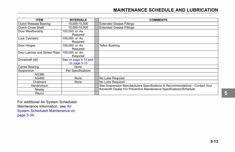
MAINTENANCE SCHEDULE AND LUBRICATION
ITEM INTERVALS COMMENTSClutch Release Bearing 10,000-15,000 Extended Grease FittingsClutch Cross Shaft 10,000-15,000 Extended Grease FittingsDoor Weatherstrip 100,000 or As
RequiredLock Cylinders 100,000 or As
RequiredDoor Hinges 100,000 or As
RequiredTeflon Bushing
Door Latches and Striker Plate 100,000 or AsRequired
Driveshaft (all) See on page 5-14 andon page 5-15
Center Bearing NoneSuspension Per Specifications
AG380AG400 None No Lube RequiredChalmers None No Lube Required
HendricksonNewayReyco
See Suspension Manufacturers Specifications & Recommendations - Contact YourKenworth Dealer For Preventive Maintenance Specifications/Schedule
For additional Air System ScheduledMaintenance information, see AirSystem Scheduled Maintenance onpage 5-34.
5-13
5
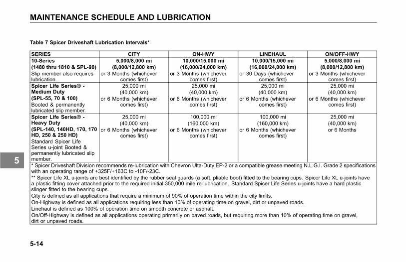
MAINTENANCE SCHEDULE AND LUBRICATION
Table 7 Spicer Driveshaft Lubrication Intervals*
SERIES CITY ON-HWY LINEHAUL ON/OFF-HWY10-Series(1480 thru 1810 & SPL-90)Slip member also requireslubrication.
5,000/8,000 mi(8,000/12,800 km)
or 3 Months (whichevercomes first)
10,000/15,000 mi(16,000/24,000 km)
or 3 Months (whichevercomes first)
10,000/15,000 mi(16,000/24,000 km)
or 30 Days (whichevercomes first)
5,000/8,000 mi(8,000/12,800 km)
or 3 Months (whichevercomes first)
Spicer Life Series® -Medium Duty(SPL-55, 70 & 100)Booted & permanentlylubricated slip member.
25,000 mi(40,000 km)
or 6 Months (whichevercomes first)
25,000 mi(40,000 km)
or 6 Months (whichevercomes first)
25,000 mi(40,000 km)
or 6 Months (whichevercomes first)
25,000 mi(40,000 km)
or 6 Months (whichevercomes first)
Spicer Life Series® -Heavy Duty(SPL-140, 140HD, 170, 170HD, 250 & 250 HD)Standard Spicer LifeSeries u-joint Booted &permanently lubricated slipmember.
25,000 mi(40,000 km)
or 6 Months (whichevercomes first)
100,000 mi(160,000 km)
or 6 Months (whichevercomes first)
100,000 mi(160,000 km)
or 6 Months (whichevercomes first)
25,000 mi(40,000 km)or 6 Months
* Spicer Driveshaft Division recommends re-lubrication with Chevron Ulta-Duty EP-2 or a compatible grease meeting N.L.G.I. Grade 2 specificationswith an operating range of +325F/+163C to -10F/-23C.** Spicer Life XL u-joints are best identified by the rubber seal guards (a soft, pliable boot) fitted to the bearing cups. Spicer Life XL u-joints havea plastic fitting cover attached prior to the required initial 350,000 mile re-lubrication. Standard Spicer Life Series u-joints have a hard plasticslinger fitted to the bearing cups.City is defined as all applications that require a minimum of 90% of operation time within the city limits.On-Highway is defined as all applications requiring less than 10% of operating time on gravel, dirt or unpaved roads.Linehaul is defined as 100% of operation time on smooth concrete or asphalt.On/Off-Highway is defined as all applications operating primarily on paved roads, but requiring more than 10% of operating time on gravel,dirt or unpaved roads.
5-14
5
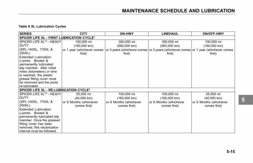
MAINTENANCE SCHEDULE AND LUBRICATION
Table 8 XL Lubrication Cycles
SERIES CITY ON-HWY LINEHAUL ON/OFF-HWYSPICER LIFE XL - FIRST LUBRICATION CYCLE*SPICER LIFE XL** - HEAVYDUTY(SPL-140XL, 170XL &250XL)Extended Lubricationu-joints. Booted &permanently lubricatedslip member. After initialmiles (kilometers) or timeis reached, the plasticgrease fitting cover mustbe removed and the jointsre-lubricated.
100,000 mi(160,000 km)
or 1 year (whichever comesfirst)
350,000 mi(560,000 km)
or 3 years (whichever comesfirst)
350,000 mi(560,000 km)
or 3 years (whichever comesfirst)
100,000 mi(160,000 km)
or 1 year (whichever comesfirst)
SPICER LIFE XL - RE-LUBRICATION CYCLE*SPICER LIFE XL** - HEAVYDUTY(SPL-140XL, 170XL &250XL)Extended Lubricationu-joints. Booted &permanently lubricated slipmember. Once the greasedfitting cover has beenremoved, this relubricationinterval must be followed.
25,000 mi(40,000 km)
or 6 Months (whichevercomes first)
100,000 mi(160,000 km)
or 6 Months (whichevercomes first)
100,000 mi(160,000 km)
or 6 Months (whichevercomes first)
25,000 mi(40,000 km)
or 6 Months (whichevercomes first)
5-15
5
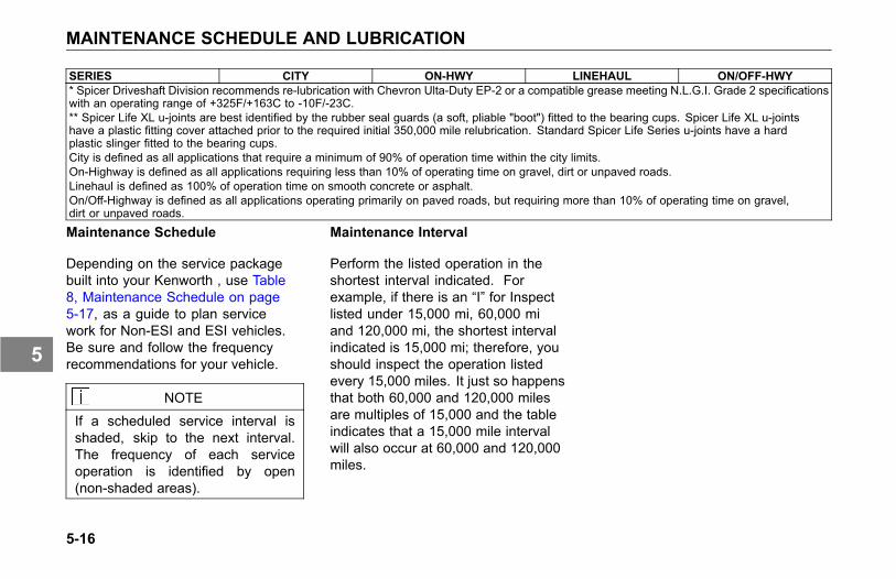
MAINTENANCE SCHEDULE AND LUBRICATION
SERIES CITY ON-HWY LINEHAUL ON/OFF-HWY* Spicer Driveshaft Division recommends re-lubrication with Chevron Ulta-Duty EP-2 or a compatible grease meeting N.L.G.I. Grade 2 specificationswith an operating range of +325F/+163C to -10F/-23C.** Spicer Life XL u-joints are best identified by the rubber seal guards (a soft, pliable "boot") fitted to the bearing cups. Spicer Life XL u-jointshave a plastic fitting cover attached prior to the required initial 350,000 mile relubrication. Standard Spicer Life Series u-joints have a hardplastic slinger fitted to the bearing cups.City is defined as all applications that require a minimum of 90% of operation time within the city limits.On-Highway is defined as all applications requiring less than 10% of operating time on gravel, dirt or unpaved roads.Linehaul is defined as 100% of operation time on smooth concrete or asphalt.On/Off-Highway is defined as all applications operating primarily on paved roads, but requiring more than 10% of operating time on gravel,dirt or unpaved roads.
Maintenance Schedule
Depending on the service packagebuilt into your Kenworth , use Table8, Maintenance Schedule on page5-17, as a guide to plan servicework for Non-ESI and ESI vehicles.Be sure and follow the frequencyrecommendations for your vehicle.
NOTE
If a scheduled service interval isshaded, skip to the next interval.The frequency of each serviceoperation is identified by open(non-shaded areas).
Maintenance Interval
Perform the listed operation in theshortest interval indicated. Forexample, if there is an “I” for Inspectlisted under 15,000 mi, 60,000 miand 120,000 mi, the shortest intervalindicated is 15,000 mi; therefore, youshould inspect the operation listedevery 15,000 miles. It just so happensthat both 60,000 and 120,000 milesare multiples of 15,000 and the tableindicates that a 15,000 mile intervalwill also occur at 60,000 and 120,000miles.
5-16
5

MAINTENANCE SCHEDULE AND LUBRICATION
TABLE KEY
A Part Of Federal Annual Inspection Every 120,000 Miles (192,000 km)I InspectR ReplaceG2 Synthetic Lube Required - 500,000 Drain
Table 9 Maintenance Schedule
INTERVALS COMMENTSOPERATION \ FREQUENCY 7,500 mi
(12,000km)
15,000 mi(24,000
km)
60,000 mi(96,000 km)
120,000 mi(193,000km)
AnnuallyINITIAL DRIVE-IN A B C D
Clutch Brake Operation I I IClutch Pedal Free Travel _____ inches I I IGlass for Cracks or Chips I I I ADoor Window OperationInterior Lights Replace As RequiredInterior Appearance:/Condition: Check For Tears, Stains, Wear
Seats I I I IFloor Mats I I I I
Door Panels I I I IHeadliner I I I I
Dash I I I ICovers I I I I
Wiper Operation I I I AWiper Blade Condition I I I A
5-17
5

MAINTENANCE SCHEDULE AND LUBRICATION
INTERVALS COMMENTSOPERATION \ FREQUENCY 7,500 mi
(12,000km)
15,000 mi(24,000
km)
60,000 mi(96,000 km)
120,000 mi(193,000km)
AnnuallyHorns (Electric and Air) I I I AMirrors I I I A
SAFETY EQUIPMENT A B C DDrain Water from Air Tanks I I I I DailyAir Tank Check Valve I I I AEmergency Operation of Spring Brakes I I I AAir Press. Build-up time: _______ min. I AGoverned Air Pressure: _______ psi I AAir Press. Drop-Brakes not Applied: ___ I AAir Press. Drop-Brakes Applied: ___ I AFire Extinguisher Charge Replace or Recharge Per Extinguisher
Manufacturer RecommendationsFlare Kit/Reflectors A
CIRCLE INSPECTION A B C DPhysical Damage:
Exterior Sheet Metal I I I IGrille and Radiator I I I I
Trailer Light Cord and Connectors I I I AAir Lines and Gladhands I I I A
Pintle - Hook/Eye Condition I I I A5th Wheel Mounting and Condition I I I A
Headlights - High and Low Beams I I I ARoad Lights I I I AMarker Lights I I I ATurn Signals I I I A
5-18
5
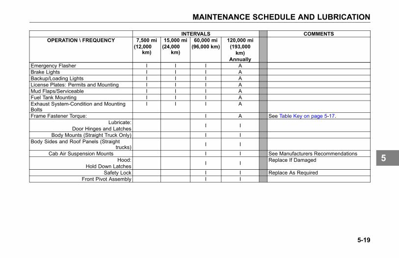
MAINTENANCE SCHEDULE AND LUBRICATION
INTERVALS COMMENTSOPERATION \ FREQUENCY 7,500 mi
(12,000km)
15,000 mi(24,000
km)
60,000 mi(96,000 km)
120,000 mi(193,000km)
AnnuallyEmergency Flasher I I I ABrake Lights I I I ABackup/Loading Lights I I I ALicense Plates: Permits and Mounting I I I AMud Flaps/Serviceable I I I AFuel Tank Mounting I I I AExhaust System-Condition and MountingBolts
I I I A
Frame Fastener Torque: I A See Table Key on page 5-17.Lubricate:
Door Hinges and Latches I I
Body Mounts (Straight Truck Only) I IBody Sides and Roof Panels (Straight
trucks) I I
Cab Air Suspension Mounts I I See Manufacturers RecommendationsHood:
Hold Down Latches I I Replace If Damaged
Safety Lock I I Replace As RequiredFront Pivot Assembly I I
5-19
5
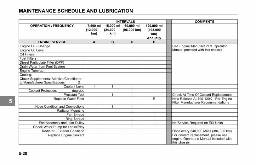
MAINTENANCE SCHEDULE AND LUBRICATION
INTERVALS COMMENTSOPERATION \ FREQUENCY 7,500 mi
(12,000km)
15,000 mi(24,000
km)
60,000 mi(96,000 km)
120,000 mi(193,000km)
AnnuallyENGINE SERVICE A B C D
Engine Oil - ChangeEngine Oil LevelOil FiltersFuel FiltersDiesel Particulate Filter (DPF)Drain Water from Fuel SystemEngine Tune-upCooling:Check Supplemental Additive/Conditionerto Manufacturer Specifications_______%
See Engine Manufacturers OperatorManual provided with this chassis
Coolant Level I I I ICoolant Protection: _______ degrees I I
Pressure Test I I I Check At Time Of Coolant ReplacementReplace Water Filter R New Release At 100-120K - Per Engine
Filter Manufacturer RecommendationsHose Condition and Connections I I I
Radiator Mounting I IFan Shroud I IRing Shroud I I
Fan Assembly and Idler Pulley I I No Service Required on ESI UnitsCheck Water Pump for Leaks/Play I I
Radiator - Exterior Condition Once every 240,000 Miles (384,000 km)Replace Engine Coolant For coolant replacement, please see
engine Operator’s Manual included withthis chassis
5-20
5
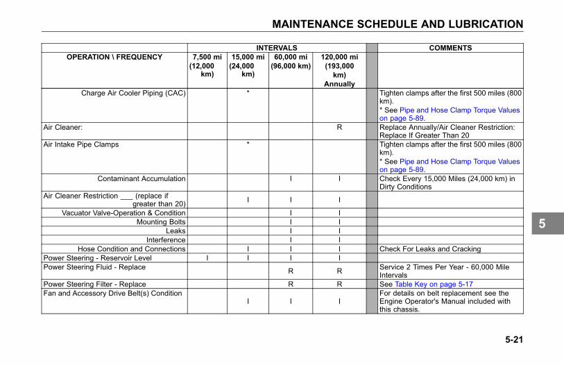
MAINTENANCE SCHEDULE AND LUBRICATION
INTERVALS COMMENTSOPERATION \ FREQUENCY 7,500 mi
(12,000km)
15,000 mi(24,000
km)
60,000 mi(96,000 km)
120,000 mi(193,000km)
AnnuallyCharge Air Cooler Piping (CAC) * Tighten clamps after the first 500 miles (800
km).* See Pipe and Hose Clamp Torque Valueson page 5-89.
Air Cleaner: R Replace Annually/Air Cleaner Restriction:Replace If Greater Than 20
Air Intake Pipe Clamps * Tighten clamps after the first 500 miles (800km).* See Pipe and Hose Clamp Torque Valueson page 5-89.
Contaminant Accumulation I I Check Every 15,000 Miles (24,000 km) inDirty Conditions
Air Cleaner Restriction ___ (replace ifgreater than 20) I I I
Vacuator Valve-Operation & Condition I IMounting Bolts I I
Leaks I IInterference I I
Hose Condition and Connections I I I Check For Leaks and CrackingPower Steering - Reservoir Level I I I IPower Steering Fluid - Replace R R Service 2 Times Per Year - 60,000 Mile
IntervalsPower Steering Filter - Replace R R See Table Key on page 5-17Fan and Accessory Drive Belt(s) Condition
I I IFor details on belt replacement see theEngine Operator's Manual included withthis chassis.
5-21
5
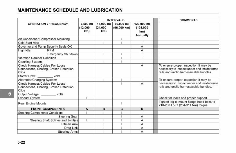
MAINTENANCE SCHEDULE AND LUBRICATION
INTERVALS COMMENTSOPERATION \ FREQUENCY 7,500 mi
(12,000km)
15,000 mi(24,000
km)
60,000 mi(96,000 km)
120,000 mi(193,000km)
AnnuallyAir Conditioner Compressor Mounting I ICold Start Aids I I IGovernor and Pump Security Seals OK AHigh Idle: ________ RPM A
Emergency Shutdown I I IVibration Damper Condition I I
I I ICranking System:Check Harness/Cables For LooseConnections, Chafing, Broken RetentionClipsStarter Draw: _________ volts
A To ensure proper inspection it may benecessary to inspect under and inside framerails and unclip harness/cable bundles.
I I IAlternator/Charging System:Check Harness/Cables For LooseConnections, Chafing, Broken RetentionClipsOutput Voltage: _________ volts
I ATo ensure proper inspection it may benecessary to inspect under and inside framerails and unclip harness/cable bundles.
Exhaust System I Check for leaks and proper support.
Rear Engine Mounts I Tighten leg to mount flange head bolts to210-230 Lb-Ft (284-311 Nm) torque
FRONT COMPONENTS A B C DSteering Components Condition: I I I I
Steering Gear I ASteering Shaft Splines and Joint(s) I I I A
Pitman Arm I I ADrag Link I I A
Steering Arms I I A
5-22
5
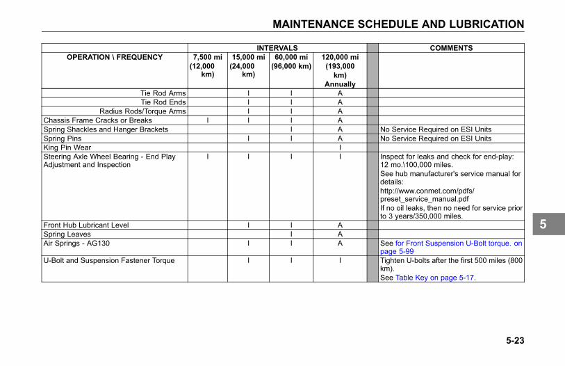
MAINTENANCE SCHEDULE AND LUBRICATION
INTERVALS COMMENTSOPERATION \ FREQUENCY 7,500 mi
(12,000km)
15,000 mi(24,000
km)
60,000 mi(96,000 km)
120,000 mi(193,000km)
AnnuallyTie Rod Arms I I ATie Rod Ends I I A
Radius Rods/Torque Arms I I AChassis Frame Cracks or Breaks I I I ASpring Shackles and Hanger Brackets I A No Service Required on ESI UnitsSpring Pins I I A No Service Required on ESI UnitsKing Pin Wear ISteering Axle Wheel Bearing - End PlayAdjustment and Inspection
I I I I Inspect for leaks and check for end-play:12 mo.\100,000 miles.See hub manufacturer's service manual fordetails:http://www.conmet.com/pdfs/preset_service_manual.pdfIf no oil leaks, then no need for service priorto 3 years/350,000 miles.
Front Hub Lubricant Level I I ASpring Leaves I AAir Springs - AG130 I I A See for Front Suspension U-Bolt torque. on
page 5-99U-Bolt and Suspension Fastener Torque I I I Tighten U-bolts after the first 500 miles (800
km).See Table Key on page 5-17.
5-23
5
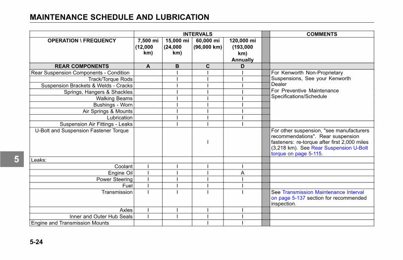
MAINTENANCE SCHEDULE AND LUBRICATION
INTERVALS COMMENTSOPERATION \ FREQUENCY 7,500 mi
(12,000km)
15,000 mi(24,000
km)
60,000 mi(96,000 km)
120,000 mi(193,000km)
AnnuallyREAR COMPONENTS A B C D
Rear Suspension Components - Condition I I ITrack/Torque Rods I I I
Suspension Brackets & Welds - Cracks I I ISprings, Hangers & Shackles I I I
Walking Beams I I IBushings - Worn I I I
Air Springs & Mounts I I ILubrication I I I
For Kenworth Non-ProprietarySuspensions, See your KenworthDealerFor Preventive MaintenanceSpecifications/Schedule
Suspension Air Fittings - Leaks I I IU-Bolt and Suspension Fastener Torque
I
For other suspension, "see manufacturersrecommendations". Rear suspensionfasteners: re-torque after first 2,000 miles(3,218 km). See Rear Suspension U-Bolttorque on page 5-115.
Leaks:Coolant I I I I
Engine Oil I I I APower Steering I I I I
Fuel I I I ITransmission I I I I See Transmission Maintenance Interval
on page 5-137 section for recommendedinspection.
Axles I I I IInner and Outer Hub Seals I I I I
Engine and Transmission Mounts I I
5-24
5

MAINTENANCE SCHEDULE AND LUBRICATION
INTERVALS COMMENTSOPERATION \ FREQUENCY 7,500 mi
(12,000km)
15,000 mi(24,000
km)
60,000 mi(96,000 km)
120,000 mi(193,000km)
AnnuallyDrivelines - U-joints and Slip Yokes I IRear Axle Lubricant Level I I IRear Axle Lubricant Flush & Refill Non-ESI - 250,000 Miles/ESI - 500,000
Miles.See Table Key on page 5-17.
Rear Axle Breathers - Clear I I I IVehicle Protection Valve Breakaway Test I I I IBrake Chamber Mounting Bolt Torque I I ABrake Hoses for Cracks and Chafing I I I AAdjust Brakes I I AFront & Rear Brake Camshaft TubeLubrication I A Synthetic Grease Required - Special Fitting
Clutch Pedal Shaft I I No Service Required on ESI UnitsClutch Linkage I ISuspension Air Fittings I I IClutch Release Bearing A Required Extended FittingsDriveline Center Bearing I I No Service Required on ESI UnitsAutomatic Slack Adjusters I I I I Standard (non-LMS)Automatic Slack Adjusters I With LMS, Synthetic Lube Required -
Special FittingI I ABrakes: Lining Remaining (replace as
required)RF ______RRF ______RRR ______
5-25
5
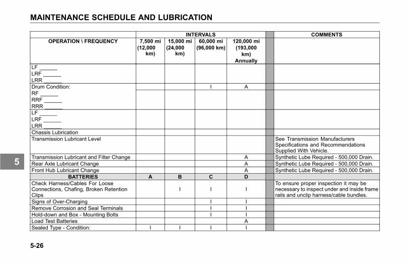
MAINTENANCE SCHEDULE AND LUBRICATION
INTERVALS COMMENTSOPERATION \ FREQUENCY 7,500 mi
(12,000km)
15,000 mi(24,000
km)
60,000 mi(96,000 km)
120,000 mi(193,000km)
AnnuallyLF ______LRF ______LRR ______
I ADrum Condition:RF ______RRF ______RRR ______LF ______LRF ______LRR ______Chassis LubricationTransmission Lubricant Level See Transmission Manufacturers
Specifications and RecommendationsSupplied With Vehicle.
Transmission Lubricant and Filter Change A Synthetic Lube Required - 500,000 Drain.Rear Axle Lubricant Change A Synthetic Lube Required - 500,000 Drain.Front Hub Lubricant Change A Synthetic Lube Required - 500,000 Drain.
BATTERIES A B C DCheck Harness/Cables For LooseConnections, Chafing, Broken RetentionClips
I I ITo ensure proper inspection it may benecessary to inspect under and inside framerails and unclip harness/cable bundles.
Signs of Over-Charging I IRemove Corrosion and Seal Terminals I IHold-down and Box - Mounting Bolts I ILoad Test Batteries ASealed Type - Condition: I I I I
5-26
5
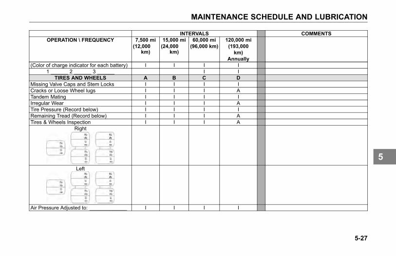
MAINTENANCE SCHEDULE AND LUBRICATION
INTERVALS COMMENTSOPERATION \ FREQUENCY 7,500 mi
(12,000km)
15,000 mi(24,000
km)
60,000 mi(96,000 km)
120,000 mi(193,000km)
Annually(Color of charge indicator for each battery) I I I I
1 ______ 2 ______ 3 ______ I ITIRES AND WHEELS A B C D
Missing Valve Caps and Stem Locks I I I ICracks or Loose Wheel lugs I I I ATandem Mating I I I IIrregular Wear I I I ATire Pressure (Record below) I I I IRemaining Tread (Record below) I I I ATires & Wheels Inspection I I I A
Right
Left
Air Pressure Adjusted to: _____________ I I I I
5-27
5
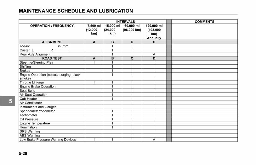
MAINTENANCE SCHEDULE AND LUBRICATION
INTERVALS COMMENTSOPERATION \ FREQUENCY 7,500 mi
(12,000km)
15,000 mi(24,000
km)
60,000 mi(96,000 km)
120,000 mi(193,000km)
AnnuallyALIGNMENT A B C D
Toe-in: ______________ in (mm) I ICaster: L ________ R ________ I IRear Axle Alignment I A
ROAD TEST A B C DSteering/Steering Play I I I IShifting I I IBrakes I I IEngine Operation (noises, surging, blacksmoke)
I I I
Throttle Linkage I I I IEngine Brake Operation I I ISeat Belts I I IAir Seat Operation I I ICab Heater I I IAir Conditioner I IInstruments and Gauges:Speedometer/odometer I I ITachometer I I IOil Pressure I I IEngine Temperature I I IIllumination I I ISRS Warning I IABS Warning I ILow Brake Pressure Warning Devices I I I A
5-28
5
MAINTENANCE SCHEDULE AND LUBRICATION
Lubrication Specifications
You will find a complete EngineLubrication Service Guide in the EngineOperation and Maintenance Manual.There, the engine manufacturerexplains more fully all the maintenanceoperations you and a qualified servicemechanic will need. And pleaseremember: one key to keeping yourKenworth running at top economyand in prolonging its life is properlubrication servicing. Neglecting thisessential aspect of vehicle care cancost time and money in the long run.
Below you will find basic informationneeded to perform routine vehiclelubrication. Of course you will wantto schedule service more frequentlyif operating in severe conditionssuch as extreme heat or cold, withvery heavy loads, off-road, etc. Forany special service requirements,consult your service manuals and yourlubricant supplier. The componentmanufacturer's specification andrequirements take precedence overother specifications.
CAUTION
Handle lubricants carefully. Vehiclelubricants (oil and grease) can bepoisonous and cause sickness.They can also damage the paint onthe vehicle.
CAUTION
Do not mix different types oflubricants. Mixing lubricants (oiland grease) of different brandsor types could damage vehiclecomponents; therefore, drain (orremove) old lubricants from the unitbefore refilling it.
5-29
5

MAINTENANCE SCHEDULE AND LUBRICATION
Oil Reservoirs
For oil reservoirs with side filler plugs(transmissions, axles, steering gearboxes, transfer cases, etc.), the oilmust be level with the filler opening.
NOTEUse care when checking the oil levelwith a finger. Just because you canreach the oil level with a finger, doesnot mean the oil level is correct.
NOTEFactory oil level may be above thislevel because it is measured as avolume and not as a specific oillevel. This is acceptable to theaxle manufacturers; however, refillshould be per the Proper Oil Levelas shown in the figure below.
1 Improper Oil Level2 Proper Oil Level
Lubrication Chart
The following lubrication specifications(Table 10) are for an ambient operatingtemperature range of -15° to 100°F (-26° to 38° C). For extremetemperature operations, consult thecomponent manufacturers manuals.
5-30
5
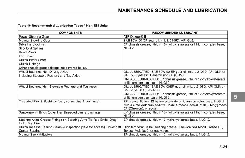
MAINTENANCE SCHEDULE AND LUBRICATION
Table 10 Recommended Lubrication Types * Non-ESI Units
COMPONENTS RECOMMENDED LUBRICANTPower Steering Gear ATF Dexron® IIIManual Steering Gear SAE 80W-90 CP gear oil, miL-L-2105D, API GL5.Driveline U-JointsSlip-Joint SplinesHood PivotsFan DriveClutch Pedal ShaftClutch LinkageOther chassis grease fittings not covered below.
EP chassis grease, lithium 12-hydroxystearate or lithium complex base,NLGI 2.
OIL LUBRICATED: SAE 80W-90 EP gear oil, miL-L-2105D, API GL5; orSAE 50 Synthetic Transmission Oil (CD50).
Wheel Bearings-Non Driving AxlesIncluding Steerable Pushers and Tag Axles
GREASE LUBRICATED: EP chassis grease, lithium 12-hydroxystearateor lithium complex base, NLGI 2.OIL LUBRICATED: SAE 80W-90EP gear oil, miL-L-2105D, API GL5; orSAE 75W-90 Synthetic Oil
Wheel Bearings-Non Steerable Pushers and Tag Axles
GREASE LUBRICATED: EP chassis grease, lithium 12-hydroxystearateor lithium complex base, NLGI 2.
Threaded Pins & Bushings (e.g., spring pins & bushings) EP grease, lithium 12-hydroxystearate or lithium complex base, NLGI 2,with 3% molybdenum additive: Mobil Grease Special (Mobil), MolygreaseEP (Chevron), or equal.
Suspension Fittings (other than threaded pins & bushings) EP chassis grease, lithium 12-hydroxystearate or lithium complex base,NLGI 2.
Steering Axle: Grease Fittings on Steering Arm; Tie Rod Ends; DragLink; King Pins
EP chassis grease, lithium 12-hydroxystearate base, NLGI 2.
Clutch Release Bearing (remove inspection plate for access); DriveshaftCenter Bearing
High temperature ball bearing grease. Chevron SRI Mobil Grease HP,Texaco Multifax 2, or equivalent.
Manual Slack Adjusters EP chassis grease, lithium 12-hydroxystearate base, NLGI 2.
5-31
5

MAINTENANCE SCHEDULE AND LUBRICATION
COMPONENTS RECOMMENDED LUBRICANTAutomatic Slack Adjusters; Wedge Brake Components; Disc BrakeCaliper
High temperature EP grease; Texaco Thermotex EP-1, Shell DarinaEP-1, Mobilith AW-1, Meritor 0-616A, or equivalent.
Cam Brake Camshaft Splines; Disc Brake Shaft Splines and Slide PinRetainers; Brake Clevis Pins
Anti-seize type grease, Meritor specification 0-637.
Brake Camshaft Bushings EP Chassis grease, lithium 12-hydroxystearate base, NLGI 2.
CAUTIONDo not contaminate brake linings with grease.
Steering Shaft Grease Fittings EP chassis grease, lithium 12-hydroxystearate base, NLGI 2.Brake Treadle Hinge and Roller Engine oilLock Cylinders Lock lubricant.Door Hinges Not required - Teflon bushingsDoor Latches & Striker Plates Polyethylene grease stick.Door Weatherstrip Silicone lubricant.Axle U-Bolt Threads Chevron Zinc Lubrication anti-seize compound is recommended; or use
EP chassis grease, lithium 12-hydroxystearate or lithium complex base,NLGI 2
Hub-piloted Aluminum Wheels Coat the wheel pilot or hub pads with Freylube #3 lubricant (light colored)or Chevron Zinc lube. Do not get lubricant on the face of the wheel orthe hub.
Other Items Use manufacturers manuals.
5-32
5
AIR SYSTEM MAINTENANCE
AIR SYSTEMMAINTENANCE
Introduction
WARNING
Prior to the removal of any airsystem component, always blockand hold the vehicle by a securemeans other than the vehicle'sown brakes. Depleting air systempressure may cause vehicle toroll unexpectedly resulting in anaccident. Keep hands away fromchamber push rods and slackadjusters, they may apply as systempressure drops. Failure to complymay result in personal injury, death,equipment or property damage.
• Never connect or disconnecta hose or line containing airpressure. It may whip as airescapes. Never remove acomponent or pipe plug unless
you are certain all systempressure has been depleted.
• Never exceed recommendedair pressure and always wearsafety glasses when workingwith air pressure. Never lookinto air jets or direct them atanyone.
• Never attempt to disassemble acomponent until you have readand understood recommendedprocedures. Some componentscontain powerful springs andinjury or death can result if notproperly disassembled. Useonly proper tools and observeall precautions pertaining to theuse of those tools.
WARNING
Do not release the parking brake orattempt to move the vehicle until airpressure in both circuits is at least100 psi (690 kPa), the level requiredfor normal brake operation. Failureto comply may result in personalinjury, death, equipment or propertydamage.
• Do not use the trailer hand brakecontrol to hold vehicle whileparked. This control utilizes airpressure for brake application.Because acceptable air leakagelevels cause all truck airsystems to gradually losepressure, vehicle rollawaycould occur, resulting in anaccident, injuries or death.
• Always apply the vehicle andtrailer parking brakes when thevehicle is unattended.
5-33
5
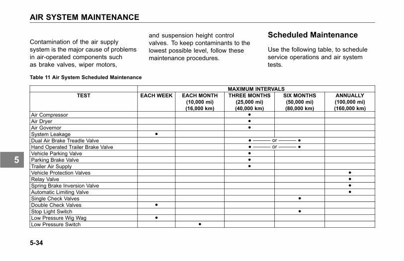
AIR SYSTEM MAINTENANCE
Contamination of the air supplysystem is the major cause of problemsin air-operated components suchas brake valves, wiper motors,
and suspension height controlvalves. To keep contaminants to thelowest possible level, follow thesemaintenance procedures.
Scheduled Maintenance
Use the following table, to scheduleservice operations and air systemtests.
Table 11 Air System Scheduled Maintenance
MAXIMUM INTERVALSTEST EACH WEEK EACH MONTH
(10,000 mi)(16,000 km)
THREE MONTHS(25,000 mi)(40,000 km)
SIX MONTHS(50,000 mi)(80,000 km)
ANNUALLY(100,000 mi)(160,000 km)
Air Compressor ●Air Dryer ●Air Governor ●System Leakage ●Dual Air Brake Treadle Valve ● –––––– or –––––– ●Hand Operated Trailer Brake Valve ● –––––– or –––––– ●Vehicle Parking Valve ●Parking Brake Valve ●Trailer Air Supply ●Vehicle Protection Valves ●Relay Valve ●Spring Brake Inversion Valve ●Automatic Limiting Valve ●Single Check Valves ●Double Check Valves ●Stop Light Switch ●Low Pressure Wig Wag ●Low Pressure Switch ●
5-34
5
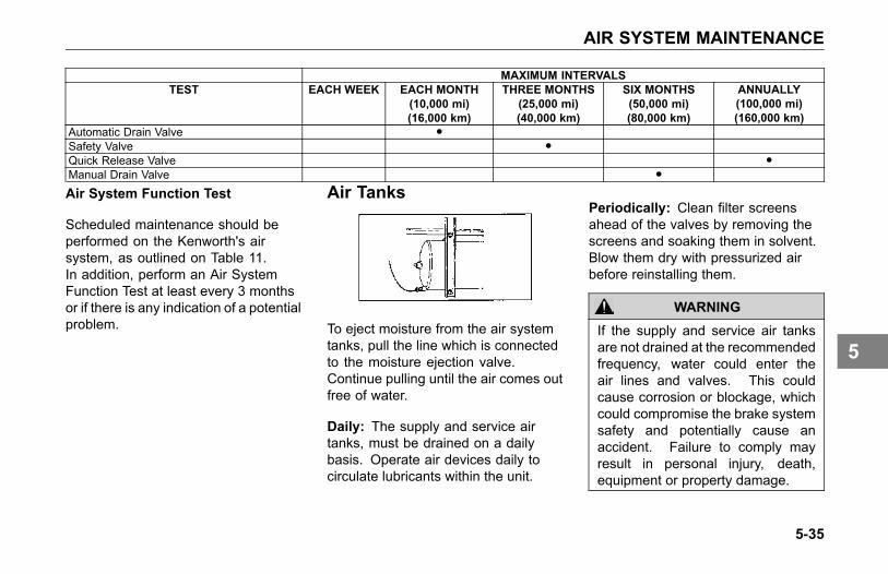
AIR SYSTEM MAINTENANCE
MAXIMUM INTERVALSTEST EACH WEEK EACH MONTH
(10,000 mi)(16,000 km)
THREE MONTHS(25,000 mi)(40,000 km)
SIX MONTHS(50,000 mi)(80,000 km)
ANNUALLY(100,000 mi)(160,000 km)
Automatic Drain Valve ●Safety Valve ●Quick Release Valve ●Manual Drain Valve ●
Air System Function Test
Scheduled maintenance should beperformed on the Kenworth's airsystem, as outlined on Table 11.In addition, perform an Air SystemFunction Test at least every 3 monthsor if there is any indication of a potentialproblem.
Air Tanks
To eject moisture from the air systemtanks, pull the line which is connectedto the moisture ejection valve.Continue pulling until the air comes outfree of water.
Daily: The supply and service airtanks, must be drained on a dailybasis. Operate air devices daily tocirculate lubricants within the unit.
Periodically: Clean filter screensahead of the valves by removing thescreens and soaking them in solvent.Blow them dry with pressurized airbefore reinstalling them.
WARNING
If the supply and service air tanksare not drained at the recommendedfrequency, water could enter theair lines and valves. This couldcause corrosion or blockage, whichcould compromise the brake systemsafety and potentially cause anaccident. Failure to comply mayresult in personal injury, death,equipment or property damage.
5-35
5
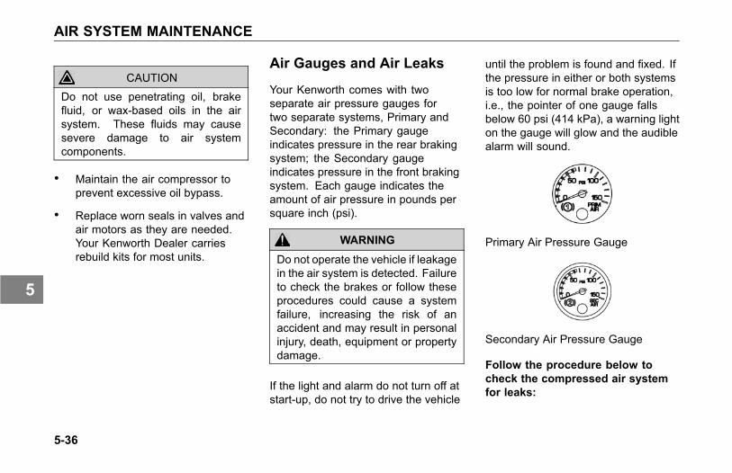
AIR SYSTEM MAINTENANCE
CAUTIONDo not use penetrating oil, brakefluid, or wax-based oils in the airsystem. These fluids may causesevere damage to air systemcomponents.
• Maintain the air compressor toprevent excessive oil bypass.
• Replace worn seals in valves andair motors as they are needed.Your Kenworth Dealer carriesrebuild kits for most units.
Air Gauges and Air Leaks
Your Kenworth comes with twoseparate air pressure gauges fortwo separate systems, Primary andSecondary: the Primary gaugeindicates pressure in the rear brakingsystem; the Secondary gaugeindicates pressure in the front brakingsystem. Each gauge indicates theamount of air pressure in pounds persquare inch (psi).
WARNING
Do not operate the vehicle if leakagein the air system is detected. Failureto check the brakes or follow theseprocedures could cause a systemfailure, increasing the risk of anaccident and may result in personalinjury, death, equipment or propertydamage.
If the light and alarm do not turn off atstart-up, do not try to drive the vehicle
until the problem is found and fixed. Ifthe pressure in either or both systemsis too low for normal brake operation,i.e., the pointer of one gauge fallsbelow 60 psi (414 kPa), a warning lighton the gauge will glow and the audiblealarm will sound.
Primary Air Pressure Gauge
Secondary Air Pressure Gauge
Follow the procedure below tocheck the compressed air systemfor leaks:
5-36
5
AIR SYSTEM MAINTENANCE
1. Periodically, or after maintenanceor replacement of air systemcomponents:
2. Build up air pressure in the systemto the governor cutout point or until120 psi (827 kPa) is reached.
3. Stop the engine and release theservice brakes.
4. Without applying the brake pedal,observe the rate of air pressuredrop. This rate should not exceed2.0 psi (14 kPa) per minute.
5. Start the engine and build up theair pressure again.
6. Stop the engine, and apply thebrakes fully. Apply the brake pedaland hold it down for five minutes.The pressure drop should notexceed 3.0 psi (21 kPa) perminute.
7. If you detect excessive leakage(air pressure loss greater than
3.0 psi after five minutes of brakeapplication), a leakage test shouldbe made at the air line connectionsand at all air brake control units.These tests should determinewhere air is escaping.
Air CompressorOperation
All compressors, regardless of makeor model, run continuously while theengine is running. System pressureis controlled by the governor. Thegovernor acts in conjunction withthe unloading mechanism in thecompressor cylinder block to startand stop compression of air. Thecompressor is unloaded when thesystem pressure reaches 120 psi (827kPa) and compression is reestablishedwhen system pressure falls to 100 psi(690 kPa).
5-37
5
AIR SYSTEM MAINTENANCE
Preventive Maintenance
The following service checks areprovided for your information onlyand should be performed by acertified mechanic. Contact yourKenworth Dealer or the enginemanufacturer's Maintenance Manualfor further information on servicing aircompressors.
After completing any repairs to the airsystem, always test for air leaks, andcheck the brakes for safe operationbefore putting the vehicle in service.
According to Table 11, Air SystemScheduled Maintenance on page 5-34:
• Inspect compressor air filterelement, if so equipped, andreplace element if clogged. Checkcompressor mounting and drivefor alignment and belt tension.Adjust if necessary.
• Remove compressor dischargevalve cap nuts and check forpresence of excessive carbon. Ifexcessive carbon is found, cleanor replace the compressor cylinderhead. Also, check compressordischarge line for carbon, andclean or replace the discharge lineif necessary.
• Disassemble compressor andthoroughly clean and inspectall parts. Repair or replaceall worn or damaged parts, orreplace compressor with a factoryexchange unit.
CAUTIONWhen draining the engine coolingsystem is required, to preventdamage from freezing, thecompressor must also be drained atthe cylinder head and block. Enginedamage could occur if the coolingsystem is not periodically drainedand maintained. See CoolingSystem on page 5-60 for furtherinformation.
5-38
5
AIR SYSTEM MAINTENANCE
Air Dryer
The function of the air dryer is to collectand remove air system contaminants insolid, liquid and vapor form before theyenter the brake system. It providesclean, dry air to the components ofthe brake system, which increasesthe life of the system and reducesmaintenance costs.
NOTEBecause no two vehicles operateunder identical conditions,maintenance and maintenanceintervals will vary. Experience is avaluable guide in determining thebest maintenance interval for anyone particular operation.
Every 900 operating hours or 25,000miles or every three (3) months checkfor moisture in the air brake systemby opening air tanks, drain cocks, or
valves and checking for presence ofwater.
NOTE
A small amount of oil in the systemmay be normal and should not,in itself, be considered a reasonto replace the desiccant cartridge.Oil stained desiccant can functionadequately.
A tablespoon of water found in theair tank would point to the need for adesiccant cartridge change. However,the following conditions can alsocause water accumulation and shouldbe considered before replacing thedesiccant cartridge.
• Air usage is exceptionally highand not normal for a highwayvehicle. This may be due toaccessory air demands or someunusual air requirement thatdoes not allow the compressorto load and unload (compressing
and non-compressing cycle) in anormal fashion or it may be due toexcessive leaks in the air system.
• In areas where more than a 30°F (17° C) range of temperatureoccurs in one day, small amountsof water can accumulate inthe air brake system due tocondensation. Under theseconditions, the presence of smallamounts of moisture is normaland should not be considered asan indication that the dryer is notperforming properly.
• An outside air source has beenused to charge the air system.This air did not pass through thedrying bed.
5-39
5
AIR SYSTEM MAINTENANCE
Overhaul
Maintenance intervals typical foron-highway operation would be 2 - 3years, 350,000 miles or 10,800 hours.
Maintenance intervals typical for highduty cycle usage such as transit bus,refuse hauler, dump truck, cementmixers and off-highway operationwould be 1 year, 100,000 miles or3,600 hours.
NOTE
Review the warranty policy beforeperforming any maintenanceprocedures. An extended warrantymay be voided if unauthorizedmaintenance is performed duringthis period.
Bendix AD-IS Series Air Dryer
Your Kenworth vehicle may beequipped with a Bendix AD-IS seriesair dryer. Any air dryer replacementshould be made with an identicalcomponent.
WARNING
If a different air dryer brand or modelis installed on the vehicle otherthan what was originally installed,it could cause the air system tonot perform correctly unless thefull air system design is reviewedand modifications made to complywith Federal Motor Vehicle SafetyStandards (FMVSS) 121 - Air BrakeSystems. Failure to abide by thiswarning and maintain complianceto FMVSS 121 could cause lossof vehicle control and may lead toserious personal injury or death.
NOTE
The AD-IS Series air dryer hasincorporated into its design variouscomponents that have typically beeninstalled separately on the vehicle.
See below for components/areasaffected.
• Pressure protection valves
• Safety valve
• Governor and plumbing
• Plumbing of the front and rearservice air tanks
• Plumbing to accessory systems
5-40
5
AIR SYSTEM MAINTENANCE
These components are required tomeet the Federal Motor Vehicle SafetyStandards (FMVSS 121 - Air BrakeSystems). As the Warning abovestates, any other type of air dryerinstalled in the place of an AD-IS Serieswill require changes, modifications,and/or additions to your vehicle’sair system to maintain compliancewith FMVSS 121. Kenworth stronglyrecommends that if the air dryeris changed from an AD-IS series,you consult your nearest authorizedKenworth dealer.
Air Intake System
Engine heat, vibration, and agecombine to loosen air intakeconnections and cause cracks inthe tubing and elbows. Leaks in theintake system allow abrasive dust toenter the engine and quickly causeexpensive damage. During your dailywalk-around inspection, carefullycheck all tubing, elbows, clampssupports and fasteners for conditionand tightness.
• Check the Charge-Air-Cooler forair leaks annually. The air leakscan be caused by cracked tubesor header. For service see yourauthorized Kenworth Dealer.
CAUTIONDo not use air intake pipes andconnections as a step or to pullyourself up. This could loosen theconnections and open the system tounfiltered air which could damagethe engine.
5-41
5
AIR SYSTEM MAINTENANCE
Turbocharger
When servicing the air intake andexhaust systems on a turbochargedengine, check the items listed below.
WARNING
Do not operate engine withturbocharger intake pipingdisconnected. A suction is createdwhen the engine is running. Thissuction could draw your hand oranything else near it into the impellerfan. You could be injured. Alwayskeep the intake piping connectedwhen you will be running the engine.
Lubricating System: Check the oillines, housing, and connections. Lookfor leaks, damage, or deterioration.Leaks could mean you have damagedoil lines or oil seals.
Manifold: With the engine operating,check for leaking manifold or flangegaskets.
High Frequency Vibration: Vibrationmay indicate turbo rotor imbalance.Have your Kenworth Dealer investigatethis immediately. If you detect anydeficiencies, take the vehicle toan authorized Kenworth Dealer forservicing. Delay could lead to severeand expensive damage to your vehicle.
Air Cleaners and FilterReplacement
The following service information isbasic to all air cleaner makes andmodels. Service the filter elementswhen the (option) locks in the extremeHigh position. Have the elementserviced at an authorized KenworthDealer. Paper elements require careand proper handling, because they arecritical to engine service life.
Service the air cleaner periodically.If the vehicle operates in areas withheavy dust, maintenance should bemore frequent.
5-42
5
BRAKE SYSTEM MAINTENANCE
BRAKE SYSTEMMAINTENANCE
Introduction
To operate your vehicle safely, youneed some understanding of its brakesystems. Brake adjustment and brakebalance must be set carefully to allowequal stopping forces at all wheels.Tires are also a very important part ofthe whole system. How fast you canstop depends on how much frictionthere is between the road and yourtires.
All of the following areas areinterrelated and must conform tooriginal specifications:
• tire size
• cam radius
• wedge angle
• drum radius
• brake linings
• brake chambers
• slack adjusters
NOTE
The air brake system of thisvehicle was configured for ONEof the following operations,TRACTOR or TRUCK, andcomplies with the respectiveportions of Federal Motor VehicleSafety Standards (FMVSS) 121.A tractor shall not be operatedor configured as a truck, norshall a truck be operated orconfigured as a tractor withoutsignificant modifications to theair brake system in order to retaincompliance with FMVSS 121.Contact your Kenworth dealer forinstructions.
Once a brake system is set tospecifications, changing any one ofits components or any combination ofcomponents may cause the system notto work as well. All parts have to worktogether to perform as they should.
Because your brake system is airoperated, see Air System Maintenanceon page 5-33 for more information onchecking your brakes.
Any replacement components inthe brake system should be thesame or better than the originalcomponents. Any changes from theoriginal specifications can affect theperformance of the entire system.
5-43
5
BRAKE SYSTEM MAINTENANCE
WARNING
Do not use any replacement part inthe brake system unless it conformsexactly to original specifications.A nonconforming part in yourvehicle's brake system could causea malfunction resulting in an injuryaccident. Sizes and types areso related to one another that aseemingly unimportant change inone may result in a change in howwell the brakes work for you on theroad. If parts do not work togetherproperly, you could lose control ofyour vehicle, which could cause aserious accident. Failure to complymay result in personal injury, death,equipment or property damage.
WARNING
Do not work on the brake systemwithout the parking brake set andwheels chocked securely. If thevehicle is not secured to preventuncontrolled vehicle movement, itcould roll and may result in personalinjury, death, equipment or propertydamage.
CAUTION
Use wood blocks (4 in. X 4 in.or larger) against the front and rearsurfaces of the tires. Be sure thevehicle cannot move.
Lubrication
Cam-actuated brake componentssuch as anchor pins and brakecamshafts are subjected to hightemperatures, and must be lubricatedwith non-melting, water resistant brakegrease meeting R-S Specification0-616 (NLGI-Grade 1).
• Lubricate according to Table6, Recommended LubricationIntervals on page 5-11.
WARNING
Do not apply too much lubricantto brake components, lubricatesparingly. Excessive amountsof lubricant could contaminatebrake linings, which could reducebrake effectiveness and cause anaccident. Failure to comply mayresult in personal injury, death,equipment or property damage.
5-44
5

BRAKE SYSTEM MAINTENANCE
Brake and Slack AdjusterLubrication
According to the interval, pressurelubricate the slack adjuster and brakecamshaft (bracket/tube). Two greasefittings are provided for both the slackadjuster and camshaft bracket/tube.
• Use standard chassis lubricant(meeting No. 1 grade hightemperature, water proofspecifications).
• Do not use moly-disulfide loadedgrease or oil (they may shorten theservice life of the slack adjuster).
• Do not use pressure-releasegrease fittings when lubricatingthe slack adjuster.
Checks and Adjustments
All vehicle Operator's should check thebrakes regularly. Always adjust thebrakes when they are cool.
• Park the vehicle on a level surfaceand block the wheels beforeattempting any brake checks oradjustments.
Brake Linings
WARNING
Do not use brake linings witha thickness below the specifiedminimum. Such linings will havelining rivets exposed that candamage the brake drum and reducebrake efficiency, which could causean accident or system failure.Failure to comply may result inpersonal injury, death, equipment orproperty damage.
• Brake linings should be inspectedby a qualified mechanic at anauthorized Kenworth Dealer forwear. See Table 9, MaintenanceSchedule on page 5-17. In severeservice applications inspect thelinings more frequently.
5-45
5
BRAKE SYSTEM MAINTENANCE
NOTEDepending on your vehicles servicepackage (ESI or Non-ESI), brakeservice requirements will vary.
Automatic Slack Adjusters
Your Kenworth is equipped withautomatic brake (slack) adjusters.
WARNING
Do not work on the brake systemwithout the parking brake set and/orthe wheels chocked securely. If thevehicle is not secured to preventuncontrolled vehicle movement, itcould roll and may result in personalinjury, death, equipment or propertydamage.
CAUTION
Use wood blocks (4 in. X 4 in.or larger) against the front and rearsurfaces of the tires. Be sure thevehicle cannot move.
Periodically, brake adjustmentshould be checked using thefollowing procedure:
1. Check brakes when thetemperature of the servicebrake linings are cool and thesystem air pressure at 100 psi(690 kPa) minimum.
NOTE
Chock the tires before proceeding.
2. Release the parking brakes toallow the slack adjusters to retract.
3. Measure the retracted pushrodlength from the face of the brakechamber to the center of thepushrod pin.
4. Apply 80 to 90 psi brake applicationand measure the same distance.
5. The difference is the pushrodtravel distance (applied stroke).
5-46
5
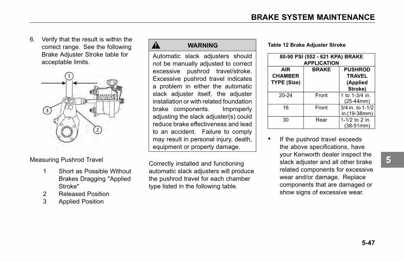
BRAKE SYSTEM MAINTENANCE
6. Verify that the result is within thecorrect range. See the followingBrake Adjuster Stroke table foracceptable limits.
Measuring Pushrod Travel
1 Short as Possible WithoutBrakes Dragging "AppliedStroke"
2 Released Position3 Applied Position
WARNING
Automatic slack adjusters shouldnot be manually adjusted to correctexcessive pushrod travel/stroke.Excessive pushrod travel indicatesa problem in either the automaticslack adjuster itself, the adjusterinstallation or with related foundationbrake components. Improperlyadjusting the slack adjuster(s) couldreduce brake effectiveness and leadto an accident. Failure to complymay result in personal injury, death,equipment or property damage.
Correctly installed and functioningautomatic slack adjusters will producethe pushrod travel for each chambertype listed in the following table.
Table 12 Brake Adjuster Stroke
80-90 PSI (552 - 621 KPA) BRAKEAPPLICATION
AIRCHAMBERTYPE (Size)
BRAKE PUSHRODTRAVEL(AppliedStroke)
20-24 Front 1 to 1-3/4 in.(25-44mm)
16 Front 3/4 in. to 1-1/2in.(19-38mm)
30 Rear 1-1/2 to 2 in.(38-51mm)
• If the pushrod travel exceedsthe above specifications, haveyour Kenworth dealer inspect theslack adjuster and all other brakerelated components for excessivewear and/or damage. Replacecomponents that are damaged orshow signs of excessive wear.
5-47
5

BRAKE SYSTEM MAINTENANCE
NOTEThe automatic brake adjusteralone does not ensure properbrake operation. Inspect all brakecomponents. All brake componentswork together and must be checkedperiodically to ensure the brakesystem works properly.
Anti-Lock Braking System(ABS)
Below are some general notes on yourKenworth anti-lock braking system. Allservice work should be performed bya qualified technician at an authorizedKenworth Dealer. The foundationbrake system must be in properworking order to ensure the best ABSperformance.
CAUTION
Before welding anywhere on thevehicle, detach the ABS ElectronicControl Unit (ECU) connector andall other electronic control units.Failure to comply may result inequipment damage.
CAUTION
Never detach the ECU connectorwith the ignition turned on. Failureto comply may result in equipmentdamage.
NOTE
Check ABS wiring harnessesand piping periodically for chafingor other problems. No regularmaintenance is required on the ABScomponents.
NOTEDuring wheel balancing, dynotesting, or any time the ignition is onwith part of the ABS disconnected,a failure code will be recorded.Consult with your authorizedKenworth Dealer for information onclearing the failure code.
5-48
5
BRAKE SYSTEM MAINTENANCE
If, due to operating conditions, a brakeapplication causes either wheel on thesame axle to begin skidding, wheelspeed sensors immediately signal theanti-lock controller in the modulatorassembly. The controller respondsinstantly by signaling the solenoids inthe modulator which activate the airvalves, reducing application pressureas needed to prevent the wheels fromlocking up. If this over-riding correctionis effective, application pressure isallowed to build up to the original input.
Any malfunction of the anti-locksystem on one or more axles willcause the system to fail-safe, andthe panel-mounted amber warninglight will come on, indicating both amalfunction, and automatic shut-downof the system. If the air system is intact(indicated by the pressure gauges),the service brakes will continue tofunction normally, but without benefitof the anti-lock feature.
NOTE
If one wheel on any driven axlecontinues to slip or spin forapproximately 4 seconds, this willcause the anti-lock controller for thataxle to go into the fail-safe mode,and the warning light will give ashutdown signal.
• In this case, the anti-lock systemcan be turned back on, and thewarning light extinguished, byturning the key switch OFF andON, after the vehicle has beenbrought to a full stop. When thekey switch is turned back on, thewarning light will illuminate andremain on for 3 to 5 seconds. Thisis a built-in function test of thewarning light.
WARNING
Do not attempt to recycle theanti-lock system by turning the keyswitch OFF and ON until the vehiclehas been brought to a full stop andthe parking brakes set. Failure to doso could adversely affect steeringand braking control, and may resultin loss of vehicle control and anaccident. Failure to comply mayresult in personal injury, death,equipment or property damage.
5-49
5

BRAKE SYSTEM MAINTENANCE
WARNING
Do not operate the vehicle in theevent of a malfunction in any aircircuit. Such a malfunction mayprevent the brake system fromoperating properly, and could resultin an injury accident. The vehicleshould not be operated until thesystem is repaired and both brakingcircuits, including all pneumaticand mechanical components, areworking properly. Failure to complymay result in personal injury, death,equipment or property damage.
5-50
5

CAB MAINTENANCE
CAB MAINTENANCE
Exterior MaintenancePainted Surfaces
Wash painted surfaces frequently toremove grime and caustic depositswhich may stain the finish. SeeCleaning, Protecting, and WeatherStripping on page 5-52.
Chrome and Aluminum Surfaces
To prevent rust, keep chromed partsclean and protected with wax at alltimes, especially in winter conditionswhere the roads are salted.
• If necessary, use a commercialchrome cleaner to remove lightrust.
• Chrome surfaces are bestcleaned with fresh water. Wipedry to preserve their luster. Acommercial chrome cleaner willremove light rust. After cleaning,wax flat surfaces and apply a thincoat of rust preventive lubricantaround bolts or other fasteners.
• Clean aluminum wheels andbumpers with warm water. Tarremover will get rid of heavydeposits of road grime. To preventspotting, wipe aluminum surfacesdry after washing.
• Under corrosive conditions, suchas driving on salted roads, cleanaluminum parts with steam or highpressure water from a hose. Amild soap solution will help. Rinsethoroughly.
5-51
5
CAB MAINTENANCE
Tail Pipe Surface Cleaning
To maintain your quality finish, washwith a soft cloth, mild soap and wateror glass cleaner. A non-abrasivechrome polish can be used sparinglyon hard to clean areas. Do Not cleanyour high heat chrome using scouringpads, abrasive chrome polish, highlyacidic chemical cleaners or any otherabrasive cleaners.
CAUTIONUsing improper cleaning agents canharm your high heat chrome andinvalidate your warranty.
Stainless Steel
Even high quality stainless steel partscan rust under prolonged exposureto salt water, especially when thesalt-laden moisture is held againstthe metal surface by road grime. Itis, therefore, important to frequentlyclean salty moisture and grime fromstainless steel surfaces.
• If surface rust is encountered,wash the surface and use acommercial polishing compoundto clean off the rust, followed bya coating of wax (do not applywax to hot parts, such as exhaustpipes).
• Never use steel wool whencleaning stainless steel becauseminute particles of the steel woolcan embed in the surface of thestainless steel and cause ruststaining.
Cleaning, Protecting andWeather Stripping
Frequent washings of the vehicleare required to remove grime andcontaminants that can stain andoxidize paint and accelerate corrosionof plated and polished metal surfaces.
Waxing offers added protection againststaining and oxidation. But to allowenough time for your truck's finish tocure, wait about 30 days after the dateof manufacture before waxing. Do notapply wax in the hot sun and do notfriction burn the paint with a buffingmachine.
Occasionally spray weather-strippingon doors and windows with siliconecompound to help preserve resiliency.This is especially useful in freezingweather to prevent doors and windowsfrom sticking shut with ice.
5-52
5
CAB MAINTENANCE
Vehicle Cleaning
Precautions
WARNING
Handle cleaning agents carefully.Cleaning agents may be poisonous.Keep them out of the reach ofchildren.
• Observe all caution labels.
• Always read directions on thecontainer before using anyproduct.
• Do not use any solution that candamage the body paint.
• Most chemical cleaners areconcentrates which requiredilution.
• Only use spot removing fluids inwell ventilated areas.
• Do not use gasoline, kerosene,naphtha, nail polish remover
or other volatile cleaning fluids.They may be toxic, flammable orhazardous in other ways.
• Do not clean the underside ofchassis, fenders wheel covers,etc. without protecting your handsand arms. You may cut yourselfon sharp-edged metal parts.
• Moisture, ice, and road salton brakes may affect brakingefficiency. Test the brakescarefully after each vehicle wash.
• Any vehicle is subjected todeterioration from industrialfumes, ice, snow, corrosive roadsalt, etc., to name just a fewcauses. A well-cared-for vehiclecan look like new many yearslater. Regular and correct carewill contribute to maintaining thebeauty and the value of yourvehicle.
Your Kenworth Dealer has a number ofvehicle-care products and can adviseyou on which ones to use for cleaningthe exterior and interior of your vehicle.
CAUTIONDo not aim the water jet directly atdoor locks or latch. Tape the keyholes to prevent water from seepinginto the lock cylinders. Water in lockcylinders should be removed withcompressed air. To prevent locksfrom freezing in the winter, squirtglycerin or lock deicer into the lockcylinders.
5-53
5
CAB MAINTENANCE
Washing the Exterior
1. Begin by spraying water over thedry surface to remove all loose dirtbefore applying the car wash andwax solution.Do not wash the vehicle in directsunshine.Do not spray water directly into thecab and sleeper vents.
2. Using soapy water, wash thevehicle with a clean soft cloth ora soft brush made for automotivecleaning.Use cool or warm water and amild, household type soap. Strongindustrial detergents and cleaningagents are not recommended.Do not use stiff brushes, papertowels, steel wool, or abrasivecleaning compounds becausethey will scratch painted, plated,and polished metal surfaces.
3. Rinse surfaces frequently whilewashing to flush away dirt that
might scratch the finishes duringthe washing operation.
4. Wipe everything dry with achamois to avoid water spots.To prevent water spotting, dry offthe cosmetic surfaces with a cleancloth or chamois.
5. Remove road tar with anautomotive type tar remover ormineral spirits.
6. After cleaning and drying, apply aquality automotive wax.
° Do not apply wax in the hotsun.
° Never dust off dry surfaceswith a cloth because it willscratch the finishes.
NOTE
To allow enough time for your truck'sfinish to cure, wait at least thirty daysafter the date of manufacture beforewaxing.
5-54
5
CAB MAINTENANCE
Cleaning the Chassis
• Hose dirt and grime from theentire chassis. Then, if an oilleak develops, you will be able todetect it easier.
• Corrosive materials used for iceand snow removal and dust controlcan collect on the underbody. Ifthese materials are not removed,accelerated corrosion (rust) canoccur on underbody parts such asfuel lines, frames, floor pan, andexhaust system, even though theyhave been provided with corrosionprotection.
At least every spring, flush thesematerials from the under body withplain water. Be sure to clean anyarea where mud and other debris cancollect. Sediment packed in closedareas of the frame should be loosenedbefore being flushed. If desired, yourKenworth Dealer can do this servicefor you.
Cleaning Interior Vinyl andUpholstery
• Wipe vinyl upholstery and liningwith a good commercial upholsterycleaner. Do not use acetone orlacquer thinner.
• Clean fabric upholstery withupholstery shampoo speciallyformulated for this purpose. Followinstructions on the container.
Safety Restraint System -Inspection
The seat belt system, includingwebbing, buckles, latches, andmounting hardware, endures heavyuse in heavy-duty vehicles, much morethan seat belt systems in passengercars. All users should be aware of thefactors contributing to this heavy useand reduced belt life.
WARNING
Failure to properly inspect andmaintain restraint systems canlead to injury or loss of life.Without periodic inspectionand maintenance to detectunsafe conditions, seat restraintcomponents can wear out or notprotect you in an accident.
5-55
5

CAB MAINTENANCE
Factors contributing to reducedseat belt life:
• High mileage heavy trucks, oftenaccumulate mileage in excess of500,000 total miles (800,000 km)during the vehicle lifetime. Thisis much greater than a typicalpassenger car, which frequentlywill not exceed 125,000 total miles(200,000 km).
• Seat and cab movement intrucks, there is almost constantmovement of the belt due to ridecharacteristics and seat design.The constant movement of the beltinside the restraint hardware andthe potential for the belt to comein contact with the cab and othervehicle parts, contributes to thewear of the entire system.
• Environmental conditions, such asdirt and ultraviolet rays from thesun, will reduce the life of the seatbelt system.
Due to these factors, the three-pointsafety belt system installed in yourvehicle requires thorough inspectionevery 20,000 miles (32,000 km). Ifthe vehicle is exposed to severeenvironmental or working conditions,more frequent inspections may benecessary.
Any seat belt system that shows cuts,fraying, extreme or unusual wear,significant discoloration due to UV(ultraviolet) exposure, abrasion to theseat belt webbing, or damage to thebuckle, latch plate, retractor hardwareor any other obvious problem shouldbe replaced immediately, regardlessof mileage.
WARNING
It is important to remember thatany time a vehicle is involved in anaccident, the entire seat belt systemmust be replaced. Unexposeddamage caused by the stress of anaccident could prevent the systemfrom functioning properly the nexttime it is needed. Failure to complymay result in personal injury ordeath.
5-56
5

CAB MAINTENANCE
Inspection Guidelines
Follow these guidelines wheninspecting for cuts, fraying, extremeor unusual wear of the webbing,and damage to the buckle, retractor,hardware, or other factors. Damage tothese areas indicates that belt systemreplacement is necessary.
WARNING
Replace the entire belt system(retractor and buckle side) ifreplacement of any one part isnecessary. Unexposed damageto one or more components couldprevent the system from functioningproperly the next time it is needed.Failure to comply may result inpersonal injury or death.
1. Check the web wear in the system.The webbing must be closelyexamined to determine if it iscoming into contact with any sharpor rough surfaces on the seat or
other parts of the cab interior.These areas are typical placeswhere the web will experiencecutting or abrasion. Cuts, fraying,or excessive wear would indicatethe need for replacement of theseat belt system.
2. The pillar web guide (D-loop) isthe area where almost constantmovement of the seat beltwebbing occurs because ofrelative movement between theseat and cab.
3. Check the Comfort Clip for cracksor possible damage and check forproper operation.
4. Check buckle and latch for properoperation and to determine iflatch plate is worn, deformed, ordamaged.
5. Inspect the retractor web storagedevice, which is mounted on thefloor of the vehicle, for damage.The retractor is the heart of the
occupant restraint system and canoften be damaged if abused, evenunintentionally. Check operationto ensure that it is not locked upand that it spools out and retractswebbing properly.
6. If tethers are used, be sure theyare properly attached to theseat and, if adjustable, that theyare adjusted in accordance withinstallation instructions. Tethersmust also be inspected for webwear and proper tightness ofmounting hardware.
7. Mounting hardware should beevaluated for corrosion, and fortightness of bolts and nuts.
8. Check web in areas exposed toultraviolet rays from the sun.
5-57
5
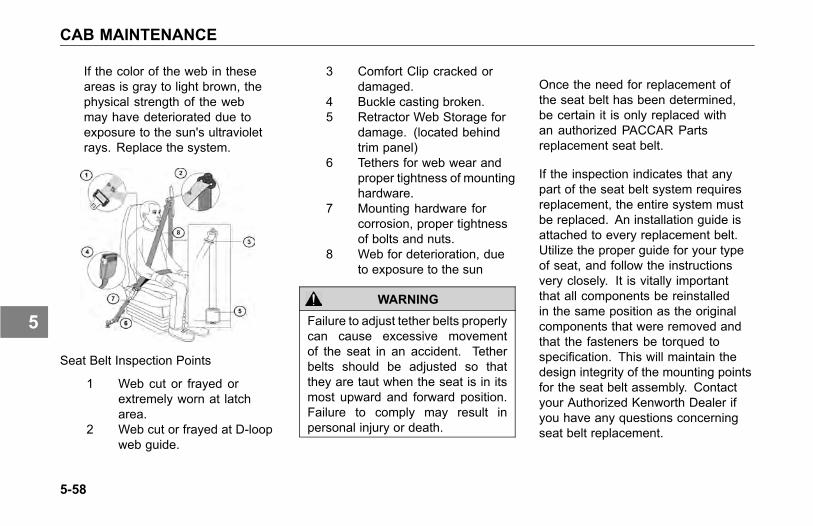
CAB MAINTENANCE
If the color of the web in theseareas is gray to light brown, thephysical strength of the webmay have deteriorated due toexposure to the sun's ultravioletrays. Replace the system.
Seat Belt Inspection Points
1 Web cut or frayed orextremely worn at latcharea.
2 Web cut or frayed at D-loopweb guide.
3 Comfort Clip cracked ordamaged.
4 Buckle casting broken.5 Retractor Web Storage for
damage. (located behindtrim panel)
6 Tethers for web wear andproper tightness of mountinghardware.
7 Mounting hardware forcorrosion, proper tightnessof bolts and nuts.
8 Web for deterioration, dueto exposure to the sun
WARNING
Failure to adjust tether belts properlycan cause excessive movementof the seat in an accident. Tetherbelts should be adjusted so thatthey are taut when the seat is in itsmost upward and forward position.Failure to comply may result inpersonal injury or death.
Once the need for replacement ofthe seat belt has been determined,be certain it is only replaced withan authorized PACCAR Partsreplacement seat belt.
If the inspection indicates that anypart of the seat belt system requiresreplacement, the entire system mustbe replaced. An installation guide isattached to every replacement belt.Utilize the proper guide for your typeof seat, and follow the instructionsvery closely. It is vitally importantthat all components be reinstalledin the same position as the originalcomponents that were removed andthat the fasteners be torqued tospecification. This will maintain thedesign integrity of the mounting pointsfor the seat belt assembly. Contactyour Authorized Kenworth Dealer ifyou have any questions concerningseat belt replacement.
5-58
5

CAB MAINTENANCE
Windshield Wiper/Washer
The windshield wiper system ismaintenance free. Check wiperblades annually or every 60,000 miles(96,000 km). Anco wiper bladesare recommended. See WindshieldWipers/Washer on page 3-102, formore information.
Washer Reservoir
CAUTION
Do not use antifreeze or enginecoolant in the windshield washerreservoir, damage to seals and othercomponents will result.
Daily: Check reservoir water level,located in the engine compartment. Ifnecessary, refill to the proper level.
5-59
5

COOLING SYSTEM MAINTENANCE
COOLING SYSTEMMAINTENANCE
WARNING
Do not remove the radiator cap ona hot engine. It can cause scaldingcoolant to spray out and you couldbe burned. If the engine has beenoperated within the last 30 minutes,be very careful in removing theradiator cap. Failure to complymay result in personal injury, death,equipment or property damage.
WARNING
Do not work on the fan with theengine running. The engine fan canengage at any time without warning.Anyone near the fan when it turnson could be injured. Before turningon the ignition be sure that no oneis near the fan. Failure to complymay result in personal injury, death,equipment or property damage.
Kenworth Trucks are standard withAir-to-Air cooling systems. Thesecooling systems incorporate a radiatorto cool engine jacket water, a ChargeAir Cooler to cool turbo-charged engineintake air, and a refrigerant condenserto provide cab air conditioning.
Topping Up
Check the coolant level after eachtrip when the engine has cooled. Thecoolant level should be visible withinthe sight gauge (glass level indicator)on the surge tank. Add coolant asnecessary (see Adding Coolant onpage 5-62).
With the engine cold, top up withpremixed coolant. Add the coolantthrough the pressure cap neck on thesurge tank. The surge tank is locatedon the firewall, right side.
With the engine cold, the coolant levelshould be at the full cold coolant level.Use caution not to overfill the systemwith coolant. An overfilled coolingsystem will cause loss of cool antthrough the radiator cap as the coolantexpands during heating.
5-60
5

COOLING SYSTEM MAINTENANCE
Replacement or makeup coolantshould have the same antifreezeconcentration and corrosion inhibitorcontent as the original coolant in thecooling system. Never add 100%antifreeze to the cooling system.Always dilute anti-freeze to thecorrect concentration based on freezeprotection prior to adding it to thecooling system. Adding or using 100%antifreeze in a cooling system mayresult in cooling system plugging andoverheating problems.
NOTE
If frequent topping up is necessaryand there are not visible signs ofcoolant leaks when the engine iscold, check for leaks with the engineoperating at normal operatingtemperature.
WARNING
Do not remove the radiator cap ona hot engine. It can cause scaldingcoolant to spray out and you couldbe burned. If the engine has beenoperated within the last 30 minutes,be very careful in removing theradiator cap.
• Protect face, hands, and armsagainst escaping fluid andsteam by covering the cap witha large, thick rag.
• Carefully and slowly turn cap (onexpansion surge tank) one quarterof a turn to allow excess pressureto escape before completelyremoving cap. If you see anysteam or coolant escaping, donot even try to remove it until theradiator cools down.
If you see nothing escaping, stillremove the cap very slowly andcarefully. Be ready to back off ifany steam or coolant begins toescape.
WARNING
Handle coolant and antifreezecarefully. Ethylene glycol antifreezeis poisonous. Store in original fluidcontainer only, and always keepout of reach of children. Failureto comply may result in personalinjury, death, equipment or propertydamage.
WARNING
Never remove the cap on the surgetank while the engine is still hot.Wait until the coolant temperatureis below 120º F (50º C). Scaldingsteam and fluid under pressure mayescape and cause personal injuries.
5-61
5
COOLING SYSTEM MAINTENANCE
WARNING
Do not work on the fan with theengine running. The engine fan canengage at any time without warning.Anyone near the fan when it turnson could be injured. Before turningon the ignition, be sure that no oneis near the fan.
Adding Coolant
A mixture of water and low silicateantifreeze should be used forcoolant. Water must be clean andfree of corrosive and scale-formingchemicals. Drinking water may not begood for your vehicle. New vehiclescome premixed with antifreeze andcorrosion inhibitor. Be sure differenttypes of coolant are not mixed. Staywith the same coolant until a completeReplacement is performed.
NOTEExcess coolant may result inoverflow, loss of antifreeze, andreduced corrosion protection. For acold engine, the proper coolant levelis 1 in. below the radiator cap seal.For normal operating temperatures,coolant should be even with theradiator cap seal.
Coolant Conditioner
A variety of test methods are availablefor measuring coolant conditionerlevels. Test strips provide convenientand consistent results with minimaltraining. Other test methods can beused when appropriate training isprovided. The actual test (i.e. teststrips, etc.) and coolant conditionermaintenance schedule should bedone in accordance with the actualcoolant conditioner manufacturerrecommendations.
The coolant conditioner should berecharged according to Table 6,Recommended Lubrication Intervalson page 5-11, unless otherwisespecified in the Engine ManufacturersMaintenance Manual.
5-62
5
COOLING SYSTEM MAINTENANCE
Additives
If you add supplemental coolantadditives to the radiator, maintain themat the recommended levels. Readthe label carefully. Too much additivecould harm your vehicle.
Approved additives help neutralizethe water's harmful effects on yourvehicle's cooling system. Ask yourdealer to recommend the best onesfor you.
• Do not add rust inhibitors,radiator sealants, or water pumplubricants containing soluble oil tothe coolant. These additives cancause the anti-corrosion chemicalsnot to work.
• If the cooling system in your truckhas a treated spin-on water filter,install the service filter on all B or Escheduled service intervals. SeeTable 9, Maintenance Scheduleon page 5-17.
For more detailedrecommendations check withyour Kenworth Dealer or check themanufacturer's Engine Operationand Maintenance Manual.
• Antifreeze solutions containinganti-leak additives will quicklyrestrict the water filter. If thishappens, the filter will not work.So stay away from anti-leakadditives.
CAUTION
Do not add inhibitor if the engine hasa Dry Charge Additive (DCA4) waterfilter cartridge containing corrosioninhibitor, engine damage from overconcentration of silicates may occur.
• The water filter cartridgecontaining DCA4 inhibitor mustbe periodically changed. Referto the Engine Operation andMaintenance Manual for details.
CAUTIONDo not mix inhibitor types. Impropermixing of coolant may damage theengine.
• For coolant conditioner rechargeintervals see the Engine Operationand Maintenance Manual.
5-63
5
COOLING SYSTEM MAINTENANCE
Change and Refilling
The coolant must be changedperiodically. When draining coolant,capture old coolant and dispose of itproperly.
Refilling
To refill the cooling system, followthe recommendations below:
1. Before refilling be sure the radiatorand engine block drains areclosed.
2. Move the heater control tomaximum heat position.
3. Remove the surge tank pressurecap.
4. Through the surge tank, fill thesystem with premixed coolant.Pour it in a steady flow until theradiator is full.
5. Start the engine and idle it at lowRPM.
6. Complete the filling as quicklyas possible. Idle the engineuntil it reaches normal operatingtemperature.
7. Fill the radiator as necessaryto raise the coolant level to theproper level.
8. Replace the surge tank pressurecap.
You may find the coolant level is notup to the correct level soon after youhave filled the radiator. This maybe because all the trapped air in thesystem has not yet been purged. Ittakes a little time for all the air to leavethe system after you fill the radiator.
For further details on coolant, coolantcapacities, water filters, and antifreezemixture see the Engine Operation andMaintenance Manual (supplied withthe vehicle).
5-64
5

COOLING SYSTEM MAINTENANCE
Radiator Cap
CAUTIONWhen replacing the radiator capalways use one with the correctrated pressure. Failure to do socould cause engine or coolingsystem damage.
All radiator caps are marked with therated pressure (psi) of the cap.
Engine (Block) Heater
Regularly inspect the engine blockheater wiring and connector fordamaged or frayed wires. Contactyour authorized Kenworth Dealer orthe manufacturer of the heater if youare in need of repairs or information.
WARNING
Do not use the heater if there areany signs of problems. Engine blockheaters can cause fires resulting inpersonal injury, death, equipmentor property damage if not properlymaintained and operated.
CAUTIONAlways unplug the block heaterbefore starting your engine.Damage to the cooling system couldoccur if not turned OFF (unplugged).
Use a solution of half ethylene glycolantifreeze and half water for bestheater performance. Do not usemore than 65 percent concentration ofantifreeze, as a shortened heater lifewill result.
After servicing the cooling system,operate the vehicle for a day or twobefore using the heater. Trappedair inside the engine needs time toescape.
5-65
5

ELECTRICAL MAINTENANCE
ELECTRICALMAINTENANCE
Electrical System
WARNING
Battery posts, terminals and relatedaccessories contain lead and leadcompounds, chemicals known to theState of California to cause cancerand reproductive harm. Wash handsafter handling.
CAUTION
Do not modify or improperly repairthe vehicles electrical system orpower distribution box. All electricalrepairs should be performed byan authorized Kenworth dealer.Improper repair or modifications willvoid your warranty and/or causeserious damage to your vehicle.
Fuses, Circuit Breakers, AndRelays
Fuses, circuit breakers, and relaysare located in the Power DistributionBox to the left of the steering columnbehind the clutch pedal. See PowerDistribution Box on page 5-68.Additional fuses for the alternator,engine electronics and trailer batterycharge circuit may be located in thePower Distribution Center (PDC) insidethe battery box and/ or on the engineside of the cab firewall. Power Distribution Center (shown
without fuse cover)
1. MEGA FUSE2. MIDI FUSE
5-66
5
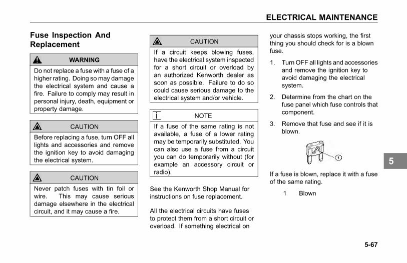
ELECTRICAL MAINTENANCE
Fuse Inspection AndReplacement
WARNING
Do not replace a fuse with a fuse of ahigher rating. Doing somay damagethe electrical system and cause afire. Failure to comply may result inpersonal injury, death, equipment orproperty damage.
CAUTION
Before replacing a fuse, turn OFF alllights and accessories and removethe ignition key to avoid damagingthe electrical system.
CAUTION
Never patch fuses with tin foil orwire. This may cause seriousdamage elsewhere in the electricalcircuit, and it may cause a fire.
CAUTION
If a circuit keeps blowing fuses,have the electrical system inspectedfor a short circuit or overload byan authorized Kenworth dealer assoon as possible. Failure to do socould cause serious damage to theelectrical system and/or vehicle.
NOTE
If a fuse of the same rating is notavailable, a fuse of a lower ratingmay be temporarily substituted. Youcan also use a fuse from a circuityou can do temporarily without (forexample an accessory circuit orradio).
See the Kenworth Shop Manual forinstructions on fuse replacement.
All the electrical circuits have fusesto protect them from a short circuit oroverload. If something electrical on
your chassis stops working, the firstthing you should check for is a blownfuse.
1. TurnOFF all lights and accessoriesand remove the ignition key toavoid damaging the electricalsystem.
2. Determine from the chart on thefuse panel which fuse controls thatcomponent.
3. Remove that fuse and see if it isblown.
If a fuse is blown, replace it with a fuseof the same rating.
1 Blown
5-67
5
ELECTRICAL MAINTENANCE
Adding Electrical Options
WARNING
Do not add a fuse with a ratinghigher than 30 amps. Followthe circuit protection size/typerecommended by the componentmanufacturer. Installing a fuseor circuit breaker greater thandesignated may damage theelectrical system which could lead toequipment damage and/or personalinjury.
CAUTION
Follow all manufacturers' circuitprotection recommendations forthe components and wires beingadded. Failure to comply may resultin equipment damage.
NOTE
If you are unfamiliar with properelectrical repair practices andprocedures, see your authorizedKenworth dealer for assistance.
NOTE
Easy addition of circuits is providedby plug-in connectors that have aground and a power wire.
For proper electrical systemperformance, refer to a wiringdiagram for your chassis before addingelectrical options.
WARNING
Never install a circuit breaker in acircuit that is designated as “fuse-only” circuit(s). Fuse-only circuitsare marked with an * on the reverseside of the Power Distribution Boxcover. Using a circuit breaker inthose fuse-only circuits may causethe circuit to overheat when a shortexists which could lead to equipmentdamage and/or personal injury.
5-68
5
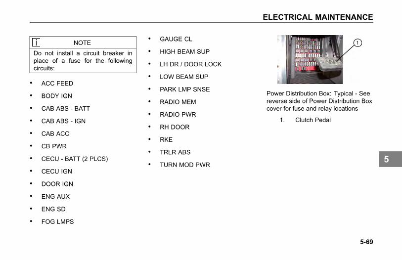
ELECTRICAL MAINTENANCE
NOTEDo not install a circuit breaker inplace of a fuse for the followingcircuits:
• ACC FEED
• BODY IGN
• CAB ABS - BATT
• CAB ABS - IGN
• CAB ACC
• CB PWR
• CECU - BATT (2 PLCS)
• CECU IGN
• DOOR IGN
• ENG AUX
• ENG SD
• FOG LMPS
• GAUGE CL
• HIGH BEAM SUP
• LH DR / DOOR LOCK
• LOW BEAM SUP
• PARK LMP SNSE
• RADIO MEM
• RADIO PWR
• RH DOOR
• RKE
• TRLR ABS
• TURN MOD PWR
Power Distribution Box: Typical - Seereverse side of Power Distribution Boxcover for fuse and relay locations
1. Clutch Pedal
5-69
5
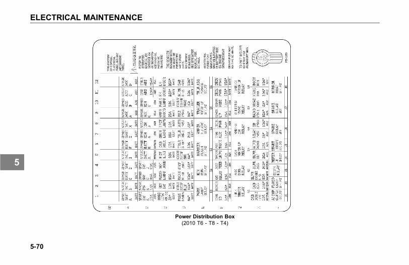
ELECTRICAL MAINTENANCE
Power Distribution Box(2010 T6 - T8 - T4)
5-70
5
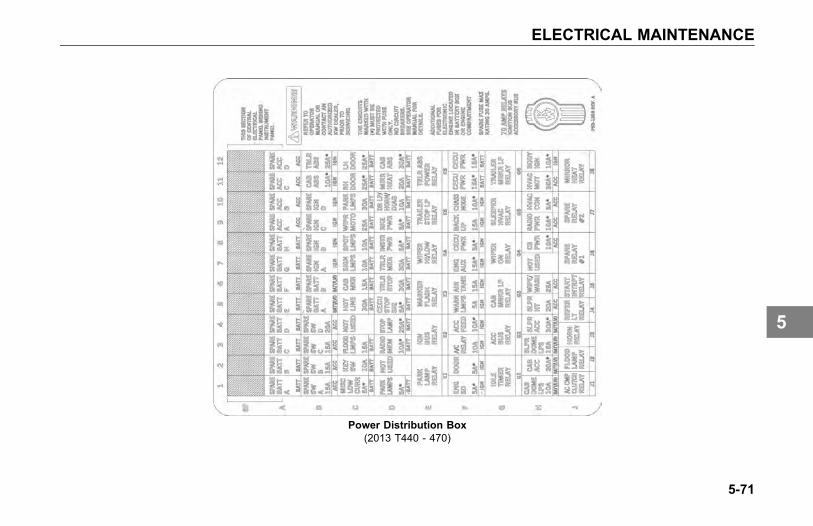
ELECTRICAL MAINTENANCE
Power Distribution Box(2013 T440 - 470)
5-71
5

ELECTRICAL MAINTENANCE
Chassis Load Center Fuse Box (Cummins)
5-72
5
ELECTRICAL MAINTENANCE
Batteries
Battery Access
The vehicle is originally equipped withthree or four batteries. Replacementbatteries must meet the followingspecifications: maintenance-free,group 31 size, threaded stud, 12V/ 650cold cranking ampere (CCA), and 160minutes of reserve capacity.
The battery compartment is located onthe left side of the vehicle, under thecab access steps.
1. Remove steps by removing 2 boltsfrom each step.
2. Remove 4 bolts and washers fromforward fairing.
3. Remove 2 bolts (A) from step strut.
4. Remove battery cover for access.
In-Cab Battery Box
Your vehicle may be equipped withOptima brand Absorbed Glass Mat(AGM) batteries located in the cabunder the passenger’s seat. The glassmat in AGM batteries is designed toabsorb the battery acid inside thebattery that can leak or spill out inconventional batteries. This designfeature allows Optima batteries to bepositioned in any orientation withoutrisk of leaking.
To access the batteries:
1. Remove 6 fasteners securing thepassenger side seat base to thebattery box assembly.
2. Remove the seat and seat baseas one unit to gain access to thebatteries.
WARNING
Replace only with Optima brandAGM (Group 31) batteries. Use ofother batteries could result in acidleaks causing personal injury in theevent of a vehicle accident. Failureto comply may result in personalinjury, death, equipment or propertydamage.
5-73
5
ELECTRICAL MAINTENANCE
WARNING
Battery cables and air/electricalharnesses are mounted to thebottom of the floor. Do not drillor screw into floor pan withoutfirst checking the location of thecables, harnesses or any othercomponent that might be damaged.Damaging any component couldresult in electrical shock which couldcause personal injury and/or lossof a critical truck system. Failureto comply may result in personalinjury, death, equipment or propertydamage.
WARNING
Electrical damage or batteryexplosion can occur whenimproperly charging batteries.Refer to the operation and servicemanual for appropriate charginginstructions. Failure to comply mayresult in personal injury, death,equipment or property damage.
WARNING
Batteries release gases that areflammable. Batteries are equippedwith vent tubes and flash arrestorswhich vent battery gases out ofthe cab. Ensure all vent tubes,flash arrestors and grommets areproperly installed and ensure theyare clear and functioning properly.Failure to reinstall or keep the venttubes and grommets clear or ensurethe flash arrestor(s) are functioningproperly could result in personalinjury or equipment damage. Failureto comply may result in personalinjury, death, equipment or propertydamage.
CAUTIONDo not store other items in thisbattery box. Failure to comply couldresult in damage to the truck and/orbatteries.
5-74
5
ELECTRICAL MAINTENANCE
CAUTIONProperly secure battery tie downsand battery box cover whenreinstalling batteries after service.Do not over tighten. Over tighteningcan crack the battery case whichcan lead to equipment damage.
Replacing Parts Removed forAccess
1. Replace battery cover.
2. Install 2 bolts in step strut. Torqueto 24-32 lb-ft (33-43 Nm).
3. Install fairing and install 4 bolts.Torque to 6-7 lb-ft (8-9 Nm).
4. Install steps by installing 2 bolts ineach step. Torque to 24-32 lb-ft(33-43 Nm).
WARNING
Always reinstall the steps beforeentering the cab. Without the stepsyou could slip and fall, resulting inpossible injury to yourself.
WARNING
Fairings not installed properlycould come loose and cause othermotorists to have an injury accident.It is important that fairings beinstalled properly. Failure to complymay result in personal injury, death,equipment or property damage.
WARNING
Before attempting any work onthe batteries or electrical system,remove all jewelry. If metal jewelryor other metal comes in contact withelectrical circuits, a short circuit mayoccur causing you to be injured, aswell as electrical system failure anddamage.
5-75
5
ELECTRICAL MAINTENANCE
Removing and Installing Batteries:
1. Be sure all switches on the vehicleare turned OFF.
2. Disconnect negative ground cablefirst.
3. Disconnect positive cable.
4. Unscrew bolt of holding plate withopen end wrench.
NOTE
Always dispose of automotivebatteries in a safe and responsiblemanner. Contact your authorizedKenworth dealer for disposalstandards. Call your localauthorized recycling center forinformation on recycling automotivebatteries.
Follow the procedure below to reinstallbatteries on the vehicle:
NOTEMake sure to reconnect the ground(negative) cable last.
1. Place batteries in vehicle andtighten bolt of holding plate.
2. Reconnect positive cable.
3. Reconnect ground (negative)ground cable.
CAUTIONBattery replacement may alter ordisturb battery cable routing. Checkto insure battery cables are freefrom any point of chaffing. Failureto do so could result in personnelinjury or property damage.
Battery Care
Regular attention to the chargingsystem will help prolong the servicelife of the batteries. Here are somecommon causes of battery failure:
Overcharge: this condition resultsfrom improper voltage regulatoradjustment. It results in overheatingof the battery, warped plates, andevaporation of electrolyte.
Undercharge: the voltage regulatoris malfunctioning, the drive belt isslipping, or your vehicle has undergonelong periods of standing idle or shortdistance driving. These conditionsresult in battery plates becomingcovered with a hard coating.
Vibration: loose battery hold-downsmay cause battery plate failure.
5-76
5
ELECTRICAL MAINTENANCE
Short Circuits: these discharge thebattery by draining electricity.
Dirty or Loose Connections:improper connections may stop theflow of electrical power to and from thebattery.
Battery Charging
Except for using small trickle chargesto maintain battery condition, youshould have your vehicle's batteriescharged by a qualified service facility.
WARNING
Batteries can injure you severely.They contain acid, producepoisonous and explosive gases, andsupply levels of electric current highenough to cause burns. A sparkor flame near a battery on chargemay cause it to explode with greatforce. Never remove or tamper withthe battery caps. Failure to complymay result in personal injury, death,equipment or property damage.
To help reduce the risk of personalinjuries, follow these guidelinescarefully when recharging a battery:
• Before attempting any servicein the electrical installation,disconnect the battery negativecable.
• Allow no sparks or open flameanywhere near the charging area.
• Charge a battery only in awell-ventilated area, such asoutdoors or in a fully open garagewhich contains no pilot lights orother flames. Gases generatedduring the charging process mustbe allowed to escape.
• Always make sure the batterycharger is OFF before connectingor disconnecting the cable clamps.
5-77
5
ELECTRICAL MAINTENANCE
• To avoid short circuits, damageto the vehicle, or personal injury,never place metal tools or jumpercables on the battery or nearby.Metal that accidentally comes incontact with the positive batteryterminal or any other metal on thevehicle (that is in contact with thepositive terminal), could cause ashort circuit or an explosion.
Charging Reminders
• Use protective eyewear.
• Keep all batteries away fromchildren.
• Never reverse battery poles.
• Never attempt to place the vehiclein motion, or run the engine withbatteries disconnected.
• Keep the battery clean and dry.
• Look for any signs of damage.
• Battery terminals should notbe coated with impropergrease. Use petroleum jellyor commercially available,noncorrosive, nonconductiveterminal coatings.
• Never use a fast charger as abooster to start the engine. Thiscan seriously damage sensitiveelectronic components suchas relays, radio, etc., as wellas the battery charger. Fastcharging a battery is dangerousand should only be attempted bya competent mechanic with theproper equipment.
5-78
5
ELECTRICAL MAINTENANCE
Slow Battery Charging
NOTEFollow the instructions that comewith your battery charger.
• It is not necessary to remove thebattery from the compartment.
WARNING
Charger cables must be connectedpositive to positive (+ to +) andnegative to negative (- to -). Ifconnected improperly, batteriescould explode. Failure to complymay result in personal injury, death,equipment or property damage.
• Always make sure thebattery charger is OFF beforeconnecting or disconnectingthe cable clamps.
To reduce the danger ofexplosions and resultingpersonal injury, do not connector disconnect charger cableswhile the charger is operating.
1. Disconnect the battery cables.
2. Connect charger cables.
3. Start charging the battery at a ratenot over 6 amperes. Normally, abattery should be charged at nomore than 10 percent of its ratedcapacity.
4. After charging, turn OFF chargerand disconnect charger cables.
Electrical and AlternatorPrecautions
Take the following precautions toavoid burning out alternator diodes:
• Do not start the enginewith alternator disconnected(connections removed) from thecircuit.
• Before welding, disconnect allelectronic connections to thevehicle batteries.
• Remove battery power cable andinsulate it from the vehicle.
• Do not run the engine with thebatteries disconnected.
• Do not disconnect the batterycables or alternator connectioncables with the engine running.
• Never turn the ignition switch fromthe ON position to the STARTposition with the engine running.
5-79
5
ELECTRICAL MAINTENANCE
• When charging the battery(installed in the vehicle) disconnectthe battery cables.
• Do not reverse the cables of thealternator, starter motor, or battery.
• Do not polarize the alternator. Thealternator should not be polarizedlike a generator. To ensure correctpolarity, use a test lamp or avoltmeter.
Remote Keyless EntryTroubleshooting
The remote keyless entry system maybecome non-operational due to failureof a key fob battery. If you have issueswith a key fob, replace the battery andre-synchronize the key fob. In somesituations, the key fob may need tobe replaced and in others, a fuse mayhave failed and may render both keyfobs inoperative.
Contact your dealer for more help, ifa key fob does not work and it is notbecause of a bad battery.
To Synchronize A Key Fob
1. Hold the key fob near thepassenger door switch module(near the glove box).
2. Press and hold both the Lock andUnlock buttons at the same timefor approximately 7 seconds.
° When the key fob isresynchronized the doorswill lock, then immediatelyunlock.
° If the fob fails to synchronize,it could be programmed to adifferent vehicle or could havefailed.
5-80
5
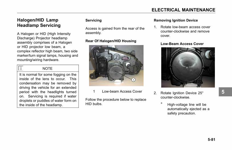
ELECTRICAL MAINTENANCE
Halogen/HID LampHeadlamp Servicing
A Halogen or HID (High IntensityDischarge) Projector headlampassembly comprises of a Halogenor HID projector low beam, acomplex reflector high beam, two sidemarker/turn signal lamps, housing andmounting/wiring hardware.
NOTE
It is normal for some fogging on theinside of the lens to occur. Thiscondensation may be removed bydriving the vehicle for an extendedperiod with the headlights turnedon. Servicing is required if waterdroplets or puddles of water form onthe inside of the headlamp.
Servicing
Access is gained from the rear of theassembly.
Rear Of Halogen/HID Housing
1 Low-beam Access Cover
Follow the procedure below to replaceHID bulbs.
Removing Ignition Device
1. Rotate low-beam access covercounter-clockwise and removecover.
Low-Beam Access Cover
2. Rotate Ignition Device 25°counter-clockwise.
° High-voltage line will beautomatically ejected as asafety precaution.
5-81
5
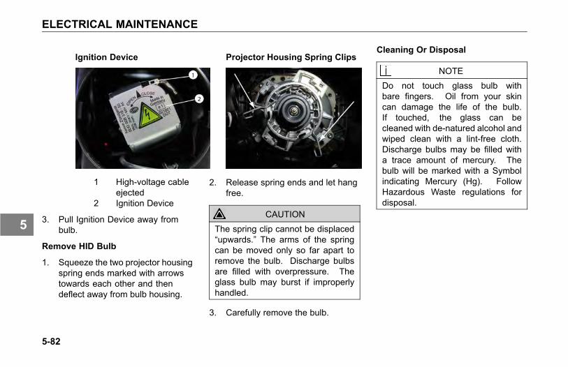
ELECTRICAL MAINTENANCE
Ignition Device
1 High-voltage cableejected
2 Ignition Device
3. Pull Ignition Device away frombulb.
Remove HID Bulb
1. Squeeze the two projector housingspring ends marked with arrowstowards each other and thendeflect away from bulb housing.
Projector Housing Spring Clips
2. Release spring ends and let hangfree.
CAUTIONThe spring clip cannot be displaced“upwards.” The arms of the springcan be moved only so far apart toremove the bulb. Discharge bulbsare filled with overpressure. Theglass bulb may burst if improperlyhandled.
3. Carefully remove the bulb.
Cleaning Or Disposal
NOTEDo not touch glass bulb withbare fingers. Oil from your skincan damage the life of the bulb.If touched, the glass can becleaned with de-natured alcohol andwiped clean with a lint-free cloth.Discharge bulbs may be filled witha trace amount of mercury. Thebulb will be marked with a Symbolindicating Mercury (Hg). FollowHazardous Waste regulations fordisposal.
5-82
5
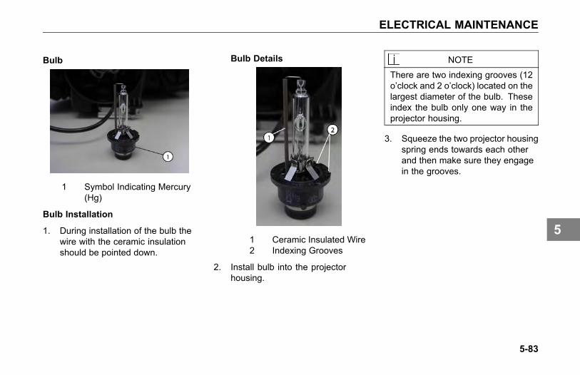
ELECTRICAL MAINTENANCE
Bulb
1 Symbol Indicating Mercury(Hg)
Bulb Installation
1. During installation of the bulb thewire with the ceramic insulationshould be pointed down.
Bulb Details
1 Ceramic Insulated Wire2 Indexing Grooves
2. Install bulb into the projectorhousing.
NOTE
There are two indexing grooves (12o’clock and 2 o’clock) located on thelargest diameter of the bulb. Theseindex the bulb only one way in theprojector housing.
3. Squeeze the two projector housingspring ends towards each otherand then make sure they engagein the grooves.
5-83
5
ELECTRICAL MAINTENANCE
Projector Housing Installation
1 Spring Grooves2 Index Points (12 o’clock
and 2 o’clock)3 White Tab
Ignition Device Installation
CAUTION
Care must be taken to NOT installthe High-voltage cable until afterthe Ignition device is fully installed,otherwise, damage may result toeither the Ignition Device or the HIDBulb.
1. Verify white ring alignment. Ifneeded, carefully rotate ring witha small blunt tool, so that the 4grooves in the housing and ringare aligned or the device cannotbe installed.
2. This tab indexes with white tab onprojector housing (see followingFig.).
Ignition Device
1 White Ring2 Tab
3. Push Ignition Device onto back ofprojector housing.
4. Rotate Ignition Device 25°clockwise until it locks into place.
5. Lastly, install the high-voltagecable to the ignition device.
5-84
5
ELECTRICAL MAINTENANCE
Ignition Device Installed
Close Cover
1. Install and rotate low-beam accesscover clockwise.
Close Low-Beam Access Cover
Final Checks
1. After everything is reconnected,turn on your headlamps and checkfor operation.
2. Have your headlamps periodicallychecked for proper alignment.Headlamps should be adjusted to-0.6° (-1.0%) Vertical.
3. Keep your headlamps clean. Adirty headlamp reduces headlampperformance and creates glare.
° Use only clean soap andwater.
° Your headlamp is coated witha special substance to resistchips and hazing. Harshchemicals and polishing canremove this coating.
5-85
5
ENGINE MAINTENANCE
ENGINE MAINTENANCE
Engine Maintenance
WARNING
Exhaust fumes from the enginecontain carbon monoxide, acolorless and odor less gas. Donot breathe the engine exhaustgas. A poorly maintained, damagedor corroded exhaust system canallow carbon monoxide to enter thecab. Entry of carbon monoxide intothe cab is also possible from othervehicles nearby. Failure to properlymaintain your vehicle could causecarbon monoxide to enter the caband cause illness or death.
WARNING
Never idle your vehicle for prolongedperiods of time if you sense thatexhaust fumes are entering the cab.Investigate the cause of the fumesand correct it as soon as possible.If the vehicle must be driven underthese conditions, drive only with thewindows open. Failure to repairthe source of the exhaust fumesmay result in personal injury, death,equipment or property damage.
NOTEKeep the engine exhaust systemand the vehicles cab ventilationsystem properly maintained.
It is recommended that the vehiclesexhaust system and cab be inspected:
• By a competent technician every15,000 miles
• Whenever a change is noticed inthe sound of the exhaust system
• Whenever the exhaust system,underbody or cab is damaged
5-86
5
ENGINE MAINTENANCE
Engine Lubrication
Refer to the engine manufacturer'sEngine Operation and MaintenanceManual supplied with your vehicle forinformation about draining and refillingengine oil, engine crank case capacity,engine oil type, and changing oil filters,etc.
WARNING
Hot engine oil can be dangerous.You could be burned. Let the engineoil cool down before changing it.Failure to comply may result inpersonal injury, death, equipment orproperty damage.
Inspection of the Engine Oil Level
NOTEIt takes approximately 15 minutesfor all the oil to run into the sumpwhen the engine is ‘warm.’ If thelevel is checked immediately afterswitching off the engine, the dipstickwill show a low oil level.
1. Make sure that the vehicle framerail is standing on a flat and levelsurface.
2. Make sure that the vehicle ishorizontal, both lengthwise andcrosswise. Check this carefullyon a vehicle with air suspension.Note that the engine may beinclined up to 4° depending on thevehicle model and wheelbase.
3. Twist the dipstick handle to unlockit, then pull the dipstick out of theholder.
4. Wipe the dipstick clean with alint-free cloth.
5. Place the dipstick back into theholder.
6. Pull the dipstick out again andcheck the oil level. The oil levelshould always be between the 2marks on the dipstick.
5-87
5
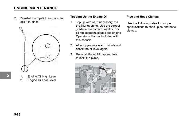
ENGINE MAINTENANCE
7. Reinstall the dipstick and twist tolock it in place.
1. Engine Oil High Level2. Engine Oil Low Level
Topping Up the Engine Oil
1. Top up with oil, if necessary, viathe filler opening. Use the correctgrade in the correct quantity. Foroil replacement, please see engineOperator’s Manual included withthis chassis.
2. After topping up, wait 1 minute andcheck the oil level again.
3. Reinstall the oil fill cap and twistto lock it in place.
Pipe and Hose Clamps
Use the following table for torquespecifications to check pipe and hoseclamps.
5-88
5

ENGINE MAINTENANCE
Table 13 Pipe and Hose Clamp Torque Values
TORQUEAPPLICATION APPROVED CLAMPNm Lb-In
Radiator & Heat Exchanger Hoses Constant-Torque CT-L 10.2-12.5 90-110Heater Hoses Constant Tension not required not requiredAir Intake Pipes Hi-Torque HTM-L 11.3-14.2 100-125
Flex Seal 667 7.9-11.3 70-100Charge Air Intake HosesB9296 6-7 50-60
Fuel, Oil & Water Heat Exchangers (forhoses less than 9/16 diameter)
Miniature 3600L 1.1-1.7 10-15
Exhaust Clamps Breeze V-Band 54 480
Fuel System
Please follow these recommendationswhen you are changing your fuel filtersor strainer elements. Your vehicle'sengine will run better and last longer ifyou do. See the engine manufacturer'srecommendations for proper water andmicron requirements.
Installing Fuel Filters
When removing filters, cover anyelectrical equipment and wiring thatmight get soaked with fuel. Diesel fuelmay permanently damage electricalinsulation.
When installing spin-on (throwaway)filters:
1. Pre-fill filter with fuel.
2. Moisten gasket with diesel fuel
3. Hand tighten them only to 1/2 - 2/3turn after gasket contact.Mechanical tightening of thesefilters may distort or crack the filterhead.
• When replacing a fuel filterelement, do not use a substitute.Install only filter elements designedfor fuel filtration. First clean andinspect the shell. Then insert thenew element and fill the containerat least 2/3 full of clean fuel beforeinstalling the shell.
5-89
5
ENGINE MAINTENANCE
NOTE
To expel air from density-typestrainer elements, soak them inclean fuel before installing them.
• Throw away old gaskets. Replacethem with new ones to ensure apositive seal.
• Position the shell and gasketproperly. Then tighten the covernut or bolt just enough to preventfuel leakage.
• After starting the engine, check forleaks around the filter.
Filter Draining
1. Check fuel filter/water separatordaily. Check with engine OFF.Depending on the fuel storagefacility, more frequent drainingmay be required.
2. Open drain valve (by hand only):turn valve screw counter clockwiseapproximately 1- to 2 turns untildraining occurs. Drain filter sumpof water until clear fuel is visible.
3. If entrapped water exceeds sumpvolume, you can either:
4. Close valve and run engine untilsmooth idle is established, thenrepeat drain procedures.
5. Remove filter from mounting head,completely drain all fluid, andreassemble filter assembly. Besure to follow new filter assemblyinstructions.
6. Close drain valve by turning valvescrew clockwise approximately 1-to 2 turns.
CAUTION
Do not overtighten the valve. Overtightening can damage the threads.
5-90
5

ENGINE MAINTENANCE
Accessory Drive Belts
You can avoid costly downtime byperiodically checking belt wear andreplacing worn and damaged belts.Neglect could cause belt failure. Theresult could be the loss of the electricalor air system as well as possibleengine damage from overheating. So,it is a good idea to check the beltsfrequently and replace them as soonas you detect trouble.
Engine FanThermatic (Clutch) Type Fan
WARNING
Do not work on the fan with theengine running. The engine fan canengage at any time without warning.Anyone near the fan when it turnson could be injured. Before turningon the ignition, be sure that no oneis near the fan.
To Check the Fan:
• Check the fan assembly mountingbolts for tightness. Inspect theblades for damage.
• Check the clutch operation bystarting the engine when it is cold.Then idle it at about 800 rpm.Listen for air leaks.
Fan Drive and Blade
Fan Blade Clearance: Around the fanshroud, the recommended distanceis 1 in. (25 mm) from front edge ofany fan blade-to-radiator side member.Minimum clearance is 3/4 in. (19 mm).
• Rear edge of any blade must beno closer than 3/8 in. (9 mm) tothe nearest engine component. Ifthis cannot be obtained, the fanspacer or fan is not correct.
• The leading edge of any fan blademust be 1 in. (25 mm) from theinside edge of the shroud.
5-91
5
ENGINE MAINTENANCE
Engine Mounting
Periodic Inspection:Inspect newlyinstalled engine mounts every 60,000miles. Check for the following:
• Inspect both mount and legfasteners. Check for looseor broken bolts. Replace asnecessary.
• Check mount and leg for fractures,breaks or deformation. Replaceas necessary.
• Check for complete insertionof motor mount. Replace asnecessary.
• Tighten leg to mount flange headbolts to 210-230 Lb-Ft (284-311Nm) torque.
Exhaust System
The exhaust system is part of thenoise control system. Periodicallycheck the exhaust for wear and looseor missing parts. For details see Noiseand Emission Control on page 5-103.
All Models
Proper operation, driving techniquesand maintenance are key factors inobtaining the maximum service life ofthe muffler and/or converter. Someprecautions should be taken if theengine is equipped with a mufflerand converter. Avoid excess idling.Excessive idling or extended low loadperiods can cause the muffler andconverter to plug. A plugged mufflerand converter will lead to an increasein exhaust back pressure. Operatingthe engine in extremely cold conditionscan cause the muffler and converter toplug sooner. Use the procedure belowto clean out the muffler and converterif extended idle periods or extendedlow load periods are required.
1. Operate the engine at ratedconditions for five to fifteenminutes.
5-92
5
ENGINE MAINTENANCE
2. Contact an authorized EngineService Center, if the enginecontinues to run at low poweror the engine does not respondproperly.
Multi-Function MessageDisplay
The Multi-function Display will displaydiagnostic messages that are intendedto alert you that trouble may bedeveloping in one of the systems, donot ignore these messages, they areimportant indicators that your vehicleshould be serviced immediately.
See your Kenworth Dealer for troubleshooting and diagnostic information.
5-93
5

FRAME MAINTENANCE
FRAME MAINTENANCE
Introduction
WARNING
Do not cut, splice or weld framerails or drill through the top orbottom flanges of the rails. Theseoperations could affect frame railstrength leading to a failure resultingin an accident. Rail failures resultingfrom such modifications are notwarrantable. Failure to complymay result in personal injury, death,equipment or property damage.
Emergency Welding
Kenworth DOES NOT recommendframe welding. The high heat ofwelding nullifies the special heattreatment of the rails, greatly reducingthe tensile strength of the framerail. If a frame member becomescracked from overloading, fatigue,surface damage or a collision, the onlypermanent repair is to replace thedamaged frame member with a newpart. In an emergency, a temporaryrepair may be performed. Observethe following precautions to protectelectronic systems during weldingoperations.
Welding Precautions
In the event of emergency welding of aframe rail and when welding any otherpart of your truck or any componentattached to your truck, observe thefollowing precautions before welding:
• Disconnect all electronic devices.It is not possible to list all of theelectronics that could be affected,but a few examples include thefollowing: alternator, engineElectronic Control Unit (ECU),transmission ECU, ABS ECU,navigation devices, diagnosticdevices, and monitoring devices.
• Disconnect battery cables andinsulate them from the vehicle.
• Do not use the ECU or engineground stud for the ground of thewelding probe.
• Ensure that the ground connectionfor the welder is as close to theweld point as possible. Thisensures maximum weld currentand minimum risk to damageof electrical components on thevehicle.
5-94
5
FRAME MAINTENANCE
Painting
Do not electrostatically paint yourtruck or any component on yourtruck without first removing all ofthe electronic components from thetruck. It is not possible to list all ofthe electronics that could be affected,but a few examples include thealternator, engine Electronic ControlUnit (ECU), transmission ECU, ABSECU, navigation devices, diagnosticdevices, and monitoring devices.
Fifth Wheel Maintenance
Proper preventive maintenance isessential to trouble-free service andsafe operation of the fifth wheel.
Every 2 Months or 25,000 Miles:
• Refer to specific manufacturer'sliterature for any specialinstructions.
• Steam clean the fifth wheel.
• Check lock guard operation usinga commercial lock tester.
• Clean and oil all moving parts.
• Lubricate the following part with alithium-base grease.
° Lock mechanism
• All grease fittings (especially thosewhich grease the top surface ofthe fifth wheel).
Every 6 Months or 50,000 Miles:
• Refer to specific manufacturer'sliterature for any specialinstructions.
• Remove fifth wheel from vehicle.Refer to the Kenworth ShopManual, “Fifth Wheel Removal.”
• Steam clean the fifth wheel andmounting brackets.
• Check all moving parts forexcessive wear or damage.Replace all worn or broken parts.
• Complete two-month serviceprocedure.
• Install fifth wheel. Refer to theKenworth Shop Manual, “FifthWheel Installation.”
5-95
5
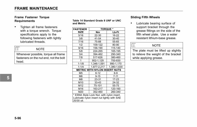
FRAME MAINTENANCE
Frame Fastener TorqueRequirements
• Tighten all frame fastenerswith a torque wrench. Torquespecifications apply to thefollowing fasteners with lightlylubricated threads.
NOTE
Whenever possible, torque all framefasteners on the nut end, not the bolthead.
Table 14 Standard Grade 8 UNF or UNCand Metric
TORQUE *FASTENERSIZE Nm Lb-Ft5/16 22-30 16-223/8 41-54 30-407/16 75-88 55-651/2 109-122 80-909/16 156-190 115-1405/8 224-265 165-1953/4 394-462 290-3407/8 517-626 380-4601 952-1,129 700-830
1-1/8 1,346-1,591 990-1,1701-1/4 1,877-2,217 1,380-1,630
METRIC WITH NYLON INSERT NUTSM5 8-12 6-9M6 9-15 7-11M8 23-31 17-23M10 33-43 24-32M12 75-101 55-75M16 163-217 120-160M20 352-460 260-340
* ESNA Style Lock Nut, with nylon insert.Lubricate nylon insert nut lightly with SAE20/30 oil.
Sliding Fifth Wheels
• Lubricate bearing surface ofsupport bracket through thegrease fittings on the side of thefifth wheel plate. Use a waterresistant lithium-base grease.
NOTE
The plate must be lifted up slightlyto relieve the weight of the bracketwhile applying grease.
5-96
5
FRONT AXLE AND SUSPENSION MAINTENANCE
FRONT AXLEAND SUSPENSIONMAINTENANCE
Axle Lubrication• Change bearing lubrication
when seals are replaced, orbrakes are relined. See Table6, Recommended LubricationIntervals on page 5-11.
• Thoroughly clean hubs andbearings with solvent and a stiffbristle brush, then dry and inspectcomponents for wear or damage.Re-lubricate with approved axlelubricant.
Kingpin Lubrication
• Lubricate with approved lubricant.Lubricate knuckle thrust bearings,knuckle pins, and tie rod ends.See Table 6, RecommendedLubrication Intervals on page5-11. Lack of lubrication causespremature wear and hard steering.Lubrication schedule may beshortened if necessary.
Suspension Lubrication
Each standard spring anchor pin hasa grease fitting. Pressure lubricatespring pins as specified. See Table 6,Recommended Lubrication Intervalson page 5-11.
• At regular intervals, the springleaves may be lubricated with arust-inhibiting oil applied with aspray gun or brush.
• Depending on your suspension,lubricate all spring pins untilgrease flows out of both ends ofthe bushing. Look for signs of rustor water in the flushed grease.If a pin will not accept grease, itshould be removed, cleaned, andinspected.
CAUTIONDo not spray the suspension withchemical products or mineral oil; itcan cause damage to the bushings.
5-97
5
FRONT AXLE AND SUSPENSION MAINTENANCE
Inspection• For all vehicles, mandatory
maintenance procedures includeretightening all U-bolts andinspecting the suspension forloose fasteners, abnormal wear,or damage. However, even withproper maintenance, the servicelife of leaf springs is affected bymany factors, such as: fatigue,vehicle gross weight, type ofload, road conditions, and vehiclespeed.
• Check for cracks, wear marks,splits, or other defects on thesurface of the spring. Defectiveparts must be replaced. Becauserepaired springs cannot befully restored to their originalservice life, replace the completeassembly if cracks or other defectsare detected.
• Visually inspect shock absorbersand rubber bushings.
Wheel Alignment
For driving safety and comfort, andto prolong the life of your vehicle, itis important to have wheels correctlyaligned. Check tire wear frequently.Uneven tire wear is a sign that thewheels may be misaligned.
If you see uneven wear, take yourvehicle to a Kenworth Dealer familiarwith aligning wheels on Kenworthvehicles.
U-Bolt Torque
It is important that U-bolts remain tight.Severe use of your vehicle will causethem to loosen faster. But all vehiclesneed to have their U-bolts checked andtightened regularly. Be sure someonewith the proper training and the righttools checks and tightens the U-boltson your Kenworth.
New springs can settle in after service,relieving the tension on the U-bolts.Loose U-bolts can cause leaf springbreakage, axle misalignment, hardsteering and abnormal tire wear.
• All vehicles should havesuspension U-bolts tightenedafter the first 500 miles (800 km) ofoperation. And re-torque the frontspring pinch bolts and shacklepinch bolts.
5-98
5
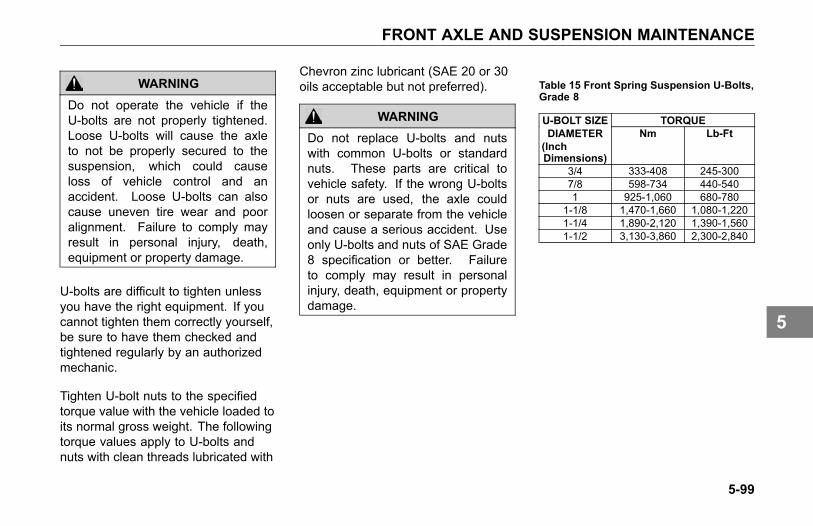
FRONT AXLE AND SUSPENSION MAINTENANCE
WARNING
Do not operate the vehicle if theU-bolts are not properly tightened.Loose U-bolts will cause the axleto not be properly secured to thesuspension, which could causeloss of vehicle control and anaccident. Loose U-bolts can alsocause uneven tire wear and pooralignment. Failure to comply mayresult in personal injury, death,equipment or property damage.
U-bolts are difficult to tighten unlessyou have the right equipment. If youcannot tighten them correctly yourself,be sure to have them checked andtightened regularly by an authorizedmechanic.
Tighten U-bolt nuts to the specifiedtorque value with the vehicle loaded toits normal gross weight. The followingtorque values apply to U-bolts andnuts with clean threads lubricated with
Chevron zinc lubricant (SAE 20 or 30oils acceptable but not preferred).
WARNING
Do not replace U-bolts and nutswith common U-bolts or standardnuts. These parts are critical tovehicle safety. If the wrong U-boltsor nuts are used, the axle couldloosen or separate from the vehicleand cause a serious accident. Useonly U-bolts and nuts of SAE Grade8 specification or better. Failureto comply may result in personalinjury, death, equipment or propertydamage.
Table 15 Front Spring Suspension U-Bolts,Grade 8
TORQUEU-BOLT SIZEDIAMETER(InchDimensions)
Nm Lb-Ft
3/4 333-408 245-3007/8 598-734 440-5401 925-1,060 680-780
1-1/8 1,470-1,660 1,080-1,2201-1/4 1,890-2,120 1,390-1,5601-1/2 3,130-3,860 2,300-2,840
5-99
5
HEATER AND AIR CONDITIONER MAINTENANCE
HEATER AND AIRCONDITIONERMAINTENANCE
Introduction
The combination heater-air conditionerprovides comfort for those in the cabthrough accurate control of the cabenvironment in all weather conditions.Regular attention to the items belowwill help you keep the heater-airconditioner unit running well.
NOTEKeep the vehicles ventilationsystem, engine exhaust system andcab joints properly maintained.
It is recommended that the vehiclesexhaust system and cab be servicedas follows:
• Inspected by a competenttechnician every 15,000 miles
• Whenever a change is noticed inthe sound of the exhaust system
• Whenever the exhaust system,underbody or cab is damaged
NOTE
To allow for proper operation of thevehicle ventilation system, proceedas follows:
• Keep the inlet grille at the base ofthe windshield clear of snow, ice,leaves and other obstructions atall times.
• Keep the exhaust pipe area clearto help reduce the buildup ofexhaust gas under the vehicle.
Special Precautions
WARNING
Excessive heat may cause thepressurized components of the airconditioning system to explode.Never weld, solder, steam clean, oruse a blow torch near any part ofthe air conditioning system. Failureto comply may result in personalinjury, death, equipment or propertydamage.
• If a refrigerant leak develops inthe presence of excessive heator an open flame, hazardousgases may be generated.These gases may causeunconsciousness or death.If you become aware of arefrigerant leak on your vehiclehave your system serviceimmediately and observe thefollowing precautions:
5-100
5
HEATER AND AIR CONDITIONER MAINTENANCE
° Stay away from the hotengine until the exhaustmanifold has cooled.
° Do not permit any openflame in the area. Even amatch or a cigarette lightermay generate a hazardousquantity of poisonous gas.
° Do not smoke in the area.Inhaling gaseous refrigerantthrough a cigarette maycause violent illness.
Heater• Check all heater controls for
full-range operation.
• Check hoses, connections, andheater core for condition andleaks.
• Check the drain tube of the freshair inlet for trapped water beforeassuming that there is a leak in theheating system. If the heater coreis leaking, a reliable radiator shopshould be able to repair it.
• Check the heater core for debrisblocking the air flow. If the blowerand air controls are functioningproperly, yet the heater is notoperating properly, the heatercore or the hot water valves maybe clogged or closed. Clean theheater core if necessary. If thecondition persists, take the vehicleto a Kenworth Dealer for properheater service or repair.
CAUTIONDuring extreme cold weather, donot blow hot defroster air onto coldwindshields. This could crack theglass. Turn the air direction leverto Defrost and adjust the fan speedaccordingly while the engine warms.If the engine is already warm,move the temperature selector toCool, then gradually increase thetemperature when you see that thewindshield is starting to warm-up.
5-101
5
HEATER AND AIR CONDITIONER MAINTENANCE
Air Conditioner
WARNING
The air conditioning system isunder pressure. If not handledproperly during servicing, it couldexplode. Any servicing that requiresdepressurizing and recharging theair conditioning system must beconducted by a qualified technicianwith the right facilities to do thejob. Failure to comply may result inpersonal injury, death, equipment orproperty damage.
• Check the compressor and driveclutch for noise and vibration.If you find problems, have thesystem checked thoroughly. Amalfunctioning clutch usuallyindicates trouble elsewhere in thesystem.
• Check the evaporator core, filter,and condenser core for debrisrestricting air flow. Clean if
necessary. Small particles maybe removed with compressedair blown through the core in theopposite direction of normal airflow.
WARNING
Wear eye protection any timeyou blow compressed air. Smallparticles blown by compressed aircould injure your eyes.
• Inspect and clean cab air filterelement every 3 - 6 monthsof service. Depending on theoperating environment, if air flowfrom the air conditioner and heateris less efficient or windows fogeasier, you may need to replacethe cab air filter.
• Check the compressor belt forcondition and proper tension.
• Check all hoses for kinks,deterioration, chafing, and leaks.
Adjust kinked or chafing hoses toeliminate restrictions and preventfurther wear.
• Check all components andconnections for refrigerant leaks.If you discover a leak, do not try totighten a connection. Tighteninga connection may cause a worseleak. Have a qualified techniciancorrect the problem.
NOTEA leaking evaporator or condensercore cannot be repaired; it must bereplaced.
Have the air conditioning system fullyserviced annually by your KenworthDealer. Qualified service technicianswill have to evacuate and recharge thesystem.
5-102
5
NOISE AND EMISSION CONTROL MAINTENANCE
NOISE ANDEMISSION CONTROLMAINTENANCE
Noise Emission Warranty
Kenworth Truck Company warrantsto the first person who purchases thisvehicle (for purposes other than resale)and to each subsequent purchaser:that this vehicle, as manufacturedby Kenworth Truck Company, wasdesigned, built and equipped toconform, at the time it left Kenworth'scontrol, with all applicable U.S. EPANoise Control Regulations.
This warranty covers this vehicleas designed, built and equipped byKenworth, and is not limited to anyparticular part, component or system ofthe vehicle manufactured by Kenworth.
Defects in design, assembly or in anypart, component or system of thevehicle as manufactured by Kenworth,which at the time it left Kenworth'scontrol caused noise emissionsto exceed Federal standards, arecovered by this warranty for the life ofthe vehicle.
Tampering with Noise ControlSystem
Federal law prohibits the followingacts or the causing thereof:
1. The removal or renderinginoperative by any person otherthan for purposes of maintenance,repair, or replacement, of anydevice or element of designincorporated into any new vehiclefor the purpose of noise controlprior to its sale or delivery to theultimate purchaser or while it is inuse, or
2. The use of the vehicle after suchdevice or element of designhas been removed or renderedinoperative by any person.
Among those acts presumed toconstitute tampering are the acts listedbelow:
5-103
5
NOISE AND EMISSION CONTROL MAINTENANCE
Air Intake System
• Removing or rendering inoperativethe air cleaner/silencers or intakepiping.
Engine Cooling System
• Removing or rendering inoperativethe fan clutch.
• Removing the fan shroud.
Engine
• Removing or rendering enginespeed governor inoperative so asto allow engine speed to exceedmanufacturer's specifications.
• Modifying ECU parameters.
Exhaust System
• Removing or rendering inoperativeexhaust system components.
Fuel System
• Removing or rendering enginespeed governor inoperative,allowing engine speed to exceedmanufacturer's specifications.
• Removing of air signal attenuatoron engines equipped with thisdevice.
Inner Fender Shields and Cab Skirts
• Removing shield or skirts.
• Cutting away parts of shields,skirts or damaged or looseportions of shields or skirts.
Noise Insulating Blankets
• Removing noise insulators fromengine block or from around theoil pan.
• Cutting holes in, or cutting awaypart of noise insulators.
• Removing hood-mounted noiseinsulation.
5-104
5
NOISE AND EMISSION CONTROL MAINTENANCE
Inspection and MaintenanceInstructions
The following instructions are based oninspection of the noise control systemat regular intervals as indicated in theNoise Control System MaintenanceLog on page 5-111.
If, during periodic inspection andmaintenance of other systems andcomponents, it is found that parts of thenoise control system require attention,we recommend that those parts beinspected at more frequent intervalsto assure adequate maintenance andperformance.
Air Intake System
• Do all checks and maintenanceprocedures listed in this manualunder Engine Air Intake Systemand Air Cleaner. See Air Dryer onpage 4-18.
• Check the induction tubing, elbowconnections, clamps, brackets,and fasteners for deterioration,cracks, and security.
• If you find an air leak anywherebetween the air cleaner andthe engine, repair that leakimmediately.
CAUTIONAir leaks cause excessive noise andmay result in serious damage to theengine. If you do not repair them theengine damage will not be coveredby your warranty. Repair all air leaksas soon as you find them.
Engine Mounted Noise Insulators
• Check condition. Is the insulatorsecure? How you do this willdepend on the method of attachingthe noise insulators on the engineand around the oil pan (bolts,snap fasteners, or straps). Tightenloose fasteners and repair orreplace any worn or damagedfasteners.
• Check insulators around fastenersand stress points, especiallywhere they may be affected byengine vibration. Repair anycracked or damaged mountingpoints. Use suitable reinforcingplates to ensure that the insulatorswill remain in position.
5-105
5

NOISE AND EMISSION CONTROL MAINTENANCE
Exhaust System
• Check for exhaust leaks,which would indicate a leakingmanifold gasket; replace gasket ifnecessary.
• Check cap screws for tightness,including those at the flanges.Refer to the engine manufacturer'sservice manual for propertightening sequence and torquevalues.
Joints and Clamps
• Check for leaks, and tighten asnecessary. Check for deteriorationor dents in pipes and clamps whichcould allow exhaust to escape.
Selective Catalyst Reduction (SCR)
• Check SCR canister filter, clampsand mounting brackets. Tighten ifnecessary. Inspect SCR canisterfor signs of rust or corrosion.
5-106
5
NOISE AND EMISSION CONTROL MAINTENANCE
Piping
• Check exhaust piping for rust,corrosion, or damage. Replacedeteriorated piping before holesappear. If piping is perforated atany point, temporary patching orlagging is acceptable until you canhave permanent repairs made.On turbocharged engines, checkjoints at flanges and mountingbrackets for tightness.
Diesel Particulate Filters (DPF)
• Check diesel particulate filter(DPF), clamps, and mountingbrackets. Tighten if necessary.Inspect diesel particulate filter(DPF) for signs of rust or corrosion.
• Check internal baffling. You cando this by listening for rattlingsounds while tapping on the dieselparticulate filter (DPF) with arubber mallet or revving the engineup and down through its normaloperating range.
Mufflers
• Check muffler, clamps, andmounting brackets. Tighten ifnecessary. Inspect muffler forsigns of rust or corrosion.
• Check internal baffling. You cando this by listening for rattlingsounds while tapping the mufflerwith a rubber mallet or revving theengine up and down through itsnormal operating range.
5-107
5
NOISE AND EMISSION CONTROL MAINTENANCE
Exhaust Tail Pipe
• Check the mounting. Tighten asnecessary. The miter cut at the tipof the pipe must be facing the rearof the vehicle. Do not modify theend of the pipe in any way.
Engine Fan and Shroud
WARNING
Do not work on the fan with theengine running. The engine fan canengage at any time without warning.Anyone near the fan when it turnson could be injured. Before turningon the ignition, be sure that no oneis near the fan.
• Check all fasteners for tightness.Check for stress cracks in theshroud. Make sure the shroud isadjusted so that it does not touchthe fan blades.
• Check to verify that the fan isdisengaged (not turning) withthe engine running at normaloperating temperatures (from coldto the point that the fan engages).
• Check fan blade mounting bolts.Inspect fan blades to be sure theyare not cracked or bent.
Transmission and Driveline
• Substituting a different maintransmission or drivelinecomponents, other thandesign-specified units, mayresult in increased vehicle noiseemission.
5-108
5

NOISE AND EMISSION CONTROL MAINTENANCE
Hood Insulation Blanket
• Check all fasteners for conditionand security. Repair or replaceany broken or defective fasteners.
Blanket
• Check for chafing or tears. Patchit if necessary. Find the cause ofthe damage. If any componentor accessory is causing wear ordamage and cannot be relocated,put reinforcing pads on the blanketat the site of wear.
Inner Fender Shields and Cab Skirts
• Check all fasteners, especially theself-tapping hex head screws. Arethey secure? Remove and replaceany loose rivets.
5-109
5
NOISE AND EMISSION CONTROL MAINTENANCE
Shields and Skirts
• Check shields and skirts for cracksat mounting and stress points.Check fender shields for tiremarks, worn spots, or damagefrom objects thrown from tiretreads. You can repair cracked ordamaged fiberglass fender shieldswith fiberglass and resin.
• If you find damage at a fasteningpoint, you can gain additionalstrength by installing a suitablereinforcing plate. This plateshould be drilled to accept a rivetand laminated to the shield withfiberglass and resin.
• Check cab skirts, sills, andbrackets for overall conditionand repair them as necessary.Damaged rubber fender shieldsor cab skirting cannot be repaired.You will need to replace it.
NOTE
Your Kenworth Dealer can performall of these checks and repairs orreplacements.
Noise Control System -Maintenance Log
To ensure your Kenworth's noisecontrol requirements are maintained,record maintenance checks. Use thefollowing log sheet and retain copiesof documents regarding maintenanceservices performed and parts replacedon the vehicle.
5-110
5
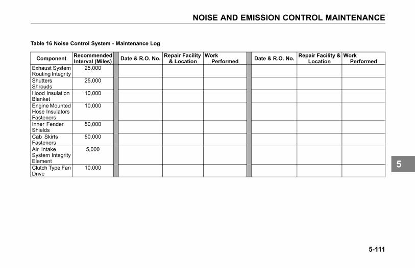
NOISE AND EMISSION CONTROL MAINTENANCE
Table 16 Noise Control System - Maintenance Log
Component RecommendedInterval (Miles) Date & R.O. No. Repair Facility
& LocationWork
Performed Date & R.O. No. Repair Facility &Location
WorkPerformed
Exhaust SystemRouting Integrity
25,000
ShuttersShrouds
25,000
Hood InsulationBlanket
10,000
EngineMountedHose InsulatorsFasteners
10,000
Inner FenderShields
50,000
Cab SkirtsFasteners
50,000
Air IntakeSystem IntegrityElement
5,000
Clutch Type FanDrive
10,000
5-111
5

REAR AXLE AND SUSPENSION MAINTENANCE
REAR AXLE ANDSUSPENSIONMAINTENANCE
General Maintenance
WARNING
Do not work on the vehicle withoutthe parking brake set and wheelschocked securely. If the vehicle isnot secured to prevent uncontrolledvehicle movement, it could roll andmay result in personal injury, death,equipment or property damage.
NOTE
Use wood blocks (4 in. X 4 in.or larger) against the front and rearsurfaces of the tires. Be sure thevehicle cannot move.
Your vehicle's suspension, bydesign, requires a minimal amount ofmaintenance. However, suspensionsin over-the-road operations requireperiodic inspection to ensure trouble-free performance.
WARNING
Do not operate the vehicle if theU-bolts are not properly tightened.Loose U-bolts will cause the axleto not be properly secured to thesuspension, which could causeloss of vehicle control and anaccident. Loose U-bolts can alsocause uneven tire wear and pooralignment. Failure to comply mayresult in personal injury, death,equipment or property damage.
WARNING
Failure to maintain the specifiedtorque values or to replace wornparts can cause component systemfailure, possibly resulting in anaccident. Improperly tightened(loose) suspension U-bolts canlead to unsafe vehicle conditions,including: hard steering, axlemisalignment, spring breakageor abnormal tire wear. SeeFront Spring Suspension U-boltson page 5-99 for proper torquespecifications. Failure to complymay result in personal injury, death,equipment or property damage.
CAUTIONDo not spray the suspension withchemical products or mineral oil; itcan cause damage to the bushings.
5-112
5

REAR AXLE AND SUSPENSION MAINTENANCE
NOTE
Failure to follow theserecommendations could voidwarranty.
Visual Inspection
For all vehicles, mandatorymaintenance procedures includeretightening of U-bolts and completeinspection. However, even with propermaintenance, many factors affect theservice life of springs and suspensioncomponents, such as: fatigue, vehiclegross weight, type of load, roadconditions and vehicle speed.
It is important that U-bolts remain tight.Severe use of your vehicle can causethem to loosen faster. But all vehiclesneed to have their U-bolts checked andtightened regularly. Be sure someonewith the proper training and the righttools checks and tightens the U-boltson your Kenworth.
• After the first 500 miles (800 km) ofoperation, inspect the suspensionperiodically, as noted below:
• Visually check for loose or missingfasteners, cracks in hanger or axleconnection brackets.
• Check that springs are centered inhangers and in good condition.
• Check for cracks, wear marks,splits, or other defects on thesurface of the spring.
• Replace defective parts. Becauserepaired springs cannot befully restored to their originalservice life, replace the completeassembly if cracks or other defectsare detected.
• After replacement of any part ordiscovery of loose components,check the torque of all fasteners.
• New springs settle-in after thevehicle's initial service, causingthe U-bolts to become loose.
5-113
5

REAR AXLE AND SUSPENSION MAINTENANCE
Rear Suspension Fasteners
To maintain the performance of theair suspension, check fastener torquevalues after the first 2,000 miles (3,218km) of service and every 60,000 miles(96,000 km) thereafter.
Torque recommendations apply tofasteners supplied and installedby Kenworth. The values listed inTable 17 and Table 18 below, are forcadmium plated or phosphate and oilfasteners only.
U-bolts are difficult to tighten unlessyou have the right equipment. If youcannot tighten them correctly yourself,be sure to have them checked andtightened regularly by an authorizedmechanic.
U-Bolt Torque
NOTETo ensure an accurate torquereading, use properly maintainedand calibrated torque wrenches.
• Clean the nut and bolt. No dirt,grit, or rust should be present.
WARNING
Do not operate the vehicle if theU-bolts are not properly tightened.Loose U-bolts will cause the axleto not be properly secured to thesuspension, which could causeloss of vehicle control and anaccident. Loose U-bolts can alsocause uneven tire wear and pooralignment. Failure to comply mayresult in personal injury, death,equipment or property damage.
NOTE
Torque all fasteners on the nut end.
Table 17 Rear Suspension Fasteners(Metric & Standard)
TORQUESIZE/TYPENm LbFt
M16nylon-insertnuts
163-217 120-160
M20nylon-insertnuts
352-460 260-340
M20 all-metallock nuts
427-475 315-350
1/2 in. nut 109-122 80-903/4 in. nut 394-462 290-3401-1/4 in. nut 1,877-2,217 1,380-1,630* Torque requirements apply to Kenworthproprietary suspensions. All othersuspensions must refer and adhere tooriginal manufacturers shop manual.
5-114
5
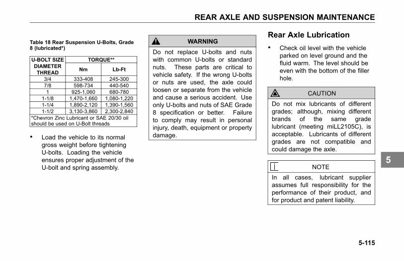
REAR AXLE AND SUSPENSION MAINTENANCE
Table 18 Rear Suspension U-Bolts, Grade8 (lubricated*)
TORQUE**U-BOLT SIZEDIAMETERTHREAD Nm Lb-Ft
3/4 333-408 245-3007/8 598-734 440-5401 925-1,060 680-780
1-1/8 1,470-1,660 1,080-1,2201-1/4 1,890-2,120 1,390-1,5601-1/2 3,130-3,860 2,300-2,840
*Chevron Zinc Lubricant or SAE 20/30 oilshould be used on U-Bolt threads
• Load the vehicle to its normalgross weight before tighteningU-bolts. Loading the vehicleensures proper adjustment of theU-bolt and spring assembly.
WARNING
Do not replace U-bolts and nutswith common U-bolts or standardnuts. These parts are critical tovehicle safety. If the wrong U-boltsor nuts are used, the axle couldloosen or separate from the vehicleand cause a serious accident. Useonly U-bolts and nuts of SAE Grade8 specification or better. Failureto comply may result in personalinjury, death, equipment or propertydamage.
Rear Axle Lubrication• Check oil level with the vehicle
parked on level ground and thefluid warm. The level should beeven with the bottom of the fillerhole.
CAUTION
Do not mix lubricants of differentgrades; although, mixing differentbrands of the same gradelubricant (meeting miLL2105C), isacceptable. Lubricants of differentgrades are not compatible andcould damage the axle.
NOTEIn all cases, lubricant supplierassumes full responsibility for theperformance of their product, andfor product and patent liability.
5-115
5
REAR AXLE AND SUSPENSION MAINTENANCE
For recommended types and brandsof lubricants, contact your KenworthDealer.
Dana Spicer and Fabco
No initial drain is required on DanaSpicer axles that are factory filled withan Dana Spicer-approved syntheticlubricant.
• Petroleum-based lubricants mustbe drained within the first 5,000miles (8,000 km) if converting toan approved synthetic lubricant.
Initial Change: See Table 6,Recommended Lubrication Intervalson page 5-11 for standard rearaxle service intervals. Changemineral-based lubricant in other DanaSpicer and Fabco axle assemblies(new or rebuilt) within the first 3,000 to5,000 miles (4,800 to 8,000 km).
• For petroleum-based axles, uselubricants meeting miL L2105C/Dgrade specifications or approvedsynthetic lubrication. Do not useoil additives.
All Vehicles with Dana Spicerand Fabco Axles: See Table 6,Recommended Lubrication Intervalson page 5-11. Contact your KenworthDealer for approved synthetic lubricantbrands.
• Dana Spicer Axles with syntheticlubrication and Out Runner Seals:drain, flush, and refill at 500,000miles (804,000 km).
5-116
5
REAR AXLE AND SUSPENSION MAINTENANCE
Axle Housing Breather Vent
• Check and clean the axle housingbreather vent at each oil levelcheck.
Meritor
See Meritor Lubrication MaintenanceManual (MM1).
Rear Axle Alignment
Continual road shock and loadstresses may force the rear axlesout of alignment. If you detect rapidtire wear on the rear axles, you mayhave misaligned axles. If you suspectrapid tire wear, have your rear axlealignment checked and adjusted by aKenworth Dealer.
In addition to pre-delivery inspections,suspension alignment should bechecked when any one of the followingconditions exist:
• Discovery of loose suspensionfasteners. (Loose, defined as anytorque below the recommendedtorque value.)
• Discovery of elongated holes in asuspension component.
• Bushing replacement.
• Excessive or abnormal tire wear.
5-117
5
STEERING AND DRIVELINE MAINTENANCE
STEERING ANDDRIVELINEMAINTENANCE
Power Steering
Oil (under low pressure) provides thepower to operate the steering gear. Italso serves to lubricate moving partsand remove heat. A loss of steeringefficiency will occur if too much heatbuilds up in the system.
WARNING
Do not operate the vehicle if thesteering system is not workingproperly. You could lose control ofyour vehicle if the steering system isnot in good working condition, whichcould result in a serious accident.For driving safety, visually checkthe steering gear and components.Frequent checks are importantfor driving safety, especially aftertraveling over rough roads. Failureto comply may result in personalinjury, death, equipment or propertydamage.
NOTE
If the steering feels unbalanced fromside-to-side while turning, check forthe following possible causes:
• unequal tire pressures
• vehicle overloaded or unevenlydistributed load
• wheels out of alignment
• wheel bearings improperlyadjusted
If you cannot correct the problem,check with an authorized KenworthDealer.
The Kenworth is equipped with integralpower steering. The system includesan engine-driven fluid pump, a fluidreservoir, the steering gear, andconnecting hoses. Because of thehydraulic power assist, little effort isrequired to turn the steering wheel.When no input is applied through thesteering wheel, the steering gear willreturn to the neutral position. If, forany reason, the power assist systemgoes out, steering the vehicle is stillpossible, yet it will require muchgreater effort.
5-118
5
STEERING AND DRIVELINE MAINTENANCE
Visually check the following parts:
• Crosstube: Is it straight?
• Draglink tube clamp: Check forlooseness or interference.
• Ball joints and steering U-joints:Check for looseness.
• Steering wheel for excessivefree-play. Check the simplestprobable causes first:
° unequal tire pressures
° loose cap nuts
° bent crosstube
° lack of lubrication
• If these checks do not reveal theproblem, or if you correct themand still have a steering problem,take your truck to an authorizedKenworth Dealer for evaluation.
Fluid Level and Refill
Have the power steering fluid andfilters changed at an authorizedKenworth Dealer.
• Check and completely changethe fluid level according to Table6, Recommended LubricationIntervals on page 5-11. Use thefollowing procedure:
NOTE
Before removing reservoir cover,wipe outside of cover so that no dirtcan fall into the reservoir.
• Maximum/Minimum level isindicated on the reservoir. Thesesame levels are also indicated bytwo lines on the dipstick in thereservoir.
• There are two ways to checkwhether the power steering fluid
is at its proper level. Both checksare with the engine NOT running.
1. If you check the fluid with theengine and steering systemCOLD, the fluid level should beat/or above the Minimum indicatorlevel and should generally notexceed the middle point betweenMaximum and Minimum levelindicators.
2. If you check the fluid with theengine and steering systemWARM, the fluid should NOTexceed the Maximum levelindicator and should generallynot drop below the middle pointbetween the Maximum andMinimum level indicators.
5-119
5
STEERING AND DRIVELINE MAINTENANCE
Fluid Refill
The following recommendations arefor general purpose steering systems,commonly installed on Kenworthvehicles.
• For normal temperatures, useAutomatic Transmission Fluid(ATF) Type E or F or Dexron® III.
• For cold temperatures of -22º F(-30º C) and above use ATF TypeA.
• For extremely cold temperaturesbetween -22º F (-30º C) and -40ºF (-40º C) use ATF Type B.
Steering Driveline
The following are common torquespecifications for most drivelines.
• Torque on U–joint pinch bolt andnut (7/16 in) 74–81 Nm (55 to 60lb-ft), lubricated.
• Torque on Pitman arm clamp boltand nut (3/4 in): 406–433 Nm (300to 320 lb-ft), lubricated.
• For off–highway vehicles, tightenthe U–bolts after the first day ortwo of operation. Then checkweekly.
WARNING
If this chassis is equipped with anelectronic stability system (ESP) andany part of the steering system (e.g.linkage, steering driveline, column,front-end alignment, etc) is repaired,removed, or disassembled in anyway, or if the steering angle sensor isreplaced, the steering angle sensormust be recalibrated. Failure todo so could cause loss of vehiclecontrol. Any repairs or adjustmentsto any part of the steering systemmust be performed by an authorizedKenworth Dealer. Failure to complymay result in personal injury, death,equipment or property damage.Failure to comply may result inpersonal injury, death, equipment orproperty damage.
5-120
5
STEERING AND DRIVELINE MAINTENANCE
Driveshaft
The slip joints and universal joints ofthe drive shaft should be lubricatedperiodically.
• Use a good qualitylithium-soap-base or equivalentextreme pressure (E.P.) grease:NLGI Grade 2.
For Towing Guidelines and Returning aTowed Vehicle to Service see VehicleRecovery Guidelines on page 2-12.
U-Joints
• The slip joints and universaljoints of the drive shaft shouldbe lubricated according to Table6, Recommended LubricationIntervals on page 5-11.
Use a good quality lithium-soap-baseor equivalent extreme pressure (E.P.)grease: NLGI Grade 2.
WARNING
Improper lubrication of U-joints cancause them to fail prematurely. Thedriveshaft could separate from thevehicle and result in an accident.Make sure lubricant is purged at allfour ends of each U-joint and loosencaps if necessary. Also, regularlyinspect U-joints for excessive wearor movement,and repair or replace as necessary.Failure to comply may result inpersonal injury, death, equipment orproperty damage.
5-121
5

TIRES AND WHEEL MAINTENANCE
TIRES AND WHEELMAINTENANCE
Introduction
Keeping the tires in good condition isessential to the safe, efficient operationof your Kenworth. Regular, frequentinspection and the right care will giveyou the assurance of safe and reliabletire operation.
General SafetyRequirements• Each mounting system is
engineered only for use with itscorrect mating part. Be sure thatproperly matched componentsare used for each type ofmounting. The comparisonchart, Comparing Hub-pilotedand Ball-seat Wheels onpage 5-133, illustrates thedifferences between parts usedin hub-piloted mount and ballseat mount applications. OnlyOEM supplied hub-piloted orball-seat mounted wheels maybe used on this vehicle.
WARNING
Use only original equipmentmanufactured (OEM) components.Use of non-original equipment couldcause wheel breakage and wheelseparation from vehicle. Failureto comply may result in personalinjury, death, equipment or propertydamage.
• If you are not fully qualified andnot equipped with the propertools and equipment, do notattempt to raise the vehicle orremove or install the damagedtire and wheel assembly. Obtainexpert help. A person can beinjured and/or damage canresult from using the wrongservice methods. Truck tiresand wheels should be servicedonly by trained personnel usingproper equipment.
5-122
5
TIRES AND WHEEL MAINTENANCE
Do not reinflate a tire that hasbeen run flat or is low on airwithout first removing the tirefrom the rim and inspecting fordamage.
• Follow OSHA regulations persection 1910.177.
• Do not exceed the speed ratingof tires. Exceeding the speedrating may result in suddentire failure and loss of vehiclecontrol.
• Follow all warnings andcautions contained within thetire and wheel manufacturersliterature.
• Only properly trained personnelshould service tire and rimassemblies.
WARNING
Always support the vehicle withappropriate safety stands if it isnecessary to work underneath thevehicle. A jack is not adequatefor this purpose. Failure to complymay result in personal injury, death,equipment or property damage.
Speed Restricted Tires
WARNING
This vehicle may be equippedwith speed restricted tires. Checkeach tires sidewall for maximumrated speed. Vehicle should notbe operated at sustained speed inexcess of maximum rated speed.Failure to comply with these speedrestrictions could cause sudden tirefailure which may result in personalinjury, death, equipment or propertydamage.
5-123
5

TIRES AND WHEEL MAINTENANCE
Tire Inspection andReplacement
Visually inspect your tires frequentlyfor any abnormal conditions such asscrapes, bulges, and uneven wear.This must be done immediately afterknown or suspected contact with anobject in the road, with a pothole,road irregularity or after severebraking. Refer these conditions to anAuthorized Tire Service Center forrepair or replacement. Never drive ona tire if such conditions appear.
If the tire looks under-inflated, standoff to the side and check for damageto the wheel assembly. This can bedone by visually comparing the wheelin question to other wheels on thevehicle. For dual wheel assemblies,check between the wheels for damage.If any damage is found, or you suspectdamage, do not attempt further repair.Call for expert tire service.
Tire Inflation and Loading
Low pressure is a tire's worst enemy.Under-inflation allows tires to fleximproperly, causing high temperaturesto build up. Heat causes early tiredamage such as flex break, radialcracks, and ply separation. And lowpressure may affect control of yourvehicle, especially at the front wheels.
WARNING
Do not operate vehicle withunder-inflated tires. The extra heatcaused by under-inflation can causesudden tire failure such as a tirefire or blow out. Low pressure mayaffect control at the front wheels,which could result in an accident.Keep your tires inflated to themanufacturer's recommended airpressure. Failure to comply mayresult in personal injury, death,equipment or property damage.
Tire Inflation
Most tire wear problems are causedby under-inflation as the result ofslow leaks. So you will want to checktire pressure regularly. Give the tiresa visual test every day, and checkinflation with a gauge every week.
When checking tire pressure, inspecteach tire for damage to sidewalls,cuts, cracks, uneven wear, rocksbetween dual wheels (tires), etc. If atire appears under-inflated, check fordamage to the wheel assembly. Do notforget to check between dual wheels.If you find wheel damage, have anexpert tire service repair it.
5-124
5
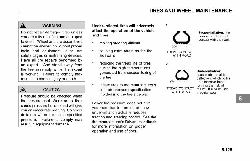
TIRES AND WHEEL MAINTENANCE
WARNING
Do not repair damaged tires unlessyou are fully qualified and equippedto do so. Wheel and tire assembliescannot be worked on without propertools and equipment, such as:safety cages or restraining devices.Have all tire repairs performed byan expert. And stand away fromthe tire assembly while the expertis working. Failure to comply mayresult in personal injury or death.
CAUTIONPressure should be checked whenthe tires are cool. Warm or hot tirescause pressure buildup and will giveyou an inaccurate reading. So neverdeflate a warm tire to the specifiedpressure. Failure to comply mayresult in equipment damage.
Under-inflated tires will adverselyaffect the operation of the vehicleand tires:
• making steering difficult
• causing extra strain on the tiresidewalls
• reducing the tread life of tiresdue to the high temperaturesgenerated from excess flexing ofthe tire
• Inflate tires to the manufacturer'scold air pressure specificationmolded into the tire side wall.
Lower tire pressure does not giveyou more traction on ice or snow.under-inflation actually reducestraction and steering control. See thetire manufacturer's Drivers Handbookfor more information on properoperation and use of tires.
1
TREAD CONTACTWITH ROAD
Proper-Inflation: thecorrect profile for fullcontact with the road.
2
TREAD CONTACTWITH ROAD
Under-Inflation:causes abnormal tiredeflection, which buildsup excessive heat,running the risk offailure. It also causesirregular wear.
5-125
5
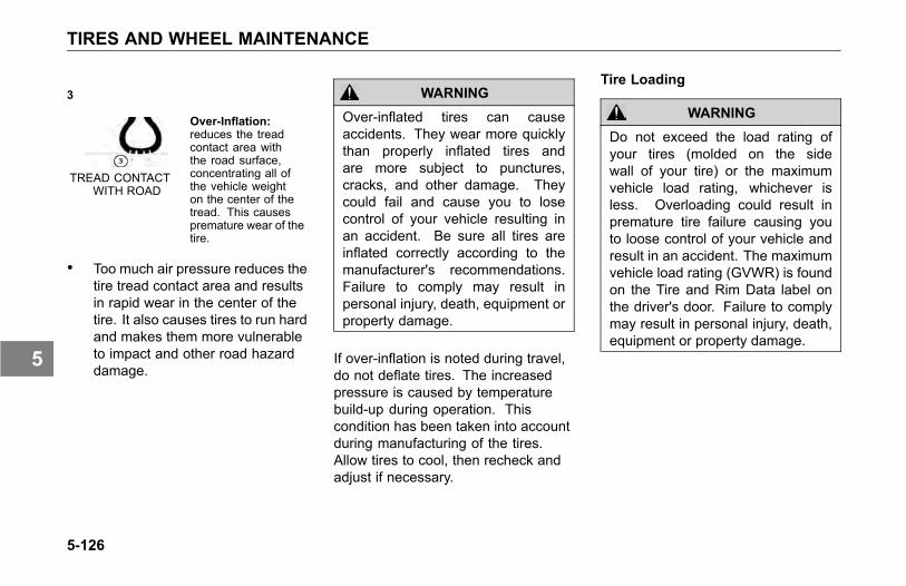
TIRES AND WHEEL MAINTENANCE
3
TREAD CONTACTWITH ROAD
Over-Inflation:reduces the treadcontact area withthe road surface,concentrating all ofthe vehicle weighton the center of thetread. This causespremature wear of thetire.
• Too much air pressure reduces thetire tread contact area and resultsin rapid wear in the center of thetire. It also causes tires to run hardand makes them more vulnerableto impact and other road hazarddamage.
WARNING
Over-inflated tires can causeaccidents. They wear more quicklythan properly inflated tires andare more subject to punctures,cracks, and other damage. Theycould fail and cause you to losecontrol of your vehicle resulting inan accident. Be sure all tires areinflated correctly according to themanufacturer's recommendations.Failure to comply may result inpersonal injury, death, equipment orproperty damage.
If over-inflation is noted during travel,do not deflate tires. The increasedpressure is caused by temperaturebuild-up during operation. Thiscondition has been taken into accountduring manufacturing of the tires.Allow tires to cool, then recheck andadjust if necessary.
Tire Loading
WARNING
Do not exceed the load rating ofyour tires (molded on the sidewall of your tire) or the maximumvehicle load rating, whichever isless. Overloading could result inpremature tire failure causing youto loose control of your vehicle andresult in an accident. The maximumvehicle load rating (GVWR) is foundon the Tire and Rim Data label onthe driver's door. Failure to complymay result in personal injury, death,equipment or property damage.
5-126
5
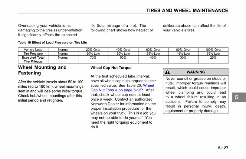
TIRES AND WHEEL MAINTENANCE
Overloading your vehicle is asdamaging to the tires as under-inflation.It significantly affects the expected
life (total mileage of a tire). Thefollowing chart shows how neglect or
deliberate abuse can affect the life ofyour vehicle's tires.
Table 19 Effect of Load Pressure on Tire Life
Vehicle Load Normal 20% Over 40% Over 60% Over 80% Over 100% OverTire Pressure Normal 20% Low 30% Low 35% Low 45% Low 55% LowExpected TotalTire Mileage
Normal 70% 50% 40% 30% 25%
Wheel Mounting andFastening
After the vehicle travels about 50 to 100miles (80 to 160 km), wheel mountingsseat in and will lose some initial torque.Check hub/wheel mountings after thisinitial period and retighten.
Wheel Cap Nut Torque
At the first scheduled lube interval,have all wheel cap nuts torqued to theirspecified value. See Table 20, WheelCap Nut Torque on page 5-127. Afterthat, check wheel cap nuts at leastonce a week. Contact an authorizedKenworth Dealer for information on theproper installation procedure for thewheels on your truck. This is a job youmay not be able to do yourself. Youneed the right torquing equipment todo it.
WARNING
Never use oil or grease on studs ornuts; improper torque readings willresult, which could cause improperwheel clamping and could leadto a wheel failure resulting in anaccident. Failure to comply mayresult in personal injury, death,equipment or property damage.
5-127
5

TIRES AND WHEEL MAINTENANCE
Wheel Bearing Adjustment
For safe, reliable operation andadequate service life, your wheelbearings must be adjusted properly atthe recommended intervals. See Table9, Maintenance Schedule on page5-17 and Steering Axle Wheel Bearing- End Play Adjustment and Inspectionon page 5-17. Contact your authorizedKenworth Dealer to make sure thewheel bearings are properly adjusted.
5-128
5
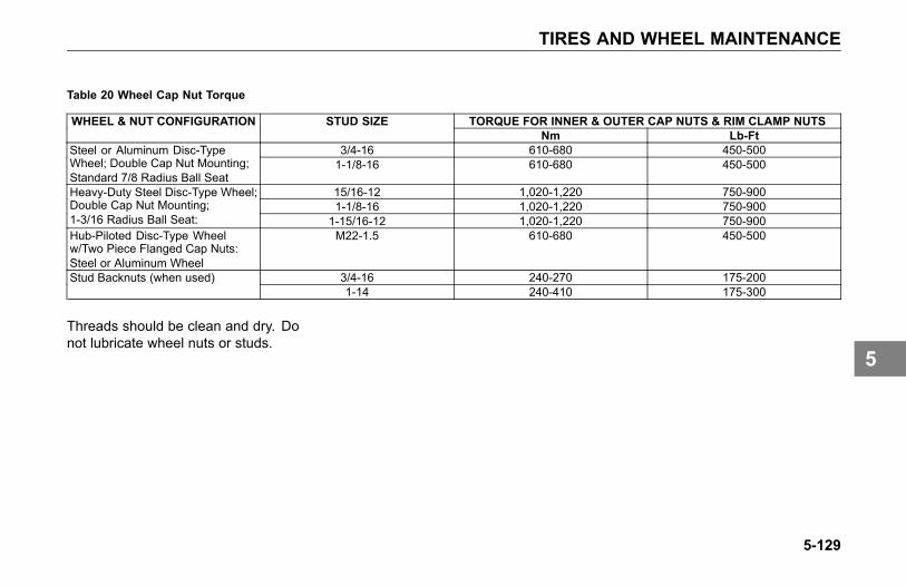
TIRES AND WHEEL MAINTENANCE
Table 20 Wheel Cap Nut Torque
TORQUE FOR INNER & OUTER CAP NUTS & RIM CLAMP NUTSWHEEL & NUT CONFIGURATION STUD SIZENm Lb-Ft
3/4-16 610-680 450-500Steel or Aluminum Disc-TypeWheel; Double Cap Nut Mounting;Standard 7/8 Radius Ball Seat
1-1/8-16 610-680 450-500
15/16-12 1,020-1,220 750-9001-1/8-16 1,020-1,220 750-900
Heavy-Duty Steel Disc-Type Wheel;Double Cap Nut Mounting;1-3/16 Radius Ball Seat: 1-15/16-12 1,020-1,220 750-900Hub-Piloted Disc-Type Wheelw/Two Piece Flanged Cap Nuts:Steel or Aluminum Wheel
M22-1.5 610-680 450-500
3/4-16 240-270 175-200Stud Backnuts (when used)1-14 240-410 175-300
Threads should be clean and dry. Donot lubricate wheel nuts or studs.
5-129
5
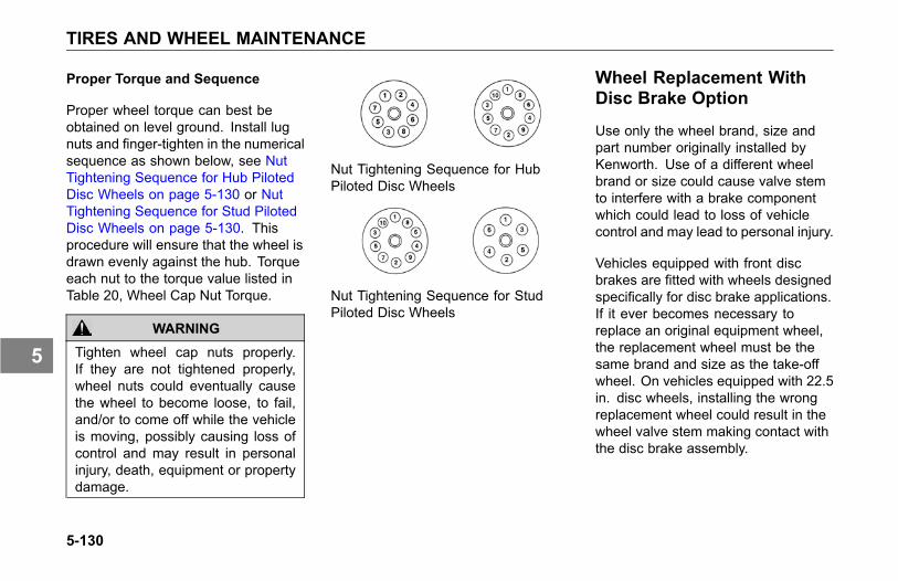
TIRES AND WHEEL MAINTENANCE
Proper Torque and Sequence
Proper wheel torque can best beobtained on level ground. Install lugnuts and finger-tighten in the numericalsequence as shown below, see NutTightening Sequence for Hub PilotedDisc Wheels on page 5-130 or NutTightening Sequence for Stud PilotedDisc Wheels on page 5-130. Thisprocedure will ensure that the wheel isdrawn evenly against the hub. Torqueeach nut to the torque value listed inTable 20, Wheel Cap Nut Torque.
WARNING
Tighten wheel cap nuts properly.If they are not tightened properly,wheel nuts could eventually causethe wheel to become loose, to fail,and/or to come off while the vehicleis moving, possibly causing loss ofcontrol and may result in personalinjury, death, equipment or propertydamage.
Nut Tightening Sequence for HubPiloted Disc Wheels
Nut Tightening Sequence for StudPiloted Disc Wheels
Wheel Replacement WithDisc Brake Option
Use only the wheel brand, size andpart number originally installed byKenworth. Use of a different wheelbrand or size could cause valve stemto interfere with a brake componentwhich could lead to loss of vehiclecontrol and may lead to personal injury.
Vehicles equipped with front discbrakes are fitted with wheels designedspecifically for disc brake applications.If it ever becomes necessary toreplace an original equipment wheel,the replacement wheel must be thesame brand and size as the take-offwheel. On vehicles equipped with 22.5in. disc wheels, installing the wrongreplacement wheel could result in thewheel valve stem making contact withthe disc brake assembly.
5-130
5
TIRES AND WHEEL MAINTENANCE
When installing any replacementwheel, always inspect the tires/wheelsto ensure there is adequate clearancebetween other vehicle components.
With the hood open, check forclearance between the wheel and discbrake assembly. Use a hydraulic jackto raise the front of the vehicle offthe ground to allow the wheel to spinfreely. While rotating the wheel, checkto ensure there is adequate clearancebetween the wheel and disc brakeassembly
WARNING
If the hood falls, anyone under itcould be injured. Always attach thesafety cable and/or hood stop whenthe hood is in its open position anytime anyone gets under the hoodfor any reason. Failure to complymay result in personal injury, death,equipment or property damage.
WARNING
Always support the vehicle withappropriate safety stands if it isnecessary to work underneath thevehicle. A jack is not adequate forthis purpose.
WARNING
Improperly mounting anddemounting tire and rim assembliesis dangerous. Failure to observeproper precautions could causethe tire-rim assembly to burstexplosively, causing seriousinjury or death. See the wheelmanufacturer's literature for theproper way to mount and demountyour tires and rims. Follow theirprecautions exactly.
Disc Wheels
WARNING
Use the correct components andtools when working on wheels.Grooves in the wheel disc or otherdamage to the disc can weaken thewheel and cause it to eventuallycome off. This could cause you tolose control of your vehicle, andmay result in an accident. Failureto comply may result in personalinjury, death, equipment or propertydamage.
The end of the wheel wrench mustbe smooth. Burrs on the end of thewrench can tear grooves in the disc.These grooves may lead to cracks inthe disc, and can cause it to fail.
5-131
5
TIRES AND WHEEL MAINTENANCE
Comparing Hub Piloted andBall Seat Parts
WARNING
Do not mismatch wheelcomponents. Equipment thatdoes not exactly match originalspecifications or that is mismatchedcould cause the wheels to breakand separate from the vehicle. Theresulting accident could be veryserious. Each mounting systemis engineered for use only withits correct mating part. Be sureproperly matched components areused for each type of mounting.Failure to comply may result inpersonal injury, death, equipment orproperty damage.
The following comparison (Table 21,Comparing Hub-piloted and Ball-seatWheels), shows the differencebetween parts used in hub pilot mountand ball seat mount applications.
5-132
5
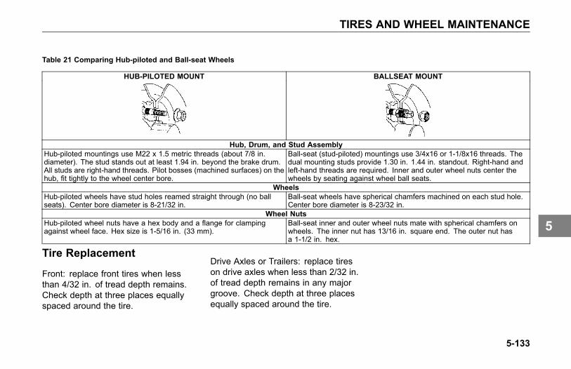
TIRES AND WHEEL MAINTENANCE
Table 21 Comparing Hub-piloted and Ball-seat Wheels
HUB-PILOTED MOUNT BALLSEAT MOUNT
Hub, Drum, and Stud AssemblyHub-piloted mountings use M22 x 1.5 metric threads (about 7/8 in.diameter). The stud stands out at least 1.94 in. beyond the brake drum.All studs are right-hand threads. Pilot bosses (machined surfaces) on thehub, fit tightly to the wheel center bore.
Ball-seat (stud-piloted) mountings use 3/4x16 or 1-1/8x16 threads. Thedual mounting studs provide 1.30 in. 1.44 in. standout. Right-hand andleft-hand threads are required. Inner and outer wheel nuts center thewheels by seating against wheel ball seats.
WheelsHub-piloted wheels have stud holes reamed straight through (no ballseats). Center bore diameter is 8-21/32 in.
Ball-seat wheels have spherical chamfers machined on each stud hole.Center bore diameter is 8-23/32 in.
Wheel NutsHub-piloted wheel nuts have a hex body and a flange for clampingagainst wheel face. Hex size is 1-5/16 in. (33 mm).
Ball-seat inner and outer wheel nuts mate with spherical chamfers onwheels. The inner nut has 13/16 in. square end. The outer nut hasa 1-1/2 in. hex.
Tire Replacement
Front: replace front tires when lessthan 4/32 in. of tread depth remains.Check depth at three places equallyspaced around the tire.
Drive Axles or Trailers: replace tireson drive axles when less than 2/32 in.of tread depth remains in any majorgroove. Check depth at three placesequally spaced around the tire.
5-133
5

TIRES AND WHEEL MAINTENANCE
WARNING
Do not install regrooved orreinforcement- repaired tires onsteering axles. They could failunexpectedly and cause you tolose control of your vehicle resultingin an accident. Failure to complymay result in personal injury, death,equipment or property damage.
WARNING
Do not replace original equipmenttires with load ratings less than theoriginal tires. Doing so could leadto unintentional overloading of thetire, which could cause a failureresulting in loss of vehicle controland an accident. Failure to complymay result in personal injury, death,equipment or property damage.
NOTE
To prolong the tires' life and makethem safer, have their radial andlateral run-out checked at yourKenworth Dealer. And of coursehave the tires balanced any timeyou change a tire.
5-134
5

TIRES AND WHEEL MAINTENANCE
Matching Tires
Be sure to buy matched tires foryour vehicle, especially on the rearaxles. Mismatched tires can causestress between axles and cause thetemperature of the axle lubricant to gettoo hot. Matched tires will help thedriveline last longer and will give youbetter tire mileage.
WARNING
Do not mismatch tires, it can bedangerous. Never mix tires ofdifferent design such as steel beltedradials and bias ply tires, etc. Mixingtire types and sizes will adverselyaffect the road-holding ability of bothtypes of tires and can lead to lossof vehicle control. Failure to complymay result in personal injury, death,equipment or property damage.
Make sure, too, that you use the rightsize tires on each wheel. Some trucks
require different sizes on front and rearwheels. For safety, always use therecommended size and type of tires.
5-135
5
TRANSMISSION AND CLUTCH MAINTENANCE
TRANSMISSIONAND CLUTCHMAINTENANCE
Introduction
Follow the procedures below toensure parts are properly lubricated:
• Maintain oil level, check it regularly
• Change oil regularly
• Use the correct grade and type ofoil
• Buy oil from a reputable dealer
All Transmissions
Initial Change: drain and replaceaccording to Table 6, RecommendedLubrication Intervals on page 5-11; forsome transmissions this may not berequired.
Oil Change
Change fluid according to changeprocedures specified in theTransmission Service Manual.Use the recommended types of oilas specified in the Operation andService Manual (included with vehicle).Select from the appropriate lubricantfor varying ambient (outside air)temperatures.
5-136
5
TRANSMISSION AND CLUTCH MAINTENANCE
Transmission Lubricants
CAUTIONWhen adding oil, types andbrands of oil should not beintermixed because of possibleincompatibility, which coulddecrease the effectiveness of thelubrication or cause componentfailure.
Manual Transmission
Manual transmissions are designed sothat the internal parts operate in a bathof oil circulated by the motion of gearsand shafts.
Service Intervals
For recommended types and brandsof all lubricants, see the transmissionmanufacturer's Service Manual andTable 6, Recommended LubricationIntervals on page 5-11.
Check all hoses for kinks, deterioration,chafing, and leaks. Adjust kinked orchafing hoses to eliminate restrictionsand prevent further wear. To ensureproper inspection, it may be necessaryto inspect under and inside frame railsand unclip harnesses, hoses and cablebundles.
5-137
5

TRANSMISSION AND CLUTCH MAINTENANCE
Standard Transmission Oil Level
NOTEThe vehicle must be parked onlevel ground.See the TransmissionOperator's Manual for informationon checking the transmission oillevel.
Automatic TransmissionsService Intervals
Check daily with engine idling. SeeTable 6, Recommended LubricationIntervals on page 5-11 for serviceintervals.
Automatic Transmission Oil Level
NOTEThe vehicle must be parked on levelground.
See the Transmission Operator'sManual for information on checking thetransmission oil level.
5-138
5
TRANSMISSION AND CLUTCH MAINTENANCE
Clutch System Introduction
Free pedal is the distance the clutchpedal moves by applying only slightpressure. During free pedal therelease yoke in the transmissionmoves until its bearing pads contactthe release bearing. This movement ofthe release yoke is called free travel.Thus, free pedal and free travel aredirectly related to each other.
As the clutch pedal is depressedfurther, with harder pressure, therelease yoke moves the releasebearing away from the engine. Thiscauses the clutch plate to release fromthe driven disks in the clutch. This iscalled release travel. And finally, as thepedal is pushed to the last 1/2 to 1 inchof travel, the release bearing contactsand engages the clutch brake. Thisis called clutch brake squeeze. Whenthe clutch wears, the release bearinggradually moves toward the engine,decreasing free pedal and free travel.
When all free pedal and free travel aregone, the clutch requires adjustment.
The clutch is adjusted by turning anadjustment ring that is built into theclutch. When the ring is turned, therelease bearing moves back towardthe transmission, restoring free pedaland clutch free travel. Under normalclutch wear this is the only adjustmentneeded. Do not attempt to change anyother component.
Clutch Linkage
Have your authorized KenworthDealer service the clutch accordingto the clutch manufacturer's serviceguidelines.
• The Kenworth is equipped with arod and lever mechanical clutchlinkage. Lubricate each pivot pointon the clutch linkage.
5-139
5
TRANSMISSION AND CLUTCH MAINTENANCE
Clutch Adjustment - NormalWear
See the clutch manufacturer's ServiceManual for the proper adjustmentprocedures.
NOTEThis procedure is all that isrequired for normal clutchadjustment. Adjustment of anyother components is not required.
External Linkage Adjustment
1. Adjust clutch to clutchmanufacturer's specification.
2. Verify 1/8 in. free travel (distancethe release yoke moves before therelease yoke bearing pads contactthe release bearing).
3. Verify free pedal of 1.75 in. (44mm ± 6 mm).
5-140
5

INFORMATION
CONSUMER INFORMATION AND VEHICLE IDENTIFICATIONIntroduction . . . . . . . . . . . . . . . . . . 6-3Reporting Safety Defects . . . . . . . . . . . . 6-3Vehicle Identification . . . . . . . . . . . . . . 6-4Certification Labels . . . . . . . . . . . . . . . 6-5Component Identification. . . . . . . . . . . . . 6-8
6-1
6

CONSUMER INFORMATION AND VEHICLE IDENTIFICATION
CONSUMERINFORMATIONAND VEHICLEIDENTIFICATION
Introduction
WARNING
This vehicle contains materialknown by the State of California tocause cancer and/or birth defectsor other reproductive harm. Thiswarning requirement is mandatedby California law (Proposition 65)and does not result from any changein the manner in which Kenworthtrucks are manufactured.
Reporting Safety Defects
United States
If you believe that your vehicle hasa defect which could cause a crashor could cause injury or death, youshould immediately inform the NationalHighway Traffic Safety Administration(NHTSA) in addition to notifyingKenworth Truck Company.
If NHTSA receives similar complaints,it may open an investigation, andif it finds that a safety defect existsin a group of vehicles, it may ordera recall and remedy campaign.However, NHTSA cannot get involvedin individual problems between you,your Kenworth Dealer, and KenworthTruck Company.
To contact NHTSA, you may eithercall the Auto Safety Hotline toll-freeat 1-800-424-9393 (366-0123 inWashington, D.C.) or write to:
Administrator, NHTSA, 400 SeventhStreet, S.W., Washington, D.C. 20590.You can also get other informationabout auto safety from the Hotline.
Canada
Canadian customers whowish to reporta safety-related defect to TransportCanada, Defect Investigations andRecalls, may telephone the toll freehotline 1-800-333-0510, or contactTransport Canada bymail at: TransportCanada, ASFAD, Place de Ville TowerC, 330 Sparks Street, Ottawa ON K1A0N5.
For additional road safety information,please visit the Road Safety websiteat:
http://www.tc.gc.ca/roadsafety/menu.htm
6-3
6
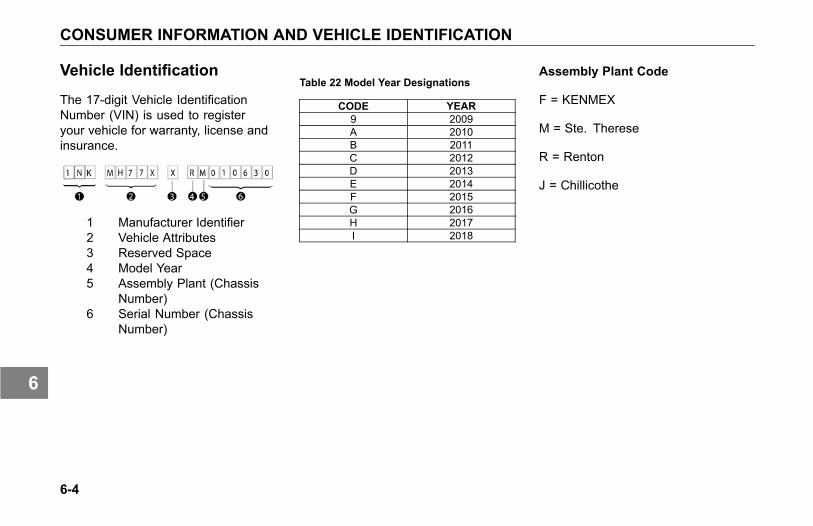
CONSUMER INFORMATION AND VEHICLE IDENTIFICATION
Vehicle Identification
The 17-digit Vehicle IdentificationNumber (VIN) is used to registeryour vehicle for warranty, license andinsurance.
1 Manufacturer Identifier2 Vehicle Attributes3 Reserved Space4 Model Year5 Assembly Plant (Chassis
Number)6 Serial Number (Chassis
Number)
Table 22 Model Year Designations
CODE YEAR9 2009A 2010B 2011C 2012D 2013E 2014F 2015G 2016H 2017I 2018
Assembly Plant Code
F = KENMEX
M = Ste. Therese
R = Renton
J = Chillicothe
6-4
6
CONSUMER INFORMATION AND VEHICLE IDENTIFICATION
VIN Location
The full, 17-digit VIN is exclusivelylocated on the Weight Rating DataLabel. The label is located on thedriver's side door edge or on thedriver's side door frame.
Chassis Number
The Chassis Number refers to thelast seven characters of the VIN.This number will allow your KenworthDealer to identify your vehicle. You willbe asked for this number when youbring it in for service.
Chassis Number Locations
• Right frame rail, top flange, about3 ft. from the front end
• Cab back, left-hand rear panel,lower edge
• Tire, Rim, and Weight Rating Datalabel (truck)
• Components and Weights label
• Noise Emission label
• Paint Identification label
Certification Labels
Vehicle information and specificationsfor your Kenworth are documented onlabels. As noted below, each labelcontains specific information pertainingto vehicle capacities and specificationsthat you should be aware of.
6-5
6
CONSUMER INFORMATION AND VEHICLE IDENTIFICATION
Components and Weights Label
The Components and Chassis WeightLabel is located on either the driver’sside door edge or on the driver’sside door frame. It includes chassisnumber, chassis weight and grossweight, plus model information for thevehicle, engine, transmission, andaxles.
Tire and Rim Data Label
The Tire, Rim And Weight RatingData Label is located on the driver’sside door edge or on the driver’s sidedoor frame. It contains the followinginformation:
• GVWR - Gross Vehicle WeightRating
• GAWR FRONT, INTERMEDIATEand REAR - Gross Axle WeightRatings for Front, Intermediateand Rear Axle
• TIRE/RIM SIZES AND INFLATIONPRESSURES - Tire/Rim Sizesand Cold Pressure Minimums
• VIN including CHASSIS NUMBER
WARNING
Do not exceed the specified loadrating. Overloading can result inloss of vehicle control and personalinjury, either by causing componentfailures or by affecting vehiclehandling. Exceeding load ratingscan also shorten the service life ofthe vehicle.
The components of your vehicleare designed to provide satisfactoryservice if the vehicle is not loadedin excess of either the gross vehicleweight rating (GVWR), or the maximumfront and rear gross axle weight ratings(GAWRs).
NOTE
GVW is the TOTAL SCALEWEIGHTthe vehicle is designed to carry.This includes the weight of theempty vehicle, loading platform,occupants, fuel, and any load.
6-6
6

CONSUMER INFORMATION AND VEHICLE IDENTIFICATION
Noise Emission Label
The Noise Emission Label is locatedin the drivers side door frame. Itcontains information regarding U.S.noise emission regulations, chassisnumber, and date of manufacture.
Paint Identification Label
The Paint Identification Label containsthe paint colors used by the factoryto paint your vehicle. It lists frame,wheels, cab interior and exteriorcolors. This label is located inside theglove box.
Federal Safety StandardCertification Label
The NHTSA regulations require a labelcertifying compliance with FederalSafety Standards, for United Statesand U.S. Territories, be affixed toeach motor vehicle and prescribewhere such label may be located.This certification label, which indicatesthe date of manufacture and otherpertinent information, is located onthe driver’s side door edge or on thedriver’s side door frame.
6-7
6

CONSUMER INFORMATION AND VEHICLE IDENTIFICATION
Component Identification
Each of the major components onyour vehicle has an identification labelor tag. For easy reference, recordcomponent numbers such as, model,serial, and assembly number.
Engine: For further information,please refer to the Engine Operationand Maintenance Manual.
Transmission: For both manualand automatic transmissions, theidentification number is stamped on atag affixed to the right rear side of thetransmission case.
Clutch: Enclosed in clutch housing.Location depends on manufacturer.
Steer Axle: The front axle serialnumber is stamped on a plate locatedon the center of the axle beam.
Drive Axles: The drive axle numberingsystem includes three labels or stamps:
1. Axle Specification Number, usuallystamped on the right rear side ofthe axle housing. This numberidentifies the complete axle.
2. Axle Housing Number Tag, usuallylocated on the left forward sideof the housing arm. This tagidentifies the axle housing.
3. Axle Differential CarrierIdentification, usually locatedon the top side of the differentialcarrier. The following informationis either stamped, or marked with ametal tag: Model No., ProductionAssembly No., Serial No., GearRatio, and Part Number.
6-8
6

Index
Index5th wheel
maintenance 5-95
AAbout This Manual 1-3Accessories
cigarette lighter 3-6radio 3-6
Adding electrical options 5-68Additional sources of information 1-7
california proposition 65warning 1-7data recorder 1-8installed equipment - operator'smanuals 1-7other sources 1-7
Adjustable auxiliary axles 4-56liftable/non-steerable pushercalibration 4-60liftable/steerable calibration 4-60tag axle calibration 4-60
Adjustments 5-45
Air cleaner and filter 5-42Air cleaner restriction gauge 5-42Air compressor 5-37Air dryer 4-18, 5-39Air dryer (Bendix AD-IS series) 5-40Air dryer overhaul 5-40Air filter restriction pressuregauge 3-52
Air gaugesair filter restriction pressure 3-52air pressure #1 & #2 3-60air pressure - air suspension airbags #1 & #2 3-62brake application air pressure 3-54pusher axle(s) air pressure 3-53tag axle air pressure 3-54tractor air brake pressure 3-63tractor air brake pressure -primary/secondary 3-61trailer air brake pressure 3-63trailer air tank pressure 3-64
Air intake system 5-41
Air systemair cleaner 5-42air compressor 5-37air dryer 5-39air gauges and air leaks 5-36air intake system 5-41draining air tanks 5-35filter elements 5-42primary air pressure gauge 5-36scheduled maintenance 5-34scheduled maintenance table 5-34secondary air pressure gauge 5-36turbocharger 5-42
Air system maintenance 5-33Air tanks 5-35Alarms 3-66
engine oil pressure 3-21fifth wheel slide 3-22low air warning alarm - primary 3-20low air warning alarm -secondary 3-20low coolant level 3-22
Index-1
7
Index
park brake 3-21stop engine alarm 3-20turn signal/hazard 3-23
Alert screensalarm clock active 3-69circuit failure 3-69cruise control 3-69cruise control rationality 3-67DEF 3-68disabled alert 3-73engine over-speed shutdown lowair warning 3-70engine protection shutdowntimer 3-70fault alert 3-72front drive axle speed warning 3-70hydrocarbon burn 3-69impact alert 3-72lamp faults 3-67level 1 following distance alert 3-72level 2 following distance alert 3-71level 3 following distance alert 3-71low voltage disconnect 3-68no-idle shutdown 3-67not available alert 3-73over-crank protection 3-68
park brake on while moving 3-67SCR/DEF 3-68stationary object alert 3-72trailer detect 3-68water in fuel (WIF) 3-69Wingman® ACB alert screens 3-71
Ammeter 3-52Analog clock 3-7Anti-lock brakes 4-27
trailer ABS 4-31trailer ABS (without PLC) 4-32wheel spin control 4-28
Appliances 3-8Ashtray 3-7Audible alerts 3-17Automatic transmissions
auxiliary transmission 4-71oil level 5-138operation 4-70service intervals 5-138
Auxiliary axles 4-56Axle
Steerable Drive Axle 4-71
BBatteries
battery access 5-73battery care 5-76battery charging 5-77jump starting vehicles 2-9removing and installingbatteries 5-76
Brake air pressure gauge 3-54Brake gauges
brake pedal or trailer brake handvalve pressure 3-54tractor air brake pressure 3-63tractor primary/secondary air brakepressure 3-61trailer air brake pressure 3-63trailer air tank pressure 3-64
Brake system 4-17air supply system 4-18anti-lock brakes 4-27anti-lock braking system(ABS) 5-48automatic (slack) adjusters 5-46brake adjuster stroke 5-47brake and slack adjusterlubrication 5-45
Index-2
7

Index
brake component descriptions 4-36brake linings 5-45cam-actuated componentlubrication 5-44emergency braking 4-26engine brake 4-35engine retarders 4-33exhaust brake 4-34front brakes 4-19modulating valve 4-19overheated brakes 4-27parking brake system 4-20parking brake valve 4-20releasing combination ofbrakes 4-22releasing trailer brakes 4-22releasing truck or tractor parkingbrakes 4-21safety - tractor/trailer 4-26system park tractor 4-25tractor/trailer air supply valve 4-23trailer brake hand valve 4-32trailer charge 4-25trailer emergency brakeapplication 4-24trailer parking brake 4-24
treadle valve - front circuit 4-19treadle valve - rear circuit 4-20wet brake components 4-19
Brake system maintenance 5-43
CCab and frame access 1-21Cab storage 3-7
ashtray 3-7glove box 3-7interior compartments 3-8
California Proposition 65 Warning 1-7Certification labels
components and weights label 6-6federal safety standard certificationlabel 6-7noise emission label 6-7part identification label 6-7tire and rim data label 6-6
Chains 2-18Checks and adjustments 5-45Cigarette lighter 3-6Clock
clock display 3-80clock settings menu 3-80
lamp test 3-83to set alarm time 3-82to set clock display 3-81to set clock home/local time 3-81to turn alarm ON/OFF 3-82
Clutchclutch adjustment 4-69clutch brake 4-65clutch linkage 5-139clutch linkage adjustment 5-140clutch linkage lubrication(non-ESI) 5-31clutch pedal shaft lubrication 5-31clutch release bearinglubrication 5-31clutch ring adjustment 5-139clutch travel 4-65double clutching 4-68identification 6-8introduction 5-139riding the clutch 4-68
Component identificationreference 6-8
Consumer information 6-3reporting safety defects 6-3
Controls 3-6
Index-3
7
Index
indicators 3-24Cooling system
adding coolant 5-62additives 5-63coolant 5-60coolant change and refilling 5-64engine (block) heater 5-65fan 5-91fan clutch 5-91maintenance 5-radiator cap 5-65topping up 5-60
Cooling system maintenance 5-Cruise control 4-12
DDaily checks 1-29Data recorder 1-8Daytime running light (DRL) 3-96Differential lock (drivercontrolled) 4-53
Displays/menu screensclock display 3-80clock home/local time 3-81clock settings menu 3-80
diagnostic display 3-79fuel economy 3-76ignition timer 3-77lamp test 3-83left hand menu bar 3-76multi-function display 3-74multi-function menu items 3-75outside air temperaturedisplay 3-51RPM detail 3-76speed control managementdisplay 3-80to set language 3-83to set standard or metric units 3-83transmission display 3-79trip information 3-77trip meter 3-49truck information 3-78
Door lock 1-18key fob synchronization 1-21, 5-80key fob troubleshooting 5-80remote keyless entry (RKE)system 1-19
Drive axle(s) oil temperaturegauge 3-53
Drive axles
identification 6-8Driver controlled main differentiallock 4-53
Driver'scheck list 1-28daily checks 1-29weekly checks 1-32
Driving tips 4-5coasting 4-5descending a grade 4-6economy 4-6engine RPM 4-7using the tachometer 4-7
Dual range (two-speed) rear axle 4-54
EElectrical and alternatorprecautions 5-79
Electrical gaugesammeter 3-52voltmeter 3-65
Electrical systemadding electrical options 5-68batteries 5-73battery care 5-76
Index-4
7
Index
battery charging 5-77electrical and alternatorprecautions 5-79fuses, circuit breakers, andrelays 5-66jump starting vehicles 2-9removing and installingbatteries 5-76
Electrical system maintenance 5-66Emergency
battery connections 2-11emergency equipment kit 1-28jump starting vehicles 2-9
Enginedrive belts 5-91engine fan 5-91exhaust system 5-92fuel filters 5-89identification 6-8lubrication 5-87pipe and hose clamp torquevalues 5-88
Engine (block) heater 5-65Engine lubrication 5-87Engine maintenance 5-86Engine operation 4-38
cruise control 4-46engine block heater 4-42engine control display 4-49engine fan control 4-48engine idling 4-45engine shutdown system 4-49engine warm-up 4-42shut-down 4-72starting procedure - coldweather 4-41starting procedure - normaltemperature 4-39winterfronts 4-44
Engine retarders 4-33Engine temperature gauge
engine (overheating) 3-55
FFan clutch 5-91Fifth wheel 4-14
air-controlled sliding 4-15jaw lock 4-15maintenance 5-95
Frame fastener torquerequirements 5-96
Freeing the vehicle from sand, mud,snow and ice 2-17
Front axle and suspensionmaintenance 5-97
Fuel economydriving habits 4-8fuel consumption 4-8
Fuel filtersdraining 5-90installing 5-89
Fuel gaugesfuel filter restriction pressure 3-58fuel tank(s) level 3-59
Fuel shut-off valve 4-74Fuel specification 4-74Fuses, circuit breakers andrelays 5-66
GGauge panel
A - Panel 3-17Gauge symbols
air brake application pressure 3-46air filter restriction pressure 3-46ammeter 3-46
Index-5
7
Index
auxiliary transmission oiltemperature 3-48diesel exhaust fluid (DEF) 3-46drive axle(s) oil temperature 3-46engine coolant temperature 3-47engine oil pressure 3-47engine oil temperature 3-47fuel filter restriction pressure 3-47fuel level (primary andsecondary) 3-47general air pressure #1 & #2 3-47general oil temperature 3-47main transmission oiltemperature 3-48manifold boost pressure 3-47primary and secondary airpressure 3-47pusher axles #1, #2 & #3 airpressure 3-46suspension load air pressure, #1  3-48symbols table 3-45tag axle air pressure 3-46tractor brake application airpressure 3-48trailer air tank pressure 3-48
trailer brake application airpressure 3-48transfer case oil temperature 3-48transmission retarder oiltemperature 3-48voltmeter 3-48
Gaugesair filter restriction pressure 3-52air pressure - primary 3-61air pressure - secondary 3-61ammeter 3-52auxiliary transmission oiltemperature 3-65brake application air pressure 3-54diesel exhaust fluid (DEF) 3-54drive axle(s) oil temperature 3-53engine coolant (water)temperature 3-55engine hour meter 3-51engine oil pressure 3-57engine oil temperature 3-58fuel filter restriction pressure 3-58fuel tank(s) level 3-59general air pressure #1 3-60general air pressure #2 3-60general oil temperature 3-60
main transmission oiltemperature 3-64manifold pressure (turboboost) 3-60odometer 3-49primary air pressure 5-36pusher axle(s) air pressure 3-53secondary air pressure 5-36speedometer 3-49suspension load air pressure#1 3-62suspension load air pressure#2 3-62tachometer 3-50, 4-7tag axle air pressure 3-54tractor brake application airpressure 3-63trailer air tank air pressure 3-64trailer brake application airpressure 3-63transfer case oil temperature 3-64transmission retarder oiltemperature 3-65transmission temperature 4-70voltmeter 3-65
Index-6
7
Index
GAWR - Gross Axle WeightRating 1-27
GCW - Gross CombinationWeight 1-27
Glove box 3-7GVWR - Gross Vehicle WeightRating 1-27
HHeadlamps
halogen/hid lamp servicing 5-81Headlamps with Wipers
to activate headlamps withwipers 3-83
Headlight switch 3-97Heater and air conditioner 5-100
air conditioner 5-102heater 5-101
Heater and air conditionermaintenance 5-100
Heating and air conditioningair flow control dial 3-14cab controls 3-13cooling 3-15dash and floor vents 3-14
dash vents 3-14defrost vents 3-14dehumidify 3-15fan control dial 3-14floor and defrost vents 3-14floor vents 3-14fresh air mode 3-14fresh air/recirculation switch 3-14heating 3-15precautions 3-10recirculation switch 3-14temperature control dial 3-14what each control does 3-14windshield defog and defrost 3-16
Hood hold downs 1-23Hood tilting 1-24
IIgnition key switch 3-95Indicators 3-24Installed Equipment - Operator'sManuals 1-7
Instrument panelA - Panel 3-17alert screens 3-67
audible warning or alarm tone 3-66indicator light(s) 3-66Multi-function messagedisplay 5-93warning and informationscreens 3-67Wingman® ACB alert screens 3-71Wingman® ACB warning tone 3-71
InstrumentationA - Panel 3-17
Interior compartments 3-8
JJump starting vehicles 2-9
KKeys
Remote Keyless Entry (RKE) 1-18Kingpin lubrication 5-97
LLap/Shoulder belt 1-11Load distribution 1-27Low voltage disconnect (LVD) 3-91
Index-7
7

Index
Lubricant specifications 5-29
MMaintenance
5th wheel 5-95air conditioner 5-102air system 5-33anti-lock braking system(ABS) 5-48brake system 5-43chrome and aluminumsurfaces 5-51cleaning vinyl and upholstery 5-55cooling system 5-driver's check list 1-28electrical system 5-66emergency welding 5-94engine 5-86environmental protection 5-8exterior 5-51frame fastener torquerequirements 5-96frame fastener torque table 5-96front axle and suspensionlubrication 5-97
heater 5-101inspection 5-98introduction 5-7lubricant specifications 5-29lubricant specifications table 5-30maintenance schedule tablekey 5-17noise and emission controlstandards 5-103oil reservoir levels 5-30painted surfaces 5-51rear axle alignment 5-117rear axle and suspension 5-112rear axle housing breathervent 5-117rear axle lubrication 5-115rear suspension fasteners torquetable 5-114rear suspension U-bolt torquetable 5-115recommended lubricationintervals 5-11safety precautions 5-7safety restraint system -inspection 5-55
safety restraint system - inspectionguidelines 5-57sliding fifth wheel 5-96spicer driveshaft lubrication cycletable 5-15spicer driveshaft lubrication intervaltable 5-14stainless steel 5-52steering and driveline 5-118tail pipe surface cleaning 5-52tire and wheel 5-122transmission and clutch 5-136U-bolt torque 5-98U-bolt torque table 5-99vehicle cleaning 5-53washing chassis 5-55washing exterior 5-54wheel alignment 5-98windshield wiper/washer 5-59
Maintenance and lubrication 5-11Maintenance interval 5-16Maintenance Procedures
inspection of the engine oillevel 5-87topping up the engine oil 5-88
Maintenance schedule 5-16
Index-8
7
Index
Maintenance schedule andlubricationintroduction 5-10
Manual transmission 4-65clutch adjustment 4-69clutch brake 4-67clutch travel 4-67double clutching 4-68release bearing wear 4-69riding the clutch 4-68shifting gears 4-67
Mirrors 3-112mirror heat button 3-114power mirror switch 3-112
Multi-function display 3-74display panel 3-74left hand menu bar 3-76left hand menu bar - menuitems 3-76menu items 3-75right hand status bar 3-75
NNoise and emission controlmaintenance 5-103
Noise control inspections 5-105air intake system 5-105blanket 5-109diesel particulate filters 5-107engine fan and shroud 5-108engine mounted noiseinsulators 5-105exhaust system 5-106exhaust tail pipe 5-108hood insulation blanket 5-109inner fender shields and cabskirt 5-109joints and clamps 5-106maintenance log 5-110mufflers and exhaust tail pipe 5-107piping 5-107shields and skirts 5-110transmission or driveline 5-108
OOil gauges
auxiliary transmission oiltemperature 3-65drive axle(s) oil temperature 3-53engine oil pressure 3-57
engine oil temperature 3-58general oil temperature 3-60main transmission oiltemperature 3-64transfer case oil temperature 3-64transmission retarder oiltemperature 3-65
Operating the transmission 4-64cold weather warm-up 4-64
Overheating engine 3-55
PPainting 5-95Parking brake system 4-20Pipe and hose clamp torquevalues 5-88
Pressure gaugesengine oil pressure 3-57manifold pressure (turboboost) 3-60
Preventive maintenance 5-10Pusher axle(s) air pressuregauge 3-53
Index-9
7

Index
RRear axle - dual range(two-speed) 4-54
Rear axle and suspensionmaintenance 5-112rear suspension fasteners 5-114visual inspection 5-113
Rear/Drive axle 4-50inter-axle differential lock 4-50inter-axle differential lock -locking 4-52inter-axle differential lock -unlocking 4-52
Recommended lubricationintervals 5-11
Recovery 2-12Refueling 4-74
fuel specification 4-74Remote Keyless Entry (RKE)
key fob operation 1-19key fob synchronization 1-21troubleshooting 5-80
Repairs 1-6
SSafe vehicle operation 1-26Safety
about this manual 1-3air suspension height/airpressure 4-12cruise control 4-12deflated air springs 4-13driver's check list 1-28emergency equipment kit 1-28introduction 1-3safe operation and driving 4-10safe vehicle operation 1-26safety alerts 1-3suspension air pressuregauge 4-13vehicle loading 1-27vehicle safety 1-5
Safety alerts 1-3Safety restraint belts 1-10
belt damage and repair 1-17during pregnancy 1-17inspection 5-55proper safety belt adjustment 1-11safety restraint tips 1-13
Seat adjustment 1-9
driver's seat with air suspension 1-9reclining seats 1-10standard driver's seat 1-9
Seat belts 1-9adjustments 1-9belt damage and repair 1-17during pregnancy 1-17komfort-lok feature 1-16lap/shoulder belt 1-11proper safety belt adjustment 1-11safety restraint tips 1-13
Seatsadjustments 1-9komfort-lok feature 1-16tether adjustment 1-15tether belts 1-14
Seats and restraints 1-9Shut-down
before stopping the engine 4-73final stopping procedures 4-72fuel specification 4-74introduction 4-72location of fuel shut-off valves 4-74refueling 4-74turbocharger cool down 4-73
Sliding 5th wheel
Index-10
7
Index
maintenance 5-96Sliding Fifth wheel
maintenance 5-96SmartWheel control system 3-107Spring brakes - manual release 2-15Starting procedure (coldweather) 4-41
Starting procedure (normaltemperature) 4-39
Steer axleidentification 6-8
Steerable Drive Axle 4-71Steering and drivelinemaintenance 5-118driveshaft 5-121fluid level and refill 5-119steering driveline 5-120
Steering column 3-100adjustable tilt andtelescoping 3-106trailer brake hand valve 3-104turn signal/high beam switch 3-100
Suspension lubrication 5-97Switches
ABS off-road switch 3-86accessory air switch 3-87
air conditioner switch 3-14air-controlled sliding fifth wheelswitch 4-15auxiliary light switch 3-88axle switch, diff-lock - dual 3-86axle switch, diff-lock - forwardrear 3-86axle switch, diff-lock - front 3-86axle switch, diff-lock - rear rear 3-86axle switch, diff-lock - singlerear 3-86axle switch, inter axle differentiallocked (tandem) 3-86axle switch, pusher 3-89axle switch, tag 3-89axle switch, two speed 3-86back up alarm mute switch 3-86beacon light switch 3-88brake level switch 3-87brake on/off switch 3-87brake/clutch kickout power take-off(PTO) switch 3-89cruise control on/off switch 3-87cruise control set/resumeswitch 3-87cruise control switch 4-12
dash panel (dimmer) switch 3-97dash switches 3-86daytime running light switch 3-88diesel particulate filter (DPF)regeneration switch 3-87dome light switch 3-88dual range rear axle switch 4-54dump truck gate switch 3-86engine fan override switch 3-87engine fan switch 4-48engine heater switch 3-87engine retarder - high switch 3-109engine retarder - low switch 3-109engine retarder - mediumswitch 3-109engine retarder - off switch 3-109ether start switch 3-87exhaust brake switch 4-34fifth wheel slide switch 3-87flood light switch 3-88fog light switch 3-88forward power take-off (PTO)switch 3-89forward trailer axle lift switch 3-90fresh air/recirculation switch 3-14fuel heater switch 3-87
Index-11
7

Index
hazard light switch 3-88headlight flash switch 3-111headlight switch 3-88ignition key switch 3-87inter-axle differential lockswitch 4-50low voltage disconnect (LVD) 3-86marker lamp flash switch 3-111marker light switch 3-88marker/clearance/cab lightswitch 3-88marker/clearance/trailer lightswitch 3-88mud & snow traction control 3-89off-road ABS function switch(option) 4-29optional deep snow and mudswitch 4-29optional push button starterswitch 4-39panel dimmer switch 3-88park light switch 3-88parking brake valve 3-86power take-off (PTO) switch 3-89rear power take-off (PTO)switch 3-89
rear trailer axle lift switch 3-90remote throttle switch 3-87roofdenser switch 3-89shutdown switch 3-87spare switch 3-87spot light switch 3-88suspension dump switch 3-89suspension lift switch 3-89third axle lift switch 3-89tow hook switch 3-89trailer air supply valve 3-89trailer axle (3rd axle) lift switch 3-89trailer belly dump switch 3-90trailer center dump gateswitch 3-90trailer dump gate switch 3-90trailer front dump gate switch 3-90trailer hotline switch 3-90trailer marker light interrupterswitch 3-100trailer rear dump gate switch 3-90trailer suspension air dumpswitch 3-90turn signal/high beam switch 3-100wheel differential switch 4-52winch clutch switch 3-90
TTag axle air pressure gauge 3-54Temperature gauges
drive axle(s) oil temperature 3-53engine (overheating) 3-55engine oil temperature 3-58transmission retarder oiltemperature 3-65water temperature (enginecoolant) 3-55
Tether belts 1-14Tire and wheel maintenance 5-122Tire chains 2-18Tires and wheels
comparing hub-piloted and ball-seatwheels 5-132inspection and replacement 5-124matched tires 5-135speed restricted tires 5-123tire inflation and loading 5-124tire replacement 5-133wheel cap nut torquesequence 5-130wheel cap nut torque table 5-129wheel mounting andfastening 5-127
Index-12
7

Index
Towing 2-12Trailer brake hand valve 4-32Trailer Detect
to activate trailer detect 3-83Transmission
auxiliary 4-71identification 6-8lubricants 5-137maintenance 5-136oil change 5-136operation 4-64shifting gears in a new vehicle 4-67temperature gauge 4-70transmission tips 4-68warm-up 4-64
Transmission and clutchmaintenance 5-136
Transmission temperature gauge 4-70Transmission temperature gauges
auxiliary transmission oiltemperature 3-65main transmission oiltemperature 3-64
Turbocharger 4-73, 5-42
VVehicle identification
assembly plant code 6-4chassis number 6-5chassis number locations 6-5model year designations table 6-4vehicle information and specificationlabel locations 6-5VIN number 6-4VIN number location 6-5
Vehicle loading 1-27GAWR 1-27GCW 1-27GVWR 1-27load distribution 1-27
Vehicle recovery 2-12recovery rigging 2-14returning vehicle to service 2-15spring brakes 2-15tire chains 2-18
Vehicle safety 1-5repairs 1-6
Vehicle/Trailer air supply valve 4-23Voltmeter 3-65
WWarning light/indicator symbols
alarm on indicator 3-75anti-lock brake system (ABS) 3-31anti-lock brake system (ABS),trailer 3-31axle, traction control 3-33check transmission 3-44cruise control active icon 3-75diesel particulate filter (DPF) 3-34dump truck, body up 3-34engine brakesaver or transmissionretarder 3-34engine, check engine 3-35engine, ether start 3-35engine, fan 3-37engine, heater 3-37engine, low coolant level 3-37engine, overspeed 3-38engine, retarder (brake) 3-38engine, stop engine 3-38engine, wait to start 3-39fifth wheel slide 3-44gear display 3-75high exhaust systemtemperature 3-39
Index-13
7
Index
hill hold 3-35inter axle lock 3-40king pin lock 3-44lane departure warning (LDW) 3-36lights, high beam 3-39malfunction indicator lamp(MIL) 3-43message waiting 3-41park brake 3-41power take off (PTO) 3-40pump mode 3-40seat belt, fasten 3-42service transmission 3-36shift indicator 3-75trailer body up 3-41transmission, oil temperaturehigh 3-42turn signal, left 3-42turn signal, right 3-43water in fuel (WIF) 3-43worn brake 3-36
Weekly checks 1-32Welding (emergency) 5-94What to do if... 2-3
check engine lamp turns on 2-5engine is overheating 2-5
engine oil pressure lamp turnson 2-4fuse or relay blows 2-7low air alarm turns on 2-3stop engine lamp turns on 2-4you need roadside assistance 2-3
Windshield wiper/washer 5-59Windshield wipers/washerswitch 3-102
Index-14
7

