contents index 7 - peterbilt manuals/emission manuals_m… · contents...
TRANSCRIPT


Contents
Safety
Emergency
Controls
Driving
Maintenance
Information
Index
1
2
3
4
5
6
7
Contents
©2013 Paccar Inc - All Rights Reserved
This manual illustrates and describes the operation of features or equipment which may be either standard or optional onthis vehicle. This manual may also include a description of features and equipment which are no longer available or werenot ordered on this vehicle. Please disregard any illustrations or descriptions relating to features or equipment which arenot on this vehicle.
PACCAR reserves the right to discontinue, change specifications, or change the design of its vehicles at any time withoutnotice and without incurring any obligation.
The information contained in this manual is proprietary to PACCAR. Reproduction, in whole or in part, by any means is strictlyprohibited without prior written authorization from PACCAR Inc.

SAFETY
SafetyAbout this Manual. . . . . . . . . . . . . . . . 1-3Safety Alerts . . . . . . . . . . . . . . . . . . 1-4Illustrations. . . . . . . . . . . . . . . . . . . 1-6
(06/07/2013) Y53–1133–1B1 1-1
1

Safety
Safety
About this Manual
Please take the time to get acquaintedwith your vehicle by reading thisOperator’s Manual. We recommendthat you read and understand thismanual from beginning to end beforeyou operate your truck. This manualexplains the safe, efficient operationand maintenance of your vehicle.
NOTEAfter you’ve read this manual, it shouldbe stored in the cab for convenientreference and remain with this truckwhen sold.
Your vehicle may not have all thefeatures or options mentioned in thismanual. Therefore, you should paycareful attention to the instructionsthat pertain to just your vehicle. Inaddition, if your vehicle is equipped
with special equipment or optionsnot discussed in this manual, consultyour dealer or the manufacturer of theequipment. All information containedin this manual is based on the latestproduction information available at thetime of publication. PACCAR reservesthe right to make changes at any timewithout notice.
(06/07/2013) Y53–1133–1B1 1-3
1
Safety
Safety Alerts
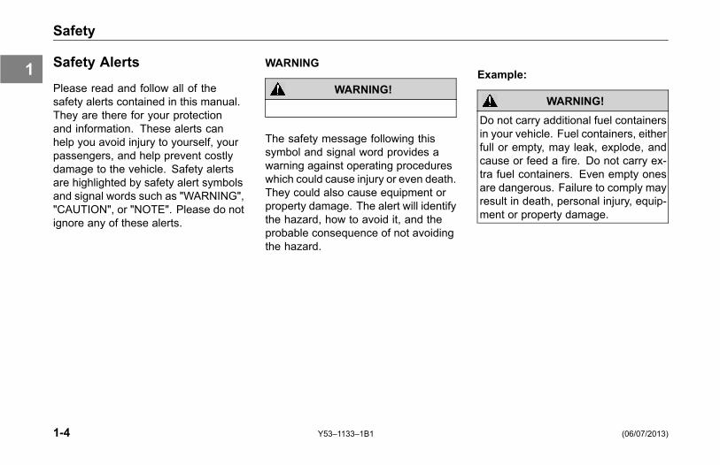
Please read and follow all of thesafety alerts contained in this manual.They are there for your protectionand information. These alerts canhelp you avoid injury to yourself, yourpassengers, and help prevent costlydamage to the vehicle. Safety alertsare highlighted by safety alert symbolsand signal words such as "WARNING","CAUTION", or "NOTE". Please do notignore any of these alerts.
WARNING
WARNING!
The safety message following thissymbol and signal word provides awarning against operating procedureswhich could cause injury or even death.They could also cause equipment orproperty damage. The alert will identifythe hazard, how to avoid it, and theprobable consequence of not avoidingthe hazard.
Example:
WARNING!
Do not carry additional fuel containersin your vehicle. Fuel containers, eitherfull or empty, may leak, explode, andcause or feed a fire. Do not carry ex-tra fuel containers. Even empty onesare dangerous. Failure to comply mayresult in death, personal injury, equip-ment or property damage.
1-4 Y53–1133–1B1 (06/07/2013)
1

Safety
CAUTION
CAUTION
The safety alert following this symboland signal word provides a cautionagainst operating procedures whichcould cause equipment or propertydamage. The alert will identify thehazard, how to avoid it, and theprobable consequence of not avoidingthe hazard.
Example:
CAUTION
Continuing to operate your vehiclewith insufficient oil pressure will causeserious engine damage. Failure tocomply may result in equipment orproperty damage.
NOTE
NOTE
The alert following this symbol andsignal word provides importantinformation that is not safety relatedbut should be followed. The alertwill highlight things that may not beobvious and is useful to your efficientoperation of the vehicle.
Example:
NOTEPumping the accelerator will not assistin starting the engine.
(06/07/2013) Y53–1133–1B1 1-5
1

Safety
IllustrationsGeneral Information
Some of the illustrations throughoutthis manual are generic and will notlook exactly like the engine or partsused in your vehicle.
1-6 Y53–1133–1B1 (06/07/2013)
1

CONTROLS
Aftertreatment System (ATS)Introduction . . . . . . . . . . . . . . . . . . 3-3
Diesel Particulate Filter (DPF) SystemIntroduction . . . . . . . . . . . . . . . . . . 3-4Controlling the Regeneration Process . . . . . . . 3-4Functionality / Notification Information . . . . . . . 3-7DPF Regeneration . . . . . . . . . . . . . . 3-13Stop an Automatic or Parked Regeneration. . . . 3-16Idling in Freezing Temperatures. . . . . . . . . 3-17
Selective Catalytic Reduction (SCR) SystemIntroduction . . . . . . . . . . . . . . . . . 3-18
(06/07/2013) Y53–1133–1B1 3-1
3

Aftertreatment System (ATS)
Aftertreatment System(ATS)
Introduction
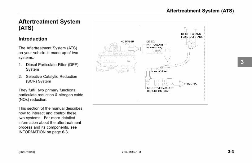
The Aftertreatment System (ATS)on your vehicle is made up of twosystems:
1. Diesel Particulate Filter (DPF)System
2. Selective Catalytic Reduction(SCR) System
They fulfill two primary functions;particulate reduction & nitrogen oxide(NOx) reduction.
This section of the manual describeshow to interact and control thesetwo systems. For more detailedinformation about the aftertreatmentprocess and its components, seeINFORMATION on page 6-3.
(06/07/2013) Y53–1133–1B1 3-3
3

Diesel Particulate Filter (DPF) System
Diesel Particulate Filter(DPF) System
Introduction
The DPF system consists of aHydrocarbon (HC) Doser (may notapply to all engines), a Diesel OxidationCatalyst (DOC), and a DPF. The DPFfilters soot out of the exhaust. Whenactivated, the HC Doser sprays a smallamount of diesel fuel (the HC) intothe exhaust. The catalyst in the DOCreacts with the HC to generate heat.The heat is used to clean (regenerate)the DPF by reducing the trapped sootto ash.
Controlling theRegeneration Process
Your vehicle may be equippedwith either a two or three positionRegeneration Switch, mounted on thedash.
The three-position switch has a Disablemode allowing the driver to controlthe regeneration by overriding theATS when certain operating conditionsare not suitable for regeneration.Refer to Stop an Automatic or ParkedRegeneration on page 3-16.
Vehicles with a two-position switch donot have a Disable mode, only startmode to manually initiate a ParkedRegeneration.
WARNING!
If you operate in environments thatcontain explosive vapors or flammablematerials, look to see if your vehicle’sRegeneration Switch is equipped witha DISABLE function. The DISABLEfunction must be activated prior toentering the above environment(s) toprevent automatic engine regenera-tion from occurring, which could causean explosion or fire. Failure to equipyour vehicle with the proper switch(function) or failing to activate theDISABLE function before entering acombustible environment may causean explosion or fire that could lead todeath, personal injury, equipment orproperty damage.
3-4 Y53–1133–1B1 (06/07/2013)
3

Diesel Particulate Filter (DPF) System
NOTETo obtain a Regeneration Switch with aDISABLE function, contact your near-est authorized PACCAR dealer to ob-tain the proper switch and reprogram-ming of your engine’s ECU.
Three-Position Regeneration Switch
Regeneration Switch
Disable
When DISABLE is pressed, thesystem will not regenerate under anyconditions.
CAUTION
Do not leave the switch in the DIS-ABLE position unless you need to can-cel or stop a regeneration. Runningthe engine with the switch in the DIS-ABLE position will result in increasedsoot levels in the DPF and could even-tually cause the engine to derate.
Center
NOTEDuring normal vehicle driving, theRegeneration Switch must be in theCENTER position.
CENTER is the normal position ofthe switch. Unless you are manuallyinitiating a Parked Regeneration orintentionally stopping a regeneration,the switch should be in this position.Placing the switch in the CENTERposition will allow an Automatic
(06/07/2013) Y53–1133–1B1 3-5
3

Diesel Particulate Filter (DPF) System
Regeneration to occur if conditionsallow.
Manual Regeneration
Depressing the button in the MANUALdirection for at least 4 - 8 seconds willinitiate a Parked Regeneration.
NOTEParked regeneration requires that yourvehicle is stopped with the parkingbrake set. See Parked Regenerationon page 3-13 for details.
Two-Position Regeneration Switch
Two-Position Regeneration Switch
Start
Pressing the button for at least 4- 8 seconds will initiate a ParkedRegeneration.
Aftertreatment System WarningLamps
ATS specific warning lamps andindicator symbols are located on themain gauge cluster.
Diesel ParticulateFilter (DPF) Warning
Lamp Symbol
High Exhaust SystemTemperature (HEST)Warning Lamp
Symbol
Diesel Exhaust Fluid(DEF) Symbol
Malfunction IndicatorLamp (MIL) Symbol
3-6 Y53–1133–1B1 (06/07/2013)
3

Diesel Particulate Filter (DPF) System
Stop Engine Lamp
Illuminates and an audible alarmtone will sound when a major enginesystem problem exists. The vehiclewill be equipped with of the followingindicators:
Functionality / NotificationInformation
The ATS will regenerate the DPF byusing hot exhaust gases normallygenerated by the engine. This typicallyoccurs during highway operation(known as "Passive" Regeneration)and is transparent to the operation ofthe vehicle.
Occasionally, the exhaust gasesare not hot enough for PassiveRegeneration. When this occurs,the ATS will regenerate the DPF byincreasing the exhaust temperature.This is referred to as an "Automatic"Regeneration and is also transparentto vehicle operation. An AutomaticRegeneration event typically lasts30 minutes. During and shortly afterthe event, the exhaust gases fromthe DPF may reach temperatures inexcess of 650° C (1202° F). See theinformation in the following table onprobable causes and recommended
actions related to the warning lampsand indicator symbols of the ATS.
The ATS may not be able to regeneratethe DPF when the vehicle is drivenat extended low speeds or withfrequent starts and stops. In suchcases, warning lamps and indicatorsymbols will alert the operator totake action. The operator should beaware of whether the lamps are onunaccompanied or in combinationwith others. The following table willdescribe each warning lamp(s) andwhat actions are needed from theoperator.
(06/07/2013) Y53–1133–1B1 3-7
3
Diesel Particulate Filter (DPF) System
Notification of High Exhaust System Temperature
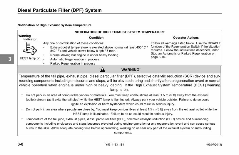
NOTIFICATION OF HIGH EXHAUST SYSTEM TEMPERATUREWarning
Indicator Condition Operator Actions
HEST lamp on
Any one or combination of these conditions:• Exhaust outlet temperature is elevated above normal (at least 450° C /
842° F) and vehicle slows below 8 kph / 5 mph.• Normal driving but engine is under heavy loading.• Automatic Regeneration in process• Parked Regeneration in process
Follow all warnings listed below. Use the DISABLEfunction of the Regeneration Switch if the situationrequires. Follow the instructions described underStop an Automatic or Parked Regeneration onpage 3-16.
WARNING!
Temperature of the tail pipe, exhaust pipe, diesel particular filter (DPF), selective catalytic reduction (SCR) device and sur-rounding components including enclosures and steps, will be elevated during and shortly after a regeneration event or normalvehicle operation when engine is under high or heavy loading. If the High Exhaust System Temperature (HEST) warning
lamp is on:• Do not park in an area of combustible vapors or materials. You must keep combustibles at least 1.5 m (5 ft) away from the exhaust
(outlet) stream (as it exits the tail pipe) while the HEST lamp is illuminated. Always park your vehicle outside. Failure to do so couldignite an explosion or harm bystanders which could result in serious injury.
• Do not park in an area where people are close by. You must keep combustibles at least 1.5 m (5 ft) away from the exhaust outlet while theHEST lamp is illuminated. Failure to do so could result in serious injury.
• Temperature of the tail pipe, exhaust pipes, diesel particular filter (DPF), selective catalytic reduction (SCR) device and surroundingcomponents including enclosures and steps becomes elevated during engine operation or any regeneration event and can cause seriousburns to the skin. Allow adequate cooling time before approaching, working on or near any part of the exhaust system or surrounding
components.
3-8 Y53–1133–1B1 (06/07/2013)
3

Diesel Particulate Filter (DPF) System
Notification Regeneration is Required
NOTIFICATION REGENERATION IS REQUIREDWarningLevel
WarningIndicators Condition Operator Actions
1
DPF lamp on
The soot level in the DPF is abovethe desired level and requiresregeneration.
The DPF requires regeneration soon. Follow the instructionsdescribed under DPF Regeneration on page 3-13.
NOTEIf you ignore the warning lamp and do not initiateregeneration at the soonest, safest possible time, theDPF will become increasingly clogged with soot andcan lead to severe engine derate.
2
DPF lamp flashes
The soot level in the DPF continuesto stay above the desired level andrequires regeneration.
Regenerate the DPF as soon as safely possible. Follow theinstructions described under DPF Regeneration on page 3-13.
CAUTION
If you do not initiate regeneration after the DPFwarn-ing lamp begins to flash, you only have a short timebefore the Check Engine lamp will illuminate andthe engine will go into a protection mode and der-ate power.
(06/07/2013) Y53–1133–1B1 3-9
3

Diesel Particulate Filter (DPF) System
NOTIFICATION REGENERATION IS REQUIREDWarningLevel
WarningIndicators Condition Operator Actions
3
DPF lamp flashes
Check Engine lamp on
The soot level in the DPF continuesto stay above the desired level andrequires regeneration.The engine power will derate.
Regenerate the DPF immediately. Follow the instructionsdescribed under DPF Regeneration on page 3-13 for PACCARMX engines, Parked Regeneration on page 3-13 for PACCARPX and Cummins engines.
CAUTION
If you do not initiate regeneration after the DPFwarn-ing lamp begins to flash and the Check Engine lampis on, you only have a short time before the Stop En-gine lamp will illuminate and the engine power willderate severely. No regeneration will be allowed atthe next stage.
NOTEUnder some conditions after prolonged stationaryidling, a Parked Regeneration may be required with-out a Level 1 or Level 2 warning.
3-10 Y53–1133–1B1 (06/07/2013)
3

Diesel Particulate Filter (DPF) System
NOTIFICATION REGENERATION IS REQUIREDWarningLevel
WarningIndicators Condition Operator Actions
4
DPF lamp flashes (MX engineonly)
Check Engine lamp on (MXengine only)
Stop Engine lamp on
Dash chime will sound
The soot level in the DPF is now at fullcapacity.Engine power derates (decrease ratedepends on engine make)
NOTEThe engine derate sequenceis engine specific; therefore, tolearn how this system works onyour vehicle, refer to the EngineManufacturer's Operation andMaintenance Manual suppliedwith your vehicle.
At this point, you CANNOT regenerate the DPF. Tow yourvehicle to an Authorized PACCAR Dealer to have the DPFremoved. They will either have to clean it or replace it.
WARNING!
If the Stop Engine warning lamp illuminates, it meansyou have a serious engine system problem. Thisshould be considered an emergency. You shouldstop the vehicle as safely as possible and turn OFFthe ignition. The vehicle must be serviced and theproblem corrected before driving again. Failure tocomply may result in death, personal injury, equip-ment or property damage.
(06/07/2013) Y53–1133–1B1 3-11
3

Diesel Particulate Filter (DPF) System
Quick Reference Guide
3-12 Y53–1133–1B1 (06/07/2013)
3

Diesel Particulate Filter (DPF) System
DPF Regeneration
Carefully read the following instructionsto regenerate the DPF. If you have anyproblems or difficulties contact yournearest authorized PACCAR dealer forassistance.
The ATS requires conditions typicallyfound in highway driving to regeneratethe DPF. If the DPF warning lamp isilluminated, the easiest option is toassist the ATS by proceeding to thenearest highway.
• Select a highway that has a postedlegal speed of more than 56 kph(35 mph).
• Drive your vehicle until the DPFlamp goes off. This may take 30 -45 minutes of speeds greater than32 kph (20 mph).
If your operation or planned route inthe immediate future limits your abilityto reach highway speeds, proceed
to the next section titled ParkedRegeneration.
Parked Regeneration
In very limited applications oroperations the DPF must beregenerated by initiating a ParkedRegeneration. Follow these sevensteps to initiate a Parked Regeneration:
1. Pull the vehicle over to a safelocation.
2. Ensure no one is in the immediatevicinity of the tail pipe.
3. Maintain a minimum of 1.5 m (5 ft)of clearance to any combustiblematerials from the edge and topof the vehicle.
(06/07/2013) Y53–1133–1B1 3-13
3

Diesel Particulate Filter (DPF) System
WARNING!
Parking the vehicle too close to anycombustible materials or vapors maystart a fire, ignite an explosion or burnsomeone standing close by. Beforepushing the Regeneration Switch onthe dash, walk around your vehicleand ensure you have at least 1.5 m (5ft) clearance from the sides and top ofyour vehicle to any combustibles. En-sure no one is in the immediate vicinityof the tail pipe. Failure to comply couldignite a fire or cause an explosion, re-sulting in death, personal injury, equip-ment or property damage.
WARNING!
Never initiate a regeneration in aclosed building or enclosure. Alwayspark your vehicle outside and ensureno one is in the immediate vicinity.Failure to comply could ignite a fire orcause an explosion, resulting in death,personal injury, equipment or propertydamage.
NOTETypical operation areas or materialsthat can contain explosive vapors,flammable materials or people in closeproximity of the vehicle are:
• Fuel depots
• Grain elevators
• Dry grass, leaves or trees
• Transfer refuse stations/dumps
• Parking lots
• Load/unload terminals
NOTEWhile the list above may appear com-prehensive, it is your responsibility totake the necessary precautions and beaware of your surroundings and en-sure that no combustibles (materials orvapors) or bystanders are close by be-fore initiating a regeneration.
3-14 Y53–1133–1B1 (06/07/2013)
3
Diesel Particulate Filter (DPF) System
4. Verify that the following conditionsare met before proceeding. AParked Regeneration will notinitiate if any of these conditionsare not met:
° Parking brake is applied / set
° Engine is at low idle
° DPF warning lamp isilluminated or flashing
° Coolant is at operatingtemperature
° No throttle
° PTO is disengaged
° Transmission is in neutral
° Cruise control switch is off
5. Get out and walk all around vehicleto ensure that the vehicle is atleast 1.5 m (5 ft) away from all
combustible materials and no oneis in the immediate vicinity.
6. Climb back into the vehicle.
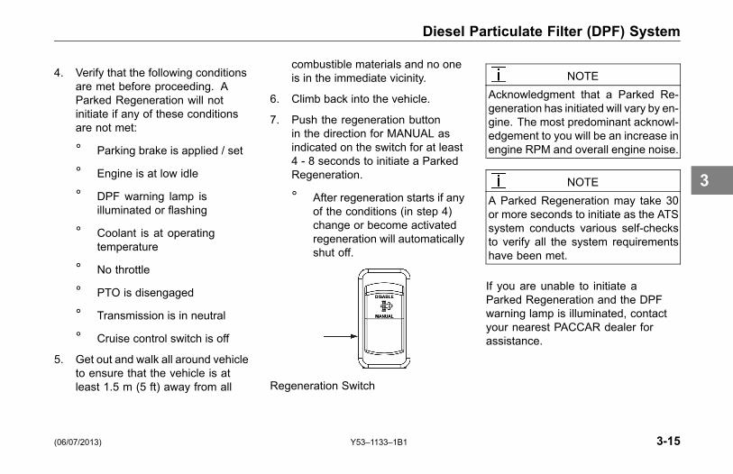
7. Push the regeneration buttonin the direction for MANUAL asindicated on the switch for at least4 - 8 seconds to initiate a ParkedRegeneration.
° After regeneration starts if anyof the conditions (in step 4)change or become activatedregeneration will automaticallyshut off.
Regeneration Switch
NOTEAcknowledgment that a Parked Re-generation has initiated will vary by en-gine. The most predominant acknowl-edgement to you will be an increase inengine RPM and overall engine noise.
NOTEA Parked Regeneration may take 30or more seconds to initiate as the ATSsystem conducts various self-checksto verify all the system requirementshave been met.
If you are unable to initiate aParked Regeneration and the DPFwarning lamp is illuminated, contactyour nearest PACCAR dealer forassistance.
(06/07/2013) Y53–1133–1B1 3-15
3

Diesel Particulate Filter (DPF) System
Stop an Automatic or ParkedRegeneration
NOTEThe information in this section only ap-plies to vehicles equipped with a three-position Engine Regeneration Switch.
If an Automatic or Parked Regenerationis in process and you want theregeneration to stop, OR you want toprevent a regeneration from occurring,your vehicle is equipped with a switchthat can stop an Automatic or ParkedRegeneration. Since AutomaticRegenerations can occur at any time,you must depress the DISABLE portionof the Regeneration Switch ANYTIMEyou plan to drive your vehicle intoa building, enclosure or area wherethe activation of a regeneration is notallowed. If the regeneration does notstop, turn the vehicle ignition OFF.
WARNING!
Never allow an Automatic Regenera-tion to automatically occur while insidea building such as a service bay, shopor building of any kind. Anytime youare parking your vehicle inside a build-ing or enclosure, ALWAYS press theRegeneration (DISABLE) Switch priorto entering the building. Failure tocomply could ignite a fire or cause anexplosion, resulting in death, personalinjury, equipment or property damage.
WARNING!
Never initiate a Parked Regenerationin a closed building or enclosure. Al-ways park your vehicle outside. Fail-ure to comply could ignite a fire orcause an explosion, resulting in death,personal injury, equipment or propertydamage.
WARNING!
If you operate in environments thatcontain explosive vapors or flammablematerials, look to see if your vehicle’sRegeneration Switch is equipped witha DISABLE function. The DISABLEfunction must be activated prior toentering the above environment(s) toprevent automatic engine regenera-tion from occurring, which could causean explosion or fire. Failure to equipyour vehicle with the proper switch(function) or failing to activate theDISABLE function before entering acombustible environment may causean explosion or fire that could lead todeath, personal injury, equipment orproperty damage.
3-16 Y53–1133–1B1 (06/07/2013)
3

Diesel Particulate Filter (DPF) System
NOTETo obtain a Regeneration Switch witha DISABLE function, contact an au-thorized PACCAR dealer to obtain theproper switch and reprogramming ofyour engine’s ECU.
Idling in FreezingTemperatures
Idling the engine for 3 or more hoursin freezing temperatures causes thebuild up of soot and moisture in theDPF. Extra heat is required to oxidizethe soot and moisture by using thefollowing methods:
• DPF Regeneration:If the DPF Lamp turns on, followthe instructions described underDPF Regeneration on page 3-13.
NOTEIf you ignore the warning lamp and donot initiate regeneration at the soon-est, safest possible time, the DPF willbecome increasingly cloggedwith sootand can lead to engine shutdown.
• PACCAR PX-7 and PX-9 Enginesand Cummins ISL Engine:Regardless if the DPF lamp ison or off, the engine speed willautomatically increase to 1000to 1100 RPM and remain at thisspeed for 10 minutes to performan automated DPF cleaning.If necessary, the RPMs canbe lowered by depressing thethrottle, clutch, or brake pedal.If the engine continues to idle,the aftertreatment system will tryagain to raise the idle speed untilthe aftertreatment temperaturesare suitable.
(06/07/2013) Y53–1133–1B1 3-17
3

Selective Catalytic Reduction (SCR) System
Selective CatalyticReduction (SCR) System
Introduction
The SCR system consists of a DieselExhaust Fluid (DEF) Doser and a SCRCatalyst. The DEF Doser sprays asmall amount of DEF into the exhaust.The SCR Catalyst reacts with the DEFto break down the Nitrogen Oxides(NOx) in the exhaust into nitrogen andwater vapor.
Diesel Exhaust Fluid (DEF) Gauge
1 DEF Symbol
2 DEF WarningLamp
DEF is consumable and needs to bereplenished, so monitor the DEF levelgauge as you would the fuel levelgauge.
The DEF warning lamp will illuminatefor the following 3 reasons:
1. DEF Level Warning: To warn youto refill the DEF tank. The warninglamp will turn on when the gaugeneedle is near or in the red zone.There are 4 stages to this warning.
CAUTION
If the DEF warning lamp turns on dueto the DEF level, refill the DEF tank.Failure to refill may cause the engineto derate and limit vehicle speed.
2. DEF Quality: The enginedetects that DEF quality is belowacceptable levels. The gaugeneedle is in the upper region,indicating there is fluid, but thequality is poor. There are 3 stagesto these warnings.
3-18 Y53–1133–1B1 (06/07/2013)
3

Selective Catalytic Reduction (SCR) System
CAUTION
If the DEF warning lamp turns on dueto DEF Quality, see Contamination/In-correct Fluid for corrective action. Fail-ure to correct may cause the engine toderate and limit vehicle speed.
3. SCR System Tampering: To warnyou when the engine system
detects failures that may be theresult of tampering with the SCRsystem. The gauge needle isin the upper region, indicatingthere is fluid, but system failure isdetected. There are 3 stages tothis warning.
CAUTION
If the DEF warning lamp turns on dueto System Tampering, see your autho-rized PACCAR dealer to have this re-paired. Failure to repair the systemmay cause the engine to derate andlimit vehicle speed.
System Status Non-Emergency Vehicles Emergency VehiclesDEF Level Warning See table on page 3-20. See table on page 3-26.DEF Quality See table on page 3-22. See table on page 3-27.SCR System Tampering See table on page 3-24. See table on page 3-29.
(06/07/2013) Y53–1133–1B1 3-19
3

Selective Catalytic Reduction (SCR) System
DEF Level Warning – Non-Emergency Vehicles
DEF LEVEL WARNING – NON-EMERGENCY VEHICLES
WarningLevel Warnings Indicators Condition Effect on Engine
0 None DEF Level sufficient None
1DEF Warning Lamp on
DEF Level fallenbelow initial warning None
2DEF Warning Lamp
flashing
DEF Level fallenbelow initial warning None
3DEF Warning Lamp
flashingCheck Engine Lamp
on
DEF Level fallenbelow initial warning
Engine powerderated 25%
4DEF Warning Lamp
flashingCheck Engine Lamp
on
DEF Level empty Engine powerderated 40%
3-20 Y53–1133–1B1 (06/07/2013)
3

Selective Catalytic Reduction (SCR) System
DEF LEVEL WARNING – NON-EMERGENCY VEHICLES
WarningLevel Warnings Indicators Condition Effect on Engine
FinalDEF Warning Lamp
flashingCheck Engine Lamp
onMIL may be on Stop Engine Lamp
may be on
Engine has beenshut down, idled for1-hour or a fuel re-fill
has occurred
Engine powerderated and/orvehicle speedsignificantlylimited
NOTEThe Malfunction Indicator Lamp (MIL) will illuminate if the OBD (Onboard Diagnostics) system detects a possibleemissions system failure.
(06/07/2013) Y53–1133–1B1 3-21
3
Selective Catalytic Reduction (SCR) System
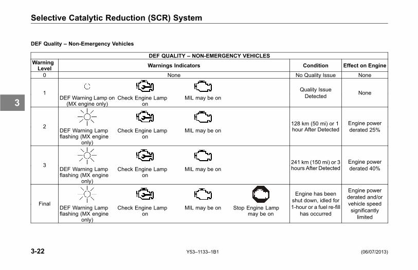
DEF Quality – Non-Emergency Vehicles
DEF QUALITY – NON-EMERGENCY VEHICLESWarningLevel Warnings Indicators Condition Effect on Engine
0 None No Quality Issue None
1DEF Warning Lamp on
(MX engine only)Check Engine Lamp
onMIL may be on
Quality IssueDetected None
2DEF Warning Lampflashing (MX engine
only)
Check Engine Lampon
MIL may be on128 km (50 mi) or 1hour After Detected
Engine powerderated 25%
3DEF Warning Lampflashing (MX engine
only)
Check Engine Lampon
MIL may be on241 km (150 mi) or 3hours After Detected
Engine powerderated 40%
FinalDEF Warning Lampflashing (MX engine
only)
Check Engine Lampon
MIL may be on Stop Engine Lampmay be on
Engine has beenshut down, idled for1-hour or a fuel re-fill
has occurred
Engine powerderated and/orvehicle speedsignificantlylimited
3-22 Y53–1133–1B1 (06/07/2013)
3
Selective Catalytic Reduction (SCR) System
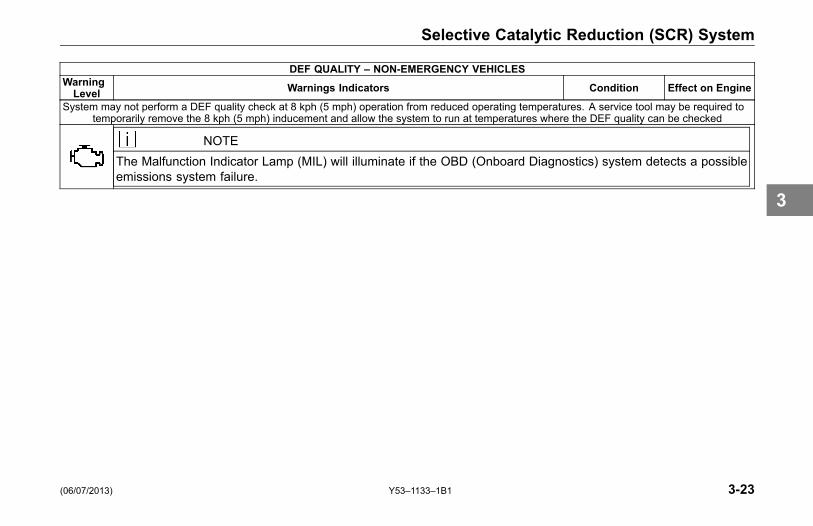
DEF QUALITY – NON-EMERGENCY VEHICLESWarningLevel Warnings Indicators Condition Effect on Engine
System may not perform a DEF quality check at 8 kph (5 mph) operation from reduced operating temperatures. A service tool may be required totemporarily remove the 8 kph (5 mph) inducement and allow the system to run at temperatures where the DEF quality can be checked
NOTEThe Malfunction Indicator Lamp (MIL) will illuminate if the OBD (Onboard Diagnostics) system detects a possibleemissions system failure.
(06/07/2013) Y53–1133–1B1 3-23
3

Selective Catalytic Reduction (SCR) System
SCR Component Failure – Non-Emergency Vehicles
SCR COMPONENT FAILURE – NON-EMERGENCY VEHICLESWarningLevel Warnings Indicators Condition Effect on Engine
0 None No Issue None
1DEF Warning Lamp on
(MX engine only)Check Engine Lamp
onMIL may be on
Failure Detected None
2DEF Warning Lampflashing (MX engine
only)
Check Engine Lampon
MIL may be on128 km (50 mi) or 1hour After Detected
Engine powerderated 25%
3DEF Warning Lampflashing (MX engine
only)
Check Engine Lampon
MIL may be on322 km (200 mi) or 4hours After Detected
Engine powerderated 40%
3-24 Y53–1133–1B1 (06/07/2013)
3

Selective Catalytic Reduction (SCR) System
SCR COMPONENT FAILURE – NON-EMERGENCY VEHICLESWarningLevel Warnings Indicators Condition Effect on Engine
FinalDEF Warning Lampflashing (MX engine
only)
Check Engine Lampon
MIL may be on Stop Engine Lampmay be on
Engine has beenshut down, idled for1-hour or a fuel re-fill
has occurred
Engine powerderated and/orvehicle speed
reduced to 8 kph(5 mph)
NOTEThe Malfunction Indicator Lamp (MIL) will illuminate if the OBD (Onboard Diagnostics) system detects a possibleemissions system failure.
(06/07/2013) Y53–1133–1B1 3-25
3
Selective Catalytic Reduction (SCR) System
DEF Level Warning – Emergency Vehicles
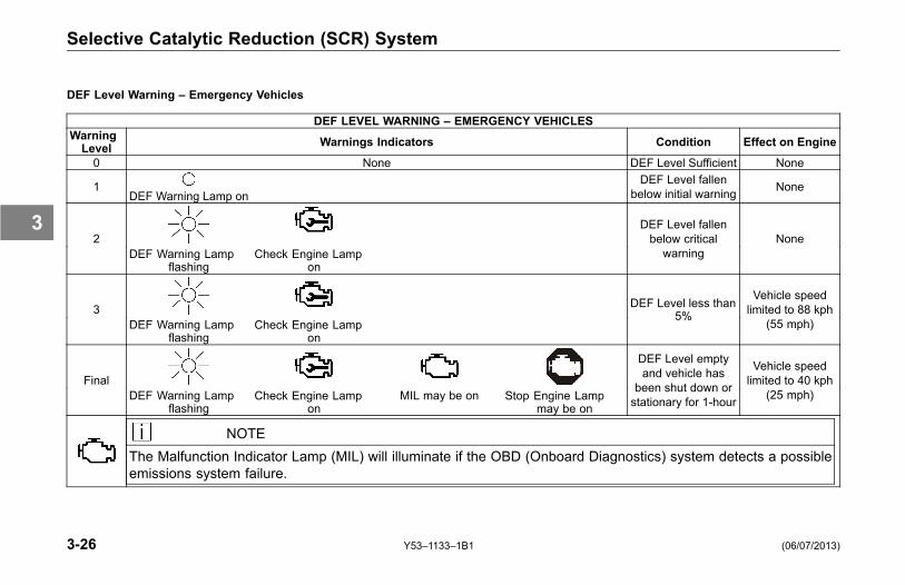
DEF LEVEL WARNING – EMERGENCY VEHICLESWarningLevel Warnings Indicators Condition Effect on Engine
0 None DEF Level Sufficient None
1DEF Warning Lamp on
DEF Level fallenbelow initial warning None
2DEF Warning Lamp
flashingCheck Engine Lamp
on
DEF Level fallenbelow criticalwarning
None
3DEF Warning Lamp
flashingCheck Engine Lamp
on
DEF Level less than5%
Vehicle speedlimited to 88 kph
(55 mph)
FinalDEF Warning Lamp
flashingCheck Engine Lamp
onMIL may be on Stop Engine Lamp
may be on
DEF Level emptyand vehicle has
been shut down orstationary for 1-hour
Vehicle speedlimited to 40 kph
(25 mph)
NOTEThe Malfunction Indicator Lamp (MIL) will illuminate if the OBD (Onboard Diagnostics) system detects a possibleemissions system failure.
3-26 Y53–1133–1B1 (06/07/2013)
3
Selective Catalytic Reduction (SCR) System
DEF Quality – Emergency Vehicles
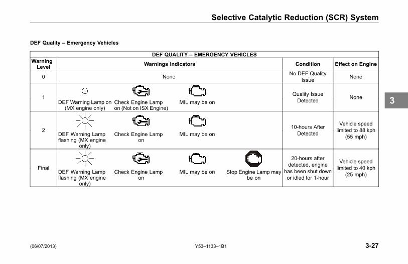
DEF QUALITY – EMERGENCY VEHICLESWarningLevel Warnings Indicators Condition Effect on Engine
0 None No DEF QualityIssue None
1DEF Warning Lamp on
(MX engine only)Check Engine Lampon (Not on ISX Engine)
MIL may be onQuality IssueDetected None
2DEF Warning Lampflashing (MX engine
only)
Check Engine Lampon
MIL may be on10-hours After
Detected
Vehicle speedlimited to 88 kph
(55 mph)
FinalDEF Warning Lampflashing (MX engine
only)
Check Engine Lampon
MIL may be on Stop Engine Lamp maybe on
20-hours afterdetected, engine
has been shut downor idled for 1-hour
Vehicle speedlimited to 40 kph
(25 mph)
(06/07/2013) Y53–1133–1B1 3-27
3

Selective Catalytic Reduction (SCR) System
DEF QUALITY – EMERGENCY VEHICLESWarningLevel Warnings Indicators Condition Effect on Engine
System may not perform a DEF quality check at 8 kph (5 mph) operation from reduced operating temperatures. A service tool may be required totemporarily remove the 8 kph (5 mph) inducement and allow the system to run at temperatures where the DEF quality can be checked
NOTEThe Malfunction Indicator Lamp (MIL) will illuminate if the OBD (Onboard Diagnostics) system detects a possibleemissions system failure.
3-28 Y53–1133–1B1 (06/07/2013)
3

Selective Catalytic Reduction (SCR) System
SCR Component Failure – Emergency Vehicles
SCR COMPONENT FAILURE – EMERGENCY VEHICLESWarningLevel Warnings Indicators Condition Effect on Engine
0 None No Issue None
1DEF Warning Lamp on
(MX engine only)Check Engine Lamp
onMIL may be on
Failure Detected None
2DEF Warning Lampflashing (MX engine
only)
Check Engine Lampon
MIL may be on10-hours After
Detected
Vehicle speedlimited to 88 kph
(55 mph)
FinalDEF Warning Lampflashing (MX engine
only)
Check Engine Lampon
MIL may be on Stop Engine Lampmay be on
40-hours afterdetected, engine
has been shut downor idled for 1-hour
Vehicle speedlimited to 40 kph
(25 mph)
NOTEThe Malfunction Indicator Lamp (MIL) will illuminate if the OBD (Onboard Diagnostics) system detects a possibleemissions system failure.
(06/07/2013) Y53–1133–1B1 3-29
3


MAINTENANCE
Diesel Exhaust Fluid (DEF) Tank Straps . . . . . . 5-3
(06/07/2013) Y53–1133–1B1 5-1
5


Selective Catalytic Reduction (SCR) System
Diesel Exhaust Fluid (DEF)Tank Straps
During normal operation of the truck,the DEF tank straps may relax. Inspectthe spring on top of the strap. Ifmore than ½” (12.7mm) of the springis exposed, the bolt will need to bere-torqued between 70 – 80 in-lbs. (7.9– 9 Nm). This distance is measuredfrom the washer at the end of thespring to the edge of the tube at thetop of the straps.
See Engine Operator's Manual for filtermaintenance interval
(06/07/2013) Y53–1133–1B1 5-3
5

INFORMATION
InformationIntroduction . . . . . . . . . . . . . . . . . . 6-3Tampering with Aftertreatment System . . . . . . . 6-4
Diesel Particulate Filter (DPF) SystemOverview . . . . . . . . . . . . . . . . . . . 6-5
Selective Catalytic Reduction (SCR) SystemOverview . . . . . . . . . . . . . . . . . . . 6-7Diesel Exhaust Fluid (DEF) Recommendations andSpecifications . . . . . . . . . . . . . . . . 6-8
Storage . . . . . . . . . . . . . . . . . . . 6-10Handling . . . . . . . . . . . . . . . . . . . 6-11Disposal . . . . . . . . . . . . . . . . . . . 6-11Contamination/Incorrect Fluid. . . . . . . . . . 6-12Freezing . . . . . . . . . . . . . . . . . . . 6-12
(06/07/2013) Y53–1133–1B1 6-1
6


Information
Information
Introduction
The Aftertreatment System (ATS)on your vehicle is made up of twosystems:
1. Diesel Particulate Filter (DPF)System
2. Selective Catalytic Reduction(SCR) System
They fulfill two primary functions:particulate reduction & nitrogen oxide(NOx) reduction.
This section of the manual providesmore detailed information aboutthe aftertreatment process and itscomponents.
(06/07/2013) Y53–1133–1B1 6-3
6
Information
Tampering withAftertreatment System
The aftertreatment system for yourvehicle as installed from the factorywas specifically designed to meet theemissions requirements of the USEnvironmental Protection Agency andCalifornia Air Resources Board. Anychanges of component locations ormodifications of any aftertreatmentsystem components may reduce theemission effectiveness and you maybe subject to fines under the UnitedStates Clean Air Act.
6-4 Y53–1133–1B1 (06/07/2013)
6

Diesel Particulate Filter (DPF) System
Diesel Particulate Filter(DPF) System
Overview
The DPF system consists of aHydrocarbon (HC) Doser (maynot apply to all engines), a DieselOxidation Catalyst (DOC), and a DPF.
The components of the DPF systemperform the following functions:
• The ATS inlet and outlet adaptthe vehicle exhaust piping to theATS, and also provide a mountinglocation for the aftertreatment gastemperature sensors.
• The DPF differential pressuresensor measures the restrictionacross the DPF.
• The DPF filters soot out of theexhaust.
• When activated, the HC Dosersprays a small amount of dieselfuel (the HC) into the exhaust. Thecatalyst in the DOC reacts withthe HC to generate heat. The heatis used to clean (regenerate) theDPF by reducing the trapped sootto ash.
• Soot is composed of the partiallyburned particles of fuel that occurduring normal engine operation(black smoke).
• Over time, both soot and ashaccumulate in the DPF and mustbe removed. Soot is removed bya process called regeneration.Ash is removed by removing theDPF and cleaning it at specifiedintervals.
• A vehicle with a DPF has up totwo additional indicator lamps onthe dashboard. The two additionallamps, along with the check
engine lamp, alert the operator ofthe status of the DPF.
(06/07/2013) Y53–1133–1B1 6-5
6

Diesel Particulate Filter (DPF) System
CAUTIONDo not submerge or allow water to en-ter the DPF assembly. Components ofthe assembly can be damaged and ef-fect the performance of the aftertreat-ment system. Failure to comply mayresult in equipment or property dam-age.
NOTERefer to your engine manufacturer’sOperator’s Manual for diesel particu-late filter (DPF) maintenance informa-tion.
NOTERefer to your vehicle or engine man-ufacturer’s Operator’s Manual for ad-ditional information on the engine indi-cator lamps.
NOTEUltra low sulfur diesel (ULSD) fuel isrequired for engines equipped with anaftertreatment diesel particulate filter.If ULSD is not used, the engine maynot meet emissions regulations, andthe DPF or aftertreatment Diesel Ox-idation Catalyst (DOC) can be dam-aged.
6-6 Y53–1133–1B1 (06/07/2013)
6

Selective Catalytic Reduction (SCR) System
Selective CatalyticReduction (SCR) System
Overview
The SCR system is composed ofseveral main components:
1. Diesel Exhaust Fluid (DEF)Controller
2. DEF Dosing Unit (DEF Module)
3. DEF Dosing Valve
4. SCR Catalyst
NOTEIt is unlawful to tamper with, mod-ify, or remove any component of theSCR system. It is also unlawful touse DEF that does not meet the spec-ifications provided or to operate thevehicle/equipment with no DEF.
DEF is required for an engine equippedwith a SCR system. DEF is a fluid that
is sprayed into the exhaust gas prior tothe SCR catalyst. The DEF vaporizesand decomposes to form carbondioxide and ammonia. The ammoniareacts with the NOx emissions over theaftertreatment SCR catalyst to formnitrogen and water.
DEF:
• may have a slight ammonia smell
• is colorless
• is non-toxic and non-polluting
• is non-flammable
(06/07/2013) Y53–1133–1B1 6-7
6

Selective Catalytic Reduction (SCR) System
Diesel Exhaust Fluid (DEF)Recommendations andSpecifications
WARNING!
It is unlawful to tamper with or removeany component of the aftertreatmentsystem. It is also unlawful to use aDiesel Exhaust Fluid (DEF) that doesnot meet the specifications provided orto operate the vehicle/equipment with-out Diesel Exhaust Fluid (DEF).
WARNING!
Diesel Exhaust Fluid (DEF) containsurea. Do not get the substance in youreyes. In case of contact, immediatelyflush eyes with large amounts of wa-ter for a minimum of 15 minutes. Donot swallow internally. In the event thediesel exhaust fluid is ingested, con-tact a physician immediately. Refer-ence the Materials Safety Data Sheet(MSDS) for additional information.
CAUTIONNever attempt to create Diesel Ex-haust Fluid (DEF) by mixing agricul-tural grade urea with water. Agricul-tural grade urea does not meet thenecessary specifications required andthe aftertreatment system may bedamaged.
CAUTION
PACCAR Inc requires the use of DEFmeeting ISO 22241-1 (DIN 70070)specifications. There is NO accept-able substitute. Failure to use thecorrect DEF may cause engine dam-age and/or void the warranty.
6-8 Y53–1133–1B1 (06/07/2013)
6

Selective Catalytic Reduction (SCR) System
NOTESome locationsmay reference the DIN70070 standard. DEF specificationlimits of this standard are identical toISO 22241-1.
PACCAR Inc is not responsible forfailures or damage resulting fromwhat PACCAR Inc determines to beabuse or neglect, including but notlimited to: operation without correctlyspecified DEF; lack of maintenanceof aftertreatment; improper storage,or shutdown practices; unauthorizedmodifications of the engine andaftertreatment. PACCAR is also notresponsible for failures caused byincorrect DEF or by water, dirt or othercontaminants in the DEF. Refer toyour engine and vehicle operator'smanuals for maintenance, storage,and shutdown information.
For engines using SCR operating inthe United States and Canada, it isrecommended that the DEF used becertified by the American PetroleumInstitute (API).
NOTETo ensure the correct DEF is used,PACCAR Inc recommends the use ofTRP® CleanBlue Diesel Exhaust Fluidwhich is available in different quantityoptions from small to bulk containers.
• DEF is readily available at truckstops and at all PACCAR Enginedealers. For assistance locatingDEF, contact your local PACCARauthorized repair location.
• If your vehicle is out of DEFand you are unable to locate asource to purchase DEF, pleasecontact the vehicle OEM customercare center at the telephonenumber provided in the vehicleoperator’s manual. The vehicleOEM customer care center will beable to contact the nearest dealerlocation to you and arrange for anemergency shipment of DEF toyour location 24 hours a day.
(06/07/2013) Y53–1133–1B1 6-9
6
Selective Catalytic Reduction (SCR) System
The following are other commonnames used for Diesel Exhaust Fluid(DEF):
• AUS 32 (Aqueous Urea Solution32)
• AdBlue
• NOx Reduction Agent
• Catalyst Solution
Regardless of what the DEF is called,the DEF must meet the ISO 22241-1(DIN 70070) specifications.
Storage
NOTEThe following information is for refer-ence and is to be used as a guide-line only. There are many factors thatdetermine Diesel Exhaust Fluid (DEF)shelf life, with temperature and dura-tion being two of the major determiningcontributors. If in doubt, replace thefluid with known quality DEF. DEF hasa limited shelf life, both in the vehicle'sdiesel exhaust fluid tank and in stor-age/bulk/transportation containers.
The following conditions are ideal formaintaining DEF quality and shelf lifeduring prolonged transportation andstorage:
• Storage temperature between-5°C and 25°C (23°F and 77°F)
• Storage in sealed containers toavoid contamination
• Avoidance of direct sunlight
In these conditions, Diesel ExhaustFluid (DEF) has a minimum expectedshelf life of 18 months. If stored athigher temperatures for extendedperiods of time, the shelf life willbe reduced by approximately 6months for every 5°C (9°F) abovethe highest storage temperaturelisted above. Long term storage in avehicle (in excess of 6 months) is notrecommended.
NOTETo assist in preventing DEF from de-teriorating when stored in the vehicle'sDEF tank, locate and plug the tank'sventing to seal the tank exposure tothe atmosphere.
6-10 Y53–1133–1B1 (06/07/2013)
6

Selective Catalytic Reduction (SCR) System
Handling
CAUTION
If Diesel Exhaust Fluid (DEF) is spilledon metal surfaces (for example thesteps, fuel tanks or grab handles) rinseand clean immediately with water.Failure to do so may leave permanentcorrosive stains on the metal surfaceswhich can not be removed.
• Make sure to only use approvedcontainers to transport andstore DEF. Containers made ofpolyethylene and polypropyleneare recommended.
• If DEF is spilled, rinse and cleanimmediately with water.
• Avoid prolonged contact with skin.In case of contact, wash withimmediately with soap and water.If not washed immediately, a whitefilm will be left when the DEF dries
that can be more difficult to washoff.
NOTESpilled DEF, if left to dry or wiped awaywith a cloth only, will leave a whiteresidue. Failure to clean the spilledDEF may result in an incorrectly diag-nosed leak of the DEF Dosing system.
Before using containers, funnels,etc. that will be used to dispense,handle or store DEF, make sureto wash thoroughly to remove anycontaminants and then rinse withdistilled water.
NOTEDo not use tap water to rinse compo-nents that will be used to deliver dieselexhaust fluid. Tap water will contami-nate the DEF. If distilled water is notavailable, rinse with tap water and thenrinse with DEF.
Disposal
If disposing Diesel Exhaust Fluid(DEF), always check with the localauthority regulations on properdisposal process and requirements.
(06/07/2013) Y53–1133–1B1 6-11
6
Selective Catalytic Reduction (SCR) System
Contamination/IncorrectFluid
CAUTION
Never add water or any other fluidbesides what is specified to the DEFtank. The aftertreatment system maybe damaged.
In the event that the incorrect fluidis added to the Diesel Exhaust Fluidtank, such as, but not limited to:
• Water
• Diesel Fuel
• Hydraulic Fluid
• Coolant
• Windshield Washer Fluid
Contact a local PACCAR AuthorizedRepair location to determine theappropriate repair direction. If onlywater has been added to the DEF tank,
drain the DEF tank, flush with distilledwater and refill with new and/or knowngood DEF.
Freezing
CAUTION
The Diesel Exhaust Fluid (DEF) sys-tem purges to prevent damage fromfreezing. If your vehicle is equippedwith battery disconnect switches, doNOT disconnect battery power withintwo minutes of switching the ignitionkey off. Failure to comply may resultin vehicle or property damage.
CAUTION
Do NOT add any chemicals/additivesto the Diesel Exhaust Fluid (DEF) inan effort to prevent freezing. If chem-icals/additives are added to the DEF,the aftertreatment system may bedamaged.
DEF will freeze around -12°C (11°F).The DEF system on the vehicle isdesigned to accommodate this anddoes not require any intervention.
6-12 Y53–1133–1B1 (06/07/2013)
6

Index
Index
AAbout this Manual. . . . . . . . . . . . . . . . . . . .1-3Aftertreatment Informationaftertreatment inlet and outlet . . . .6-5alternate DEF names . . . . . . . . . . . 6-10contamination or incorrect fluid 6-12DEF controller . . . . . . . . . . . . . . . . . . . . .6-7DEF dosing unit . . . . . . . . . . . . . . . . . . .6-7DEF dosing valve . . . . . . . . . . . . . . . . .6-7DEF Module . . . . . . . . . . . . . . . . . . . . . . .6-7diesel oxidation catalyst . . . . . . . . . .6-5diesel particulate filter. . . . . . . . . . . . .6-5diesel particulate filter (DPF)
differential pressure sensor .6-5freezing. . . . . . . . . . . . . . . . . . . . . . . . . . . 6-12indicator lamps . . . . . . . . . . . . . . . . . . . .6-5recommendations and
specifications . . . . . . . . . . . . . . . . .6-8regeneration . . . . . . . . . . . . . . . . . . . . . . .6-5SCR catalyst . . . . . . . . . . . . . . . . . . . . . . .6-7
selective catalytic reduction(SCR) . . . . . . . . . . . . . . . . . . . . . . . . .6-7
soot . . . . . . . . . . . . . . . . . . . . . . . . . . . . . . . . .6-5storage, handling and disposal. . .6-8ultra low sulfur diesel (ULSD)
fuel . . . . . . . . . . . . . . . . . . . . . . . . . . . .6-6Aftertreatment System (ATS) . . . . . . .6-3diesel particulate filter (DPF)
system .. . . . . . . . . . . . . . . . . 3-4–6-5Aftertreatment System DescriptionDPF regeneration . . . . . . . . . . . . . . . 3-13functionality / notification
information. . . . . . . . . . . . . . . . . . . .3-7high exhaust system
temperature. . . . . . . . . . . . . . . . . . .3-8notification regeneration is
required . . . . . . . . . . . . . . . . . . . . . . .3-9parked regeneration. . . . . . . . . . . . . 3-13regeneration (MANUAL) switch 3-15stopping an automatic or parked
regeneration . . . . . . . . . . . . . . . . 3-16
Aftertreatment System Tampering. .6-4Aftertreatment System Warning
Lamps . . . . . . . . . . . . . . . . . . . . . . . . . . .3-6diesel particulate filter (DPF) warning
lamp symbol . . . . . . . . . . . . . . . . . .3-6high exhaust system temperature
(HEST) warning lampsymbol . . . . . . . . . . . . . . . . . . . . . . . .3-6
Automatic Regeneration. . . . . . .3-4–3-5,3-7, 3-16
CCaution. . . . . . . . . . . . . . . . . . . . . . . . . . . . . . . .1-5Cleaning . . . . . . . . . . . . . . . . . . . . . . . . 3-4–6-5Consumer information . . . . . . . . . . . . . . .6-3Contamination/Incorrect Fluid . . . . 6-12Controlling the Regeneration
Process . . . . . . . . . . . . . . . . . . . . . . . . . .3-4regeneration switch
(three-position) . . . . . . . . . . . . . . .3-5
(06/07/2013) Y53–1133–1B1 Index-1
7

Index
regeneration switch(two-position) . . . . . . . . . . . . . . . . .3-6
warning lamps . . . . . . . . . . . . . . . . . . . . .3-6Controlsaftertreatment system (ATS) . . . . .3-3controlling the regeneration
process. . . . . . . . . . . . . . . . . . . . . . . .3-4DEF level warning table –
emergency vehicles. . . . . . . . 3-26DEF level warning table –
non-emergency vehicles . . 3-20DEF quality – emergency
vehicles . . . . . . . . . . . . . . . . . . . . . 3-27DEF quality – non-emergency
vehicles . . . . . . . . . . . . . . . . . . . . . 3-22diesel particulate filter (DPF)
system .. . . . . . . . . . . . . . . . . . . . . . .3-4DPF regeneration . . . . . . . . . . . . . . . 3-13functionality / notification
information. . . . . . . . . . . . . . . . . . . .3-7high exhaust system
temperature. . . . . . . . . . . . . . . . . . .3-8notification regeneration is
required . . . . . . . . . . . . . . . . . . . . . . .3-9parked regeneration. . . . . . . . . . . . . 3-13regeneration (MANUAL) switch 3-15
regeneration switch(three-position) . . . . . . . . . . . . . . .3-5
regeneration switch(two-position) . . . . . . . . . . . . . . . . .3-6
SCR component failure – emergencyvehicles . . . . . . . . . . . . . . . . . . . . . 3-29
SCR component failure –non-emergency vehicles . . 3-24
SCR system .. . . . . . . . . . . . . . . . . . . . 3-18stopping an automatic or parked
regeneration . . . . . . . . . . . . . . . . 3-16three-position regeneration
switch . . . . . . . . . . . . . . . . . . . . . . . . .3-4warning lamps . . . . . . . . . . . . . . . . . . . . .3-6
DDEF Gauge. . . . . . . . . . . . . . . . . . . . . . . . . 3-18DEF Level Warning Table – Emergency
Vehicles. . . . . . . . . . . . . . . . . . . . . . . . 3-26DEF Level Warning Table –
Non-Emergency Vehicles . . . . 3-20DEF Quality – Emergency
Vehicles. . . . . . . . . . . . . . . . . . . . . . . . 3-27DEF Quality – Non-Emergency
Vehicles. . . . . . . . . . . . . . . . . . . . . . . . 3-22
DEF tank straps. . . . . . . . . . . . . . . . . . . . . .5-3Diesel Exhaust Fluidalternate DEF names . . . . . . . . . . . 6-10contamination or incorrect fluid 6-12disposal . . . . . . . . . . . . . . . . . . . . . . . . . . 6-11freezing. . . . . . . . . . . . . . . . . . . . . . . . . . . 6-12handling . . . . . . . . . . . . . . . . . . . . . . . . . . 6-11recommendations and
specifications . . . . . . . . . . . . . . . . .6-8storage . . . . . . . . . . . . . . . . . . . . . . . . . . . 6-10
Diesel Exhaust Fluid (DEF)Gauge . . . . . . . . . . . . . . . . . . . . . . . . . 3-18
Diesel Exhaust Fluid (DEF)Recommendations andSpecifications . . . . . . . . . . . . . . . . . . .6-8
Diesel Exhaust Fluid (DEF) Symbol 3-6Diesel Exhaust Fluid (DEF) Tank
Straps. . . . . . . . . . . . . . . . . . . . . . . . . . . .5-3Diesel Particulate Filter (DPF)
System.. . . . . . . . . . . . . . . . . . . . 3-3–6-5diesel oxidation catalyst (DOC) . .3-4DPF.. . . . . . . . . . . . . . . . . . . . . . . . . . . . . . . .3-4hydrocarbon (HC) doser . . . . . . . . . .3-4
Diesel Particulate Filter (DPF) WarningLamp Symbol . . . . . . . . . . . . . . . . . . .3-6
Disposal
Index-2 Y53–1133–1B1 (06/07/2013)
7

Index
diesel exhaust fluid. . . . . . . . . . . . . . 6-11Doser. . . . . . . . . . . . . . . . . . . . . .3-4–6-5, 3-18DPF Regeneration . . . . . . . . . . . . . . . . . 3-13
FFreezing . . . . . . . . . . . . . . . . . . . . . . . . . . . . 6-12Functionality / Notification
Information . . . . . . . . . . . . . . . . . . . . . .3-7
GGaugeDEF.. . . . . . . . . . . . . . . . . . . . . . . . . . . . . . 3-18
General Information . . . . . . . . . . . . . . . . .1-6
HHandlingdiesel exhaust fluid. . . . . . . . . . . . . . 6-11
High Exhaust System Temperature(HEST) Warning Lamp Symbo 3-6
High Exhaust System TemperatureNotification . . . . . . . . . . . . . . . . . . . . . .3-8
Hydrocarbon (HC) . . . . . . . . . . . . . 3-4–6-5
IIdle . . . . . . . . . . . . . . . . . . . . . . . . . . . .3-10, 3-17Idling in Freezing Temperatures . . 3-17Illustrations . . . . . . . . . . . . . . . . . . . . . . . . . . .1-6Informationaftertreatment description . . . . . . . .6-3
MMaintenanceDiesel Exhaust Fluid (DEF) Tank
Straps . . . . . . . . . . . . . . . . . . . . . . . . .5-3Malfunction Indicator Lamp (MIL)
Symbol. . . . . . . . . . . . . . . . . . . . . . . . . . .3-6
NNote . . . . . . . . . . . . . . . . . . . . . . . . . . . . . . . . . . .1-5Notification of High Exhaust System
Temperature. . . . . . . . . . . . . . . . . . . . .3-8Notification Regeneration is
Required. . . . . . . . . . . . . . . . . . . . . . . . .3-9
PParked Regeneration . . . . . . . . . . . . . . 3-13Passive Regeneration . . . . . . . . . . . . . . .3-7
QQuick Reference Guide . . . . . . . . . . . 3-12
RRegeneration (MANUAL) Switch . 3-15Regeneration is Required
Notification . . . . . . . . . . . . . . . . . . . . . .3-9Regeneration Switchthree-position . . . . . . . . . . . . . . . . . . . . . .3-5two-position . . . . . . . . . . . . . . . . . . . . . . . .3-6
SSafetyabout this manual . . . . . . . . . . . . . . . . .1-3caution example . . . . . . . . . . . . . . . . . . .1-5general information. . . . . . . . . . . . . . . .1-6illustrations example . . . . . . . . . . . . . .1-6introduction . . . . . . . . . . . . . . . . . . . . . . . .1-3note example . . . . . . . . . . . . . . . . . . . . . .1-5safety alerts . . . . . . . . . . . . . . . . . . . . . . . .1-4warning example . . . . . . . . . . . . . . . . . .1-4
Safety Alerts. . . . . . . . . . . . . . . . . . . . . . . . . .1-4SCR Component Failure – Emergency
Vehicles. . . . . . . . . . . . . . . . . . . . . . . . 3-29
(06/07/2013) Y53–1133–1B1 Index-3
7
Index
SCR Component Failure –Non-Emergency Vehicles . . . . 3-24
Selective Catalytic Reduction (SCR)System.. . . . . . . . . . . . . . . . . . . 6-7, 3-18
diesel exhaust fluid (DEF)gauge . . . . . . . . . . . . . . . . . . . . . . . 3-18
Soot . . . . . . . . . . . 3-4–6-5, 3-9–3-11, 3-17Specificationsdiesel exhaust fluid (DEF) . . . . . . . .6-8
Stop an Automatic or ParkedRegeneration. . . . . . . . . . . . . . . . . . 3-16
Storagediesel exhaust fluid. . . . . . . . . . . . . . 6-10
Switchesregeneration switch
(three-position) . . . . . . . . . . . . . . .3-5regeneration switch
(two-position) . . . . . . . . . . . . . . . . .3-6
TTamperingAftertreatment System .. . . . . . . . . . .6-4SCR .. . . . . . . . . . . . . . . . 3-19, 3-24, 3-29
Three-Position RegenerationSwitch. . . . . . . . . . . . . . . . . . . . . . . . . . . .3-5
Two-Position Regeneration Switch.3-6
WWarning . . . . . . . . . . . . . . . . . . . . . . . . . . . . . . .1-4
Index-4 Y53–1133–1B1 (06/07/2013)
7

