best practice in structural geological ... - seismic atlas · advanced 3d visualization and...
TRANSCRIPT

tructural analysis is often seen as something that only‘big companies’ do, the domain of the technical spe-cialist within a company, or an outsourced service. Yetthe increasing awareness of the benefits that structural
geology can bring to the E&P workcycle has created a cir-cumstance in which technical software innovation bringsspecialist tools to the non-specialist.
Application of structural techniques in the search for oiland gas has undoubtedly delivered real value, ever since theinitial groundbreaking work on section restoration byDahlstrom (1969), yet standard workflows to address com-mon problems are often not defined. Commonly this dispari-ty is because structural geology is perceived as a specialistarea and companies rely on professional structural geologists,both staff and consultants, to deliver results. Unsurprisingly,in the competitive software market, techniques and work-flows have been developed to make structural analysis a‘mainstream’ tool for seismic interpreters, geophysicists andgeologists. Where do we apply these techniques in the work-flow, and where do they deliver real value?
Structural geological analysis is… ?For many non specialists in the petroleum industry ‘geologicstructure’ is the three-dimensional arrangement of faults andfractures, beds or horizons and intrusions such as saltdiapirs, sills, and other igneous features. With the advent ofadvanced 3D visualization and interpretation systems, theawareness of their geometric interrelationships has undoubt-edly increased.
In the mainstream geological literature, however, structur-al geology is the tool used by geologists to understand the his-tory of deformation, from understanding and interpretingdisplacements, strains and rates, through to stresses, pressuresand temperatures. We define structural geological analysis, atleast as far as this basic distinction applies to the E&P indus-try, as the application of the techniques of structural geology.In other words, structural geological analysis is the practicalapplication of structural geology to the technical challenges offinding and exploiting hydrocarbons.
So what are the main areas in which we can apply struc-tural geological analysis? There are at least four key areaswhere we believe the techniques of structural geologicalanalysis have been proven to deliver real value:
Petroleum Geology
© 2005 EAGE 49
special topic
■ Seismic interpretation and QC■ Building representative models of geological structure■ Understanding the impact of geological structure on
hydrocarbon migration and accumulation■ Understanding the impact of geological structure on fluid
flow during production
Clearly, the same structural geological technique can beapplied in many parts of the workflow. For example, duringa seismic interpretation you may want to predict palaeoba-thymetry by backstripping and restoring cross-sections, theaim being to help constrain depositional and erosionalanalysis (e.g. Kusznir et al 1995, Roberts et al 1998). Theclassic example would be modelling the amount of erosionat a fault-block crest (Yielding & Roberts 1992). Yet youcould use the same general technique to model the burialhistory of a basin or as part of a workflow to predict heat-flow and horizon temperatures through time (Kusznir et al2005).
The key here is the understanding of the potential bene-fits deriving from the application of structural geologicaltechniques to specific problems and their broad applicationto a number of potential workflows, rather than the com-mon focus on the structural geological technique itself. Inthis article we will take a look at some selective examples ofthe application of structural geological techniques usingBadleys’ TrapTester software as the main tool for structuralanalysis.
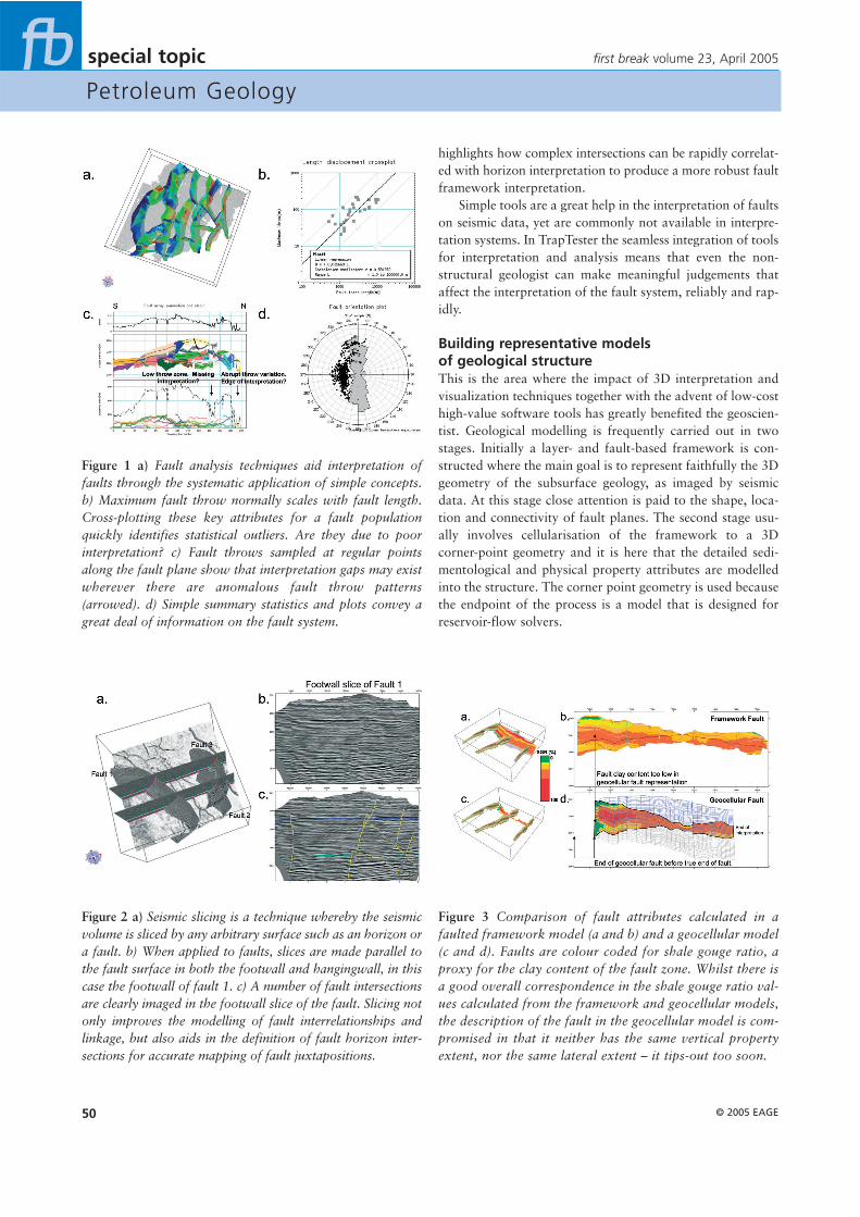
Seismic interpretation and QCFault correlation is an area where the structural toolkitsavailable provide immediate impact. For example, correla-tion of faults is greatly aided by understanding the distributionof displacement on their surfaces (Figure 1). By correlating thethrow pattern across a network of faults, it is possible to lookfor anomalies in the overall pattern that can correspond toareas of missing interpretation, or premature truncation of afault interpretation (Figure 1c).
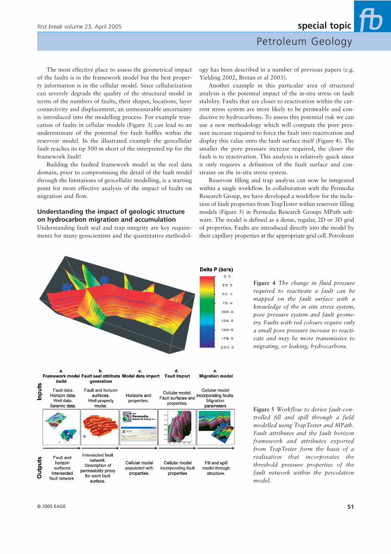
Defining fault intersections during interpretation can beproblematic. An established technique for analysing fault-fault intersections is to ‘slice’ the seismic volume parallel to afault surface, in both the hangingwall and footwall, andinterpret intersecting faults directly. An example in Figure 2
first break volume 23, April 2005
*E-mail: [email protected], Tel: +44(0)1790 753 472, Web: www.badleys.co.uk.
Best practice in structural geological analysis
Structural geology is seen too often as the domain of the specialist. Steve Dee,* Brett Freeman,Graham Yielding, Alan Roberts, and Peter Bretan of Badley Geoscience, document the casefor routine inclusion of structural geological analysis within company workflows.
S
Petroleum Geology
© 2005 EAGE50
special topic
highlights how complex intersections can be rapidly correlat-ed with horizon interpretation to produce a more robust faultframework interpretation.
Simple tools are a great help in the interpretation of faultson seismic data, yet are commonly not available in interpre-tation systems. In TrapTester the seamless integration of toolsfor interpretation and analysis means that even the non-structural geologist can make meaningful judgements thataffect the interpretation of the fault system, reliably and rap-idly.
Building representative models of geological structureThis is the area where the impact of 3D interpretation andvisualization techniques together with the advent of low-costhigh-value software tools has greatly benefited the geoscien-tist. Geological modelling is frequently carried out in twostages. Initially a layer- and fault-based framework is con-structed where the main goal is to represent faithfully the 3Dgeometry of the subsurface geology, as imaged by seismicdata. At this stage close attention is paid to the shape, loca-tion and connectivity of fault planes. The second stage usu-ally involves cellularisation of the framework to a 3Dcorner-point geometry and it is here that the detailed sedi-mentological and physical property attributes are modelledinto the structure. The corner point geometry is used becausethe endpoint of the process is a model that is designed forreservoir-flow solvers.
first break volume 23, April 2005
Figure 1 a) Fault analysis techniques aid interpretation offaults through the systematic application of simple concepts.b) Maximum fault throw normally scales with fault length.Cross-plotting these key attributes for a fault populationquickly identifies statistical outliers. Are they due to poorinterpretation? c) Fault throws sampled at regular pointsalong the fault plane show that interpretation gaps may existwherever there are anomalous fault throw patterns(arrowed). d) Simple summary statistics and plots convey agreat deal of information on the fault system.
Figure 3 Comparison of fault attributes calculated in afaulted framework model (a and b) and a geocellular model(c and d). Faults are colour coded for shale gouge ratio, aproxy for the clay content of the fault zone. Whilst there isa good overall correspondence in the shale gouge ratio val-ues calculated from the framework and geocellular models,the description of the fault in the geocellular model is com-promised in that it neither has the same vertical propertyextent, nor the same lateral extent – it tips-out too soon.
Figure 2 a) Seismic slicing is a technique whereby the seismicvolume is sliced by any arbitrary surface such as an horizon ora fault. b) When applied to faults, slices are made parallel tothe fault surface in both the footwall and hangingwall, in thiscase the footwall of fault 1. c) A number of fault intersectionsare clearly imaged in the footwall slice of the fault. Slicing notonly improves the modelling of fault interrelationships andlinkage, but also aids in the definition of fault horizon inter-sections for accurate mapping of fault juxtapositions.
Petroleum Geology
© 2005 EAGE 51
special topic
The most effective place to assess the geometrical impactof the faults is in the framework model but the best proper-ty information is in the cellular model. Since cellularizationcan severely degrade the quality of the structural model interms of the numbers of faults, their shapes, locations, layerconnectivity and displacement, an unmeasurable uncertaintyis introduced into the modelling process. For example trun-cation of faults in cellular models (Figure 3) can lead to anunderestimate of the potential for fault baffles within thereservoir model. In the illustrated example the geocellularfault reaches its tip 500 m short of the interpreted tip for theframework fault!
Building the faulted framework model in the real datadomain, prior to compromising the detail of the fault modelthrough the limitations of geocellular modelling, is a startingpoint for more effective analysis of the impact of faults onmigration and flow.
Understanding the impact of geologic structureon hydrocarbon migration and accumulationUnderstanding fault seal and trap integrity are key require-ments for many geoscientists and the quantitative methodol-
first break volume 23, April 2005
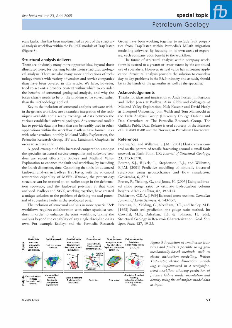
Figure 5 Workflow to derive fault-con-trolled fill and spill through a fieldmodelled using TrapTester and MPath.Fault attributes and the fault horizonframework and attributes exportedfrom TrapTester form the basis of arealisation that incorporates thethreshold pressure properties of thefault network within the percolationmodel.
ogy has been described in a number of previous papers (e.g.Yielding 2002, Bretan et al 2003).
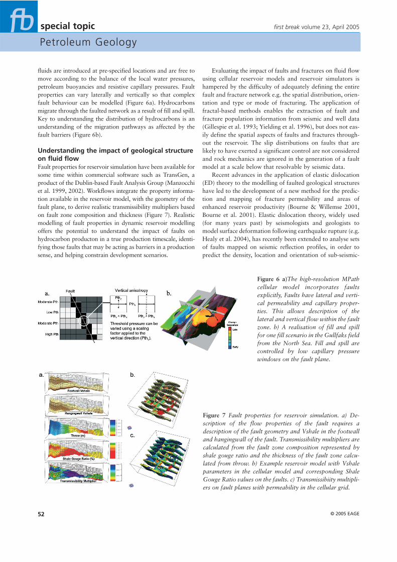
Another example in this particular area of structuralanalysis is the potential impact of the in-situ stress on faultstability. Faults that are closer to reactivation within the cur-rent stress system are more likely to be permeable and con-ductive to hydrocarbons. To assess this potential risk we canuse a new methodology which will compute the pore pres-sure increase required to force the fault into reactivation anddisplay this value onto the fault surface itself (Figure 4). Thesmaller the pore pressure increase required, the closer thefault is to reactivation. This analysis is relatively quick sinceit only requires a definition of the fault surface and con-straint on the in-situ stress system.
Reservoir filling and trap analysis can now be integratedwithin a single workflow. In collaboration with the PermediaResearch Group, we have developed a workflow for the inclu-sion of fault properties from TrapTester within reservoir fillingmodels (Figure 5) in Permedia Research Groups MPath soft-ware. The model is defined as a dense, regular, 2D or 3D gridof properties. Faults are introduced directly into the model bytheir capillary properties at the appropriate grid cell. Petroleum
Figure 4 The change in fluid pressurerequired to reactivate a fault can bemapped on the fault surface with aknowledge of the in situ stress system,pore pressure system and fault geome-try. Faults with red colours require onlya small pore pressure increase to reacti-vate and may be more transmissive tomigrating, or leaking, hydrocarbons.
Petroleum Geology
© 2005 EAGE52
special topic
fluids are introduced at pre-specified locations and are free tomove according to the balance of the local water pressures,petroleum buoyancies and resistive capillary pressures. Faultproperties can vary laterally and vertically so that complexfault behaviour can be modelled (Figure 6a). Hydrocarbonsmigrate through the faulted network as a result of fill and spill.Key to understanding the distribution of hydrocarbons is anunderstanding of the migration pathways as affected by thefault barriers (Figure 6b).
Understanding the impact of geological structureon fluid flowFault properties for reservoir simulation have been available forsome time within commercial software such as TransGen, aproduct of the Dublin-based Fault Analysis Group (Manzocchiet al. 1999, 2002). Workflows integrate the property informa-tion available in the reservoir model, with the geometry of thefault plane, to derive realistic transmissibility multipliers basedon fault zone composition and thickness (Figure 7). Realisticmodelling of fault properties in dynamic reservoir modellingoffers the potential to understand the impact of faults onhydrocarbon producton in a true production timescale, identi-fying those faults that may be acting as barriers in a productionsense, and helping constrain development scenarios.
Evaluating the impact of faults and fractures on fluid flowusing cellular reservoir models and reservoir simulators ishampered by the difficulty of adequately defining the entirefault and fracture network e.g. the spatial distribution, orien-tation and type or mode of fracturing. The application offractal-based methods enables the extraction of fault andfracture population information from seismic and well data(Gillespie et al. 1993; Yielding et al. 1996), but does not eas-ily define the spatial aspects of faults and fractures through-out the reservoir. The slip distributions on faults that arelikely to have exerted a significant control are not consideredand rock mechanics are ignored in the generation of a faultmodel at a scale below that resolvable by seismic data.
Recent advances in the application of elastic dislocation(ED) theory to the modelling of faulted geological structureshave led to the development of a new method for the predic-tion and mapping of fracture permeability and areas ofenhanced reservoir productivity (Bourne & Willemse 2001,Bourne et al. 2001). Elastic dislocation theory, widely used(for many years past) by seismologists and geologists tomodel surface deformation following earthquake rupture (e.g.Healy et al. 2004), has recently been extended to analyse setsof faults mapped on seismic reflection profiles, in order topredict the density, location and orientation of sub-seismic-
first break volume 23, April 2005
Figure 6 a)The high-resolution MPathcellular model incorporates faultsexplicitly, Faults have lateral and verti-cal permeability and capillary proper-ties. This allows description of thelateral and vertical flow within the faultzone. b) A realisation of fill and spillfor one fill scenario in the Gullfaks fieldfrom the North Sea. Fill and spill arecontrolled by low capillary pressurewindows on the fault plane.
Figure 7 Fault properties for reservoir simulation. a) De-scription of the flow properties of the fault requires adescription of the fault geometry and Vshale in the footwalland hangingwall of the fault. Transmissibility multipliers arecalculated from the fault zone composition represented byshale gouge ratio and the thickness of the fault zone calcu-lated from throw. b) Example reservoir model with Vshaleparameters in the cellular model and corresponding ShaleGouge Ratio values on the faults. c) Transmissibiity multipli-ers on fault planes with permeability in the cellular grid.
Petroleum Geology
© 2005 EAGE 53
special topic
scale faults. This has been implemented as part of the structur-al analysis workflow within the FaultED module of TrapTester(Figure 8).
Structural analysis delivers There are obviously many more opportunities, beyond thoseillustrated here, for deriving benefit from structural geologi-cal analysis. There are also many more applications of tech-nology from a wide variety of vendors and service companiesthan have been covered in this article. We have, however,tried to set out a broader context within which to considerthe benefits of structural geological analysis, and why thefocus clearly needs to be on the problem to be solved ratherthan the methodology applied.
Key to the inclusion of structural analysis software with-in the generic workflow are a seamless integration of the tech-niques available and a ready exchange of data between thevarious established software packages. Any structural toolkithas to provide data in a form that can be readily used in otherapplications within the workflow. Badleys have formed linkswith other vendors, notably Midland Valley Exploration, thePermedia Research Group, IFP and Landmark Graphics, inorder to achieve this.
A good example of this increased cooperation amongstthe specialist structural service companies and software ven-dors are recent efforts by Badleys and Midland ValleyExploration to enhance the fault-seal workflow, by includingthe fourth dimension, time. Combining the tools for advancedfault-seal analysis in Badleys TrapTester, with the advancedrestoration capability of MVE’s 3Dmove, the present-daystructure can be restored to an earlier stage in the deforma-tion sequence, and the fault-seal potential at that timeanalysed. Badleys and MVE, working together, have createda unique solution to the problem of defining the seal poten-tial of subsurface faults in the geological past.
The inclusion of structural analysis in more generic E&Pworkflows requires collaboration with other specialist ven-dors in order to enhance the joint workflow, taking theanalysis beyond the capability of any single discipline on itsown. For example Badleys and the Permedia Research
Group have been working together to include fault proper-ties from TrapTester within Permedia’s MPath migrationmodelling software. By focusing on its own areas of expert-ise, each company adds benefit to the workflow.
The future of structural analysis within company work-flows is assured to a greater or lesser extent by the continueduse of specialists. However, its real value lies in routine appli-cation. Structural analysis provides the solution to countlessday to day problems in the E&P industry and as such, shouldbe in the hands of the generalist as well as the specialist.
AcknowledgementsThanks for ideas and inspiration to Andy Foster, Jim Parsonsand Helen Jones at Badleys, Alan Gibbs and colleagues atMidland Valley Exploration, Nick Kusznir and David Healyat Liverpool University, John Walsh and Tom Manzocchi atthe Fault Analysis Group (University College Dublin) andDan Carruthers at The Permedia Research Group. TheGullfaks Public Data Release is used courtesy of the licenseesof PL050/PL050B and the Norwegian Petroleum Directorate.
ReferencesBourne, S.J. and Willemse, E.J.M. [2001] Elastic stress con-trol on the pattern of tensile fracturing around a small faultnetwork at Nash Point, UK. Journal of Structural Geology,23, 1753-1770.Bourne, S.J., Rijkels, L., Stephenson, B.J., and Willemse,E.J.M. [2001] Predictive modelling of naturally fracturedreservoirs using geomechanics and flow simulation.GeoArabia, 6, 27-41.Bretan, P., Yielding, G., and Jones, H. [2003] Using calibrat-ed shale gouge ratio to estimate hydrocarbon columnheights. AAPG Bulletin, 87, 397-413.Dahlstrom, C.D.A. [1969] Balanced cross-sections. CanadianJournal of Earth Sciences, 6, 743-757.Freeman, B., Yielding, G., Needham, D.T., and Badley, M.E.[1998] Fault seal prediction: the gouge ratio method. In:Coward, M.P., Daltaban, T.S. & Johnson, H. (eds),Structural Geology in Reservoir Characterization. Geol. Soc.Spec. Publ. 127, 19-25.
first break volume 23, April 2005
Figure 8 Prediction of small-scale frac-tures and faults is possible using geo-mechanically-based methods such aselastic dislocation modelling. WithinTrapTester, elastic dislocation model-ling is implemented in a straightfor-ward workflow allowing prediction offracture failure mode, orientation anddensity using the subsurface model dataas input.
Petroleum Geology
© 2005 EAGE54
special topic
Gillespie, P.A., Howard, C. H., Walsh, J.J., and Watterson, J.[1993] Measurement and characterisation of spatial distribu-tions of fractures. Tectonophysics, 225, 113-141.Healy, D., Yielding, G., and Kusznir, N. [2004] Fracture pre-diction for the 1980 El Asnam Algeria earthquake via elasticdislocation modelling. Tectonics, 23, TC6005. doc:10.1029/2003TC001575.Kusznir, N.J., Hunsdale, R., Roberts, A.M., and iSIMM Team.[2005] Timing and Magnitude of Depth-dependentLithosphere Stretching on the S. Lofoten and N. VøringContinental Margins Offshore Mid-Norway: Implications forSubsidence and Hydrocarbon Maturation at Volcanic RiftedMargins. In: Proceedings of the 6th Conference on PetroleumGeology of NW Europe. The Geological Society, London.Kusznir, N.J., Roberts, A.M., and Morley, C.K. [1995]Forward and Reverse Modelling of Rift Basin Formation. In:Lambiase, J. (Ed). Hydrocarbon Habitat in Rift Basins. SpecialPublication, 80, 33-56. The Geological Society, LondonManzocchi, T., Walsh, J.J., Nell, P., and Yielding, G. [1999]Fault transmissibility multipliers for flow simulation models.Petroleum Geoscience, 5, 53-63.Manzocchi, T., Heath, A.E., Walsh, J.J., and Childs, C. [2002]The representation of two phase fault-rock properties in flowsimulation models. Petroleum Geoscience 8 , 119-132.
Roberts, A.M., Kusznir, N.J., Yielding, G., and Styles, P.[1998] 2D flexural backstripping of extensional basins; theneed for a sideways glance. Petroleum Geoscience, 4, 327-338.Yielding, G. [2002] Shale Gouge Ratio - Calibration by geo-history. In: Koestler, A.G. and Hunsdale, R. (eds)Hydrocarbon Seal Quantification, NPF Special Publication11, 2002, 1-15.Yielding, G., Freeman, B., and Needham, D.T. [1997]Quantitative Fault Seal Prediction. AAPG Bulletin, 81, 897-917Yielding, G., Needham, T., and Jones, H. [1996] Sampling offault populations using sub-surface data: a review. Journal ofStructural Geology, 18, 135-146Yielding, G., Øverland, J.A., and Byberg, G. 1999.Characterisation of fault zones for reservoir modelling: Anexample from the Gullfaks Field, Northern North Sea. AAPGBulletin, 83, 6, 925-951.Yielding, G. And Roberts, A.M. 1992. Footwall uplift duringnormal faulting - implications for structural geometries in theNorth Sea. In: Larsen, R.M., Brekke, H., Larsen, B.T. andTalleraas, E. (Eds). Structural and Tectonic Modelling and itsApplication to Petroleum Geology. NPF Special Publication,1, 289-304, Elsevier, Amsterdam.
first break volume 23, April 2005
VEBA OIL OPERATIONS, LIBYAGEOPHYSICAL STAFF
Veba Oil Operations, a major oil producer in the Libyan oilindustry, is seeking accomplished petroleum exploration
geophysicists to augment the operations of their ExplorationDepartment at their head offices in the Mediterranean City of Tripoli.
SENIOR STAFF GEOPHYSICIST[MIN 15 YEARS’ EXPERIENCE]
STAFF GEOPHYSICIST[MIN 10 YEARS’ EXPERIENCE]Evaluates and interprets geophysical/seismic data together withgeological evidence in order to generate wildcat drilling prospectsand also provides expertise in locating appraisal and developmentwells. A wide-ranging background in 2D-3D seismic interpretationand prospect generation is sought whilst knowledge of Charismaworkstations [“Geoquest”], CPS-3 mapping software and seismictrace inversion is essential.
These positions are based living and working in Tripoli. Veba Oiloffer long term, married status, staff contracts with: salaries paidnet of local taxes/free furnished accommodation/annual leaveentitlement with airfares provided to point of origin twice peryear/medical insurance.
Please apply with a full CV/resume to: Peter Nicholls,Recruitment Administrator, Jawaby Oil Service,
15-17 Lodge Road, St Johns Wood, London, NW8 7JA, UK. Fax: 020 7314 6136. Email: [email protected]
Reference must be quoted in the subject area of emailapplications. Reference: VB41e.
2005 SEG Development & ProductionForumAustin, Texas � 15-19 May, 2005
Attenuation: What’s to Gain from Seismic Loss
The 2005 Development and Production Forum will deal withintrinsic seismic absorption (Q) in reservoir rocks, and whatinformation useful to the reservoir engineer and the petro-physicist can be gleaned from this phenomenon.
Visit the D&P Forum website at http://seg.org/meetings/devprod2005/If you require further information, please contact:
SEG Organizing Chairmen:Roger M. Turpening , General Chairman
Phone: (906) 487-1784 • E-mail: [email protected]
Sven Treitel, Technical Program ChairmanPhone: (918) 592-3103 • E-mail: [email protected]
Dr. Jerry Harris, Stanford University, will deliver the KeynoteAddress during the Sunday Evening session. Dr. JP Blangy, BP, willsummarize the achievements of the Forum on the final day.