benefits of allothermal biomass gasification for co- · pdf filebenefits of allothermal...
TRANSCRIPT
Benefits of Allothermal Biomass Gasification for Co-Firing
C.M. van der Meijden
A. van der Drift
B.J. Vreugdenhil
Presented at the 2nd Workshop on Cofiring Biomass with Coal, 27-28 March 2012, Copenhagen, Denmark
ECN-M--12-008 April 2012

IEA Co-firing with coal workshop 2012
BENEFITS OF ALLOTHERMAL BIOMASS
GASIFICATION FOR CO-FIRING
Christiaan van der Meijden
Bram van der Drift
Berend Vreugdenhil
Energy research Centre of the Netherlands (ECN)
ABSTRACT
Many countries have set obligations to reduce the CO2 emissions from coal fired boilers. Co-firing of biomass in existing coal fired power plants is an attractive solution to reduce CO2 emissions. Co-firing can be done by direct mixing of biomass with coal (direct co-firing) or by converting the biomass into a gas or liquid which is fired in a separate burner (indirect co-firing). Direct co-firing is a rather simple solution, but requires a high quality and expensive biomass fuel (e.g. wood pellets). Indirect co-firing requires an additional installation that converts the solid biomass into a gas or liquid, but has the advantage that it can handle a wide range of cheap biomass fuels (e.g. demolition wood) and most of the biomass ash components are separated from the gas before it enters the boiler. Separation of biomass ash can prevent fouling issues in the boiler.
Indirect co-firing, using biomass gasification technology, is already common practice. In Geertruidenberg (the Netherlands) a 80 MWth Lurgi CFB gasifier produces gas from demolition wood which is co-fired in the Amer PC boiler. In Ruien (Belgium) a 50 MWth Foster Wheeler fluidized bed gasifier is in operation.
The Energy research Centre of the Netherlands (ECN) developed a “second generation” allothermal gasifier called the MILENA gasifier. This gasifier has some major advantages over conventional fluidized bed gasifiers. The heating value of the produced gas is approximately 2.5 times higher than of gas produced by conventional bubbling / circulating fluidized bed gasifiers. This results in smaller adaptations to the membrane wall of the boiler for the gas injection, thus lower costs. A major disadvantage of most fluidized bed gasifiers is the incomplete conversion of the fuel. Typical fuel conversions vary between 90 and 95%. The remaining combustible material, also containing most of the biomass ash components, is blown out of the gasifier and removed from the gas stream by a cyclone to prevent ash entering the boiler. The calorific value of this carbon containing ash is lost. In allothermal gasifiers all the carbon containing ashes are combusted in the combustion section of the gasifier and the produced heat is used for the gasification process.
The MILENA gasification technology is demonstrated at lab-scale (25 kWth) and pilot scale (800 kWth). A demonstration plant (11.6 MWth biomass input) will be constructed in Alkmaar (the Netherlands). Demolition wood will be used as fuel.
2
TABLE OF CONTENTS
INTRODUCTION ...................................................................................................................................................... 3
BIOMASS GASIFICATION ......................................................................................................................................... 3
Types of gasifiers ................................................................................................................................................ 3
INDIRECT CO-FIRING CONCEPT ............................................................................................................................... 3
MILENA GASIFICATION PROCESS ............................................................................................................................ 4
ALLOTHERMAL VERSUS DIRECT GASIFICATION ...................................................................................................... 5
EXPERIMENTAL RESULTS ........................................................................................................................................ 7
Waste wood ........................................................................................................................................................ 7
Straw ................................................................................................................................................................... 8
CONCLUSIONS ........................................................................................................................................................ 9
REFERENCES ............................................................................................................................................................ 9

3
INTRODUCTION Many countries have set obligations to reduce the CO2 emissions from coal fired boilers. Co-firing of biomass in existing coal fired power plants is an attractive solution to reduce CO2 emissions. Co-firing can be done by direct mixing of biomass with coal (direct co-firing) or by converting the biomass into a gas or liquid which is fired in a separate burner (indirect co-firing). Direct co-firing is a rather simple solution, but requires a high quality and thus expensive biomass fuel (e.g. wood pellets). Indirect co-firing requires an additional installation that converts the solid biomass into a gas or liquid, but has the advantage that it can handle a wide range of cheap biomass fuels (e.g. demolition wood) and most of the biomass ash components are separated from the gas before it enters the boiler. Separation of biomass ash can prevent fouling issues in the boiler. Evaporation of alkalis can be prevented by keeping the gasification temperature low (e.g. <750°C). This will minimize the alkali load of the boiler.
BIOMASS GASIFICATION The term gasification is applied to processes which convert solid or liquid fuels into a combustible gas at high temperature. The heat required for the heating of the fuel and for the endothermic gasification reactions is supplied by the combustion of part of the fuel (direct gasification) or is supplied from an external source (indirect or allothermal gasification). The fuels for this external heat source are normally the residues from the gasification process (char and tar).
TYPES OF GASIFIERS Gasifiers can be divided into high temperature gasifiers (typical 1300 – 1500°C) which produce a syngas and medium temperature gasifiers (typical 850°C) which produce a producer gas. Syngas contains almost no hydrocarbons like methane. Entrained flow gasifiers are the most common example of high temperature gasifiers. Entrained flow gasifiers are developed to produce syngas from coal and oil residues. Gas coming from medium temperature gasifiers contains on energy basis up to 50% of hydrocarbons (mainly CH4, C2H4 and C6H6). For co-firing the presence of hydrocarbons is an advantage, because the heating value of the gas is higher. Hence, medium temperature gasification is the more logical choice for co-firing. The producer gas from medium temperature gasifiers also contains some tars. Tars are heavy hydrocarbons, which can cause fouling problems when the gas is cooled. For co-firing applications gas cooling is normally limited, so tar condensation should not be a problem as long as the wall temperature of the cooler is kept at a sufficient high temperature (e.g. >400°C).
The medium temperature gasifiers can be divided in fixed bed downdraft gasifiers and fluidized bed gasifiers. Downdraft bed gasifiers are widely used to generate gas for gas engines. The advantage of this type of gasifier is its simplicity and low investment cost. Downdraft gasifiers require a well defined fuel to keep the bed of fuel particles flowing nicely downwards. Scale-up is limited to typically 1 MWth biomass input. The conversion of the fuel is limited. Because of the fuel limitations, scale limitations and low fuel conversion downdraft gasifiers are not a logical choice for co-firing applications.
Fluidized bed gasifiers can handle a wide variety of fuels, with limited pretreatment. This technology is the more logical choice for large scale applications. Fluidized bed gasifiers can be divided into three main categories: Bubbling Fluidized Bed (BFB), Circulating Fluidized Bed (CFB) and indirect or allothermal twin bed concepts. All fluidized bed gasifiers use a bed material. That can be inert sand, the ash from the fuel or a
2
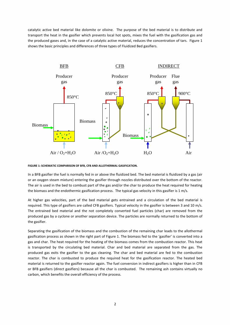
catalytic active bed material like dolomite or olivine. The purpose of the bed material is to distribute and transport the heat in the gasifier which prevents local hot spots, mixes the fuel with the gasification gas and the produced gases and, in the case of a catalytic active material, reduces the concentration of tars. Figure 1 shows the basic principles and differences of three types of Fluidized Bed gasifiers.
Air / O2+H2O
Biomass
Air /O2+H2O
Biomass
Biomass
Air H2O
Producer gas
Producer gas
Producer gas
Flue gas
BFB CFB INDIRECT
850°C 850°C 850°C 900°C
FIGURE 1: SCHEMATIC COMPARISON OF BFB, CFB AND ALLOTHERMAL GASIFICATION.
In a BFB gasifier the fuel is normally fed in or above the fluidized bed. The bed material is fluidized by a gas (air or an oxygen steam mixture) entering the gasifier through nozzles distributed over the bottom of the reactor. The air is used in the bed to combust part of the gas and/or the char to produce the heat required for heating the biomass and the endothermic gasification process. The typical gas velocity in this gasifier is 1 m/s.
At higher gas velocities, part of the bed material gets entrained and a circulation of the bed material is required. This type of gasifiers are called CFB gasifiers. Typical velocity in the gasifier is between 3 and 10 m/s. The entrained bed material and the not completely converted fuel particles (char) are removed from the produced gas by a cyclone or another separation device. The particles are normally returned to the bottom of the gasifier.
Separating the gasification of the biomass and the combustion of the remaining char leads to the allothermal gasification process as shown in the right part of Figure 1. The biomass fed to the ‘gasifier’ is converted into a gas and char. The heat required for the heating of the biomass comes from the combustion reactor. This heat is transported by the circulating bed material. Char and bed material are separated from the gas. The produced gas exits the gasifier to the gas cleaning. The char and bed material are fed to the combustion reactor. The char is combusted to produce the required heat for the gasification reactor. The heated bed material is returned to the gasifier reactor again. The fuel conversion in indirect gasifiers is higher than in CFB or BFB gasifiers (direct gasifiers) because all the char is combusted. The remaining ash contains virtually no carbon, which benefits the overall efficiency of the process.
3
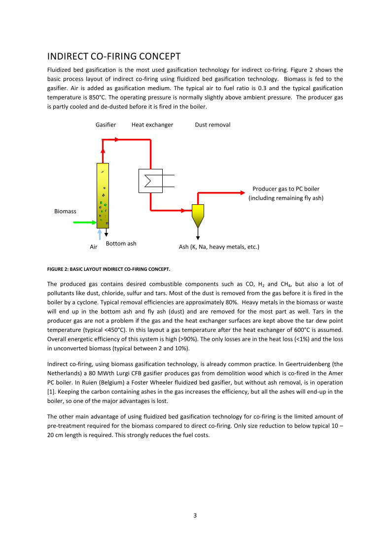
INDIRECT CO-FIRING CONCEPT Fluidized bed gasification is the most used gasification technology for indirect co-firing. Figure 2 shows the basic process layout of indirect co-firing using fluidized bed gasification technology. Biomass is fed to the gasifier. Air is added as gasification medium. The typical air to fuel ratio is 0.3 and the typical gasification temperature is 850°C. The operating pressure is normally slightly above ambient pressure. The producer gas is partly cooled and de-dusted before it is fired in the boiler.
FIGURE 2: BASIC LAYOUT INDIRECT CO-FIRING CONCEPT.
The produced gas contains desired combustible components such as CO, H2 and CH4, but also a lot of pollutants like dust, chloride, sulfur and tars. Most of the dust is removed from the gas before it is fired in the boiler by a cyclone. Typical removal efficiencies are approximately 80%. Heavy metals in the biomass or waste will end up in the bottom ash and fly ash (dust) and are removed for the most part as well. Tars in the producer gas are not a problem if the gas and the heat exchanger surfaces are kept above the tar dew point temperature (typical <450°C). In this layout a gas temperature after the heat exchanger of 600°C is assumed. Overall energetic efficiency of this system is high (>90%). The only losses are in the heat loss (<1%) and the loss in unconverted biomass (typical between 2 and 10%).
Indirect co-firing, using biomass gasification technology, is already common practice. In Geertruidenberg (the Netherlands) a 80 MWth Lurgi CFB gasifier produces gas from demolition wood which is co-fired in the Amer PC boiler. In Ruien (Belgium) a Foster Wheeler fluidized bed gasifier, but without ash removal, is in operation [1]. Keeping the carbon containing ashes in the gas increases the efficiency, but all the ashes will end-up in the boiler, so one of the major advantages is lost.
The other main advantage of using fluidized bed gasification technology for co-firing is the limited amount of pre-treatment required for the biomass compared to direct co-firing. Only size reduction to below typical 10 – 20 cm length is required. This strongly reduces the fuel costs.
Air
Biomass
Gasifier
Producer gas to PC boiler (including remaining fly ash)
Ash (K, Na, heavy metals, etc.)
Heat exchanger Dust removal
Bottom ash
4
MILENA GASIFICATION PROCESS The Energy research Centre of the Netherlands (ECN) has developed an allothermal biomass gasification technology, called the MILENA technology. The MILENA gasification technology has a high cold gas efficiency, produces a gas with a relatively high heating value and the fuel is completely converted into gas. The gasifier is fuel flexible. This makes the technology very suitable for co-firing applications.
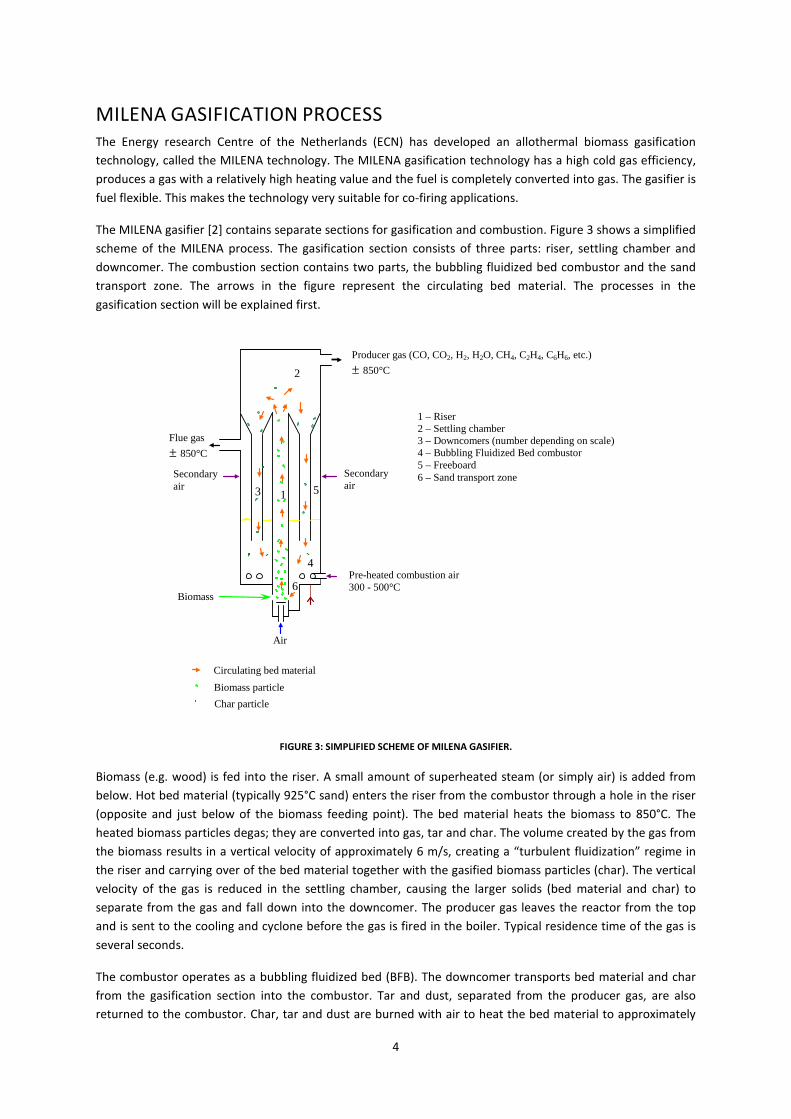
The MILENA gasifier [2] contains separate sections for gasification and combustion. Figure 3 shows a simplified scheme of the MILENA process. The gasification section consists of three parts: riser, settling chamber and downcomer. The combustion section contains two parts, the bubbling fluidized bed combustor and the sand transport zone. The arrows in the figure represent the circulating bed material. The processes in the gasification section will be explained first.
Air
Biomass
Circulating bed material Biomass particle Char particle
1
2
3
4
5
6
1 – Riser 2 – Settling chamber 3 – Downcomers (number depending on scale) 4 – Bubbling Fluidized Bed combustor 5 – Freeboard 6 – Sand transport zone
Producer gas (CO, CO2, H2, H2O, CH4, C2H4, C6H6, etc.) ± 850°C
Pre-heated combustion air 300 - 500°C
Flue gas ± 850°C
Secondary air
Secondary air
FIGURE 3: SIMPLIFIED SCHEME OF MILENA GASIFIER.
Biomass (e.g. wood) is fed into the riser. A small amount of superheated steam (or simply air) is added from below. Hot bed material (typically 925°C sand) enters the riser from the combustor through a hole in the riser (opposite and just below of the biomass feeding point). The bed material heats the biomass to 850°C. The heated biomass particles degas; they are converted into gas, tar and char. The volume created by the gas from the biomass results in a vertical velocity of approximately 6 m/s, creating a “turbulent fluidization” regime in the riser and carrying over of the bed material together with the gasified biomass particles (char). The vertical velocity of the gas is reduced in the settling chamber, causing the larger solids (bed material and char) to separate from the gas and fall down into the downcomer. The producer gas leaves the reactor from the top and is sent to the cooling and cyclone before the gas is fired in the boiler. Typical residence time of the gas is several seconds.
The combustor operates as a bubbling fluidized bed (BFB). The downcomer transports bed material and char from the gasification section into the combustor. Tar and dust, separated from the producer gas, are also returned to the combustor. Char, tar and dust are burned with air to heat the bed material to approximately
5
925°C. Flue gas leaves the reactor to be cooled, de-dusted and emitted. The heated bed material leaves the bottom of the combustor through a hole into the riser. No additional heat input is required; all heat required for the gasification process is produced by the combustion of the char, and dust in the combustor.
Accumulation of large ash particles in the bed, like stones, glass and nails, is prevented by removing bottom ash from the riser. The usable smaller bed particles are separated from the bottom ashes and recycled to the gasifier. The coarser particles are disposed.
The flue gas leaving the MILENA installation is cooled down to approximately 130°C and is cleaned in a bag house filter. If clean wood is used as a fuel no additional flue gas cleaning is required.
The hot producer gas from the gasifier contains several contaminants such as dust, tar, chloride and sulfur. Most of the carbon containing dust is removed from the producer gas by a cyclone and is returned to the combustion section of the MILENA. The tar in the gas is no problem as long as the gas is not cooled below the tar dew point (approx. 450°C).
ECN is still in discussion with several commercial partners for licensing the MILENA gasification technology. One of these potential partners is Dahlman (www.dahlman.nl), who is now offering commercial size Bio-CHP plants based on the MILENA gasification technology and OLGA gas cleaning technology. A 12 MW demonstration plant will be build in Alkmaar using demolition wood as fuel. The gas will be upgraded to natural gas quality.
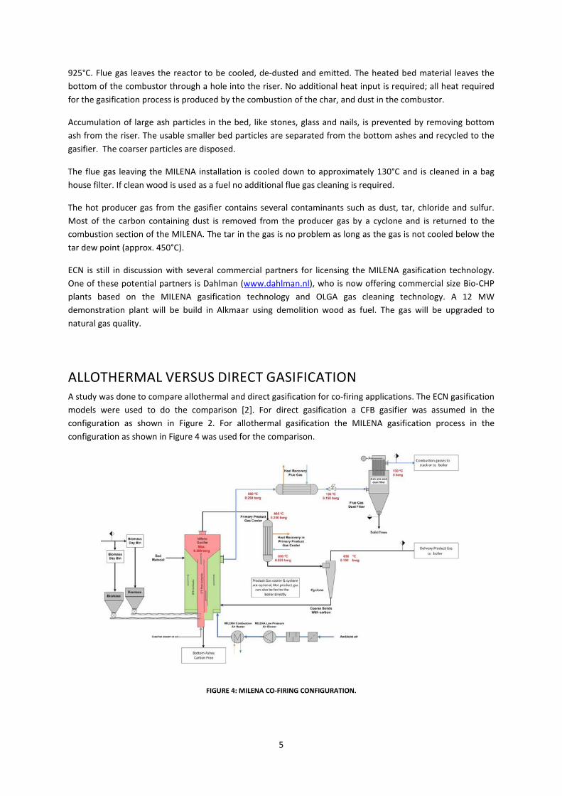
ALLOTHERMAL VERSUS DIRECT GASIFICATION A study was done to compare allothermal and direct gasification for co-firing applications. The ECN gasification models were used to do the comparison [2]. For direct gasification a CFB gasifier was assumed in the configuration as shown in Figure 2. For allothermal gasification the MILENA gasification process in the configuration as shown in Figure 4 was used for the comparison.
FIGURE 4: MILENA CO-FIRING CONFIGURATION.
6
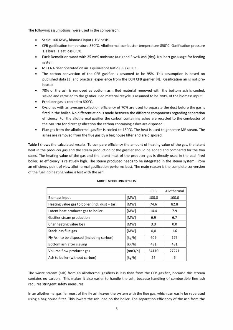
The following assumptions were used in the comparison:
• Scale: 100 MWth biomass input (LHV basis). • CFB gasification temperature 850°C. Allothermal combustor temperature 850°C. Gasification pressure
1.1 bara. Heat loss 0.5%. • Fuel: Demolition wood with 25 wt% moisture (a.r.) and 3 wt% ash (dry). No inert gas usage for feeding
system. • MILENA riser operated on air. Equivalence Ratio (ER) = 0.03. • The carbon conversion of the CFB gasifier is assumed to be 95%. This assumption is based on
published data [3] and practical experience from the ECN CFB gasifier [4]. Gasification air is not pre-heated.
• 70% of the ash is removed as bottom ash. Bed material removed with the bottom ash is cooled, sieved and recycled to the gasifier. Bed material recycle is assumed to be 7wt% of the biomass input.
• Producer gas is cooled to 600°C. • Cyclones with an average collection efficiency of 70% are used to separate the dust before the gas is
fired in the boiler. No differentiation is made between the different components regarding separation efficiency. For the allothermal gasifier the carbon containing ashes are recycled to the combustor of the MILENA for direct gasification the carbon containing ashes are disposed.
• Flue gas from the allothermal gasifier is cooled to 130°C. The heat is used to generate MP steam. The ashes are removed from the flue gas by a bag house filter and are disposed.
Table I shows the calculated results. To compare efficiency the amount of heating value of the gas, the latent heat in the producer gas and the steam production of the gasifier should be added and compared for the two cases. The heating value of the gas and the latent heat of the producer gas is directly used in the coal fired boiler, so efficiency is relatively high. The steam produced needs to be integrated in the steam system. From an efficiency point of view allothermal gasification performs best. The main reason is the complete conversion of the fuel, no heating value is lost with the ash.
TABLE I: MODELLING RESULTS.
CFB Allothermal
Biomass input [MW] 100,0 100,0
Heating value gas to boiler (incl. dust + tar) [MW] 74.6 82.8
Latent heat producer gas to boiler [MW] 14.4 7.9
Gasifier steam production [MW] 6.9 6.7
Char heating value loss [MW] 3.3 0.0
Stack loss flue gas [MW] 0,0 1.6
Fly Ash to be disposed (including carbon) [kg/h] 609 179
Bottom ash after sieving [kg/h] 431 431
Volume flow producer gas [nm3/h] 54110 27271
Ash to boiler (without carbon) [kg/h] 55 6
The waste stream (ash) from an allothermal gasifiers is less than from the CFB gasifier, because this stream contains no carbon. This makes it also easier to handle the ash, because handling of combustible fine ash requires stringent safety measures.
In an allothermal gasifier most of the fly ash leaves the system with the flue gas, which can easily be separated using a bag house filter. This lowers the ash load on the boiler. The separation efficiency of the ash from the
7
producer gas is low (70%), because a cyclone is used. Alternative solid separation devices like gas filters are not a realistic option, because the producer gas contains tars, which will clog the filters.
The results for the calculated amount of ash presented here must be seen as an indication, because in the used model all the ash components are treated the same, this is simplification. Further testing and improvement of the gasification model is required to make a more accurate prediction. The experimental results given in the next chapter show what fraction of the more relevant components will enter the boiler.
The volume of the gas that enters the boiler is significantly lower for allothermal gasification. The lower volume flow of producer gas will result in lower costs for boiler modifications and high temperature piping.
EXPERIMENTAL RESULTS Several tests were done in the lab-scale and pilot scale MILENA installations at ECN. Results for two of the most relevant fuels for indirect co-firing are given here.
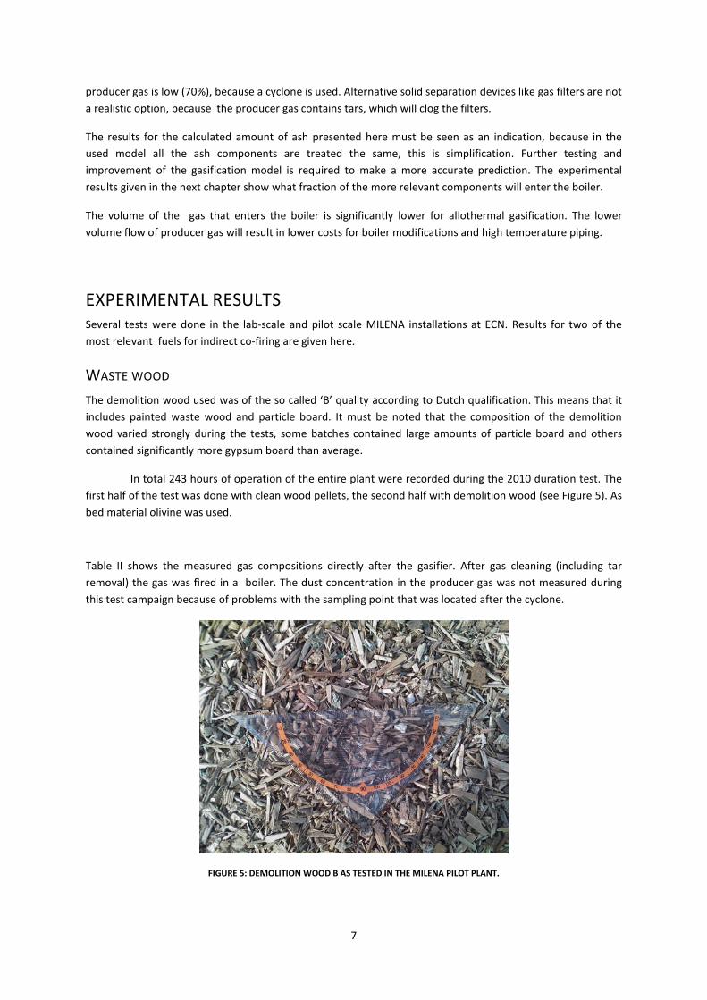
WASTE WOOD The demolition wood used was of the so called ‘B’ quality according to Dutch qualification. This means that it includes painted waste wood and particle board. It must be noted that the composition of the demolition wood varied strongly during the tests, some batches contained large amounts of particle board and others contained significantly more gypsum board than average.
In total 243 hours of operation of the entire plant were recorded during the 2010 duration test. The first half of the test was done with clean wood pellets, the second half with demolition wood (see Figure 5). As bed material olivine was used.
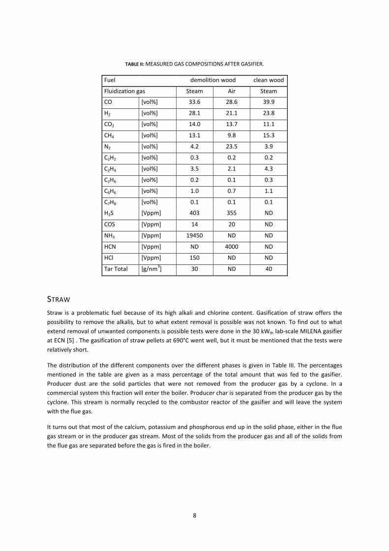
Table II shows the measured gas compositions directly after the gasifier. After gas cleaning (including tar removal) the gas was fired in a boiler. The dust concentration in the producer gas was not measured during this test campaign because of problems with the sampling point that was located after the cyclone.
FIGURE 5: DEMOLITION WOOD B AS TESTED IN THE MILENA PILOT PLANT.
8
TABLE II: MEASURED GAS COMPOSITIONS AFTER GASIFIER.
Fuel
demolition wood clean wood
Fluidization gas Steam Air Steam
CO [vol%] 33.6 28.6 39.9
H2 [vol%] 28.1 21.1 23.8
CO2 [vol%] 14.0 13.7 11.1
CH4 [vol%] 13.1 9.8 15.3
N2 [vol%] 4.2 23.5 3.9
C2H2 [vol%] 0.3 0.2 0.2
C2H4 [vol%] 3.5 2.1 4.3
C2H6 [vol%] 0.2 0.1 0.3
C6H6 [vol%] 1.0 0.7 1.1
C7H8 [vol%] 0.1 0.1 0.1
H2S [Vppm] 403 355 ND
COS [Vppm] 14 20 ND
NH3 [Vppm] 19450 ND ND
HCN [Vppm] ND 4000 ND
HCl [Vppm] 150 ND ND
Tar Total [g/nm3] 30 ND 40
STRAW Straw is a problematic fuel because of its high alkali and chlorine content. Gasification of straw offers the possibility to remove the alkalis, but to what extent removal is possible was not known. To find out to what extend removal of unwanted components is possible tests were done in the 30 kWth lab-scale MILENA gasifier at ECN [5] . The gasification of straw pellets at 690°C went well, but it must be mentioned that the tests were relatively short.
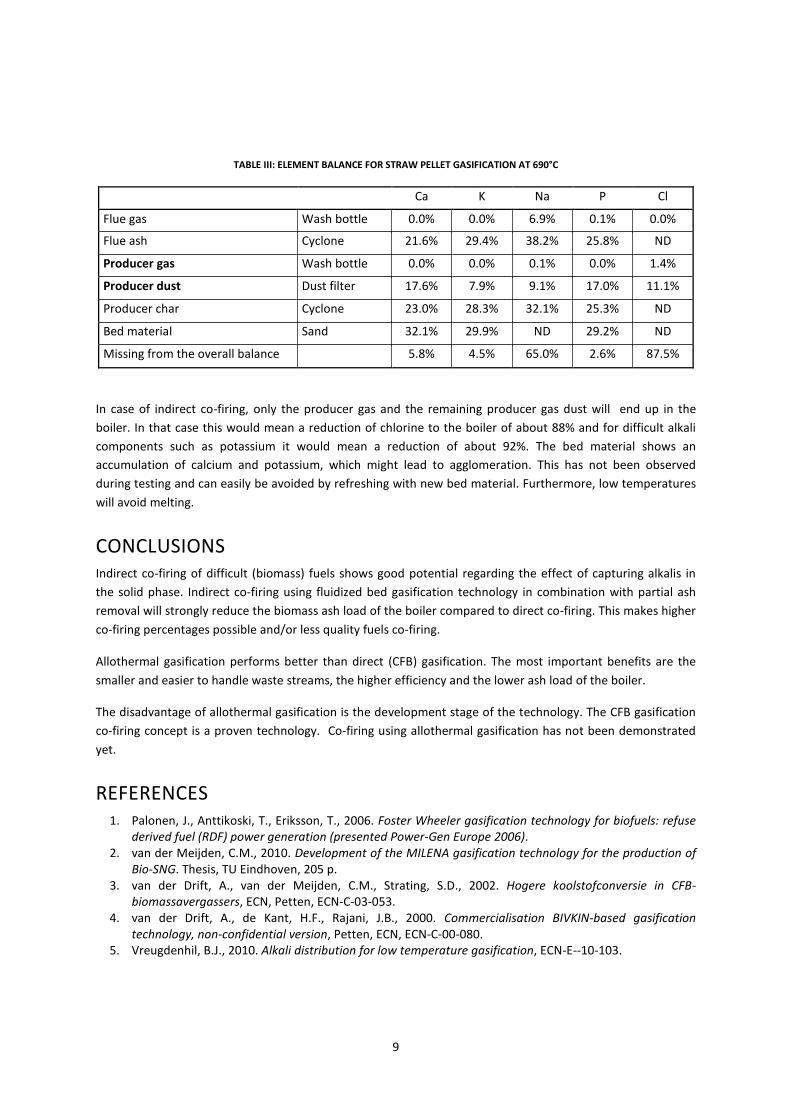
The distribution of the different components over the different phases is given in Table III. The percentages mentioned in the table are given as a mass percentage of the total amount that was fed to the gasifier. Producer dust are the solid particles that were not removed from the producer gas by a cyclone. In a commercial system this fraction will enter the boiler. Producer char is separated from the producer gas by the cyclone. This stream is normally recycled to the combustor reactor of the gasifier and will leave the system with the flue gas.
It turns out that most of the calcium, potassium and phosphorous end up in the solid phase, either in the flue gas stream or in the producer gas stream. Most of the solids from the producer gas and all of the solids from the flue gas are separated before the gas is fired in the boiler.
9
TABLE III: ELEMENT BALANCE FOR STRAW PELLET GASIFICATION AT 690°C
Ca K Na P Cl
Flue gas Wash bottle 0.0% 0.0% 6.9% 0.1% 0.0%
Flue ash Cyclone 21.6% 29.4% 38.2% 25.8% ND
Producer gas Wash bottle 0.0% 0.0% 0.1% 0.0% 1.4%
Producer dust Dust filter 17.6% 7.9% 9.1% 17.0% 11.1%
Producer char Cyclone 23.0% 28.3% 32.1% 25.3% ND
Bed material Sand 32.1% 29.9% ND 29.2% ND
Missing from the overall balance 5.8% 4.5% 65.0% 2.6% 87.5%
In case of indirect co-firing, only the producer gas and the remaining producer gas dust will end up in the boiler. In that case this would mean a reduction of chlorine to the boiler of about 88% and for difficult alkali components such as potassium it would mean a reduction of about 92%. The bed material shows an accumulation of calcium and potassium, which might lead to agglomeration. This has not been observed during testing and can easily be avoided by refreshing with new bed material. Furthermore, low temperatures will avoid melting.
CONCLUSIONS Indirect co-firing of difficult (biomass) fuels shows good potential regarding the effect of capturing alkalis in the solid phase. Indirect co-firing using fluidized bed gasification technology in combination with partial ash removal will strongly reduce the biomass ash load of the boiler compared to direct co-firing. This makes higher co-firing percentages possible and/or less quality fuels co-firing.
Allothermal gasification performs better than direct (CFB) gasification. The most important benefits are the smaller and easier to handle waste streams, the higher efficiency and the lower ash load of the boiler.
The disadvantage of allothermal gasification is the development stage of the technology. The CFB gasification co-firing concept is a proven technology. Co-firing using allothermal gasification has not been demonstrated yet.
REFERENCES 1. Palonen, J., Anttikoski, T., Eriksson, T., 2006. Foster Wheeler gasification technology for biofuels: refuse
derived fuel (RDF) power generation (presented Power-Gen Europe 2006). 2. van der Meijden, C.M., 2010. Development of the MILENA gasification technology for the production of
Bio-SNG. Thesis, TU Eindhoven, 205 p. 3. van der Drift, A., van der Meijden, C.M., Strating, S.D., 2002. Hogere koolstofconversie in CFB-
biomassavergassers, ECN, Petten, ECN-C-03-053. 4. van der Drift, A., de Kant, H.F., Rajani, J.B., 2000. Commercialisation BIVKIN-based gasification
technology, non-confidential version, Petten, ECN, ECN-C-00-080. 5. Vreugdenhil, B.J., 2010. Alkali distribution for low temperature gasification, ECN-E--10-103.