basis for ngnp reactor design down-selection 2010/03b - basis for ngnp reactor...inl/ext-10-19565....
TRANSCRIPT

INL/EXT-10-19565
Basis for NGNP Reactor Design Down-Selection
August 2010

DISCLAIMER
This information was prepared as an account of work sponsored by an agency of the U.S. Government. Neither the U.S. Government nor any agency thereof, nor any of their employees, makes any warranty, expressed or implied, or assumes any legal liability or responsibility for the accuracy, completeness, or usefulness, of any information, apparatus, product, or process disclosed, or represents that its use would not infringe privately owned rights. References herein to any specific commercial product, process, or service by trade name, trade mark, manufacturer, or otherwise, does not necessarily constitute or imply its endorsement, recommendation, or favoring by the U.S. Government or any agency thereof. The views and opinions of authors expressed herein do not necessarily state or reflect those of the U.S. Government or any agency thereof.

INL/EXT-10-19565
Basis for NGNP Reactor Design Down-Selection
August 2010
Idaho National Laboratory Next Generation Nuclear Plant Project
Idaho Falls, Idaho 83415
Prepared for the U.S. Department of Energy Office of Nuclear Energy
Under DOE Idaho Operations Office Contract DE-AC07-05ID14517


v
EXECUTIVE SUMMARY
This paper evaluates the extent of technology development, design, and licensing maturity anticipated to be required for both pebble bed and prismatic reactor design to determine if there are credible differentiators that would form the basis for design selection for NGNP. It does not develop a business decision based on the economics, business model, and resulting business case because these will vary based on the reactor application. The selection of the reactor type, module ratings, number of modules, configuration of the balance of plant, and other design options will be made on the basis of optimizing the business case for the application. These are not decisions that can be made on a generic basis.
Conclusions:
Based on the comparison described below, the following conclusions are reached:
There currently is no substantive technical differentiation that could provide the basis for choosing a reactor design—whether pebble bed or prismatic. The conceptual-level design currently ongoing is not expected to change this conclusion.
There currently is not sufficient confidence in the costs and plant economic evaluations performed to date to use these as differentiating factors, even if the business model were known.
It is expected that the designs will need to be matured well into the preliminary design phase and the licensing basis matured to support impending submittal of a combined construction and operating licensing application before possible differentiating features will be identified. More specifically:
- The design of the systems and equipment will need to be sufficiently detailed to permit equipment sizing and layout and transient analyses to be completed
- The design of safety related systems and equipment will need to be sufficiently detailed to permit safety analyses, including accident frequencies and consequences to be determined
- The fundamental licensing requirements will need to be defined through the preapplication process
- The industrial application to which the FOAK NGNP plant will be applied needs to be identified and the business case for this application needs to be developed.
It is judged that sufficient technical differences will not be identified between the pebble bed and prismatic reactor concepts to make a selection for further development on a generic basis. In commercial application, the selection of which reactor design to apply is expected to be a function of the specific application, the licensing basis and the business case economics than the technical differences. These differentiators will require design maturation well into preliminary design to provide adequate confidence.
Basis for Conclusions
The above conclusions are based on detailed comparison of these reactor designs in the following areas:
Configuration, thermal rating, and operating conditions, including comparison of over 30 specific design characteristics of two pebble bed reactor configurations and four prismatic reactor configurations that have been conceptualized as part of work completed to-date in the NGNP Project. This review included evaluation and assessment of advantages of one design over the other for both pebble bed and prismatic reactor technologies in the following areas:
- Fuel composition, packing fraction, enrichment, and burnup

vi
- Core thermal fluid transport, including pressure drop, coolant flow, convective heat transfer, non-convective heat transfer
- Core neutronics and fuel management, including refueling, excess reactivity, power peaking, analysis
- Graphite
- Instrumentation and control
- Source term
- Accident sequence
- Power output
- Proliferation.
Technical viability to supply the variety of energy forms at the required conditions (e.g., thermal rating, temperature, pressure) for the wide range of industrial processes identified to-date by the NGNP Project as candidates for application of the high temperature gas-cooled reactor (HTGR) technology.
Research and development (R&D) required to support design and licensing activities, including review of the objectives and coverage of the R&D requirements of both reactor designs, including the Fuel Development and Qualification Program, Graphite Development and Qualification Program, High Temperature Materials Qualification Program, and the Methods Validation Program.
Technology development required to complete the design effort and support licensing of the reactor concept by the U.S. Nuclear Regulatory Commission. This comparison examined the summary of the design development needs identified in the NGNP Project for each reactor design in the Technology Development Roadmaps prepared as part of the NGNP Project Risk Management Plan.
Advancement of the designs for both the pebble bed and prismatic reactor based plants through preliminary design is necessary to establish if there is a technical basis to select one design over the other for further development. Of highest priority are the identification and completion of the design of safety related structures, systems, and components to support development of the Combined License Application (COLA) in 2014. To meet the scheduled provisions of the Energy Policy Act of 2005 (EPAct), this work needs to be completed in the 2013 time frame for submittal of the COLA in 2014. To achieve this level of design development in this time frame, DOE needs to engage now with industry and expedite the formation of the public-private partnership, including development of the necessary strategy, schedule, and cost sharing provisions. The work completed by the NGNP Project is sufficient to inform this development.
It is the judgment of the NGNP Project that throughout the design and licensing process no differentiating technical factors will be identified that justify selection of one reactor design (i.e., pebble bed or prismatic) over the other. It is anticipated that the selection of reactor design will be made by the future owner of the plant based on specific licensing basis requirements and the business case. Potential end users and owners with whom the NGNP Project has discussed the application of this technology support developing two reactor plant designs (based on pebble bed and prismatic reactors) so they have a choice to better manage development risk, to promote competition and to provide flexibility in selecting the best alternative for the application and the business case. The implementation of parallel development paths has benefit to the NGNP Project by providing an alternative in the event major problems are encountered in one of the paths.
The NGNP Industry Alliance has proposed a NGNP Project Implementation Strategy1 that promotes development of a public-private partnership and proposes processes to ensure that both the government and the private sector perspectives are included in making major decisions on the paths forward for the NGNP Project. This strategy has an option to carry two plant designs to the point where a decision is to

vii
be made on building one or both plants. Under this option, this decision would be made by the private sector, which would then bear 100% of the costs for the final design, construction and operation of the plant(s). This appropriately places the responsibility for this decision and the costs for the plant on the owner(s).
viii
CONTENTS
EXECUTIVE SUMMARY .......................................................................................................................... v
ACRONYMS ................................................................................................................................................ x
1. INTRODUCTION .............................................................................................................................. 1
1.1 Purpose ..................................................................................................................................... 1
1.2 Background .............................................................................................................................. 1
1.3 Approach .................................................................................................................................. 2
2. REACTOR PLANT CONFIGURATIONS, THERMAL RATINGS, AND OPERATING CONDITIONS .................................................................................................................................... 3
2.1 Reactor Designs ....................................................................................................................... 3
2.2 Pebble Bed and Prismatic Reactor Fuel Designs ..................................................................... 8 2.2.1 Pebble Bed Fuel Elements .......................................................................................... 8 2.2.2 Prismatic Fuel Elements .............................................................................................. 9
2.3 Reactor Plant Characteristics ................................................................................................. 10
3. COMPARISON OF REACTOR CONCEPTS ................................................................................. 14
3.1 Comparing Configuration, Thermal Rating and Operating Conditions ................................. 14
3.2 Comparing Core Designs ....................................................................................................... 14
4. R&D REQUIRED TO SUPPORT DESIGN AND LICENSING ACTIVITIES ............................. 19
4.1 Fuel Development and Qualification ..................................................................................... 19
4.2 Graphite Development and Qualification .............................................................................. 19
4.3 High Temperature Materials .................................................................................................. 20
4.4 Design and Safety Methods Validation .................................................................................. 20
5. TECHNOLOGY DEVELOPMENT REQUIRED TO COMPLETE DESIGN EFFORT AND TO SUPPORT LICENSING OF THE REACTOR CONCEPT BY THE NRC .................... 22
6. CONCLUSION ................................................................................................................................ 24
6.1 General ................................................................................................................................... 24
7. REFERENCES ................................................................................................................................. 26
FIGURES Figure 1. History of HTGR plants. ............................................................................................................... 3
Figure 2. WEC/PBMR team pebble bed reactor FY 2007 NGNP preconceptual design. ............................ 4
Figure 3. AREVA team prismatic reactor FY 2907 NGNP preconceptual design. ...................................... 5
Figure 4. General Atomics team prismatic reactor FY 2007 NGNP preconceptual design. ......................... 5
Figure 5. WEC/PBMR team reduced reactor operating temperature configuration—steam and electricity only. ............................................................................................................................. 6

ix
Figure 6. AREVA/GA – Revised prismatic reactor based commercial steam and electricity supply plant. ............................................................................................................................................. 7
Figure 7. WEC/PBMR team commercial plant configuration. ..................................................................... 7
Figure 8. Pebble bed fuel element. ................................................................................................................ 8
Figure 9. TRISO fuel particle configuration and coating purposes. ............................................................. 9
Figure 10. Prismatic reactor fuel particles, compacts and assemblies. ....................................................... 10
TABLES Table 1. Summary of specific pebble bed and prismatic reactor design characteristics. ............................ 12
Table 2. Comparison of specific pebble bed and prismatic reactor design characteristics. ........................ 15
Table 3. Pebble bed reactor vs. prismatic-block reactor—a summary of differences. ................................ 17
Table 4. Summary of critical PASSCs ........................................................................................................ 23
x
ACRONYMS
AGR Advanced Gas Reactor
ASME American Society of Mechanical Engineers
ATR Advanced Test Reactor
COLA Combined License Application
DOE Department of Energy
DTF designed-to-fail
EPAct Energy Policy Act of 2005
FHS fuel handling system
FOA Financial Offer of Assistance Office
GA General Atomics
GT-MHR Gas Turbine-Modular Helium Reactor
HTGR high temperature gas-cooled reactor
HTR high temperature reactor
HTTR High Temperature Test Reactor
IHX intermediate heat exchanger
IPyC inner pyrocarbon
LEU low enriched uranium
LWR light water reactor
NGNP Next Generation Nuclear Plant
NRC Nuclear Regulatory Commission
OPyC outer pyrocarbon
PBMR Pebble-Bed Modular Reactor (Pty) ltd.
PBR pebble bed reactor
PCDR preliminary conceptual design report
PIE post-irradiation examination
PMR prismatic modular reactor
R&D research and development
RPV reactor pressure vessel
TDRM Technology Development Road Map
TRISO tri-isotropic
TRL technology readiness level

xi
VHTR very high temperature reactor
WEC Westinghouse Electric Company
1
Basis for NGNP Reactor Design Down-Selection
1. INTRODUCTION
1.1 Purpose
This paper evaluates the extent of technology development, design, and licensing maturity anticipated to be required for both pebble bed and prismatic reactor design to determine if there are credible differentiators that would form the basis for design selection for NGNP. It does not develop a business decision based on the economics, business model, and resulting business case because these will vary based on the reactor application. The selection of the reactor design, module ratings, number of modules, configuration of the balance of plant, and other design options will be made on the basis of optimizing the business case for the application. These are not decisions that can be made on a generic basis.
1.2 Background
In 2006, the NGNP Project was initiated at Idaho National Laboratory by the Department of Energy (DOE) as part of the Generation IV Nuclear Energy Systems technology roadmap and pursuant to the Energy Policy Act of 2005 (EPAct).2 The principal objective of the NGNP Project is to support commercialization of the high temperature gas-cooled reactor (HTGR) technology. Beginning in the latter part of 2006, the NGNP Project initiated tasks with three supplier teams led by Westinghouse Electric Company/Pebble-Bed Modular Reactor Ltd (pty) (WEC/PBMR), AREVA, and General Atomics (GA) with the objective of developing commercial reactor designs applying the pebble bed and prismatic block reactor concepts. These plants were designed to demonstrate the ability of the HTGR technology to produce electricity and hydrogen.
Subsequent to that work, discussions with potential end users of the HTGR technology determined that the end users are interested in the technology for a broader range of applications than just electricity and hydrogen production. Since the HTGR is helium-cooled and graphite-moderated, it can operate at reactor outlet temperatures much higher than conventional light water reactor (LWR) technology. Accordingly, it can be applied in many industrial applications as a substitute for burning of fossil fuels, such as natural gas, in addition to producing electricity—the principal application of current LWRs. At the time of this writing, several applications of the HTGR technology to industrial applications have been evaluated by the NGNP Project. These include supplying electricity, steam, and high-temperature gas to a wide range of industrial processes and producing hydrogen and oxygen for use in petrochemical, refining, chemical, and fertilizer plants. Plants using both the pebble bed and prismatic block reactor designs have been used in the evaluations of these applications.
In September 2009, DOE issued a Funding Opportunity Announcement (FOA) to perform conceptual-level design work for the NGNP first-of-a-kind plant.3 In November 2009, the suppliers submitted proposals in response to this FOA. This work is to be completed by the end of September 2010. It is judged that the limited scope of the conceptual-level design work to be completed via agreement derived from the FOA will not significantly progress the state of either the pebble bed or prismatic technology from their current states. This paper compares the two reactor design concepts on technical bases and establishes what information on the technical characteristics is necessary to make an informed decision on whether one design should be favored over the other in completing the NGNP Project.

2
1.3 Approach
The key features of pebble bed and prismatic block reactor designs are compared based on the following attributes:
Configuration, thermal rating, and operating conditions
Technical viability to supply the several energy forms at the required conditions (e.g., thermal rating, temperature, pressure) needed to supply the energy needs of the wide range of industrial processes evaluated to-date by the NGNP Project as candidates for application of the HTGR technology
Research and development (R&D) required to support design and licensing activities
Technology development required to complete design efforts and support licensing of the reactor concept by the U.S. Nuclear Regulatory Commission (NRC).
Other factors could be used to assess the advantages of one reactor design over the other, for example, the assessment could compare plant capital, operating costs, lifetime and other factors affecting the economic viability of the designs, but as stated in the purpose, this was not done for this comparison for the following reasons:
None of these factors are developed for either reactor design to the level of confidence required to make a viable assessment of one design versus the other. Completion of the full conceptual design effort is required of both designs to provide enough confidence in the estimate of capital and operating costs, plant lifetime, projected availability, and other factors that need to be considered in this assessment. The limited scope of the conceptual design work that will be completed under the provisions of the FOA will not be sufficient for this purpose.
These factors may not be significant in the selection of either the pebble bed or the prismatic reactor design for a specific application. The selection of the type of reactor, the module ratings, the number of modules, the configuration of the balance-of-plant and a myriad of other design selections will be made on the basis of optimizing the business case for the application. These are not decisions that can be made on a generic basis with any confidence within a project that has the objective of commercializing a technology rather than a specific design, particularly at an early stage.

3
2. REACTOR PLANT CONFIGURATIONS, THERMAL RATINGS, AND OPERATING CONDITIONS
2.1 Reactor Designs
HTGR technology is not a new technology. Beginning with the UK 20 MWth Dragon test plant in 1963, seven commercial scale and research HTGR plants have been built and operated worldwide. Figure 1 shows each of these plants, identifying the type of reactor design, rating of the plant, and years of operation. It also shows that there are two types of reactor designs: prismatic and pebble bed. The two plants still operating for research purposes are the prismatic High Temperature Engineering Test Reactor (HTTR) in Japan and the Pebble Bed High Temperature Reactor (HTR-10) in China. There are no HTGR plants in commercial operation at the time of this writing, but the Chinese have announced their intention to build one over the next several years, based on the pebble bed HTR design.
Figure 1. History of HTGR plants.
The HTTR and HTR-10 reactor designs are similar to those being pursued by the NGNP Project. They have safety characteristics stemming from material, nuclear, and thermal hydraulic characteristics that mitigate the severity of postulated licensing basis events (e.g., loss of coolant and reactivity transients) and reduce the release of the associated radiological source terms and calculated dose consequences.4,5 These characteristics and the higher operating temperatures of these reactors provide advantages in their co-location with industrial applications. These characteristics support the principal objective of the NGNP Project to commercialize this technology.

4
Since the initiation of the NGNP Project in 2006, several plant configurations and operating conditions have been conceptualized for application of the HTGR technology in industrial processes for both the pebble bed and prismatic block reactor concepts. The preconceptual design work in FY 2007 developed pebble bed and prismatic block reactor based plant designs for the production of electricity and hydrogen in accordance with the provisions of the EPAct.6 These plant concepts have reactor outlet temperatures in the range 900 to 950C and reactor module thermal power ratings of 500 to 600 MWth. These plant configurations included direct Brayton cycle gas turbines and gas-to-gas intermediate heat exchangers (IHXs) in the primary helium loop and steam generators in a secondary gas loop. Figures 2, 3, and 4 summarize the configurations developed in this work. Table 1 summarizes key parameters for these designs. Results of comparisons of the noncore design parameters are summarized in Table 2. Comparisons of the core parameters are summarized in Table 3.
Indirect configuration producing electricity and hydrogen Annular Pebble Bed Reactor
Figure 2. WEC/PBMR team pebble bed reactor FY 2007 NGNP preconceptual design.

5
Figure 3. AREVA team prismatic reactor FY 2907 NGNP preconceptual design.
Figure 4. General Atomics team prismatic reactor FY 2007 NGNP preconceptual design.

6
Subsequent to this work the HTGR suppliers recommended reducing the reactor outlet temperatures. The bases for these recommendations included:
Reductions in the technical risks associated with developing the high temperature materials and IHX designs necessary to implement the FY 2007 preconceptual designs within the schedule set for initial operation of the NGNP first-of-a-kind plant (2021). The WEC/PBMR team recommended retaining the IHX to reduce the water ingress risk associated with positioning the steam generator in the primary loop. The AREVA and GA teams concluded that the risk was not significant; this configuration had been used with success in prior deployment of gas reactors.
Increased margin in the qualification of reactor fuel, graphite, and high temperature metallic materials that would reduce licensing risk. The NGNP R&D Programs are designed to qualify these materials at conditions that encompass the higher operating temperatures, (e.g., 950°C reactor outlet temperature). Accordingly, operation at lower temperatures increases margin to the qualification temperatures.
Discussions of the energy needs with a broad range of potential end users of the technology that concluded many of these energy needs could be met with a lower temperature plant producing only steam and electricity, (e.g., co-generation applications wherein only steam and electricity are required, extraction of bitumen from oil sands)
As noted, the WEC/PBMR team retained the IHX in the primary loop, but the AREVA and GA teams also recommended eliminating it and moving the steam generator into the primary loop.7,8 In all cases, the plant would only supply steam and electricity rather than hydrogen. Figures 5 and 6 and Table 1 summarize the revised plant configurations and reactor characteristics proposed by the suppliers at that time.
In mid-2009, the WEC/PBMR team further revised the recommended pebble bed reactor design from an annular core to a cylindrical core with a reduction in the thermal rating of the reactor from 500 MWth to the range of 200 to 250 MWth.9 This team also concluded that it was acceptable to position the steam generator in the primary loop. The configuration of this plant design and reactor characteristics are shown in Figure 7 and Table 1.
Figure 5. WEC/PBMR team reduced reactor operating temperature configuration—steam and electricity only.
NHSS Island Process Area
PBMRSG
HPT IPT
SGSG
HPT IPT
PBMR IHX SG
HPT IPT
SGSG
HPT IPT ~
PCS
SHTS
PHTS
Steam to Process
PHTS SHTS

7
Figure 6. AREVA/GA – Revised prismatic reactor based commercial steam and electricity supply plant.
Figure 7. WEC/PBMR team commercial plant configuration.
He
Circulator
Generator
Water/steam
600 MWt Rx core
750°C
S.G.
Primary Loop Steam
turbine
Steam isolation valves
~550°C
Condenser
LPReboiler
HPReboiler
LP Process Steam
HP Process Steam
Process CondensateReturn
ProcessWater
CleanupProcess steam

8
2.2 Pebble Bed and Prismatic Reactor Fuel Designs
Referring to Figures 2 through 7 (above), the clearest distinction between the two reactor module concepts is the reactor core. The pebble bed core is made up of spherical fuel elements that are continuously flowing downward through either an annular or cylindrical volume made up of graphite reflector blocks. Once a spherical fuel element passes through the core it is collected, examined for physical damage and the level of burnup, and, if acceptable, returned to the top of the core for further operation. If it is damaged or has reached its burnup limit, it is removed from service and sent to used fuel storage. New fuel spheres are added as required to maintain the appropriate inventory in the core. In this manner, the pebble bed reactor is continuously refueled and needs to be shutdown only for maintenance, nominally every 5 to 6 years.
The prismatic core is made up of graphite blocks that contain embedded fuel compacts. The fuel blocks are arranged in an annular configuration made up of center and outer graphite reflector blocks. The core made up of these fuel blocks has a cycle lifetime of 18 to 24 months. The fuel blocks are shuffled and replaced on a batch basis using specialized fuel handling equipment. This equipment is designed to operate through special ports in the reactor vessel head so removal of the vessel head is not required for refueling. Refueling is projected to require ~21 days. Reflector blocks can also be replaced during refueling.
Both reactor concepts use the same fuel concepts but with the different fuel element configurations.
2.2.1 Pebble Bed Fuel Elements
Figure 8 shows the makeup of the pebble bed reactor spherical fuel elements. The fuel element consists of a matrix graphite body pressed into a spherical shape. A fuel sphere is divided into two regions. The inner spherical region is known as the fuel region, and the outer shell surrounding the fuel region is known as the fuel-free region. The fuel region of each fuel sphere contains a large number of evenly distributed TRISO-coated fuel particles; there are no particles in the fuel-free region. The design of the coated particles and fuel sphere, including their nominal dimensions, is depicted in Figure 8. The fuel-free region is a protective 5-mm-thick layer of matrix material formed by a high-pressure isostatic pressing process and machined to final dimensions.
Figure 8. Pebble bed fuel element.
5mm Fuel-free Region

9
TRISO fuel particles consist of a fuel microsphere called a kernel. The kernels currently proposed for use in the pebble bed reactors are typically formed from UO2 (uranium dioxide), and the kernels currently proposed for use in prismatic reactors are typically formed from UCO (uranium oxycarbide). These kernels range from 350 to 500 microns in diameter and are coated with multiple layers of pyrocarbon and SiC (silicon carbide) as shown in Figure 9. Finished particle diameters are 780 to 920 microns. The different coating layers, which consist of buffer, inner pyrocarbon (IPyC), SiC, and outer pyrocarbon (OPyC) layers, are referred to collectively as a TRISO (tri-isotropic) coating. The coating system constitutes a miniature multishell pressure vessel that provides retention of the fission-product gases generated by fissioning of the nuclear material in the kernel. A substantial fraction of the fission products are retained in the kernel itself. In this function the four coating layers of a TRISO particle have specialized purposes described in Figure 9.
Figure 9. TRISO fuel particle configuration and coating purposes.
2.2.2 Prismatic Fuel Elements
The fuel element for a prismatic reactor is shown in Figure 10. The reference fuel particle consists of a TRISO-coated UCO fuel kernel. The fuel particles are bonded together in a carbonaceous matrix to form cylindrical compacts that are approximately 12.5 mm in diameter and up to about 50 mm in length. These compacts are loaded into hexagonal-shaped blocks fabricated from high-purity nuclear-grade graphite that have a pattern of blind fuel holes and coolant holes through which helium coolant flows. The blocks are about 793 mm high and about 360 mm wide across the flats.

10
Figure 10. Prismatic reactor fuel particles, compacts and assemblies.
2.3 Reactor Plant Characteristics
Table 1 summarizes the characteristics of the reactor plants that are compared in this paper. These plant designs are briefly summarized as follows:
The PBMR Process Heat Plant annular core design, developed during the FY 2007 preconceptual work, is shown in Figure 2 (above). This plant is designed for electricity and hydrogen production and includes a two stage IHX; the secondary gas side of the IHX supplies heat to the hydrogen process and to a steam generator. This plant’s core design, which is based on the demonstration power plant core design developed earlier by PBMR (Ltd) of South Africa, includes a direct Brayton cycle gas turbine for electricity production.
The PBMR cogeneration plant cylindrical core design is the current plant that was proposed by WEC/PBMR for the NGNP Project as shown in Figure 7 (above). This plant is designed to supply steam and electricity in, for example, co-generation applications. Its cylindrical core design is based on the German HTR Module design. The Module design is also the basis for the Chinese HTR-10 plant. This design incorporates a steam generator in the primary loop without an IHX.
The AREVA preliminary conceptual design report (PCDR) was developed during FY 2007 preconceptual design work and is shown in Figure 3 (above). This reactor design is based on the AREVA Antares plant, which included a direct Brayton cycle for electricity production. This AREVA plant includes IHXs that supply secondary gas for the production of electricity and

11
hydrogen. The schematic in Figure 6 (above) applies to the current plant configuration proposed by AREVA for steam and electricity production in a co-generation application. The core design for this plant is similar to that for the FY 2007 preconceptual design except for lower operating temperatures.
The GA PCDR plant, developed during FY 2007 preconceptual design work, is based on the earlier Gas Turbine-Modular Helium Reactor (GT-MHR) plant. In FY 2007, GA prepared designs for a direct Brayton cycle plant patterned after the GT-MHR as shown in Figure 4, but with a parallel IHX to supply heat to the hydrogen process. They also prepared a second design which included an IHX that supplied heat to the hydrogen process and to a steam generator and Rankine steam turbine generator. The core designs for these two plants are similar.
The GA MHTGR Plant was designed and submitted to the NRC for preapplication licensing discussion in the late 1980s under a DOE task. This plant is based on a direct cycle steam plant using a Rankine cycle for electricity production, which is the concept proposed by GA for the NGNP Project.
12
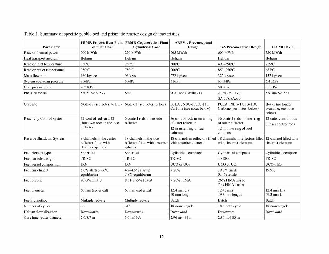
Table 1. Summary of specific pebble bed and prismatic reactor design characteristics.
Parameter PBMR Process Heat Plant
Annular Core PBMR Cogeneration Plant
Cylindrical Core AREVA Preconceptual
Design GA Preconceptual Design GA MHTGR
Reactor thermal power 500 MWth 250 MWth 565 MWth 600 MWth 350 MWth
Heat transport medium Helium Helium Helium Helium Helium
Reactor inlet temperature 350ºC 250ºC 500ºC 490–590ºC 259ºC
Reactor outlet temperature 950ºC 750ºC 900ºC 850–950ºC 687ºC
Mass flow rate 160 kg/sec 96 kg/s 272 kg/sec 322 kg/sec 157 kg/sec
System operating pressure 9 MPa 6 MPa 5 MPa 6.4 MPa 6.4 MPa
Core pressure drop 202 KPa 58 KPa 55 KPa
Pressure Vessel SA-508/SA-533 Steel 9Cr-1Mo (Grade 91) 2-1/4 Cr—1Mo
SA 508/SA533
SA 508/SA 533
Graphite NGB-18 (see notes, below) NGB-18 (see notes, below) PCEA , NBG-17, IG-110, Carbone (see notes below)
PCEA , NBG-17, IG-110, Carbone (see notes, below)
H-451 (no longer available, see notes below)
Reactivity Control System 12 control rods and 12 shutdown rods in the side reflector
6 control rods in the side reflector
36 control rods in inner ring of outer reflector
12 in inner ring of fuel columns
36 control rods in inner ring of outer reflector
12 in inner ring of fuel columns
12 outer control rods
6 inner control rods
Reserve Shutdown System 8 channels in the center reflector filled with absorber spheres
18 channels in the side reflector filled with absorber spheres
18 channels in reflectors filled with absorber elements
18 channels in reflectors filled with absorber elements
12 channel filled with absorber elements
Fuel element type Spherical Spherical Cylindrical compacts Cylindrical compacts Cylindrical compacts
Fuel particle design TRISO TRISO TRISO TRISO TRISO
Fuel kernel composition UO2 UO2 UCO or UO2 UCO or UO2 UCO-ThO2
Fuel enrichment 5.0% startup 9.6% equilibrium
4.2–4.5% startup 7.8% equilibrium
< 20% 19.8% fissile 0.7 % fertile
19.9%
Fuel burnup 90 GWd/mt U 8.31-8.75% FIMA < 20% FIMA 26% FIMA fissile 7 % FIMA fertile
Fuel diameter 60 mm (spherical) 60 mm (spherical) 12.4 mm dia 50 mm long
12.45 mm 49.3 mm length
12.4 mm Dia 49.3 mm L
Fueling method Multiple recycle Multiple recycle Batch Batch Batch
Number of cycles ~6 ~15 18 month cycle 18 month cycle 18 month cycle
Helium flow direction Downwards Downwards Downward Downward Downward
Core inner/outer diameter 2.0/3.7 m 3.0 m/N/A 2.96 m/4.84 m 2.96 m/4.83 m
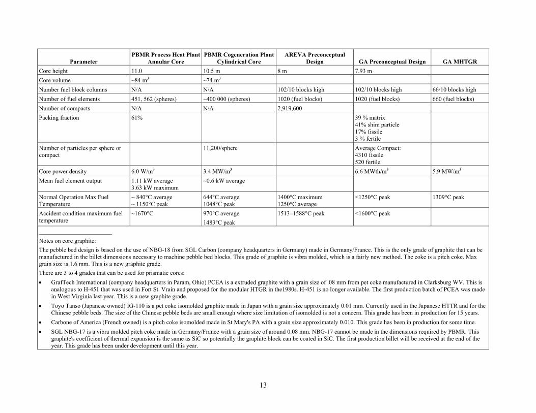
13
Parameter PBMR Process Heat Plant
Annular Core PBMR Cogeneration Plant
Cylindrical Core AREVA Preconceptual
Design GA Preconceptual Design GA MHTGR
Core height 11.0 10.5 m 8 m 7.93 m
Core volume ~84 m3 ~74 m3
Number fuel block columns N/A N/A 102/10 blocks high 102/10 blocks high 66/10 blocks high
Number of fuel elements 451, 562 (spheres) ~400 000 (spheres) 1020 (fuel blocks) 1020 (fuel blocks) 660 (fuel blocks)
Number of compacts N/A N/A 2,919,600
Packing fraction 61% 39 % matrix 41% shim particle 17% fissile 3 % fertile
Number of particles per sphere or compact
11,200/sphere Average Compact: 4310 fissile 520 fertile
Core power density 6.0 W/m3 3.4 MW/m3 6.6 MWth/m3 5.9 MW/m3
Mean fuel element output 1.11 kW average 3.63 kW maximum
~0.6 kW average
Normal Operation Max Fuel Temperature
~ 840°C average ~ 1150°C peak
644°C average 1048°C peak
1400°C maximum 1250°C average
<1250°C peak 1309°C peak
Accident condition maximum fuel temperature
~1670°C 970°C average
1483°C peak
1513–1588°C peak <1600°C peak
Notes on core graphite:
The pebble bed design is based on the use of NBG-18 from SGL Carbon (company headquarters in Germany) made in Germany/France. This is the only grade of graphite that can be manufactured in the billet dimensions necessary to machine pebble bed blocks. This grade of graphite is vibra molded, which is a fairly new method. The coke is a pitch coke. Max grain size is 1.6 mm. This is a new graphite grade.
There are 3 to 4 grades that can be used for prismatic cores:
GrafTech International (company headquarters in Param, Ohio) PCEA is a extruded graphite with a grain size of .08 mm from pet coke manufactured in Clarksburg WV. This is analogous to H-451 that was used in Fort St. Vrain and proposed for the modular HTGR in the1980s. H-451 is no longer available. The first production batch of PCEA was made in West Virginia last year. This is a new graphite grade.
Toyo Tanso (Japanese owned) IG-110 is a pet coke isomolded graphite made in Japan with a grain size approximately 0.01 mm. Currently used in the Japanese HTTR and for the Chinese pebble beds. The size of the Chinese pebble beds are small enough where size limitation of isomolded is not a concern. This grade has been in production for 15 years.
Carbone of America (French owned) is a pitch coke isomolded made in St Mary's PA with a grain size approximately 0.010. This grade has been in production for some time.
SGL NBG-17 is a vibra molded pitch coke made in Germany/France with a grain size of around 0.08 mm. NBG-17 cannot be made in the dimensions required by PBMR. This graphite's coefficient of thermal expansion is the same as SiC so potentially the graphite block can be coated in SiC. The first production billet will be received at the end of the year. This grade has been under development until this year.

14
3. COMPARISON OF REACTOR CONCEPTS
3.1 Comparing Configuration, Thermal Rating and Operating Conditions
The NGNP Project and the HTGR suppliers have defined a viable and large market for the application of HTGR technology in a wide range of industrial processes.10 These include: petrochemical, refining, chemical and fertilizer plants, bitumen recovery and upgrading from oil sands, oil shale recovery, coal and natural gas to liquid transportation fuel conversion, ammonia and ammonia derivative production, etc. All of these applications require a supply of energy at different ratings and in several forms, including steam, electricity, high temperature gas, hydrogen, and oxygen. The development of specific applications have identified required plant thermal ratings from 600 MWth to over 6000 MWth comprised of multiple HTGR modules. These applications also have varying requirements for availability; most approaching 100%. The modular nature of the HTGR technology and wide range of module size and plant configurations conceptualized in the NGNP Project provide flexibility to select a mix of module ratings and plant configurations that optimize the application of the technology to each process. Plant designs have also been conceptualized to provide all forms of energy required using either reactor concept.
The work performed thus far demonstrates that there is no one rating or configuration of the plant that fits all potential end uses of the HTGR technology. To ensure effective commercialization of this technology, flexibility is required in selecting each module rating and configuration. Such flexibility is available in both the pebble bed and prismatic reactor based designs conceptualized in the NGNP Project to-date. There is no distinguishing factor in this category that would favor one concept over the other.
Table 2 primarily compares the noncore design attributes of each of the parameters summarized for the pebble bed and prismatic reactor designs from Table 1. The core design attributes of both designs are then summarized in the following section and Table 3. The comparison concludes that although there are distinguishing characteristics between the two design concepts, none of them are factors that would favor selection of one concept over the other at this stage in the development of HTGR technology.
3.2 Comparing Core Designs
Table 3 presents a comparison similar to that in Table 2 for core design parameters. This table summarizes general differences and the impacts of those differences on the expected performance of the two reactor designs.
None of the phenomena described above, either individually or in the aggregate, tilt the balance significantly toward the pebble bed reactor or the prismatic reactor. They simply represent factors which must be accounted for in design and safety analyses.
15
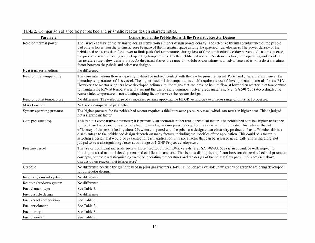
Table 2. Comparison of specific pebble bed and prismatic reactor design characteristics. Parameter Comparison of the Pebble Bed with the Prismatic Reactor Designs
Reactor thermal power The larger capacity of the prismatic design stems from a higher design power density. The effective thermal conductance of the pebble bed core is lower than the prismatic core because of the interstitial space among the spherical fuel elements. The power density of the pebble bed reactor is therefore lower to limit peak fuel temperatures during loss of flow conduction cooldown events. As a consequence, the prismatic reactor has higher fuel operating temperatures than the pebble bed reactor. As shown below, both operating and accident temperatures are below design limits. As discussed above, the range of module power ratings is an advantage and is not a discriminating factor between the pebble and prismatic designs.
Heat transport medium No difference.
Reactor inlet temperature The core inlet helium flow is typically in direct or indirect contact with the reactor pressure vessel (RPV) and , therefore, influences the operating temperatures of this vessel. The higher reactor inlet temperatures could require the use of developmental materials for the RPV, However, the reactor suppliers have developed helium circuit designs that can provide helium flow at lower than reactor inlet temperature to maintain the RPV at temperatures that permit the use of more common nuclear grade materials, (e.g., SA 508/533) Accordingly, the reactor inlet temperature is not a distinguishing factor between the reactor designs.
Reactor outlet temperature No difference. The wide range of capabilities permits applying the HTGR technology to a wider range of industrial processes.
Mass flow rate N/A not a comparative parameter.
System operating pressure The higher pressure for the pebble bed reactor requires a thicker reactor pressure vessel, which can result in higher cost. This is judged not a significant factor.
Core pressure drop This is not a comparative parameter; it is primarily an economic rather than a technical factor. The pebble bed core has higher resistance to flow than the prismatic reactor core leading to a higher core pressure drop for the same helium flow rate. This reduces the net efficiency of the pebble bed by about 2% when compared with the prismatic design on an electricity production basis. Whether this is a disadvantage to the pebble bed design depends on many factors, including the specifics of the application. This could be a factor in selecting a design that would be evaluated for each application. It is not a factor that can be assessed generically and is therefore, not judged to be a distinguishing factor at this stage of NGNP Project development.
Pressure vessel The use of traditional materials such as those used for current LWR vessels (e.g., SA-508/SA-533) is an advantage with respect to limiting required material development and codification and cost. This is not a distinguishing factor between the pebble bed and prismatic concepts, but more a distinguishing factor on operating temperatures and the design of the helium flow path in the core (see above discussion on reactor inlet temperature)..
Graphite No difference because the graphite used in prior gas reactors (H-451) is no longer available, new grades of graphite are being developed for all reactor designs.
Reactivity control system No difference.
Reserve shutdown system No difference.
Fuel element type See Table 3.
Fuel particle design No difference.
Fuel kernel composition See Table 3.
Fuel enrichment See Table 3.
Fuel burnup See Table 3.
Fuel diameter See Table 3.

16
Parameter Comparison of the Pebble Bed with the Prismatic Reactor Designs
Fueling method The continuous refueling of the pebble bed reactor could support a higher capacity factor than for the batch refueled prismatic reactor. The experience with the continuous refueling at AVR was good after correcting early operating problems. However, whether the balance of plant and other components within the nuclear heat supply can operate for the extended periods necessary to achieve the higher capacity factors (~95%) that would present an advantage for the pebble bed design has not been demonstrated. This is not judged to be a factor that can be quantified with confidence at this stage in the NGNP Project development and is therefore, not judged a viable distinguishing factor.
Number of cycles N/A to comparison.
Helium flow direction No difference.
Core inner/outer diameter N/A to comparison.
Core height The pebble bed configuration permits use of a longer active core. This is not a significant distinguishing factor.
Core volume N/A to comparison.
Number fuel block columns N/A to comparison.
Number of fuel elements This is not a distinguishing parameter; this parameter and the design of the fuel elements are primarily related to proliferation resistance. Past discussions of the difference in fuel element configurations have posited that the fuel block configuration may be less susceptible to diversion than the spheres.11 It is noted, however, that the composition of either fuel element, (embedment of the small fuel kernels in multiple layers of graphite) would not be an easy configuration for conversion for other uses. Proliferation of either fuel element configuration is not judged to be distinguishing factor.
Number of compacts N/A to comparison.
Packing fraction Related to fuel design and power density. See discussions on fuel design and reactor power.
Number of particles per sphere or compact
Related to fuel design and power density. See discussions on fuel design and reactor power.
Core power density See discussion on reactor power.
Mean fuel element output Related to fuel design and power density. See discussions on fuel design and reactor power.
Normal operation max fuel temperature
The prismatic reactor has higher operating fuel temperatures than the pebble bed reactor because of its higher power density. The operating temperatures for both designs are well within the design limits established from the fuel qualification programs. See discussions on reactor power and fuel design. This is not a significant distinguishing factor.
Accident condition maximum fuel temperature
The prismatic reactor has lower accident fuel temperatures than the pebble bed reactor because of the better conductance of the prismatic fuel blocks under loss of flow conduction cooldown events. The accident fuel temperatures for both designs are well within the design limits established from the fuel qualification programs. See discussions on reactor power and fuel design. This is not a significant distinguishing factor.

17
Table 3. Pebble bed reactor vs. prismatic-block reactor—a summary of differences. Item Difference and Impact
Fuel
Kernel composition Prismatic fuel is higher in packing fraction and enrichment to support batch refueling. Pebble bed reactor (PBR) fuel is UO2 enriched to 7–10% and is typically burned to about 90–100 GWD/tU. Prismatic modular reactor (PMR) fuel is UCO enriched to 10–20% low-enriched uranium (LEU) and is burned to about 120–190 GWD/tU. All other factors being equal, the power density, peak radiation damage, and temperature in the compacts are relatively higher than in the pebble. This is compounded by the fact that prismatic blocks do not move during operation so one set of compacts always sits in the region of high power density or high temperature. In the PBR, the fuel gets stirred and time at temperature effects are diminished.
Packing fraction
Enrichment/burnup
Core Thermal Fluid Transport
Pressure drop For the same core height and diameter, the pressure drop across a PBR core is much higher than in a PMR core. The pumping power to drive the primary coolant is comparably higher in the PBR (~8% of thermal power) than in the PMR (~2% of thermal power).
Coolant flow The design of the engineered cooling channels in prismatic blocks can be optimized to enhance heat extraction from the compacts. On the downside, the flow in individual flow channels can become unbalanced and lead to unacceptable local temperature peaking. Furthermore, under low flow conditions (such as after a loss of forced cooling), higher temperatures can lead to flow instability in hot channels. The temperature rise in a prismatic core is limited to about 400C to avoid this problem.
Convective Heat Transfer The tortuous path around pebbles, which causes the high pressure drop, also results in enhanced cooling geometry. All other things being equal, heat is pulled off the surface of pebble bed fuel more efficiently, resulting in lower fuel temperatures.
Nonconvective Heat Transfer
During a loss of forced cooling, radiation and conduction are the primary heat removal mechanisms. The larger contact surface between compacts and blocks facilitates conduction. Because of the small contact area between pebbles, radiative heat transfer between them is as important as conduction. Radiative heat transfer in the PBR exceeds conductive heat transfer at temperatures above about 1200C. The larger mass of graphite in the PMR also absorbs more decay heat after shutdown. The PMR can thus operate with a higher power density while keeping its fuel temperatures under 1600C after a loss of forced cooling.
Core Neutronics and Fuel Management
Refueling Refueling is essentially continuous in the PBR, making higher capacity factors possible. Circulation of the pebbles also allows the periodic inspection and assay of the fuel before it is discharged. The pebble fuel handling system (FHS) is completely different from the block handling machine of a PMR. The PBR FHS uses pneumatic transfer, charge and discharge chutes, singularizers, etc., to move pebbles automatically between the core and storage tanks. The PMR uses a block handling device to unload, load, and shuffle fuel elements at each outage. The process is somewhat more complicated than in an LWR in that the blocks in a column cannot be pulled out together. The core must be unloaded and reloaded layer-by-layer, column-by-column. Still, individual placement of blocks enables batch optimization and the potential to reduce uncertainty in power peaking and burnup.
Excess reactivity Online refueling enables the PBR to operate with very little excess reactivity (~1.3% ∆k), usually just enough to override xenon after an unplanned shutdown. Like an LWR, a PMR requires high fissile loading and burnable poisons to hold down the resulting reactivity in order to last through the cycle. The higher excess reactivity (~4.8% ∆k) also exacerbates reactivity transients, such as steam ingress, so that transient power peaks can be more severe.

18
Item Difference and Impact
Peaking Fuel design in blocks leads to significant power peaking, particularly at the core-reflector interface. PMR designers overcome this with a combination of burnable poisons, multiple zoned enrichments or packing fractions, or multiple particle types. With burnable poisons, peaking is limited to about 1.3 to 1.6 (maximum/average). PBR cores also exhibit radial peaking, but to a much lesser extent such that a single and homogeneous pebble fuel type is sufficient (~1.8 to 2.2). Random loading and recirculation in the PBR allows for the small and computable possibility of the formation of hotspots formed by two or more low-burnup pebbles in close proximity.
Analysis PMR fuel blocks are relatively heterogeneous compared to pebble fuel. Burnable poisons and off-center control rods challenge existing core simulation tools. Precise power peaking and local depletion calculations are difficult. The pebble bed is simpler from a lattice physics perspective, but there is an inherent uncertainty in power peaking calculations because the precise location of fuel elements cannot be computed.
Graphite Dimensional changes in the graphite blocks of both reactor concepts can distort control rod channels and degrade the cooling geometry of the fuel. Severe dimensional changes in the PMR may lead to difficulty in removing or shuffling fuel blocks. Gaps between fuel blocks will reduce cooling in the engineered cooling channels and increase compact temperatures in the blocks. Bypass flow can exacerbate the already higher stresses on the compacts.
Gaps are not an issue in the PBR core but bypass of coolant through the reflector blocks can be significant, so much so that the PBMR company had to design special keyed blocks to hold them together over their long life in the vessel. PBR blocks are expected to stay in the core for years, even decades, and thus be subjected to severe dimensional changes caused by exposure to the neutron flux. Reflector bypass flow is estimated to be as high as 15%. In the PMR, distorted reflector blocks can be removed during a given outage. The reflector bypass flow can therefore be kept under control.
Instrumentation and Control The engineered and stationary cooling channels of the PMR can be used for low-power physics testing (insertion of thermocouples, flux wires, etc.). Locating in-core instrumentation in the PBR is difficult.
Neutron absorbers cannot be easily inserted into the PBR (although in-core control rods were used in the thorium HTR with, not surprisingly, some fuel damage). Control rods and absorber spheres must be inserted into the reflectors.
In both concepts, flux and temperature during operation are inferred from ex-core measurements. This is a typical arrangement in nuclear power plants and not a distinguishing factor for either reactor design.
Source Term (including dust) The abrasive action of moving pebbles leads to the generation of carbonaceous dust in the PBR primary loops, probably on the order of kilograms per year. This dust can be a carrier for fission product transport during some depressurization accidents.
On the other hand, the higher power peaking, temperatures, and temperature gradients of the PMR core result in higher release rates from the fuel and a somewhat higher probability of particle failure.
Accident Sequence Not much difference except that the PBR core can be subjected to seismically-induced settling that results in a subsequent reactivity insertion. The amount of reactivity inserted is lower than other anticipated transient initiators.
Power Output Because control rods in the PBR must be located in the reflector and the (usually) lower heat conductivity of pebbles during a conduction cooldown event, the thermal power output of a PBR is limited to 400 to 500 MW. PMRs can be designed with a power output of 600 MW, perhaps higher.
Proliferation Continuous fueling the small size of pebbles offers a greater opportunity for illicit diversion of nuclear material. Conversely, the relatively high excess reactivity required of PMR batch refueling can mask irradiation of fertile material for illicit weapons production.
The amount and quality of fissile plutonium, per MWD of energy produced, found in the spent fuel of either NGNP concept is lower than that of LWRs.
As noted above, past discussions of the difference in fuel element configurations have posited that the fuel block configuration may be less susceptible to diversion than the spheres.12 It is noted, however, that the composition of either fuel element, (embedment of the small fuel kernels in multiple layers of graphite) would not be an easy configuration for conversion for other uses. Proliferation of either fuel element configuration is not judged to be distinguishing factor.
19
4. R&D REQUIRED TO SUPPORT DESIGN AND LICENSING ACTIVITIES
4.1 Fuel Development and Qualification
The Fuel Development and Qualification Program12 will qualify TRISO-coated particle fuel for use in NGNP. TRISO-coated particles will be fabricated at pilot scale for use in the formal qualification testing. The testing program consists of irradiations, safety testing and postirradiation examinations that will characterize the behavior of TRISO-coated fuel under both normal and off-normal conditions. The program also contains out-of-pile experiments, special irradiations and safety testing to characterize the release and transport of fission products from the kernel, through the coatings, the fuel matrix, the graphite and the primary system (i.e., source term). Formal validation testing is also planned to validate fuel performance and fission product models, required for core performance assessments and safety analysis. The program is currently considering both UCO and UO2. Once a design decision is reached by the NGNP Project, the program will focus on either UCO for prismatic or UO2 for pebble bed. A detailed discussion of fuel and source term qualification for both pebble bed and prismatic technologies was recently provided to the NRC in a white paper.13,14
A fuel acquisition strategy, established in 2007,15 provided a detailed technical assessment of potential fuel vendors for the first core of NGNP, conducted by an independent group of international experts based on input from the three major reactor vendor teams. Part of the assessment included an evaluation of the credibility of each option, along with a cost and schedule to implement each strategy compared with the schedule and throughput needs of the NGNP Project. While credible options were identified, many changes in the assumptions underlying the strategy and in externalities that have happened in the interim require that the options be reevaluated once the preliminary design activities in Phase II are underway.
A detailed resource-loaded activity-based schedule for the activities presented in the technical program plan for TRISO fuel has been developed and is used to guide and prioritize activities year by year. The critical path for the fuel qualification is through the irradiations early in the program and then shifts to the postirradiation examination and safety testing later in the program. Based on the schedule, the fuel for NGNP is anticipated to be qualified by mid-2022 assuming the funding levels required to accomplish the tasks is made available.
4.2 Graphite Development and Qualification
The objective of the NGNP Graphite Program16 is to develop the qualification data set of thermomechanical and thermophysical properties for unirradiated and irradiated candidate grades of graphite for NGNP. As part of the acquisition strategy for graphite, four major graphite grades from four vendors around the world (Graftec and Mersenin the U.S., SGL in Europe, and Toyo Tanso in Japan) suitable for use within both a pebble bed and prismatic HTGR design have been selected for further evaluation. Minor grades and historical samples have also been incorporated into the program to help further elucidate the impact of fabrication processes and coke sources on the resulting microstructure of the graphite and its performance under irradiation. Major grades include NBG-18 (SGL), PCEA (GrafTech Inc.), IG-110 (Toyo Tanso), and 2114 (Mersen, formerly known as Carbonne Lorraine) while minor grades include PGX, HLM, PCIB, NBG-17, IG-430, and others.
The program consists of statistical characterization of unirradiated graphite material properties to establish the lot-to-lot, billet-to-billet and within billet variability of the material. Irradiations are planned at specified temperatures and doses within the design service condition envelope anticipated for NGNP. Extensive post irradiation examinations are planned to establish the change in relevant material properties as a function of temperature and neutron dose. Of particular interest is the irradiation induced creep of

20
graphite, which is critical to determining the lifetime of the graphite under irradiation. From these datasets, constitutive relations will be established for use in a detailed predictive thermo-mechanical finite element model. These data will also support development of relevant ASTM standards and ASME design rules. In the longer term, the program plans to evaluate processing route and raw material constituent influences on graphite behavior so that additional large qualification irradiation programs are not needed when new coke sources are used to make graphite for HTGRs. A detailed discussion of graphite qualification was recently provided to the NRC in a white paper.17
A detailed resource-loaded activity-based schedule for the activities presented in the technical program plan for graphite has been developed and is used to guide and prioritize activities year by year. The critical path for graphite qualification is through the irradiations. Postirradiation characterization will be performed at INL and ORNL to complete the large number of characterization activities and not impact the critical path. Assuming the funding levels required to accomplish the tasks is made available, the schedule shows that the graphite for NGNP will be qualified by 2021.
4.3 High Temperature Materials
The goal of the NGNP High Temperature Materials Program.18,19 is to obtain the performance data required to support the development of these high temperature components and associated design codes over the broader range of envisioned outlet temperatures for HTGRs to support co-generation of steam and electricity at lower temperatures (750-800°C) and hydrogen production and hot gas delivery at higher temperatures (850-950°C) for a variety of end user applications. A number of solid-solution-strengthened, nickel-based alloys have been considered for application in heat exchangers and core internals for an HTGR. The primary candidates are Inconel 617, Haynes 230, Incoloy 800H, and Hastelloy X. Of these alloys, only Incoloy 800H is currently approved for high temperature design in the ASME Code and only up to 760°C. As the outlet temperature increases from 750°C to 950°C, the number of potential alloys decreases and the specific material issues change. Materials selection is based on the technical maturity, availability in required product forms, experience base, and mechanical properties at elevated temperatures. The materials under consideration are largely independent of the reactor configuration (pebble bed vs. prismatic).
Creep, creep-fatigue, aging, and environmental degradation testing is planned using the candidate high temperature material selected for NGNP. Thick and thin sections of base material, weldments and other joints (e.g. diffusion bonding) will be evaluated given the different design options under consideration for the IHX and steam generator. Depending on the outlet temperature selected by the NGNP Project, additional high temperature data may be needed to support relevant ASME code cases for the material. R&D to establish requisite in-service inspection techniques will be developed as key components are being designed. Prototype testing of key components is envisioned in a high temperature flow loop to characterize overall behavior under prototypic flowing HTGR conditions and validate ISI techniques. A detailed discussion of high temperature materials was recently provided to the NRC in a white paper.17
4.4 Design and Safety Methods Validation
The goals of the Design and Safety Methods Validation Program for NGNP are to develop validation experiments and data to validate models and analytical tools for NGNP, to resolve key safety, performance, and technical issues through confirmatory modeling and/or tool development when existing models and/or tools are judged to be inconclusive or inadequate, and to modify, upgrade, and/or develop new analytical tools for future use that will reduce uncertainties and improve the capability of understanding the behavior and operating margins of the plant. Current areas of focus include developing improved differential cross-sections for Pu isotopes to reduce uncertainties in the reactivity performance of high burnup LEU HTGR cores, assessing and improving reactor physics and kinetic methods for prismatic and pebble bed HTGRs, performing physics benchmark studies on past relevant experiments,

21
evaluating important phenomena that influence thermal-fluid behavior in both pebbled bed and prismatic HTGRs and establishing relevant experiments for V&V, evaluating of air-ingress phenomena in HTGRs and participating in relevant validation experiments, developing experiments to validate reactor cavity cooling system behavior, and evaluating and establishing system level codes appropriate for HTGR safety analysis. The program currently includes activities that support both pebble bed and prismatic technologies.
Based on the review of the planned R&D activities, there are no distinguishing factors that favor one design over the other.

22
5. TECHNOLOGY DEVELOPMENT REQUIRED TO COMPLETE DESIGN EFFORT AND TO SUPPORT LICENSING OF THE REACTOR
CONCEPT BY THE NRC
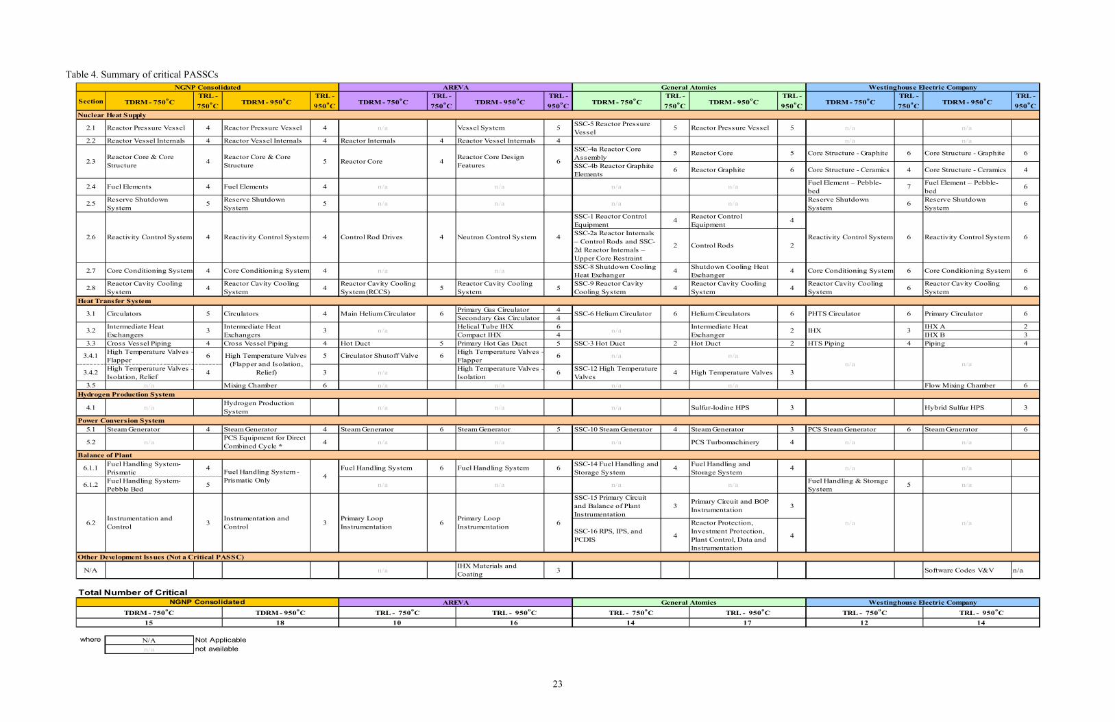
The NGNP Project Risk Management Plan20 has developed and implemented a technology development roadmap (TDRM) process that (1) establishes the technology readiness level (TRL) of each criticala plant area, system, subsystem and component (PASSC), and (2) develops the necessary effort to achieve the TRL required to have confidence in the performance of the PASSC when installed in the plant. The development of design data needs during the preconceptual design work in FY 2007 and refinement of these in FY 2008 and FY 2009 combined with development of the TDRM for the HTGR in this time frame identified the following areas listed in Table 1as specific areas requiring technical development, both generically and design specific (as shown by supplier in the table). The TDRM defines the specific efforts required to progress the TRL of the areas summarized in Table 6. The TRL of every developmental component, the status of the necessary work scope to advance TRLs, and the summary tables are maintained by the Risk Management Program in coordination with the supplier teams.
Although Table 6 identifies specific development efforts required by the reactor type, close examination of the table will reveal that the fundamental development requirements are generic across all reactor designs. There is no clear distinguishing characteristic or developmental requirement in any of the designs proposed to-date in the NGNP Project that favors one design over the other. This supports continuing with development of both PBR and PMR design concepts.
a. Critical PASSCs are defined as those components that are not commercially available or have not been proven in relevant
industry environments, at appropriate scale, or fully integrated with other components.
23
Table 4. Summary of critical PASSCs
Section TDRM - 750oC
TRL -
750oC
TDRM - 950oC
TRL -
950oC
TDRM - 750oC
TRL -
750oC
TDRM - 950oC
TRL -
950oC
TDRM - 750oC
TRL -
750oC
TDRM - 950oC
TRL -
950oC
TDRM - 750oC
TRL -
750oC
TDRM - 950oC
TRL -
950oC
2.1 Reactor Pressure Vessel 4 Reactor Pressure Vessel 4 n/a Vessel System 5SSC-5 Reactor Pressure Vessel
5 Reactor Pressure Vessel 5 n/a n/a
2.2 Reactor Vessel Internals 4 Reactor Vessel Internals 4 Reactor Internals 4 Reactor Vessel Internals 4 n/a n/aSSC-4a Reactor Core Assembly
5 Reactor Core 5 Core Structure - Graphite 6 Core Structure - Graphite 6
SSC-4b Reactor Graphite Elements
6 Reactor Graphite 6 Core Structure - Ceramics 4 Core Structure - Ceramics 4
2.4 Fuel Elements 4 Fuel Elements 4 n/a n/a n/a n/aFuel Element – Pebble-bed
7Fuel Element – Pebble-bed
6
2.5Reserve Shutdown System
5Reserve Shutdown System
5 n/a n/a n/a n/aReserve Shutdown System
6Reserve Shutdown System
6
SSC-1 Reactor Control Equipment
4Reactor Control Equipment
4
SSC-2a Reactor Internals – Control Rods and SSC-2d Reactor Internals – Upper Core Restraint
2 Control Rods 2
2.7 Core Conditioning System 4 Core Conditioning System 4 n/a n/aSSC-8 Shutdown Cooling Heat Exchanger
4Shutdown Cooling Heat Exchanger
4 Core Conditioning System 6 Core Conditioning System 6
2.8Reactor Cavity Cooling System
4Reactor Cavity Cooling System
4Reactor Cavity Cooling System (RCCS)
5Reactor Cavity Cooling System
5SSC-9 Reactor Cavity Cooling System
4Reactor Cavity Cooling System
4Reactor Cavity Cooling System
6Reactor Cavity Cooling System
6
Primary Gas Circulator 4Secondary Gas Circulator 4Helical Tube IHX 6 IHX A 2Compact IHX 4 IHX B 3
3.3 Cross Vessel Piping 4 Cross Vessel Piping 4 Hot Duct 5 Primary Hot Gas Duct 5 SSC-3 Hot Duct 2 Hot Duct 2 HTS Piping 4 Piping 4
3.4.1High Temperature Valves - Flapper
6 5 Circulator Shutoff Valve 6High Temperature Valves - Flapper
6 n/a n/a
3.4.2High Temperature Valves - Isolation, Relief
4 3 n/aHigh Temperature Valves - Isolation
6SSC-12 High Temperature Valves
4 High Temperature Valves 3
3.5 n/a Mixing Chamber 6 n/a n/a n/a n/a Flow Mixing Chamber 6
4.1 n/aHydrogen Production System
n/a n/a n/a Sulfur-Iodine HPS 3 Hybrid Sulfur HPS 3
5.1 Steam Generator 4 Steam Generator 4 Steam Generator 6 Steam Generator 5 SSC-10 Steam Generator 4 Steam Generator 3 PCS Steam Generator 6 Steam Generator 6
5.2 n/aPCS Equipment for Direct Combined Cycle *
4 n/a n/a n/a PCS Turbomachinery 4 n/a n/a
6.1.1Fuel Handling System-Prismatic
4 Fuel Handling System 6 Fuel Handling System 6SSC-14 Fuel Handling and Storage System
4Fuel Handling and Storage System
4 n/a n/a
6.1.2Fuel Handling System-Pebble Bed
5 n/a n/a n/a n/aFuel Handling & Storage System
5 n/a
SSC-15 Primary Circuit and Balance of Plant Instrumentation
3Primary Circuit and BOP Instrumentation
3
SSC-16 RPS, IPS, and PCDIS
4
Reactor Protection, Investment Protection, Plant Control, Data and Instrumentation
4
N/A n/aIHX Materials and Coating
3 Software Codes V&V n/a
where N/A Not Applicable
n/a not available
14
NGNP Consolidated
TDRM - 750oC
15
TRL - 950oC TRL - 750
oC TRL - 950
oC
18 10 16 14 17 12
6.2
TDRM - 950oC TRL - 750
oC TRL - 950
oC TRL - 750
oC
AREVA General Atomics Westinghouse Electric Company
66 n/a
6
66
6
Primary Circulator
4
Reactivity Control System
2
6
4
4
n/a
4
NGNP Consolidated AREVA
42.6 Reactivity Control System Control Rod Drives Neutron Control System
General Atomics Westinghouse Electric Company
4 5 4
3
Reactivity Control System
5 6Main Helium Circulator
Instrumentation and Control
Primary Loop Instrumentation
n/aPrimary Loop Instrumentation
3
33.2Intermediate Heat Exchangers
Intermediate Heat Exchanger
n/a
n/a3
4
2.3Reactor Core & Core Structure
Reactor Core Reactor Core Design Features
3.1 Circulators
3IHX
n/a
SSC-6 Helium Circulator Helium Circulators PHTS CirculatorCirculators
Intermediate Heat Exchangers
Instrumentation and Control
Fuel Handling System - Prismatic Only
6
6
Nuclear Heat Supply
Heat Transfer System
Hydrogen Production System
Power Conversion System
Balance of Plant
High Temperature Valves (Flapper and Isolation,
Relief)
Reactor Core & Core Structure
Reactivity Control System
Total Number of Critical
Other Development Issues (Not a Critical PASSC)
24
6. CONCLUSION
6.1 General
This comparison concludes that there is no technical basis at the time of this writing for down-selecting a reactor design—pebble bed or prismatic—for further development in completing of the NGNP Project. This conclusion is based on detailed comparison of the status of the design and development of both of these reactor designs in the following areas:
Configuration, thermal rating, and operating conditions, which includes comparison of over 30 specific design characteristics of two pebble bed reactor configurations and four prismatic reactor configurations that have been conceptualized as part of work completed thus far in the NGNP Project.
Technical viability to supply the several energy forms at the required conditions (e.g., thermal rating, temperature, pressure) needed to supply the energy needs of the wide range of industrial processes identified thus far by the NGNP Project as candidates for the HTGR technology application. This review included evaluation and assessment of advantages of one design over the other in the following areas:
- Fuel composition, packing fraction, enrichment and burnup
- Core thermal fluid transport, including pressure drop, coolant flow, convective heat transfer, nonconvective heat transfer
- Core neutronics and fuel management, including refueling, excess reactivity, power peaking, analysis
- Graphite
- Instrumentation and control
- Source term (including dust)
- Accident sequence
- Power output
- Proliferation.
R&D required to support design and licensing activities, including review of the objectives and coverage of the R&D requirements of both reactor designs, including the Fuel Development and Qualification Program, Graphite Development and Qualification Program, High Temperature Materials Qualification Program, and the Methods Validation Program.
Technology development required to complete design efforts and to support licensing of the reactor concept by the NRC. This comparison examined the summary of the design development needs identified in the NGNP Project for each reactor design in the TDRMs prepared as part of the NGNP Project Risk Management Plan.
This assessment did not compare plant capital, operating costs, lifetime, and other factors affecting the economic viability of the designs. This was not included in this assessment for the following reasons:
None of these are developed for either reactor design at the time of this writing to the level of confidence required to make a viable assessment of one design versus the other. Completion of the full conceptual design effort is required of both designs to provide enough confidence in the estimate of capital and operating costs, plant lifetime, projected availability, and other factors that need to be considered in this assessment.
These may not be significant factors in the selection of either the pebble bed or the prismatic reactor design for a specific application. The selection of the type of reactor, the module ratings, the number of modules, the configuration of the balance of plant, and a myriad of other design selections will be made on the basis of optimizing the business case for the application. These are not decisions that can

25
be made on a generic basis with any confidence within a project that has the objective of commercializing a technology, not a specific design particularly at an early stage in the NGNP Project.
It is the judgment of the NGNP Project that throughout the design and licensing process no differentiating technical factors will be identified that justify selection of one reactor design (i.e., pebble bed or prismatic) over the other. It is anticipated that the selection of reactor design will be made by the future owner of the plant based on specific licensing basis requirements and the business case.

26
7. REFERENCES 1. NGNP Alliance, “Implementation Strategy for the Next Generation Nuclear Plant Project,” Letter
Report, November 30, 2009.
2. Public Law 109-58, “Energy Policy Act of 2005,” 109th Congress, August 8, 2005
3. DOE, “Financial Assistance Funding Opportunity Announcement, Next Generation Nuclear Plant Program—Gas Cooled Reactor Design and Demonstration Projects,” DE-FOA-0000149, September 18, 2009.
4. George Honma, NGNP Fuel Qualification White Paper, INL/EXT-10-17686, Idaho National Laboratory, July 21, 2010.
5. Wayne Moe, Mechanistic Source Terms White Paper, INL/EXT-10-17997, Idaho National Laboratory, July 27, 2010.
6. Phil Mills, Doug Vandel, Sam Bader, Larry Demick, and Vondell Balls, Next Generation Nuclear Plant Pre-conceptual Design Report, INL/EXT-07-12967, Idaho National Laboratory, September 19, 2007.
7. Steve Melancon, Entergy, “Next Generation Nuclear Plant Project Senior Advisory Group Meeting and Alliance Working Meeting,” September 24, 2008.
8. Steve Melancon, Entergy, “Next Generation Nuclear Plant Project Senior Advisory Group Meeting Reference Configuration,” October 28, 2008.
9. Steve Melancon, Entergy, “Next Generation Nuclear Plant Project Senior Advisory Group Meeting and Alliance Working Meeting,” July 30, 2009.
10. Mike Patterson, Integration of High-Temperature Gas-cooled Reactors into Industrial Process Applications, INL/EXT-09-16942, Idaho National Laboratory, February 10, 2010.
11. Kevan Weaver, NGNP Engineering White Paper: Reactor Type Trade Study, INL/EXT-07-12729, Idaho National Laboratory, April 1, 2007.
12. Petti, David, Richard Hobbins, and James Kendall, 2008, Technical Program Plan for the Advanced Gas Reactor Fuel Development and Qualification Program, INL/EXT-05-00465, Revision 2, July 2008.
13. NGNP Fuel Qualification White Paper, INL/EXT-10-17686, July 2010.
14. Mechanistic Source Term White Paper, INL/EXT-10-17997, July 2010
15. David Petti, Tim Abram, Ben Franklin, Richard Hobbins and Jim Kendall, “Assessment of Next Generation Nuclear Plant (NGNP) Fuel Acquisition Strategies,” INL/EXT-07-12441, Rev 1, October 2007.
16. Windes, W., T. Burchell, R. Bratton, 2007, “Graphite Technology Development Plan,” PLN-2497, Rev 0, October 2007.
17. NGNP Materials White Paper, INL/EXT-09-17187, June 2010
18. “Next Generation Nuclear Plant Intermediate Heat Exchanger Materials Research and Development Plan,” Idaho National Laboratory PLN-2804, April 2008.
19. Wright, R. N., and J. K. Wright, “Next Generation Nuclear Plant Reactor Pressure Vessel Materials Research and Development Plan,” Idaho National Laboratory PLN-2803, Revision 1, 07/14/10.
20. John Collins, “Risk Management Plan for the Next Generation Nuclear Plant Project,” PLN-2347, Idaho National Laboratory, September 30, 2009.