technology development road mapping report for ngnp …
TRANSCRIPT

PC-000586Revision 0
ENGINEERING SERVICES FOR THE NEXT GENERATION NUCLEAR PLANT (NGNP) WITH
HYDROGEN PRODUCTION
Technology Development Road Mapping Report for NGNP with
750°C Reactor Outlet Helium Temperature
Prepared by General Atomics For the Battelle Energy Alliance, LLC
Subcontract No. 00075309 Uniform Filing Code UFC:8201.3.1.2
GA Project 30302
CM Aprvd
ISSUED2009/05/11


Technology Development Road Mapping Report for NGNP with 750°C Reactor Outlet Helium Temperature PC-000586/0
iii
LIST OF CONTRIBUTORS
Name Organization
John Saurwein General Atomics
Matt Richards General Atomics
David Carosella General Atomics
Amy Bozek General Atomics
Jessie Crozier General Atomics
Puja Gupta General Atomics
Carol Moseley General Atomics
John Bolin General Atomics
Stephen Gibson General Atomics
Russ Vollman General Atomics
HanKwon Choi Washington Division of URS Corp.
Bill McTigue Washington Division of URS Corp.
David Carroccia Washington Division of URS Corp
Greg Walz Washington Division of URS Corp
Gary Stark Washington Division of URS Corp
Cody Connell Washington Division of URS Corp

Technology Development Road Mapping Report for NGNP with 750°C Reactor Outlet Helium Temperature PC-000586/0
iv
EXECUTIVE SUMMARY
A decision was made by the NGNP Project in October 2008 to reduce the nominal reactor outlet helium temperature for the NGNP from 950°C into the range of 750°C to 800°C. This decision to reduce the reactor outlet helium temperature has a significant impact on the technology development effort required to support the NGNP. Specifically, much of the technology development required for an NGNP operating with a reactor outlet helium temperature of 950°C will no longer be needed (for example, development and qualification of high-temperature metal alloys for the IHX and ceramic composites for several reactor internals components, design and verification of a reactor vessel cooling system, etc.).
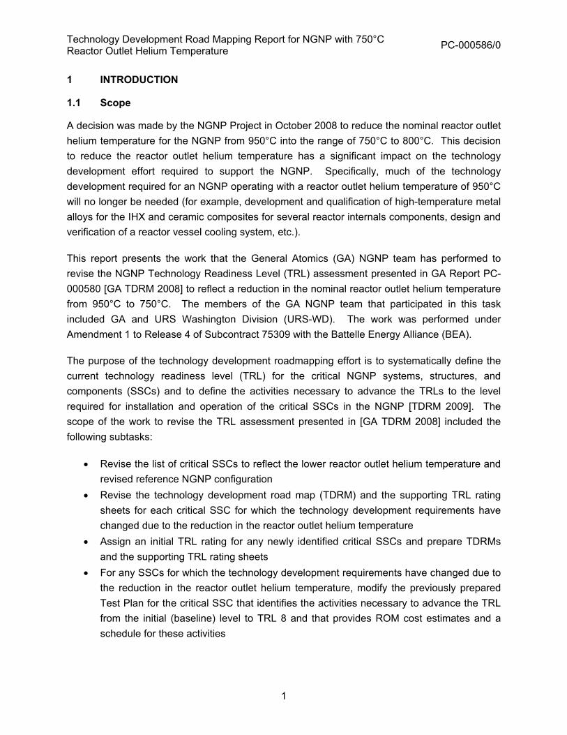
This report presents the work that the General Atomics (GA) NGNP team has performed to revise the NGNP Technology Readiness Level (TRL) assessment presented in GA Report PC-000580 to reflect a reduction in the nominal reactor outlet helium temperature from 950°C to 750°C. The Technology Development Road Maps (TDRMs) in PC-000580 and the corresponding Test Plans were developed in 2008 for the NGNP configuration shown in Figure E-1. Based on the decision by the NGNP Project to lower the reactor outlet helium temperature into the range 750°C - 800°C, GA has selected the configuration shown in Figure E-2 as its reference NGNP configuration, which will be the point of departure for NGNP conceptual design.
Figure E-1. NGNP Configuration for Technology Development Roadmapping in 2008

Technology Development Road Mapping Report for NGNP with 750°C Reactor Outlet Helium Temperature PC-000586/0
v
BOP PCS Side
Feedwater Heater(s)
Main Condenser
Power to the Grid
LP Turbine
Steam to Steam Process Heat Exchanger
Condensate Heater(s)
Generator
Condensate Pumps
Steam Generator
Feedwater Pumps
HP Turbine
322 C
Primary Helium
Circulator
540 C
200 C
NHSS PCS Side
Reactor
600 MWt
750 C
Figure E-2. Current NGNP Configuration for Technology Development Roadmapping It is currently anticipated that the NGNP will be used to co-generate electricity and process heat in the form of steam, and that the steam will be provided to the end-user’s facility via a tertiary loop. Heat will be transferred from an appropriate location (or locations) in the power conversion loop to the tertiary loop via a steam-to-steam heat exchanger. A steam-to-steam heat exchanger may also be needed in the power conversion loop to reheat the steam exiting the high pressure turbine as a means of improving power conversion cycle efficiency and reducing steam wetness at the back end of the cycle.
The purpose of the technology development roadmapping effort is to systematically define the current technology readiness level (TRL) for the critical systems, structures, and components (SSCs) and to define the activities necessary to advance the TRLs to the level required for installation and operation of the critical SSCs in the NGNP. The scope of the work to revise the TRL assessment presented in PC-000580 included the following subtasks:
� Revise the list of critical SSCs to reflect the lower reactor outlet helium temperature and revised reference NGNP configuration

Technology Development Road Mapping Report for NGNP with 750°C Reactor Outlet Helium Temperature PC-000586/0
vi
� Revise the technology development road map (TDRM) and the supporting TRL rating sheets for each critical SSC for which the technology development requirements have changed due to the reduction in the reactor outlet helium temperature
� Assign an initial TRL rating for any newly identified critical SSCs and prepare TDRMs and the supporting TRL rating sheets
� For any SSCs for which the technology development requirements have changed due to the reduction in the reactor outlet helium temperature, modify the previously prepared Test Plan for the critical SSC that identifies the activities necessary to advance the TRL from the initial (baseline) level to TRL 8 and that provides ROM cost estimates and a schedule for these activities
� Prepare an integrated technology development schedule that supports NGNP startup in 2021
� Prepare a final report that includes the TDRMs, the supporting TRL ratings sheets, and the integrated SSC test schedule
For the purposes of the technology road mapping task, critical SSCs are defined as SSCs that are not commercially available or that do not have proven industry experience. For the plant configuration shown in Figure E-2, GA has identified the following critical SSCs:
� Reactor control equipment � Control rods � Upper core restraint � High temperature ducting (hot duct) � Reactor core assembly � Reactor graphite elements � Reactor pressure vessel � Helium circulators (PHTS and SCS) � Shutdown cooling heat exchanger (SCHE) � Reactor cavity cooling system (RCCS) � Steam generator (SG) � High temperature valves � Fuel handling and storage system � Primary circuit and balance of plant instrumentation � RPS, IPS, and PCDIS � Fuel

Technology Development Road Mapping Report for NGNP with 750°C Reactor Outlet Helium Temperature PC-000586/0
vii
Table E-1 lists the initial TRL rating1 that GA has assigned to each critical SSC and shows how the critical SSCs and TRL ratings have changed relative to those in PC-000580.
Table E-1. Initial TRL Ratings for NGNP Critical SSC
Initial TRL Rating SSC # Critical SSC Figure E-1 Figure E-2
1 Reactor control equipment 4 4 2 Reactor internals a1. Control rods – composite 2 2 a2. Control rods – metallic NA* 4 b. Control rod and RSM guide tubes 2 4 c. Metallic core support structure (insulation) 3 3 d1. Upper core restraint - composite 2 2 d2. Upper core restraint - metallic NA 4 e. Upper plenum shroud (thermal barrier) 2 4
3 Hot duct 2 2 4 Reactor core and graphite
a. Reactor core 5 5 b. Graphite 6 6
5 Reactor pressure vessel 5 5 6 Helium circulator 6 6 7 Intermediate heat exchanger 2 NA 8 Shutdown cooling system heat exchanger 4 4 9 Reactor cavity cooling system 4 4 10 Steam Generator 3 4 11 Turbomachinery (for combined cycle PCS) 4 NA 12 High temp. isolation valves and pressure relief valves 3 4 13 S-I hydrogen production system 3 NA 14 Fuel handling and storage system 4 4 15 Primary circuit and BOP protection inst. 3 3 16 RPS, IPS, PCDIS 4 4 N/A Fuel 4 4
*NA = Not applicable
As indicated in Table E-1, three of the critical SSCs for the previous NGNP configuration shown in Figure E-1 are not critical SSCs for the new reference configuration shown in Figure E-2. These include the intermediate heat exchanger, the S-I hydrogen production system, and the turbomachine, none of which are needed for the new plant configuration. On the other hand, variations of two of the critical SSCs have been added. These include metallic control rods and 1 See Table 2-1 for TRL definitions

Technology Development Road Mapping Report for NGNP with 750°C Reactor Outlet Helium Temperature PC-000586/0
viii
metallic upper core restraint elements. These SSC variations were added because GA considers it likely that these components will have to be made initially from high-temperature metals while ceramic composite components are being developed and qualified as a future design improvement. This approach is considered necessary because it is considered unlikely that the ceramic composite components can be developed and qualified on a schedule that would make them available for an NGNP startup in 2021. However, It is anticipated that the parallel effort to develop ceramic composite control rods and upper core restraint elements will eventually lead to replacement of their metallic counterparts. Reflecting the need for less technology development for the metallic components, the initial TRL assigned to the metallic control rods and upper core restraint elements is 4 compared to 2 for the corresponding ceramic composite components.
With respect to changes in the initial TRL ratings, the initial TRL rating of the steam generator (3 to 4), the control rod and RSM guide tubes (2 to 4), and the upper plenum shroud (2 to 4) have been increased due to elimination of the need to develop and qualify high-temperature materials for these components. This is a direct benefit of the reduction in the reactor outlet helium temperature. Another component that is greatly impacted by the reduction in the reactor outlet helium temperature is the reactor pressure vessel because the lower reactor outlet temperature eliminates the need for a direct vessel cooling of the vessel. Although the initial TRL level assigned to the reactor pressure vessel was 5 for both the old and new reference NGNP configurations, the level of effort and cost associated with increasing the TRL from 5 to 8 is substantially reduced as a result of the reduction in the reactor outlet helium temperature.
As previously noted in PC-000580, because the NGNP design process is at a very early stage, adequate design details to precisely define design data needs (DDNS) and the testing required to satisfy the DDNs are not currently available. Consequently, the TDRMs, TRL rating sheets, and test plans reflect GA’s engineering judgment at this time based on the results of the NGNP preconceptual and conceptual design studies performed by the GA NGNP team and the design data needs (DDNs) and engineering development plans developed for other GA MHR designs, including the MHTGR, the NP-MHTGR, the GT-MHR, and the PC-MHR, none of which have the same reactor operating conditions as proposed in the current reference NGNP configuration. Consequently, GA views the TDRMs, TRL rating sheets, and test plans as preliminary documents that will need to be continually updated as the design and technology development efforts progress. Further, it is assumed that DDNs specific to the NGNP design will be prepared during NGNP conceptual design and that the specific requirements for the tests needed to satisfy the DDNs will be defined in Test Specifications, which will also be prepared by GA during conceptual design. The details of the tests will be provided in test plans and test procedures to be prepared by the testing organizations.

Technology Development Road Mapping Report for NGNP with 750°C Reactor Outlet Helium Temperature PC-000586/0
ix
TABLE OF CONTENTS
EXECUTIVE SUMMARY ............................................................................................................. ivACRONYMS ................................................................................................................................ xi1 INTRODUCTION............................................................................................................... 1
1.1 Scope..........................................................................................................................11.2 Reference NGNP Configuration.................................................................................. 31.3 Critical SSCs............................................................................................................... 5
2 METHODOLOGY.............................................................................................................. 82.1 Establish Baseline TRLs ............................................................................................. 82.2 Preparation of TDRMs and TRL Rating Sheets........................................................ 10
3 BASELINE TRL RATINGS............................................................................................. 134 TDRMS, TRL RATING SHEETS, AND TEST PLANS ................................................... 15
4.1 RC2-SSC-1 Reactor Control Equipment................................................................... 174.2 RC2-SSC-2a Control Rods and RC2-SSC-2d Upper Core Restraint ....................... 354.3 RC2-SSC-3 Hot Duct TRL ........................................................................................ 734.4 RC2-SSC-4a Reactor Core Assembly and RC2-SSC-4b Reactor Graphite Elements874.5 RC2-SSC-5 Reactor Pressure Vessel ...................................................................... 984.6 RC2-SSC-6 Helium Circulator ................................................................................ 1064.7 RC2-SSC-8 Shutdown Cooling Heat Exchanger .................................................... 1134.8 RC2-SSC-9 Reactor Cavity Cooling System .......................................................... 1214.9 RC2-SSC-10 Steam Generator............................................................................... 1284.10 RC2-SSC-12 High Temperature Valves.............................................................. 1354.11 RC2-SSC-14 Fuel Handling and Storage System............................................... 1454.12 RC2-SSC-15 Primary Circuit and Balance of Plant Instrumentation ................... 1564.13 RC2-SSC-16 RPS, IPS, and PCDIS ................................................................... 172
5 TECHNOLOGY DEVELOPMENT SCHEDULES.......................................................... 1836 REFERENCES.............................................................................................................. 196

Technology Development Road Mapping Report for NGNP with 750°C Reactor Outlet Helium Temperature PC-000586/0
x
LIST OF FIGURES Figure 1-1. Approach for Integration of Design with Technology Development...........................3Figure 1-2. NGNP Configuration for Technology Development Roadmapping in 2008...............4Figure 1-3. Current NGNP Configuration for Technology Development Roadmapping...............4Figure 2-1. Comparison between TRL number, integration, and testing .....................................8Figure 5-1. Overall Schedule for NGNP Technology Development .........................................184Figure 5-2. Schedule for Potential Testing in CTF...................................................................195
LIST OF TABLES
Table E-1. Initial TRL Ratings for NGNP Critical SSC ............................................................... viiTable 2-1. Technology Readiness Level (TRL) Definitions..........................................................9Table 2-2. Technology Options for NGNP .................................................................................11Table 3-1. Initial TRL Ratings for NGNP Critical SSC ...............................................................13Table 4-1. Test Plans for NGNP Critical SSC............................................................................16

Technology Development Road Mapping Report for NGNP with 750°C Reactor Outlet Helium Temperature PC-000586/0
xi
ACRONYMS
AGR Advanced Gas Reactor ASME American Society of Mechanical Engineers ASTM American Society of Testing and Materials BEA Battelle Energy Alliance BOP Balance of Plant BWXT Babcock & Wilcox Company CCD Conduction Cool Down (event) CR Control Rod CTF Component Test Facility DDN Design Data Need DOE U.S. Department of Energy EHGA Element Hoist and Grapple Assembly EPRI Electric Power Research Institute F&ORs Functional and Operational Requirements FHEP Fuel Handling Equipment Positioner FHESS Fuel Handling Equipment Support Structure FHM Fuel Handling Machine FHSS Fuel Handling and Storage System FSIF Fuel Sealing and Inspection Facility FSV Fort Saint Vrain FTC Fuel Transfer Cask GA General Atomics GT-MHR Gas Turbine Modular Helium Reactor HTE High Temperature Electrolysis HTGR High-Temperature, Gas-Cooled Reactor HTTR High Temperature Test Reactor IHX Intermediate Heat Exchanger INL Idaho National Laboratory IFMU In-core Flux Monitor IPS Investment Protection System JAEA Japan Atomic Energy Agency KAERI Korea Atomic Energy Research Institute LWR Light Water Reactor MHR Modular Helium Reactor MHTGR Modular HTGR NCA Neutron Control Assembly

Technology Development Road Mapping Report for NGNP with 750°C Reactor Outlet Helium Temperature PC-000586/0
xii
NGNP Next Generation Nuclear Plant NP-MHTGR New Production Modular HTGR ORNL Oak Ridge National Laboratory PASSC Plant, Areas, Systems, Subsystems, and
Components PCDIS Plant Control, Data, and Instrumentation System PCHE Printed Circuit Heat Exchanger PC-MHR Plutonium Consumption – Modular Helium Reactor PCS Power Conversion System PHTS Primary Heat Transport System PIE Post-Irradiation Examination PPM Performance Prediction Methodology PRD Power Range Detector RC2-SSC Reference Configuration 2 - System, Structure, and
Components RCE Reactor Control Equipment RCCS Reactor Cavity Cooling System ROM Rough Order of Magnitude RPS Reactor Protection System RPV Reactor Pressure Vessel RSM Reserve Shutdown Material SCHE Shutdown Cooling Heat Exchanger SG Steam Generator SCS Shutdown Cooling System SHTS Secondary Heat Transport System SOW Statement of Work SRD Source Range Detector S-I Sulfur-Iodine SSC System, Structure, and Components TDRM Technology Development Road Map TRISO TRI-material, ISOtropic (with the materials being low-density
pyrocarbon, high-density pyrocarbon, and silicon carbide TRL Technology Readiness Level UCO Uranium Oxycarbide (fuel) UCR Upper Core Restraint VCS Vessel Cooling System
Technology Development Road Mapping Report for NGNP with 750°C Reactor Outlet Helium Temperature PC-000586/0
1
1 INTRODUCTION
1.1 Scope
A decision was made by the NGNP Project in October 2008 to reduce the nominal reactor outlet helium temperature for the NGNP from 950°C into the range of 750°C to 800°C. This decision to reduce the reactor outlet helium temperature has a significant impact on the technology development effort required to support the NGNP. Specifically, much of the technology development required for an NGNP operating with a reactor outlet helium temperature of 950°C will no longer be needed (for example, development and qualification of high-temperature metal alloys for the IHX and ceramic composites for several reactor internals components, design and verification of a reactor vessel cooling system, etc.).
This report presents the work that the General Atomics (GA) NGNP team has performed to revise the NGNP Technology Readiness Level (TRL) assessment presented in GA Report PC-000580 [GA TDRM 2008] to reflect a reduction in the nominal reactor outlet helium temperature from 950°C to 750°C. The members of the GA NGNP team that participated in this task included GA and URS Washington Division (URS-WD). The work was performed under Amendment 1 to Release 4 of Subcontract 75309 with the Battelle Energy Alliance (BEA).
The purpose of the technology development roadmapping effort is to systematically define the current technology readiness level (TRL) for the critical NGNP systems, structures, and components (SSCs) and to define the activities necessary to advance the TRLs to the level required for installation and operation of the critical SSCs in the NGNP [TDRM 2009]. The scope of the work to revise the TRL assessment presented in [GA TDRM 2008] included the following subtasks:
� Revise the list of critical SSCs to reflect the lower reactor outlet helium temperature and revised reference NGNP configuration
� Revise the technology development road map (TDRM) and the supporting TRL rating sheets for each critical SSC for which the technology development requirements have changed due to the reduction in the reactor outlet helium temperature
� Assign an initial TRL rating for any newly identified critical SSCs and prepare TDRMs and the supporting TRL rating sheets
� For any SSCs for which the technology development requirements have changed due to the reduction in the reactor outlet helium temperature, modify the previously prepared Test Plan for the critical SSC that identifies the activities necessary to advance the TRL from the initial (baseline) level to TRL 8 and that provides ROM cost estimates and a schedule for these activities

Technology Development Road Mapping Report for NGNP with 750°C Reactor Outlet Helium Temperature PC-000586/0
2
� Prepare an integrated technology development schedule that supports NGNP startup in 2021
� Prepare a final report that includes the TDRMs, the supporting TRL ratings sheets, and the integrated SSC test schedule
Sections 1.2 and 1.3 present the reference NGNP configuration and the SSCs that were considered in this technology development road mapping task. Section 2 discusses the methodology used to develop the TDRMs. Section 3 provides the baseline TRL levels assigned to the SSC. Section 4 includes the TDRMs and supporting TRL rating sheets for each of the critical SSC. Section 4 also provides references to the test plans, which have been issued as separate documents (with the exception of two test plans prepared by GA team member URS – Washington division, which are included as appendices). Section 5 provides both an integrated schedule for all of the technology maturation testing identified in the TRL rating sheets, TDRMs, and the test plans. Section 5 also includes a schedule just for the testing that can potentially be performed in the HTGR Component Test Facility (CTF) that is currently planned to be built at the INL [INL 2008a] [INL 2007] to support the NGNP Project.
Because the NGNP design process is at a very early stage, adequate design details to precisely define design data needs (DDN) and the testing required to satisfy the DDNs are not currently available. Consequently, the TDRMs, TRL rating sheets, and test plans reflect GA’s engineering judgment at this time based on the results of the NGNP preconceptual and conceptual design studies performed by the GA NGNP team and the design data needs and engineering development plans developed for other GA MHR designs including the MHTGR, the NP-MHTGR, the GT-MHR, and the PC-MHR, none of which have the same reactor operating conditions as the reference NGNP configuration. Consequently, GA views the TDRMs, TRL rating sheets, and test plans as preliminary documents that will need to be continually updated as the design and technology development efforts progress.
Further, it is assumed that DDNs specific to the NGNP design will be prepared during NGNP conceptual design and that the specific requirements for the tests needed to satisfy the DDNs will be defined in Test Specifications, which will also be prepared by GA during conceptual design. The details of the tests will be provided in test plans and test procedures to be prepared by the testing organizations. This approach is consistent with the approach shown in Figure 1-1, which GA has used historically to integrate design and technology development to maximize the benefit of the technology development programs in terms of supporting a plant design and minimizing the technical risk of the design. This model is based on successful Engineering Development and Demonstration (ED&D) programs conducted and managed by GA for DOE projects, including Accelerator Production of Tritium, the Salt Waste Processing Facility, the commercial GT-MHR, and the New Production Reactor.

Technology Development Road Mapping Report for NGNP with 750°C Reactor Outlet Helium Temperature PC-000586/0
3
Figure 1-1. Approach for Integration of Design with Technology Development 1.2 Reference NGNP Configuration
The Technology Development Road Maps (TDRMs) in [GA TDRM 2008] and the corresponding Test Plans were developed in 2008 for the NGNP configuration shown in Figure 1-2. Based on the decision by the NGNP Project to lower the reactor outlet helium temperature into the range 750°C - 800°C, GA has selected the configuration shown in Figure 1-3 as its reference NGNP configuration, which will be the point of departure for NGNP conceptual design.

Technology Development Road Mapping Report for NGNP with 750°C Reactor Outlet Helium Temperature PC-000586/0
4
Figure 1-2. NGNP Configuration for Technology Development Roadmapping in 2008
BOP PCS Side
Feedwater Heater(s)
Main Condenser
Power to the Grid
LP Turbine
Steam to Steam Process Heat Exchanger
Condensate Heater(s)
Generator
Condensate Pumps
Steam Generator
Feedwater Pumps
HP Turbine
322 C
Primary Helium
Circulator
540 C
200 C
NHSS PCS Side
Reactor
600 MWt
750 C
Figure 1-3. Current NGNP Configuration for Technology Development Roadmapping

Technology Development Road Mapping Report for NGNP with 750°C Reactor Outlet Helium Temperature PC-000586/0
5
This NGNP technology development road mapping effort covered in this report is based on the NGNP configuration shown in Figure 1-3. GA has selected this configuration as best meeting the process heat needs of potential end users of the HTGR technology based on the market survey performed by MPR Associates [MPR 2008]. As reflected by Figure 1-3, it is currently anticipated that the NGNP will be used to co-generate electricity and process heat in the form of steam, and that the steam will be provided to the end-user’s facility via a tertiary loop. Heat will be transferred from an appropriate location (or locations) in the power conversion loop to the tertiary loop via a steam-to-steam heat exchanger. A steam-to-steam heat exchanger may also be needed in the power conversion loop to reheat the steam exiting the high pressure turbine as a means of improving power conversion cycle efficiency and reducing steam wetness at the back end of the cycle. This plant configuration is consistent with the high-level requirements specified in the latest revision of the NGNP Systems Requirements Manual [SRM 2009].
In the absence of a conceptual design, the following assumptions were made with respect to the NGNP design to provide a basis for this technology development road mapping effort. These assumptions are based on the various NGNP conceptual design studies that have been performed to date by the GA team.
� The working fluid for the primary heat transport loops will be helium, and for the secondary heat transport loop it will be steam.
� All vessels will be made out of LWR steel (i.e., SA-508/533). A vessel cooling system will not be necessary to control the reactor pressure vessel maximum temperatures below ASME code limits for SA-508/533
The SSCs and the current technology readiness levels for the SSCs are based on the NGNP configuration shown in Figure 1-3 and on the above assumptions, and the TDRMs reflect this NGNP configuration and these assumptions.
1.3 Critical SSCs
For the purposes of the technology road mapping task, critical SSCs have been defined by BEA as components that are not commercially available or that do not have proven industry experience. Based primarily on the DDNs listed in Table 5 of the NGNP Technology Development Plan prepared by GA during the NGNP preconceptual design phase [GA TDP 2007], GA identified the following critical SSCs to be considered in the initial technology development roadmapping task reported in [GA TDRM 2008].

Technology Development Road Mapping Report for NGNP with 750°C Reactor Outlet Helium Temperature PC-000586/0
6
� Reactor control equipment � Reactor internals (control rods) � High temperature ducting (hot duct) � Reactor core assembly � Reactor graphite elements � Reactor pressure vessel/reactor vessel cooling system � Helium circulators (PHTS, SCS, SHTS) � Intermediate heat exchanger (IHX) � Shutdown cooling heat exchanger (SCHE) � Reactor cavity cooling system (RCCS) � Steam generator (SG) � Turbomachinery (for direct combined-cycle PCS) � High temperature valves � S-I hydrogen production system � Fuel handling and storage system � Primary circuit and balance of plant instrumentation � RPS, IPS, and PCDIS
Three of the above SSCs are not included in the new NGNP configuration shown in Figure 1-3. These include the IHX, the turbomachinery (for a combined-cycle PCS), and the S-I hydrogen production system. No new SSCs have been identified, but a technology development road map and the supporting TRL rating sheets have been prepared for the upper core restraint as part of the current work2. The new list of critical SSCs that have been addressed in this report is as follows.
� Reactor control equipment � Reactor internals (control rods, upper core restraint) � High temperature ducting (hot duct) � Reactor core assembly � Reactor graphite elements � Reactor pressure vessel/reactor vessel cooling system � Helium circulators (PHTS, SCS, SHTS) � Shutdown cooling heat exchanger (SCHE) � Reactor cavity cooling system (RCCS) � Steam generator (SG)
2 The UCR was also a critical SSC for the previous NGNP configuration, but preparation of a
technology development roadmap for this component was not within the scope of the 2008 technology development road mapping task.

Technology Development Road Mapping Report for NGNP with 750°C Reactor Outlet Helium Temperature PC-000586/0
7
� High temperature valves � Fuel handling and storage system � Primary circuit and balance of plant instrumentation � RPS, IPS, and PCDIS
Fuel, which is clearly a critical SSC for GA’s NGNP design, was not addressed in the 2008 technology readiness assessment nor in the current assessment. This is because the NGNP/AGR Fuel Development and Qualification Program already has a detailed technical program plan [INL 2008d] (that GA helped prepare as a participant in this Program) that defines the necessary technology development for fuel and fission products.

Technology Development Road Mapping Report for NGNP with 750°C Reactor Outlet Helium Temperature PC-000586/0
8
2 METHODOLOGY
2.1 Establish Baseline TRLs
The TRLs are an input to inform NGNP project decision makers of the readiness of a particular technology or component. TRLs are associated with the entire NGNP or the applicable plant area, system, subsystem (structure), and components (PASSC). For TRLs 1 through 5, assessment typically occurs on a technology or component basis with a roll-up TRL for the areas, systems, and subsystems. TRLs 6 through 8 generally involve integrated subsystem or system testing, which allows TRL assessments directly against subsystems and systems.
Table 2-1 provides the TRL definitions that GA used as the basis for assigning a baseline TRL to each critical SSC. These TRL definitions are basically the same as in [INL 2008c], but GA has made some minor modifications for clarification purposes. These changes were reviewed and accepted by BEA.
As an aid to understanding the context under which TRLs are applied, Figure 2-1 depicts the interrelationship among the TRLs, their abbreviated definitions, and the increasing amount of integration as the TRL levels advance.
Figure 2-1. Comparison between TRL number, integration, and testing

Technology Development Road Mapping Report for NGNP with 750°C Reactor Outlet Helium Temperature PC-000586/0
9
Table 2-1. Technology Readiness Level (TRL) Definitions
TRL Technology Readiness Level Definition Abbreviated Definition
1 Basic principles observed and reported in white papers, industry literature, lab reports, etc. Scientific research without well-defined application.
Basic principles observed
2 Technology concept and application formulated. Issues related to performance identified. Issues related to technology concept have been identified. Issues related to materials of construction have been identified. Paper studies indicate potentially viable system operation
Application Formulated
3 Proof-of concept: Related industrial experience and/or technology, component, and/or material testing at laboratory scale provide proof of potential viability in anticipated service. Although analysis of performance of SSC gives favorable results, testing is required to provide the data needed to support design of key features. Materials property data may be incomplete, but sufficient traceable material properties data are available for material selection.
Proof of Concept
4 Technology or Component bench-scale testing has been performed to demonstrate technical feasibility and functionality. Alternately, equivalent relevant operating or test data from similar applications of the technology or component are available to demonstrate technical feasibility and functionality. For analytical modeling, use generally recognized benchmarked computational methods and traceable material properties.
Component Verified at Bench Scale
5 Component demonstrated at less-than-full scale (experimental scale) in relevant environment. Experimental scale testing provides the necessary design data or component demonstration, but the test article may not be a model of the final component design. Experimental-scale demonstration may also be satisfied by equivalent operating or test data from similar applications of the component. At this TRL, sufficient data is available to completely define the component and identify any technology issues that must be resolved before the component can be integrated into a system or subsystem for pilot scale testing. Demonstration methods include analyses, verification, tests, and inspection.
Component Verified at Experimental Scale
6 Components have been integrated into a subsystem and demonstrated at a pilot scale in a relevant environment. The test article used in pilot-scale testing will likely not be identical to the final version, but should be sufficiently representative to serve as a basis for performance demonstration. Pilot-scale demonstration may also be satisfied by equivalent operating or test data from similar applications, but a high degree of component/subsystem similarity is necessary to achieve this TRL based on such data.
Subsystem Verified at Pilot Scale
7 Subsystem integrated into a system for integrated engineering scale demonstration in a relevant environment.
System Verified at Engineering Scale
8 Integrated prototype of the system is demonstrated in its operational environment with the appropriate number and duration of tests and at the required levels of test rigor and quality assurance. Analyses, if used support extension of demonstration to all design conditions. Analysis methods verified and validated. Technology issues resolved pending qualification (for nuclear application, if required). Demonstrated readiness for hot startup.
System Tested and Qualified
9 The project is in final configuration tested and demonstrated in operational environment.
Plant Operational
10 Commercial-scale demonstration is achieved. Technological risks minimized by multiple units built and running through several years of service cycles – Multiple Units
Commercial Scale – Multiple Units

Technology Development Road Mapping Report for NGNP with 750°C Reactor Outlet Helium Temperature PC-000586/0
10
2.2 Preparation of TDRMs and TRL Rating Sheets
2.2.1 Technology Development Road Maps (TDRMs)
Based on the BEA statement of work (SOW) and discussions held with BEA, the information needed for each TDRM (much of which is to be provided in the TRL rating sheets) is as follows:
� Description of the SSC under consideration � Current TRL for the SSC � Identification of technology options, if any, for the SSC � The decision discriminators to be used in technology down selection, if applicable � The tasks (e.g., studies, tests, modeling, and analyses) required to obtain the
discriminating information for technology down selection, if applicable � The tasks necessary to achieve the next TRL level � The tasks necessary to achieve all TRL levels up to TRL 8 � The validation requirements for each TRL level – parameters and, to the extent possible,
acceptance values Most technology option selections have already been made for the steam-cycle MHR and the GT-MHR based on past trade studies. Key design and technology selection issues for the NGNP include, but are not limited to those summarized in Table 2-2. In most cases, GA has already made a preliminary selection with respect to these issues based on the results of preconceptual and conceptual design studies for the NGNP and trade studies performed for previous MHR reactor designs. The TDRMs and test plans prepared under this NGNP technology road mapping task reflect these selections. These selections will need to be confirmed during NGNP conceptual design.

Technology Development Road Mapping Report for NGNP with 750°C Reactor Outlet Helium Temperature PC-000586/0
11
Table 2-2. Technology Options for NGNP
Critical System, Structure, or Component Technology Options
Reactor pressure vessel - Material of construction Helium circulators - Bearing type
- Impeller type - Motor type - Motor cavity seal type
High temperature valves - Type of valve - Material of construction
Graphite - Graphite grade(s) for fuel elements - Graphite grade(s) for reflector and core support elements
Reactor cavity cooling system - Air or water cooled system Reactor internals - Material of construction (composites or metals) High temperature ducting and insulation - Material of construction for ducts
- Type of insulation - Material of construction for cover plates
2.2.2 TRL Rating Sheets
TRL rating sheets were developed for each TRL from the baseline TRL to TRL 8 for each critical SSC using the TRL rating sheet form provided by BEA (and slightly modified by GA). GA prepared TRL rating sheets for the yet-to-be-achieved TRLs as requested by BEA although it is clearly difficult to define a basis for the yet-to-be-achieved TRLs and the actions needed to reach the next level before reaching the previous rating level. The primary purpose of the TRL rating sheets for the higher-than-baseline TRL levels is therefore to provide an outline of the actions needed to advance to the next level. To reach a given TRL, all of the actions identified (to reach the next TRL level) in the TRL rating sheet for the previous TRL level must be successfully completed. Clearly, it will be necessary to update these TRL rating sheets as the technology development effort progresses and new information becomes available.

Technology Development Road Mapping Report for NGNP with 750°C Reactor Outlet Helium Temperature PC-000586/0
12
2.2.3 Test Plans
Test Plans were prepared for each of the SSCs identified in Section 1.3 as part of the original NGNP road mapping task. These Test Plans are SSC specific and define and describe the activities required to advance the TRL from the baseline TRL to TRL 8. For the most part, the activities described are tests, but design and computer modeling activities are also identified and described in several of the Test Plans. As requested by BEA, the descriptions of the tests are generally organized under the following headings:
� Test objective � Test description � Test conditions � Test configuration � Required data � Test location � Data requirements � Test evaluation criteria � Test deliverables � Cost, schedule, and risk
Also, as required by BEA, the Test Plans are organized by TRL level, with a section for each TRL step (i.e., 3 to 4, 4 to 5, etc.).
Several of the Test Plans identified in Table 4-1 of [GA TDRM 2008] remain applicable in their entirety to the new NGNP configuration, but some Test Plans required modification to delete technology development related to the higher reactor outlet helium temperature of the previous reference configuration. These Test Plans were modified as part of the current task.

Technology Development Road Mapping Report for NGNP with 750°C Reactor Outlet Helium Temperature PC-000586/0
13
3 BASELINE TRL RATINGS
Table 3-1 lists the initial TRL rating that GA has assigned to each critical SSC and shows how the critical SSCs and TRL ratings have changed relative to those in [GA TDRM 2008].
Table 3-1. Initial TRL Ratings for NGNP Critical SSC
Initial TRL Rating SSC # Critical SSC Figure 1-2 Figure 1-3
1 Reactor control equipment 4 4 2 Reactor internals a1. Control rods – composite 2 2 a2. Control rods – metallic NA 4 b. Control rod and RSM guide tubes 2 4 c. Metallic core support structure (insulation) 3 3 d1. Upper core restraint - composite 2 2 d2. Upper core restraint - metallic NA 4 e. Upper plenum shroud (thermal barrier) 2 4
3 Hot duct 2 2 4 Reactor core and graphite
a. Reactor core 5 5 b. Graphite 6 6
5 Reactor pressure vessel 5 5 6 Helium circulator 6 6 7 Intermediate heat exchanger 2 NA 8 Shutdown cooling system heat exchanger 4 4 9 Reactor cavity cooling system 4 4 10 Steam Generator 3 4 11 Turbomachinery (for combined cycle PCS) 4 NA 12 High temp. isolation valves and pressure relief valves 3 4 13 S-I hydrogen production system 3 NA 14 Fuel handling and storage system 4 4 15 Primary circuit and BOP protection inst. 3 3 16 RPS, IPS, PCDIS 4 4 N/A Fuel 4 4
As indicated in Table 3-1, three of the critical SSCs for the previous NGNP configuration shown in Figure 1-2 are not critical SSCs for the new reference configuration shown in Figure 1-3. These include the intermediate heat exchanger, the S-I hydrogen production system, and the turbomachine, none of which are needed for the new plant configuration. On the other hand, variations of two of the critical SSCs have been added. These include metallic control rods and

Technology Development Road Mapping Report for NGNP with 750°C Reactor Outlet Helium Temperature PC-000586/0
14
metallic upper core restraint elements. These SSC variations were added because GA considers it likely that these components will have to be made initially from high-temperature metals while ceramic composite components are being developed and qualified as a future design improvement [GA 2009]. This approach is considered necessary because it is considered unlikely that the ceramic composite components can be developed and qualified on a schedule that would make them available for an NGNP startup in 2021. However, It is anticipated that the parallel effort to develop ceramic composite control rods and upper core restraint elements will eventually lead to replacement of their metallic counterparts. Reflecting the need for less technology development for the metallic components, the initial TRL assigned to the metallic control rods and upper core restraint elements is 4 compared to 2 for the corresponding ceramic composite components.
With respect to changes in the initial TRL ratings, the initial TRL rating of the steam generator (3 to 4), the control rod and RSM guide tubes (2 to 4), and the upper plenum shroud (2 to 4) have been increased due to elimination of the need to develop and qualify high-temperature materials for these components. This is a direct benefit of the reduction in the reactor outlet helium temperature. Another component that is greatly impacted by the reduction in the reactor outlet helium temperature is the reactor pressure vessel because the lower reactor outlet temperature eliminates the need for a direct vessel cooling of the vessel. Although the initial TRL level assigned to the reactor pressure vessel was 5 for both the old and new reference NGNP configurations, the level of effort and cost associated with increasing the TRL from 5 to 8 is substantially reduced as a result of the reduction in the reactor outlet helium temperature.
As previously noted in Section 1.3, fuel, which is clearly a critical SSC for GA’s NGNP design, was not addressed in this study because the NGNP/AGR Fuel Development and Qualification Program already has a detailed technical program plan [INL 2008d] that defines the necessary technology development for fuel. However, it is GA’s view that the current TRL for TRISO-coated UCO fuel is 4. This TRL rating is based on the excellent performance to date of experimental-scale fuel made at BWXT (UCO kernels) and ORNL (TRISO-coated particles and compacts) in irradiation test AGR-1, as indicated by the very-low fission-gas release from all six capsules in the test train. The AGR-1 test is scheduled to complete irradiation in the June – September 2009 time frame and post-irradiation examination (PIE) and safety-testing of the irradiated fuel will start shortly thereafter. A TRL rating of 5 will be achieved for the fuel when PIE results confirm satisfactory performance of the fuel during irradiation (i.e., with respect to retention of metallic fission products) and the results of safety-testing demonstrate acceptable fuel performance during simulated accident conditions (i.e., conduction cool down events).

Technology Development Road Mapping Report for NGNP with 750°C Reactor Outlet Helium Temperature PC-000586/0
15
4 TDRMS, TRL RATING SHEETS, AND TEST PLANS
The TDRMs and TRL rating sheets developed for each critical SSC for the previous NGNP reference configuration were prepared using the methodology discussed in Section 2. For the SSC that remain critical SSC for the new NGNP reference configuration shown in Figure 1-3, the TDRMs and TRL rating sheets have been modified, as necessary, using the same methodology to reflect the new NGNP configuration. The critical SSC for the new reference configuration are identified as RC2-SSC-X (where RC2 stands for reference configuration 2 and X is the SSC number) to distinguish the TRL rating sheets and TDRMs for the new reference configuration from the TRL ratings sheets and TDRMs for the previous reference configuration. The SSC numbering for the previous configuration has been retained to avoid confusion.
A complete set of TRL rating sheets and TDRMs for the critical SSC in the new reference NGNP configuration are presented below. The TRL rating sheets provide a brief description of the SSC and the basis for the TRL rating assigned to the SSC. They also outline the actions required to advance the TRL to the next level. More detailed descriptions of the SSCs can be found in [PCDSR 2007] and in the Test Plans.
The Test Plans for the critical SSCs have been issued as separate documents. Several of the Test Plans prepared for the SSC in the old reference configuration in 2008 remain applicable in their entirety to the new NGNP configuration, but some Test Plans required modification to delete technology development related to the higher reactor outlet helium temperature of the previous reference configuration. These Test Plans were modified as part of the current task.
Table 4-1 identifies the Test Plans applicable to the new reference NGNP configuration shown in Figure 1-3. As indicated in Table 4-1, new Test Plans were prepared for the upper core restraint, the reactor pressure vessel, the steam generator, the hot duct, and the high-temperature valves.

Technology Development Road Mapping Report for NGNP with 750°C Reactor Outlet Helium Temperature PC-000586/0
16
Table 4-1. Test Plans for NGNP Critical SSC
RC2-SSC # SSC Description Originating Org.
Report #
1 Reactor control equipment GA 911133 2a Control rods (composites) GA 911134 2d Upper Core Restraint (composites) GA 911172* 3 Hot duct URS-WD 911177*
4a Reactor core assembly GA 911135 4b Graphite elements GA 911136 5 Reactor pressure vessel GA 911173* 6 Helium circulator GA 911138 8 Shutdown cooling heat exchanger GA 911140 9 Reactor cavity cooling system GA 911141
10 Steam generator GA 911174* 12 High-temperature valves URS-WD 911178* 14 Fuel handling and storage system GA 911145
15 Primary circuit and BOP instrumentation GA 911146
16 RPS, IPS, and PCDIS GA 911147 * New Test Plans prepared for NGNP configuration having a reactor outlet helium
temperature of 750°C

Technology Development Road Mapping Report for NGNP with 750°C Reactor Outlet Helium Temperature PC-000586/0
17
4.1 RC2-SSC-1 Reactor Control Equipment
TRL Rating Sheets, TRL 4 through 7
Technology Development Road Map

Technology Development Road Mapping Report for NGNP with 750°C Reactor Outlet Helium Temperature PC-000586/0
18
TRL Rating Sheet
Vendor: GA Document Number: RC2-SSC-1.1 Revision: 0
Area System Subsystem/Structure Component Technology
Title: Reactor Control and Protection, Reactor Control Equipment
Description: This SSC contains equipment associated with control and measurement of reactor processes. This includes the Neutron Control Assembly (NCA), which contains control rod drive equipment and instrumentation. Reserve Shutdown Control Equipment (RSCE) is contained in the NCAs that operate the outer control rods. It also includes other nuclear instrumentation – the in-core Flux Mapping Units (IFMU), the Source Range Neutron Detectors (SRD), and the Power Range neutron detectors. The Power Range neutron detectors are located in six wells, equally spaced around the Reactor Vessel, in the Reactor Building concrete structure behind the RCCS. (Cont.)
Area: NHSS HTS HPS PCS BOP
PASSC: Parent: WBS:
Technology Readiness Level
Next Lower Rating Level
Current Rating Level
Next Higher Rating Level
Generic Definitions (abbreviated) Proof of concept Components verified at
bench scale Components verified at
experimental scale TRL 3 4 5 Basis for Rating (Check box if continued on additional sheets) The initial level 4 technical rating relies on experience gained at Fort St. Vrain and considerable conceptual design effort in both the commercial MHR program and the NPR program. Later, the GT-MHR program at General Atomics continued this work, all of which is applicable to the NGNP design and justifies a level 4 rating and continuation of the NGNP Conceptual Design (CD) at this technical rating. (Cont.)
Outline of plan to get from current level to next level. (Check box if continued on additional sheets)
Actions (list all) Actionee Schedule Cost ($K) 1. Complete preliminary NHSS conceptual design of SRD, Power Range ex-vessel neutron detector, IFMU, NCA, and NCA with Reserve Shutdown equipment. Provide assembly views of each system. Document design issues. (Cont.)
GA
CD 0-36mo
2,000
DDN(s) Supported: C.11.10.01, C.11.01.03, C.11.01.04, C.11.01.05, C.11.01.06, C.11.02.01
Technology Case File:
Subject Matter Expert Making Determination: Dale Pfremmer Date: 10/24/08 Originating Organization: General Atomics

Technology Development Road Mapping Report for NGNP with 750°C Reactor Outlet Helium Temperature PC-000586/0
19
Additional Description Sheet(s)
Description: Component level development testing parallels Reactor Internals testing to develop control rod materials, guide tubes, and other Reactor Internals components. Likewise, the nuclear instrumentation design requires considerable interaction with Reactor System, Reactor Internals, and Vessel System development efforts. The testing at the component level requires interaction with all these development efforts. Further testing of the installed NCA, SRD, and IFMU systems will be needed to confirm hot startup readiness. These tests involve operation of the equipment from the control room, utilizing the Plant Control, Data and Instrumentation System (PCDIS). Reactor Control and Protection development testing therefore includes testing of NCA, SRD, and IFMU operational functions for hot startup readiness, as well as testing at the component design level.
Additional Basis Sheet(s)
Basis: Design issues remain from these efforts, but these require conceptual design analysis in order to make equipment selections and proceed with the technical development. For instance, the location of the SRDs in the lower reactor requires conduction cooldown temperature analysis, as well as calculation of the neutron flux levels at the SRDs following a reactor trip. These in turn are affected by vessel design considerations. In earlier designs, it was concluded that reflector material temperatures adjacent to the SRDs were too high for fission chamber detectors available at the time. There were solutions, such as the use of pyrolytic liners to protect the SRDs. This might require bench scale material testing if the design issue remains in the NGNP design. However, both the NGNP conceptual design temperature analysis and available fission chamber detector design improvements must be considered first. A level 5 TRL rating requires completion of conceptual design calculations, completion of component selections and mechanism designs, and review of the effects of all bench scale component data (obtained from manufacturers) on critical design issues. Inability to operate the SRDs at the required temperatures would be one of these issues. Component data for the SRDs includes; neutron detection range, maximum operating temperature and pressure, duty-cycle and lifetime, etc. SRD neutron detectors are withdrawn through the lower vessel to prevent premature burnup, and remain withdrawn during all but startup, normal shutdown or reactor trip, and refueling operations. They must also remain inserted and operating in the event of a conduction cooldown event. They require drive mechanisms and controls, as well as supporting structures, pressure seals, insulation, etc. Range, maximum operating temperature and pressure, duty-cycle and lifetime data is also required for the Power Range neutron detectors. However, the Power Range detectors have different temperature requirements and remain in place for all operations except maintenance. The Reactor Building design must assure that the neutron detectors and instrumentation cabling are not exposed to undesirable temperature transients during a conduction cooldown event. The IFMUs are also movable neutron detection devices. They include neutron detector assemblies, drive mechanisms and controls, thermocouples, cabling, etc. They are lowered into the reactor by a weight and retracted by the drive mechanism, and include a support structure for the movable detector and guide tube equipment, gamma shielding to protect personnel during retrieval of the IFMU, pressure seals, insulation, and flow restrictions to suppress flow of hot core inlet gas into the vessel penetration and to minimize air in-leakage during handling operations. The Neutron Control Assembly (NCA) contains and operates the control rods. The NCAs also have drive mechanisms and controls, thermocouples, cabling, etc., but in addition will be instrumented to obtain the control rod position, rod full-in or full-out indication, control rod motor start stop indication, and control rod support cable tension for each control rod. The NCAs will also be instrumented to obtain temperatures in the lower portion of the NCA control rod drive mechanism area. These temperatures will be processed by the PCDIS to provide excess temperature operator alarms, indicating control rod location, and to provide graphic displays for the operator to observe during events such as conduction cooldown. Additionally, the RSCEs (which are included in the outer NCAs, but not the startup NCAs) are instrumented to provide measurement of fuse link continuity and hopper gate open close status for display on the Reactor Protection System (RPS) operator console. Testing will be completed to verify manufacturers data for some of the components selected in the CD, and to confirm level 5 technical readiness.

Technology Development Road Mapping Report for NGNP with 750°C Reactor Outlet Helium Temperature PC-000586/0
20
Additional Action Sheet(s) Actions (list all) Actionee Schedule Cost ($K)
2. Coordinate with interfacing design areas – SRD with Reactor System, Reactor Internals, and Vessel System; Power Range detectors with Reactor System and Reactor Building; IFMU and NCA with Reactor System, Reactor Internals, and Vessel System – to provide supporting design analysis of component operating conditions, to complete interrelated design efforts (e.g. NCA control rod, guide-tubes etc. development under Reactor Internals), and to assure compatibility of interrelated components, such as consideration that fluid flow through the guide tubes and around the control rods for cooling is also adequate to protect the control rod drive mechanism at a different location in the NCA. Resolve design issues which do not require component testing. 3. List all design issues which do require component testing and determine tests required. (NOTE: For design issues from pre-existing conceptual design work see DDN(s) Supported, on page 1.) For the components being used, or considered for use, in the SRD, IFMU, Power Range neutron detector, and NCA/RSCE designs, identify all data which is marginal or questionable, and requires verification testing at the Experimental Scale (ES). From the list of considerations below, applying experience gained during CD to modify the list, develop a verification process and prepare test facilities to resolve design issues at the component test level, and to verify or extend component data which was supplied by manufacturers. Neutron Detector Assemblies: Fission chamber devices used in the SRD, IFMU, and Power Range neutron detectors require design specific range, response time, maximum operating temperature and pressure margins, duty-cycle and lifetime capabilities, etc. In addition, SRD and IFMU designs require movement to operate and movement during operation. Manufacturers may not supply this information, and ES testing will be needed to provide the data. All the detectors require handling operations for maintenance and inspection, as well. Instrument cabling and electronics, associated with each of the detectors, must also meet the handling and operating requirements of the detector itself. For example, IFMU instrumentation cabling (for neutron detectors and thermocouples located in the movable detector assemblies) must be extended and retracted while the detector assembly travels through the reactor. Drive Mechanisms and Controls: The SRD, IFMU, and NCA motor driven operating mechanisms require design specific torque, speed, minimal stop start travel increments, maximum operating temperature and pressure margins, duty-cycle and lifetime
GA
GA Vendor(s)
Facility
CD 0-36mo
CD 12-36mo CD 12-24mo CD 12-24mo
500
300 500 700

Technology Development Road Mapping Report for NGNP with 750°C Reactor Outlet Helium Temperature PC-000586/0
21
capabilities, etc. In addition, all may require testing of particular motor loading extremes associated with guide-tube misalignment, caused by temperature effects or vessel and core misalignment, including misalignment of individual core components under various conditions of reactor operation. Attached motor power and controller cabling and electronics, switches, etc. must meet the requirements of the motor itself. In addition, the NCA requires instrumentation to indicate motor start stop status, cable tension for each control rod, rod full-in or full-out indication, operating temperature, etc. Instrumentation placed near the motors may require testing to evaluate the effects of electrical noise. Most of the equipment is safety-related, and consideration of this should be included in all test planning. This requires Safe Shutdown Earthquake (SSE) seismic testing prior to installation of the systems. CD recommendations to verify some component reliability issues might be included in ES component testing; otherwise, reliability testing will occur at the pilot scale. Support Structures, Movement Guidance Structures, Pressure Seals, Insulation, and Shielding: Some SRD, IFMU, Power Range detector, or NCA components, which fall into the above categories, may require additional test data to achieve a level 5 technical rating. However, it is assumed that most CD component selections will specify documentation assuring qualification of materials and small components, such as pressure seals, to operate in the neutron flux environment at the required operating conditions. In the pre-existing design work, mentioned above, only the IFMU appears to require gamma shielding to protect personnel. The other systems may need this requirement as well. Also, support cables, rods, tubing, pressure seals, structures, etc. which experience changes in temperature, pressure, alignment, etc. associated with movement of devices, during performance of the specific SRD, IFMU, and NCA functions, must be tested at the most extreme conditions, with consideration of the required operating lifetime. 4. Complete experimental-scale testing as determined above, make design adjustment and repeat testing, if required. Also, repeat testing of other components where inter-dependencies might occur. Document results to confirm level 5 technical rating. Provide recommendations for testing at next technical rating level.
GA Vendor(s)
Facility
CD 24-36mo CD 12-36mo CD 12-36mo
500
1,000 1,500

Technology Development Road Mapping Report for NGNP with 750°C Reactor Outlet Helium Temperature PC-000586/0
22
TRL Rating Sheet
Vendor: GA Document Number: RC2-SSC-1.2 Revision: 0
Area System Subsystem/Structure Component Technology
Title: Reactor Control and Protection, Reactor Control Equipment
Description: For this SSC it contains equipment associated with control and measurement of reactor processes. This includes the Neutron Control Assembly (NCA), which contains control rod drive equipment and instrumentation. Reserve Shutdown Control Equipment (RSCE) is contained in the NCAs that operate the outer control rods. This SSC also includes other nuclear instrumentation - in-core Flux Mapping Units (IFMU), the Source Range Neutron Detectors (SRD), and the Power Range neutron detectors. The Power Range neutron detectors are located in six wells, equally spaced around the Reactor Vessel, in the Reactor Building concrete structure behind the RCCS. (Cont.)
Area: NHSS HTS HPS PCS BOP
PASSC: Parent: WBS:
Technology Readiness Level
Next Lower Rating Level
Current Rating Level
Next Higher Rating Level
Generic Definitions (abbreviated) Verified at bench scale
Verified at experimental scale Verified at pilot scale
TRL 4 5 6 Basis for Rating (Check box if continued on additional sheets) The level 5 technical rating is based on completion of previous TRL activities required to achieve a level 5 technical rating. This work included testing of components in the SRD, IFMU, Power Range neutron detectors, NCA, and RSCE systems. These components are contained in Reactor Control and Protection systems which are included in the reactor control equipment design. Prominent subsystems are neutron detector assembly subsystems; drive mechanism, controls, instrumentation, and support structure subsystems; and movement guidance subsystems. (Cont) Outline of plan to get from current level to next level. (Check box if continued on additional sheets)
Actions (list all) Actionee Schedule Cost ($K) 1. Complete NHSS preliminary Final Design (FD) of SRD, Power Range ex-vessel neutron detector, IFMU, NCA, and NCA with Reserve Shutdown equipment. Provide subsystem and final assembly views and supporting analysis to determine operating conditions for each subsystem. Document design issues. (Cont)
GA
FD 0-42mo
3,000
DDN(s) Supported: C.11.10.01, C.11.01.02, C.11.01.07, C.11.01.03, C.11.01.04, C.11.01.05, C.11.01.06, C.11.02.01
Technology Case File:
Subject Matter Expert Making Determination: Dale Pfremmer Date: 10/24/08 Originating Organization: General Atomics

Technology Development Road Mapping Report for NGNP with 750°C Reactor Outlet Helium Temperature PC-000586/0
23
Additional Description Description: Component level development testing parallels Reactor Internals testing to develop control rod materials, guide tubes, and other Reactor Internals components. Likewise, the nuclear instrumentation design requires considerable interaction with Reactor System, Reactor Internals, and Vessel System development efforts. The testing at the subsystem level requires interaction with all these development efforts. Further testing of the installed NCA, SRD, and IFMU systems will be needed to confirm hot startup readiness. These tests involve operation of the equipment from the control room, utilizing the Plant Control, Data and Instrumentation System (PCDIS). Reactor Control and Protection development testing therefore includes testing of NCA, SRD, and IFMU operational functions for hot startup readiness, as well as testing at the subsystem design level.

Technology Development Road Mapping Report for NGNP with 750°C Reactor Outlet Helium Temperature PC-000586/0
24
Additional Basis Sheet(s) Basis: Component testing was done in conjunction with interfacing system groups, including Reactor System, Reactor Internals, Vessel System, and the Reactor Building System. Design issues which could not be resolved at the component testing level may require testing of pilot scale configurations to resolve issues of operability, reliability, and failure effects to achieve a level 6 technical rating. Operability, reliability, and failure effects issues for the SRD, IFMU, and NCA-RSCE subsystems are resolved during preliminary Final Design (PFD), and if necessary include pilot scale testing. System by system test planning considerations are mentioned below; The SRDs operate through the lower vessel and must be mounted in a fashion which allows removal and replacement of the entire assembly. SRD neutron detectors are withdrawn through the lower vessel to prevent premature burn-up of fissile material contained in the detector, and remain withdrawn during all but startup, normal shutdown or reactor trip, and refueling operations. They require drive mechanisms and controls to operate, and these rely on alignment considerations affecting both the vessel design and lower reflector. They are required to operate during conduction cooldown events. Normal life expectancy is approximately 5 years. Both operability and reliability should be verified at the subsystem level and effects of various drive mechanism failure on overall reactor operability should be considered as well. The Power Range neutron detectors are permanently mounted, and may not require pilot scale subsystem testing. The IFMUs are also movable neutron detection devices (but also contain temperature instrumentation, whereas the SRDs do not) and contain a drive mechanism subsystem which lowers the detector assemblies into the reactor. However, these operate through the top-head, as do the NCAs. The IFMUs operate only periodically, but the NCAs operate the control rods, and have a more severe duty-cycle. Both the IFMU and NCA systems have drive mechanisms. The NCA contains instrumentation in the drive mechanism enclosure. This includes temperature instrumentation and possibly contact switches or other devices to determine and verify full out or full in positioning of individual control rods. The IFMU has instrumentation cabling attached through the drive mechanism enclosure to the detector assembly, which travels axially through the guide system in the reactor. This, in turn, requires extension/retraction of instrumentation cabling. RSCEs are included in the outer NCAs, but not the startup NCAs, so these NCAs contain a different subsystem. The mounting structure for these subsystems interfaces with the vessel top-head. Associated instrumentation and power cabling, entering the enclosure into the drive motor area is also a consideration in the vessel top-head design. Both drive mechanisms require suppression of hot core inlet gas heating effects, and this is a concern to other parts of the system (such as the guide-tubes) as well. Subsystem operability must be verified. Sub-assembly drawings and accompanying analysis from the preliminary Final Design provide operating conditions and the arrangement of each subsystem. Component testing and analysis contribute, but subsystem testing may also be required to verify certain operability considerations such as the requirement that drive mechanisms must maintain movement of the control rods, or the IFMU detector assembly, by gravity force through guide-tubes under abnormal, as well as normal, conditions of reactor operation. (Loss of flow, over-temperature, conduction cooldown scenarios, etc.) Accelerated life testing may also be needed to verify reliability. Failure effects also may be needed for NCA and IFMU drive subsystems.

Technology Development Road Mapping Report for NGNP with 750°C Reactor Outlet Helium Temperature PC-000586/0
25
Additional Action Sheet(s)
Actions (list all) Actionee Schedule Cost ($K) 2. Coordinate with interfacing design areas – SRD with Reactor System, Reactor Internals, and Vessel System; Power Range detectors with Reactor System and Reactor Building; IFMU and NCA with Reactor System, Reactor Internals, and Vessel System – to provide supporting data and stress analysis to verify drive mechanism and detector assembly operating integrity. Complete interrelated subsystem development efforts. Resolve design issues which do not require specific subsystem testing, using analysis or test data from qualified similar applications. (For example, some aspects of NCA movement guidance structure analysis/testing might be applicable to IFMUs as well.) 3. List all design issues which do require subsystem testing and determine tests required. Coordinate with Reactor Internals, Vessel System, and Reactor System interrelated design areas. (NCA development, under Reactor Internals, includes control rod guide-tubes and the control rods.) Identify the SRD, IFMU, and NCA/RSCE subsystems which require reliability verification testing at the Pilot Scale. Prepare test facilities for drive mechanisms, detector subsystems, etc. using representative versions of final design. The following consideration should be included in preparing facilities for testing operability, reliability, and failure modes. Detector Assembly Subsystems: SRD, IFMU, and Power Range neutron detectors which require design specific range, response time, maximum operating temperature and pressure margins, duty-cycle and lifetime capabilities, etc. will have been tested, or verified, at the component level and should not require subsystem testing to verify these capabilities. However, SRD and IFMU detector subsystems require movement to operate and movement during operation. These features can be confirmed at the subsystem level to assure subsystem reliability, within design lifetime, operating conditions, etc. Failure modes affecting plant operation or which cause effects in interfacing design areas (Vessel, Reactor Internals, etc.) should also be considered. Drive Mechanisms Subsystems: The SRD, IFMU, and NCA motor driven operating mechanisms, at the subsystem level, require a representative version of the final design including gearing, cables and pulleys, pushrods, motor and instrumentation support structures, etc sufficient to test torque, speed, minimal stop start travel increments, etc. under maximum operating temperature and pressure conditions, with cables, etc. attached. Duty-cycle and lifetime capabilities, etc. may incorporate additional testing of particular motor loading extremes associated with guide-tube misalignment, core
GA
GA Vendor(s)
Facility
FD 0-12mo
FD 12-30mo FD 24-30mo FD 12-30mo
500
300 500 700

Technology Development Road Mapping Report for NGNP with 750°C Reactor Outlet Helium Temperature PC-000586/0
26
misalignment, etc. Testing should include attached motor power and controller cabling and electronics, switches, etc., as well as instrumentation included in the NCA to measure control rod and motor enclosure parameters. It is expected that testing to evaluate the effects of electrical noise on instrumentation can be done better at the subsystem level. Test documentation should support safety-related qualification of this equipment. Support Structures, Movement Guidance Structures, Pressure Seals, Insulation, and Shielding: Most, if not all, SRD, IFMU, or NCA components, which fall into the above category, may require no additional testing at the subsystem level, since it is assumed that most small components will achieve a level 6 rating by inclusion in subsystem testing. Movement guidance structures may be one exception. It may be necessary to separate testing of this portion of the NCA or IFMU from drive mechanism testing, for example. In this case, that portion of the subsystem must be tested at the most extreme conditions, with consideration of the required operating lifetime, etc. just as would be the case were it included as part of the drive mechanism subsystem testing. Also considered at the subsystem level, are various equipment handling systems. While other features of the handling systems probably don’t require testing below level 7, it may be desirable to verify attachment/pick-up features of handling systems at the subsystem level. 4. Complete Pilot Scale testing as determined above. Make design adjustment and repeat testing, if required. Document results to confirm level 6 technical rating. Provide recommendations for pre-installation integrated system level testing of SRD, Power Range ex-vessel neutron detector, IFMU, NCA, and NCA with Reserve Shutdown equipment.
GA Vendor(s)
Fabricators Facility
FD 30-42mo FD 30-36mo FD 30-36mo FD 30-42mo
500 300
1,400 1,800

Technology Development Road Mapping Report for NGNP with 750°C Reactor Outlet Helium Temperature PC-000586/0
27
TRL Rating Sheet
Vendor: GA Document Number: RC2-SSC-1.3 Revision: 0
Area System Subsystem/Structure Component Technology
Title: Reactor Control and Protection, Reactor Control Equipment
Description: For this SSC it contains equipment associated with control and measurement of reactor processes. This includes the Neutron Control Assembly (NCA), which contains control rod drive equipment and instrumentation. Reserve Shutdown Control Equipment (RSCE) is contained in the NCAs that operate the outer control rods. It also includes other nuclear instrumentation - in-core Flux Mapping Units (IFMU), the Source Range Neutron Detectors (SRD), and the Power Range neutron detectors. The Power Range neutron detectors are located in six wells, equally spaced around the Reactor Vessel, in the Reactor Building concrete structure behind the RCCS. (Cont.)
Area: NHSS HTS HPS PCS BOP
PASSC: Parent: WBS:
Technology Readiness Level
Next Lower Rating Level
Current Rating Level
Next Higher Rating Level
Generic Definitions (abbreviated) Verified at experimental scale Verified at pilot scale Verified at engineering
scale TRL 5 6 7 Basis for Rating (Check box if continued on additional sheets) The level 6 technical rating for this SSC is based on the completion of activities required to achieve a level 6 technical rating. This work included testing of subsystems in the SRD, IFMU, Power Range neutron detectors, NCA, and RSCE systems. These subsystems are contained in Reactor Control and Protection systems which are included in the reactor control equipment design. (Cont.)
Outline of plan to get from current level to next level. (Check box if continued on additional sheets)
Actions (list all) Actionee Schedule Cost ($K) 1. Complete NHSS Final Design (FD) of SRD, Power Range ex-vessel neutron detector, IFMU, NCA, and NCA with Reserve Shutdown equipment. Fabricate equipment and provide as-built drawings showing final assembly views, sub-assembly views, control and instrumentation diagrams, etc. and supporting documentation to allow assembly, installation, test-point hookup procedures for test instruments, etc. Document pre-installation issues. (Cont.)
GA Fabricators
FD 43-84mo FD 48-54mo
2,500 33,000
DDN(s) Supported: C.11.01.02, C.11.01.09, C.11.02.01
Technology Case File:
Subject Matter Expert Making Determination: Dale Pfremmer Date: 10/24/08 Originating Organization: General Atomics

Technology Development Road Mapping Report for NGNP with 750°C Reactor Outlet Helium Temperature PC-000586/0
28
Additional Description Description: Component level development testing parallels Reactor Internals testing to develop control rod materials, guide tubes, and other Reactor Internals components. Likewise, the nuclear instrumentation design requires considerable interaction with Reactor System, Reactor Internals, and Vessel System development efforts. The testing at the subsystem level requires interaction with all these development efforts. Further testing of the installed NCA, SRD, and IFMU systems will be needed to confirm hot startup readiness. These tests involve operation of the equipment from the control room, utilizing the Plant Control, Data and Instrumentation System (PCDIS). Reactor Control and Protection development testing therefore includes testing of NCA, SRD, and IFMU operational functions for hot startup readiness, as well as testing at the subsystem design level.

Technology Development Road Mapping Report for NGNP with 750°C Reactor Outlet Helium Temperature PC-000586/0
29
Additional Basis Sheet(s) Basis: Prominent subsystems are neutron detector assembly subsystems, drive mechanism subsystems, and movement guidance subsystems. Subsystem testing was done in conjunction with interfacing system groups, including Reactor System, Reactor Internals, Vessel System, and the Reactor Building System. Issues such as reliability, failure effects, etc. have been resolved by pilot scale testing using representative configurations to test operability, perform accelerated life testing, and determine failure modes at a level 6 technical rating. The final design is completed under the level 6 technical rating, but demonstration of installation readiness requires further testing. For example, an integrated engineering scale demonstration of specific features such as SRD, IFMU or NCA extension and retraction operations requires facilities and procedures to perform the testing. The actions below address design efforts and testing to achieve a level 7 technical rating for this SSC. Related handling equipment will also be evaluated at level 7. Seismic testing for safety-related qualification of the equipment is also completed at level 7. Specific test planning considerations are mentioned below: Since the SRDs operate the SRD neutron detectors through the lower vessel, an integrated test configuration must be devised to assure alignment, retrieval, etc. The vessel and lower reflector are involved. It may be desirable to coordinate test activities with these design areas to verify the alignment aspects prior to installation. The IFMUs and NCAs also require alignment verification. This can probably be accomplished with checkout of the handling machines. The SRDs, IFMUs, and NCAs all interface with the vessel and therefore must maintain all requirements for vessel integrity, including leakage tightness. Testing to verify this may previously exist under the vessel design scope, but this should be verified and documented as part of the installation readiness process. All systems, including the Power Range neutron detectors, have power and instrumentation wiring. Test procedures to verify power cable and instrumentation readiness are needed as well. These would include testing to verify subsystem power-up, at the integrated system level. (Including operation from the actual or representative control consoles.) In particular, the NCA equipment has rigorous safety-related design requirements. Verification of rod runout limitation features, power cable and channel separation features, drive mechanism failure-detection features, etc. must be provided. Tests requiring end-to-end power cable and control access to simulate NCA operational and failure protection features, which cannot or should not be tested prior to installation of NCA equipment, must be completed beforehand. Examples of this include testing the control rod trip operation (under simulated controller failures resulting in a rod runout, reactor exit over-temperature, etc.), and RSCE release of the boron balls. An above-reactor test rig (possibly on the refueling floor) may be required to accomplish this testing. The IFMUs also contain movable equipment and may require testing similar to the NCAs. However, the IFMU may require only minimal verification of operation functions. It may be reasonable to verify IFMU operation more fully after installation, prior to hot startup. Verification of IFMU handling equipment functions will be required before installation.

Technology Development Road Mapping Report for NGNP with 750°C Reactor Outlet Helium Temperature PC-000586/0
30
Additional Action Sheet(s)
Actions (list all) Actionee Schedule Cost ($K) 2. Coordinate with interfacing design areas – SRD with Reactor System, Reactor Internals, and Vessel System; Power Range detectors with Reactor System and Reactor Building; IFMU and NCA with Reactor System, Reactor Internals, and Vessel System – to provide an all-design-area test requirement summary for pre-installation checkout of each system, with design area responsibility included. 3. Resolve issues which do not require testing, using all available information. Document resolution of issues for advancement to level 7. 4. List all issues which do require testing and determine tests required, with participation from Reactor Internals, Vessel System, Reactor Building, Reactor System and BOP engineering design areas. 5. Prepare test facilities for SRD, IFMU, and NCA equipment, and Power Range neutron detector equipment, if necessary. All associated handling equipment should be checked. The following primary areas of verification and testing are expected in preparing the systems for installation: System Interconnection and Alignment: Since the SRD neutron detectors operate through the lower vessel, a test configuration must be devised to verify proper alignment during installation. This may require observation of the SRD insertion/withdrawal process with the lower vessel and internals partially assembled. This might be accomplished during checkout of SRD removal and handling equipment, to verify that no binding or bending of the overall SRD assembly could impair the operating function. The IFMU and NCA assemblies have similar considerations, but pre-installation testing may not be required. However, checkout of the handling equipment is required, as well as checkout of maintenance equipment associated with the Power Range neutron detector assemblies. The SRD, IFMU and NCA systems each seal their respective vessel penetrations to prevent primary coolant leakage during operation. It is assumed that this requirement will be verified during Vessel System checkout. The Vessel System, Reactor Building, and AE (Architect Engineer) checkout of electric power wiring must verify cable harnesses, cable tray attachments, etc for each of these systems. This also includes verification of proper cable separation procedures for the reliability design of the equipment. Integrated System Operability: The SRD, IFMU, and NCA operating mechanisms, powered instrumentation, etc. which were tested at the subsystem level, will require additional testing at the integrated system level to assure operability features which could not be demonstrated fully at the subsystem level. Integrated system level testing is better suited to fully check power and power
GA
GA
GA
GA Facility
FD 43-84mo
FD 43-54mo
FD 54-60mo
FD 54-60mo FD 54-72mo
1,000
500
200
300 1,000

Technology Development Road Mapping Report for NGNP with 750°C Reactor Outlet Helium Temperature PC-000586/0
31
transfer/control mechanisms, instrumentation and power cabling, etc. Also, systems can be connected to allow activation of system functions from the actual command consoles. It is assumed that simple point-of-fabrication procedures will have been completed to verify proper manufacturing of the SRD, IFMU, Power Range neutron detectors, and NCA systems. These will include equipment power-on tests, continuity checks, etc. However, minimal, special purpose testing equipment may be required for these tests as well. After delivery of prototype units, more testing is required. The SRDs require alignment and insertion/withdrawal tests (see above). The NCAs require verification of rod runout limitation features, speed and positioning accuracy, control rod trip features, and RSCE backup features (release of boron balls). An above-reactor test rig (possibly on the refueling floor) will be required to accomplish this testing. The normal features of control rod withdrawal and insertion should be demonstrated also. IFMU testing may be required as well, but some IFMU prototype testing could be accomplished with checkout of IFMU handling equipment (assuming IFMU placement in and removal from the reactor will be included), or this testing could be deferred to level 8. NCA testing is, however, limited after installation and prior to hot startup, so the above testing is required outside the reactor. Test documentation should be provided to support safety-related qualification of the equipment. Seismic Testing: Seismic testing of the systems is required to achieve a level 7 technical rating. These tests will be accomplished in a nuclear qualified facility. Special test structures to attach equipment and produce as-installed seismic effects, or amplification of the seismic effects to represent the as-installed effects, will be required. Operability at Safe Shutdown Earthquake (SSE) seismic levels must be demonstrated for safety-related equipment. The SSE magnitude is twice the Operational Basis Earthquake (OBE) magnitude, but the OBE requirement applies to all equipment, and requires that all equipment needed to operate the reactor must continue to operate. Therefore, temporary relocation of supporting test equipment to seismic test facilities will be necessary. Test documentation from seismic testing must be provided to support SSE and OBE qualification of the equipment. 6. Determine the Engineering Scale testing, prepare test facilities, and complete testing. If equipment adjustments are necessary, repeat testing after adjustments are completed. Provide equipment change information to manufacturing, modify as-built drawings, and assure that all levels of Quality Assurance are repeated in the process. Document results to confirm level 7 technical rating. Provide recommendations for after-installation-testing of SRD, Power Range ex-vessel neutron detector, IFMU, NCA, or NCA with Reserve Shutdown equipment, which should be completed prior to hot startup.
GA Facility
Fabricators Seismic
FD 54-84mo FD 54-78mo FD 54-78mo FD 78-84mo
500 4,000 1,000 3,000

Technology Development Road Mapping Report for NGNP with 750°C Reactor Outlet Helium Temperature PC-000586/0
32
TRL Rating Sheet
Vendor: GA Document Number: RC2-SSC-1.4 Revision: 1
Area System Subsystem/Structure Component Technology
Title: Reactor Control and Protection, Reactor Control Equipment
Description: For this SSC it contains equipment associated with control and measurement of reactor processes. This includes the Neutron Control Assembly (NCA), which contains control rod drive equipment and instrumentation. Reserve Shutdown Control Equipment (RSCE) is contained in the NCAs that operate the outer control rods. It also includes other nuclear instrumentation -- In-core Flux Mapping Units (IFMU), the Source Range Neutron Detectors (SRD), and the Power Range neutron detectors. The Power Range neutron detectors are located in six wells, equally spaced around the Reactor Vessel, in the Reactor Building concrete structure behind the RCCS. (Cont.)
Area: NHSS HTS HPS PCS BOP
PASSC: Parent: WBS:
Technology Readiness Level
Next Lower Rating Level
Current Rating Level
Next Higher Rating Level
Generic Definitions (abbreviated) Verified at pilot scale Verified at engineering
scale Tested and qualified
TRL 6 7 8 Basis for Rating (Check box if continued on additional sheets) The level 7 technical rating for this SSC is based on the completion of activities required to achieve a level 7 technical rating. This work included testing of SRD, IFMU, Power Range neutron detectors, NCA, and NCA/RSCE prototype systems. These systems are contained in Reactor Control and Protection systems equipment design. (Cont) Outline of plan to get from current level to next level. (Check box if continued on additional sheets)
Actions (list all) Actionee Schedule Cost ($K) 1. Install NCA and NCA/RSCE equipment and perform hot-startup readiness tests at sub-power conditions. All testing, which is done after fuel installation, must be completed within minimum negative reactivity limitations at cold reactor conditions. (Cont.)
GA
FD 85-108mo
1,500
DDN(s) Supported: none Technology Case File:
Subject Matter Expert Making Determination: Dale Pfremmer Date: 10/24/08 Originating Organization: General Atomics

Technology Development Road Mapping Report for NGNP with 750°C Reactor Outlet Helium Temperature PC-000586/0
33
Additional Description
Description: Component level development testing parallels Reactor Internals testing to develop control rod materials, guide tubes, and other Reactor Internals components. Likewise, the nuclear instrumentation design requires considerable interaction with Reactor System, Reactor Internals, and Vessel System development efforts. The testing at the subsystem level requires interaction with all these development efforts. Further testing of the installed NCA, SRD, and IFMU systems will be needed to confirm hot startup readiness. These tests involve operation of the equipment from the control room, utilizing the Plant Control, Data and Instrumentation System (PCDIS). Reactor Control and Protection development testing therefore includes testing of NCA, SRD, and IFMU operational functions for hot startup readiness, as well as testing at the subsystem design level.
Additional Basis Sheet(s) Basis: Verification of NCA rod runout limitation features, control rod trip features, power cable and channel separation features. etc. were tested at the prototype level, and the required equipment adjustments were completed, documented, and incorporated into the equipment. Prominent subsystems -- neutron detector assembly subsystems, drive mechanism subsystems, and movement guidance subsystems – were also checked. The SRD neutron detectors, which operate through the lower vessel, were checked for alignment, retrieval features, etc. The IFMUs also contain movable equipment, and were checked at the prototype level. The handling equipment for all systems was checked. Seismic testing for safety-related qualification of the equipment was also completed at level 7.
Additional Action Sheet(s) Actions (list all) Actionee Schedule Cost ($K)
2. Install Source Range Detector equipment and repeat pre-installation test procedure, including power-up and instrumentation checkouts, using PCDIS. 3. Install Power Range detectors and cabling. Complete power-up checkout using PCDIS. 4. Install IFMU equipment and repeat pre-installation checkout. Add operational testing deferred to level 8. Perform checkout testing with PCDIS. 5. Confirm all sub-power nuclear instrumentation testing completion for hot startup readiness. Confirm source-level range and accuracy of SRD equipment, as part of checkout. Document.
GA Fabricators
GA Fabricators
GA
Fabricators
GA
FD 85-108mo FD 85-108mo
FD 85-108mo FD 85-108mo
FD 85-108mo FD 85-108mo
FD 96-102mo
800 200
800 200
800 200
500

Tech
nolo
gy D
evel
opm
ent R
oad
Map
ping
Rep
ort f
or N
GN
P w
ith 7
50°C
Rea
ctor
Out
let H
eliu
m T
empe
ratu
re
PC
-000
586/
0
34
Jan-
09Ja
n-21
Jan-
10Ja
n-11
Jan-
12Ja
n-13
Jan-
14Ja
n-15
Jan-
16Ja
n-17
Jan-
18Ja
n-19
Jan-
20
RC
2-S
SC
01 R
eact
or C
ontro
l Equ
ipm
ent T
echn
olog
y R
oadm
ap
Rev
isio
n 0
4/21
/200
9 10
:37
AM
Rea
ctor
Con
trol
Equi
pmen
tTR
L 4
Com
pone
nts
TRL8
Val
idat
ion
Rqm
t’s
Inst
rum
enta
tion
pow
er-u
p re
sults
fo
r NC
A, P
ower
R
ange
Det
ecto
rs,
and
NC
A/R
SC
EIF
MU
In
stru
men
tatio
n re
sults
Sour
ce R
ange
D
etec
tor r
esul
ts
Inte
grat
ed P
roto
type
Te
sts
Rea
ctor
Con
trol S
yste
ms
Task
s to
TR
L7
Ope
rabi
lity
test
ing
at th
e S
afe
Shu
tdow
n E
arth
quak
e se
ism
ic le
vels
for s
afet
y eq
uipm
ent
As-
inst
alle
d ef
fect
s te
stin
g
Seis
mic
Tes
ting
Com
plet
e N
GN
P Fi
nal
Des
ign
of
SR
D, P
ower
ra
nge
ex-
vess
el n
eutro
n de
tect
ors,
IF
MU
, NC
A,
and
NC
A w
ith
Res
erve
S
hutd
own
equi
pmen
t
Eng
inee
ring
Scal
e D
esig
n an
d Te
stin
g
Test
co
nfig
urat
ion
to v
erify
al
ignm
ent
Verif
icat
ion
test
ing
of
prop
er c
able
se
para
tion
proc
edur
esfo
r th
e re
liabi
lity
desi
gn o
f the
eq
uipm
ent
Sys
tem
In
terc
onne
ctio
n an
d A
lignm
ent
Inte
grat
ed
syst
ems
test
ing
to
assu
re
oper
abilit
y fe
atur
esV
erifi
catio
n te
stin
gof
pr
oper
ly
man
ufac
ture
d S
RD
, IFM
U,
Pow
er R
ange
ne
utro
n de
tect
ors,
and
N
CA
sys
tem
s A
lignm
ent a
nd
inse
rtion
/w
ithdr
awal
te
stin
gfo
r the
S
RD
sR
od ru
n ou
t lim
itatio
n fe
atur
es,
spee
d an
d po
sitio
ning
ac
cura
cy,
cont
rol r
od tr
ip
feat
ures
, and
R
SC
E ba
ckup
fe
atur
es w
ill
unde
rgo
test
ing
Inte
grat
ed
Sys
tem
O
pera
bilit
y
Rea
ctor
Con
trol E
quip
men
t Tas
ks to
TR
L5
Exp
erim
enta
l de
sign
of
Neu
tron
Det
ecto
r A
ssem
blie
s,
Pow
er R
ange
ex
-ves
sel
neut
ron
dete
ctor
, In-
core
Flu
x M
appi
ng U
nits
, N
eutro
n C
ontro
l A
ssem
bly
w/
Res
erve
sh
utdo
wn
equi
pmen
tS
yste
ms
Inte
rface
Te
stin
g
Exp
erim
enta
l D
esig
n an
d Te
stin
g
TRL5
Val
idat
ion
Rqm
t’s
Des
igns
C
ompl
eted
Sys
tem
inte
grat
ion
resu
lts
Exp
erim
enta
l Des
ign
and
Test
ing
Rea
ctor
Con
trol S
yste
ms
Task
s to
TR
L8
Per
form
Hot
-sta
rtup
read
ines
s te
stin
g of
N
CA
and
NC
A/
RSC
Eat
sub
-pow
er
cond
ition
sP
re-in
stal
latio
n of
S
ourc
e R
ange
D
etec
tor t
estin
gin
clud
ing
pow
er u
p an
d in
stru
men
tatio
n ch
ecko
utP
ower
-up
test
ing
of
the
Pow
er R
ange
de
tect
ors
and
cabl
ing
Ope
ratio
nal a
nd
pre-
inst
alla
tion
test
ing
of IF
MU
eq
uipm
ent
Sub
-pow
er n
ucle
ar
inst
rum
enta
tion
test
ing
for h
ot
star
tup
read
ines
s
Inte
grat
ed P
roto
type
Te
stin
g
TRL7
Val
idat
ion
Rqm
t’s
Com
plet
ed F
inal
D
esig
ns
Eng
inee
ring
Scal
e D
esig
n
Res
ults
of t
he
inte
grat
ed s
yste
m
leve
l tes
tsV
erifi
ed p
ower
-on
and
cont
inui
ty te
sts
Alig
nmen
t and
In
serti
on /
with
draw
al re
sults
Ver
ified
rod
run
out
limita
tion
feat
ures
, sp
eed
and
posi
tioni
ng
accu
racy
, con
trol
rod
trip
feat
ures
, an
d R
SC
E ba
ckup
fe
atur
es
Inte
grat
ed S
yste
m
Ope
rabi
lity
Verif
ied
oper
abilit
y at
Saf
e Sh
utdo
wn
Earth
quak
e se
ism
ic
leve
lsM
agni
tude
ad
just
men
t res
ults
Sei
smic
Tes
ts
Ver
ified
alig
nmen
t of
sys
tem
sV
erifi
ed c
able
se
para
tion
proc
edur
es
Syst
em
Inte
rcon
nect
ion
and
Alig
nmen
t
TRL6
Val
idat
ion
Rqm
t’s
Com
plet
e P
relim
inar
y D
esig
nS
yste
ms
inte
grat
ion
resu
lts
Pilo
t Sca
le D
esig
n an
d Te
stin
g
Mov
emen
t res
ults
of
the
SR
D a
nd
IFM
UFa
ilure
mod
e re
sults
Det
ecto
r Ass
embl
y Su
bsyt
ems
Ext
rem
e lo
adin
g re
sults
Con
firm
atio
n of
op
erat
ing
tem
pera
ture
rang
e
Driv
e M
echa
nism
S
ubsy
stem
s
Gui
danc
e st
ruct
ures
dev
ice
mov
emen
t tes
t re
sults
Supp
ort S
truct
ures
, M
ovem
ent G
uida
nce
Stru
ctur
es, P
ress
ure
Sea
ls, I
nsul
atio
n, a
nd
Shi
eldi
ng
Rea
ctor
Con
trol S
yste
ms
Task
s to
TR
L6
Test
ing
of th
e m
ovem
ent
guid
ance
st
ruct
ures
Sup
port
Stru
ctur
es,
Mov
emen
t G
uida
nce
Stru
ctur
es,
Pres
sure
Sea
ls,
Insu
latio
n, a
nd
Shi
eldi
ng
Com
plet
e Pr
elim
inar
y D
esig
nof
SR
D, P
ower
ra
nge
ex-
vess
el n
eutro
n de
tect
ors,
IF
MU
, NC
A,
and
NC
A w
ith
Res
erve
Sh
utdo
wn
equi
pmen
tSy
stem
s In
tegr
atio
n te
stin
g
Pilo
t Sca
le
Des
ign
and
Test
ing
Test
ing
of
mot
or lo
adin
g ex
trem
es
asso
ciat
ed w
ith
guid
e-tu
be
mis
alig
nmen
t, co
re
mis
alig
nmen
t, et
c.Te
stin
g sh
ould
in
clud
e at
tach
ed m
otor
po
wer
and
co
ntro
ller
cabl
ing
and
elec
troni
cs,
switc
hes,
and
in
stru
men
tatio
n
Driv
e M
echa
nism
S
ubsy
stem
s
SR
D a
nd
IFM
U
dete
ctor
s m
ovem
ent
test
ing
Failu
re M
ode
test
ing
Det
ecto
r A
ssem
bly
Subs
yste
ms
The
SR
D,
IFM
U, a
nd N
CA
m
otor
driv
en
oper
atin
g m
echa
nism
s re
quire
test
ing
for s
peci
fic
torq
ue, s
peed
, m
inim
al s
top
/ st
art t
rave
l in
crem
ents
, m
axim
um
oper
atin
g te
mpe
ratu
re
and
pres
sure
m
argi
ns, d
uty-
cycl
e, a
nd
lifet
ime.
Ele
ctric
al n
oise
te
stin
gC
ablin
g,
elec
troni
cs,
switc
hes,
etc
te
stin
g to
mee
t re
quire
men
tsS
eism
ic te
stin
g fo
r Saf
e S
hutd
own
Ear
thqu
ake
Ver
ifica
tion
test
ing
of
com
pone
nt
relia
bilit
y
Driv
e M
echa
nism
an
d C
ontro
ls
ES
test
ing
for
rang
e,
resp
onse
tim
e,
max
imum
op
erat
ing
tem
pera
ture
an
d pr
essu
re
mar
gins
, dut
y-cy
cle,
and
lif
etim
eH
andl
ing
and
mai
nten
ance
te
stin
g
Neu
tron
Det
ecto
r As
sem
blie
s
Rad
iatio
n sh
ield
ing
test
ing
Ext
rem
e Te
mpe
ratu
re
test
ing
for
devi
ces
Sup
port
Stru
ctur
es,
Mov
emen
t G
uida
nce
Stru
ctur
es,
Pres
sure
Sea
ls,
Insu
latio
n, a
nd
Shi
eldi
ng
ES T
estin
g re
sults
Com
pone
nt
mov
abili
ty a
nd
tem
pera
ture
dat
a co
mpl
ete
Neu
tron
Det
ecto
r As
sem
blie
s
Ope
ratin
g re
sults
fo
r SR
D, I
FMU
, an
d N
CA
oper
atin
g m
echa
nism
sR
esul
ts o
f ele
ctric
no
ise
Elec
trica
l co
mpo
nent
s m
eet
requ
irem
ents
Seis
mic
test
re
quire
men
tsR
elia
bilit
y re
sults
Driv
e M
echa
nism
an
d C
ontro
ls
Rad
iatio
n sh
ield
ing
requ
ired
Res
ults
of t
ests
at
oper
atin
g te
mpe
ratu
res
Supp
ort S
truct
ures
, M
ovem
ent G
uida
nce
Stru
ctur
es, P
ress
ure
Seal
s, In
sula
tion,
an
d S
hiel
ding
Tech
nolo
gy R
eadi
ness
Lev
els
Bas
ic
Prin
cipl
es
Obs
erve
dPr
oof o
f C
once
ptB
ench
Sca
le
Test
ing
Com
pone
nt
Dem
onst
rate
d at
Ex
perim
enta
l Sc
ale
Syst
em
Dem
onst
rate
d at
Eng
inee
ring
Scal
e
Inte
grat
ed
Prot
otyp
e Te
sted
an
d Q
ualif
ied
Plan
t O
pera
tiona
lA
pplic
atio
n Fo
rmul
ated
Subs
yste
m
Dem
onst
rate
d at
Pilo
t Sca
le
Tech
nolo
gyC
ompo
nent
Subs
yste
mSy
stem
Plan
t
12
34
56
78
910
Com
mer
cial
sc
ale
–M
ultip
le
Uni
ts
TRL
Lege
nd
Engi
neer
ing
Des
ign
and
Test
ing
Plan
ning
Pilo
t Sca
le D
esig
n
Com
plet
e Fi
nal D
esig
n an
d Pr
ocur
emen
t
Equi
pmen
t In
stal
latio
n
TRL
5
TRL
6
TRL
7
TRL
8
Equi
pmen
t Fab
ricat
ion
Fact
ory
Acc
epta
nce
Test
ing
TRL
4Sc
hedu
le
Prov
ide
and
Test
Eq
uipm
ent
Com
pone
nt T
est P
erfo
rman
ce
Com
pone
nt T
est
Art
icle
s
Subs
yste
m T
est A
rtic
les
Subs
yste
m T
est
Perf
orm
ance
Seis
mic
Tes
ting
Inte
grat
ed S
yste
m T
estin
g
Hot
Sta
rtup
Rea
dine
ss T
estin
g

Technology Development Road Mapping Report for NGNP with 750°C Reactor Outlet Helium Temperature PC-000586/0
35
4.2 RC2-SSC-2a Control Rods and RC2-SSC-2d Upper Core Restraint
Control Rods (Composite), TRL Rating Sheets, TRL 2 through 7
Control Rods (Metallic), TRL Rating Sheets, TRL 4 through 7
Upper Core Restraint (Composite), TRL Rating Sheets, TRL 2 through 7
Upper Core Restraint (Metallic), TRL Rating Sheets, TRL 4 through 7
Technology Development Road Maps

Technology Development Road Mapping Report for NGNP with 750°C Reactor Outlet Helium Temperature PC-000586/0
36
TRL Rating Sheet
Vendor: GA Document Number: RC2-SSC-2a.1-c Revision: 0
Area System Subsystem/Structure Component Technology
Title: Reactor Internals-Control Rods (CR) - Composite
Description: Control Rods (CR) are located in 2 areas of the reactor core: near the inner boundary of the fuel and central replaceable reflector elements (12 rods); and near the outer boundary between the fuel and outer replaceable reflector reflectors (18 rods). The outer CR are used to control the power in the core and are inserted during normal operation. The inner CR are withdrawn during normal operation and are only used to shut down the nuclear reaction. The rod is a linear assembly of rigid links filled with boronated graphite compacts within a cylindrical sleeve. The joints between rigid links allow flexibility in the rod assembly. The sleeves and joints are the structural elements that contain the nonstructural absorber compacts and transfer the operational loads to the control rod drive. All control rods are identical to accommodate interchangeability.
Area: NHSS HTS HPS PCS BOP
PASSC: Parent: WBS:
Technology Readiness Level
Next Lower Rating Level
Current Rating Level
Next Higher Rating Level
Generic Definitions (abbreviated) Basic principles observed Application formulated Proof of concept
TRL 1 2 3 Basis for Rating (Check box if continued on additional sheets) The CR design will be essentially the same as in Ft St Vrain but the higher temperatures to which the CR will be subjected during conduction cooldown events in the NGNP require use of a ceramic composite as the material of construction for the structural components. Ceramic composite materials are widely used in aerospace but little data is available on irradiation effects and corrosion in an impure He environment, so a substantial materials development program is needed (see HTR2008 conference paper HTR2008-58050 and GA Report 911125/0). Composite architectures specific to the geometries of the various CR structural components must be developed. Outline of plan to get from current level to next level. (Check box if continued on additional sheets)
Actions (list all) Actionee Schedule Cost ($K) 1. Perform engineering analyses to establish control rod operating conditions (e.g., temperatures, flow conditions, helium impurities, etc.) and develop control rod requirements
General Atomics (GA)
6 months starting near beginning of
CD
350
DDN(s) Supported: N.11.03.53, N.11.03.54, N.11.03.55, N.11.03.56, C.11.03.24
Technology Case File:
Subject Matter Expert Making Determination: John Saurwein, Russ Vollman Date: 11-27-08 Originating Organization: General Atomics

Technology Development Road Mapping Report for NGNP with 750°C Reactor Outlet Helium Temperature PC-000586/0
37
Additional Actions Sheets(s)
Actions (list all) Actionee Schedule Cost ($K) 2. Develop control rod conceptual design. Perform FEA and seismic analyses to calculate the expected mechanical and seismic loads. Initiate development of CR composite material performance models 3. Review ceramic composite materials knowledge base and composite materials supply network to select potential composite materials and parts manufacturers 4. Develop composite architectures and manufacturing processes for the CR parts. Fabricate shapes having the selected composite architectures and cut out specimens for the tests in actions 5, 6, and 7 5. Conduct baseline physical and mechanical properties tests on test specimens from action 4. 6. Conduct screening irradiation tests on test specimens from action 4 to determine irradiation induced dimensional changes and creep and to determine the effect of irradiation on the baseline physical and mechanical properties (from action 5) 7. Conduct screening corrosion tests on test specimens from action 4 in a reactor helium environment at reactor operating temperatures (up to ~1400°C) to determine the effects on the baseline physical and mechanical properties (from action 5) 8. Select composite materials and architectures
GA
GA/Rolls-Royce
GA/Rolls-Royceand part
manufacturers
ORNL, INL, and/or
commercial laboratories
INL and/or ORNL
INL and/or
ORNL
GA/Rolls-Royceand parts
manufacturers
3 months starting after completion of
action 1
6 months starting after completion of
action 1
1 year, complete by
~middle of PD
1 year, complete by end of PD
3 years, complete 2 years into NGNP FD
2 years starting in
parallel with action 6
3 months starting as
soon as data are available
from actions 6 & 7
200
350
3000
1000
TBD (A very rough
estimate is ~$20M)
1000
200

Technology Development Road Mapping Report for NGNP with 750°C Reactor Outlet Helium Temperature PC-000586/0
38
TRL Rating Sheet
Vendor: GA Document Number: RC2-SSC-2a.2-c Revision: 0
Area System Subsystem/Structure Component Technology
Title: Reactor Internals-Control Rods (CR) - Composite
Description: Control Rods (CR) are located in 2 areas of the reactor core: near the inner boundary of the fuel and central replaceable reflector elements (12 rods); and near the outer boundary between the fuel and outer replaceable reflector reflectors (18 rods.) The outer CR are used to control the power in the core and are inserted during normal operation. The inner CR are withdrawn during normal operation and are only used to shut down the nuclear reaction. The rod is a linear assembly of rigid links filled with boronated graphite compacts within a cylindrical sleeve. The joints between rigid links allow flexibility in the rod assembly. The sleeves and joints are the structural elements that contain the nonstructural absorber compacts and transfer the operational loads to the control rod drive. All control rods are identical to accommodate interchangeability.
Area: NHSS HTS HPS PCS BOP
PASSC: Parent: WBS:
Technology Readiness Level
Next Lower Rating Level
Current Rating Level
Next Higher Rating Level
Generic Definitions (abbreviated) Application formulation Proof of concept Verified at bench scale
TRL 2 3 4 Basis for Rating (Check box if continued on additional sheets) TRL 3 is achieved when the following conditions are met: (1) All of the engineering analyses and design activities and all of the testing activities required to advance the TRL from 2 to 3 have been completed; (2) Composite architectures have been selected based on the screening baseline physical and mechanical properties tests, irradiation tests, and corrosion tests on candidate composite architectures; and (3) The results of the tests on the selected composite architectures show that CRs fabricated from these materials have a high probability of satisfying CR design requirements. Outline of plan to get from current level to next level. (Check box if continued on additional sheets)
Actions (list all) Actionee Schedule Cost ($K) 1. Finalize the composite architectures for the CR structural parts. Fabricate prototype parts and cut samples from the parts for actions 2, 3, and 4 below.
GA/Rolls-Royce, and
parts manufacturers
6 months starting as soon
composite architectures are
selected
2000
DDN(s) Supported: N.11.03.53, N.11.03.54, N.11.03.55, N.11.03.56, C.11.03.24
Technology Case File:
Subject Matter Expert Making Determination: John Saurwein, Russ Vollman Date: 11-27-08 Originating Organization: General Atomics

Technology Development Road Mapping Report for NGNP with 750°C Reactor Outlet Helium Temperature PC-000586/0
39
Additional Action Sheet(s): Actions (list all) Actionee Schedule Cost ($K)
2. Conduct baseline physical and mechanical properties tests on test specimens from action 1. The number of tests performed shall be adequate to obtain the data required for the statistically significant engineering data base required for the composite material performance models 3. Conduct irradiation tests on test specimens from action 1 to determine irradiation induced dimensional changes and creep and to determine the effect of irradiation on the baseline physical and mechanical properties (from action 2). The testing shall be sufficient to establish a statistically significant engineering data base for the composite material performance models 4. Conduct corrosion tests on test specimens from action 1 in a reactor helium environment at reactor operating temperatures (up to ~1400°C) to determine the effects on the baseline physical and mechanical properties (from action 2) 5. Complete composite material behavior and failure models based on the data from actions 2, 3, and 4
INL, ORNL, and/or
commercial laboratories
INL and/or ORNL
INL and/or ORNL
GA
1 year starting as soon as test
specimens from action 1 are
available 2 years, must be
completed by ~mid 2017 to
support NGNP startup in 2021
2 years, must be
completed by ~mid 2017 to
support NGNP startup in 2021
6 months starting as soon as data
from actions 2, 3, and 4 are available
1000
TBD (a very rough
estimate is ~$20m
2000
400

Technology Development Road Mapping Report for NGNP with 750°C Reactor Outlet Helium Temperature PC-000586/0
40
TRL Rating Sheet
Vendor: GA Document Number: RC2-SSC-2a.3-c Revision: 0
Area System Subsystem/Structure Component Technology
Title: Reactor Internals-Control Rods (CR) - Composite
Description: Control Rods (CR) are located in 2 areas of the reactor core: near the inner boundary of the fuel and central replaceable reflector elements (12 rods); and near the outer boundary between the fuel and outer replaceable reflector reflectors (18 rods). The outer CR are used to control the power in the core and are inserted during normal operation. The inner CR are withdrawn during normal operation and are only used to shut down the nuclear reaction. The rod is a linear assembly of rigid links filled with boronated graphite compacts within a cylindrical sleeve. The joints between rigid links allow flexibility in the rod assembly. The sleeves and joints are the structural elements that contain the nonstructural absorber compacts and transfer the operational loads to the control rod drive. All control rods are identical to accommodate interchangeability.
Area: NHSS HTS HPS PCS BOP
PASSC: Parent: WBS:
Technology Readiness Level
Next Lower Rating Level
Current Rating Level
Next Higher Rating Level
Generic Definitions (abbreviated) Proof of concept Verified at bench scale Verified at engineering
scale TRL 3 4 5 Basis for Rating (Check box if continued on additional sheets) TRL 4 is achieved when the following conditions are met: (1) The composite architectures for the CR structural parts have been finalized and prototype parts have been fabricated and cut up for testing; (2) Adequate physical and materials properties testing of unirradiated, irradiated, and corrosion specimens from the prototype parts have been performed to establish a statistically significant material properties engineering data base; and (3) Composite material behavior and failure models have been completed based on the composite properties engineering data base. Outline of plan to get from current level to next level. (Check box if continued on additional sheets)
Actions (list all) Actionee Schedule Cost ($K) Conduct engineering analysis to verify that components meet design and safety requirements, including thermal-hydraulic, corrosion and stress, dynamic and seismic, life, reliability, and maintainability.
General Atomics
12 months starting about
half-way through FD
1000
DDN(s) Supported: None Technology Case File:
Subject Matter Expert Making Determination: John Saurwein, Russ Vollman Date: 11-27-08 Originating Organization: General Atomics

Technology Development Road Mapping Report for NGNP with 750°C Reactor Outlet Helium Temperature PC-000586/0
41
TRL Rating Sheet
Vendor: GA Document Number: RC2-SSC-2a.4-c Revision: 0
Area System Subsystem/Structure Component Technology
Title: Reactor Internals-Control Rods (CR) - Composite
Description: Control Rods (CR) are located in 2 areas of the reactor core: near the inner boundary of the fuel and central replaceable reflector elements (12 rods); and near the outer boundary between the fuel and outer replaceable reflector reflectors (18 rods). The outer CR are used to control the power in the core and are inserted during normal operation. The inner CR are withdrawn during normal operation and are only used to shut down the nuclear reaction. The rod is a linear assembly of rigid links filled with boronated graphite compacts within a cylindrical sleeve. The joints between rigid links allow flexibility in the rod assembly. The sleeves and joints are the structural elements that contain the nonstructural absorber compacts and transfer the operational loads to the control rod drive. All control rods are identical to accommodate interchangeability.
Area: NHSS HTS HPS PCS BOP
PASSC: Parent: WBS:
Technology Readiness Level
Next Lower Rating Level
Current Rating Level
Next Higher Rating Level
Generic Definitions (abbreviated) Verified at bench scale
Verified at experimental scale Verified at pilot scale
TRL 4 5 6 Basis for Rating (Check box if continued on additional sheets) TRL 5 is achieved once engineering analyses have been completed and show that the control rod design meets design and safety requirements including thermal-hydraulic, corrosion and stress, dynamic and seismic, life, reliability, and maintainability requirements. Outline of plan to get from current level to next level. (Check box if continued on additional sheets)
Actions (list all) Actionee Schedule Cost ($K) Conduct engineering analysis to show that the control rods can be inserted into the guide tubes and core graphite elements without interference for all normal and off-normal events and that the design helium coolant flow through the guide tubes, core graphite elements, and around the control rods will be adequate for cooling.
GA 6 months. Must be complete about 1.5 years before
end of final design
200
DDN(s) Supported: None Technology Case File:
Subject Matter Expert Making Determination: John Saurwein, Russ Vollman Date: 11-27-08 Originating Organization: General Atomics

Technology Development Road Mapping Report for NGNP with 750°C Reactor Outlet Helium Temperature PC-000586/0
42
TRL Rating Sheet
Vendor: GA Document Number: RC2-SSC-2a.5-c Revision: 0
Area System Subsystem/Structure Component Technology
Title: Reactor Internals-Control Rods (CR) - Composite
Description: Control Rods (CR) are located in 2 areas of the reactor core: near the inner boundary of the fuel and central replaceable reflector elements (12 rods); and near the outer boundary between the fuel and outer replaceable reflector reflectors (18 rods). The outer CR are used to control the power in the core and are inserted during normal operation. The inner CR are withdrawn during normal operation and are only used to shut down the nuclear reaction. The rod is a linear assembly of rigid links filled with boronated graphite compacts within a cylindrical sleeve. The joints between rigid links allow flexibility in the rod assembly. The sleeves and joints are the structural elements that contain the nonstructural absorber compacts and transfer the operational loads to the control rod drive. All control rods are identical to accommodate interchangeability.
Area: NHSS HTS HPS PCS BOP
PASSC: Parent: WBS:
Technology Readiness Level
Next Lower Rating Level
Current Rating Level
Next Higher Rating Level
Generic Definitions (abbreviated) Verified at experimental scale Verified at pilot scale Verified at engineering
scale TRL 5 6 7 Basis for Rating (Check box if continued on additional sheets) TRL 6 is achieved upon completion of engineering analyses that show that the control rods can be inserted into the guide tubes and core graphite elements without interference for all normal and off-normal events and that the design helium coolant flow through the guide tubes, core graphite elements, and around the control rods will be adequate for cooling.
Outline of plan to get from current level to next level. (Check box if continued on additional sheets)
Actions (list all) Actionee Schedule Cost ($K) 1. Conduct vibration testing of a single full-scale control rod inside a guide tube and inside a column of graphite control-rod fuel elements.
GA, Wyle Laboratories,
Hazen Research, or
INL CTF
18 months, must be completed by first quarter of 2020
prior to fab. of CRs for NGNP
1700
DDN(s) Supported: C.11.03.02, C.11.03.05, C11.03.06
Technology Case File:
Subject Matter Expert Making Determination: John Saurwein, Russ Vollman Date: 11-27-08 Originating Organization: General Atomics

Technology Development Road Mapping Report for NGNP with 750°C Reactor Outlet Helium Temperature PC-000586/0
43
Additional Action Sheet(s) Actions (list all) Actionee Schedule Cost ($K)
2. Conduct CR shock absorber testing. A simulated CR will be dropped within a simulated column of CR fuel elements test various candidate shock absorber designs. 3. Conduct CR structural integrity testing. A full-size CR assembly will be subjected to operational and accident-condition loads and temperatures to quantify margins against structural failure. The tests will also determine ultimate load capacity and elongation at failure for these conditions.
GA, Wyle Laboratories,
Hazen Research, or
other commercial laboratory
GA, Wyle
Laboratories, Hazen
Research, or INL CTF
1 year, must be completed by first quarter of 2020
prior to fab. of CRs for NGNP
18 months, must be completed by first quarter of 2020
prior to fab. of CRs for NGNP
600
1900

Technology Development Road Mapping Report for NGNP with 750°C Reactor Outlet Helium Temperature PC-000586/0
44
TRL Rating Sheet
Vendor: GA Document Number: RC2-SSC-2a.6-c Revision: 0
Area System Subsystem/Structure Component Technology
Title: Reactor Internals-Control Rods (CR) - Composite
Description: Control Rods (CR) are located in 2 areas of the reactor core: near the inner boundary of the fuel and central replaceable reflector elements (12 rods); and near the outer boundary between the fuel and outer replaceable reflector reflectors (18 rods). The outer CR are used to control the power in the core and are inserted during normal operation. The inner CR are withdrawn during normal operation and are only used to shut down the nuclear reaction. The rod is a linear assembly of rigid links filled with boronated graphite compacts within a cylindrical sleeve. The joints between rigid links allow flexibility in the rod assembly. The sleeves and joints are the structural elements that contain the nonstructural absorber compacts and transfer the operational loads to the control rod drive. All control rods are identical to accommodate interchangeability.
Area: NHSS HTS HPS PCS BOP
PASSC: Parent: WBS:
Technology Readiness Level
Next Lower Rating Level
Current Rating Level
Next Higher Rating Level
Generic Definitions (abbreviated) Verified at pilot scale Verified at engineering
scale Tested and Qualified
TRL 6 7 8 Basis for Rating (Check box if continued on additional sheets) TRL 7 is achieved when the following conditions are met: (1) CR flow-induced vibration testing has been completed and the results confirm that any potential damage to the CRs or graphite CR channels due to flow-induced vibrations will not inhibit impact the capability to insert or withdraw the CRs in the reactor; (2) CR shock absorber testing has been completed and the results have resulted in selection of a satisfactory shock absorber design; and (3) CR structural integrity testing has been completed and the results confirm that the CR design has adequate margin against operational failure. Outline of plan to get from current level to next level. (Check box if continued on additional sheets)
Actions (list all) Actionee Schedule Cost ($K) Perform testing at the NGNP to verify that the CRs can be inserted and withdrawn from the CR channels with the neutron control assembly (NCA) providing the motive force. This test will be performed as part of the integrated test of an NCA, CR guide tube, and CR as described in the GA Test Plan 911133.
GA and NGNP
operator
Must be completed ~3
months prior to installation of
NCAs and CRs in NGNP
200 (incremental cost for CR
testing)
DDN(s) Supported: None Technology Case File:
Subject Matter Expert Making Determination: John Saurwein, Russ Vollman Date: 11-27-08 Originating Organization: General Atomics

Technology Development Road Mapping Report for NGNP with 750°C Reactor Outlet Helium Temperature PC-000586/0
45
TRL Rating Sheet
Vendor: GA Document Number: RC2-SSC-2a.1-m Revision: 0
Area System Subsystem/Structure Component Technology
Title: Reactor Internals-Control Rods (CR) - Metallic
Description: Control Rods (CR) are located in 2 areas of the reactor core: near the inner boundary of the fuel and central replaceable reflector elements (12 rods); and near the outer boundary between the fuel and outer replaceable reflector reflectors (18 rods). The outer CR are used to control the power in the core and are inserted during normal operation. The inner CR are withdrawn during normal operation and are only used to shut down the nuclear reaction. The rod is a linear assembly of rigid links filled with boronated graphite compacts within a cylindrical sleeve. The joints between rigid links allow flexibility in the rod assembly. The sleeves and joints are the structural elements that contain the nonstructural absorber compacts and transfer the operational loads to the control rod drive. All control rods are identical to accommodate interchangeability.
Area: NHSS HTS HPS PCS BOP
PASSC: Parent: WBS:
Technology Readiness Level
Next Lower Rating Level
Current Rating Level
Next Higher Rating Level
Generic Definitions (abbreviated) Basic principles observed Application formulated Proof of concept
TRL 3 4 5 Basis for Rating (Check box if continued on additional sheets) As discussed in GA report 911175, GA has concluded that Hastelloy XR should be used initially as the material of construction for the NGNP CR metallic parts (with a conversion to ceramic composites at a later time). Hastelloy XR steel has a limited database in the United States as the material has been extensively developed in Japan for the HTTR, and it has not been codified in Section III of the ASME code. It is anticipated that a small materials development program will be needed to supplement the data and fill in any gaps that are present. Outline of plan to get from current level to next level. (Check box if continued on additional sheets)
Actions (list all) Actionee Schedule Cost ($K) 1. Perform engineering analyses to establish control rod operating conditions (e.g., temperatures, flow conditions, helium impurities, etc.) and develop control rod requirements
General Atomics (GA)
6 months starting near beginning of
CD
350
DDN(s) Supported: N.11.02.10, N.11.02.11, N.11.02.16
Technology Case File:
Subject Matter Expert Making Determination: John Saurwein, Russ Vollman, Jessie Crozier Date: 4-20-09 Originating Organization: General Atomics

Technology Development Road Mapping Report for NGNP with 750°C Reactor Outlet Helium Temperature PC-000586/0
46
Additional Actions Sheets(s) Actions (list all) Actionee Schedule Cost ($K)
2. Develop control rod conceptual design. Perform FEA and seismic analyses to calculate the expected mechanical and seismic loads. 3. Conduct baseline physical and mechanical properties tests on material test specimens. The number of tests performed shall be adequate to obtain the data required for the statistically significant engineering database or supplement an existing database required for the material performance models 4. Conduct irradiation tests to determine irradiation induced dimensional changes and creep and to determine the effect of irradiation on the baseline physical and mechanical properties (from action 3). The testing shall be sufficient to establish a statistically significant engineering data base or supplement an existing database for the material performance models 5. Conduct corrosion tests in a reactor helium environment at reactor operating temperatures (up to ~1400°C) to determine the effects on the baseline physical and mechanical properties, including emissivity data, (from action 3). The testing shall be sufficient to establish a statistically significant engineering data base or supplement an existing database for the material performance models 6. Complete updating material behavior and failure models based on the data from actions 3, 4, and 5
GA
INL, ORNL, JAEA, CEA,
KAERI, and/or commercial laboratories
INL, JAEA, CEA, KAERI, and/or ORNL
INL, JAEA,
CEA, KAERI, and/or ORNL
GA
3 months starting after completion of
action 1
6 months
2 years, must be completed by ~mid 2013
1 year, must be completed by
~mid 2013
6 months starting as
soon as data from actions 3,
4, and 5 are available
200
500
~2000
750
400

Technology Development Road Mapping Report for NGNP with 750°C Reactor Outlet Helium Temperature PC-000586/0
47
TRL Rating Sheet
Vendor: GA Document Number: RC2-SSC-2a.2-m Revision: 0
Area System Subsystem/Structure Component Technology
Title: Reactor Internals-Control Rods (CR) - Metallic
Description: Control Rods (CR) are located in 2 areas of the reactor core: near the inner boundary of the fuel and central replaceable reflector elements (12 rods); and near the outer boundary between the fuel and outer replaceable reflector reflectors (18 rods). The outer CR are used to control the power in the core and are inserted during normal operation. The inner CR are withdrawn during normal operation and are only used to shut down the nuclear reaction. The rod is a linear assembly of rigid links filled with boronated graphite compacts within a cylindrical sleeve. The joints between rigid links allow flexibility in the rod assembly. The sleeves and joints are the structural elements that contain the nonstructural absorber compacts and transfer the operational loads to the control rod drive. All control rods are identical to accommodate interchangeability.
Area: NHSS HTS HPS PCS BOP
PASSC: Parent: WBS:
Technology Readiness Level
Next Lower Rating Level
Current Rating Level
Next Higher Rating Level
Generic Definitions (abbreviated) Verified at bench scale
Verified at experimental scale Verified at pilot scale
TRL 4 5 6 Basis for Rating (Check box if continued on additional sheets) TRL 5 is achieved when the following conditions are met: (1) Adequate physical and materials properties testing of unirradiated, irradiated, and corrosion of Hastelloy XR parts have been performed to establish a statistically significant material properties engineering data base; and (2) Material behavior and failure models have been updated based on the testing. Outline of plan to get from current level to next level. (Check box if continued on additional sheets)
Actions (list all) Actionee Schedule Cost ($K) 1. Conduct engineering analysis to verify that components meet design and safety requirements, including thermal-hydraulic, corrosion and stress, dynamic and seismic, life, reliability, and maintainability.
General Atomics
12 months
starting about half-way
through FD
1000
DDN(s) Supported: None Technology Case File:
Subject Matter Expert Making Determination: John Saurwein, Russ Vollman, Jessie Crozier Date: 4-20-09 Originating Organization: General Atomics

Technology Development Road Mapping Report for NGNP with 750°C Reactor Outlet Helium Temperature PC-000586/0
48
Additional Actions Sheets(s) Actions (list all) Actionee Schedule Cost ($K)
2. Conduct engineering analysis to show that the control rods can be inserted into the guide tubes and core graphite elements without interference for all normal and off-normal events and that the design helium coolant flow through the guide tubes, core graphite elements, and around the control rods will be adequate for cooling.
GA
6 months. Must
be complete about 1.5 years
before end of final design
200

Technology Development Road Mapping Report for NGNP with 750°C Reactor Outlet Helium Temperature PC-000586/0
49
TRL Rating Sheet
Vendor: GA Document Number: RC2-SSC-2a.3-m Revision: 0
Area System Subsystem/Structure Component Technology
Title: Reactor Internals-Control Rods (CR) - Metallic
Description: Control Rods (CR) are located in 2 areas of the reactor core: near the inner boundary of the fuel and central replaceable reflector elements (12 rods); and near the outer boundary between the fuel and outer replaceable reflector reflectors (18 rods). The outer CR are used to control the power in the core and are inserted during normal operation. The inner CR are withdrawn during normal operation and are only used to shut down the nuclear reaction. The rod is a linear assembly of rigid links filled with boronated graphite compacts within a cylindrical sleeve. The joints between rigid links allow flexibility in the rod assembly. The sleeves and joints are the structural elements that contain the nonstructural absorber compacts and transfer the operational loads to the control rod drive. All control rods are identical to accommodate interchangeability.
Area: NHSS HTS HPS PCS BOP
PASSC: Parent: WBS:
Technology Readiness Level
Next Lower Rating Level
Current Rating Level
Next Higher Rating Level
Generic Definitions (abbreviated) Verified at experimental scale Verified at pilot scale Verified at engineering
scale TRL 5 6 7 Basis for Rating (Check box if continued on additional sheets) TRL 6 is achieved upon completion of 1) engineering analyses have been completed and show that the control rod design meets design and safety requirements including thermal-hydraulic, corrosion and stress, dynamic and seismic, life, reliability, and maintainability requirements, and 2) engineering analyses that show that the control rods can be inserted into the guide tubes and core graphite elements without interference for all normal and off-normal events and that the design helium coolant flow through the guide tubes, core graphite elements, and around the control rods will be adequate for cooling. Outline of plan to get from current level to next level. (Check box if continued on additional sheets)
Actions (list all) Actionee Schedule Cost ($K) 1. Conduct vibration testing of a single full-scale control rod inside a guide tube and inside a column of graphite control-rod fuel elements.
GA, Wyle Laboratories,
Hazen Research, or
INL CTF
18 months, must be completed by 2019prior to fab. of CRs
for NGNP
1700
DDN(s) Supported: C.11.03.02, C.11.03.05, C11.03.06
Technology Case File:
Subject Matter Expert Making Determination: John Saurwein, Russ Vollman Date: 4-20-09 Originating Organization: General Atomics

Technology Development Road Mapping Report for NGNP with 750°C Reactor Outlet Helium Temperature PC-000586/0
50
Additional Action Sheet(s) Actions (list all) Actionee Schedule Cost ($K)
2. Conduct CR shock absorber testing. A simulated CR will be dropped within a simulated column of CR fuel elements test various candidate shock absorber designs. 3. Conduct CR structural integrity testing. A full-size CR assembly will be subjected to operational and accident-condition loads and temperatures to quantify margins against structural failure. The tests will also determine ultimate load capacity and elongation at failure for these conditions.
GA, Wyle Laboratories,
Hazen Research, or
other commercial laboratory
GA, Wyle
Laboratories, Hazen
Research, or INL CTF
1 year, must be completed by 2019prior to fab. of CRs
for NGNP
18 months, must be completed by 2019prior to fab. of CRs
for NGNP
600
1900

Technology Development Road Mapping Report for NGNP with 750°C Reactor Outlet Helium Temperature PC-000586/0
51
TRL Rating Sheet
Vendor: GA Document Number: RC2-SSC-2a.4-m Revision: 0
Area System Subsystem/Structure Component Technology
Title: Reactor Internals-Control Rods (CR) - Metallic
Description: Control Rods (CR) are located in 2 areas of the reactor core: near the inner boundary of the fuel and central replaceable reflector elements (12 rods); and near the outer boundary between the fuel and outer replaceable reflector reflectors (18 rods). The outer CR are used to control the power in the core and are inserted during normal operation. The inner CR are withdrawn during normal operation and are only used to shut down the nuclear reaction. The rod is a linear assembly of rigid links filled with boronated graphite compacts within a cylindrical sleeve. The joints between rigid links allow flexibility in the rod assembly. The sleeves and joints are the structural elements that contain the nonstructural absorber compacts and transfer the operational loads to the control rod drive. All control rods are identical to accommodate interchangeability.
Area: NHSS HTS HPS PCS BOP
PASSC: Parent: WBS:
Technology Readiness Level
Next Lower Rating Level
Current Rating Level
Next Higher Rating Level
Generic Definitions (abbreviated) Verified at pilot scale Verified at engineering
scale Tested and Qualified
TRL 6 7 8 Basis for Rating (Check box if continued on additional sheets) TRL 7 is achieved when the following conditions are met: (1) CR flow-induced vibration testing has been completed and the results confirm that any potential damage to the CRs or graphite CR channels due to flow-induced vibrations will not inhibit impact the capability to insert or withdraw the CRs in the reactor; (2) CR shock absorber testing has been completed and the results have resulted in selection of a satisfactory shock absorber design; and (3) CR structural integrity testing has been completed and the results confirm that the CR design has adequate margin against operational failure. Outline of plan to get from current level to next level. (Check box if continued on additional sheets)
Actions (list all) Actionee Schedule Cost ($K) Perform testing at the NGNP to verify that the CRs can be inserted and withdrawn from the CR channels with the neutron control assembly (NCA) providing the motive force. This test will be performed as part of the integrated test of an NCA, CR guide tube, and CR.
GA and NGNP
operator
Must be completed ~3
months prior to installation of
NCAs and CRs in NGNP
200 (incremental cost for CR
testing)
DDN(s) Supported: None Technology Case File:
Subject Matter Expert Making Determination: John Saurwein, Russ Vollman Date: 4-20-09 Originating Organization: General Atomics

Technology Development Road Mapping Report for NGNP with 750°C Reactor Outlet Helium Temperature PC-000586/0
52
TRL Rating Sheet
Vendor: GA Document Number: RC2-SSC-2d.1-c Revision: 0
Area System Subsystem/Structure Component Technology
Title: Reactor Internals - Upper Core Restraint (UCR) - Composite
Description: The UCR consists of interconnecting composite plenum elements which are located on the top layer of the reflector and permanent side reflector graphite blocks. All elements have hexagonal shapes except for those above the permanent side reflectors, which match the configuration of the permanent side reflectors. The UCR provides lateral restraint and stability to the core array, provides neutron flux attenuation to the reactor internals and reactor vessel, channels helium primary coolant from the upper plenum to the entrance of the reactor core, and maintains the capability to refuel the reactor core. In addition, the UCR provides channels to insert control rods, reserve shutdown pellets, and the In-Core Flux Mapping Unit (IFMU). The UCR assembly provides core stability and limits core movements. The plenum elements are keyed together to limit relative lateral motion within the UCR assembly. Connections between the core barrel and the plenum elements over the permanent side reflectors limit the translation and rotation of the UCR assembly with respect to the core barrel.
Area: NHSS HTS HPS PCS BOP
PASSC: Parent: WBS:
Technology Readiness Level
Next Lower Rating Level
Current Rating Level
Next Higher Rating Level
Generic Definitions (abbreviated) Basic principles observed Application formulated Proof of concept
TRL 1 2 3 Basis for Rating (Check box if continued on additional sheets) The UCR design will be essentially the same as the one designed in the NP-MHTGR, but the higher temperatures to which the UCR will be subjected during conduction cooldown events in the NGNP may require use of a ceramic composite as the material of construction. Ceramic composite materials are widely used in aerospace but little data is available on irradiation effects and corrosion in an impure He environment, so a substantial materials development program is needed (see HTR2008 conference paper HTR2008-58050 and GA Report 911125/0). Composite architectures specific to the geometries of the various UCR components must be developed. Outline of plan to get from current level to next level. (Check box if continued on additional sheets)
Actions (list all) Actionee Schedule Cost ($K) 1. Perform engineering analyses to establish upper core restraint operating conditions (e.g., temperatures, flow conditions, helium impurities, etc.) and develop upper core restraint requirements
General Atomics (GA)
6 months starting near beginning of
CD
350
DDN(s) Supported: N.11.02.25, N.11.02.26, N.11.02.27, and N.11.02.28,
Technology Case File:
Subject Matter Expert Making Determination: John Saurwein, Russ Vollman, Jessie Crozier Date: 04-20-09 Originating Organization: General Atomics

Technology Development Road Mapping Report for NGNP with 750°C Reactor Outlet Helium Temperature PC-000586/0
53
Additional Actions Sheets(s) Actions (list all) Actionee Schedule Cost ($K)
2. Develop upper core restraint conceptual design. Perform FEA and seismic analyses to calculate the expected mechanical and seismic loads. Initiate development of UCR composite material performance models 3. Review ceramic composite materials knowledge base and composite materials supply network to select potential composite materials and parts manufacturers 4. Develop composite architectures and manufacturing processes for the UCR elements. Fabricate shapes having the selected composite architectures and cut out specimens for the tests in actions 5, 6, and 7 5. Conduct baseline physical and mechanical properties tests on test specimens from action 4. 6. Conduct screening irradiation tests on test specimens from action 4 to determine irradiation induced dimensional changes and creep and to determine the effect of irradiation on the baseline physical and mechanical properties (from action 5) 7. Conduct screening corrosion tests on test specimens from action 4 in a reactor helium environment at reactor operating temperatures (up to ~1000°C) to determine the effects on the baseline physical and mechanical properties (from action 5) 8. Select composite materials and architectures
GA
GA/Rolls-Royce
GA/Rolls-Royceand part
manufacturers
ORNL, INL, and/or
commercial laboratories
INL and/or ORNL
INL and/or ORNL
GA/Rolls-Royce
and parts manufacturers
3 months starting after completion of
action 1
6 months
starting after completion of
action 1
1 year, complete by
~middle of PD
1 year, complete by end of PD
3 years, complete 2 years into NGNP FD
2 years starting in
parallel with action 6
3 months starting as
soon as data are available
from actions 6 & 7
200
350
3000
1000
TBD (A very rough
estimate is ~$20M)
1000
200

Technology Development Road Mapping Report for NGNP with 750°C Reactor Outlet Helium Temperature PC-000586/0
54
TRL Rating Sheet
Vendor: GA Document Number: RC2-SSC-2d.2-c Revision: 0
Area System Subsystem/Structure Component Technology
Title: Reactor Internals - Upper Core Restraint (UCR) - Composite
Description: The UCR consists of interconnecting composite plenum elements which are located on the top layer of the reflector and permanent side reflector graphite blocks. All elements have hexagonal shapes except for those above the permanent side reflectors, which match the configuration of the permanent side reflectors. The UCR provides lateral restraint and stability to the core array, provides neutron flux attenuation to the reactor internals and reactor vessel, channels helium primary coolant from the upper plenum to the entrance of the reactor core, and maintains the capability to refuel the reactor core. In addition, the UCR provides channels to insert control rods, reserve shutdown pellets, and the In-Core Flux Mapping Unit (IFMU). The UCR assembly provides core stability and limits core movements. The plenum elements are keyed together to limit relative lateral motion within the UCR assembly. Connections between the core barrel and the plenum elements over the permanent side reflectors limit the translation and rotation of the UCR assembly with respect to the core barrel.
Area: NHSS HTS HPS PCS BOP
PASSC: Parent: WBS:
Technology Readiness Level
Next Lower Rating Level
Current Rating Level
Next Higher Rating Level
Generic Definitions (abbreviated) Application formulation Proof of concept Verified at bench scale
TRL 2 3 4 Basis for Rating (Check box if continued on additional sheets) TRL 3 is achieved when the following conditions are met: (1) All of the engineering analyses and design activities and all of the testing activities required to advance the TRL from 2 to 3 have been completed; (2) Composite architectures have been selected based on the screening baseline physical and mechanical properties tests, irradiation tests, and corrosion tests on candidate composite architectures; and (3) The results of the tests on the selected composite architectures show that UCR elements fabricated from these materials have a high probability of satisfying UCR design requirements. Outline of plan to get from current level to next level. (Check box if continued on additional sheets)
Actions (list all) Actionee Schedule Cost ($K) 1. Finalize the composite architectures for the UCR elements. Fabricate prototype parts and cut samples from the parts for actions 2, 3, and 4 below.
GA/Rolls-Royce, and
parts manufacturers
6 months starting as soon
composite architectures are
selected
2000
DDN(s) Supported: N.11.02.25, N.11.02.26, N.11.02.27, and N.11.02.28,
Technology Case File:
Subject Matter Expert Making Determination: John Saurwein, Russ Vollman, Jessie Crozier Date: 04-20-09 Originating Organization: General Atomics

Technology Development Road Mapping Report for NGNP with 750°C Reactor Outlet Helium Temperature PC-000586/0
55
Additional Action Sheet(s): Actions (list all) Actionee Schedule Cost ($K)
2. Conduct baseline physical and mechanical properties tests on test specimens from action 1. The number of tests performed shall be adequate to obtain the data required for the statistically significant engineering data base required for the composite material performance models 3. Conduct irradiation tests on test specimens from action 1 to determine irradiation induced dimensional changes and creep and to determine the effect of irradiation on the baseline physical and mechanical properties (from action 2). The testing shall be sufficient to establish a statistically significant engineering data base for the composite material performance models 4. Conduct corrosion tests on test specimens from action 1 in a reactor helium environment at reactor operating temperatures (up to ~1000°C) to determine the effects on the baseline physical and mechanical properties (from action 2) 5. Complete composite material behavior and failure models based on the data from actions 2, 3, and 4
INL, ORNL, and/or
commercial laboratories
INL and/or ORNL
INL and/or ORNL
GA
1 year starting as soon as test
specimens from action 1 are
available
2 years, must be completed by ~mid 2017 to
support NGNP startup in 2021
2 years, must be
completed by ~mid 2017 to
support NGNP startup in 2021
6 months starting as soon as data
from actions 2, 3, and 4 are available
1000
TBD (a very rough
estimate is ~$20m
2000
400

Technology Development Road Mapping Report for NGNP with 750°C Reactor Outlet Helium Temperature PC-000586/0
56
TRL Rating Sheet
Vendor: GA Document Number: RC2-SSC-2d.3-c Revision: 0
Area System Subsystem/Structure Component Technology
Title: Reactor Internals - Upper Core Restraint (UCR) - Composite
Description: The UCR consists of interconnecting composite plenum elements which are located on the top layer of the reflector and permanent side reflector graphite blocks. All elements have hexagonal shapes except for those above the permanent side reflectors, which match the configuration of the permanent side reflectors. The UCR provides lateral restraint and stability to the core array, provides neutron flux attenuation to the reactor internals and reactor vessel, channels helium primary coolant from the upper plenum to the entrance of the reactor core, and maintains the capability to refuel the reactor core. In addition, the UCR provides channels to insert control rods, reserve shutdown pellets, and the In-Core Flux Mapping Unit (IFMU). The UCR assembly provides core stability and limits core movements. The plenum elements are keyed together to limit relative lateral motion within the UCR assembly. Connections between the core barrel and the plenum elements over the permanent side reflectors limit the translation and rotation of the UCR assembly with respect to the core barrel.
Area: NHSS HTS HPS PCS BOP
PASSC: Parent: WBS:
Technology Readiness Level
Next Lower Rating Level
Current Rating Level
Next Higher Rating Level
Generic Definitions (abbreviated) Proof of concept Verified at bench scale Verified at engineering
scale TRL 3 4 5 Basis for Rating (Check box if continued on additional sheets) TRL 4 is achieved when the following conditions are met: (1) The composite architectures for the UCR elements have been finalized and prototype parts have been fabricated and cut up for testing; (2) Adequate physical and materials properties testing of unirradiated, irradiated, and corrosion specimens from the prototype parts have been performed to establish a statistically significant material properties engineering data base; and (3) Composite material behavior and failure models have been completed based on the composite properties engineering data base. Outline of plan to get from current level to next level. (Check box if continued on additional sheets)
Actions (list all) Actionee Schedule Cost ($K) Conduct engineering analysis to verify that components meet design and safety requirements, including thermal-hydraulic, corrosion and stress, dynamic and seismic, life, reliability, and maintainability.
General Atomics
12 months starting about
half-way through FD
1000
DDN(s) Supported: Technology Case File:
Subject Matter Expert Making Determination: John Saurwein, Russ Vollman, Jessie Crozier Date: 03-10-09 Originating Organization: General Atomics

Technology Development Road Mapping Report for NGNP with 750°C Reactor Outlet Helium Temperature PC-000586/0
57
TRL Rating Sheet
Vendor: GA Document Number: RC2-SSC-2d.4-c Revision: 0
Area System Subsystem/Structure Component Technology
Title: Reactor Internals - Upper Core Restraint (UCR) - Composite
Description: The UCR consists of interconnecting composite plenum elements which are located on the top layer of the reflector and permanent side reflector graphite blocks. All elements have hexagonal shapes except for those above the permanent side reflectors, which match the configuration of the permanent side reflectors. The UCR provides lateral restraint and stability to the core array, provides neutron flux attenuation to the reactor internals and reactor vessel, channels helium primary coolant from the upper plenum to the entrance of the reactor core, and maintains the capability to refuel the reactor core. In addition, the UCR provides channels to insert control rods, reserve shutdown pellets, and the In-Core Flux Mapping Unit (IFMU). The UCR assembly provides core stability and limits core movements. The plenum elements are keyed together to limit relative lateral motion within the UCR assembly. Connections between the core barrel and the plenum elements over the permanent side reflectors limit the translation and rotation of the UCR assembly with respect to the core barrel.
Area: NHSS HTS HPS PCS BOP
PASSC: Parent: WBS:
Technology Readiness Level
Next Lower Rating Level
Current Rating Level
Next Higher Rating Level
Generic Definitions (abbreviated) Verified at bench scale
Verified at experimental scale Verified at pilot scale
TRL 4 5 6 Basis for Rating (Check box if continued on additional sheets) TRL 5 is achieved once engineering analyses have been completed and show that the upper core restraint design meets design and safety requirements including thermal-hydraulic, corrosion and stress, dynamic and seismic, life, reliability, and maintainability requirements. Outline of plan to get from current level to next level. (Check box if continued on additional sheets)
Actions (list all) Actionee Schedule Cost ($K) 1. Engineering analyses will be performed to show fluid flow, freedom of movement for different thermal expansions, and seismic load / movement requirements. This analysis will show analytically how the UCR elements perform during normal differential thermal expansion, dynamic fluid flow, seismic shaking, and movement from graphite columns.
GA 6 months. Must be complete about 1.5 years before
end of final design
500
DDN(s) Supported: Technology Case File:
Subject Matter Expert Making Determination: John Saurwein, Russ Vollman, Jessie Crozier Date: 04-20-09 Originating Organization: General Atomics

Technology Development Road Mapping Report for NGNP with 750°C Reactor Outlet Helium Temperature PC-000586/0
58
Additional Action Sheet(s) Actions (list all) Actionee Schedule Cost ($K)
2. Engineering analyses will be performed to show that the control rods can be inserted into the guide tubes and core graphite elements without interference for all normal and off-normal. This analysis will show analytically how the CR and RSM guide tubes respond during normal differential thermal expansion, dynamic fluid flow, seismic shaking, and non-normal events.
GA, 6 months. Must be complete about 1.5 years before end of
final design
200

Technology Development Road Mapping Report for NGNP with 750°C Reactor Outlet Helium Temperature PC-000586/0
59
TRL Rating Sheet
Vendor: GA Document Number: RC2-SSC-2d.5-c Revision: 0
Area System Subsystem/Structure Component Technology
Title: Reactor Internals - Upper Core Restraint (UCR) - Composite
Description: The UCR consists of interconnecting composite plenum elements which are located on the top layer of the reflector and permanent side reflector graphite blocks. All elements have hexagonal shapes except for those above the permanent side reflectors, which match the configuration of the permanent side reflectors. The UCR provides lateral restraint and stability to the core array, provides neutron flux attenuation to the reactor internals and reactor vessel, channels helium primary coolant from the upper plenum to the entrance of the reactor core, and maintains the capability to refuel the reactor core. In addition, the UCR provides channels to insert control rods, reserve shutdown pellets, and the In-Core Flux Mapping Unit (IFMU). The UCR assembly provides core stability and limits core movements. The plenum elements are keyed together to limit relative lateral motion within the UCR assembly. Connections between the core barrel and the plenum elements over the permanent side reflectors limit the translation and rotation of the UCR assembly with respect to the core barrel.
Area: NHSS HTS HPS PCS BOP
PASSC: Parent: WBS:
Technology Readiness Level
Next Lower Rating Level
Current Rating Level
Next Higher Rating Level
Generic Definitions (abbreviated) Verified at experimental scale Verified at pilot scale Verified at engineering
scale TRL 5 6 7 Basis for Rating (Check box if continued on additional sheets) TRL 6 is achieved upon completion of engineering analyses that shows that the composite UCR elements meet the design and safety requirements. In addition, the UCR elements should be demonstrated to be capable of having the control rods inserted into the guide tubes and core graphite elements without interference for all normal and off-normal events and that the design helium coolant flow through the guide tubes, core graphite elements, and around the control rods. Outline of plan to get from current level to next level. (Check box if continued on additional sheets)
Actions (list all) Actionee Schedule Cost ($K) 1. Conduct vibration testing of a full-scale UCR array with guide tubes, and above columns of graphite control-rod fuel elements.
GA, Wyle Laboratories,
Hazen Research, or
INL CTF
18 months, must be completed by first quarter of 2020
prior to fab. of CRs for NGNP
1500
DDN(s) Supported: C.11.03.44 Technology Case File:
Subject Matter Expert Making Determination: John Saurwein, Russ Vollman, Jessie Crozier Date: 04-20-09 Originating Organization: General Atomics

Technology Development Road Mapping Report for NGNP with 750°C Reactor Outlet Helium Temperature PC-000586/0
60
Additional Action Sheet(s) Actions (list all) Actionee Schedule Cost ($K)
2. Conduct UCR structural integrity testing. A full-size UCR array will be subjected to operational and accident-condition loads and temperatures to quantify margins against structural failure. The tests will also determine ultimate load capacity and elongation at failure for these conditions. 3. Conduct UCR flow distribution and pressure drop testing. A full-size UCR array will be subjected to operational and accident-condition loads and temperatures to quantify pressure drop coefficients and coolant hole flow distributions as function of the Reynolds number.
GA, Wyle Laboratories,
Hazen Research, or
INL CTF
GA, Wyle Laboratories,
Hazen Research, or
INL CTF
18 months, must be completed by first quarter of 2020
prior to fab. of CRs for NGNP
18 months, must be completed by first quarter of 2020
prior to fab. of CRs for NGNP
1000
1000

Technology Development Road Mapping Report for NGNP with 750°C Reactor Outlet Helium Temperature PC-000586/0
61
TRL Rating Sheet
Vendor: GA Document Number: RC2-SSC-2d.6-c Revision: 0
Area System Subsystem/Structure Component Technology
Title: Reactor Internals - Upper Core Restraint (UCR) - Composite
Description: The UCR consists of interconnecting composite plenum elements which are located on the top layer of the reflector and permanent side reflector graphite blocks. All elements have hexagonal shapes except for those above the permanent side reflectors, which match the configuration of the permanent side reflectors. The UCR provides lateral restraint and stability to the core array, provides neutron flux attenuation to the reactor internals and reactor vessel, channels helium primary coolant from the upper plenum to the entrance of the reactor core, and maintains the capability to refuel the reactor core. In addition, the UCR provides channels to insert control rods, reserve shutdown pellets, and the In-Core Flux Mapping Unit (IFMU). The UCR assembly provides core stability and limits core movements. The plenum elements are keyed together to limit relative lateral motion within the UCR assembly. Connections between the core barrel and the plenum elements over the permanent side reflectors limit the translation and rotation of the UCR assembly with respect to the core barrel.
Area: NHSS HTS HPS PCS BOP
PASSC: Parent: WBS:
Technology Readiness Level
Next Lower Rating Level
Current Rating Level
Next Higher Rating Level
Generic Definitions (abbreviated) Verified at pilot scale Verified at engineering
scale Tested and Qualified
TRL 6 7 8 Basis for Rating (Check box if continued on additional sheets) TRL 7 is achieved when the following conditions are met: (1) UCR flow-induced and seismic vibration testing has been completed and the results confirm the position of the UCR elements and that there is no impact on the capability to insert or withdraw the CRs in the reactor, (2) UCR structural integrity testing has been completed and the results confirm that the UCR design has adequate margin against operational failure, and (3) UCR testing of pressure drop and flow distribution through the UCR elements confirms with limits. Outline of plan to get from current level to next level. (Check box if continued on additional sheets)
Actions (list all) Actionee Schedule Cost ($K) Perform testing at the NGNP to verify integration of the UCR interfaces with other components as part of the integrated testing of the NCA, RSM, RSM guide tubes, CR guide tube, and CR. The test should include both normal and off-normal events. Position measurements and visual inspection are required.
GA and NGNP
operator
Must be completed ~3
months prior to installation of
NCAs and CRs in NGNP
1500
DDN(s) Supported: Technology Case File:
Subject Matter Expert Making Determination: John Saurwein, Russ Vollman, Jessie Crozier Date: 03-10-09 Originating Organization: General Atomics

Technology Development Road Mapping Report for NGNP with 750°C Reactor Outlet Helium Temperature PC-000586/0
62
TRL Rating Sheet
Vendor: GA Document Number: RC2-SSC-2d.1-m Revision: 0
Area System Subsystem/Structure Component Technology
Title: Reactor Internals - Upper Core Restraint (UCR) - Metallic
Description: The UCR consists of interconnecting metallic plenum elements which are located on the top layer of the reflector and permanent side reflector graphite blocks. All elements have hexagonal shapes except for those above the permanent side reflectors, which match the configuration of the permanent side reflectors. The UCR provides lateral restraint and stability to the core array, provides neutron flux attenuation to the reactor internals and reactor vessel, channels helium primary coolant from the upper plenum to the entrance of the reactor core, and maintains the capability to refuel the reactor core. In addition, the UCR provides channels to insert control rods, reserve shutdown pellets, and the In-Core Flux Mapping Unit (IFMU). The UCR assembly provides core stability and limits core movements. The plenum elements are keyed together to limit relative lateral motion within the UCR assembly. Connections between the core barrel and the plenum elements over the permanent side reflectors limit the translation and rotation of the UCR assembly with respect to the core barrel.
Area: NHSS HTS HPS PCS BOP
PASSC: Parent: WBS:
Technology Readiness Level
Next Lower Rating Level
Current Rating Level
Next Higher Rating Level
Generic Definitions (abbreviated) Application formulation Proof of concept Verified at bench scale
TRL 3 4 5 Basis for Rating (Check box if continued on additional sheets) As discussed in GA report 911175, GA has concluded that Hastelloy XR should be used as the material of construction for the NGNP UCR elements (with a conversion to ceramic composites at a later time). Hastelloy XR steel has a limited database in the United States as the material has been extensively developed in Japan for the HTTR, and it has not been codified in Section III of the ASME code. It is anticipated that a small materials development program will be needed to supplement the data and fill in any gaps that are present. Outline of plan to get from current level to next level. (Check box if continued on additional sheets)
Actions (list all) Actionee Schedule Cost ($K) 1. Perform engineering analyses to establish upper core restraint operating conditions (e.g., temperatures, flow conditions, helium impurities, etc.) and develop upper core restraint requirements
General Atomics (GA)
6 months starting near beginning of
CD
350
DDN(s) Supported: N.11.02.10, N.11.02.11, and N.11.02.16
Technology Case File:
Subject Matter Expert Making Determination: John Saurwein, Russ Vollman, Jessie Crozier Date: 4-20-09 Originating Organization: General Atomics

Technology Development Road Mapping Report for NGNP with 750°C Reactor Outlet Helium Temperature PC-000586/0
63
Additional Action Sheet(s): Actions (list all) Actionee Schedule Cost ($K)
2. Develop upper core restraint conceptual design. Perform FEA and seismic analyses to calculate the expected mechanical and seismic loads. Initiate development of UCR performance models 3. Conduct physical and mechanical properties testing on Hastelloy XR specimens. The number of tests performed shall be adequate to obtain the data required for the statistically significant engineering database or supplement an existing database required for the material performance models 4. Conduct irradiation tests to determine irradiation induced dimensional changes and creep and to determine the effect of irradiation on the baseline physical and mechanical properties on Hastelloy XR (from action 3). The testing shall be sufficient to establish a statistically significant engineering database or supplement an existing database required for the material performance models 5. Conduct corrosion tests in a reactor helium environment at reactor operating temperatures (up to ~1000°C) to determine the effects on the baseline physical and mechanical properties, including emissivity, on Hastelloy XR (from action 3) The testing shall be sufficient to establish a statistically significant engineering database or supplement an existing database required for the material performance models 6. Complete updating metal behavior and failure models based on the data from actions 3, 4, and 5
GA
INL, ORNL, JAEA, CEA,
KAERI, and/or commercial laboratories
INL, JAEA, CEA, KAERI, and/or ORNL
INL, JAEA, CEA, KAERI, and/or ORNL
GA
3 months starting after completion
of action 1
1 year
2 years, must be completed by
~mid 2013
2 years, must be completed by
~mid 2013
6 months starting as soon as data
from actions 3, 4, and 5 are available
200
1000
~2000
500
200

Technology Development Road Mapping Report for NGNP with 750°C Reactor Outlet Helium Temperature PC-000586/0
64
TRL Rating Sheet
Vendor: GA Document Number: RC2-SSC-2d.2-m Revision: 0
Area System Subsystem/Structure Component Technology
Title: Reactor Internals - Upper Core Restraint (UCR) - Metallic
Description: The UCR consists of interconnecting metallic plenum elements which are located on the top layer of the reflector and permanent side reflector graphite blocks. All elements have hexagonal shapes except for those above the permanent side reflectors, which match the configuration of the permanent side reflectors. The UCR provides lateral restraint and stability to the core array, provides neutron flux attenuation to the reactor internals and reactor vessel, channels helium primary coolant from the upper plenum to the entrance of the reactor core, and maintains the capability to refuel the reactor core. In addition, the UCR provides channels to insert control rods, reserve shutdown pellets, and the In-Core Flux Mapping Unit (IFMU). The UCR assembly provides core stability and limits core movements. The plenum elements are keyed together to limit relative lateral motion within the UCR assembly. Connections between the core barrel and the plenum elements over the permanent side reflectors limit the translation and rotation of the UCR assembly with respect to the core barrel.
Area: NHSS HTS HPS PCS BOP
PASSC: Parent: WBS:
Technology Readiness Level
Next Lower Rating Level
Current Rating Level
Next Higher Rating Level
Generic Definitions (abbreviated) Proof of concept Verified at bench scale Verified at engineering
scale TRL 4 5 6 Basis for Rating (Check box if continued on additional sheets) TRL 5 is achieved when the following conditions are met for the Hastelloy XR UCR elements: (1) Adequate physical and materials properties testing of unirradiated, irradiated, and corrosion specimens from the prototype parts have been performed to establish a statistically significant material properties engineering data base, and (2) Material behavior and failure models have been completed based on the properties engineering data base.
Outline of plan to get from current level to next level. (Check box if continued on additional sheets)
Actions (list all) Actionee Schedule Cost ($K) 1. Conduct engineering analysis to verify that components meet design and safety requirements, including thermal-hydraulic, corrosion and stress, dynamic and seismic, life, reliability, and maintainability. This analysis will show analytically how the UCR elements perform during normal differential thermal expansion, dynamic fluid flow, seismic shaking, and movement from graphite columns.
General Atomics
12 months starting about
half-way through FD
1000
DDN(s) Supported: Technology Case File:
Subject Matter Expert Making Determination: John Saurwein, Russ Vollman, Jessie Crozier Date: 4-20-09 Originating Organization: General Atomics

Technology Development Road Mapping Report for NGNP with 750°C Reactor Outlet Helium Temperature PC-000586/0
65
Additional Action Sheet(s) Actions (list all) Actionee Schedule Cost ($K)
2. Engineering analyses will be performed to show that the control rods can be inserted into the guide tubes and core graphite elements without interference for all normal and off-normal. This analysis will show analytically how the CR and RSM guide tubes respond during normal differential thermal expansion, dynamic fluid flow, seismic shaking, and non-normal events.
GA, 6 months. Must be complete about 1.5 years before end of
final design
500

Technology Development Road Mapping Report for NGNP with 750°C Reactor Outlet Helium Temperature PC-000586/0
66
TRL Rating Sheet
Vendor: GA Document Number: RC2-SSC-2d.3-m Revision: 0
Area System Subsystem/Structure Component Technology
Title: Reactor Internals - Upper Core Restraint (UCR) - Metallic
Description: The UCR consists of interconnecting metallic plenum elements which are located on the top layer of the reflector and permanent side reflector graphite blocks. All elements have hexagonal shapes except for those above the permanent side reflectors, which match the configuration of the permanent side reflectors. The UCR provides lateral restraint and stability to the core array, provides neutron flux attenuation to the reactor internals and reactor vessel, channels helium primary coolant from the upper plenum to the entrance of the reactor core, and maintains the capability to refuel the reactor core. In addition, the UCR provides channels to insert control rods, reserve shutdown pellets, and the In-Core Flux Mapping Unit (IFMU). The UCR assembly provides core stability and limits core movements. The plenum elements are keyed together to limit relative lateral motion within the UCR assembly. Connections between the core barrel and the plenum elements over the permanent side reflectors limit the translation and rotation of the UCR assembly with respect to the core barrel.
Area: NHSS HTS HPS PCS BOP
PASSC: Parent: WBS:
Technology Readiness Level
Next Lower Rating Level
Current Rating Level
Next Higher Rating Level
Generic Definitions (abbreviated) Verified at experimental scale Verified at pilot scale Verified at engineering
scale TRL 5 6 7 Basis for Rating (Check box if continued on additional sheets) TRL 6 is achieved upon completion of engineering analyses that show that the control rods can be inserted into the guide tubes and core graphite elements without interference for all normal and off-normal events and that the design helium coolant flow through the guide tubes, core graphite elements, and around the control rods.
Outline of plan to get from current level to next level. (Check box if continued on additional sheets)
Actions (list all) Actionee Schedule Cost ($K) 1. Conduct vibration testing of a full-scale UCR array with guide tubes and above columns of graphite control-rod fuel elements.
GA, Wyle Laboratories,
Hazen Research, or
INL CTF
18 months, must be completed 2019
prior to fab. of CRs for NGNP
1500
DDN(s) Supported: C.11.03.44 Technology Case File:
Subject Matter Expert Making Determination: John Saurwein, Russ Vollman, Jessie Crozier Date: 4-20-09 Originating Organization: General Atomics

Technology Development Road Mapping Report for NGNP with 750°C Reactor Outlet Helium Temperature PC-000586/0
67
Additional Action Sheet(s) Actions (list all) Actionee Schedule Cost ($K)
2. Conduct UCR structural integrity testing. A full-size UCR array will be subjected to operational and accident-condition loads and temperatures to quantify margins against structural failure. The tests will also determine ultimate load capacity and elongation at failure for these conditions. 3. Conduct UCR flow distribution and pressure drop testing. A full-size UCR array will be subjected to operational and accident-condition loads and temperatures to quantify pressure drop coefficients and coolant hole flow distributions as function of the Reynolds number.
GA, Wyle Laboratories,
Hazen Research, or
INL CTF
GA, Wyle Laboratories,
Hazen Research, or
INL CTF
18 months, must be completed 2019
prior to fab. of CRs for NGNP
18 months, must be completed by 2019prior to fab. of CRs
for NGNP
1000
1000

Technology Development Road Mapping Report for NGNP with 750°C Reactor Outlet Helium Temperature PC-000586/0
68
TRL Rating Sheet
Vendor: GA Document Number: RC2-SSC-2d.4-m Revision: 0
Area System Subsystem/Structure Component Technology
Title: Reactor Internals - Upper Core Restraint (UCR) - Metallic
Description: The UCR consists of interconnecting metallic plenum elements which are located on the top layer of the reflector and permanent side reflector graphite blocks. All elements have hexagonal shapes except for those above the permanent side reflectors, which match the configuration of the permanent side reflectors. The UCR provides lateral restraint and stability to the core array, provides neutron flux attenuation to the reactor internals and reactor vessel, channels helium primary coolant from the upper plenum to the entrance of the reactor core, and maintains the capability to refuel the reactor core. In addition, the UCR provides channels to insert control rods, reserve shutdown pellets, and the In-Core Flux Mapping Unit (IFMU). The UCR assembly provides core stability and limits core movements. The plenum elements are keyed together to limit relative lateral motion within the UCR assembly. Connections between the core barrel and the plenum elements over the permanent side reflectors limit the translation and rotation of the UCR assembly with respect to the core barrel.
Area: NHSS HTS HPS PCS BOP
PASSC: Parent: WBS:
Technology Readiness Level
Next Lower Rating Level
Current Rating Level
Next Higher Rating Level
Generic Definitions (abbreviated) Verified at pilot scale Verified at engineering
scale Tested and Qualified
TRL 6 7 8 Basis for Rating (Check box if continued on additional sheets) TRL 7 is achieved when the following conditions are met: (1) UCR flow-induced and seismic vibration testing has been completed and the results confirm the position of the UCR elements and that there is no impact on the capability to insert or withdraw the CRs in the reactor, (2) UCR structural integrity testing has been completed and the results confirm that the UCR design has adequate margin against operational failure, and (3) UCR testing for estimating pressure drop and flow distribution through the UCR elements. Outline of plan to get from current level to next level. (Check box if continued on additional sheets)
Actions (list all) Actionee Schedule Cost ($K) Perform testing at the NGNP to verify integration of the UCR interfaces with other components as part of the integrated testing of the NCA, RSM, RSM guide tubes, CR guide tube, and CR. The test should include both normal and off-normal events. Position measurements and visual inspection are required.
GA and NGNP
operator
Must be completed ~3
months prior to installation of
NCAs and CRs in NGNP
1500
DDN(s) Supported: Technology Case File:
Subject Matter Expert Making Determination: John Saurwein, Russ Vollman, Jessie Crozier Date: 4-20-09 Originating Organization: General Atomics

Tech
nolo
gy D
evel
opm
ent R
oad
Map
ping
Rep
ort f
or N
GN
P w
ith 7
50°C
Rea
ctor
Out
let H
eliu
m T
empe
ratu
re
PC
-000
586/
0
69

Tech
nolo
gy D
evel
opm
ent R
oad
Map
ping
Rep
ort f
or N
GN
P w
ith 7
50°C
Rea
ctor
Out
let H
eliu
m T
empe
ratu
re
PC
-000
586/
0
70

Tech
nolo
gy D
evel
opm
ent R
oad
Map
ping
Rep
ort f
or N
GN
P w
ith 7
50°C
Rea
ctor
Out
let H
eliu
m T
empe
ratu
re
PC
-000
586/
0
71

Tech
nolo
gy D
evel
opm
ent R
oad
Map
ping
Rep
ort f
or N
GN
P w
ith 7
50°C
Rea
ctor
Out
let H
eliu
m T
empe
ratu
re
PC
-000
586/
0
72

Technology Development Road Mapping Report for NGNP with 750°C Reactor Outlet Helium Temperature PC-000586/0
73
4.3 RC2-SSC-3 Hot Duct TRL
TRL Rating Sheets, TRL 2 through 7
Technology Development Road Map

Technology Development Road Mapping Report for NGNP with 750°C Reactor Outlet Helium Temperature PC-000586/0
74
TRL Rating Sheet
Vendor: GA Document Number: RC2-SSC-3.1 Revision: 0
Area System Subsystem/Structure Component Technology
Title: Hot Duct and Insulation Between Reactor and Steam Generator
Description: The hot duct is an assembly of insulation and ducting through which the helium coolant exiting the reactor core at 750-800°C is transported to the steam generator. The ducting is located within the cross vessel and has a co-axial configuration with the cross vessel. The “cold” helium at ~340°C exiting the steam generator is returned to the reactor vessel through the annular flow path between the hot duct and cross vessel. The nominal peak operating temperature of the hot duct is 800°C, but the hot duct could be exposed to somewhat higher temperatures due to hot streaking of the helium exiting the core. Considered insulation will be both internal and external to the duct, consistent with assumptions made in GA Report 911105/0.
Area: NHSS HTS HPS PCS BOP
PASSC: Parent: WBS: 3310
Technology Readiness Level
Next Lower Rating Level
Current Rating Level
Next Higher Rating Level
Generic Definitions (abbreviated) Basic principles observed Application formulated Proof of principal
TRL 1 2 3 Basis for Rating (Check box if continued on additional sheets) An initial TRL of 2 has been assigned to the hot duct on the grounds that a proposed configuration for the insulated duct has been formulated and the technical challenges associated with containment of the flow of high temperature helium gas are understood. Additionally, published data indicate that there are commercially available insulating materials and duct alloys that are viable candidates for the application. (Cont.) Outline of plan to get from current level to next level. (Check box if continued on additional sheets)
Actions (list all) Actionee Schedule Cost ($K) 1) Establish safety class 2) Establish code applicability (ASME pressure vessel, nuclear, piping, QA)
GA
GA/URS-WD
6 months $87 (Not
including GA scope of
work) DDN(s) Supported: C.11.02.02, C.11.02.12, C.11.02.13, C.11.02.14, C.11.02.15, N.11.02.12, N.11.02.13, N.11.02.14
Technology Case File:
Subject Matter Expert Making Determination: Greg Walz Date: 4-27-09 Originating Organization: Washington Division of URS

Technology Development Road Mapping Report for NGNP with 750°C Reactor Outlet Helium Temperature PC-000586/0
75
Additional Basis Sheet(s)
Basis (continued): However, critical functions and/or characteristics for a duct/insulation system have not been proven for the service conditions for NGNP. Analytical or experimental data testing the proposed configuration is not known to exist. Additionally, the critical functions of the duct/insulating system have not been finalized with regard to the following: • Safety Class and Code applicability – final determination for the safety classification for the hot leg helium
duct is needed to address plant licensing. Is credit for leak before break needed to support plant licensing, e.g., to preclude a total cross vessel failure (hot and cold duct) from consideration?
• Leak detection criteria and capability including that required to support credit for before break if needed, are critical characteristics that need to be defined for the specific configuration.
• Inspectability of welds if necessary, and required weld examinations are critical characteristics that pose a challenge for the co-axial hot and cold leg configuration with internal and external insulation.
• Inspectability of insulation: determine critical thickness of insulation, which is subject to erosion, and effect on overall system performance
• Stress Analysis – detailed stress analysis of the specific configurations under consideration for NGNP have not been performed, including differential temperature expansion.
• Accident Conditions – Design basis excursion pressures and temperatures to which the ductwork may be subjected have not been defined.
Additional Action Sheet(s) Actions (list all) Actionee Schedule Cost ($K)
3) Determine thermal and mechanical properties of duct material 4) Determine thermal and mechanical properties of insulation material 5) Duct material stress testing under design basis event conditions 6) Establish conditions of service 7) Material selection
GA/URS-WD
GA/URS-WD GA/URS-WD GA GA/URS-WD

Technology Development Road Mapping Report for NGNP with 750°C Reactor Outlet Helium Temperature PC-000586/0
76
TRL Rating Sheet
Vendor: GA Document Number: RC2-SSC-3.2 Revision: 0
Area System Subsystem/Structure Component Technology
Title: Hot Duct and Insulation Between Reactor and Steam Generator
Description: The hot duct is an assembly of insulation and ducting through which the helium coolant exiting the reactor core at 750-800°C is transported to the steam generator. The ducting is located within the cross vessel and has a co-axial configuration with the cross vessel. The “cold” helium at ~340°C exiting the steam generator is returned to the reactor vessel through the annular flow path between the hot duct and cross vessel. The nominal peak operating temperature of the hot duct is 800°C, but the hot duct could be exposed to somewhat higher temperatures due to hot streaking of the helium exiting the core. Considered insulation will be both internal and external to the duct, consistent with assumptions made in GA Report 911105/0.
Area: NHSS HTS HPS PCS BOP
PASSC: Parent: WBS: 3310
Technology Readiness Level
Next Lower Rating Level
Current Rating Level
Next Higher Rating Level
Generic Definitions (abbreviated) Application formulated Proof of principal Demonstrated at
bench scale TRL 2 3 4 Basis for Rating (Check box if continued on additional sheets) A TRL of 3 will be achieved on the basis of completion of the action items identified in the TRL rating sheet for TRL 2.
Outline of plan to get from current level to next level. (Check box if continued on additional sheets)
Actions (list all) Actionee Schedule Cost ($K) 1) Erosion/corrosion accelerated wear testing 2) Environmental qualification of duct and insulation
GA/URS-WD
GA/URS-WD
1 year $180
DDN(s) Supported: C.11.02.02, C.11.02.12, C.11.02.13, C.11.02.14, C.11.02.15, N.11.02.12, N.11.02.13, N.11.02.14
Technology Case File:
Subject Matter Expert Making Determination: Greg Walz Date: 4-27-09 Originating Organization: Washington Division of URS

Technology Development Road Mapping Report for NGNP with 750°C Reactor Outlet Helium Temperature PC-000586/0
77
Additional Action Sheet(s) Actions (list all) Actionee Schedule Cost ($K)
3) Upfront CFD Analysis 4) Upfront FEA Analysis 5) Hot to cold leg leak detection 6) Insulation connection method
GA/URS-WD
GA/URS-WD GA/URS-WD GA/URS-WD

Technology Development Road Mapping Report for NGNP with 750°C Reactor Outlet Helium Temperature PC-000586/0
78
TRL Rating Sheet
Vendor: GA Document Number: RC2-SSC-3.3 Revision: 0
Area System Subsystem/Structure Component Technology
Title: Hot Duct and Insulation Between Reactor and Steam Generator
Description: The hot duct is an assembly of insulation and ducting through which the helium coolant exiting the reactor core at 750-800°C is transported to the steam generator. The ducting is located within the cross vessel and has a co-axial configuration with the cross vessel. The “cold” helium at ~340°C exiting the steam generator is returned to the reactor vessel through the annular flow path between the hot duct and cross vessel. The nominal peak operating temperature of the hot duct is 800°C, but the hot duct could be exposed to somewhat higher temperatures due to hot streaking of the helium exiting the core. Considered insulation will be both internal and external to the duct, consistent with assumptions made in GA Report 911105/0.
Area: NHSS HTS HPS PCS BOP
PASSC: Parent: WBS: 3310
Technology Readiness Level
Next Lower Rating Level
Current Rating Level
Next Higher Rating Level
Generic Definitions (abbreviated) Proof of principal Demonstrated at bench
scale Demonstrated at
experimental scale TRL 3 4 5 Basis for Rating (Check box if continued on additional sheets) A TRL of 4 will be achieved on the basis of completion of the action items identified in the TRL rating sheet for TRL 3.
Outline of plan to get from current level to next level. (Check box if continued on additional sheets)
Actions (list all) Actionee Schedule Cost ($K) 1) Hot duct and insulation materials property tests
including: Room temperature and high temperature material properties verification, Environmental qualifications, Irradiation (specification and interpretation), Weldability and weld strength, Stress corrosion cracking
GA/URS-WD 1 year 610 – 810 Excluding INL and
HFEF Costs
DDN(s) Supported: C.11.02.02, C.11.02.12, C.11.02.13, C.11.02.14, C.11.02.15, N.11.02.12, N.11.02.13, N.11.02.14
Technology Case File:
Subject Matter Expert Making Determination: Greg Walz Date: 4-27-09 Originating Organization: Washington Division of URS

Technology Development Road Mapping Report for NGNP with 750°C Reactor Outlet Helium Temperature PC-000586/0
79
Additional Action Sheet(s) Actions (list all) Actionee Schedule Cost ($K)
2) Component level test 3) Life cycle cost analysis 4) RAMI analysis 5) Acoustic and Flow vibrations test
6) Creep analysis 7) Endurance limit analysis 8) ALARA analysis 9) Limit analysis
GA/URS-WD
GA/URS-WD
GA/URS-WD
GA/URS-WD & SME
GA/URS-WD &
SME
GA/URS-WD & Becht NS
GA/URS-WD
GA/URS-WD
& Becht NS
Included above

Technology Development Road Mapping Report for NGNP with 750°C Reactor Outlet Helium Temperature PC-000586/0
80
TRL Rating Sheet
Vendor: GA Document Number: RC2-SSC-3.4 Revision: 0
Area System Subsystem/Structure Component Technology
Title: Hot Duct and Insulation Between Reactor and Steam Generator
Description: The hot duct is an assembly of insulation and ducting through which the helium coolant exiting the reactor core at 750-800°C is transported to the steam generator. The ducting is located within the cross vessel and has a co-axial configuration with the cross vessel. The “cold” helium at ~340°C exiting the steam generator is returned to the reactor vessel through the annular flow path between the hot duct and cross vessel. The nominal peak operating temperature of the hot duct is 800°C, but the hot duct could be exposed to somewhat higher temperatures due to hot streaking of the helium exiting the core. Considered insulation will be both internal and external to the duct, consistent with assumptions made in GA Report 911105/0.
Area: NHSS HTS HPS PCS BOP
PASSC: Parent: WBS: 3310
Technology Readiness Level
Next Lower Rating Level
Current Rating Level
Next Higher Rating Level
Generic Definitions (abbreviated) Demonstrated at bench scale
Demonstrated at experimental scale
Demonstrated at pilot scale
TRL 4 5 6 Basis for Rating (Check box if continued on additional sheets) A TRL of 5 will be achieved on the basis of completion of the action items identified in the TRL rating sheet for TRL 4.
Outline of plan to get from current level to next level. (Check box if continued on additional sheets)
Actions (list all) Actionee Schedule Cost ($K) 1) FEA analysis - Stress analysis to optimize physical configuration 2) CFD analysis to optimize physical configuration
- including insulation performance and flow conditions in the hot and cold duct sections (Cont.)
GA/URS-WD
GA/URS-WD
1 year 367 - 417
DDN(s) Supported: C.11.02.02, C.11.02.12, C.11.02.13, C.11.02.14, C.11.02.15, N.11.02.12, N.11.02.13, N.11.02.14
Technology Case File:
Subject Matter Expert Making Determination: Greg Walz Date: 4-27-09 Originating Organization: Washington Division of URS

Technology Development Road Mapping Report for NGNP with 750°C Reactor Outlet Helium Temperature PC-000586/0
81
Additional Action Sheet(s) Actions (list all) Actionee Schedule Cost ($K)
3) Sub-system level test 4) Final thermal expansion analysis
URS-WD
URS-WD
Included Above

Technology Development Road Mapping Report for NGNP with 750°C Reactor Outlet Helium Temperature PC-000586/0
82
TRL Rating Sheet
Vendor: GA Document Number: RC2-SSC-3.5 Revision: 0
Area System Subsystem/Structure Component Technology
Title: Hot Duct and Insulation Between Reactor and Steam Generator
Description: The hot duct is an assembly of insulation and ducting through which the helium coolant exiting the reactor core at 750-800°C is transported to the steam generator. The ducting is located within the cross vessel and has a co-axial configuration with the cross vessel. The “cold” helium at ~340°C exiting the steam generator is returned to the reactor vessel through the annular flow path between the hot duct and cross vessel. The nominal peak operating temperature of the hot duct is 800°C, but the hot duct could be exposed to somewhat higher temperatures due to hot streaking of the helium exiting the core. Considered insulation will be both internal and external to the duct, consistent with assumptions made in GA Report 911105/0.
Area: NHSS HTS HPS PCS BOP
PASSC: Parent: WBS: 3310
Technology Readiness Level
Next Lower Rating Level
Current Rating Level
Next Higher Rating Level
Generic Definitions (abbreviated) Demonstrated at experimental scale
Demonstrated at pilot scale
Demonstrated at engineering scale
TRL 5 6 7 Basis for Rating (Check box if continued on additional sheets) A TRL of 6 will be achieved on the basis of completion of the action items identified in the TRL rating sheet for TRL 5.
Outline of plan to get from current level to next level. (Check box if continued on additional sheets)
Actions (list all) Actionee Schedule Cost ($K) 1) Testing of integrated system using 1/10 scale model a) Measure parameters needed to validate models and
observe scale model performance b) Terminal end (nozzle) attachment method/allowable
nozzle loads
GA/URS-WD GA/URS-WD GA/URS-WD
1 year 545 - 795
DDN(s) Supported: C.11.02.02, C.11.02.12, C.11.02.13, C.11.02.14, C.11.02.15, N.11.02.12, N.11.02.13, N.11.02.14
Technology Case File:
Subject Matter Expert Making Determination: Greg Walz Date: 4-27-09 Originating Organization: Washington Division of URS

Technology Development Road Mapping Report for NGNP with 750°C Reactor Outlet Helium Temperature PC-000586/0
83
Additional Action Sheet(s) Actions (list all) Actionee Schedule Cost
c) Evaluate methods to conduct in-service inspections d) Establish and validate installation techniques 2) Conduct risk assessment to determine extent of CTF
testing requirements
URS-WD
URS-WD URS-WD
Included above

Technology Development Road Mapping Report for NGNP with 750°C Reactor Outlet Helium Temperature PC-000586/0
84
TRL Rating Sheet
Vendor: GA Document Number: RC2-SSC-3.6 Revision: 0
Area System Subsystem/Structure Component Technology
Title: Hot Duct and Insulation Between Reactor and Steam Generator
Description: The hot duct is an assembly of insulation and ducting through which the helium coolant exiting the reactor core at 750-800°C is transported to the steam generator. The ducting is located within the cross vessel and has a co-axial configuration with the cross vessel. The “cold” helium at ~340°C exiting the steam generator is returned to the reactor vessel through the annular flow path between the hot duct and cross vessel. The nominal peak operating temperature of the hot duct is 800°C, but the hot duct could be exposed to somewhat higher temperatures due to hot streaking of the helium exiting the core. Considered insulation will be both internal and external to the duct, consistent with assumptions made in GA Report 911105/0.
Area: NHSS HTS HPS PCS BOP
PASSC: Parent: WBS: 3310
Technology Readiness Level
Next Lower Rating Level
Current Rating Level
Next Higher Rating Level
Generic Definitions (abbreviated) Demonstrated at pilot scale
Demonstrated at engineering scale Tested and qualified
TRL 6 7 8 Basis for Rating (Check box if continued on additional sheets) A TRL of 7 will be achieved on the basis of completion of the action items identified in the TRL rating sheet for TRL 6.
Outline of plan to get from current level to next level. (Check box if continued on additional sheets)
Actions (list all) Actionee Schedule Cost ($K) 1) Integrated CTF testing (as a part of a larger test effort 2) Validate concept of in-service inspection 3) Test uniformity of duct heating
GA/URS-WD
GA/URS-WD
GA/URS-WD
2 Years (coordinate with others)
500 (GA,
INL/BEA Scope not included)
DDN(s) Supported: C.11.02.02, C.11.02.12, C.11.02.13, C.11.02.14, C.11.02.15, N.11.02.12, N.11.02.13, N.11.02.14
Technology Case File:
Subject Matter Expert Making Determination: Greg Walz Date: 4-27-09 Originating Organization: Washington Division of URS

Technology Development Road Mapping Report for NGNP with 750°C Reactor Outlet Helium Temperature PC-000586/0
85
Additional Action Sheet(s) Actions (list all) Actionee Schedule Cost
4) Validate concept of cold to hot leg leak detection 5) Validate analytical testing based on risk assessment
- FEA simulations validation - CFD simulations validation
GA/URS-WD
GA/URS-WD
Included above

Tech
nolo
gy D
evel
opm
ent R
oad
Map
ping
Rep
ort f
or N
GN
P w
ith 7
50°C
Rea
ctor
Out
let H
eliu
m T
empe
ratu
re
PC
-000
586/
0
86
Jan-
09Ja
n-16
Jan-
10Ja
n-11
Jan-
12Ja
n-13
Jan-
14Ja
n-15
RC
2-S
SC
03-D
uct a
nd In
sula
tion
Tech
nolo
gy R
oadm
ap
Rev
isio
n 0
4/27
/200
9 5:
15 P
M
Syst
ems
Duc
t and
In
sula
tion
(TR
L 2)
Task
s ne
cess
ary
to a
chie
ve T
RL4
Task
s ne
cess
ary
to a
chie
ve T
RL5
Task
s ne
cess
ary
to a
chie
ve T
RL8
CTF
Tes
ting
oC
oord
inat
e w
ith o
ther
C
TF te
st p
rogr
ams
Val
idat
e co
ncep
t of i
n-se
rvic
e in
spec
tion
Val
idat
e co
ncep
t of c
old
to
hot l
eg le
ak d
etec
tion
(if
criti
cal)
Test
uni
form
ity o
f duc
t he
atin
gTe
st to
val
idat
e an
alys
is
from
abo
ve b
ased
on
risk
asse
ssm
ent a
nd a
ctua
l tes
t pl
an re
quire
men
tsV
erify
noz
zle
stre
ss
pred
ictio
nP
erfo
rm in
spec
tion
(esp
ecia
lly B
ello
ws)
fo
llow
ing
test
ing
at d
esig
n ba
sis
cond
ition
s
Act
ual O
pera
ting
Envi
ronm
ent
Env
ironm
enta
l qu
alifi
catio
n of
duc
t and
in
sula
tion:
oT
empe
ratu
reoR
adia
tion
oChe
mic
alIn
itial
ther
mal
exp
ansi
on
anal
ysis
Initi
al fl
ow a
nd
tem
pera
ture
ana
lysi
sH
ot to
Col
d le
ak d
etec
tion
Insu
latio
n co
nnec
tion
met
hod
Initi
al S
tress
Ana
lysi
s
Exp
erim
enta
l Sca
le
TRL4
Val
idat
ion
Rqm
t’s
Ero
sion
and
cor
rosi
on te
st
resu
ltsQ
ualif
y du
ct a
nd in
sula
tion
mat
eria
l for
env
ironm
enta
l co
nditi
ons
Initi
al C
FD a
naly
sis
Initi
al F
EA
ana
lysi
sIn
sula
tion
conn
ectio
n m
etho
d de
fined
Exp
erim
enta
l Sca
le R
esul
ts
Val
idat
ion
for T
RL8
Inte
grat
ed C
TF te
st
resu
ltsV
alid
ated
in-s
ervi
ce
insp
ectio
nR
esul
ts o
f uni
form
ity
in d
uct h
eatin
gV
alid
ated
ana
lytic
al
test
ing
base
d on
risk
as
sess
men
t:o
FEA
sim
ulat
ions
oC
FD s
imul
atio
ns
Act
ual O
pera
ting
Env
ironm
ent
Cou
pon
test
so
Eros
ion
& co
rros
ion
oEn
viro
nmen
tal e
xpos
ure
oH
igh
& lo
w te
mpe
ratu
re
prop
ertie
s, fa
tigue
, cre
epD
eter
min
e op
timum
duc
t/ins
ulat
ion
pair
base
d on
:o
Cor
rosi
on p
oten
tial b
ased
on
diss
imila
r mat
eria
lso
Mec
hani
cal i
nteg
rity
of d
uct/
insu
latio
n in
terfa
ceo
Wel
ding
com
patib
ility
Com
pone
nt L
evel
Tes
tLi
fe C
ycle
Cos
tR
AM
I ana
lysi
s
Ben
ch S
cale
Sub-
syst
em le
vel a
naly
sis
and
test
ing
Inte
grat
ed s
yste
m a
naly
sis
and
test
ing
Full-
Scal
e Te
stin
g
TRL
5TR
L 6
TRL
7TR
L 8
Sche
dule
Tech
nolo
gy R
eadi
ness
Lev
els
Bas
ic
Prin
cipl
es
Obs
erve
dPr
oof o
f C
once
ptB
ench
Sca
le
Test
ing
Com
pone
nt
Dem
onst
rate
d at
Ex
perim
enta
l Sc
ale
Syst
em
Dem
onst
rate
d at
Eng
inee
ring
Scal
e
Inte
grat
ed
Prot
otyp
e Te
sted
an
d Q
ualif
ied
Plan
t O
pera
tiona
lA
pplic
atio
n Fo
rmul
ated
Subs
yste
m
Dem
onst
rate
d at
Pilo
t Sca
le
Tech
nolo
gyC
ompo
nent
Subs
yste
mSy
stem
Pla
nt
12
34
56
78
910
Com
mer
cial
sc
ale
–M
ultip
le
Uni
ts
TRL
Lege
nd
Cou
pon
test
ing
and
com
pone
nt a
naly
sis
/ tes
ting
TRL
4TR
L 3
Envi
ronm
enta
l Tes
ting
and
Ana
lysi
s
TRL5
Val
idat
ion
Rqm
t’s
Hot
duc
t and
insu
latio
n m
ater
ial
prop
erty
test
resu
lts:
oR
oom
tem
pera
ture
and
hig
h te
mpe
ratu
re m
ater
ial p
rope
rties
ve
rific
atio
no
Env
ironm
enta
l qua
lific
atio
nso
Irrad
iatio
n o
Wel
dabi
lity
and
wel
d st
reng
tho
Stre
ss c
orro
sion
cra
ckin
gC
ompo
nent
leve
l tes
tsLi
fe c
ycle
cos
t ana
lysi
so
Com
paris
on o
f Cap
ital C
osts
for
mat
eria
lso
Mai
nten
ance
, Ins
pect
ion,
and
M
onito
ring
RA
MI a
naly
sis
oD
eter
min
e flo
w c
hara
cter
istic
so
Inte
grat
e Ex
pans
ion
join
t int
o de
sign
oE
xam
ine
nozz
le lo
ads
unde
r op
erat
ing
and
upse
t con
ditio
nso
Dev
elop
test
pla
n fo
r com
pone
nto
Ana
lyze
RA
MI f
or d
uct/i
nsul
atio
n sy
stem
Aco
ustic
and
flow
vib
ratio
ns te
st re
sults
Cre
ep a
naly
sis
End
uran
ce li
mit
anal
ysis
ALA
RA
ana
lysi
so
Exp
osur
eo
Con
tam
inat
ion
oW
aste
o
Mai
nten
ance
oIn
spec
tion
oLe
ak D
etec
tion
LIM
IT a
naly
sis
Rev
iew
and
fina
lize
mat
eria
l dow
n se
lect
ion
oIn
sula
tion
Per
form
ance
oE
leva
ted
tem
pera
ture
pro
perti
es o
f m
ater
ials
oA
ctua
l des
ign
stre
sses
com
pare
d to
al
low
able
stre
sses
oLi
fe c
ycle
cos
tso
RA
MI
oE
nviro
nmen
tal e
ffect
so
ALA
RA,
Occ
upat
iona
l dos
e,
cont
amin
atio
n, a
nd w
aste
Ben
ch S
cale
Res
ults
Task
s ne
cess
ary
to a
chie
ve T
RL6
Sub
-sys
tem
Tes
to
Ver
ify in
-ser
vice
insp
ectio
n m
etho
do
Ver
ify o
pera
bilit
y of
sub
-sys
tem
un
der o
pera
ting
cond
ition
sS
tress
ana
lysi
s &
opt
imiz
atio
n of
pr
opos
ed p
hysi
cal c
onfig
urat
ion.
D
efin
e flo
w c
ondi
tions
in th
e ho
t an
d co
ld d
uct s
ectio
ns: u
sing
C
FD m
etho
ds, o
ptim
ize
entra
nce
cond
ition
s, e
xit c
ondi
tions
, ve
loci
ty p
rofil
e, fl
ow a
nd
tem
pera
ture
dis
tribu
tions
, de
term
ine
acou
stic
and
flow
in
duce
d vi
brat
ion
cond
ition
s.Fi
nal T
herm
al e
xpan
sion
ana
lysi
s
Pilo
t Sca
le
TRL6
Val
idat
ion
Rqm
t’s
FEA
Ana
lysi
s:o
Stre
ss a
naly
sis
to o
ptim
ize
phys
ical
con
figur
atio
nC
FD a
naly
sis
to o
ptim
ize
phys
ical
con
figur
atio
no
Incl
udin
g in
sula
tion
perfo
rman
ce a
nd fl
ow
cond
ition
s in
the
hot a
nd
cold
duc
t sec
tions
.S
ub-s
yste
m le
vel r
esul
tsFi
nal t
herm
al e
xpan
sion
an
alys
is
Pilo
t Sca
le R
esul
ts
Task
s ne
cess
ary
to a
chie
ve T
RL7
Inte
grat
ed S
yste
m T
est
oStre
sses
in d
uct a
nd n
ozzl
esoI
nsta
llatio
n te
chni
ques
Des
ign
1 / 10sc
ale
test
app
arat
usoT
est a
t act
ual t
empe
ratu
re a
nd
pres
sure
Est
ablis
h du
ct s
uppo
rt de
sign
(by
anal
ysis
)Te
rmin
al e
nd a
ttach
men
t met
hod
-O
btai
n al
low
able
noz
zle
load
s fo
r ad
jace
nt c
ompo
nent
s -a
naly
ze
com
patib
ility.
Con
duct
risk
ass
essm
ent b
ased
up
on p
revi
ous
anal
ytic
al re
sults
to
dete
rmin
e if
inte
grat
ed C
TF te
stin
g is
requ
ired.
Eng
inee
ring
Sca
le
TRL7
Val
idat
ion
Rqm
t’s
Inte
grat
ed te
st re
sults
for 1 / 10
scal
e m
odel
Mea
sure
d pa
ram
eter
s fo
r va
lidat
ion
of c
ompu
tatio
nal
mod
els
Term
inal
end
atta
chm
ent
met
hod
and
allo
wab
le lo
ads
Eva
luat
ion
of m
etho
ds to
co
nduc
t in-
serv
ice
insp
ectio
nsE
stab
lishe
d an
d va
lidat
ed
inst
alla
tion
tech
niqu
esR
isk
asse
ssm
ent t
o de
term
ine
exte
nt o
f CTF
test
ing
Eng
inee
ring
Sca
le R
esul
ts
Hay
nes
230
Allo
y 80
0H/A
T H
aste
lloy
X
Duc
t Mat
eria
ls
Kao
woo
lR
efra
ctor
y ty
pe
insu
latio
nC
arbo
nC
arbo
n-C
arbo
n C
ompo
site
Insu
latio
n M
ater
ials
Task
s ne
cess
ary
to a
chie
ve T
RL3
Est
ablis
h sa
fety
cla
ss a
nd c
ode
appl
icab
ility
Est
ablis
h co
nditi
ons
of s
ervi
ceD
eter
min
e th
erm
al a
nd
mec
hani
cal p
rope
rties
at
norm
al,
upse
t and
faul
ted
cond
ition
s fo
r du
ct. (
tens
ile s
treng
th, l
ow c
ycle
fa
tigue
stre
ngth
, fra
ctur
e to
ughn
ess,
cre
ep a
nd re
laxa
tion
data
, cre
ep fa
tigue
stre
ngth
, hig
h cy
cle
fatig
ue s
treng
th)
Duc
t mat
eria
l stre
ss te
stin
g at
de
sign
bas
is e
vent
con
ditio
ns (i
f da
ta d
oes
not c
urre
ntly
exi
st)
Det
erm
ine
ther
mal
and
m
echa
nica
l pro
perti
es a
t des
ign
cond
ition
s fo
r ins
ulat
ion.
(ten
sile
an
d co
mpr
essi
ve s
treng
th, f
atig
ue
stre
ngth
, cre
ep, s
hrin
kage
and
re
laxa
tion
data
, the
rmal
ex
pans
ion,
abi
lity
to w
ithst
and
envi
ronm
ent,
eros
ion,
cor
rosi
on)
Det
erm
ine
leak
det
ectio
n re
quire
men
ts
Des
ign
Rqm
t’s a
nd M
ater
ials
Tes
ting
TRL3
Val
idat
ion
Rqm
t’s
Est
ablis
hed
safe
ty c
lass
esE
stab
lishe
d co
de a
pplic
abilit
yTh
erm
al a
nd M
echa
nica
l pr
oper
ties
of d
uct m
ater
ial
Ther
mal
and
Mec
hani
cal
prop
ertie
s of
insu
latio
n m
ater
ial
Duc
t mat
eria
l stre
ss te
st re
sults
for
desi
gn b
asis
eve
nts
Est
ablis
hed
cond
ition
s of
ser
vice
Mat
eria
l sel
ectio
n
Des
ign
Rqm
t’s a
nd M
ater
ials
Tes
ts
TRL
2
Des
ign
Rqm
t’s a
nd M
ater
ial T
estin
g

Technology Development Road Mapping Report for NGNP with 750°C Reactor Outlet Helium Temperature PC-000586/0
87
4.4 RC2-SSC-4a Reactor Core Assembly and RC2-SSC-4b Reactor Graphite Elements
Reactor Core Assembly, TRL Rating Sheets, TRL 5 through 7
Reactor Graphite Elements, TRL Rating Sheets, TRL 6 and 7
Technology Development Road Maps

Technology Development Road Mapping Report for NGNP with 750°C Reactor Outlet Helium Temperature PC-000586/0
88
TRL Rating Sheet
Vendor: GA Document Number: RC2-SSC-4a.1 Revision: 0
Area System Subsystem/Structure Component Technology
Title: Reactor Core
Description: The primary functions of the Reactor Core are to generate high temperature heat using nuclear fission, transfer the heat to the helium coolant, and control radiation from the core. The Reactor Core consists of fuel elements, inner and outer reflector elements, upper reflector elements, and lower reflector elements (including flow distribution elements). All of these elements are hexagonal-shaped blocks manufactured from nuclear grade graphite. In terms of SSC categorization, the permanent side reflector is assumed to be part of Reactor Internals. (Cont. on additional description sheet)
Area: NHSS HTS HPS PCS BOP
PASSC: Parent: WBS:
Technology Readiness Level
Next Lower Rating Level
Current Rating Level
Next Higher Rating Level
Generic Definitions (abbreviated) Components verified at bench scale
Components verified at experimental scale
Subsystem verified at pilot scale
TRL 4 5 6 Basis for Rating (Check box if continued on additional sheets) The testing programs to support design of the Ft. St. Vrain (FSV) reactor and the operational data base from FSV justify a high TRL level for this system. However, FSV used grades H-327 and H-451 graphite that are no longer available and the NGNP prismatic core design will likely adopt one of the new grades of graphite that are under development (e.g., PCEA, NBG-17 or NBG-18), as described in the NGNP Graphite Technology Development Plan prepared by INL. (Cont.) Outline of plan to get from current level to next level. (Check box if continued on additional sheets)
Actions (list all) Actionee Schedule Cost ($K) 1. Perform thermal/flow testing of individual fuel and reflector elements. 2. Perform detailed CFD modeling of individual fuel and reflector elements.
DOE Labs
Vendor
1 year after start of final
design
2 years after start of final
design
3,000
400
DDN(s) Supported: C.11.03.03, C.11.03.04, C.11.03.41, C.11.03.42, C.11.03.43, C.11.03.44
Technology Case File:
Subject Matter Expert Making Determination: Matt Richards Date: 12-8-08 Originating Organization: General Atomics
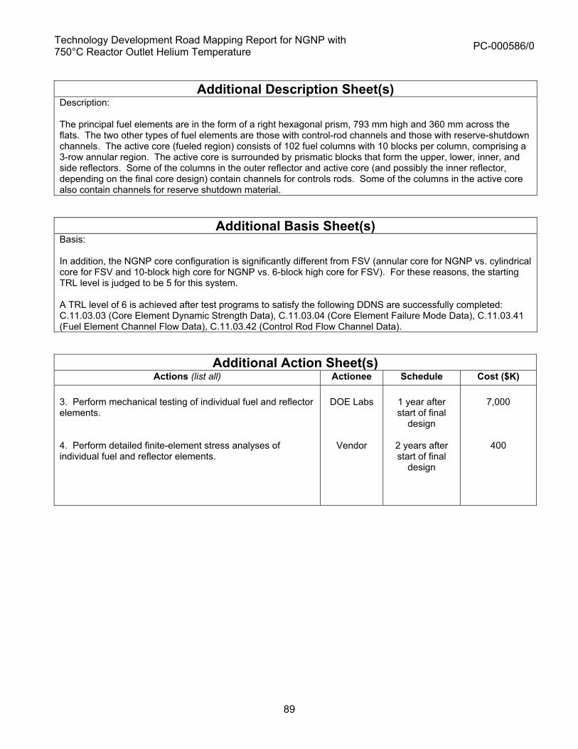
Technology Development Road Mapping Report for NGNP with 750°C Reactor Outlet Helium Temperature PC-000586/0
89
Additional Description Sheet(s)
Description: The principal fuel elements are in the form of a right hexagonal prism, 793 mm high and 360 mm across the flats. The two other types of fuel elements are those with control-rod channels and those with reserve-shutdown channels. The active core (fueled region) consists of 102 fuel columns with 10 blocks per column, comprising a 3-row annular region. The active core is surrounded by prismatic blocks that form the upper, lower, inner, and side reflectors. Some of the columns in the outer reflector and active core (and possibly the inner reflector, depending on the final core design) contain channels for controls rods. Some of the columns in the active core also contain channels for reserve shutdown material.
Additional Basis Sheet(s) Basis: In addition, the NGNP core configuration is significantly different from FSV (annular core for NGNP vs. cylindrical core for FSV and 10-block high core for NGNP vs. 6-block high core for FSV). For these reasons, the starting TRL level is judged to be 5 for this system. A TRL level of 6 is achieved after test programs to satisfy the following DDNS are successfully completed: C.11.03.03 (Core Element Dynamic Strength Data), C.11.03.04 (Core Element Failure Mode Data), C.11.03.41 (Fuel Element Channel Flow Data), C.11.03.42 (Control Rod Flow Channel Data).
Additional Action Sheet(s) Actions (list all) Actionee Schedule Cost ($K)
3. Perform mechanical testing of individual fuel and reflector elements. 4. Perform detailed finite-element stress analyses of individual fuel and reflector elements.
DOE Labs
Vendor
1 year after start of final
design
2 years after start of final
design
7,000
400

Technology Development Road Mapping Report for NGNP with 750°C Reactor Outlet Helium Temperature PC-000586/0
90
TRL Rating Sheet
Vendor: GA Document Number: RC2-SSC-4a.2 Revision: 0
Area System Subsystem/Structure Component Technology
Title: Reactor Core
Description: The primary functions of the Reactor Core are to generate high temperature heat using nuclear fission, transfer the heat to the helium coolant, and control radiation from the core. The Reactor Core consists of fuel elements, inner and outer reflector elements, upper reflector elements, and lower reflector elements (including flow distribution elements). All of these elements are hexagonal-shaped blocks manufactured from nuclear grade graphite. In terms of SSC categorization, the permanent side reflector is assumed to be part of Reactor Internals. (Cont. on additional description sheet)
Area: NHSS HTS HPS PCS BOP
PASSC: Parent: WBS:
Technology Readiness Level
Next Lower Rating Level
Current Rating Level
Next Higher Rating Level
Generic Definitions (abbreviated) Components verified at experimental scale
Subsystem verified at pilot scale
System verified at engineering scale
TRL 5 6 7 Basis for Rating (Check box if continued on additional sheets) TRL 6 is achieved for this system after all test data have been obtained and detailed modeling has been performed for the individual fuel and reflector elements to satisfy DDNs C.11.03.03, C.11.03.04, C.11.03.41, C.11.03.42, C.11.03.43, C.11.03.44. To advance to TRL 7, testing programs must be completed to satisfy the following DDNs: C.11.03.01 (Core Column Vibration Data), C.11.03.45 (Core Crossflow Test Data), C.11.03.46 (Core Fluctuation Test Data), C.11.03.43 (Bottom Reflector/Core Support Pressure Drop and Flow Mixing Data), C.11.03.44 (Metallic Plenum Element and Top Reflector Pressure Drop and Flow Distribution). Outline of plan to get from current level to next level. (Check box if continued on additional sheets)
Actions (list all) Actionee Schedule Cost ($K) 1. Perform multiple-block testing and to obtain core column vibration data. 2. Perform detailed modeling of core vibrations.
DOE Labs
Vendor
2 years after start of final
design
3 years after start of final
design
4,000
400
DDN(s) Supported: C.11.03.01, C.11.03.45, C.11.03.46
Technology Case File:
Subject Matter Expert Making Determination: Matt Richards Date: 12-8-08 Originating Organization: General Atomics

Technology Development Road Mapping Report for NGNP with 750°C Reactor Outlet Helium Temperature PC-000586/0
91
Additional Description Sheet(s)
Description: The principal fuel elements are in the form of a right hexagonal prism, 793 mm high and 360 mm across the flats. The two other types of fuel elements are those with control-rod channels and those with reserve-shutdown channels. The active core (fueled region) consists of 102 fuel columns with 10 blocks per column, comprising a 3-row annular region. The active core is surrounded by prismatic blocks that form the upper, lower, inner, and side reflectors. Some of the columns in the outer reflector and active core (and possibly the inner reflector, depending on the final core design) contain channels for controls rods. Some of the columns in the active core also contain channels for reserve shutdown material.
Additional Action Sheet(s) Actions (list all) Actionee Schedule Cost ($K)
3. Perform mock-up testing to obtain data for horizontal cross flow. 4. Perform detailed CFD analyses of cross flow. 5. Perform mock-up testing to obtain data for core flow fluctuations and hot streaks. 6. Perform CFD analyses of core flow fluctuations and hot streaks.
DOE Labs
Vendor
DOE Labs
Vendor
2 years after start of final
design
3 years after start of final
design
2 years after start of final
design
3 years after start of final
design
3,000
200
5,000
400

Technology Development Road Mapping Report for NGNP with 750°C Reactor Outlet Helium Temperature PC-000586/0
92
TRL Rating Sheet
Vendor: GA Document Number: RC2-SSC-4a.3 Revision: 0
Area System Subsystem/Structure Component Technology
Title: Reactor Core
Description: The Reactor Core consists of fuel elements, inner and outer reflector elements, upper reflector elements, and lower reflector elements (including flow distribution elements). All of these elements are hexagonal-shaped blocks manufactured from nuclear grade graphite. In terms of SSC categorization, the permanent side reflector is assumed to be part of Reactor Internals. The principal fuel elements are in the form of a right hexagonal prism, 793 mm high and 360 mm across the flats. The two other types of fuel elements are those with control-rod channels and those with reserve-shutdown channels. The active core (fueled region) consists of 102 fuel columns with 10 blocks per column, comprising a 3-row annular region. The active core is surrounded by prismatic blocks that form the upper, lower, inner, and side reflectors. Some of the columns in the outer reflector and active core (and possibly the inner reflector, depending on the final core design) contain channels for controls rods. Some of the columns in the active core also contain channels for reserve shutdown material.
Area: NHSS HTS HPS PCS BOP
PASSC: Parent: WBS:
Technology Readiness Level
Next Lower Rating Level
Current Rating Level
Next Higher Rating Level
Generic Definitions (abbreviated) Verified at pilot scale Verified at engineering
scale System tested and
qualified TRL 6 7 8 Basis for Rating (Check box if continued on additional sheets) TRL 7 is achieved for this system after all integral test data have been obtained and detailed modeling has been performed to satisfy DDNs C.11.03.01, C.11.03.45, and C.11.03.46.
Outline of plan to get from current level to next level. (Check box if continued on additional sheets)
Actions (list all) Actionee Schedule Cost ($K) 1. Perform instrumented tests as part of NGNP startup testing to confirm flow distributions, temperature distributions, and mechanical loadings are within design specifications.
GA/NGNP operator
TBD TBD
DDN(s) Supported: C11.03.01, C11.03.45, C.11.03.46
Technology Case File:
Subject Matter Expert Making Determination: Matt Richards Date: 12-8-08 Originating Organization: General Atomics

Technology Development Road Mapping Report for NGNP with 750°C Reactor Outlet Helium Temperature PC-000586/0
93
TRL Rating Sheet
Vendor: GA Document Number: RC2-SSC-4b.1 Revision: 0
Area System Subsystem/Structure Component Technology
Title: Graphite
Description: The graphite components of the reactor system are the core (fuel elements and replaceable reflector elements), the permanent side reflector, and the core support structure.
Area: NHSS HTS HPS PCS BOP
PASSC: Parent: WBS:
Technology Readiness Level
Next Lower Rating Level
Current Rating Level
Next Higher Rating Level
Generic Definitions (abbreviated) Component verified at experimental scale
Component verified at pilot scale
Component verified at engineering scale
TRL 5 6 7 Basis for Rating (Check box if continued on additional sheets) Nuclear-grade graphite is a mature technology and has been used previously in several HTGRS, including Ft. St. Vrain, which used block graphite elements manufactured from H-451 graphite. However, H-451 graphite is no longer commercially available and a graphite to replace H-451 is needed for a block-type NGNP core. The 30 MWt HTTR reactor in Oarai, Japan uses block graphite fuel and reflector elements manufactured from IG-110 graphite. (Cont.) Outline of plan to get from current level to next level. (Check box if continued on additional sheets)
Actions (list all) Actionee Schedule Cost ($K) 1. Perform test programs to obtain the requisite design data to advance to TRL 7 2. Obtain necessary ASME/ASTM code approvals. 3. Perform detailed modeling of in-core and accident-condition performance of graphite elements to establish design margins.
DOE Labs
Vendor / DOE Labs
Vendor
3 years before completion of final design.
2 years before completion of final design
1 year before completion of final design
84,000
2,000
1,500
DDN(s) Supported: C.11.03.11 through C.11.03.21 and C.11.03.23.
Technology Case File:
Subject Matter Expert Making Determination: Matt Richards Date: 10/30/08 Originating Organization: General Atomics

Technology Development Road Mapping Report for NGNP with 750°C Reactor Outlet Helium Temperature PC-000586/0
94
Additional Basis Sheet(s)
Basis: For NGNP, new nuclear-grade graphites are being developed and qualified, including grades PCEA, NBG-17 and NBG-18 that can be used for a block-type core. Because of the extensive experience base with the manufacture and irradiation of nuclear-grade graphite, a TRL level of 6 is judged to be appropriate for this component. A TRL level of 7 is achieved after the requisite design data have been obtained for the new graphite. These data are specified in the following Design Data Needs (DDNs): C.11.03.11 (Graphite Multiaxial Strength Data), C.11.03.12 (Graphite Fatigue Data), C.11.03.13 (Graphite Mechanical Properties Data), C.11.03.14 (Graphite Irradiation Induced Dimensional Change Data), C.11.03.15 (Graphite Irradiation Induced Creep Data), C.11.03.16 (Graphite Thermal Properties Data), C.11.03.17 (Graphite Fracture Mechanics Data), C.11.03.18 (Graphite Corrosion Data), C.11.03.19 (Graphite Corrosion Data for Methods Validation), C.11.03.20 (Graphite Destructive and Nondestructive Examination Data), C.11.03.21 (Graphite Coke Source Qualification), and C.11.03.23 (Graphite Oxidation Data for Postulated Accidents). These DDNs will be satisfied by completion of the graphite technology development plan described in INL document PLN-2497, Rev. 0. Note: Another possible strategy is to startup the NGNP without having obtained the complete data base as defined by the above DDNs and use data obtained during the startup phase (either from NGNP operation or ongoing testing at DOE laboratories) to satisfy some elements of these DDNs.

Technology Development Road Mapping Report for NGNP with 750°C Reactor Outlet Helium Temperature PC-000586/0
95
TRL Rating Sheet
Vendor: GA Document Number: RC2-SSC-4b.2 Revision: 0
Area System Subsystem/Structure Component Technology
Title: Graphite
Description: The graphite components of the reactor system are the core (fuel elements and replaceable reflector elements), the permanent side reflector, and the core support structure.
Area: NHSS HTS HPS PCS BOP
PASSC: Parent: WBS:
Technology Readiness Level
Next Lower Rating Level
Current Rating Level
Next Higher Rating Level
Generic Definitions (abbreviated) Component verified at pilot scale
Component verified at engineering scale
System tested and qualified
TRL 6 7 8 Basis for Rating (Check box if continued on additional sheets) TRL 7 is achieved for this system after design data have been obtained for a replacement to H-451 graphite. The required design data are described in the following Design Data Needs (DDNs): C.11.03.11 through C.11.03.21 and C.11.02.23. These DDNs will be satisfied by completion of the graphite technology development plan described in INL document PLN-2497, Rev. 0.
Outline of plan to get from current level to next level. (Check box if continued on additional sheets)
Actions (list all) Actionee Schedule Cost ($K) 1. Perform instrumented tests as part of NGNP startup testing to confirm physical, mechanical, thermal, and chemical properties. Perform inspections of selected fuel and reflector elements at the end of startup testing.
Vendor/ Operator
NGNP Startup Phase
15,000
DDN(s) Supported: None Technology Case File:
Subject Matter Expert Making Determination: Matt Richards Date: 10/30/08 Originating Organization: General Atomics

Tech
nolo
gy D
evel
opm
ent R
oad
Map
ping
Rep
ort f
or N
GN
P w
ith 7
50°C
Rea
ctor
Out
let H
eliu
m T
empe
ratu
re
PC
-000
586/
0
96
RC
2-S
SC
04a-
Rea
ctor
Cor
e Te
chno
logy
Roa
dmap
Rev
isio
n 0
4/21
/200
9 11
:01
AM
Test
s ne
cess
ary
to a
chie
ve T
RL
7
Per
form
mul
tiple
-blo
ck te
stin
g to
ob
tain
cor
e co
lum
n vi
brat
ion
data
.P
erfo
rm d
etai
led
mod
elin
g of
co
re v
ibra
tions
.P
erfo
rm m
ock-
up te
stin
g to
ob
tain
dat
a fo
r hor
izon
tal c
ross
flo
w.
Per
form
det
aile
d C
FD a
naly
ses
of c
ross
flow
.P
erfo
rm m
ock-
up te
stin
g to
ob
tain
dat
a fo
r cor
e flo
w
fluct
uatio
ns a
nd h
ot s
treak
s.P
erfo
rm C
FD a
naly
ses
of c
ore
flow
fluc
tuat
ions
and
hot
st
reak
s.
TRL7
Val
idat
ion
Rqm
t’s
Ver
ify n
o si
gnifi
cant
flow
indu
ced
vibr
atio
ns o
f cor
e co
lum
ns in
NG
NP
an
nula
r pris
mat
ic c
ore
unde
r any
reac
tor
oper
atin
g co
nditi
ons
(DD
N C
.11.
03.0
1)C
hara
cter
ize
flow
exc
hang
e at
cor
e el
emen
ts in
terfa
ces
betw
een
the
cool
ant
chan
nels
and
sur
roun
ding
gap
s be
twee
n co
lum
ns (c
ross
flow
) to
mee
t req
uire
men
ts
for c
ontro
l rod
tem
pera
ture
s, fu
el e
lem
ent
stre
sses
, and
fuel
tem
pera
ture
s. (D
DN
C
.11.
03.4
5)V
alid
ate
10 b
lock
hig
h ac
tive
core
and
as
soci
ated
refle
ctor
s ar
e st
able
to
mec
hani
cal a
nd th
erm
al m
ovem
ents
w
hich
wou
ld c
ause
fluc
tuat
ions
in th
e ou
tlet c
oola
nt te
mpe
ratu
res
(DD
N
C.1
1.03
.46)
Val
idat
e th
e co
re a
rray
will
be s
tabl
e an
d no
t adv
erse
ly a
ffect
ed b
y ex
pect
ed
heat
ing,
flow
and
pre
ssur
e dr
op
cond
ition
s. (D
DN
C.1
1.03
.43)
Val
idat
e co
mpu
ter c
odes
and
met
hods
for
pred
ictin
g th
ese
para
met
ers
Rea
ctor
C
ore
TRL
5
Syst
ems
TRL6
Val
idat
ion
Rqm
t’s
Est
ablis
h m
ean
valu
es o
f the
ex
perim
enta
lly d
eter
min
ed
failu
re lo
ads
high
er th
an
corr
espo
ndin
g an
alyt
ical
pr
edic
tions
.Es
timat
e th
e fri
ctio
n fa
ctor
s an
d lo
ss c
oeffi
cien
ts w
ith a
n ac
cura
cy o
f [10
%] a
t [95
%]
conf
iden
ce.
Acq
uire
Dyn
amic
Stre
ngth
D
ata
Acq
uire
Cor
e E
lem
ent F
ailu
re
Mod
e D
ata
Acq
uire
Fue
l Ele
men
t C
hann
el F
low
Dat
aA
cqui
re C
ontro
l Rod
Flo
w
Cha
nnel
Dat
a
Rea
ctor
Cor
e te
sts
Rea
ctor
Cor
e Ta
sks
to T
RL6
Per
form
The
rmal
/Flo
w
test
ing
of in
divi
dual
fuel
and
re
flect
or e
lem
ents
Per
form
det
aile
d C
FD
mod
elin
g of
indi
vidu
al fu
el
and
refle
ctor
ele
men
tsP
erfo
rm m
echa
nica
l tes
ting
of in
divi
dual
fuel
and
refle
ctor
el
emen
tsP
erfo
rm d
etai
led
finite
-el
emen
t stre
ss a
naly
sis
of
indi
vidu
al fu
el a
nd re
flect
or
elem
ents
Rea
ctor
Cor
e Te
stin
g
Test
s ne
cess
ary
to a
chie
ve
TRL
8
Inst
rum
ente
d te
sts
are
perfo
rmed
as
part
of N
GN
P s
tartu
p te
stin
g to
con
firm
flo
w d
istri
butio
ns,
tem
pera
ture
di
strib
utio
ns, a
nd
mec
hani
cal l
oadi
ngs
are
with
in d
esig
n sp
ecifi
catio
ns.
Full-
scal
e Te
stin
g of
th
e co
re
TRL8
Val
idat
ion
Rqm
t’s
Con
firm
atio
n of
flow
di
strib
utio
nsC
onfir
mat
ion
of lo
ads
Con
firm
atio
n of
te
mpe
ratu
re
dist
ribut
ions
Jan-
09Ja
n-21
Jan-
10Ja
n-11
Jan-
12Ja
n-13
Jan-
14Ja
n-15
Jan-
16Ja
n-17
Jan-
18Ja
n-19
Jan-
20
Cor
e El
emen
t Dyn
amic
Str
engt
h Te
stin
g
Pres
sure
Dro
p, T
empe
ratu
re D
istr
ibut
ion,
& F
low
Dis
trib
utio
n Te
stin
g
TRL
5
TRL
6
TRL
7
TRL
8
Sche
dule
Cor
e C
olum
n Vi
brat
ion
Test
ing
Cor
e El
emen
t Fai
lure
Mod
es
Fuel
Ele
men
t Flo
w C
hann
el T
estin
g
Con
trol
Rod
Flo
w C
hann
el T
estin
g
Cor
e C
ross
Flo
w T
estin
g
Cor
e Fl
uctu
atio
n Te
stin
g
Rea
ctor
Cor
e Te
stin
g
Full-
scal
e Te
sts
of th
e co
re
Rea
ctor
Cor
e Te
sts
Pres
sure
Dro
p an
d Fl
ow D
istr
ibut
ion
Test
ing
Tech
nolo
gy R
eadi
ness
Lev
els
Bas
icPr
inci
ples
O
bser
ved
Proo
f of
Con
cept
Ben
ch S
cale
Te
stin
g
Com
pone
nt
Dem
onst
rate
d at
Ex
perim
enta
l Sc
ale
Syst
em
Dem
onst
rate
d at
Eng
inee
ring
Scal
e
Inte
grat
ed
Prot
otyp
e Te
sted
an
d Q
ualif
ied
Plan
t O
pera
tiona
lA
pplic
atio
n Fo
rmul
ated
Subs
yste
m
Dem
onst
rate
d at
Pilo
t Sca
le
Tech
nolo
gyC
ompo
nent
Sub
syst
emS
yste
mPl
ant
12
34
56
78
910
Com
mer
cial
sc
ale
–M
ultip
le
Uni
ts
TRL
Lege
nd

Tech
nolo
gy D
evel
opm
ent R
oad
Map
ping
Rep
ort f
or N
GN
P w
ith 7
50°C
Rea
ctor
Out
let H
eliu
m T
empe
ratu
re
PC
-000
586/
0
97
Gra
phite
(Spe
cim
en) T
ests
(D
urat
ion,
Con
ditio
n-Lo
catio
n) t
o TR
L7RC
2-S
SC
04b-
Rea
ctor
Gra
phite
Tec
hnol
ogy
Roa
dmap
4/21
/200
9 11
:00
AM
TRL7
Ver
ifica
tion
Req
uire
men
ts
Verif
icat
ion
test
ing
of th
e m
ultia
xial
st
reng
th d
ata:
Prin
cipa
l Stre
ss
Rat
io,
Failu
re E
nvel
ope
Anal
ysis
Envi
ronm
enta
l co
nditi
ons:
Roo
m T
empe
ratu
re,
Uni
rrad
iate
d,
Non
-oxi
dize
d m
ater
ial
Test
s ne
cess
ary
to a
chie
ve
TRL
8
Inst
rum
ente
d te
sts
are
perfo
rmed
as
part
of
NG
NP
star
tup
test
ing
to
conf
irm p
hysi
cal,
mec
hani
cal,
ther
mal
, and
ch
emic
al p
rope
rties
. In
spec
tions
of s
elec
ted
fuel
an
d re
flect
or e
lem
ents
at
the
end
of s
tartu
p te
stin
g ar
e al
so p
erfo
rmed
.
Full-
scal
e Te
stin
g of
th
e co
re
TRL8
Val
idat
ion
Rqm
t’s
Jan-
09Ja
n-21
Jan-
10Ja
n-11
Jan-
12Ja
n-13
Jan-
14Ja
n-15
Jan-
16Ja
n-17
Jan-
18Ja
n-19
Jan-
20
Rea
ctor
G
raph
ite
Com
pone
nts
TRL6
Fuel
ele
men
t gr
aphi
te b
lock
s
Rep
lace
able
in
ner a
nd o
uter
re
flect
or
elem
ents
Upp
er re
flect
or
elem
ents
Low
er re
flect
or
elem
ents
(in
clud
ing
flow
di
strib
utio
n el
emen
ts)
Gra
phite
Mul
tiaxi
al
Stre
ngth
Tes
ting
Fatig
ue te
stin
g of
irr
adia
ted
and
unirr
adia
ted
sam
ples
Env
ironm
enta
l co
nditi
ons:
tem
pera
ture
s 25
–16
00o C
fast
flue
nces
<4
x 10
25n/
m2
Stre
ss ra
tio -1
to +
1S
tress
am
plitu
de
65%
-90
% m
ean
ultim
ate
stre
ngth
Gra
phite
Fat
igue
Te
stin
g
Mat
eria
l pro
perti
es
varia
bilit
y te
stin
g fro
m
vario
us c
oke
feed
stoc
k
Gra
phite
Cok
e S
ourc
e Q
ualif
icat
ion
Mec
hani
cal p
rope
rties
te
stin
gto
det
erm
ine
varia
bilit
y an
d m
ean
valu
es.
Pro
perti
es:
Flex
ural
stre
ngth
Tens
ile s
treng
thC
ompr
ehen
sive
st
reng
thS
tatic
and
dyn
amic
el
astic
mod
ulus
Poi
sson
’s ra
tioS
train
to fa
ilure
Gra
phite
Mec
hani
cal
Pro
perti
es T
estin
g
Cha
ract
eriz
atio
n te
stin
g fo
r the
fra
ctur
e m
echa
nics
of
gra
phite
Gra
phite
Fra
ctur
e M
echa
nics
Tes
ting
Cha
ract
eriz
atio
n te
stin
gfo
r tra
nspo
rt of
coo
lant
impu
ritie
s an
d gr
aphi
te
corro
sion
pro
duct
s in
gra
phite
and
the
intri
nsic
kin
etic
s fo
r th
e re
actio
n of
w
ater
with
gra
phite
Valid
ate
Cor
rosi
on
mod
el u
sing
se
para
te d
ata
Envi
ronm
enta
l co
nditi
ons:
Sam
ple
varia
bilit
yO
xida
tion
Tem
pera
ture
s Fa
st fl
uenc
es <
4 x
1025
n/m
2
Prim
ary
cool
ant
heliu
m, v
aryi
ng
H2O
, and
H2
conc
entra
tions
Burn
off >
2%To
rtuos
ity
Gra
phite
Cor
rosi
on
Test
ing
and
Mod
elin
g
Failu
re R
ate
Test
ing
Fiss
ion
Pro
duct
R
elea
se T
estin
gLo
caliz
ed
tem
pera
ture
and
ox
idat
ion
rate
te
stin
gE
ffect
s of
pot
entia
l C
O c
ombu
stio
n an
d hi
gh g
as
tem
pera
ture
s
Gra
phite
Oxi
datio
n Te
stin
g
Flaw
det
ectio
n m
etho
d te
stin
gE
ddy
curr
ent t
ests
,S
onic
vel
ocity
and
at
tenu
atio
n te
sts
Oth
er N
DE
te
chni
ques
Env
ironm
enta
l C
ondi
tions
:R
oom
tem
pera
ture
ai
r
Gra
phite
Des
truct
ive
and
Non
-Des
truct
ive
Test
ing
Failu
re R
ates
Fiss
ion-
Pro
duct
R
elea
se ra
tes
Che
mic
al h
eat-
gene
ratio
n ra
tes
Oxy
gen
diffu
sion
ra
tes
Effe
cts
on m
ater
ial
prop
ertie
s fro
m
burn
off
Mas
s-lo
ss ra
tes
CO
com
bust
ion
mod
elFl
amm
able
gas
bu
ildup
Oxi
datio
n ra
tes:
w
ithin
a fa
ctor
of 3
at
95%
con
fiden
ce
Gra
phite
Oxi
datio
n R
esul
ts
Edd
y cu
rren
t res
ults
fo
r fla
w d
etec
tion
Son
ic v
eloc
ity
corr
elat
ion
for e
last
ic
mod
ulus
Son
ic a
ttenu
atio
n co
rrel
atio
n fo
r ten
sile
st
reng
th
Gra
phite
Des
truct
ive
and
Non
-Des
truct
ive
Res
ults
Coo
lant
impu
ritie
s po
re
diffu
sion
rate
sP
erm
eatio
n du
e to
pr
essu
re g
radi
ents
Cha
ract
eriz
atio
n of
gr
aphi
te’s
por
osity
, to
rtuos
ity, a
nd
perm
eabi
lity
Rea
ctio
n ra
tes
as a
fu
nctio
n of
tem
pera
ture
, im
purit
y co
ncen
tratio
ns,
syst
em p
ress
ure,
and
tim
eE
ffect
s of
bur
noff
need
to
be
quan
tifie
d.E
ffect
s of
irra
diat
ion,
bi
llet v
aria
bilit
y, c
lass
va
riabi
lity,
lot v
aria
bilit
y,
and
spat
ial l
ocat
ion
in a
bi
llet m
ust b
e qu
antif
ied.
Val
idat
e co
rros
ion
mod
el
Gra
phite
Cor
rosi
on R
esul
ts
Crit
ical
stre
ss
inte
nsity
fact
ors
Stra
in e
nerg
y re
leas
e ra
tes
for
crac
k in
itiat
ion,
sta
ble
crac
k gr
owth
, and
cr
ack
arre
st
Gra
phite
Fra
ctur
e M
echa
nics
Res
ults
Dim
ensi
onal
cha
nge
test
ing
due
to
irrad
iatio
n,
tem
pera
ture
, va
riabi
lity
in m
ater
ial
prop
ertie
s, a
nd
oxid
atio
n En
viro
nmen
tal
cond
ition
s:Sa
mpl
e va
riabi
lity
Oxi
datio
nTe
mpe
ratu
res
550
–13
00o C
Fast
flue
nces
<4
x 10
25n/
m2
Gra
phite
Irra
diat
ion
Dim
ensi
onal
Cha
nge
Test
ing
Irrad
iatio
n-in
duce
d cr
eep
test
ing
to
char
acte
rize
the
cree
p be
havi
or o
f gr
aphi
te.
Envi
ronm
enta
l co
nditi
ons:
Isot
herm
al a
nd c
yclic
no
n-is
othe
rmal
co
nditi
ons
Cre
ep w
ith s
tress
re
vers
alte
mpe
ratu
res
550
–13
00o C
fast
flue
nces
<4
x 10
25n/
m2
Gra
phite
Irra
diat
ion-
Indu
ced
Cre
ep T
estin
g
Gen
erat
e th
erm
al
prop
ertie
s of
gra
phite
un
der v
ario
us
cond
ition
sEn
viro
nmen
tal
cond
ition
s:Sa
mpl
e va
riabi
lity
Oxi
datio
nTe
mpe
ratu
res
25 –
1600
o CFa
st fl
uenc
es <
4 x
1025
n/m
2
Ther
mal
Ann
ealin
g
Gra
phite
The
rmal
Pr
oper
ties
Test
ing
Fatig
ue D
ata
Hig
h fre
quen
cy te
st
resu
ltsM
inim
um fa
tigue
st
reng
th fo
r 99%
pr
obab
ility
of s
urvi
val
with
a c
onfid
ence
leve
l of
95%
ove
r a li
fetim
e of
102
to 1
05cy
cles
Gra
phite
Fat
igue
Res
ults
Mea
n va
lue
failu
re
surfa
ce a
nd v
aria
bilit
yM
inim
um s
treng
th
surfa
ce fo
r a s
urvi
val
prob
abilit
y of
99%
with
a
conf
iden
ce le
vel o
f 95
%
Gra
phite
Mul
tiaxi
al
Stre
ngth
Res
ults
Mea
sure
d di
strib
utio
n of
pro
perti
es fr
om
coke
sou
rce
Gra
phite
Cok
e So
urce
Q
ualif
icat
ion
Stre
ss-s
train
re
latio
nshi
psFl
exur
al s
treng
thTe
nsile
stre
ngth
Com
preh
ensi
ve
stre
ngth
Sta
tic a
nd d
ynam
ic
elas
tic m
odul
usP
oiss
on’s
ratio
Stra
in to
failu
re
Gra
phite
Mec
hani
cal
Pro
perti
es T
estin
g
Dim
ensi
onal
cha
nge
due
to ir
radi
atio
n w
ith
a 95
% c
onfid
ence
le
vel
Gra
phite
Irra
diat
ion
Dim
ensi
onal
Cha
nge
Test
ing
Irrad
iatio
n-in
duce
d cr
eep
data
for
isot
herm
al, c
yclic
no
n-is
othe
rmal
co
nditi
ons,
and
cre
ep
with
stre
ss re
mov
al
Gra
phite
Irra
diat
ion-
Indu
ced
Cre
ep T
estin
g
Ther
mal
con
duct
ivity
Coe
ffici
ent o
f the
rmal
ex
pans
ion
Emis
sivi
ty
Spec
ific
heat
Gra
phite
The
rmal
P
rope
rties
Tes
ting
Res
ults
of i
nstru
men
ted
test
s
Full-
scal
e Te
stin
g R
esul
ts o
f the
cor
e
Test
s on
Uni
rrad
iate
d Sa
mpl
es
Star
tup
Test
ing
in N
GN
P
TRL
6TR
L 7
TRL
8
Sche
dule
Test
s on
Irra
diat
ed S
ampl
es
Tech
nolo
gy R
eadi
ness
Lev
els
Bas
ic
Prin
cipl
es
Obs
erve
dPr
oof o
f C
once
ptB
ench
Sca
le
Test
ing
Com
pone
nt
Dem
onst
rate
d at
Ex
perim
enta
l Sc
ale
Syst
em
Dem
onst
rate
d at
Eng
inee
ring
Scal
e
Inte
grat
ed
Prot
otyp
e Te
sted
an
d Q
ualif
ied
Plan
t O
pera
tiona
lA
pplic
atio
n Fo
rmul
ated
Subs
yste
m
Dem
onst
rate
d at
Pilo
t Sca
le
Tech
nolo
gyC
ompo
nent
Subs
yste
mS
yste
mP
lant
12
34
56
78
910
Com
mer
cial
sc
ale
–M
ultip
le
Uni
ts
TRL
Lege
nd
Com
pone
nts

Technology Development Road Mapping Report for NGNP with 750°C Reactor Outlet Helium Temperature PC-000586/0
98
4.5 RC2-SSC-5 Reactor Pressure Vessel
TRL Rating Sheets, TRL 5 through 7
Technology Development Road Map

Technology Development Road Mapping Report for NGNP with 750°C Reactor Outlet Helium Temperature PC-000586/0
99
TRL Rating Sheet
Vendor: GA Document Number: RC2-SSC-5.1 Revision: 0
Area System Subsystem/Structure Component Technology
Title: Reactor Pressure Vessel (RPV)
Description: The RPV houses the reactor, the reactor internals, and the reactor support structure. The RPV consists of a main cylindrical section with hemispherical upper and lower heads. The upper head, which is bolted to the cylindrical section, has penetrations for the neutron control assemblies and in-vessel flux monitoring unit. The lower section, which is welded to the cylindrical section, has penetrations for the Shutdown Cooling System, the In-Service Inspection access, and source range neutron detectors. For a 600 MWt prismatic NGNP, the RPV would be larger in diameter (about 7.2 m I.D) than most LWR vessels, but the wall thickness would be comparable.
Area: NHSS HTS HPS PCS BOP
PASSC: Parent: WBS:
Technology Readiness Level
Next Lower Rating Level
Current Rating Level
Next Higher Rating Level
Generic Definitions (abbreviated) Component verified at bench scale
Component verified at engineering scale
Subsystem verified at pilot scale
TRL 4 5 6 Basis for Rating (Check box if continued on additional sheets) As discussed in GA report PC-000566, GA has concluded that SA-508/533 steel should be used as the material of construction for the NGNP RPV. SA-508/533 steel has an extensive experience base as the material used for current generation LWR RPVs, and it has been codified in Section III of the ASME code. The RPV for a 600-MWt prismatic NGNP would be larger in diameter than most LWR vessels, but the wall thickness would be comparable, and it has been determined that forgings of the (Cont.) Outline of plan to get from current level to next level. (Check box if continued on additional sheets)
Actions (list all) Actionee Schedule Cost ($K) 1. Develop RPV design requirements. This activity will include thermal-hydraulic analyses to calculate RPV temperatures and to assess the sensitivity of RPV temperatures to key parameters such as emissivity. Analyses will also be performed to define the design and expected helium impurity levels specific to (Cont.)
GA 9 months starting early in
CD
750
DDN(s) Supported: None Technology Case File:
Subject Matter Expert Making Determination: John Saurwein Date: 4-2-09 Originating Organization: General Atomics

Technology Development Road Mapping Report for NGNP with 750°C Reactor Outlet Helium Temperature PC-000586/0
100
Additional Basis Sheet(s)
Basis: required size are within the capabilities of a major forging supplier (Japan Steel Works). GA has also concluded that it will not be necessary to include an active vessel cooling system (VCS) in the NGNP design with a reactor outlet helium temperature of 750oC. The vessel operating temperature is only a concern if the temperatures are pushing against the 371°C ASME code limit for SA508/533 steel and the design lifetime of the RPV is very long (e.g., 60 years). With a reactor outlet helium temperature of 750°C, the reactor inlet helium temperature will be limited to 350°C, which will result in maximum vessel temperatures of about 320°C. Vessel temperatures at this level should be sufficiently low to eliminate any concerns with regard to vessel creep damage. Although there is a sufficient mechanical properties database for SA508/533, there is limited data available on the thermal aging effects on the mechanical properties, so additional information is needed on long-term aging effects. In particular, no data is available on the effects of impure helium on the long-term corrosion and mechanical properties of this material. Consequently, additional data on thermal aging and environmental effects are considered to be needed to support licensing. Also, as discussed in INL document PLN-2803, INL and ORNL have identified creep deformation as a potential concern for the NGNP SA-508/533 RPV and have recommended an extensive program of stress-rupture testing to address this concern. This concern derives from the 60-year design lifetime for the RPV and the environmental conditions within the RPV will be under during normal reactor operation. In summary, GA has assigned a technology readiness level (TRL) of 5 to the RPV based on the extensive experience base for SA508/SA533 as the material of construction for current generation LWR RPVs and codification of this material in Section III of the ASME code. GA does not consider long-term creep effects to be a potential problem for the NGNP RPV based on the assumption that the RPV temperature is below 350°C during normal reactor operations. Further, although some testing will be needed for confirmation and licensing purposes, GA does not believe that there are likely to be any significant deleterious effects of impure helium on the mechanical properties of the SA-508/533 vessel based on the experience with 2.25Cr-1Mo steel in the HTTR.

Technology Development Road Mapping Report for NGNP with 750°C Reactor Outlet Helium Temperature PC-000586/0
101
Additional Action Sheet(s) Actions (list all) Actionee Schedule Cost ($K)
the NGNP design and operating conditions. 2. Define required SA-508/533 testing program. This activity will involve preparation of an NGNP RPV materials research and development plan that is specific to the NGNP RPV conceptual design developed in Action 1. This plan will be based on INL document PLN-2803; however, it is believed that many of the tests recommended in PLN-2803 will be determined to be unnecessary because the design will keep RPV temperatures well below 350°C during normal reactor operations. 3. Conduct SA-508/533 testing in accordance with the NGNP RPV materials research and development plan from action 2
GA, INL, and ORNL
INL, ORNL, and/or
commercial materials testing
laboratories
4 months starting about one year into
CD
2.5 years starting as soon as the
testing program has been defined
350
9000

Technology Development Road Mapping Report for NGNP with 750°C Reactor Outlet Helium Temperature PC-000586/0
102
TRL Rating Sheet
Vendor: GA Document Number: RC2-SSC-5.2 Revision: 0
Area System Subsystem/Structure Component Technology
Title: Reactor Pressure Vessel (RPV)
Description: The RPV houses the reactor, the reactor internals, and the reactor support structure. The RPV consists of a main cylindrical section with hemispherical upper and lower heads. The upper head, which is bolted to the cylindrical section, has penetrations for the neutron control assemblies and in-vessel flux monitoring unit. The lower section, which is welded to the cylindrical section, has penetrations for the Shutdown Cooling System, the In-Service Inspection access, and source range neutron detectors. For a 600 MWt prismatic NGNP, the RPV would be larger in diameter (about 7.2 m I.D) than most LWR vessels, but the wall thickness would be comparable.
Area: NHSS HTS HPS PCS BOP
PASSC: Parent: WBS:
Technology Readiness Level
Next Lower Rating Level
Current Rating Level
Next Higher Rating Level
Generic Definitions (abbreviated) Component verified at experimental scale
Component verified at pilot scale
Component verified at engineering scale
TRL 5 6 7 Basis for Rating (Check box if continued on additional sheets) TRL 6 is achieved when the following conditions are met: (1) The design requirements for the RPV system have been defined, and (2) the necessary testing program for SA-508/533 has been defined and performed, and the data needed to support final design of the RPV and to support NGNP licensing has been obtained.
Outline of plan to get from current level to next level. (Check box if continued on additional sheets)
Actions (list all) Actionee Schedule Cost ($K) 1. Develop the final design of the RPV, and prepare and issue the procurement specifications for the RPV
GA 6 months starting early in
FD
250
DDN(s) Supported: None Technology Case File:
Subject Matter Expert Making Determination: John Saurwein Date: 4-2-09 Originating Organization: General Atomics

Technology Development Road Mapping Report for NGNP with 750°C Reactor Outlet Helium Temperature PC-000586/0
103
Additional Action Sheet(s)
Actions (list all) Actionee Schedule Cost ($K) 2. Develop the detailed design of the RPV and confirm that the design satisfies all ASME code rules for the RPV. Perform analyses to verify with high confidence that the maximum RPV temperatures will be within ASME code limits for SA-508/533 with adequate margin to eliminate concerns about creep effects over a 60-year lifetime.
GA
1 year starting about 1.5 years into NGNP FD
500

Technology Development Road Mapping Report for NGNP with 750°C Reactor Outlet Helium Temperature PC-000586/0
104
TRL Rating Sheet
Vendor: GA Document Number: RC2-SSC-5.3 Revision: 0
Area System Subsystem/Structure Component Technology
Title: Reactor Pressure Vessel (RPV)
Description: The RPV houses the reactor, the reactor internals, and the reactor support structure. The RPV consists of a main cylindrical section with hemispherical upper and lower heads. The upper head, which is bolted to the cylindrical section, has penetrations for the neutron control assemblies and in-vessel flux monitoring unit. The lower section, which is welded to the cylindrical section, has penetrations for the Shutdown Cooling System, the In-Service Inspection access, and source range neutron detectors. For a 600 MWt prismatic NGNP, the RPV would be larger in diameter (about 7.2 m I.D) than most LWR vessels, but the wall thickness would be comparable.
Area: NHSS HTS HPS PCS BOP
PASSC: Parent: WBS:
Technology Readiness Level
Next Lower Rating Level
Current Rating Level
Next Higher Rating Level
Generic Definitions (abbreviated) Component verified at pilot scale
Component verified at engineering scale
Component tested and qualified
TRL 6 7 8 Basis for Rating (Check box if continued on additional sheets) TRL 7 is achieved when the RPV analyses have been completed and verify with high confidence that the maximum RPV temperatures will be within ASME code limits for SA-508/533 with adequate margin to eliminate concerns about creep effects over a 60-year lifetime.
Outline of plan to get from current level to next level. (Check box if continued on additional sheets)
Actions (list all) Actionee Schedule Cost ($K) Conduct testing of the RPV in the actual operating environment (i.e., in the NGNP during start-up testing) to verify vessel temperatures are within the limits defined in the NGNP technical specifications. The first part of this activity will be to prepare the Test Specification (or alternately to define the test in the NGNP start-up plan).
GA, NGNP operator
During NGNP start-up testing
Cost to be covered
under NGNP start-up testing
DDN(s) Supported: None Technology Case File:
Subject Matter Expert Making Determination: John Saurwein Date: 4-2-09 Originating Organization: General Atomics

Tech
nolo
gy D
evel
opm
ent R
oad
Map
ping
Rep
ort f
or N
GN
P w
ith
750°
C R
eact
or O
utle
t Hel
ium
Tem
pera
ture
P
C-0
0058
6/0
105
Jan-
09Ja
n-20
Jan-
10Ja
n-11
Jan-
12Ja
n-13
Jan-
14Ja
n-15
Jan-
16Ja
n-17
Jan-
18Ja
n-19
RC
2-S
SC
05-R
eact
or P
ress
ure
Ves
sel T
echn
olog
y R
oadm
ap
4/21
/200
9 11
:01
AM
Syst
ems
Rea
ctor
P
ress
ure
Ves
sel
(RP
V) S
yste
mTR
L 5
Task
s to
TR
L6
Ther
mal
Agi
ngE
nviro
nmen
tal
Neu
tron
Irrad
iatio
n E
mbr
ittle
men
tTe
stin
g C
ondi
tions
:20
–55
0o C in
air
exce
pt s
tress
-ru
ptur
e te
sts
that
w
ill b
e pe
rform
ed
in im
pure
hel
ium
Mat
eria
l Pro
perti
es
Test
ing
Task
s ne
cess
ary
to
achi
eve
TRL7
Val
idat
ion
for T
RL7
Task
s ne
cess
ary
to
achi
eve
TRL8
Ver
ify th
e sy
stem
mee
ts re
liabi
lity
requ
irem
ents
and
m
aint
ains
ves
sel
tem
pera
ture
s w
ithin
the
limits
de
fined
in th
e N
GN
P te
chni
cal
spec
ifica
tions
.
Act
ual O
pera
ting
Env
ironm
ent
Dev
elop
RP
V
desi
gn
requ
irem
ents
: th
erm
al-
hydr
aulic
an
alys
is o
f RP
V
tem
pera
ture
s an
d se
nsiti
vity
to
emis
sivi
ty,
heliu
m im
purit
y le
vels
.
Des
ign
Req
uire
men
ts
Dev
elop
dat
a to
ch
arac
teriz
e th
e ne
utro
n-in
duce
d ni
l-duc
tility
tra
nsiti
on
tem
pera
ture
shi
ft in
SA
-508
/533
at
the
irrad
iatio
n te
mpe
ratu
res
and
neut
ron
flux,
flu
ence
, and
sp
ectru
m
expe
cted
for t
he
NG
NP.
Def
ine
SA
-508
/53
3 Te
stin
g P
rogr
am
TRL6
Val
idat
ion
Rqm
t’s
Ther
mal
-hyd
raul
ic a
naly
sis
of
RP
V te
mpe
ratu
res
and
sens
itivi
ty to
em
issi
vity
, hel
ium
im
purit
y le
vels
.
Des
ign
Req
uire
men
ts
Stre
ss-R
uptu
re D
ata
Rel
axat
ion
stre
ngth
Tens
ile p
rope
rties
Cre
ep-fa
tigue
resu
lts
Mat
eria
l Pro
perti
es T
estin
g
Req
uire
men
ts fo
r tes
ting
prog
ram
SA
-508
/533
Tes
ting
Pro
gram
Val
idat
ion
for T
RL8
Jan-
20Ja
n-21
Ves
sel
tem
pera
ture
is
with
in a
ppro
pria
te
limits
Actu
al O
pera
ting
Env
ironm
ent
Dev
elop
a fi
nal
desi
gn o
f the
RP
VP
repa
re
proc
urem
ent
spec
ifica
tions
Fina
l Des
ign
of th
e R
PV
Det
aile
d D
esig
n of
th
e R
PV
syst
emR
efin
emen
t of t
he
RPV
mod
elP
erfo
rm a
naly
ses
on th
e m
axim
um
vess
el te
mpe
ratu
reC
ore
fluct
uatio
n an
alys
isB
otto
m re
flect
or /
core
sup
port
Pre
ssur
e D
rop
and
Flow
mix
ing
test
ing
Met
allic
ple
num
el
emen
t / to
p re
flect
or P
ress
ure
Dro
p an
d Fl
ow
dist
ribut
ion
test
ing
Det
aile
d D
esig
n of
th
e R
PV
sys
tem
Com
plet
ed D
esig
n of
th
e R
PV
sys
tem
Upd
ated
RP
V m
odel
:el
imin
ate
cree
p co
ncer
ns o
ver 6
0 ye
ar
life
time
Ver
ify th
e m
axim
um
vess
el te
mpe
ratu
re is
w
ithin
AS
ME
cod
e lim
itsC
ore
fluct
uatio
n re
sults
Bot
tom
refle
ctor
/ co
re
supp
ort P
ress
ure
Dro
p an
d Fl
ow m
ixin
g re
sults
Met
allic
ple
num
el
emen
t / to
p re
flect
or
Pre
ssur
e D
rop
and
Flow
dis
tribu
tion
resu
lts
Det
aile
d D
esig
n of
the
RP
V s
yste
m
Com
plet
ion
of a
fina
l de
sign
of t
he R
PV
Pro
cure
men
t sp
ecifi
catio
ns
Fina
l Des
ign
of th
e R
PV
Dev
elop
Des
ign
Req
uire
men
ts
Com
plet
e Fi
nal D
esig
n an
d Pr
ocur
emen
t Spe
cs
Test
ing
of R
eact
or V
esse
l in
NG
NP
Con
ditio
ns
TRL
5
TRL
6
TRL
7
TRL
8
Sche
dule
Dev
elop
Det
ail D
esig
n
Def
ine
Test
ing
Prog
ram
Con
duct
SA
-508
/533
Tes
ting
Tech
nolo
gy R
eadi
ness
Lev
els
Bas
ic
Prin
cipl
es
Obs
erve
dPr
oof o
f C
once
ptB
ench
Sca
le
Test
ing
Com
pone
nt
Dem
onst
rate
d at
Ex
perim
enta
l Sc
ale
Syst
em
Dem
onst
rate
d at
Eng
inee
ring
Scal
e
Inte
grat
ed
Prot
otyp
e Te
sted
an
d Q
ualif
ied
Plan
t O
pera
tiona
lA
pplic
atio
n Fo
rmul
ated
Subs
yste
m
Dem
onst
rate
d at
Pilo
t Sca
le
Tech
nolo
gyC
ompo
nent
Subs
yste
mS
yste
mPl
ant
12
34
56
78
910
Com
mer
cial
sc
ale
–M
ultip
le
Uni
ts
TRL
Lege
nd

Technology Development Road Mapping Report for NGNP with 750°C Reactor Outlet Helium Temperature PC-000586/0
106
4.6 RC2-SSC-6 Helium Circulator
TRL Rating Sheets, TRL 6 and 7
Technology Development Road Map

Technology Development Road Mapping Report for NGNP with 750°C Reactor Outlet Helium Temperature PC-000586/0
107
TRL Rating Sheet
Vendor: GA Document Number: RC2-SSC-6.1 Revision: 0
Area System Subsystem/Structure Component Technology
Title: Helium Circulators (PHTS, SCS, SHTS)
Description: Main Circulator: The NGNP circulator is a variable speed, electric motor-driven axial flow helium compressor that facilitates thermal energy transfer from the reactor core to the steam generator and, hence, to the external turbo-generator set.
Area: NHSS HTS HPS PCS BOP
PASSC: Parent: WBS:
Technology Readiness Level
Next Lower Rating Level
Current Rating Level
Next Higher Rating Level
Generic Definitions (abbreviated) Item verified at experimental scale
Item verified at pilot scale
Item verified at engineering scale
TRL 5 6 7 Basis for Rating (Check box if continued on additional sheets) The NGNP helium circulator development builds on earlier studies carried out by circulator vendors for GA. The design proposed by Howden for the MHTGR program in 1989 was a two-stage axial flow machine running at 4500 rpm, with a maximum power rating of 4 MWe. It featured an induction motor and an AMB system. (Cont.)
Outline of plan to get from current level to next level. (Check box if continued on additional sheets)
Actions (list all) Actionee Schedule Cost ($K) 1. Bearing Design Verification: a. Determine static and dynamic axial thrust load capacities, stiffness, and damping coefficients over the operating speed range. b. Determine sensitivity of the associated electronic control system to external disturbances c. Rotor dynamic response to externally induced unbalance loads occurring in the impeller plane of rotation d. Magnitude of drag losses
Vendor, INL CTF or PBMR HTF
2012-2013 2,900
DDN(s) Supported: C.14.01.01, M.21.01.01, M.21.01.03
Technology Case File:
Subject Matter Expert Making Determination: Puja Gupta Date: 12-8-08 Originating Organization: General Atomics

Technology Development Road Mapping Report for NGNP with 750°C Reactor Outlet Helium Temperature PC-000586/0
108
Additional Basis Sheet(s)
Basis: Further to this, in 1993, Howden also designed the helium circulator for the New Production-Modular High Temperature Gas-cooled Reactor (NP-MHTGR) program. The selected design had radial flow impeller, oil-bath lubricated bearings, submerged motor drive, rotational speed of about 3000 rpm and a maximum power level of approximately 6 MWe. The James Howden Company has designed and built 112 machines for the commercial Advanced Gas Reactor (AGR) plants. Howden has designed a 4 MWe helium circulator to the concept stage for GA. Data on helium circulators are primarily available from component testing performed for Fort St. Vrain and the proposed Delmarva plant. The database has applicability limited to the design of axial compressors and shutoff valves. Considerable operating experience with magnetic bearings in various industrial applications has been accumulated, and covers the size and load range of a circulator of 4 to 5 MWe. Societe de Mecanique Magnetique (S2M), the world's leading manufacturer of magnetic bearings, has some proprietary data under various non-representative conditions. There is also experience with magnetic bearings for use in centrifuge enrichment equipment as part of some classified government programs. Part of this work has recently been declassified. Data on characteristics and performance of AMBs operating in conditions representative of the NGNP MC environment have not been established. There is a lack of data on the reliability of backup "catcher" bearings for vertical rotors to repeatedly support the turning rotor for a limited time when the active magnetic field supporting the rotor is lost.

Technology Development Road Mapping Report for NGNP with 750°C Reactor Outlet Helium Temperature PC-000586/0
109
Additional Action Sheet(s) Actions (list all) Actionee Schedule Cost ($K)
e. Development testing of alternate bearings, operating procedures, lubricants, and/or materials, if the reference design is unsatisfactory f. Evaluation of aerodynamic load simulation, including decay, in the test rig g. Demonstrate capability of catcher bearings to support the full scale vertical circulator rotor with failed AMBs during the coast down at all steady state, transient pressurized and depressurized operating conditions in helium
2. Scale Model Circulator Aerodynamic Flow Testing: a. Determine pressure rise across the compressor as a function of speed and helium flow through the compressor b. Determine overall efficiency including impeller and diffuser efficiency
Vendor, INL CTF or PBMR HTF
2012-2013 1,100
3. Motor Cooling Design and Insulation Dielectric Strength Verification: a. Measure necessary buffer gas flow to prevent the leakage of radioactive helium into the motor cavity b. Perform flashover tests in air at atmospheric pressure and in helium at three pressures: atmospheric, operating pressure, and an intermediate pressure to obtain flashover data as a function of helium pressure for the various insulation and rectifier components c. Obtain corona start data for the stator insulation versus helium pressure. d. Confirm the satisfactory performance of insulation and diode by test.
Vendor, INL CTF or PBMR HTF
2014 550

Technology Development Road Mapping Report for NGNP with 750°C Reactor Outlet Helium Temperature PC-000586/0
110
TRL Rating Sheet
Vendor: GA Document Number: RC2-SSC-6.2 Revision: 0
Area System Subsystem/Structure Component Technology
Title: Helium Circulators (PHTS, SCS, SHTS)
Description: Main Circulator: The NGNP circulator is a variable speed, electric motor-driven axial flow helium compressor that facilitates thermal energy transfer from the reactor core to the steam generator and, hence, to the external turbo-generator set.
Area: NHSS HTS HPS PCS BOP
PASSC: Parent: WBS:
Technology Readiness Level
Next Lower Rating Level
Current Rating Level
Next Higher Rating Level
Generic Definitions (abbreviated) Item verified at pilot scale
Item verified at engineering scale Item tested and qualified
TRL 6 7 8 Basis for Rating (Check box if continued on additional sheets) TRL 7 is achieved upon successful completion of the testing outlined in the TRL rating sheet for TRL 6 (and Section 3 of Test Plan 911138). Successful completion of these tests would demonstrate reliability/availability goals for the components such as insulation, diodes, motor cooling heat exchanger, shaft mounted motor cooling fans, journal and thrust AMB, catcher bearings, as well as full size labyrinth shaft seal have demonstrated reliability/availability goals under relevant environment. Outline of plan to get from current level to next level. (Check box if continued on additional sheets)
Actions (list all) Actionee Schedule Cost ($K) 1. Prototype Circulator Design Verification a. Buffer Helium Transient Tests b. Shaft Brake Test c. Low Speed Test d. Hot Restart Test e. Rapid Depressurization Test f. Endurance Test g. Acoustic and Vibration Test h. Spin Test
INL CTF or NGNP
Prototype Location
2014-2016 25,000
DDN(s) Supported: C.14.01.03, M.21.01.02, M.57.01.02
Technology Case File:
Subject Matter Expert Making Determination: Puja Gupta Date: 12-8-08 Originating Organization: General Atomics

Technology Development Road Mapping Report for NGNP with 750°C Reactor Outlet Helium Temperature PC-000586/0
111
Additional Action Sheet(s) Actions (list all) Actionee Schedule Cost ($K)
2. Extended Duration Testing INL CTF or NGNP
Prototype Location
2017 (qt 1,2)
3. Modified Main Circulator Testing (if necessary) INL CTF or NGNP
Prototype Location
2017 (qt 3,4)
4. Addition Circulators Proof Testing in Support of First Plant Operation
INL CTF or NGNP
Prototype Location
2018-2020

Tech
nolo
gy D
evel
opm
ent R
oad
Map
ping
Rep
ort f
or N
GN
P w
ith
750°
C R
eact
or O
utle
t Hel
ium
Tem
pera
ture
P
C-0
0058
6/0
112
Jan-
09Ja
n-21
Jan-
10Ja
n-11
Jan-
12Ja
n-13
Jan-
14Ja
n-15
Jan-
16Ja
n-17
Jan-
18Ja
n-19
Jan-
20
RC
2-S
SC
06-H
eliu
m C
ircul
ator
Tec
hnol
ogy
Roa
dmap
Rev
isio
n 0
4/21
/200
9 11
:04
AM
Hel
ium
C
ircul
ator
TRL
6
Subs
yste
ms
TRL8
Val
idat
ion
Rqm
t’s
Min
imum
200
ho
urs
of ru
ntim
eFa
ilure
Pro
babi
lity
<7
x 10
-5/h
rS
haft
orbi
t res
ults
fro
m lo
w s
peed
te
stV
alid
atio
n of
an
alyt
ical
m
etho
ds a
t low
sp
eed
Tem
pera
ture
re
sults
for h
ot
rest
art t
ests
.In
let a
nd o
utle
t no
ise
inte
nsity
an
d fre
quen
cy
spec
trum
Circ
ulat
or t
ests
He
Circ
ulat
or T
asks
to T
RL7
Full
size
laby
rinth
sh
aft s
eal s
yste
m
test
unde
r re
pres
enta
tive
plan
t ope
ratin
g co
nditi
ons
to
conf
irm it
s pe
rform
ance
and
in
tegr
ity
Sea
l Tes
ting
Per
form
ance
test
of c
ircul
ator
mot
or
cool
ing
heat
ex
chan
ger a
nd
the
shaf
t-mou
nted
m
otor
coo
ling
fans
. C
ompa
re
the
flow
re
sist
ance
s th
roug
h th
e ro
tor/
stat
or c
oolin
g pa
ssag
es w
ith
estim
ated
val
ues
Hel
ium
inje
ctio
n co
olin
g sy
stem
te
stto
pro
vide
pr
oper
sim
ulat
ion
of p
ress
uriz
ed
oper
atio
n, o
r to
prov
ide
supp
lem
enta
ry
bear
ing
cool
ing
as
part
of th
e de
sign
of
an
actu
al
bear
ing
syst
em.
Coo
ling
Sys
tem
Te
stin
gP
erfo
rman
ce te
stof
insu
latio
n an
d di
odes
und
er
pres
suriz
ing
and
depr
essu
rizin
g en
viro
nmen
tsQ
ualif
icat
ion
test
of th
e in
sula
tion
life
unde
r op
erat
ing
envi
ronm
ent i
n th
e co
rona
rang
eFl
asho
ver t
ests
on
sam
ples
of
insu
latio
n an
d re
ctifi
er
com
pone
nts
in a
ir at
atm
osph
eric
pr
essu
re a
nd in
he
lium
at t
hree
pr
essu
res:
at
mos
pher
ic,
oper
atin
g, a
nd
inte
rmed
iate
pr
essu
reE
lect
rical
in
sula
tion
test
for
AM
B a
t the
re
quire
d vo
ltage
s in
repr
esen
tativ
e he
lium
en
viro
nmen
t
Ele
ctric
al T
estin
g
Per
form
ance
test
of d
evel
oped
jo
urna
l and
thru
st
AM
B s
yste
ms
agai
nst p
roje
ct
requ
irem
ents
in
clud
ing
cons
ider
atio
n of
w
eigh
t sup
port,
co
ntro
l and
spe
ed
capa
bilit
y,
redu
ndan
cy a
nd
faul
t con
ditio
nsS
ubsc
ale
test
sof
th
e ca
tche
r be
arin
gs u
nder
re
pres
enta
tive
cond
ition
s,
cons
ider
ing
the
spec
ified
life
re
quire
men
t of 2
0 op
erat
ions
Bea
ring
Test
ing
He
Circ
ulat
or T
asks
to T
RL8
Per
form
ance
map
ping
te
sts
of c
ircul
ator
co
mpr
esso
r and
diff
user
in
clud
ing
pres
sure
rise
ac
ross
com
pres
sor a
s fu
nctio
n of
spe
ed a
nd
heliu
m fl
ow th
roug
h co
mpr
esso
r as
wel
l as
over
all e
ffici
ency
in
clud
ing
impe
ller a
nd
diffu
ser e
ffici
ency
Com
pres
sor a
nd D
iffus
er
Test
ing
Per
form
ance
test
son
fu
ll-sc
ale
circ
ulat
or
asse
mbl
y Q
ualif
icat
ion
test
son
fu
ll-sc
ale
circ
ulat
or
asse
mbl
y
Ver
ifica
tion
test
son
the
circ
ulat
or o
pera
tion
at
low
(5%
) spe
ed le
vel.
Hot
rest
art t
estf
or
circ
ulat
or:
100%
load
at o
pera
ting
spee
d an
d te
mpe
ratu
re,
no h
eliu
m fl
ow, a
nd
spee
d re
duct
ion
thro
ugh
the
shaf
t bra
ke.
Rap
id d
epre
ssur
izat
ion
test
to e
valu
ate
circ
ulat
or c
apab
ility
to
oper
ate
durin
g ac
cide
ntal
de
pres
suriz
atio
n of
he
lium
sys
tem
s:40
00 rp
m re
duce
d to
10
00 rp
m in
10s
, and
ba
ckup
to 4
000
rpm
in 1
m
in.
End
uran
ce te
sts
by
sim
ulat
ing
circ
ulat
or
star
tup
and
shut
dow
n op
erat
ing
cond
ition
s fo
r a
prol
onge
d pe
riod
of
cum
ulat
ive
runn
ing
time:
200h
rs o
f tes
ting,
oper
atin
g sp
eed
of 4
000
rpm
,ac
cele
ratio
n of
500
rpm
/m
in.,
NG
NP
ope
ratin
g te
mpe
ratu
res
and
pres
sure
s fo
r Hel
ium
Aco
ustic
and
vib
ratio
n te
sts
to e
stab
lish
the
acou
stic
noi
se le
vels
of
the
com
pres
sor a
nd
vibr
atio
n le
vels
of
com
pone
nts
of v
ario
us
criti
cal l
ocat
ions
with
in
circ
ulat
or a
nd te
st lo
op.
Circ
ulat
or T
estin
g
Ver
ifica
tion
test
sof
ci
rcul
ator
buf
fer h
eliu
m
syst
em p
erfo
rman
ce
and
to e
nsur
e th
at
circ
ulat
or s
ervi
ce
mod
ule
oper
atio
n is
co
mpa
tible
with
ci
rcul
ator
cap
abilit
ies.
Buf
fer H
eliu
m S
yste
m
Test
ing
Per
form
ance
test
sof
sh
aft b
rake
and
de
term
ine
the
prop
er
posi
tion
of th
e sh
aft
brak
e an
d ac
tuat
ion
of
the
brak
e on
shu
tdow
n.
For t
his
test
, it w
ill b
e ne
cess
ary
to a
ttain
de
sign
tem
pera
ture
s bu
t not
nec
essa
ry to
at
tain
des
ign
spee
d.
Sha
ft B
rake
Tes
ting
Effi
cien
cies
of t
he
impe
ller a
nd
diffu
ser
Pre
ssur
e dr
op
Com
pres
sor a
nd
Diff
user
test
s
Test
ing
at a
m
axim
um o
f 100
0 rp
m re
achi
ng 2
00
hrs
Sha
ft B
rake
test
s
Tran
sien
t tes
tsLi
mita
tions
for
flow
s an
d pr
essu
res
Buf
fer H
eliu
m
Sys
tem
tes
ts
TRL7
Val
idat
ion
Rqm
t’s
Leak
age
rate
s
Sea
l tes
ts
Thru
st: S
haft
supp
ort 6
000-
7000
lb
sTh
rust
: Life
time
>20
uses
bef
ore
failu
re o
r re
plac
emen
t Th
rust
: 18
Impa
ct
test
s un
der
depr
essu
rized
co
nditi
ons
and
2 un
der p
ress
uriz
ed
cond
tions
Jour
nal:
Spe
ed
6500
rpm
Jour
nal:
Var
iatio
n 5%
-104
%Jo
urna
l: Te
mpe
ratu
re <
600
Jour
nal:
Life
time
> 40
yrs
Bear
ing
test
s
Coo
ling
gas
flow
ra
tes
Dis
tribu
tion
of fl
owTe
mpe
ratu
res
and
Pre
ssur
e lo
ss:
mot
or,
bear
ings
,ro
tor,
stat
or,
and
win
ding
s.
Coo
ling
Sys
tem
test
s
Cor
ona
effe
cts
unde
r sta
rtup
with
vo
ltage
s up
to
2300
V
Mea
sure
insu
latio
n br
eakd
own
over
tim
eM
easu
rem
ents
of
the
flash
over
ef
fect
s as
a
func
tion
of
atm
osph
eric
gas
an
d pr
essu
re.
Ele
ctric
al t
ests
Iden
tify
Mag
netic
and
C
atch
er B
earin
g D
evel
opm
ent
Req
uire
men
ts
Prot
otyp
e C
ircul
ator
Des
ign
Verif
icat
ion
TRL
6
TRL
7TR
L 8
Sche
dule
Test
Pla
n fo
r Bea
ring
Dev
elop
men
t
Circ
ulat
or C
avity
Coo
ling
Syst
em T
ests
Bea
ring
Des
ign
Verif
icat
ion
Test
ing
Test
Art
icle
and
Fac
ility
Des
ign
Fabr
icat
ion
and
Proc
urem
ent
Tech
nolo
gy R
eadi
ness
Lev
els
Bas
ic
Prin
cipl
es
Obs
erve
dPr
oof o
f C
once
ptB
ench
Sca
le
Test
ing
Com
pone
nt
Dem
onst
rate
d at
Ex
perim
enta
l Sc
ale
Syst
em
Dem
onst
rate
d at
Eng
inee
ring
Scal
e
Inte
grat
ed
Prot
otyp
e Te
sted
an
d Q
ualif
ied
Plan
t O
pera
tiona
lA
pplic
atio
n Fo
rmul
ated
Subs
yste
m
Dem
onst
rate
d at
Pilo
t Sca
le
Tech
nolo
gyC
ompo
nent
Sub
syst
emS
yste
mP
lant
12
34
56
78
910
Com
mer
cial
sc
ale
–M
ultip
le
Uni
ts
TRL
Lege
nd

Technology Development Road Mapping Report for NGNP with 750°C Reactor Outlet Helium Temperature PC-000586/0
113
4.7 RC2-SSC-8 Shutdown Cooling Heat Exchanger
TRL Rating Sheets, TRL 4 through 7
Technology Development Road Map

Technology Development Road Mapping Report for NGNP with 750°C Reactor Outlet Helium Temperature PC-000586/0
114
TRL Rating Sheet
Vendor: GA Document Number: RC2-SSC-8.1 Revision: 0
Area System Subsystem/Structure Component Technology
Title: Shutdown Cooling Heat Exchanger (SCHE)
Description: The Shutdown Cooling Heat Exchanger (SCHE) is a multi-tube helical coil heat exchanger. It is similar in design to the evaporator/economizer portion of the FSV steam generator. Its function is to cool the reactor whenever the primary cooling system is not available. It is a vertical cross-counter flow heat exchanger. The tubes are made of 2-1/4 Croloy (ASTM A213, T22). The heat is removed by 60oC-pressurized (4.8MPa) water. The SCHE does not have a safety function.
Area: NHSS HTS HPS PCS BOP
PASSC: Parent: WBS:
Technology Readiness Level
Next Lower Rating Level
Current Rating Level
Next Higher Rating Level
Generic Definitions (abbreviated) Proof of concept Verified at bench scale Verified at
experimental scale TRL 3 4 5 Basis for Rating (Check box if continued on additional sheets) The Shutdown Cooling Heat Exchanger (SCHE) will be a helical coil tube heat exchanger similar in design to successfully operating heat exchangers in other gas cooled reactor plants including FSV and THTR. The previous experience with helical coiled heat exchangers has shown that the heat transfer correlations for flow across tube bundles match the predicted values (ASME Paper 79-WA/NE-1) thus providing a starting point for heat exchanger sizing. The selected tube material is 2-1/4 Croloy (ASTM A213, T22). Outline of plan to get from current level to next level. (Check box if continued on additional sheets)
Actions (list all) Actionee Schedule Cost ($K) Computer models will be used to evaluate the following: 1) The heat exchanger thermal sizing which is based on pressurized cooldown from 100% power operation. 2) The heat exchanger gas side pressure drop evaluation, which is based on depressurized cooldown from 100% power operation. 3) The structural evaluation of the tubes, which is based on the maximum tube temperature in a hot streak location. (Cont.)
GA 2 years starting at beginning of
conceptual design
2000
DDN(s) Supported: None Technology Case File:
Subject Matter Expert Making Determination: Dave Carosella, Bob Schleicher Date: 12-9-08 Originating Organization: General Atomics

Technology Development Road Mapping Report for NGNP with 750°C Reactor Outlet Helium Temperature PC-000586/0
115
Additional Action Sheet(s)
Actions (list all) Actionee Schedule Cost ($K) Actions: The shroud material, the shroud insulation and the shroud insulation cover sheet must be selected based on evaluation of the effect of the environment on the shroud its insulation and the insulation cover sheet. Analysis can be used to determine the shroud, the insulation and the insulation cover sheet temperature levels. Temperature levels must be determined for the following operating conditions: steady state operation at full power, conduction cooldown and shutdown on the SCHE. The possible shroud and cover sheet material choices include Alloy 800H, Inconel 617, Haynes 230 or Hastelloy XR. The possible shroud insulation choices include: Kaowool, Alltemp Insulation and porous carbon Insulation.

Technology Development Road Mapping Report for NGNP with 750°C Reactor Outlet Helium Temperature PC-000586/0
116
TRL Rating Sheet
Vendor: GA Document Number: RC2-SSC-8.2 Revision: 0
Area System Subsystem/Structure Component Technology
Title: Shutdown Cooling Heat Exchanger (SCHE)
Description: The Shutdown Cooling Heat Exchanger (SCHE) is a multi-tube helical coil heat exchanger. It is similar in design to the evaporator/economizer portion of the FSV steam generator. Its function is to cool the reactor whenever the primary cooling system is not available. It is a vertical cross-counter flow heat exchanger. The tubes are made of 2-1/4 Croloy (ASTM A213, T22). The heat is removed by 60oC-pressurized (4.8MPa) water. The SCHE does not have a safety function.
Area: NHSS HTS HPS PCS BOP
PASSC: Parent: WBS:
Technology Readiness Level
Next Lower Rating Level
Current Rating Level
Next Higher Rating Level
Generic Definitions (abbreviated) Verified at bench scale
Verified at experimental scale Verified at pilot scale
TRL 4 5 6 Basis for Rating (Check box if continued on additional sheets) TRL 5 will be achieved upon completion of the computer modeling activity described in the TRL rating sheet for TRL 4. In the computer modeling task, the heat exchanger was sized; the heat exchanger pressure drop was evaluated; the structural analysis was performed; and the temperatures and stress levels of the shroud, the insulation, and the insulation cover plates were calculated and used to select the materials for these components. Outline of plan to get from current level to next level. (Check box if continued on additional sheets)
Actions (list all) Actionee Schedule Cost ($K) The following tests will be performed on a mockup of an actual heat exchanger bundle with shrouds. 1. Perform testing of the SCHE shroud seal to determine measured leakage rates for combinations of different surface finishes, flatness tolerances, (cont.)
GA/SCHE vendor
2 years starting at beginning of
preliminary design
2150
DDN(s) Supported: C.14.04.01, C.14.04.05, C.14.04.06, C.14.04.07
Technology Case File:
Subject Matter Expert Making Determination: Dave Carosella, Bob Schleicher Date: 12-9-08 Originating Organization: General Atomics

Technology Development Road Mapping Report for NGNP with 750°C Reactor Outlet Helium Temperature PC-000586/0
117
Additional Action Sheet(s) Actions (list all) Actionee Schedule Cost ($K)
loads, and differential pressures under typical operating conditions. The shroud seal design consists of a metal bellows spring that compresses a circumferential seal. The testing will also include mechanical testing of the bellow assembly 2. Perform tests to characterize inlet flow and temperatures distributions under various operating modes and to determine the need for inlet flow distribution devices. If such devices are determined to be needed, perform tests to evaluate and compare candidate designs. 3. Perform tests to investigate the effects of acoustic noise on the large surface area structures of the SCHE. These tests will include the effects of coolant flow through the tube bundle so that the combined effects of acoustic noise and flow induced vibration can be assessed. 4. Evaluate the frequency response and dynamic loads of the insulation cover plates and attachments during the flow distribution and acoustics testing. 5. Determine the pressure drop flow characteristics of the water-side inlet orifice. Note: SCHE DDNs C.14.04.02, C.14.04.03, and C.14.04.09 will be satisfied by the steam generator technology development program

Technology Development Road Mapping Report for NGNP with 750°C Reactor Outlet Helium Temperature PC-000586/0
118
TRL Rating Sheet
Vendor: GA Document Number: RC2-SSC-8.3 Revision: 0
Area System Subsystem/Structure Component Technology
Title: Shutdown Cooling Heat Exchanger (SCHE)
Description: The Shutdown Cooling Heat Exchanger (SCHE) is a multi-tube helical coil heat exchanger. It is similar in design to the evaporator/economizer portion of the FSV steam generator. Its function is to cool the reactor whenever the primary cooling system is not available. It is a vertical cross-counter flow heat exchanger. The tubes are made of 2-1/4 Croloy (ASTM A213, T22). The heat is removed by 60oC-pressurized (4.8MPa) water. The SCHE does not have a safety function.
Area: NHSS HTS HPS PCS BOP
PASSC: Parent: WBS:
Technology Readiness Level
Next Lower Rating Level
Current Rating Level
Next Higher Rating Level
Generic Definitions (abbreviated) Verified at experimental scale Verified at pilot scale Verified at engineering
scale TRL 5 6 7 Basis for Rating (Check box if continued on additional sheets) TRL 6 is achieved upon successful completion of the SCHE design support testing identified in the TRL rating sheet for TRL 5. Achievement of TRL 6 for the SCHE is also dependent on successful completion of the elements of the steam generator design support testing program that is required to satisfy SCHE DDNs C.14.04.02 (vibrational fretting wear and sliding wear of wear protection devices for bare tubes), C14.04.03 (instrument attachment tests), and C14.04.09 (helical coil tube fabrication development). Outline of plan to get from current level to next level. (Check box if continued on additional sheets)
Actions (list all) Actionee Schedule Cost ($K) 1. Complete final design 2. Build a full-size prototype SCHE 3. Perform flow testing on the full size SCHE to verify thermal/hydraulic and flow induced vibration performance. This test will verify the heat transfer and pressure drop and flow induced vibration characteristics of the tube bundle.
GA
SCHE vendor
GA/Test Facility
2 years
1 year
1 year ending 3 years into
final design
3,000
6,000
5,000
DDN(s) Supported: C.14.04.08 Technology Case File:
Subject Matter Expert Making Determination: Dave Carosella, Bob Schleicher Date: 12-09-08 Originating Organization: General Atomics

Technology Development Road Mapping Report for NGNP with 750°C Reactor Outlet Helium Temperature PC-000586/0
119
TRL Rating Sheet
Vendor: GA Document Number: RC2-SSC-8.4 Revision: 0
Area System Subsystem/Structure Component Technology
Title: Shutdown Cooling Heat Exchanger (SCHE)
Description: The Shutdown Cooling Heat Exchanger (SCHE) is a multi-tube helical coil heat exchanger. It is similar in design to the evaporator/economizer portion of the FSV steam generator. Its function is to cool the reactor whenever the primary cooling system is not available. It is a vertical cross-counter flow heat exchanger. The tubes are made of 2-1/4 Croloy (ASTM A213, T22). The heat is removed by 60oC-pressurized (4.8MPa) water. The SCHE does not have a safety function.
Area: NHSS HTS HPS PCS BOP
PASSC: Parent: WBS:
Technology Readiness Level
Next Lower Rating Level
Current Rating Level
Next Higher Rating Level
Generic Definitions (abbreviated) Verified at pilot scale
Verified at engineering scale
Item tested and qualified
TRL 6 7 8 Basis for Rating (Check box if continued on additional sheets) TRL 7 is achieved upon successful completion of final design, fabrication of a full-size prototype SCHE, and the heat transfer and flow resistance characteristics testing identified in the TRL rating sheet for TRL 6.
Outline of plan to get from current level to next level. (Check box if continued on additional sheets)
Actions (list all) Actionee Schedule Cost ($K) Test the SCHE at all possible operating conditions including standby mode and transients. These tests are to be performed at design conditions in a helium environment and will verify the final performance characteristics of the SCHE.
INL CTF 2 years with completion 2 years before
NGNP startup testing
5,000
DDN(s) Supported: None Technology Case File:
Subject Matter Expert Making Determination: Dave Carosella, Bob Schleicher Date: 12-9-08 Originating Organization: General Atomics

Tech
nolo
gy D
evel
opm
ent R
oad
Map
ping
Rep
ort f
or N
GN
P w
ith
750°
C R
eact
or O
utle
t Hel
ium
Tem
pera
ture
P
C-0
0058
6/0
120

Technology Development Road Mapping Report for NGNP with 750°C Reactor Outlet Helium Temperature PC-000586/0
121
4.8 RC2-SSC-9 Reactor Cavity Cooling System
TRL Rating Sheets, TRL 4 through 7
Technology Development Road Map

Technology Development Road Mapping Report for NGNP with 750°C Reactor Outlet Helium Temperature PC-000586/0
122
TRL Rating Sheet
Vendor: GA Document Number: RC2-SSC-9.1 Revision: 0
Area System Subsystem/Structure Component Technology
Title: Reactor Cavity Cooling System (RCCS)
Description: The RCCS protects the concrete structure surrounding the reactor vessel from overheating during all modes of operation and provides an alternative means from removing reactor core decay heat when neither the PCS not the SCS is available. The RCCS cooling panels transfer heat from the reactor core to a passive outside air system. The RCCS panels also form a part of the barrier that separates the ambient atmosphere from the reactor cavity atmosphere.
Area: NHSS HTS HPS PCS BOP
PASSC: Parent: WBS:
Technology Readiness Level
Next Lower Rating Level
Current Rating Level
Next Higher Rating Level
Generic Definitions (abbreviated) Proof of Concept Component verified at
bench scale Component verified at
experimental scale TRL 3 4 5 Basis for Rating (Check box if continued on additional sheets) Sufficient conservative material properties data are available to demonstrate feasibility and to perform the required safety analyses. Natural convection heat transfer, buoyancy-driven flow, friction, and pressure loss are sufficiently understood based on experimental studies of basic phenomena. Expanded data is required to refine the design to include all operational environments anticipated.
Outline of plan to get from current level to next level. (Check box if continued on additional sheets)
Actions (list all) Actionee Schedule Cost ($K) 1. Conduct testing to determine the mean and variation of emissivity from one panel to the next. 2. Determine emissivity variation over a large surface. 3. Determine the sensitvity of emissivity to various factors including manufacturing processes, operating service conditions and aging.
Advanced Fuel
Research, Inc.
Exp. data 1 yr before start of final design.
Overall duration of 15
months.
194
DDN(s) Supported: C.16.00.01 Technology Case File:
Subject Matter Expert Making Determination: John Bolin Date: 12-8-08 Originating Organization: General Atomics

Technology Development Road Mapping Report for NGNP with 750°C Reactor Outlet Helium Temperature PC-000586/0
123
TRL Rating Sheet
Vendor: GA Document Number: RC2-SSC-9.2 Revision: 0
Area System Subsystem/Structure Component Technology
Title: Reactor Cavity Cooling System (RCCS)
Description: The RCCS protects the concrete structure surrounding the reactor vessel from overheating during all modes of operation and provides an alternative means from removing reactor core decay heat when neither the PCS not the SCS is available. The RCCS I/O structure is an above-grade structure that provides atmospheric air flow to and from the RCCS cooling panels.
Area: NHSS HTS HPS PCS BOP
PASSC: 1.4.3 Parent: 1.4 WBS:
Technology Readiness Level
Next Lower Rating Level
Current Rating Level
Next Higher Rating Level
Generic Definitions (abbreviated) Component verified at bench scale
Component verified at experimental scale
Subsystem verified at pilot scale
TRL 4 5 6 Basis for Rating (Check box if continued on additional sheets) TRL 5 is achieved upon successful completion of the RCCS panel emissivity testing called for in the TRL rating sheet for TRL 4.
Outline of plan to get from current level to next level. (Check box if continued on additional sheets)
Actions (list all) Actionee Schedule Cost ($K) The technical feasibility of the I/O structure concept has been demonstrated by a variety of similar applications: however, the RCCS outlet design is unique to MHR. No experimental or wind effect data exists for the configuration expected to be used that for the NGNP. Consequently, it is necessary to perform scale-model testing to determine pressure profiles inside and in the vicinity of I/O structure for various locations of the I/O structure along the length of the nuclear Island and for various wind directions and velocities.
Oran W. Nicks Low
Speed Wind Tunnel,
Texas A&M
Exp. data 1 yr before start of final design.
Overall duration 21 months.
400
DDN(s) Supported: C16.00.02 Technology Case File:
Subject Matter Expert Making Determination: John Bolin Date: 12-8-08 Originating Organization: General Atomics

Technology Development Road Mapping Report for NGNP with 750°C Reactor Outlet Helium Temperature PC-000586/0
124
TRL Rating Sheet
Vendor: GA Document Number: RC2-SSC-9.3 Revision: 0
Area System Subsystem/Structure Component Technology
Title: Reactor Cavity Cooling System (RCCS)
Description: The RCCS protects the concrete structure surrounding the reactor vessel from overheating during all modes of operation and provides an alternative means from removing reactor core decay heat when neither the PCS not the SCS is available. The RCCS cooling panels transfer heat from the reactor core to a passive outside air system. The RCCS panels also form a part of the barrier that separates the ambient atmosphere from the reactor cavity atmosphere.
Area: NHSS HTS HPS PCS BOP
PASSC: Parent: WBS:
Technology Readiness Level
Next Lower Rating Level
Current Rating Level
Next Higher Rating Level
Generic Definitions (abbreviated) Component verified at experimental scale
Subsystem verified at pilot scale
System verified at engineering scale
TRL 5 6 7 Basis for Rating (Check box if continued on additional sheets) TRL 6 is achieved when the subsystem testing called for in the TRL rating sheet for TRL 5 has been successfully completed. The next step is to test the complete system at less-than-full scale.
Outline of plan to get from current level to next level. (Check box if continued on additional sheets)
Actions (list all) Actionee Schedule Cost ($K) Perform engineering-scale-model testing to determine overall performance of the RCCS under all expected operating conditions. Determine effect of: 1. Temperature, heat flux, Reynolds number on heat transfer, friction factor data for geometrically similar riser tubes.
NSTF in Bldg 310 at
Argonne National
Lab
Exp. data before end of first year of final design.
Overall duration 24
months.
3,450
DDN(s) Supported: N.16.00.07, C.16.00.03, C.16.00.04
Technology Case File:
Subject Matter Expert Making Determination: John Bolin Date: 12-8-08 Originating Organization: General Atomics

Technology Development Road Mapping Report for NGNP with 750°C Reactor Outlet Helium Temperature PC-000586/0
125
Additional Action Sheet(s) Actions (list all) Actionee Schedule Cost ($K)
Actions: 2. Riser internal surface conditions on heat transfer and friction factor data for geometrically similar riser tubes. 3. Entry region conditions on heat transfer and friction factor data for geometrically similar riser tubes. 4. Buoyancy driven mixing in the high aspect ratio cavity between the vessel and RCCS panels.

Technology Development Road Mapping Report for NGNP with 750°C Reactor Outlet Helium Temperature PC-000586/0
126
TRL Rating Sheet
Vendor: GA Document Number: RC2-SSC-9.4 Revision: 0
Area System Subsystem/Structure Component Technology
Title: Reactor Cavity Cooling System (RCCS)
Description: The RCCS protects the concrete structure surrounding the reactor vessel from overheating during all modes of operation and provides an alternative means from removing reactor core decay heat when neither the PCS not the SCS is available. The RCCS cooling panels transfer heat from the reactor core to a passive outside air system. The RCCS panels also form a part of the barrier that separates the ambient atmosphere from the reactor cavity atmosphere.
Area: NHSS HTS HPS PCS BOP
PASSC: Parent: WBS:
Technology Readiness Level
Next Lower Rating Level
Current Rating Level
Next Higher Rating Level
Generic Definitions (abbreviated) Subsystem verified at pilot scale
System verified at engineering scale
System tested and qualified
TRL 6 7 8 Basis for Rating (Check box if continued on additional sheets) TRL 7 is achieved when RCCS system performance has been demonstrated at less-than-full scale in a relevant environment as called for in the TRL rating sheet for TRL 6 (see document RC2-SSC-9.3). The RCCS will achieve TRL of 8 by virtue of pre-commissioning testing at NGNP.
Outline of plan to get from current level to next level. (Check box if continued on additional sheets)
Actions (list all) Actionee Schedule Cost ($K) Perform testing of NGNP RCCS to verify design under all expected operating conditions.
As-built NGNP RCCS
Part of startup testing. Overall
duration 24 months.
Part of startup testing.
DDN(s) Supported: None Technology Case File:
Subject Matter Expert Making Determination: John Bolin Date: 12-8-08 Originating Organization: General Atomics

Tech
nolo
gy D
evel
opm
ent R
oad
Map
ping
Rep
ort f
or N
GN
P w
ith
750°
C R
eact
or O
utle
t Hel
ium
Tem
pera
ture
P
C-0
0058
6/0
127
Valid
atio
n to
Ach
ieve
TR
L5
TRL8
Val
idat
ion
Rqm
t’s
Jan
2009
Jan
2014
Jan-
10Ja
n-11
Jan-
12Ja
n-13
RC
2-S
SC
9-R
eact
or C
avity
Coo
ling
Sys
tem
Tec
hnol
ogy
Roa
dmap
RC
CS
TRL4Rev
isio
n 0
4/21
/200
9 11
:05
AM
Task
s to
TR
L5
Em
issi
vity
(mea
n &
var
iatio
n)
from
pan
el to
pan
elE
mis
sivi
ty v
aria
tion
over
larg
e su
rface
Em
issi
vity
Sen
sitiv
ity to
:M
fg P
roce
ss
In-s
ervi
ce O
pera
ting
Con
ditio
nsP
anel
Age
ing
Env
ironm
enta
l Con
ditio
ns:
Ser
vice
Life
:40
yea
rsR
elat
ive
Hum
idity
:0
to 1
00%
Ser
vice
Tem
pera
ture
s:S
hutd
own:
-45
to 1
10°F
Max
imum
acc
iden
t:43
0°F
appr
oxim
ate
Nor
mal
ope
ratio
n:22
0°F
max
imum
70°F
Am
bien
t Air
:18
0°F
aver
age
Coo
ling
Pane
ls T
estin
g
Task
to T
RL
7
NG
NP
air
RC
CS
sys
tem
un
der p
roto
typi
cal
cond
ition
s.D
ata
on th
e R
CC
S tu
be a
nd
chan
nel a
xial
tem
pera
ture
di
strib
utio
n un
der
prot
otyp
ical
flow
con
ditio
ns.
Dat
a on
the
RC
CS
tube
hea
t flu
x di
strib
utio
ns a
t pr
otot
ypic
al R
CC
S fl
ow
cond
ition
sD
ata
on th
e R
CC
S tu
be b
ulk
gas
velo
city
and
te
mpe
ratu
re d
istri
butio
ns.
Turb
ulen
ce d
ata
as a
fu
nctio
n of
axi
al p
ositi
on
with
in th
e R
CC
S tu
bes.
Prot
otyp
e Te
st R
esul
ts
Task
s to
TR
L8
Inst
rum
ent t
he fu
ll sc
ale,
as
built
NG
NP
RC
CS
sys
tem
to
yiel
d th
e de
sign
dat
aus
ed in
sc
ale
and
desi
gn p
hase
test
ing.
Mea
sure
the
axia
l and
radi
al
tem
pera
ture
and
hea
t flu
x di
strib
utio
ns o
n th
e tu
be w
alls
, an
d th
e he
ated
and
non
-hea
ted
duct
wal
ls to
det
erm
ine
the
loca
l he
at fl
uxes
and
the
asso
ciat
ed
heat
tran
sfer
coe
ffici
ents
, as
wel
l as
the
bulk
(or i
nteg
ral)
heat
rem
oval
rate
of t
he
syst
em.
Mea
sure
the
tube
inte
rior g
as
velo
city
and
tem
pera
ture
di
strib
utio
ns.
Mea
sure
turb
ulen
ce a
t sev
eral
ax
ial e
leva
tions
to re
duce
the
unce
rtain
ty in
the
appr
opria
te
form
of t
he tu
rbul
ence
mod
els
requ
ired
to a
ccur
atel
y co
mpu
te
the
flow
and
hea
t tra
nsfe
r be
havi
or in
the
NG
NP
RC
CS
.E
nviro
nmen
tal C
ondi
tions
:R
iser
sur
face
tem
pera
ture
: 15
0 -4
50°F
Ris
er s
urfa
ce h
eat f
lux:
M
axim
um a
ccid
ent:
10 k
W/ft
2
100%
pow
er o
pera
tion:
3 kW
/ft2
Low
pow
er o
pera
tion:
0.5k
W/ft
2
Rey
nold
s nu
mbe
r:M
axim
um a
ccid
ent:
~
105
100%
pow
er o
pera
tion:
104
to 1
05
Low
pow
er o
pera
tion:
103
to 1
04
NG
NP
Pro
toty
pe T
ests
Em
issi
vity
Val
ues
and
Var
ianc
eTe
mpe
ratu
re +
5°C
Em
issi
vity
+3%
Em
issi
vity
Sen
sitiv
ity
Fact
ors:
Mfg
Pro
cess
In
-ser
vice
Ope
ratin
g C
ondi
tions
Pan
el A
gein
g
Coo
ling
Pane
ls
Inle
t/Out
let S
truct
ures
Task
s to
TR
L6V
alid
atio
n R
equi
rem
ents
to
Achi
eve
TRL6 P
erfo
rm e
ngin
eerin
g-sc
ale-
mod
el te
stin
g to
det
erm
ine
over
all p
erfo
rman
ce o
f the
R
CC
S un
der a
ll ex
pect
ed o
pera
ting
cond
ition
s.M
ock
up A
ir R
CC
S g
eom
etry
und
er
prot
otyp
ical
con
ditio
ns.
Obt
ain
data
on
the
RC
CS
tube
and
ch
anne
l axi
al te
mpe
ratu
re d
istri
butio
n un
der p
roto
typi
cal f
low
con
ditio
ns.
Obt
ain
data
on
the
RC
CS
tube
hea
t flu
x di
strib
utio
ns a
t pro
toty
pica
l RC
CS
flow
co
nditi
ons
Obt
ain
data
on
the
RC
CS
tube
bul
k ga
s ve
loci
ty a
nd te
mpe
ratu
re d
istri
butio
ns.
Obt
ain
turb
ulen
ce d
ata
as a
func
tion
of
axia
l pos
ition
with
in th
e R
CC
S tu
bes.
Env
ironm
enta
l Con
ditio
ns:
Ris
er s
urfa
ce te
mpe
ratu
re:
150
-450
°FR
iser
sur
face
hea
t flu
x:
Max
imum
acc
iden
t:10
kW
/ft2
100%
pow
er o
pera
tion:
3 kW
/ft2
Low
pow
er o
pera
tion:
0.5k
W/ft
2
Rey
nold
s nu
mbe
r:M
axim
um a
ccid
ent:
~ 1
05
100%
pow
er o
pera
tion:
104
to 1
05
Low
pow
er o
pera
tion:
103
to 1
04
Hot
Ris
ers
& C
old
Dow
ncom
er
Valid
atio
n R
equi
rem
ents
to
Achi
eve
TRL7
Syst
ems
Per
form
sca
le-m
odel
test
ing
to
dete
rmin
e pr
essu
re p
rofil
esin
side
and
in
the
vici
nity
of I
/O s
truct
ure
for v
ario
us
loca
tions
of t
he I/
O s
truct
ure
alon
g th
e le
ngth
of t
he n
ucle
ar Is
land
and
for
vario
us w
ind
dire
ctio
ns a
nd v
eloc
ities
.
Inle
t/Out
let S
truct
ures
Sca
le
Mod
el T
ests
Pre
ssur
e P
rofil
es fo
r:
Var
ious
loca
tions
of t
he s
truct
ure
Win
d D
irect
ion
and
Vel
ocity
Inle
t/Out
let S
truct
ures
Sca
le
Mod
el R
esul
ts
Effe
ct o
f tem
pera
ture
, hea
t flu
x,
Rey
nold
s nu
mbe
r on
heat
tra
nsfe
r, fri
ctio
n fa
ctor
dat
a fo
r ge
omet
rical
ly s
imila
r ris
er tu
bes.
E
ffect
of r
iser
inte
rnal
sur
face
co
nditi
ons
on h
eat t
rans
fer a
nd
frict
ion
fact
or d
ata
for
geom
etric
ally
sim
ilar r
iser
tube
s.E
ffect
of e
ntry
regi
on c
ondi
tions
on
hea
t tra
nsfe
r and
fric
tion
fact
or
data
for g
eom
etric
ally
sim
ilar r
iser
tu
bes.
E
ffect
of b
uoya
ncy
driv
en m
ixin
g in
the
high
asp
ect r
atio
cav
ity
betw
een
the
vess
el a
nd R
CC
S
pane
ls.
Hot
Ris
ers
& C
old
Dow
ncom
er
Jan
2014
Jan
2021
Jan-
15Ja
n-16
Jan-
17Ja
n-18
Jan-
19Ja
n-20
Tech
nolo
gy R
eadi
ness
Lev
els
Bas
ic
Prin
cipl
es
Obs
erve
dPr
oof o
f C
once
ptB
ench
Sca
le
Test
ing
Com
pone
nt
Dem
onst
rate
d at
Ex
perim
enta
l Sc
ale
Syst
em
Dem
onst
rate
d at
Eng
inee
ring
Scal
e
Inte
grat
ed
Prot
otyp
e Te
sted
an
d Q
ualif
ied
Plan
t O
pera
tiona
lA
pplic
atio
n Fo
rmul
ated
Subs
yste
m
Dem
onst
rate
d at
Pilo
t Sca
le
Tech
nolo
gyC
ompo
nent
Sub
syst
emS
yste
mP
lant
12
34
56
78
910
Com
mer
cial
sc
ale
–M
ultip
le
Uni
ts
TRL
Lege
nd
Sche
dule
Emis
sivi
ty o
f RC
CS
Pane
l Sur
face
s Te
st
Win
d Tu
nnel
Tes
ting
of R
CC
S I/O
Str
uctu
re
Inte
grat
ed R
CC
S M
ocku
p Te
st
Test
ing
of S
CH
E fo
r NG
NP
Con
ditio
ns
TRL
5
TRL
6
TRL
7
TRL
8
TRL
4Fa
bric
ate
and
Inst
all R
CC
S in
NG
NP
Fina
l Des
ign
Prel
imin
ary
Des
ign
Con
cept
ual D
esig
n

Technology Development Road Mapping Report for NGNP with 750°C Reactor Outlet Helium Temperature PC-000586/0
128
4.9 RC2-SSC-10 Steam Generator
Steam Generator, 750°C Inlet Temperature, TRL Rating Sheets TRL 4 through 7
Technology Development Road Map

Technology Development Road Mapping Report for NGNP with 750°C Reactor Outlet Helium Temperature PC-000586/0
129
TRL Rating Sheet
Vendor: GA Document Number: RC2-SSC-10.1.1 Revision: 0
Area System Subsystem/Structure Component Technology
Title: Steam Generator – 750°C Gas Inlet Temperature
Description: The steam generator (SG) is a multi-tube, helical coil, cross-counter flow helium-to-water/steam heat exchanger similar in design to the FSV SG. In this SG, high-temperature helium @7MPa pressure heats feedwater @ 200oC & 19.5 MPa to 540oC steam @ 17.3MPa. The SG comprises two sections: the lower-temperature Economizer/Evaporator/ Superheater (EES) and the higher-temperature Finishing Superheater. The two sections are connected with a vertical tube section that is about 1 meter long. This vertical section, which is exterior to the main helium flow path, contains a bimetallic weld. A detailed description of the SG can be found in GA document 911120 “NGNP Steam Generator Alternative Study” and in the appropriate GA Test Plan.
Area: NHSS HTS HPS PCS BOP
PASSC: Parent: WBS:
Technology Readiness Level
Next Lower Rating Level
Current Rating Level
Next Higher Rating Level
Generic Definitions (abbreviated) Proof of Concept
Demonstrated at bench scale
Demonstrated at experimental scale
TRL 3 4 5 Basis for Rating (Check box if continued on additional sheets) GA has assigned a TRL of 4 to the 750°C SG primarily because (1) the FSV reactor experience has demonstrated the basic helical-coil SG thermal and hydraulic design and the SG material selections, and (2) the considerable level of SG design definition already available from the MHTGR Program. The validation of the helium-side heat transfer coefficients is documented in ASME paper 79-WA/NE-1. The FSV SG, although smaller then the NGNP SG was of the same basic configuration. The THTR heat exchanger was of similar design. Outline of plan to get from current level to next level. (Check box if continued on additional sheets)
Actions (list all) Actionee Schedule Cost ($K) Perform SG conceptual design and analysis. Use computer models to 1) Size the SG for design operating conditions @ 100% heat load, 2) Determine the steady state pressure drop, and 3) Perform structural analyses of the various SG components including the tubes and tube supports. Define the DDNs for the NGNP SG and prepare a design support program plan that outlines the testing required to satisfy the DDNs.
GA About 1.5 years with
completion by end of CD
3000
DDN(s) Supported: None Technology Case File:
Subject Matter Expert Making Determination: Dave Carosella Date: 12-10-08 Originating Organization: General Atomics

Technology Development Road Mapping Report for NGNP with 750°C Reactor Outlet Helium Temperature PC-000586/0
130
TRL Rating Sheet
Vendor: GA Document Number: RC2-SSC-10.1.2 Revision: 0
Area System Subsystem/Structure Component Technology
Title: Steam Generator – 750°C Gas Inlet Temperature
Description: The steam generator (SG) is a multi-tube, helical coil, cross-counter flow helium-to-water/steam heat exchanger similar in design to the FSV SG. In this SG, high-temperature helium @7MPa pressure heats feedwater @ 200oC & 19.5 MPa to 540oC steam @ 17.3MPa. The SG comprises two sections: the lower-temperature Economizer/Evaporator/ Superheater (EES) and the higher-temperature Finishing Superheater. The two sections are connected with a vertical tube section that is about 1 meter long. This vertical section, which is exterior to the main helium flow path, contains a bimetallic weld. A detailed description of the SG can be found in GA document 911120 “NGNP Steam Generator Alternative Study” and in the appropriate GA Test Plan.
Area: NHSS HTS HPS PCS BOP
PASSC: Parent: WBS:
Technology Readiness Level
Next Lower Rating Level
Current Rating Level
Next Higher Rating Level
Generic Definitions (abbreviated) Demonstrated at bench scale
Demonstration at experimental scale
Demonstrated at pilot scale
TRL 4 5 6 Basis for Rating (Check box if continued on additional sheets) TRL 5 is achieved when the design and analysis activities defined in the TRL rating sheet for TRL 4 have been successfully completed. Specifically, the conceptual design of the NGNP has been developed, including completion of analyses to size the SG, calculate the pressure drop, and verify the structural design. Additionally, the DDNs for the NGNP SG have been defined and a design support program plan that outlines the testing required to satisfy the DDNs has been prepared. Outline of plan to get from current level to next level. (Check box if continued on additional sheets)
Actions (list all) Actionee Schedule Cost ($K) 1) Demonstrate the ability to fabricate the helical coiled tubes.
GA/Vendor/ INL
1 year starting last year of
PD
1,250
DDN(s) Supported: M.13.02.01, M.13.02.02, M.13.02.03, M.13.02.04, M.13.02.07, M.13.02.08, M.13.02.10, M.13.02.11, M.13.02.12, M.13.02.14, M.13.02.15
Technology Case File:
Subject Matter Expert Making Determination: Dave Carosella Date: 12-14-08 Originating Organization: General Atomics

Technology Development Road Mapping Report for NGNP with 750°C Reactor Outlet Helium Temperature PC-000586/0
131
Additional Action Sheet(s) Actions (list all) Actionee Schedule Cost ($K)
Actions: 2) Perform mockup tests to establish lead-in lead-out and transition lead expansion and assembly room. 3) Select and design the SG tube support system and ware protection devices. Perform testing to assure no unacceptable tube ware due to vibration and/or fretting. 4) Perform testing to assure the ability to assemble the SG bundle using the support system. 5) Perform testing to verify the mechanical and thermal characteristics of the vessel insulation and its cover sheet. Tests must be performed at NGNP design operating conditions. 6) Perform air-flow testing to determine if vortex shedding and flow separation caused by the tube bundle will damage insulation cover sheets and/or flow shrouds. If damage occurs it will be necessary to design and test protection methods for the cover sheets and/or flow shrouds. 7) Perform testing to verify the mechanical and corrosion properties of alloy 800H under NGNP design conditions 8) Perform testing to verify the mechanical and corrosion properties of alloy 2¼Cr - 1Mo under NGNP design conditions 9) Perform testing to verify the mechanical properties of the bimetallic weld under NGNP design conditions. 10) Perform an airflow test of the steam generator inlet region to determine extent of flow maldistribution. b) Design and test flow control device to eliminate gas side flow maldistribution. 11) Perform flow testing to verify the flow/pressure drop characteristics of the orifice on the secondary side
GA/Vendor
GA/Vendor
GA/Vendor
GA/Vendor
GA/Vendor
GA/Test Lab/ INL
GA/Test Lab/
INL
GA/Test Lab/ INL
GA/Test Lab/
INL
GA/Test Lab
1 year Starting 2nd year of PD
1 year
Starting 2nd year of PD
1 Year
starting last year of PD
3 Years
starting at start of CD
1 year
Starting 2nd Year of PD
600
2,450
700
780
15,000
$1,090

Technology Development Road Mapping Report for NGNP with 750°C Reactor Outlet Helium Temperature PC-000586/0
132
TRL Rating Sheet
Vendor: GA Document Number: RC2-SSC-10.1.3 Revision: 0
Area System Subsystem/Structure Component Technology
Title: Steam Generator – 750°C Gas Inlet Temperature
Description: The steam generator (SG) is a multi-tube, helical coil, cross-counter flow helium-to-water/steam heat exchanger similar in design to the FSV SG. In this SG, high-temperature helium @7MPa pressure heats feedwater @ 200oC & 19.5 MPa to 540oC steam @ 17.3MPa. The SG comprises two sections: the lower-temperature Economizer/Evaporator/ Superheater (EES) and the higher-temperature Finishing Superheater. The two sections are connected with a vertical tube section that is about 1 meter long. This vertical section, which is exterior to the main helium flow path, contains a bimetallic weld. A detailed description of the SG can be found in GA document 911120 “NGNP Steam Generator Alternative Study” and in the appropriate GA Test Plan.
Area: NHSS HTS HPS PCS BOP
PASSC: Parent: WBS:
Technology Readiness Level
Next Lower Rating Level
Current Rating Level
Next Higher Rating Level
Generic Definitions (abbreviated) Demonstrated at experimental scale
Demonstrated at pilot scale
Demonstrated at engineering scale
TRL 5 6 7 Basis for Rating (Check box if continued on additional sheets) TRL 6 is achieved upon successful completion of the required design support testing defined in the TRL rating sheet for TRL 5.
Outline of plan to get from current level to next level. (Check box if continued on additional sheets)
Actions (list all) Actionee Schedule Cost ($K) 1. Complete final design and fabricate full-size prototype Steam Generator 2. Perform flow testing of full-size prototype SG to verify the heat transfer, pressure drop and vibration characteristics of the SG.
GA/SG vendor
GA/SG vendor
4 years starting at beginning of
FD
2 years with completion one
year before NGNP startup
TBD
6,000
DDN(s) Supported: None Technology Case File:
Subject Matter Expert Making Determination: Dave Carosella Date: 12-14-08 Originating Organization: General Atomics

Technology Development Road Mapping Report for NGNP with 750°C Reactor Outlet Helium Temperature PC-000586/0
133
TRL Rating Sheet
Vendor: GA Document Number: RC2-SSC-10.1.4 Revision: 0
Area System Subsystem/Structure Component Technology
Title: Steam Generator – 750°C Gas Inlet Temperature
Description: The steam generator (SG) is a multi-tube, helical coil, cross-counter flow helium-to-water/steam heat exchanger similar in design to the FSV SG. In this SG, high-temperature helium @7MPa pressure heats feedwater @ 200oC & 19.5 MPa to 540oC steam @ 17.3MPa. The SG comprises two sections: the lower-temperature Economizer/Evaporator/ Superheater (EES) and the higher-temperature Finishing Superheater. The two sections are connected with a vertical tube section that is about 1 meter long. This vertical section, which is exterior to the main helium flow path, contains a bimetallic weld. A detailed description of the SG can be found in GA document 911120 “NGNP Steam Generator Alternative Study” and in the appropriate GA Test Plan.
Area: NHSS HTS HPS PCS BOP
PASSC: Parent: WBS:
Technology Readiness Level
Next Lower Rating Level
Current Rating Level
Next Higher Rating Level
Generic Definitions (abbreviated) Demonstrated at pilot scale
Demonstrated at engineering scale
System tested and qualified
TRL 6 7 8 Basis for Rating (Check box if continued on additional sheets) TRL 7 is achieved upon successful completion of the air-flow testing of a full size SG to verify the heat transfer, pressure drop and vibration characteristics of the steam SG (as defined in the TRL rating sheet for TRL 6.
Outline of plan to get from current level to next level. (Check box if continued on additional sheets)
Actions (list all) Actionee Schedule Cost ($K) Test the steam generator thermal/hydraulic characteristics in the NGNP helium environment under design conditions including steady state and transient operating conditions.
GA/NGNP operator
1.5 years TBD
DDN(s) Supported: None Technology Case File:
Subject Matter Expert Making Determination: Dave Carosella Date: 12-14-08 Originating Organization: General Atomics

Tech
nolo
gy D
evel
opm
ent R
oad
Map
ping
Rep
ort f
or N
GN
P w
ith
750°
C R
eact
or O
utle
t Hel
ium
Tem
pera
ture
P
C-0
0058
6/0
134
TRL6
Val
idat
ion
Rqm
t’s
SG
Exp
erim
enta
l Sca
le T
asks
to T
RL
6
RC
2-S
SC
10-S
team
Gen
erat
or H
elic
al C
oil T
echn
olog
y R
oadm
ap
750o C
Ste
am
Gen
erat
or
Hel
ical
Coi
lTR
L 4
Rev
isio
n 0
4/21
/200
9 11
:06
AM
SG T
asks
to T
RL8
Full-
Sca
le te
stin
g of
th
e S
G fo
r the
rmal
/hy
drau
lic
char
acte
ristic
sin
a
heliu
m e
nviro
nmen
t un
der d
esig
n co
nditi
ons
incl
udin
g st
eady
sta
te a
nd
trans
ient
ope
ratin
g co
nditi
ons.
Ope
ratio
n Te
sts
TRL8
Val
idat
ion
Rqm
t’s
SG
is m
ount
ed in
te
st ri
g w
ith a
ll su
bsys
tem
s m
ade
oper
atio
nal,
such
as
hel
ium
sup
ply,
w
ater
sup
ply,
co
olan
t sup
ply,
po
wer
, etc
. S
tart
hot f
low
test
ing
with
sim
ulat
ed
trans
ient
eve
nts:
Tem
pera
ture
s,P
ress
ures
,Fl
ow ra
tes,
and
Freq
uenc
y lim
its
Jan-
09Ja
n-12
Jan-
10Ja
n-11
750o C
Inle
t M
ater
ials
: E
ES
Allo
y 80
0H
2-1/
4Cr-1
Mo
SG
Tas
ks to
TR
L5
Siz
e S
G fo
r des
ign
cond
ition
s at
10
0% h
eat l
oad
Det
erm
ine
the
stea
dy s
tate
pre
ssur
e dr
opP
erfo
rm s
truct
ural
ana
lysi
s of
SG
co
mpo
nent
s in
clud
ing
the
tube
s an
d tu
be s
uppo
rts
SG
Mod
elin
g an
d D
esig
n
TRL5
Val
idat
ion
Rqm
t’s
SG
Mod
elin
g an
d D
esig
n
Siz
e st
eam
gen
erat
orP
ress
ure
Dro
pS
truct
ural
ana
lysi
s re
sults
Ope
ratio
n Te
sts
SG
Tas
ks to
TR
L7
Con
stru
ct a
full
size
ste
am g
ener
ator
Per
form
airf
low
test
ing:
heat
tran
sfer
pro
perti
es,
pres
sure
dro
p, a
ndvi
brat
ion
char
acte
ristic
s
Full-
scal
e Te
sts
TRL7
Val
idat
ion
Rqm
t’s
Bui
lt a
full-
size
SG
Hea
t Tra
nsfe
r pro
perti
esP
ress
ure
Dro
pV
ibra
tion
Cha
ract
eris
tics
Full-
scal
e Te
sts
Jan-
21Ja
n-23
Jan-
22
Mat
eria
ls P
rope
rties
Test
ing
Mec
hani
cal p
rope
rties
of 2
-¼C
r-1M
o an
d Al
loy
800H
bas
e m
etal
s an
d th
eir
wel
dmen
ts in
a fo
rmat
com
para
ble
to
the
ASM
E C
ode
Cas
e N
-47
Mat
eria
ls P
rope
rties
Res
ults
Ther
mal
and
mec
hani
cal p
rope
rties
of
cand
idat
e m
ater
ials
:Yi
eld
and
tens
ile s
treng
thre
sults
Fatig
ue s
treng
th fr
om te
nsile
and
be
ndin
g lo
adin
g co
nditi
ons.
Mat
eria
l int
erm
edia
te fo
rms,
suc
h as
tu
be, r
od, p
late
, and
she
et, t
obe
m
anuf
actu
red
and
stre
ngth
test
ed.
Join
ing
tech
niqu
es re
sults
Impu
ritie
s le
vels
Cre
ep ru
ptur
e, lo
w-c
ycle
fatig
ue, a
nd
fract
ure
toug
hnes
s;
Irrad
iatio
n ef
fect
s on
stre
ss/s
train
an
d ul
timat
e st
reng
thC
orro
sion
effe
cts
over
full
rang
e of
He
and
wat
er/s
team
impu
rity
even
ts.
Bim
etal
lic w
eld
resu
lts
Syst
em
Mat
eria
ls
Test
ing
or c
ompu
ter s
imul
atio
ns to
de
term
ine
if vo
rtex
shed
ding
and
flow
se
para
tion
caus
ed b
y th
e tu
be b
undl
e w
ill d
amag
e in
sula
tion
cove
r she
ets
and/
or fl
ow s
hrou
ds.I
f dam
age
occu
rs it
will
be n
eces
sary
to d
esig
n an
d te
st p
rote
ctio
n m
etho
ds fo
r the
co
ver s
heet
s an
d/or
flow
shr
ouds
.
Flow
-Indu
ced
Vib
ratio
n Te
stin
g
Ver
ify a
bilit
y to
fabr
icat
e th
e he
lical
co
iled
tube
ste
am g
ener
ator
Test
ing
to a
ssur
e th
e ab
ility
to
asse
mbl
e th
e st
eam
gen
erat
or b
undl
e us
ing
the
supp
ort s
yste
m
Tube
Coi
l / T
hrea
ding
Fab
ricat
ion
Test
ing
Con
stru
ct h
elic
al c
oil s
team
gen
erat
orSG
ass
embl
y va
lidVe
rify
tool
des
ign,
tole
ranc
es
incl
udin
g el
liptic
ity, a
nd m
anuf
actu
ring
proc
edur
es
Tube
Coi
l / T
hrea
ding
Fab
ricat
ion
Res
ults
Sele
ct a
nd d
esig
n th
e st
eam
ge
nera
tor t
ube
supp
ort s
yste
m a
nd
wea
r pro
tect
ion
devi
ces.
The
supp
ort
syst
em a
nd th
e w
ear p
rote
ctio
n de
vice
s m
ust b
e de
sign
ed to
pre
vent
lo
cal t
ube
war
e at
the
supp
ort
loca
tions
. Tes
ting
mus
t be
perfo
rmed
to
ass
ure
no tu
be w
ear d
ue to
vi
brat
ion
and/
or fr
ettin
gPe
rform
moc
kup
or c
ompu
ter
sim
ulat
ions
to e
stab
lish
lead
-in, l
ead-
out,
and
trans
ition
lead
exp
ansi
on a
nd
asse
mbl
y ro
om
Addi
tiona
l Fab
ricat
ion
Test
ing
Siz
ing
of th
e or
ifice
Flow
test
ing
of th
e or
ifice
to v
erify
the
pres
sure
dro
p an
d flo
w
char
acte
ristic
s
Stab
ility
Inle
t Orif
ice
Test
ing
Pro
per s
izin
g of
the
orifi
ceW
ater
flow
rate
Wat
er te
mpe
ratu
reW
ater
pre
ssur
eP
ress
ure
drop
acr
oss
the
orifi
ce
Stab
ility
Inle
t Orif
ice
Res
ults
Per
form
airf
low
test
ing
or a
naly
sis
to
dete
rmin
e ex
tent
of f
low
m
aldi
strib
utio
nsin
the
inle
t reg
ion
of
the
SGD
esig
n an
d te
st fl
ow c
ontro
l dev
ice
to
elim
inat
e ga
s si
de fl
ow
mal
dist
ribut
ions
Air
Flow
Tes
ting
Test
ing
or c
ompu
ter s
imul
atio
ns m
ust
be p
erfo
rmed
to v
erify
the
mec
hani
cal
and
ther
mal
cha
ract
eris
tics
of th
e ve
ssel
insu
latio
n an
d its
cov
er s
heet
. Te
sts
mus
t be
perfo
rmed
at N
GN
P op
erat
ing
cond
ition
s.Te
stin
g C
ondi
tions
:H
e te
mpe
ratu
res:
260
o C –
750o C
Dur
atio
n: e
xpec
ted
life
of 6
0 ye
ars
Insu
latio
n Te
stin
g
Flow
ing
air f
or c
ross
duc
t Rey
nold
s N
umbe
r in
the
rang
e of
1.2
5x10
6(2
5%
pow
er) <
Re
< 3.
65x1
06(1
00%
pow
er)
in s
imila
r phy
sica
l con
ditio
ns
Air
Flow
Res
ults
‘Ref
lect
ive’
val
ue fo
r ins
ulat
ion
ther
mal
per
form
ance
sho
uld
be
mea
sure
d an
d in
corp
orat
ed in
the
desi
gner
s’ th
erm
al c
alcu
latio
nsIn
sula
tion
degr
adat
ion
and
wea
r in
term
s of
thic
knes
s or
den
sity
Insu
latio
n R
esul
ts
Des
ign
of S
G tu
be s
uppo
rt st
ruct
ure
and
wea
r pro
tect
ion
devi
ces
Lead
-in, L
ead-
out,
and
trans
ition
lead
ex
pans
ion
resu
lts
Add
ition
al F
abric
atio
n R
esul
ts
Det
erm
inat
ion
of d
amag
e vi
abilit
y to
in
sula
tion
cove
r she
ets
and/
or fl
ow
shro
uds
by v
orte
x sh
eddi
ng a
nd fl
ow
sepa
ratio
n
Flow
-Indu
ced
Vibr
atio
n R
esul
ts
Jan-
14Ja
n-21
Jan-
15Ja
n-16
Jan-
17Ja
n-18
Jan-
19Ja
n-20
Jan-
12Ja
n-14
Jan-
13
Stea
m G
ener
ator
Mod
elin
g an
d D
esig
n
Verif
icat
ion
of A
lloy
800H
and
2-1
/4C
r-1M
o, B
imet
allic
Wel
d
Flow
–In
duce
d Vi
brat
ion
(Aco
ustic
s)
Stab
ility
Orif
ice
Test
ing
Insu
latio
n Te
stin
g
Tube
Coi
l / T
hrea
ding
Ver
ifica
tion
Wea
r Pro
tect
ion
Test
s
Lead
Tub
e Te
st
Stea
m G
ener
ator
Fab
ricat
ion
SG T
estin
g in
Air
SG T
estin
g in
Hel
ium
TRL
5
TRL
6
TRL
4
TRL
7TR
L 8
Sche
dule
Tech
nolo
gy R
eadi
ness
Lev
els
Bas
ic
Prin
cipl
es
Obs
erve
dPr
oof o
f C
once
ptB
ench
Sca
le
Test
ing
Com
pone
nt
Dem
onst
rate
d at
Ex
perim
enta
l Sc
ale
Syst
em
Dem
onst
rate
d at
Eng
inee
ring
Scal
e
Inte
grat
ed
Prot
otyp
e Te
sted
an
d Q
ualif
ied
Plan
t O
pera
tiona
lA
pplic
atio
n Fo
rmul
ated
Subs
yste
m
Dem
onst
rate
d at
Pilo
t Sca
le
Tech
nolo
gyC
ompo
nent
Subs
yste
mS
yste
mP
lant
12
34
56
78
910
Com
mer
cial
sc
ale
–M
ultip
le
Uni
ts
TRL
Lege
nd

Technology Development Road Mapping Report for NGNP with 750°C Reactor Outlet Helium Temperature PC-000586/0
135
4.10 RC2-SSC-12 High Temperature Valves
TRL Rating Sheets, TRL 4 through 7
Technology Development Road Map

Technology Development Road Mapping Report for NGNP with 750°C Reactor Outlet Helium Temperature PC-000586/0
136
TRL Rating Sheet
Vendor: GA Document Number: RC2-SSC-12.1 Revision: 0
Area System Subsystem/Structure Component Technology
Title: High Temperature Isolation Valves and Pressure Relief Valve
Description: High temperature isolation valves, located in the steam circuit, enable isolation of the steam generator. Isolation valves are also present on the inlet of the branch to the power turbine, and on the inlet to the reboiler used to produce process steam. The Reactor Pressure Vessel is protected by a high temperature pressure actuated relief valve. Helium temperatures are assumed to be 750-800°C and 300-325°C for the hot and cold legs respectively. 241.4 kg/sec of steam is produced at 541�C and 17.25MPa, consistent with the CoGen plant described in the NGNP PCS alternatives report. The plant life is 60 years. It is also assumed that for isolation valves on the steam generator, there will be three (3) valves on the steam side of each hot and cold leg. These valves will be an integral part of the plant protective system actions for steam loop isolation events. (Reference GA Report 911120/0). Isolation and control valves may be 2 way or 3 way, globe, ball or gate type, Relief valves may be spring or pilot operated. In general, valves may be manual, automatic (remote) or actuated. Valves in some locations may require remote service.
Area: NHSS HTS HPS PCS BOP
PASSC: Parent: WBS:
Technology Readiness Level
Next Lower Rating Level
Current Rating Level
Next Higher Rating Level
Generic Definitions (abbreviated) Proof of Principal Component verified at
bench scale Component verified at
experimental scale TRL 3 4 5 Basis for Rating (Check box if continued on additional sheets) See attached Basis Sheet
Outline of plan to get from current level to next level. (Check box if continued on additional sheets)
Actions (list all) Actionee Schedule Cost ($K) See Action Sheets
DDN(s) Supported: N.42.02.01, N.42.02.02 Technology Case File:
Subject Matter Expert Making Determination: David T. Carroccia Date: 4-27-09 Originating Organization: Washington Division of URS

Technology Development Road Mapping Report for NGNP with 750°C Reactor Outlet Helium Temperature PC-000586/0
137
Additional Basis Sheet(s) Basis for rating: TRL-4 is assigned to the high temperature valves. Although the relief valve is expected to require more development then the steam isolation valves, it is assigned the same level as the steam valves. Steam isolation and control valves are commercially available in the size range needed with ratings that include the pressure and temperature noted above but material properties in the range necessary are not tabulated in the ASME Code Section III Subsection NH. Valves cannot be rated at TRL-5 because a complete specification for the high temperature high pressure high flow valves does not exist at the current time. The critical characteristics for which these valves must be designed are not defined for the service conditions at NGNP , particularly, the following must be established:
• ASME Section III Code Acceptance of materials • Allowable Valve Leakage • Valve response times required • Acceptable valve open pressure drop • Accident excursion temperatures • Accident excursion pressures • Valve Configuration • Actuator type • Application requirements and mounting location

Technology Development Road Mapping Report for NGNP with 750°C Reactor Outlet Helium Temperature PC-000586/0
138
Additional Action Sheet(s)
Actions (list all) Actionee Schedule Cost ($K) 1) Establish relevant standards and code applicability (ASME Boiler & pressure vessel Section III Class 1, nuclear, piping, NQA-1, ASME OM-1-2007, ASME OM-2008) a) Establish Safety Class 2) Determine thermal and mechanical properties of valve materials through coupon tests as needed (to fill gaps in the literature) including:
- Chemistry - Erosion - Room temperature material properties - Endurance limit analysis - Welds, Cladding - Material corrosion - Stress corrosion cracking, fracture toughness - Elevated temperature properties & fatigue data - Irradiation and post irradiation examination - Environmental exposure/embrittlement - Fasteners, and Seals - Helium permeability - Sliding surface friction - Variation in properties following exposure and aging - Actuator torque requirements - Performance characteristics - Lubrication - Remote Service Requirements - Determine applicability of EPRI PPM
3) Establish conditions of service under normal and design basis event conditions 4) Valve material stress testing 5) Material durability tests 6) Determine performance of gaskets, packing material and seals Cont’d
GA/URS-WD
GA
GA/URS-WD
GA
GA/URS-WD
GA/URS-WD & Valve Suppliers
GA/URS-WD
1 year
$300 to $350 (not including
GA Scope)
Material Testing
included in above cost estimate

Technology Development Road Mapping Report for NGNP with 750°C Reactor Outlet Helium Temperature PC-000586/0
139
7) Material Selection and Valve Configuration (Body, Bonnet, Seat, Seal, Stem and Packing) 8) 3D modeling and analytical simulation including FEA stress analysis, heat transfer analysis and CFD modeling 9) Endurance Limit and Creep Analysis 10) Identify Maintenance Requirements, ALARA analysis and RAMI characteristics 11) Erosion and corrosion accelerated wear testing, Environmental qualification of valve materials, He leak tightness & Weld Methods, Dissimilar Materials and Differential Thermal Expansion 12) Interfaces with adjoining structures, piping. Insulation, installation, maintenance access, contamination control
GA/URS-WD
GA/URS-WD
GA/URS-WD, SME
GA/URS-WD,
GA/URS-WD
GA/URS-WD
1.5year
$300 to $600k (not
including GA Scope)
Simulations, tests and analysis
included in above cost estimate

Technology Development Road Mapping Report for NGNP with 750°C Reactor Outlet Helium Temperature PC-000586/0
140
TRL Rating Sheet
Vendor: GA Document Number: RC2-SSC-12.2 Revision: 0
Area System Subsystem/Structure Component Technology
Title: High Temperature Isolation Valves and Pressure Relief Valve
Description: High temperature isolation valves, located in the steam circuit, enable isolation of the steam generator. Isolation valves are also present on the inlet of the branch to the power turbine, and on the inlet to the reboiler used to produce process steam. The Reactor Pressure Vessel is protected by a high temperature pressure actuated relief valve. Helium temperatures are assumed to be 750-800°C and 300-325°C for the hot and cold legs respectively. 241.4 kg/sec of steam is produced at 541�C and 17.25MPa, consistent with the CoGen plant described in the NGNP PCS alternatives report. The plant life is 60 years. It is also assumed that for isolation valves on the steam generator, there will be three (3) valves on the steam side of each hot and cold leg. These valves will be an integral part of the plant protective system actions for steam loop isolation events. (Reference GA Report 911120/0). Isolation and control valves may be 2 way or 3 way, globe, ball or gate type, Relief valves may be spring or pilot operated. In general, valves may be manual, automatic (remote) or actuated. Valves in some locations may require remote service.
Area: NHSS HTS HPS PCS BOP
PASSC: Parent: WBS:
Technology Readiness Level
Next Lower Rating Level
Current Rating Level
Next Higher Rating Level
Generic Definitions (abbreviated) Component verified at bench scale
Component verified at experimental scale
Component verified at pilot scale
TRL 4 5 6 Basis for Rating (Check box if continued on additional sheets) A TRL-5 is achieved upon successful completion of the action items identified in the TRL rating sheet for TRL-4. A complete specification for the high temperature, high pressure, high flow valves exists when TRL-5 is achieved. Outline of plan to get from current level to next level. (Check box if continued on additional sheets)
Actions (list all) Actionee Schedule Cost ($K) 1) Physical Test Preparation for Pilot Scale Test Articles
which are representative of valve designs 2) Tests using test apparatus 3) Determination of applicable NDE methods 4) Verify 3D (scale) models based on test results 5) Determine Leak Rate Detection Method Validation
GA/URS-WD
GA/URS-WD GA/URS-WD GA/URS-WD GA/URS-WD
1 year 400 - 450
DDN(s) Supported: N.42.02.01, N.42.02.02 Technology Case File:
Subject Matter Expert Making Determination: David T. Carroccia Date: 4-27-09 Originating Organization: Washington Division of URS

Technology Development Road Mapping Report for NGNP with 750°C Reactor Outlet Helium Temperature PC-000586/0
141
TRL Rating Sheet
Vendor: GA Document Number: RC2-SSC-12.3 Revision: 0
Area System Subsystem/Structure Component Technology
Title: High Temperature Isolation Valves and Pressure Relief Valve
Description: High temperature isolation valves, located in the steam circuit, enable isolation of the steam generator. Isolation valves are also present on the inlet of the branch to the power turbine, and on the inlet to the reboiler used to produce process steam. The Reactor Pressure Vessel is protected by a high temperature pressure actuated relief valve. Helium temperatures are assumed to be 750-800°C and 300-325°C for the hot and cold legs respectively. 241.4 kg/sec of steam is produced at 541�C and 17.25MPa, consistent with the CoGen plant described in the NGNP PCS alternatives report. The plant life is 60 years. It is also assumed that for isolation valves on the steam generator, there will be three (3) valves on the steam side of each hot and cold leg. These valves will be an integral part of the plant protective system actions for steam loop isolation events. (Reference GA Report 911120/0). Isolation and control valves may be 2 way or 3 way, globe, ball or gate type, Relief valves may be spring or pilot operated. In general, valves may be manual, automatic (remote) or actuated. Valves in some locations may require remote service.
Area: NHSS HTS HPS PCS BOP
PASSC: Parent: WBS:
Technology Readiness Level
Next Lower Rating Level
Current Rating Level
Next Higher Rating Level
Generic Definitions (abbreviated) Component verified at experimental scale
Component verified at pilot scale
Component verified at engineering scale
TRL 5 6 7 Basis for Rating (Check box if continued on additional sheets) A TRL of 6 is achieved upon successful completion of the action items identified in the TRL rating sheet for TRL 5. Outline of plan to get from current level to next level. (Check box if continued on additional sheets)
Actions (list all) Actionee Schedule Cost ($K) 1) Valve design verification including valve body, bonnet, plug, seal, packing, insulation, ball and seat, stem, bellows, jacket and actuator (as equipped) 2) Integrated experimental scale model testing including relief valve and isolation valve (Cont.)
GA/URS-WD 1 year 750 - 800
DDN(s) Supported: N.42.02.01, N.42.02.02 Technology Case File:
Subject Matter Expert Making Determination: David T. Carroccia Date: 4-27-09 Originating Organization: Washington Division of URS

Technology Development Road Mapping Report for NGNP with 750°C Reactor Outlet Helium Temperature PC-000586/0
142
Additional Action Sheet(s) Actions (list all) Actionee Schedule Cost ($K)
3) CFD/FEA validation and optimization 4) Leak detection validation 5) Validate installation, inspection and maintenance techniques 6) Assess test plan results and perform risk based analysis on need for next level of testing
GA/URS-WD GA/URS-WD GA/URS-WD GA/URS-WD
Included above

Technology Development Road Mapping Report for NGNP with 750°C Reactor Outlet Helium Temperature PC-000586/0
143
TRL Rating Sheet
Vendor: GA Document Number: RC2-SSC-12.4 Revision: 0
Area System Subsystem/Structure Component Technology
Title: High Temperature Isolation Valves and Pressure Relief Valve
Description: High temperature isolation valves, located in the steam circuit, enable isolation of the steam generator. Isolation valves are also present on the inlet of the branch to the power turbine, and on the inlet to the reboiler used to produce process steam. The Reactor Pressure Vessel is protected by a high temperature pressure actuated relief valve. Helium temperatures are assumed to be 750-800°C and 300-325°C for the hot and cold legs respectively. 241.4 kg/sec of steam is produced at 541�C and 17.25MPa, consistent with the CoGen plant described in the NGNP PCS alternatives report. The plant life is 60 years. It is also assumed that for isolation valves on the steam generator, there will be three (3) valves on the steam side of each hot and cold leg. These valves will be an integral part of the plant protective system actions for steam loop isolation events. (Reference GA Report 911120/0). Isolation and control valves may be 2 way or 3 way, globe, ball or gate type, Relief valves may be spring or pilot operated. In general, valves may be manual, automatic (remote) or actuated. Valves in some locations may require remote service.
Area: NHSS HTS HPS PCS BOP
PASSC: Parent: WBS:
Technology Readiness Level
Next Lower Rating Level
Current Rating Level
Next Higher Rating Level
Generic Definitions (abbreviated) Component verified at pilot scale
Component verified at engineering scale
Component tested and qualified
TRL 6 7 8 Basis for Rating (Check box if continued on additional sheets) A TRL of 7 is achieved upon successful completion of the action items identified in the TRL rating sheet for TRL 6. Risk based determination has been made at the previous level whether sufficient need exists to proceed to this level of testing. Outline of plan to get from current level to next level. (Check box if continued on additional sheets)
Actions (list all) Actionee Schedule Cost ($K) 1) Integrated CTF Testing (as part of a larger test effort)
2) Stress Analysis Validation by prescribed mechanical loading and strain gage measurements 3) Temperature and Flow Analysis Validation 4) In-Service Inspection Techniques Validation
GA/URS-WD /INL
GA/URS-WD
GA/URS-WD GA/URS-WD
2 years coordinated with other
activities at CTF)
750 – 950 Not including GA,INL/BEA
scope
DDN(s) Supported: N.42.02.01, N.42.02.02 Technology Case File: Subject Matter Expert Making Determination: David T. Carroccia Date: 4-27-09 Originating Organization: Washington Division of URS

Tech
nolo
gy D
evel
opm
ent R
oad
Map
ping
Rep
ort f
or N
GN
P w
ith
750°
C R
eact
or O
utle
t Hel
ium
Tem
pera
ture
P
C-0
0058
6/0
144

Technology Development Road Mapping Report for NGNP with 750°C Reactor Outlet Helium Temperature PC-000586/0
145
4.11 RC2-SSC-14 Fuel Handling and Storage System
TRL Rating Sheets, TRL 4 through 7
Technology Development Road Map

Technology Development Road Mapping Report for NGNP with 750°C Reactor Outlet Helium Temperature PC-000586/0
146
TRL Rating Sheet
Vendor: GA Document Number: RC2-SSC-14.1 Revision: 0
Area System Subsystem/Structure Component Technology
Title: Fuel Handling and Storage System (FHSS)
Description: The FHSS is used to refuel the reactor and for all transfers of fuel and reflector elements between the reactor and local storage facilities and between the local storage facilities and the packaging and shipping facility. The system is also used to manipulate special tools for in-service inspection of reactor components. The major fuel handling and storage components (subsystems) include the fuel handling machine (FHM), the fuel transfer cask (FTC), the fuel handling equipment positioner (FHEP), the fuel handling equipment support structure (FHESS), the element hoist and grapple assembly (EHGA) in the local fuel storage facility, and the fuel sealing and inspection facility (FSIF). (Cont.)
Area: NHSS HTS HPS PCS BOP
PASSC: Parent: WBS:
Technology Readiness Level
Next Lower Rating Level
Current Rating Level
Next Higher Rating Level
Generic Definitions (abbreviated) Proof of Concept Components verified at
bench scale Components verified at
experimental scale TRL 3 4 5 Basis for Rating (Check box if continued on additional sheets) A large experience base exists from designing, building, testing and operating fuel handling equipment for the Peach Bottom and Fort St. Vrain (FSV) reactors. Although the Peach Bottom fuel handling machine was manually operated, important technology was developed in the areas of: (1) electrical power and signal cables for operation in 450°F helium with high gamma background; (2) lubricants for use in the same harsh environment; (3) electronic sensors for use on the grapple head; (4) grapple head floating plate technology for light touch in horizontal and vertical directions; and (5) general purpose manipulator technology adapted for special use in the reactor. (Cont.) Outline of plan to get from current level to next level. (Check box if continued on additional sheets)
Actions (list all) Actionee Schedule Cost ($K) 1. Conduct conceptual design of the FHSS components. The design effort will include a review of the current designs (developed in the early 1990’s) and the current state of relevant technologies to ascertain the need for design changes to utilize current technology. Design improvements will be made based on the results of this review.
GA 18 months starting at the beginning of NGNP CD
1,900
DDN(s) Supported: C.21.01.04, C.21.01.07,C.21.01.08
Technology Case File:
Subject Matter Expert Making Determination: John Saurwein Date: 11-29-08 Originating Organization: General Atomics

Technology Development Road Mapping Report for NGNP with 750°C Reactor Outlet Helium Temperature PC-000586/0
147
Additional Description Sheet(s) Description: In-core fuel handling is performed by the FHM and the FTC working together. The functions of the various major FHSS components are summarized below: � The FHM is a shielded, gas tight structure containing all the necessary mechanisms required to transfer fuel
and reflector elements between the reactor core and the upper plenum � The FTC is a shielded structure which transfers fuel and reflector elements between the fuel handling
machine (inside the upper plenum) , and the FSIF and/or the Local Refueling and Storage Facilities (LRSF) � The FHESS receives and supports fuel handling equipment over the reactor vessel during refueling � The FHEP transfers and positions the FHM, FTC, FHESS, and auxiliary service cask between storage
locations, reactor vessel and fuel/target processing facilities floor valves � The EHGA robot is a remotely operated bridge robot in the LRSFs and FSIF which handle core elements,
well plugs, and fuel elements � The FSIF equipment loads spent fuel elements into shipping containers, seals the container lid, and
inspects the resulting container integrity. Operation of the FHSS is a key factor contributing to plant availability. The system must be highly reliable with sufficient redundancy to accommodate upset conditions and equipment failures. The equipment must minimize complexity and be readily maintainable, recognizing that it operates in a radioactive environment. These are all important requirements that require a comprehensive confirmation and endurance test program. The FHSS provides radiation protection to workers and public during refueling operations. The reactor containment is opened for refueling and the refueling equipment must be securely fastened and sealed to the pressure vessel. The equipment is designed to appropriate seismic requirements to maintain integrity with the reactor pressure vessel. Leakage of primary coolant from the reactor is prevented by maintaining the interior pressure slightly below atmospheric. In addition, the equipment is sealed to the reactor with elastomeric seals. In the event of upset conditions, such as an interior water leak, the equipment and seals are designed for the maximum pressure rise (approximately plus 25 psig). Machine controls and fail safe mechanisms are provided for the handling of fuel elements. Mislocating blocks, dropping or damaging blocks, or runaway machinery, etc., are concerns.

Technology Development Road Mapping Report for NGNP with 750°C Reactor Outlet Helium Temperature PC-000586/0
148
Additional Basis Sheet(s)
Basis: The FSV FHM was designed and built in the late 1960’s during the time that programmed machine tools were being developed for numerical control. This machine advanced from the Peach Bottom 1 technology in areas of: (1) computer control of multiple positioning systems in automatic mode or direct operator control in manual operation mode; (2) the use of electric motors, brakes, and position feedback instrumentation in a helium environment; (3) The use of a radiation-hardened television camera and lighting in helium; (4) programming techniques to safely operate the FHM within limits set by hard-wired interlocks and, (5) elementary inventory control, which was greatly enhanced in a 1989 control system upgrade. The current design for the FHSS has evolved from the FSV technology. Years of experience with the FSV FHM have demonstrated both reliable features of the design and some features which could be improved. The current FHM design is based on the FSV FHM, but includes some mechanisms that differ from the FSV FHM:
� Shorter grapple probe � Electrically controlled grapple mechanism rather than pneumatic � Electrically controlled grapple head mechanism rather than pneumatic � Increased handling mechanism linkage radial displacement � Viewing system and electronic control system revised to incorporate more current technology � Telescoping tube guide sleeve is transported and inserted by the FHM rather than an auxiliary service
cask � Vertical travel requirement is greater in order to operate in a deeper core
The FHSS also includes several new automated machines that must operate in concert. The simultaneous operation of these machines is necessary to refuel a reactor module within the allocated time. The FTC and the EHGA robot are new designs required to operate in a helium environment. These machines incorporate proven technology where applicable. For example, the FTC will use grapple head, telescopic guide tubes, and isolation valve designs similar to those used in the FHM. The FHEP is similar to a commercially available, computer operated gantry crane with position control of the x, y, z, and load rotation axes. The EHGA robot and its end effectors are similar to the gantry robots applied by GA in the U.S. Army chemical weapons demilitarization development program. GA has developed the robotics for the remote handling of munitions in a lethal agent environment. The particular relevant expertise gained and "lessons learned" in the design, use and control of multiple gantry robots, end-effectors, and decontamination compatible hardware is available and applicable to the gantry robots to be used in the LRSFs and the FSIF. The computer control and element accountability system will utilize background data derived from the FSV project, commercial HTGR designs, the GA Demil program and industrial applications of computer controlled equipment. The FSV and Demil projects provide tested data bases for the FHSS computer architecture which include automated serialized accounting of fuel elements and target assemblies. The baseline TRL assigned to the FHSS is 4 based on (1) the lowest TRL for the subsystems that comprise the FHSS and (2) the need to conduct tests to confirm the performance and environmental compatibility of instrumentation and control components and systems, and to firm up their design prior to overall system development and verification. A TRL of 4 is assigned to both the FHESS and the FSIF for the reasons given below. A TRL of 5 is assigned to the other FHSS subsystems based on the state of the technology as discussed above. The FHESS with its multiple interfaces (i.e., the reactor isolation valves and neutron control assembly housing seals) is a first-of-a-kind unit. Although design of the FHESS is a routine structural task based on loads, deflections, and stability of the structure, consideration must also be given to the radiation shielding needed to prevent unnecessary personnel radiation exposure. Adequate vendor documentation is expected to be available for the seals and valves to warrant a TRL of 4, but testing is needed to validate the performance of these components.

Technology Development Road Mapping Report for NGNP with 750°C Reactor Outlet Helium Temperature PC-000586/0
149
Little design information is currently available for the FSIF and the equipment will be first-of-a-kind; however, the fuel handling and packaging mechanisms and procedures used in this facility will be based on those employed in FSV and in other HTGRs. Further, as noted above, the relevant expertise gained and "lessons learned" in the design, use, and control of multiple gantry robots, end-effectors, and decontamination compatible hardware is available and applicable to the gantry robots to be used in the FSIF. Thus, an initial TRL of 4 is judged appropriate for this FHSS subsystem. It is also important to note that the conceptual designs of the current FHSS components were developed in the early 1990’s and were based on the technology available at that time. Further, the “technology development” activities defined for the FHSS in the technology development road map (TDRM) and supporting TRL rating sheets are primarily design verification tests. Thus, an important first step in NGNP FHSS technology development will be to review the current designs of the FHSS components and ascertain the extent to which previous design selections should be updated based on new technologies that have become available since the current designs were developed. It is not anticipated that any new technology will be need to be developed for the FHSS components; rather it is a matter of ensuring optimal utilization of currently available technology, particularly in the area of FHSS I&C.

Technology Development Road Mapping Report for NGNP with 750°C Reactor Outlet Helium Temperature PC-000586/0
150
Additional Action Sheet(s) Actions (list all) Actionee Schedule Cost ($K)
2. Perform a survey of the supply network for the types of equipment required for the NFSS and select vendors for the various components. 3. Complete preliminary design of the FHSS 4. Perform testing as necessary to verify the accuracy and reliability of the instrumentation and control components under a variety of operating conditions and after frequent use. Test the fuel element identification equipment under a range of operating conditions including element motion, velocity, size of identification markings, lighting conditions, etc. Test other instrumentation under various operating speeds and environmental conditions to verify performance characteristics. 5. Perform testing to demonstrate proper operation of the FHESS with its four built-in reactor isolation valves and inflatable seals. Test the inflatable seals that seat to the nuclear control assembly housings against offset (non-concentric) housing locations to simulate expected plant construction tolerances. Cycle valve operators and all seals to represent 10 refueling outages and demonstrate all interlocks. All testing will be conducted in ambient air. 6. Perform tests of FSIF components to verify the automated packaging, sealing, and inspection processes (including leak-tightness testing capabilities).
GA
GA, FHSS component
vendors
FHSS I&C vendor(s)
FHESS vendor
FSIF component
vendors
6 months starting upon completion of
action 1
18 months starting at
beginning of PD
9 months starting at
beginning of FD
1 year starting at beginning of
FD
1 year starting at beginning of
FD
350
3000
900
600
900

Technology Development Road Mapping Report for NGNP with 750°C Reactor Outlet Helium Temperature PC-000586/0
151
TRL Rating Sheet
Vendor: GA Document Number: RC2-SSC-14.2 Revision: 0
Area System Subsystem/Structure Component Technology
Title: Fuel Handling and Storage System (FHSS) Description: The FHSS is used to refuel the reactor and for all transfers of fuel and reflector elements between the reactor and local storage facilities and between the local storage facilities and the packaging and shipping facility. The system is also used to manipulate special tools for in-service inspection of reactor components. The major fuel handling and storage components (subsystems) include the fuel handling machine (FHM), the fuel transfer cask (FTC), the fuel handling equipment positioner (FHEP), the fuel handling equipment support structure (FHESS), the element hoist and grapple assembly (EHGA) in the local fuel storage facility, and the fuel sealing and inspection facility (FSIF). In-core fuel handling is performed by the FHM and the FTC working together. These machines are positioned by the FHEP and are mounted on the FHESS, which is mounted on the reactor vessel.
Area: NHSS HTS HPS PCS BOP
PASSC: Parent: WBS:
Technology Readiness Level
Next Lower Rating Level
Current Rating Level
Next Higher Rating Level
Generic Definitions (abbreviated) Components verified at bench scale
Components verified at experimental scale
Subsystems verified at pilot scale
TRL 4 5 6 Basis for Rating (Check box if continued on additional sheets) A TRL of 5 for the FHSS is achieved upon completion of the required component level testing for the FHESS and the FSIF. The tests on the FHESS seals and valves have qualified the materials used for these components and have verified the functionality and endurance of these components.
Outline of plan to get from current level to next level. (Check box if continued on additional sheets)
Actions (list all) Actionee Schedule Cost ($K) 1. Perform speed, accuracy, and extended cyclic endurance and structural testing of the FHEP to verify the design and to ensure the reliability and accuracy of the FHEP to retrieve, transport and place large, heavy machines and structures. The testing shall include measurement of the four-axis acceleration and velocity capabilities of the FHEP under static and dynamic load conditions to acquire the data needed to validate process speed and performance predictions. (Cont.)
GA and FHEP vendor
18 months staring at
beginning of FD
1900
DDN(s) Supported: C.21.01.01, C.21.01.02, C.21.01.03, C.21.01.06
Technology Case File:
Subject Matter Expert Making Determination: John Saurwein Date: 11-29-08 Originating Organization: General Atomics

Technology Development Road Mapping Report for NGNP with 750°C Reactor Outlet Helium Temperature PC-000586/0
152
Additional Basis Sheet(s)
Basis: Experimental-scale testing of the FSIF components has verified the automated packaging, sealing, and inspection processes to be used in this subsystem. Testing of the FHSS instrumentation and control (I&C) components in air and in helium has demonstrated the performance and environmental compatibility of these components and has demonstrated that the I&C, including software, meets design requirements and is compatible with the fuel handling mechanisms used in the FHSS.
Additional Action Sheet(s) Actions (list all) Actionee Schedule Cost ($K)
The safety interlocks of the FHEP control system will be validated in the course of these tests. 2. Perform EHGA robot testing to validate that material handling operations for all fuel element related tasks are done within the cycle time allocation. Predicted recovery tasks will be functionally tested. Environmental endurance testing in both air and helium will be performed. 3. Perform full-scale rig test to acquire data for FHM on functional and performance limits in anticipated operating modes and operating conditions: Phase 1: Automated checkout of grapple head Phase 2: Automated checkout of element transfer mechanisms over a full core sector Phase 3: Automated cycle test in 250°F helium 4. Use a full-scale test rig and test article to conduct tests in air (Phase 1) and helium (Phase 2) to establish the operability and reliability of the FTC and its components under expected environmental conditions. Key components include the vertical drive system for the hoist grapple, horizontal transfer table drive, and the complete grapple system. Test Phase 3 will be a separate cyclic test of the automated hold-downs and remote connections. 5. Complete final design of the FHSS based on the results of all component testing. Issue final procurement specifications for all equipment.
GA and EHGA vendor
GA and FHM vendor
GA and FTC vendor
GA
18 months starting at
beginning of FD
18 months starting at
beginning of FD
18 months starting at
beginning of FD
2 years starting 18 months into
FD
850
1250
1250
1500

Technology Development Road Mapping Report for NGNP with 750°C Reactor Outlet Helium Temperature PC-000586/0
153
TRL Rating Sheet
Vendor: GA Document Number: RC2-SSC-14.3 Revision: 0
Area System Subsystem/Structure Component Technology
Title: Fuel Handling and Storage System (FHSS)
Description: The FHSS is used to refuel the reactor and for all transfers of fuel and reflector elements between the reactor and local storage facilities and between the local storage facilities and the packaging and shipping facility. The system is also used to manipulate special tools for in-service inspection of reactor components. The major fuel handling and storage components (subsystems) include the fuel handling machine (FHM), the fuel transfer cask (FTC), the fuel handling equipment positioner (FHEP), the fuel handling equipment support structure (FHESS), the element hoist and grapple assembly (EHGA) in the local fuel storage facility, and the fuel sealing and inspection facility (FSIF). In-core fuel handling is performed by the FHM and the FTC working together. These machines are positioned by the FHEP and are mounted on the FHESS, which is mounted on the reactor vessel.
Area: NHSS HTS HPS PCS BOP
PASSC: Parent: WBS:
Technology Readiness Level
Next Lower Rating Level
Current Rating Level
Next Higher Rating Level
Generic Definitions (abbreviated) Components verified at experimental scale
Subsystems verified at pilot scale
System verified at engineering scale
TRL 5 6 7 Basis for Rating (Check box if continued on additional sheets) A TRL of 6 is achieved upon completion of all design verification testing of the FHSS subsystems including the FHM, FTC, FHEP, FHESS, EHGA, and the FSIP and either (1) the results of the tests confirm that the subsystems meet all functional and operational requirements or (2) design modifications have been made to the final design to correct any deficiencies detected during testing.
Outline of plan to get from current level to next level. (Check box if continued on additional sheets)
Actions (list all) Actionee Schedule Cost ($K) Perform an integrated test of the FHSS to verify that all components of the system function together and that system operations can be performed safely and reliably within the allocated time. The testing will involve full-scale fuel handling and control equipment with simulated fuel elements in an environment representative of the operational environment.
GA, component
vendors, and testing
organization
2.5 years with completion at least 6 months
before installation of equipment at
NGNP
6000
DDN(s) Supported: C.21.01.05 Technology Case File:
Subject Matter Expert Making Determination: John Saurwein Date: 11-29-08 Originating Organization: General Atomics

Technology Development Road Mapping Report for NGNP with 750°C Reactor Outlet Helium Temperature PC-000586/0
154
TRL Rating Sheet
Vendor: GA Document Number: RC2-SSC-14.4 Revision: 0
Area System Subsystem/Structure Component Technology
Title: Fuel Handling and Storage System (FHSS)
Description: The FHSS is used to refuel the reactor and for all transfers of fuel and reflector elements between the reactor and local storage facilities and between the local storage facilities and the packaging and shipping facility. The system is also used to manipulate special tools for in-service inspection of reactor components. The major fuel handling and storage components (subsystems) include the fuel handling machine (FHM), the fuel transfer cask (FTC), the fuel handling equipment positioner (FHEP), the fuel handling equipment support structure (FHESS), the element hoist and grapple assembly (EHGA) in the local fuel storage facility, and the fuel sealing and inspection facility (FSIF). In-core fuel handling is performed by the FHM and the FTC working together. These machines are positioned by the FHEP and are mounted on the FHESS, which is mounted on the reactor vessel.
Area: NHSS HTS HPS PCS BOP
PASSC: Parent: WBS:
Technology Readiness Level
Next Lower Rating Level
Current Rating Level
Next Higher Rating Level
Generic Definitions (abbreviated) Subsystems verified at pilot scale
System verified at engineering scale
System tested and qualified
TRL 6 7 8 Basis for Rating (Check box if continued on additional sheets) A TRL of 7 is achieved when the following conditions are satisfied: (1) The integrated system test with simulated fuel elements in an environment representative of the operating environment, and (2) The results of the integrated system test demonstrate that all of the subsystems function together and that the FHSS is capable of performing all required operations safely and reliably in the allocated time.
Outline of plan to get from current level to next level. (Check box if continued on additional sheets)
Actions (list all) Actionee Schedule Cost ($K) Conduct the appropriate number and duration of fuel handling operations in the actual operating environment (i.e., in the NGNP) to verify that the system meets reliability requirements.
GA, NGNP operator
During NGNP startup testing
TBD
DDN(s) Supported: None Technology Case File:
Subject Matter Expert Making Determination: John Saurwein Date: 11-29-08 Originating Organization: General Atomics

Tech
nolo
gy D
evel
opm
ent R
oad
Map
ping
Rep
ort f
or N
GN
P w
ith
750°
C R
eact
or O
utle
t Hel
ium
Tem
pera
ture
P
C-0
0058
6/0
155
FHSS
Tas
ks to
TR
L5TR
L7 V
alid
atio
n R
qmt’s
Test
s ne
cess
ary
to
achi
eve
TRL
8
Jan-
09Ja
n-21
Jan-
10Ja
n-11
Jan-
12Ja
n-13
Jan-
14Ja
n-15
Jan-
16Ja
n-17
Jan-
18Ja
n-19
Jan-
20
RC
2-S
SC
14-F
uel H
andl
ing
and
Sto
rage
Sys
tem
Tec
hnol
ogy
Roa
dmap
Rev
isio
n 0
4/21
/200
9 11
:07
AM
NG
NP
Test
ing
TRL8
Val
idat
ion
Rqm
t’s
Verif
ied
relia
bilit
y:
>99.
5%
Verif
ied
oper
atin
g ra
nges
25 s
ucce
ssfu
l op
erat
ions
Prot
otyp
e te
sts
Fuel
H
andl
ing
and
Sto
rage
S
yste
m
(FH
SS)
TRL4
Pack
agin
g te
sts
Seal
ing
test
sIn
spec
tion
proc
ess
test
sEx
tend
ed c
ycle
end
uran
ce
test
sEn
viro
nmen
tal T
estin
g C
ondi
tions
:At
mos
pher
e: A
ir
Pres
sure
: 14.
7 ps
iaTe
mpe
ratu
re: A
mbi
ent
FSIF
DV&
S Te
stin
g
Mat
eria
l Qua
lific
atio
n te
sts
unde
r pro
toty
pic
cond
ition
sFu
nctio
nal t
ests
Endu
ranc
e te
sts:
2000
C
ycle
sR
adia
tion
shie
ldin
g te
sts
Mai
nten
ance
test
sfo
r val
ve
actu
ator
s, s
eals
, and
an
chor
sEn
viro
nmen
tal T
estin
g C
ondi
tions
:At
mos
pher
e: A
ir &
Hel
ium
Pr
essu
re: 1
4.7
psia
Tem
pera
ture
: 250
o FSp
eed:
2-2
4 in
/sec
Load
: FH
M 7
5 to
ns, F
TC 6
0 to
ns, A
SC 1
00 to
ns
FHES
S D
V&S
Tes
ting
Syst
ems
TRL6
Val
idat
ion
Rqm
t’s
Pilo
t Sca
le T
est r
esul
ts
FHS
S Te
sts
Cyc
les
to fa
ilure
of d
rive
syst
em
inde
pend
ent g
rapp
les,
and
cr
ane
Posi
tioni
ng a
ccur
acy
of
over
head
cra
neSp
eed:
+0.
15 ft
/min
Posi
tion
+0.
125
inFl
ow In
duce
d Vi
brat
ion
Anal
ysis
EHG
A te
sts
Stat
ic a
nd D
ynam
ic F
our-A
xis
Acce
lera
tion
and
Velo
city
: H
oriz
onta
l and
Ver
tical
spe
ed e
rror
mar
gin
+0.1
5 ft/
min
R
otat
iona
l spe
ed e
rror m
argi
n + 0
.1
Deg
ree/
min
Accu
racy
+0.
25 in
ch
+0.
25 d
egre
eLo
ad L
imits
Life
time:
10
sim
ulat
ed re
fuel
ing
outa
ges
FHE
P te
sts
Perfo
rman
ce L
imits
Succ
essf
ul o
pera
tion
in v
ario
us
cond
ition
sLi
fetim
e:25
sim
ulat
ed re
fuel
ing
cycl
es
FTC
test
sO
pera
ting
mod
esve
rific
atio
n of
con
trol p
rogr
amP
erfo
rman
ce li
mits
posi
tion:
+2
mm
Fu
nctio
nal l
imits
25 E
quiv
alen
t ref
uelin
g cy
cles
FHM
test
s
Mea
sure
d re
liabi
lity
Mea
sure
d op
erat
ing
rang
espo
sitio
ned
bloc
ks
with
in +
2 m
mM
easu
re
inte
grat
ed c
ontro
l fe
edba
ck
para
met
ers
Engi
neer
ing
Scal
e te
sts
Con
duct
fuel
el
emen
t han
dlin
g op
erat
ions
of
appr
opria
te n
umbe
r an
d du
ratio
nEn
viro
nmen
tal
Test
ing
Con
ditio
ns:
Atm
osph
ere:
H
eliu
m <
10 p
pmv
oxid
ants
Pres
sure
: 14.
7psi
aTe
mpe
ratu
re:
250o F
Test
s ne
cess
ary
to a
chie
ve
TRL
7
Sim
ulat
e fu
el
elem
ent h
andl
ing
Envi
ronm
enta
l Te
stin
g C
ondi
tions
:At
mos
pher
e:
Hel
ium
<10
ppm
v ox
idan
tsPr
essu
re: 1
4.7p
sia
Tem
pera
ture
: 250
o F
Engi
neer
ing
Scal
e te
stin
gEl
ectro
nic
inst
rum
enta
tion
test
sVi
ewin
g sy
stem
s te
sts
Com
patib
ility
test
sEn
viro
nmen
tal T
estin
g C
ondi
tions
:At
mos
pher
e:
Air a
nd H
eliu
mPr
essu
re: 1
4.7p
sia
Tem
pera
ture
:25
0 Fa
hren
heit
Hum
idity
: 10%
-90
%
FHSS
Inst
rum
enta
tion
and
Con
trol T
estin
g
FHS
S Ta
sks
to T
RL6 Pilo
t Sca
le te
stin
g
FHS
S Te
stin
g
Spee
d an
d Ac
cele
ratio
n te
sts
unde
r sta
tic a
nd d
ynam
ic
cond
ition
sVe
loci
ties:
Trol
ley
brid
geSl
ow 5
0 ft/
min
Med
ium
100
ft/m
inH
oist
ing
Slow
4 ft
/min
Med
ium
7 ft
/min
Load
:10
0 to
nsAc
cura
cy te
sts
unde
r sta
tic a
nd
dyna
mic
con
ditio
ns:
Trav
el d
ista
nces
X-ax
is 1
00ft
Y-ax
is 7
0ft
Z-ax
is 6
0ft
Rot
atio
n 35
0 D
egre
esEn
dura
nce
test
sfo
r life
time
of
subs
yste
mSt
ruct
ural
test
sEn
viro
nmen
t:H
eliu
m <
10 p
pmv
oxid
ants
Roo
m T
empe
ratu
re
FHEP
DV
&S T
estin
g
Auto
mat
ed c
heck
out t
est o
f gra
pple
he
adAu
tom
ated
che
ckou
t tes
t of e
lem
ent
trans
fer m
echa
nism
s ov
er a
full
core
se
ctor
Auto
mat
ed c
ycle
test
Envi
ronm
ent:
Atm
osph
ere:
Hel
ium
<10
ppm
v ox
idan
tsTe
mpe
ratu
re: 2
50o F
Hoi
st S
peed
Ran
ge: 2
–24
in/s
ec
FHM
DV&
S T
estin
g
Subs
yste
m te
sts
to a
naly
ze th
e ve
rtica
l driv
e sy
stem
, tw
o in
depe
nden
t gra
pple
sys
tem
s, a
nd
over
head
cra
neFl
ow In
duce
d Vi
brat
ion
test
sEn
viro
nmen
tal c
ondi
tion
test
s:
Verti
cal V
eloc
ity: 2
to 2
4 in
/ se
c Te
mpe
ratu
re: 2
50o F
Atm
osph
ere:
hel
ium
<10
ppm
v ox
idan
tsPr
essu
re: <
1 a
tm
Subs
yste
m te
sts
to a
naly
ze th
e ve
rtica
l driv
e sy
stem
, hor
izon
tal
trans
fer t
able
, and
com
plet
e gr
appl
e as
sem
bly
Envi
ronm
enta
l con
ditio
n te
sts:
Atm
osph
ere:
air
and
heliu
mTe
mpe
ratu
re: 2
50o F
Hoi
st S
peed
Ran
ge: 2
–24
in/s
ecC
yclic
test
sof
Rem
ote
conn
ectio
n an
d au
tom
ated
hol
d-do
wn
FTC
DV
&S T
estin
g
EHG
A D
V&S
Test
ing
TRL5
Val
idat
ion
Rqm
t’s
Pack
agin
g:
Seal
ing
Qua
lity:
Insp
ectio
n pr
oces
s te
sts:
Endu
ranc
e: C
ycle
s. L
ifetim
e
FSIF
DV&
S T
ests
Stre
ngth
: Def
lect
ion
+5 in
., Lo
ad, S
tabi
lity
Endu
ranc
e: S
ucce
ssfu
l 200
0 C
ycle
s, L
ifetim
eEf
fect
s of
Rad
iatio
n:R
adia
tion
Shi
eldi
ng: D
ose
Seal
Lea
kage
: Qua
ntity
FHES
S D
V&S
Test
s
Res
pons
e tim
e of
in
stru
men
tatio
nC
ycle
s to
failu
reA
ccur
acy
and
Prec
isio
n re
quire
men
ts
Inst
rum
enta
tion
Test
s
Con
duct
con
cept
ual d
esig
n of
the
FHSS
com
pone
nts
Con
cept
ual D
esig
n of
FH
SS
Perfo
rm a
sur
vey
of th
e su
pply
net
wor
k fo
r the
type
s of
equ
ipm
ent r
equi
red
for
the
NFS
S an
d se
lect
ve
ndor
s fo
r the
var
ious
co
mpo
nent
s
FHSS
Sup
ply
Sur
vey
Com
plet
e Pr
elim
inar
y D
esig
n
FHS
S Pr
elim
inar
y D
esig
n
Con
cept
ual D
esig
n of
FH
SS
com
pone
nts
com
plet
ed
Con
cept
ual D
esig
n of
FH
SS
Com
plet
ed s
urve
y of
sup
plie
rs
FHSS
Sup
ply
Surv
ey
Com
plet
ed P
relim
inar
y D
esig
n
FHSS
Pre
limin
ary
Des
ign
Prep
are
Con
cept
ual D
esig
n fo
r FH
SS
Perf
orm
Tes
ting
of F
HEP
Inte
grat
ed F
HSS
FHSS
Tes
ting
in N
GN
P
TRL
5
TRL
6
TRL
4
TRL
7
TRL
8
Sche
dule
Surv
ey &
Sel
ect V
endo
rs
Perf
orm
I&C
Tes
ting
Prep
are
Test
Spe
c.
Fabr
icat
e Pr
otot
ype
Equi
pmen
t and
Tes
t Rig
Com
plet
e FH
SS P
relim
inar
y D
esig
n
Tech
nolo
gy R
eadi
ness
Lev
els
Bas
ic
Prin
cipl
es
Obs
erve
dPr
oof o
f C
once
ptB
ench
Sca
le
Test
ing
Com
pone
nt
Dem
onst
rate
d at
Ex
perim
enta
l Sc
ale
Syst
em
Dem
onst
rate
d at
Eng
inee
ring
Scal
e
Inte
grat
ed
Prot
otyp
e Te
sted
an
d Q
ualif
ied
Plan
t O
pera
tiona
lA
pplic
atio
n Fo
rmul
ated
Subs
yste
m
Dem
onst
rate
d at
Pilo
t Sca
le
Tech
nolo
gyC
ompo
nent
Subs
yste
mS
yste
mPl
ant
12
34
56
78
910
Com
mer
cial
sc
ale
–M
ultip
le
Uni
ts
TRL
Lege
nd
Perf
orm
Tes
ting
of F
HSS
Perf
orm
Tes
ting
of F
SIF
Perf
orm
Tes
ting
of F
HM
Perf
orm
Tes
ting
of T
rans
fer C
ask
Com
plet
e Fi
nal D
esig
n of
FH
SS a
nd P
rocu
rem
ent S
pecs
Setu
p Te
st F
acili
ty a
nd
Equi
pmen
t
Con
duct
Tes
ting
Eval
uate
Tes
t Dat
a &
C
ompl
ete
Test
Rep
ort

Technology Development Road Mapping Report for NGNP with 750°C Reactor Outlet Helium Temperature PC-000586/0
156
4.12 RC2-SSC-15 Primary Circuit and Balance of Plant Instrumentation
TRL Rating Sheets, TRL 4 through 7
Technology Development Road Map

Technology Development Road Mapping Report for NGNP with 750°C Reactor Outlet Helium Temperature PC-000586/0
157
TRL Rating Sheet
Vendor: GA Document Number: RC2-SSC-15.1 Revision: 0
Area System Subsystem/Structure Component Technology
Title: Reactor Control and Protection, Primary Circuit and Balance of Plant Instrumentation
Description: This SSC contains instrumentation equipment associated with the primary circuit and the balance of plant instrumentation, which will be placed in the primary helium circuit to detect leakage of radioactive materials, potentially affecting the public or plant personnel, and other instrumentation to provide defense-in-depth protection of reactor cooling functions. Instrumentation outside the reactor, but within the primary circuit or at particular points near the primary circuit boundary is considered Primary Circuit instrumentation. The Primary Circuit instrumentation provides detection of primary coolant leakage through measurement of pressure, temperature or radiation levels within the Reactor Building or in helium-to-helium heat exchanger piping which penetrates the Reactor Building. (Cont.)
Area: NHSS HTS HPS PCS BOP
PASSC: Parent: WBS:
Technology Readiness Level
Next Lower Rating Level
Current Rating Level
Next Higher Rating Level
Generic Definitions (abbreviated) Application Formulated Proof of Concept Verified at Bench Scale
TRL 2 3 4 Basis for Rating (Check box if continued on additional sheets) The level 3 technical rating for this SSC is based on experience gained at the Fort St. Vrain nuclear generating station, using similar instrumentation for reactor control and protection. DDNs exist to verify these methods for the later MHR designs. Before a bench-scale rating level can be achieved, calculations to verify the preliminary control/protection requirements for NGNP multi-function plant operation must be completed. (Cont)
Outline of plan to get from current level to next level. (Check box if continued on additional sheets)
Actions (list all) Actionee Schedule Cost ($K) 1. From preliminary Reactor Building design information, select leak detection instrumentation locations in the Reactor Building facilities. Provide bench scale calculations to correlate leak magnitude and pressure/temperature changes in the Reactor Building. (Cont.)
GA
CD 0-12mo
20
DDN(s) Supported: C.31.01.01, C.34.01.02 Technology Case File:
Subject Matter Expert Making Determination: Dale Pfremmer Date: 10/23/08 Originating Organization: General Atomics

Technology Development Road Mapping Report for NGNP with 750°C Reactor Outlet Helium Temperature PC-000586/0
158
Additional Description Sheet (s) Description: Also, it includes moisture monitoring and pressure instrumentation for steam leakage detection, operator information, and as a protection-logic, reactor-trip parameter. Furthermore, this SSC includes plateout instrumentation to monitor and ascertain the level of radioactive plateout within the primary circuit as well. Helium flow-rate measurement is also included. Finally, Balance-of-Plant (BOP) measurements, comprised of steam flow rate, temperature, and pressure instrumentation contained in the steam-electric (BOP) equipment, complete the instrumentation group.
Additional Basis Sheet(s) Basis: This will provide a basis for later design efforts such as determination of helium flow measurement range and accuracy. Also, since available US gas-reactor operating experience is outdated, testing or other means of updating the database is required to achieve the level 4 rating that would precede the conceptual design of some of the instrumentation methods. This includes confirming application of instrumentation used outside the nuclear industry, or confirming application of instrumentation used in other high-temperature reactor development work, such as work in Japan, etc. Industrial proof-of-concept data can also improve and provide new bases for design of more modern instrumentation – for example, application of laser technology to moisture detection devices has come about since FSV. This instrumentation will undergo development and requires the technical rating process for application in the NGNP. Helium flow rate measuring instrumentation, although not within the reactor design scope, is controlled and monitored through the reactor control and protection interfaces, and is included as part of the isolation valve equipment. Pressure probes, piping and temperature sensors, located within the helium circulators, provide the helium flow rate instrumentation. Because of the integrated nature of this instrumentation, it must be included in the circulator design scope, with operational requirements derived through reactor control and protection requirements. This instrumentation is developed with the circulator design and will require verification of the development effort. Reactor control/protection systems also use measurements comprised of steam flow rate, temperature, and pressure instrumentation contained in the steam-electric (BOP) equipment to coordinate nuclear control and electric-plant output, as well as to detect impairment of normal reactor heat rejection processes � ultimately using this information to determine if a reactor trip is required. For instance, the steam-turbine-trip parameter will be monitored by the reactor trip decision logic. This instrumentation is well established in nuclear electric plants, and so will not require verification prior to level 7.

Technology Development Road Mapping Report for NGNP with 750°C Reactor Outlet Helium Temperature PC-000586/0
159
Additional Action Sheet(s)
Actions (list all) Actionee Schedule Cost ($K) 2. Obtain available bench scale data applicable for Primary Circuit radiation detection instrumentation and confirm, by test or analysis, capability to detect leaks through radiological measurements. Determine most likely means of placing such instrumentation in the primary circuit and provide bench-scale test verification of potential mounting schemes. 3. Verify bench scale instrumentation supplier data, and confirm that leakage, which could escape into the environment or endanger plant personnel if allowed to exceed specified levels, can be detected well below levels specified in RPS and IPS conceptual design documentation. Provide range and accuracy for instrumentation data base. 4. Contact circulator design team and verify incorporation of Helium Mass Flow Measurement in Circulator development effort. The circulator integrated instrumentation may also include safety-related primary helium temperature and pressure measurements. 5. Provide bench-scale calculations for Plateout Probe instrumentation to determine fission product deposition levels. Acquire available plate-out technology information, such as OGL-1 plate-out measurement techniques, etc. Update planning for post-level-4 testing. 6. Include Steam Generator Moisture Ingress Detection Sensors in the bench scale verification effort. Survey and select from available commercial moisture monitoring equipment and perform tests to verify application of equipment to moisture detection design. Include new commercial technology such as Cavity Ring-Down Spectroscopy (CRDS) in evaluation. Update planning for post-level-4 testing. 7. Verify preliminary range, sensor accuracy, response, etc. for reactor control and protection instrumentation located in BOP. Include steam temperature, pressure and flow measurements. Perform bench scale reactor control, transient calculations. Update instrumentation reliability data from available nuclear-electric plant database. Include measurement redundancy, sensor fail-over techniques, signal transmission quality, etc.
GA
GA
GA
Howden
GA
GA Vendor
GA
CD 0-12mo
CD 0-12mo
CD 0-12mo CD 0-12mo
CD 0-12mo
CD 0-12mo CD 0-12mo
CD 0-12mo
50
50
20 20
20
50 20
50

Technology Development Road Mapping Report for NGNP with 750°C Reactor Outlet Helium Temperature PC-000586/0
160
TRL Rating Sheet
Vendor: GA Document Number: RC2-SSC-15.2 Revision: 0
Area System Subsystem/Structure Component Technology
Title: Reactor Control and Protection, Primary Circuit and Balance of Plant Instrumentation
Description: This SSC contains instrumentation associated with the primary circuit and the balance of plant. Some of the instrumentation will be placed in the primary helium circuit or reactor building to detect leakage of radioactive materials, potentially affecting the public or plant personnel. Balance-of-Plant (BOP) measurements, comprised of steam flow rate, temperature, pressure, etc provide defense-in-depth protection of reactor cooling functions. Instrumentation within the primary circuit or included in the secondary boundary provided by the Reactor Building, is considered Primary Circuit instrumentation. (Cont.)
Area: NHSS HTS HPS PCS BOP
PASSC: Parent: WBS:
Technology Readiness Level
Next Lower Rating Level
Current Rating Level
Next Higher Rating Level
Generic Definitions (abbreviated) Proof of concept Verified at bench scale Verified at
experimental scale TRL 3 4 5 Basis for Rating (Check box if continued on additional sheets) The current level 4 technical rating for this SSC is based on completion of activities required to achieve a level 4 technical rating. These activities provided a bench scale assessment of primary circuit and balance of plant instrumentation for the proposed NGNP design. Available commercial instrumentation and instrumentation used in earlier nuclear plants was reviewed. This provides information to start conceptual design activities. (Cont.)
Outline of plan to get from current level to next level. (Check box if continued on additional sheets)
Actions (list all) Actionee Schedule Cost ($K) 1. Complete NHSS conceptual instrumentation design and coordinate with interfacing design areas – Reactor Building, BOP, etc. Provide preliminary views of each installed system and operational requirements for radiation detection, pressure, temperature, etc. measurement. Document design issues. (cont)
GA
CD 12-36mo
300
DDN(s) Supported: C.31.01.01, C.34.01.02 Technology Case File:
Subject Matter Expert Making Determination: Dale Pfremmer Date: 10/23/08 Originating Organization: General Atomics

Technology Development Road Mapping Report for NGNP with 750°C Reactor Outlet Helium Temperature PC-000586/0
161
Additional Description Sheet(s)
Description: The instrumentation developed in this SSC provides detection of primary coolant leakage through measurement of pressure, temperature or radiation levels within the Reactor Building or in helium piping which penetrates the Reactor Building. Further it includes moisture monitoring and pressure instrumentation to detect steam in-leakage, provide operator information, and as a protection-logic input to the reactor-trip function. It also includes helium flow rate instrumentation and radioactive plateout monitoring instrumentation.
Additional Basis Sheet(s) Basis: Achievement of the level 5 rating will require conceptual design selections from the available devices. Critical components within the instrumentation assemblies will be determined and testing at the component level will be performed. Industrial proof-of-concept data, provided by vendors, will also be reviewed to determine if further testing or other means of updating the database is required to achieve the level 5 rating. It is expected that most of this type of testing will involve advanced instrumentation systems, such as the moisture monitoring and plateout probe systems. Conceptual design activities will also provide a range of plant operations, and analysis, to determine the helium flow rate measuring system requirements. These will be provided to the circulator development team, since pressure probes, piping and temperature sensors, etc located within the helium circulators, provides the helium flow rate instrumentation. Although not within the reactor design scope, helium flow rate is controlled and monitored through the reactor control and protection interfaces. Specification of requirements for this instrumentation is included under this SSC equipment design activities. However, all testing activities will be completed under the circulator development scope. Reactor control/protection analysis during conceptual design will also provide measurement requirements for steam-electric (BOP) equipment, such as steam flow rate, temperature, and pressure instrumentation. The effort will coordinate nuclear control and BOP electric-plant design requirements. This instrumentation is well established in nuclear electric plants, and so will not require verification testing, other than that provided in BOP development activities.

Technology Development Road Mapping Report for NGNP with 750°C Reactor Outlet Helium Temperature PC-000586/0
162
Additional Action Sheet(s) Actions (list all) Actionee Schedule Cost ($K)
2. Determine potential suppliers of Steam Generator Moisture Ingress Detection Sensors, based on selection from available commercial moisture monitoring equipment. Specify experimental scale tests to verify components of equipment for moisture detection design. Refer to uncertainties in industrial proof-of-concept data provided by vendors or other uncertainties requiring updates to the available database. Further testing is required in these cases. 3. Determine potential suppliers for Plateout Probe instrumentation to determine fission product deposition levels. Determine experimental scale testing to verify NGNP application. 4. Complete testing (2) and (3) above. Verify application of components tested, and document resolution of design issues determined through test results. Resolve by analysis or other means, all design issues which do not require testing. Document results to confirm level 5 technical rating. Provide recommendation for testing at the next technical level.
GA Vendor
GA Facility
GA
CD 12-24mo CD 12-24mo
CD 12-24mo CD 12-24mo
CD 24-36mo
50 50
50 50
100

Technology Development Road Mapping Report for NGNP with 750°C Reactor Outlet Helium Temperature PC-000586/0
163
TRL Rating Sheet
Vendor: GA Document Number: RC2-SSC-15.3 Revision: 0
Area System Subsystem/Structure Component Technology
Title: Reactor Control and Protection, Primary Circuit and Balance of Plant Instrumentation
Description: This SSC contains instrumentation associated with the primary circuit and the balance of plant. Some of the instrumentation will be placed in the primary helium circuit or reactor building to detect leakage of radioactive materials, potentially affecting the public or plant personnel. Balance-of-Plant (BOP) measurements, comprised of steam flow rate, temperature, pressure, etc provide defense-in-depth protection of reactor cooling functions. Instrumentation within the primary circuit or included in the secondary boundary provided by the Reactor Building, is considered Primary Circuit instrumentation. (Cont.)
Area: NHSS HTS HPS PCS BOP
PASSC: Parent: WBS:
Technology Readiness Level
Next Lower Rating Level
Current Rating Level
Next Higher Rating Level
Generic Definitions (abbreviated) Verified at bench scale
Verified at experimental scale Verified at pilot scale
TRL 4 5 6 Basis for Rating (Check box if continued on additional sheets) The current level 5 technical rating for this SSC is based on completion of activities required to achieve a level 5 technical rating. These activities provided component testing of new instrumentation required in NGNP, and analytical assessment supporting design application of the conventional instrumentation contained in the primary circuit and balance of plant. This provides information to start preliminary design activities. (Cont.)
Outline of plan to get from current level to next level. (Check box if continued on additional sheets)
Actions (list all) Actionee Schedule Cost ($K) 1.Complete preliminary final instrumentation design and coordinate with interfacing design areas – Reactor Building, BOP, etc. Provide preliminary views of each installed system to confirm instrumentation installation points and verify operating conditions. Document design issues. (cont)
GA
FD 0-42mo
500
DDN(s) Supported: C.31.01.01, C.34.01.02 Technology Case File:
Subject Matter Expert Making Determination: Dale Pfremmer Date: 10/23/08 Originating Organization: General Atomics

Technology Development Road Mapping Report for NGNP with 750°C Reactor Outlet Helium Temperature PC-000586/0
164
Additional Description Sheet(s)
Description: The instrumentation developed in this SSC provides detection of primary coolant leakage through measurement of pressure, temperature or radiation levels within the Reactor Building or in helium piping which penetrates the Reactor Building. It includes moisture monitoring and pressure instrumentation to detect steam in-leakage, provide operator information, and as a protection-logic input to the reactor-trip function. Lastly, it also includes helium flow rate instrumentation and radioactive plateout monitoring instrumentation.
Additional Basis Sheet(s) Basis: Subsystem testing will be determined by review of vendor development efforts. If subsystem testing is necessary, this type of testing is only expected for advanced instrumentation systems, such as the moisture monitoring and plateout probe systems. No subsystem testing is expected for the conventional instrumentation contained in the primary circuit and balance of plant. Achievement of the level 6 technical rating will be provided by analytical confirmation for this type of instrumentation. Likewise, coordination with the circulator development team will determine the need for helium flow rate instrumentation testing. If necessary, this testing will be accomplished with other circulator subsystem testing, and will be conducted under the circulator development scope. It is likely that seismic testing of the helium flow rate measurement system will be more convenient if performed at the subsystem level. This SSC will review nuclear control and electric-plant instrumentation development, but will require no testing to advance to a level 6 technical rating.

Technology Development Road Mapping Report for NGNP with 750°C Reactor Outlet Helium Temperature PC-000586/0
165
Additional Action Sheet(s)
Actions (list all) Actionee Schedule Cost ($K) 2. Review vendor development of Steam Generator Moisture Ingress Detection Sensors and Plateout Probe instrumentation. Specify necessary subsystem testing, complete tests, and verify results. (No subsystem testing expected.) Advance analytical results to confirm level 6 technical rating. 3. Review circulator subsystem testing activities to determine that helium flow measurement system is satisfactory to confirm the level 6 technical rating. Repeat or add testing, including seismic testing, if necessary. Provide supporting analysis. Document results to support verification of reactor flow rate measurement for the safety-related protection system. 4. Review BOP electric-plant instrumentation development to verify accuracy, range, time of response, etc of BOP temperature, pressure, flow rate, etc. instrumentation. Provide supporting analysis and document results to verify reactor control capabilities and confirm ability of PCDIS to accomplish required actions following a reactor trip.
GA Vendor Facility
GA Howden
GA BOP
FD 0-36mo FD 36-42mo FD 36-42mo
FD 0-36mo FD 36-42mo
FD 0-42mo FD 0-42mo
40 200 160
10 20
50 20

Technology Development Road Mapping Report for NGNP with 750°C Reactor Outlet Helium Temperature PC-000586/0
166
TRL Rating Sheet
Vendor: GA Document Number: RC2-SSC-15.4 Revision: 0
Area System Subsystem/Structure Component Technology
Title: Reactor Control and Protection, Primary Circuit and Balance of Plant Instrumentation
Description: This SSC contains instrumentation associated with the primary circuit and the balance of plant. Some of the instrumentation will be placed in the primary helium circuit or reactor building to detect leakage of radioactive materials, potentially affecting the public or plant personnel. Balance-of-Plant (BOP) measurements, comprised of steam flow rate, temperature, pressure, etc provide defense-in-depth protection of reactor cooling functions. Instrumentation within the primary circuit or included in the secondary boundary provided by the Reactor Building, is considered Primary Circuit instrumentation. (Cont.)
Area: NHSS HTS HPS PCS BOP
PASSC: Parent: WBS:
Technology Readiness Level
Next Lower Rating Level
Current Rating Level
Next Higher Rating Level
Generic Definitions (abbreviated) Verified at experimental scale Verified at pilot scale Verified at engineering
scale TRL 5 6 7 Basis for Rating (Check box if continued on additional sheets) The current level 6 technical rating for this SSC is based on completion of activities required to achieve a level 6 technical rating. These activities determined specific subsystem testing or, as an alternative, provided analytical confirmation of the technical level of the instrumentation. This provided information to complete the final design and perform any necessary system level instrumentation testing. (Cont.)
Outline of plan to get from current level to next level. (Check box if continued on additional sheets)
Actions (list all) Actionee Schedule Cost ($K) 1. Complete final design. Issue final P&ID drawings for Primary Circuit and Balance of Plant Instrumentation. Coordinate with interfacing design areas – Reactor Building, BOP, etc. to verify pre-installation acceptance test planning and documentation to be completed. (Cont.)
GA
FD 42-84mo
300
DDN(s) Supported: C.31.01.01, C.34.01.02 Technology Case File:
Subject Matter Expert Making Determination: Dale Pfremmer Date: 10/23/08 Originating Organization: General Atomics

Technology Development Road Mapping Report for NGNP with 750°C Reactor Outlet Helium Temperature PC-000586/0
167
Additional Description Sheet(s) Description: The instrumentation developed in this SSC provides detection of primary coolant leakage through measurement of pressure, temperature or radiation levels within the Reactor Building or in helium piping which penetrates the Reactor Building. It also includes moisture monitoring and pressure instrumentation to detect steam in-leakage, provide operator information, and as a protection-logic input to the reactor-trip function. Finally, it includes helium flow rate instrumentation and radioactive plateout monitoring instrumentation.
Additional Basis Sheet(s) Basis: Acceptance testing for vendor developed instrumentation and helium flow rate instrumentation will be completed. Acceptance testing will be conducted at vendor facility. Seismic testing will be completed, and instrumentation tested to assure compliance with SSE and OBE requirements. After delivery, tests will be repeated on-site to validate operation and compliance with as-built specifications. System mounting compatibility will also be confirmed. Results will be reviewed and testing will be repeated if equipment modifications are necessary. Advancement to the level 7 technical rating will be supported by analytical results. Likewise, this SSC requires coordination with the circulator development team will be provided to determine engineering scale helium flow rate instrumentation testing. This testing will be accomplished with other circulator subsystem testing, and will be conducted under the circulator development scope. Seismic testing of helium flow rate measurement system will be completed (or level 6 seismic testing may be repeated, if necessary). This SSC will monitor BOP instrumentation development testing to assure accuracy, reliability, maintainability, etc. of helium flow measurement and confirm defense-in-depth protection of nuclear/electric-plant reactor cooling capability. BOP will provide pre-installation checkout of instrumentation and documentation to advance to a level 7 technical rating.

Technology Development Road Mapping Report for NGNP with 750°C Reactor Outlet Helium Temperature PC-000586/0
168
Additional Action Sheet(s)
Actions (list all) Actionee Schedule Cost ($K) 2. Assure updated analysis is provided to define accuracy, reliability, maintainability, etc. of all radiological leak detection instrumentation and for Steam Generator Moisture Ingress Detection Sensors and Plateout Probe instrumentation. 3. Fabricate instrumentation and monitor vendor acceptance testing. Complete seismic testing, including repeat of operational testing to assure compliance with SSE and OBE operational requirements. Document to confirm qualification of safety-related protection instrumentation. 4. Deliver instrumentation and repeat vendor acceptance tests on-site to validate operation. 5. Verify instrumentation mounting and cable installation capability. 6. Provide circulator flow measurement test requirements. Combine helium flow rate measurement testing with circulator pre-installation acceptance testing. Provide updated analysis to assure accuracy, reliability, maintainability, etc. of helium flow measurement instrumentation is satisfactory for level 7 technical rating. 7. Complete fabrication of circulator systems. Determine seismic testing which needs to be repeated (if not done previously at level 6) to assure compliance with SSE and OBE operational requirements. Document to confirm qualification of safety-related helium flow rate instrumentation. 8. Review BOP electric-plant instrumentation pre-installation testing. Assure updated analysis is provided to define accuracy, reliability, maintainability, etc. of temperature, pressure, flow rate, etc. instrumentation. Assure seismic testing requirements have been completed. Document for qualification of safety-related protection instrumentation.
GA
GA
Vendors
GA
GA
GA Howden
GA Howden
GA BOP
FD 42-60mo
FD 60-78mo FD 72-80mo
FD 80-84mo
FD 82-84mo
FD 42-46mo FD 46-78mo
FD 72-78mo FD 72-78mo
FD 60-72mo FD 60-72mo
100
100 1,600
200
50
40 100
50 60
50 50

Technology Development Road Mapping Report for NGNP with 750°C Reactor Outlet Helium Temperature PC-000586/0
169
TRL Rating Sheet
Vendor: GA Document Number: RC2-SSC-15.5 Revision: 0
Area System Subsystem/Structure Component Technology
Title: Reactor Control and Protection, Primary Circuit and Balance of Plant Instrumentation
Description: This SSC contains instrumentation associated with the primary circuit and the balance of plant. Some of the instrumentation will be placed in the primary helium circuit or reactor building to detect leakage of radioactive materials, potentially affecting the public or plant personnel. Balance-of-Plant (BOP) measurements, comprised of steam flow rate, temperature, pressure, etc provide defense-in-depth protection of reactor cooling functions. Instrumentation within the primary circuit or included in the secondary boundary provided by the Reactor Building, is considered Primary Circuit instrumentation. (Cont.)
Area: NHSS HTS HPS PCS BOP
PASSC: Parent: WBS:
Technology Readiness Level
Next Lower Rating Level
Current Rating Level
Next Higher Rating Level
Generic Definitions (abbreviated) Verified at pilot scale Verified at engineering
scale Tested and Qualified
TRL 6 7 8 Basis for Rating (Check box if continued on additional sheets) The current level 7 technical rating for this SSC is based on completion of activities required to achieve a level 7 technical rating. These activities provided necessary pre-installation system testing of critical instrumentation required in NGNP, or analytical assessment to confirm the technical level of safety-related plant instrumentation. The level 7 effort provided confirmation to install this instrumentation. (Cont.)
Outline of plan to get from current level to next level. (Check box if continued on additional sheets)
Actions (list all) Actionee Schedule Cost ($K) 1. Install primary circuit and balance of plant instrumentation – coordinate with Reactor Building, Circulator System, BOP, etc. to assure cable separation, instrumentation identification, wiring continuity, etc and provide documentation to validate installation process. (Cont.)
GA Vendors
FD 84-96mo FD 84-96mo
200 1,500
DDN(s) Supported: none Technology Case File:
Subject Matter Expert Making Determination: Dale Pfremmer Date: 10/23/08 Originating Organization: General Atomics

Technology Development Road Mapping Report for NGNP with 750°C Reactor Outlet Helium Temperature PC-000586/0
170
Additional Description Sheet(s) Description: The instrumentation developed in this SSC provides detection of primary coolant leakage through measurement of pressure, temperature or radiation levels within the Reactor Building. Furthermore, it includes moisture monitoring and pressure instrumentation to detect steam in-leakage, provide operator information, and as a protection-logic input to the reactor-trip function. It also includes helium flow rate instrumentation and radioactive plateout monitoring instrumentation.
Additional Basis Sheet(s) Basis: Instrumentation checkouts to confirm hot startup readiness will be completed to achieve a level 8 technical rating. This includes checkout of primary circuit instrumentation, BOP instrumentation, and helium flow rate instrumentation. Advancement to the level 8 technical rating will complete qualification of safety-related and non-safety instrumentation for the reactor protection and investment protection functions. Helium flow rate instrumentation checkout will be incorporated in pre-hot start circulator system checking, by pressurization of the vessel to (TBD) and subsequent operation of the circulators. The advancement to a level 8 technical rating will include validation of instrumentation functions from the control room.
Additional Action Sheet(s) Actions (list all) Actionee Schedule Cost ($K)
2. Complete pre-hot startup checkout of instrumentation. Perform power-up checks of primary circuit instrumentation. Verify instrumentation checkout from the control room. 3. Operate circulators and test helium flow rate instrumentation. Verify range of operation and correlate with speed vs. flow from circulator development testing. Verify helium circulator control and flow rate measurements from the control room. 4. Monitor BOP electric-plant instrumentation during BOP pre-hot startup readiness testing and verify available temperature, pressure, flow rate, etc. measurements from the control room. Confirm operator information and control functions associated with instrumentation. 5. Provide documentation supporting qualification of primary circuit and BOP instrumentation to confirm level 8 technical rating.
GA Vendors
GA
GA
GA
FD 84-96mo FD 84-108mo
FD 96-108mo
FD 96-108mo
FD 96-108mo
100 200
100
100
200

Tech
nolo
gy D
evel
opm
ent R
oad
Map
ping
Rep
ort f
or N
GN
P w
ith
750°
C R
eact
or O
utle
t Hel
ium
Tem
pera
ture
P
C-0
0058
6/0
171
Prim
ary
Circ
uit a
nd B
OP
In
stru
men
tatio
n Ta
sks
to T
RL5
Jan-
09Ja
n-21
Jan-
10Ja
n-11
Jan-
12Ja
n-13
Jan-
14Ja
n-15
Jan-
16Ja
n-17
Jan-
18Ja
n-19
Jan-
20
RC
2-S
SC
15-P
rimar
y C
ircui
t and
BO
P In
stru
men
tatio
n Te
chno
logy
Roa
dmap
4/21
/200
9 11
:08
AM
Prim
ary
Circ
uit
and
BO
P In
stru
men
tatio
nTR
L 3
Com
pone
nt
TRL6
Val
idat
ion
Rqm
t’s
Res
ults
of s
ubsy
stem
test
ing
Res
ults
for t
he c
ircul
ator
sub
syst
em te
stin
gVe
rific
atio
n of
the
BOP
elec
tric-
plan
t in
stru
men
tatio
n
Prim
ary
Circ
uit a
nd B
OP
test
s
Prim
ary
Circ
uit a
nd B
OP
Inst
rum
enta
tion
Task
s to
TR
L4
Rad
iolo
gica
l tes
ting
of p
rimar
y ci
rcui
t ra
diat
ion
dete
ctio
n in
stru
men
tatio
nD
evel
op le
akag
e ra
te m
odel
sIn
stru
men
tatio
n te
stin
gfo
r acc
urac
y an
d ra
nge
Verif
icat
ion
data
for H
eliu
m M
ass
Flow
M
easu
rem
ent
Benc
h-sc
ale
calc
ulat
ions
for P
late
out
Pro
be in
stru
men
tatio
n to
det
erm
ine
fissi
on p
rodu
ct d
epos
ition
leve
lsM
oist
ure
dete
ctio
n eq
uipm
ent d
esig
n te
st p
lann
ing
Verif
icat
ion
of p
relim
inar
y ra
nge,
sen
sor
accu
racy
, res
pons
e, e
tc. f
or re
acto
r co
ntro
l and
pro
tect
ion
inst
rum
enta
tion
loca
ted
in B
OP
P
erfo
rm b
ench
sca
le re
acto
r con
trol,
trans
ient
cal
cula
tions
Dat
abas
e fo
r mea
sure
men
t red
unda
ncy,
se
nsor
fail-
over
tech
niqu
es, s
igna
l tra
nsm
issi
on q
ualit
y, e
tc. e
stab
lishe
d
Prel
imin
ary
Des
igns
TRL4
Val
idat
ion
Rqm
t’s
Rad
iatio
n de
tect
ion
resu
ltsAc
cura
cy a
nd ra
nge
of e
quip
men
tH
eliu
m m
ass
flow
mea
sure
men
tsM
oist
ure
Sen
sor R
esul
ts:
Pre
ssur
e ra
nge,
Sens
itivi
ty ra
nge,
Nom
inal
set
poi
nt,
accu
racy
,sa
mpl
e tra
nsit
time,
inst
rum
ent t
ime
cons
tant
, and
si
gnal
del
ay ti
me
Fiss
ion
prod
uct d
epos
ition
leve
lsSt
eam
tem
pera
ture
, pre
ssur
e an
d flo
w m
easu
rem
ents
. R
elia
bilit
y da
ta
Mea
sure
men
t red
unda
ncy,
sen
sor
fail-
over
tech
niqu
es, s
igna
l tra
nsm
issi
on q
ualit
y
Prel
imin
ary
Des
ign
Test
s
Prim
ary
Circ
uit a
nd B
OP
Inst
rum
enta
tion
Task
s to
TR
L6
Prim
ary
Circ
uit a
nd B
OP
test
ing
TRL5
Val
idat
ion
Rqm
t’s
Pre
limin
ary
view
s of
eac
h sy
stem
Exp
erim
enta
l sca
le re
sults
of
the
moi
stur
e de
tect
ion
desi
gn in
clud
ing
pres
sure
ra
nge,
sens
itivi
ty ra
nge,
nom
inal
set
poi
nt,
accu
racy
,sa
mpl
e tra
nsit
time,
inst
rum
ent t
ime
cons
tant
, an
d si
gnal
del
ay ti
me
Exp
erim
enta
l sca
le re
sults
of
the
fissi
on p
rodu
ct d
epos
ition
le
vels
Ver
ified
app
licat
ion
of te
sted
co
mpo
nent
s
Prim
ary
Circ
uit a
nd B
OP
test
s
TRL7
Val
idat
ion
Rqm
t’s
Fabr
icat
ion
and
vend
or a
ccep
tanc
e te
sts
com
plet
edR
esul
ts o
f sei
smic
test
ing
mee
ts c
riter
iaVe
rifie
d in
stru
men
tatio
n m
ount
ing
and
able
inst
alla
tion
proc
edur
esC
ircul
ator
sub
syst
em p
rovi
des
accu
rate
he
lium
flow
mea
sure
men
tsBO
P el
ectri
c pl
ant i
nstru
men
tatio
n re
sults
ap
plie
d to
dat
abas
e
Prim
ary
Circ
uit a
nd B
OP
test
s
Prim
ary
Circ
uit a
nd B
OP
Inst
rum
enta
tion
Task
s to
TR
L7
Com
plet
e se
ism
ic te
stin
g, in
clud
ing
repe
at
of o
pera
tiona
l tes
ting
to a
ssur
e co
mpl
ianc
e w
ith S
SE a
nd O
BE o
pera
tiona
l re
quire
men
tsVe
rific
atio
n te
stin
gof
the
inst
rum
enta
tion
mou
ntin
g an
d ca
ble
inst
alla
tion
capa
bilit
yC
ircul
ator
sub
syst
em te
stin
gac
tiviti
es to
de
term
ine
heliu
m fl
ow m
easu
rem
ent
syst
em ra
nge
and
accu
racy
.BO
P el
ectri
c-pl
ant i
nstru
men
tatio
n pr
e-in
stal
latio
n te
stin
g
Prim
ary
Circ
uit a
nd B
OP
test
ing
TRL8
Val
idat
ion
Rqm
t’s
Pre
-hot
sta
rtup
chec
kout
of i
nstru
men
tatio
n re
sults
Res
ults
of p
ower
-up
chec
ksVe
rifie
d in
stru
men
tatio
n in
the
cont
rol r
oom
Ver
ified
rang
e of
ope
ratio
n fo
r circ
ulat
orVe
rifie
d co
rrela
tion
fact
ors
for c
ircul
ator
sR
esul
ts a
nd v
erifi
catio
n of
hel
ium
flow
con
trol
and
flow
rate
mea
sure
men
t cap
abili
tyV
erifi
ed a
vaila
ble
tem
pera
ture
, pre
ssur
e, a
nd
flow
rate
mea
sure
men
ts in
the
cont
rol r
oom
Prim
ary
Circ
uit a
nd B
OP
test
s
Prim
ary
Circ
uit a
nd B
OP
Inst
rum
enta
tion
Task
s to
TR
L8
Inst
rum
enta
tion
inst
alle
dC
ompl
ete
pre-
hot s
tartu
p ch
ecko
ut o
f in
stru
men
tatio
nPe
rform
pow
er-u
p ch
ecks
of p
rimar
y ci
rcui
t flo
w in
stru
men
tatio
n.V
erify
inst
rum
enta
tion
chec
kout
from
the
cont
rol r
oom
.Ve
rify
rang
e of
ope
ratio
n an
d co
rrela
te w
ith
spee
d vs
. flo
w fr
om c
ircul
ator
dev
elop
men
t te
stin
gTe
st a
nd v
erify
hel
ium
circ
ulat
or c
ontro
l and
flo
w ra
te m
easu
rem
ents
from
the
cont
rol r
oom
Verif
y av
aila
ble
tem
pera
ture
, pre
ssur
e, fl
ow
rate
, etc
. mea
sure
men
tsfro
m th
e co
ntro
l ro
om
Prim
ary
Circ
uit a
nd B
OP
test
ing
Prov
ide
prel
imin
ary
view
sof
ea
ch in
stal
led
syst
em a
nd
oper
atio
nal r
equi
rem
ents
for
radi
atio
n de
tect
ion,
pr
essu
re, t
empe
ratu
re, e
tc.
mea
sure
men
t.E
xper
imen
tal s
cale
test
s to
ve
rify
com
pone
nts
of
equi
pmen
t for
moi
stur
e de
tect
ion
desi
gn.
Exp
erim
enta
l sca
le te
stin
gof
th
e P
late
out P
robe
in
stru
men
tatio
n to
det
erm
ine
the
fissi
on p
rodu
ct
depo
sitio
n le
vels
.Ve
rify
appl
icat
ion
of
com
pone
nts
test
ed
Prim
ary
Circ
uit a
nd B
OP
de
sign
and
test
ing
Subs
yste
m te
sts
incl
udin
g co
mpl
ete
test
s of
Ste
am
Gen
erat
or M
oist
ure
Ingr
ess
Det
ectio
n Se
nsor
s an
d Pl
ate
out P
robe
inst
rum
enta
tion.
C
ircul
ator
sub
syst
em te
stin
g, in
clud
ing
test
ing,
ac
tiviti
es to
inco
rpor
ate
in th
e de
sign
hel
ium
flow
m
easu
rem
ent s
yste
mVe
rific
atio
n te
stin
gof
BO
P el
ectri
c-pl
ant
inst
rum
enta
tion
deve
lopm
ent f
or a
ccur
acy,
rang
e,
time
of re
spon
se, e
tc o
f BO
P te
mpe
ratu
re, p
ress
ure,
flo
w ra
te, e
tc. i
nstru
men
tatio
nex
tens
ion
of th
e da
taba
se
Rev
isio
n 0
Engi
neer
ing
Des
ign
Engi
neer
ing
Des
ign
Moi
stur
e In
gres
s Pi
lot S
cale
Dev
elop
. Tes
ting
Test
Con
figur
atio
n an
d Te
stin
g
Prim
ary
Circ
uit &
B
OP
Test
Pla
nnin
g
Fina
l Des
ign
and
Proc
urem
ent S
pecs
Hot
Sta
rtup
Rea
dine
ss T
estin
g
TRL
5
TRL
6
TRL
4
TRL
7
TRL
8
Sche
dule
Equi
pmen
t Ins
talla
tion
Test
Pla
nnin
g
Prel
imin
ary
Des
ign
Prep
arat
ion
and
Com
pone
nt T
estin
g
Equi
pmen
t Fab
ricat
ion
Fact
ory
Acc
ept.
Test
ing
Seis
mic
Tes
ting
Tech
nolo
gy R
eadi
ness
Lev
els
Bas
ic
Prin
cipl
es
Obs
erve
dPr
oof o
f C
once
ptB
ench
Sca
le
Test
ing
Com
pone
nt
Dem
onst
rate
d at
Ex
perim
enta
l Sc
ale
Syst
em
Dem
onst
rate
d at
Eng
inee
ring
Scal
e
Inte
grat
ed
Prot
otyp
e Te
sted
an
d Q
ualif
ied
Plan
t O
pera
tiona
lA
pplic
atio
n Fo
rmul
ated
Subs
yste
m
Dem
onst
rate
d at
Pilo
t Sca
le
Tech
nolo
gyC
ompo
nent
Subs
yste
mS
yste
mP
lant
12
34
56
78
910
Com
mer
cial
sc
ale
–M
ultip
le
Uni
ts
TRL
Lege
nd
TRL
3
Coo
rdin
ate
Test
Pla
nnin
g
Prov
ide
Ben
ch S
cale
Dat
a
Prov
ide
and
Test
Equ
ipm
ent

Technology Development Road Mapping Report for NGNP with 750°C Reactor Outlet Helium Temperature PC-000586/0
172
4.13 RC2-SSC-16 RPS, IPS, and PCDIS
TRL Rating Sheets, TRL 4 through 7
Technology Development Road Map

Technology Development Road Mapping Report for NGNP with 750°C Reactor Outlet Helium Temperature PC-000586/0
173
TRL Rating Sheet
Vendor: GA Document Number: RC2-SSC-16.1 Revision: 0
Area System Subsystem/Structure Component Technology
Title: Reactor Control and Protection, RPS, IPS AND PCDIS
Description: This SSC contains the primary components of the Reactor Control and Protection systems. This necessarily includes determining and verifying the Plant Control Room layout, the operational and safety interfaces, remote shutdown facilities, plant-wide distribution of control and protection functions, and the overall plant control architecture for effective, reliable plant operation. It includes development of the reactor control and protection algorithms, which require verification at preliminary and latter stages of the design. Since it is quite likely that the plant control architecture and the operator interface will employ modern digital hardware and software. Lastly, it also includes the necessary testing and qualification to assure reliability and safety with this type of equipment.
Area: NHSS HTS HPS PCS BOP
PASSC: Parent: WBS:
Technology Readiness Level
Next Lower Rating Level
Current Rating Level
Next Higher Rating Level
Generic Definitions (abbreviated) Proof of concept Verified at bench scale Verified at
experimental scale TRL 3 4 5 Basis for Rating (Check box if continued on additional sheets) The initial level 4 technical rating for this SSC relies primarily on work to develop a similar control and protection configuration for the New Production Reactor (NPR) program in the early 90s at General Atomics. This work established the control architecture for the NPR plant using modern digital hardware and software. Conceptual designs were completed for NPR protection and control systems. The NPR work and other MHR control development efforts justify an initial technical rating of 4 because the NPR project completed trade-off studies to define top level requirements for control room layout, plant control architecture, utilization of digital equipment and software for operator interactions, capability for multi-function plant control and safety, etc. (Cont.) Outline of plan to get from current level to next level. (Check box if continued on additional sheets)
Actions (list all) Actionee Schedule Cost ($K) 1. Complete conceptual design engineering. Determine plant control and protection scheme. Determine preliminary testing. Determine development simulator scope and requirements. Develop models. Document. (Cont.)
GA CD 0-36mo 2,400
DDN(s) Supported: C34.02.02.01, C.34.02.02.02 Technology Case File:
Subject Matter Expert Making Determination: Dale Pfremmer Date: 10/23/08 Originating Organization: General Atomics

Technology Development Road Mapping Report for NGNP with 750°C Reactor Outlet Helium Temperature PC-000586/0
174
Additional Basis Sheet(s) Basis: The approach provided by this work will be followed as the basis for starting the NGNP conceptual design effort. During the initial phase of the NGNP conceptual design, development of plant control algorithms, calculations to verify the preliminary control/protection design specifically for NGNP multi-function plant operation, etc. must be completed. This requires development of a real-time simulator, which in-turn supports level 5 testing to verify preliminary operator interaction and control methods. The simulator supports acceptance testing of RPS, IPS, and PCDIS equipment and software, and will be used at a higher technical rating to test the as-built, interconnected Reactor Control and Protection systems equipment. Other testing to complete level 5 readiness will confirm reliability assumptions provided by digital equipment hardware and software manufacturers.
Additional Action Sheet(s) Actions (list all) Actionee Schedule Cost ($K)
2. Use vendor supplied equipment to perform experimental scale testing of safety, protection, and control failover methods, signal noise tolerance, etc in simulated equipment operating and placement configurations. Test digital equipment robustness, susceptibility to common-mode failure, etc. considering single and multiple failure cases to confirm the reliability design for RPS, IPS and PCDIS equipment, under scenarios of operation, maintenance, etc. If necessary, provide experimental scale verification of the 2-out-of-4 redundancy scheme for safety and protection equipment. Combine test results with conceptual design verification of electric power availability, and other BOP functions critical to Reactor Control and Protection reliability. Document level 5 rating for safety-related digital computer equipment and non-safety protection and control equipment. Provide recommendations for later pilot scale testing. 3. Test the preliminary operator interface using the real-time simulator at the experimental scale to evaluate critical aspects of interactive plant operation, control automation strategy, information recovery strategy, etc. Include requirements for operability and safety from NGNP participants in other design areas as well, to confirm the overall conceptual design features of the operator displays. Document necessary plant control interface testing requirements for testing activities in other NGNP design areas needed by the reactor Control and Protection systems at the next technical rating levels (level 6 or level 7). For example, circulator motor control testing will be required to verify assumptions made during conceptual design to develop PCDIS reactor flow control algorithms. 4. Update conceptual design Reactor Control and Protection systems analysis results to confirm preliminary design readiness. Obtain preliminary review of licensability, and document issues.
GA Vendor 1 Vendor 2 Vendor 3
GA
Vendor 4
GA
CD 24-36mo CD 24-36mo CD 24-36mo CD 24-36mo
CD 24-36mo CD 24-36mo
CD 30-36mo
600 500 500 500
600 400
900

Technology Development Road Mapping Report for NGNP with 750°C Reactor Outlet Helium Temperature PC-000586/0
175
TRL Rating Sheet
Vendor: GA Document Number: RC2-SSC-16.2 Revision: 0
Area System Subsystem/Structure Component Technology
Title: Reactor Control and Protection, RPS, IPS AND PCDIS
Description: This SSC contains the primary components of the Reactor Control and Protection systems. This necessarily includes determining and verifying the Plant Control Room layout, the operational and safety interfaces, remote shutdown facilities, plant-wide distribution of control and protection functions, and the overall plant control architecture for effective, reliable plant operation. It includes development of the reactor control and protection algorithms, which require verification at preliminary and latter stages of the design. Since it is quite likely that the plant control architecture and the operator interface will employ modern digital hardware and software. Lastly, it includes the necessary testing and qualification to assure reliability and safety with this type of equipment.
Area: NHSS HTS HPS PCS BOP
PASSC: Parent: WBS:
Technology Readiness Level
Next Lower Rating Level
Current Rating Level
Next Higher Rating Level
Generic Definitions (abbreviated) Verified at pilot scale Verified at
experimental scale Verified at pilot scale
TRL 4 5 6 Basis for Rating (Check box if continued on additional sheets) The level 5 rating for this SSC is based on completion of activities required to achieve a level 5 technical rating. This work included testing of operator interfaces to control plant processes using experimental scale updates of the real-time simulator. Additional experimental scale equipment tests were performed to provide reliability data not included in the original equipment supplier data. Reactor control and protection analysis results confirmed preliminary design readiness. (Cont.) Outline of plan to get from current level to next level. (Check box if continued on additional sheets)
Actions (list all) Actionee Schedule Cost ($K) 1. Complete preliminary final design engineering. Verify plant control and protection scheme. Verify PCDIS subsystems. Oversee and obtain testing results. Update development simulator requirements for system checkout testing. Finalize development models. Document.
GA
FD 0-42mo
1,300
DDN(s) Supported: C34.02.02.01, C.34.02.02.02, C.31.02.01.01
Technology Case File:
Subject Matter Expert Making Determination: Dale Pfremmer Date: 10/23/08 Originating Organization: General Atomics

Technology Development Road Mapping Report for NGNP with 750°C Reactor Outlet Helium Temperature PC-000586/0
176
Additional Basis Sheet(s)
Basis: To advance to a level 6 technical rating, additional testing must be completed to confirm data and control signal transfer rates, and other aspects of the design. Preliminary Design (PD) plant-total instrumentation and control equipment estimates from each of the BOP, NHSS, etc. design areas will be needed to establish test requirements. Vendor supplied equipment will be used. RPS, IPS, and PCDIS data-highway communication capacity, considering the PD data-highway hierarchy within the combined structure of these systems and their interfacing plant systems will be tested. Equipment tests to verify storage, formatting, and on-line retrieval of stored data for use in trend displays, tech spec information displays, safety-console information displays, and other critical operator information displays, will be included. Also, tests to verify the reliability of Reactor Control and Protection equipment operating in locations outside the control room must be included. The level 6 rating will require circulator test data and updates of the control development simulator facility to test the PCDIS reactor flow control algorithms. RPS, IPS and PCDIS acceptance tests (at level 7) will also be based, in part, on these tests.

Technology Development Road Mapping Report for NGNP with 750°C Reactor Outlet Helium Temperature PC-000586/0
177
Additional Action Sheet(s)
Actions (list all) Actionee Schedule Cost ($K) 2. Confirm information transfer rates by pilot scale testing of representative digital equipment configurations using vendor supplied hardware and software to drive communication functions. Test preliminary specification of data-highway(s) transmission capacity and information hierarchy. Resolve issues of transfer speed, data loss, synchronization, etc. to confirm readiness to begin RPS, IPS, and PCDIS final design equipment specifications. 3. Develop pilot scale facilities for RPS, IPS, and PCDIS plant-distributed control and instrumentation equipment testing, using vendor supplied equipment. Address operating lifetime, on-line maintenance access, and other issues requiring placement specific test data not available from prospective equipment vendors. Where necessary, provide separate pilot scale test configurations for RPS/IPS protection systems and PCDIS control systems to separate safety licensing issues during this testing. Verify channel separation, isolation from non-safety equipment, failed-channel operation, etc. for RPS and IPS to obtain preliminary confirmation of licensability necessary to issue final design procurement specifications for vendor supplied equipment. Issue requests for necessary Reactor Control and Protection testing required in other NGNP design areas, such as communication signal noise environment, temperature/humidity/pressure environment, motion/vibration environment, electrical quality, cooling quality, etc. needed by the Reactor Control and Protection systems to issue the final design specifications. Combine the test results, resolve issues, and document overall results of pilot scale equipment testing to confirm final design readiness. 4. Procure checkout interfaces for development simulator. 5. Recommend testing procedures to obtain data not available from previous circulator development tests in order to confirm or update previous PCDIS design assumptions with respect to circulator flow vs. circulator motor speed over the NGNP operating range. Update control development simulator utilizing test specific representation of circulator motor/speed control. Repeat helium flow control algorithm development tests to assure that helium flow control by means of variable frequency circulator motor speed controllers will not invoke limit-cycling or cause unexpected interaction with commands from the PCDIS. Resolve issues and update PCDIS algorithm design documentation. 6. Provide reactor control and protection analysis results to confirm final design readiness.
GA Vendor 1
GA Vendor 1 Vendor 2
GA Vendor 4
GA
GA
FD 24-42mo FD 30-42mo
FD 30-42mo FD 12-42mo FD 12-42mo
FD 30-42mo FD 36-42mo
FD 12-42mo
FD 36-42mo
200 1,400
400
1,200 500
200 800
900
1,000

Technology Development Road Mapping Report for NGNP with 750°C Reactor Outlet Helium Temperature PC-000586/0
178
TRL Rating Sheet
Vendor: GA Document Number: RC2-SSC-16.3 Revision: 0
Area System Subsystem/Structure Component Technology
Title: Reactor Control and Protection, RPS, IPS AND PCDIS
Description: This SSC contains the primary components of the Reactor Control and Protection systems. This necessarily includes determining and verifying the Plant Control Room layout, the operational and safety interfaces, remote shutdown facilities, plant-wide distribution of control and protection functions, and the overall plant control architecture for effective, reliable plant operation. It includes development of the reactor control and protection algorithms, which require verification at preliminary and latter stages of the design. Since it is quite likely that the plant control architecture and the operator interface will employ modern digital hardware and software. Lastly, it includes the necessary testing and qualification to assure reliability and safety with this type of equipment.
Area: NHSS HTS HPS PCS BOP
PASSC: Parent: WBS:
Technology Readiness Level
Next Lower Rating Level
Current Rating Level
Next Higher Rating Level
Generic Definitions (abbreviated) Verified at experimental scale Verified at pilot scale Verified at engineering
scale TRL 5 6 7 Basis for Rating (Check box if continued on additional sheets) The level 6 rating for this SSC is based on completion of activities required to achieve a level 6 technical rating. This work included pilot scale testing of plant-distributed equipment, signal communications, life time under operating conditions, etc. and compliance with safety-related regulatory requirements for channel separation, etc. The PCDIS control design was also updated to include information derived from circulator development testing. (Cont) Outline of plan to get from current level to next level. (Check box if continued on additional sheets)
Actions (list all) Actionee Schedule Cost ($K) 1. Complete final design engineering. Oversee and support procurement of IPS, RPS, and PCDIS equipment. Support and oversee all acceptance testing. Provide development simulator for testing. Validate plant control and protection scheme. Document. (Cont.)
GA
FD 42-84mo
1,500
DDN(s) Supported: C.31.02.01.01, C.33.01.01.01 Technology Case File:
Subject Matter Expert Making Determination: Dale Pfremmer Date: 10/23/08 Originating Organization: General Atomics

Technology Development Road Mapping Report for NGNP with 750°C Reactor Outlet Helium Temperature PC-000586/0
179
Additional Basis Sheet(s)
Basis: Reactor control and protection analysis results verified software embedded reactor control algorithms and confirmed final design readiness. This provided the basis for the Reactor Control and Protection systems procurement specifications, as well as parallel development of a full-scope training simulator. To advance to a level 7 rating, additional testing must be completed to finalize the operator and hardware interfaces for RPS, IPS, and PCDIS. Software validation acceptance test procedures must be developed and completed, and engineering scale testing must be performed to validate the as-built Reactor Control and Protection systems hardware and software, and to confirm RPS, IPS, and PCDIS installation readiness. The level 7 rating will also require seismic testing of systems before installation can be completed.
Additional Action Sheet(s) Actions (list all) Actionee Schedule Cost ($K)
2. Procure RPS, IPS and PCDIS equipment. 3. Develop on-site engineering scale equipment test configurations, and procedures, to confirm installation checkout capabilities, online and offline maintenance capabilities, etc. using duplicate equipment supplied by vendor. Complete these tests and verify that all adjustments are made by the vendor(s) before delivery. 4. Configure (or duplicate) the control development simulator to provide final engineering scale testing of RPS, IPS and PCDIS equipment. Determine testing to validate software design for combined RPS, IPS and PCDIS operator control and plant information interfaces. Determine plant control and protection systems testing requirements and prepare combined (and separate) RPS, IPS and PCDIS acceptance test procedures to be performed by the vendor(s) and verified before acceptance of equipment. Validate as-built Reactor Control and Protection systems software and equipment. Complete pre-delivery acceptance tests and post-delivery on-site acceptance tests to confirm installation readiness. 5. Complete seismic qualification tests and issue final report to confirm installation readiness. 6. Provide final reactor control and protection analysis results to confirm installation readiness and finalize Reactor Control and Protection systems licensing acceptance process.
GA Vendor 1 Vendor 2
GA
Vendor 1 Vendor 2
GA Vendor 1
GA Vendor 5
GA
FD 42-78mo FD 60-78mo FD 60-78mo
FD 42-60mo FD 48-60mo FD 48-60mo
FD 60-78mo FD 72-84mo
FD 78-84mo FD 78-84mo
FD 80-84mo
800 30,000 16,000
900
1,000 800
500 200
100
3,000
200

Technology Development Road Mapping Report for NGNP with 750°C Reactor Outlet Helium Temperature PC-000586/0
180
TRL Rating Sheet
Vendor: GA Document Number: RC2-SSC-16.4 Revision: 0
Area System Subsystem/Structure Component Technology
Title: Reactor Control and Protection, RPS, IPS AND PCDIS
Description: This SSC contains the primary components of the Reactor Control and Protection systems. This necessarily includes determining and verifying the Plant Control Room layout, the operational and safety interfaces, remote shutdown facilities, plant-wide distribution of control and protection functions, and the overall plant control architecture for effective, reliable plant operation. It includes development of the reactor control and protection algorithms, which require verification at preliminary and latter stages of the design. Since it is quite likely that the plant control architecture and the operator interface will employ modern digital hardware and software. Lastly, it includes the necessary testing and qualification to assure reliability and safety with this type of equipment.
Area: NHSS HTS HPS PCS BOP
PASSC: Parent: WBS:
Technology Readiness Level
Next Lower Rating Level
Current Rating Level
Next Higher Rating Level
Generic Definitions (abbreviated) Verified at pilot scale Verified at engineering
scale Tested and qualified
TRL 6 7 8 Basis for Rating (Check box if continued on additional sheets) The level 7 rating for this SSC is based on completion of activities required to achieve a level 7 technical rating. This work completed all pre-delivery and post-delivery acceptance testing of RPS, IPS, and PCDIS equipment and validation of the installed software. Final reactor control and protection analysis results confirmed installation readiness and provided the final licensing acceptance process for Plant Control and Protection systems. (Cont.) Outline of plan to get from current level to next level. (Check box if continued on additional sheets)
Actions (list all) Actionee Schedule Cost ($K) 1. Install Plant Control and Protection systems and complete reconnection checkout procedures for equipment moved from pre-installation checkout locations or which have been reconnected (from the level 7 simulation configuration) for plant operation. (Cont.)
GA Vendor 1 Vendor 2
FD 84-96mo FD 84-96mo FD 84-96mo
1,500 1,000 500
DDN(s) Supported: none Technology Case File:
Subject Matter Expert Making Determination: Dale Pfremmer Date: 10/23/08 Originating Organization: General Atomics

Technology Development Road Mapping Report for NGNP with 750°C Reactor Outlet Helium Temperature PC-000586/0
181
Additional Basis Sheet(s)
Basis: To advance to a level 8 rating, the Plant Control and Protection systems must be installed and reconnected (from validation test configurations to operational configurations), using moderate test procedures to validate this process. The level 8 rating will also require flow and equipment operation testing as required by other systems and by other Reactor Control and Protection SSCs. Therefore, other systems must be installed and connected to test the Reactor Control and Protection systems.
Additional Action Sheet(s) Actions (list all) Actionee Schedule Cost ($K)
Verify signal communications, signal scaling and continuity, power-up and power-down features, fire-suppression and other equipment protection features, power failure recovery features, etc. Complete QA check-off procedures to validate final configuration of hardware and software. Complete tests of NHSS, BOP, etc. equipment (dependent on Reactor Control and Protection systems) as allowed within limits of prior-to-hot-startup operational capabilities. Repeat QA and testing for issues requiring resolution. Document final status for hot startup readiness. 2. Check vessel pressurization equipment and pressurize vessel to (TBD). Operate circulators, and verify helium flow control capabilities. Complete other operation and instrumentation tests, including operator information and procedures, control room supervisory information and procedures, and information storage verification tests; remote shutdown facility tests; BOP and Hydrogen Plant control system checks; safety and protection trip-setpoint tests; maintenance tests; etc. to verify hot-startup readiness. Update the status. Include off-line analysis, from the simulator, comparing expected control and protection test results and actual results, to confirm hot startup readiness. Verify regulatory acceptance of Reactor Control and Protection systems hot startup readiness at level 8.
GA Vendor 1 Vendor 2
FD 96-108mo FD 96-108mo FD 96-108mo
1,100 400 200

Tech
nolo
gy D
evel
opm
ent R
oad
Map
ping
Rep
ort f
or N
GN
P w
ith 7
50°C
R
eact
or O
utle
t Hel
ium
Tem
pera
ture
P
C-0
0058
6/0
182
RC
2-S
SC
16-R
eact
or C
ontro
l and
Pro
tect
ion
Sys
tem
Tec
hnol
ogy
Roa
dmap
4/21
/200
9 11
:08
AM
Test
s ne
cess
ary
to a
chie
ve
TRL
7
Pre
-del
iver
y an
d po
st-d
eliv
ery
on-s
ite
acce
ptan
ce te
stin
gS
oftw
are
valid
atio
n te
stin
gR
PS a
nd IP
S tra
nsie
nt te
stin
gP
CD
IS E
lect
rical
G
ener
atin
g Fu
nctio
n te
stin
gPC
DIS
BO
P tra
nsie
nt te
stin
gS
eism
ic q
ualif
icat
ion
test
ing
Eng
inee
ring
Sca
le
Test
ing
for R
C&
PS
TRL7
Val
idat
ion
Rqm
t’s
Con
firm
ope
rabi
lity
and
mai
nten
ance
cr
iteria
C
onfir
m c
ontro
l op
erat
ion
and
perfo
rman
ceV
alid
ate
impl
emen
tatio
n of
all
cont
rol s
afet
y fu
nctio
ns
Eng
inee
ring
Sca
le te
sts
Syst
ems
TRL6
Val
idat
ion
Rqm
t’s
Info
rmat
ion
trans
fer r
ate
Tran
sfer
spe
edD
ata
loss
Acc
ess
Sync
hron
izat
ion
RC
&P
S te
sts
RC
&PS
Task
s to
TR
L6
Info
rmat
ion
trans
fer r
ate
test
ing
Dat
a-hi
ghw
ay
trans
mis
sion
test
ing
Ope
ratin
g lif
etim
e te
stin
gO
n-lin
e m
aint
enan
ce
test
ing
Ver
ifica
tion
test
ing
of
chan
nel s
epar
atio
n,
isol
atio
n fro
m n
on-s
afet
y eq
uipm
ent,
and
faile
d-ch
anne
l
RC
&PS
Pilo
t-Sca
le
Test
ing
Rea
ctor
Con
trol
and
Pro
tect
ion
Syst
em(R
C&P
S)
TRL
4
TRL5
Val
idat
ion
Rqm
t’s
Sig
nal-t
o-N
oise
re
sults
fall
with
in
limits
Dig
ital e
quip
men
t m
eet r
obus
tnes
s re
quire
men
ts a
nd a
ll co
mm
on-m
ode
failu
res
are
dete
rmin
edV
alid
atio
n of
the
2-ou
t-of-4
redu
ndan
cy
sche
me
Rea
l tim
e si
mul
atio
n of
the
prel
imin
ary
oper
ator
inte
rface
to
mee
t req
uire
men
ts
for c
ritic
al a
spec
ts o
f in
tera
ctiv
e pl
ant
oper
atio
n, c
ontro
l au
tom
atio
n st
rate
gy,
and
info
rmat
ion
reco
very
stra
tegy
RC
&P
S te
sts
RC
&P
S T
asks
to T
RL5
Sig
nal-t
o-N
oise
to
lera
nce
test
ing
Dig
ital e
quip
men
t tes
ting
for r
obus
tnes
s an
d su
scep
tibili
ty to
co
mm
on-m
ode
failu
reV
erifi
catio
n te
stin
gof
the
2-ou
t-of-4
redu
ndan
cy
sche
me
Pre
limin
ary
oper
ator
in
terfa
ce te
stin
g
RC
&PS
Expe
rimen
tal-
Sca
le T
estin
g
Test
s ne
cess
ary
to a
chie
ve
TRL
8
Sig
nal v
erifi
catio
n te
stin
gO
pera
tiona
l lim
its
test
ing
of N
HS
S,
BO
P a
nd o
ther
eq
uipm
ent
Rem
ote
shut
dow
n te
stin
gIn
form
atio
n st
orag
e ve
rific
atio
n te
stin
gS
afet
y an
d Pr
otec
tion
trip-
set
poin
t tes
ting
Mai
nten
ance
test
ing
Inte
grat
ed P
roto
type
Te
stin
g
TRL8
Val
idat
ion
Rqm
t’s
Sig
nal S
calin
g re
sults
Sig
nal c
ontin
uity
Pow
er-u
p an
d P
ower
-dow
n re
sults
Fire
Sup
pres
sion
re
sults
Pow
er R
ecov
ery
resu
ltsO
pera
tiona
l lim
it re
sults
Rem
ote
shut
dow
n re
sults
Ver
ified
info
rmat
ion
stor
age
Trip
-set
poi
nt re
sults
Mai
nten
ance
resu
ltsP
re-h
ot s
tart
test
dat
a re
sults
Inte
grat
ed P
roto
type
te
st
Jan-
09Se
p-19
Jan-
10Ja
n-11
Jan-
12Ja
n-13
Jan-
14Ja
n-15
Jan-
16Ja
n-17
Jan-
18Ja
n-19
Sep
-19
Jan-
21Ja
n-20
Tech
nolo
gy R
eadi
ness
Lev
els
Bas
ic
Prin
cipl
es
Obs
erve
dPr
oof o
f C
once
ptB
ench
Sca
le
Test
ing
Com
pone
nt
Dem
onst
rate
d at
Ex
perim
enta
l Sc
ale
Syst
em
Dem
onst
rate
d at
Eng
inee
ring
Scal
e
Inte
grat
ed
Prot
otyp
e Te
sted
an
d Q
ualif
ied
Plan
t O
pera
tiona
lA
pplic
atio
n Fo
rmul
ated
Subs
yste
m
Dem
onst
rate
d at
Pilo
t Sca
le
Tech
nolo
gyC
ompo
nent
Subs
yste
mS
yste
mPl
ant
12
34
56
78
910
Com
mer
cial
sc
ale
–M
ultip
le
Uni
ts
TRL
Lege
nd
Engi
neer
ing
Des
ign
Engi
neer
ing
Des
ign
Sim
ulat
or
Test
Con
figur
atio
n an
d Te
stin
g
Prov
ide
Test
Art
icle
s
Fina
l Des
ign
and
Proc
urem
ent S
pecs
Hot
Sta
rtup
Rea
dine
ss T
estin
g
TRL
5
TRL
6
TRL
4
TRL
7
TRL
8
Sche
dule
Equi
pmen
t Ins
talla
tion
Prov
ide
and
Test
Equ
ipm
ent
Test
Pla
nnin
g
Sim
ulat
or
Equi
pmen
t Fab
ricat
ion
Fact
ory
Acc
epta
nce
Test
ing
Seis
mic
Tes
ting
On-
site
Acc
ept.
Test
ing

Technology Development Road Mapping Report for NGNP with 750°C Reactor Outlet Helium Temperature PC-000586/0
183
5 TECHNOLOGY DEVELOPMENT SCHEDULES
Figure 5-1 provides an overall technology development schedule that shows all of the technology development activities identified in the TDRMs and Test Plans for all of the critical SSC. This schedule was compiled from the schedule information provided in the Test Plans. A second schedule that includes just the testing identified in the Test Plans as potentially being performed in the CTF is provided in Figure 5-2. It is important to note that most, if not all of the tests for which the CTF has been identified as a potential location for the test could be done elsewhere should the CTF not be available. However, assuming that the CTF is built and is available, it would be a logical location for performing the tests identified in Figure 5-2.

Tech
nolo
gy D
evel
opm
ent R
oad
Map
ping
Rep
ort f
or N
GN
P w
ith
750°
C R
eact
or O
utle
t Hel
ium
Tem
pera
ture
P
C-0
0058
6/0
184
Fi
gure
5-1
. O
vera
ll S
ched
ule
for N
GN
P T
echn
olog
y D
evel
opm
ent

Tech
nolo
gy D
evel
opm
ent R
oad
Map
ping
Rep
ort f
or N
GN
P w
ith
750°
C R
eact
or O
utle
t Hel
ium
Tem
pera
ture
P
C-0
0058
6/0
185
Figu
re 5
-1.
Ove
rall
Sch
edul
e fo
r NG
NP
Tec
hnol
ogy
Dev
elop
men
t (2
of 1
1)

Tech
nolo
gy D
evel
opm
ent R
oad
Map
ping
Rep
ort f
or N
GN
P w
ith
750°
C R
eact
or O
utle
t Hel
ium
Tem
pera
ture
P
C-0
0058
6/0
186
Figu
re 5
-1.
Ove
rall
Sch
edul
e fo
r NG
NP
Tec
hnol
ogy
Dev
elop
men
t (3
of 1
1)

Tech
nolo
gy D
evel
opm
ent R
oad
Map
ping
Rep
ort f
or N
GN
P w
ith
750°
C R
eact
or O
utle
t Hel
ium
Tem
pera
ture
P
C-0
0058
6/0
187
Figu
re 5
-1.
Ove
rall
Sch
edul
e fo
r NG
NP
Tec
hnol
ogy
Dev
elop
men
t (4
of 1
1)

Tech
nolo
gy D
evel
opm
ent R
oad
Map
ping
Rep
ort f
or N
GN
P w
ith
750°
C R
eact
or O
utle
t Hel
ium
Tem
pera
ture
P
C-0
0058
6/0
188
Figu
re 5
-1.
Ove
rall
Sch
edul
e fo
r NG
NP
Tec
hnol
ogy
Dev
elop
men
t (5
of 1
1)

Tech
nolo
gy D
evel
opm
ent R
oad
Map
ping
Rep
ort f
or N
GN
P w
ith
750°
C R
eact
or O
utle
t Hel
ium
Tem
pera
ture
P
C-0
0058
6/0
189
Figu
re 5
-1.
Ove
rall
Sch
edul
e fo
r NG
NP
Tec
hnol
ogy
Dev
elop
men
t (6
of 1
1)

Tech
nolo
gy D
evel
opm
ent R
oad
Map
ping
Rep
ort f
or N
GN
P w
ith
750°
C R
eact
or O
utle
t Hel
ium
Tem
pera
ture
P
C-0
0058
6/0
190
Figu
re 5
-1.
Ove
rall
Sch
edul
e fo
r NG
NP
Tec
hnol
ogy
Dev
elop
men
t (7
of 1
1)

Tech
nolo
gy D
evel
opm
ent R
oad
Map
ping
Rep
ort f
or N
GN
P w
ith
750°
C R
eact
or O
utle
t Hel
ium
Tem
pera
ture
P
C-0
0058
6/0
191
Figu
re 5
-1.
Ove
rall
Sch
edul
e fo
r NG
NP
Tec
hnol
ogy
Dev
elop
men
t (8
of 1
1)

Tech
nolo
gy D
evel
opm
ent R
oad
Map
ping
Rep
ort f
or N
GN
P w
ith
750°
C R
eact
or O
utle
t Hel
ium
Tem
pera
ture
P
C-0
0058
6/0
192
Figu
re 5
-1.
Ove
rall
Sch
edul
e fo
r NG
NP
Tec
hnol
ogy
Dev
elop
men
t (9
of 1
1)

Tech
nolo
gy D
evel
opm
ent R
oad
Map
ping
Rep
ort f
or N
GN
P w
ith
750°
C R
eact
or O
utle
t Hel
ium
Tem
pera
ture
P
C-0
0058
6/0
193
Figu
re 5
-1.
Ove
rall
Sch
edul
e fo
r NG
NP
Tec
hnol
ogy
Dev
elop
men
t (10
of 1
1)

Tech
nolo
gy D
evel
opm
ent R
oad
Map
ping
Rep
ort f
or N
GN
P w
ith
750°
C R
eact
or O
utle
t Hel
ium
Tem
pera
ture
P
C-0
0058
6/0
194
Figu
re 5
-1.
Ove
rall
Sch
edul
e fo
r NG
NP
Tec
hnol
ogy
Dev
elop
men
t (11
of 1
1)

Tech
nolo
gy D
evel
opm
ent R
oad
Map
ping
Rep
ort f
or N
GN
P w
ith
750°
C R
eact
or O
utle
t Hel
ium
Tem
pera
ture
P
C-0
0058
6/0
195
Fi
gure
5-2
. S
ched
ule
for P
oten
tial T
estin
g in
CTF

Technology Development Road Mapping Report for NGNP with 750°C Reactor Outlet Helium Temperature PC-000586/0
196
6 REFERENCES
[GA TDP 2007] Hanson, D., “NGNP Umbrella Technology Development Plan,” GA Report PC-000543, Rev. 0, July 2007
[GA TDRM 2008] “NGNP Technology Development Road Mapping Report,” General Atomics
Report PC-000580, December 2008 [GA 2008] Vollman, R., “NGNP Composites R&D Technical Issues Study,” General
Atomics Report 911125, Rev. 0, October 2008 [GA 2009] Vollman, R., “Effect of Reactor Outlet Helium Temperature on the Need for
Composites in the NGNP,” General Atomics Report 911175, Rev. 0, to be issued
[INL 2007] “NGNP Engineering White Paper: High Temperature Gas Reactor –
Component Test Facility,” INL Report INL/EXT-07-13146, Rev. 1, November 2007
[INL 2008a] Balls, V., D. Duncan, and S, Austad, “The Component Test Facility – A
National User Facility for Testing of High Temperature Gas-Cooled Reactor (HTGR) Components and Systems,” Paper HTR2008-58250, Proceedings of the 4th International Topical Meeting on High Temperature Reactor Technology HTR2008, September 28-October 1, 2008, Washington, DC USA
[INL 2008b] “High Temperature Gas-Cooled Reactor (HTGR) Component Test Facility
(CTF) – Technical and Functional Requirements,” INL Report INL/EXT-08-14150, Rev. 0, April 2008
[INL 2008c] “Technical Readiness Level Plan,” INL Report INL/EXT-08-14251, draft,
May 2008 [INL 2008d] “Technical Program Plan for the Next Generation Nuclear Plant/Advanced
Gas Reactor Fuel Development and Qualification Program,” INL Report INL/EXT-05-00465, Rev. 2, June 2008
[PCDSR 2007] “NGNP and Hydrogen Production Preconceptual Design Studies Report,”
GA Report 911107, Rev. 0, July 2007

Technology Development Road Mapping Report for NGNP with 750°C Reactor Outlet Helium Temperature PC-000586/0
197
[SRM 2009] “Next Generation Nuclear Plant System Requirements Manual,” INL Report INL/EXT-07-12999, Rev. 2, March 2009
[TDRM 2009] “Next Generation Nuclear Plant Technology Development Roadmaps: The
Technical Path Forward,” INL Report INL/EXT-08-15148, January 2009

P.O. BOX 85608 SAN DIEGO, CA 92186-5608 (858) 455-3000