bale king 6100 north-america 02 apr 2013
TRANSCRIPT

By:
Bale King 6100 Bale processor
OPERATOR & PARTS MANUAL
WWW.BRIDGEVIEWMANUFACTURING.COM (NORTH-AMERICA)

Bale King 6100 – Operator and Parts Manual 2 / 65
BRIDGEVIEW MANUFACTURING INC P.O BOX 4, HWY 22
GERALD, SASK. S0A 1B0 CANADA
Ph: 306-745-2711 Fax: 306-745-3364
Email: [email protected] www.bridgeviewmanufacturing.com
02 April 2013

Bale King 6100 – Operator and Parts Manual 3 / 65
Your Authorized Dealer
Your Serial Number
The Serial Number is located near the front of the left hand wall of the tub.

Bale King 6100 – Operator and Parts Manual ii / 65
TABLE OF CONTENTS Introduction 5
Warranty Information 5 Safety Precautions 6 Safety Decals 7
Power Take off 7 Discharge 8 Stand clear of lift area. Do not stand under the forks unless safety locks are installed. 8
Features 9 Power Take-Off 9 Shear bolt 10 PTO Holder 10 Hydraulics 10 Implement Tongue 11 Loading fork 12 Hoop Grate Adjustment 12 Processing Tips 13 Deflector 14 Agitators 15 Agitators 16 Optional Fine Chop Kit 16 Loading deck 17 Torflex axles 17
Safety Operation 17 Power and take off Use 17
Length 17 Shielding 17 Working Angle 18 Attachment 18 Storage 18
Hook up the machine 18 Loading the processor 19 Processing bale 20 Unhook the machine 20 Twine Removal 20
Maintenance and trouble shooting 21 Power take-off 21
PTO Shield 21

Bale King 6100 – Operator and Parts Manual iii / 65
Shield Assembly 21 Verification on the shield 21 Greasing the PTO shaft 22
Gearbox 22 Oil change interval 22
Hydraulics 22 Hydraulic hose 22 Hydraulic cylinder 23
Wheels and tires 23 Hub Removal 23 Bearing and seal inspection 24 Hub installation 24 Tires 24
Feeding Chain 25 Chain Adjustment Procedure 25
Twine Removal 25 Flail and bushing Replacement 26 Transportation 27 Greasing location 28 Troubleshoot guide 28 Troubleshoot guide 29
Features and Specifications 30
Parts manual 31 Upper Tub 32 Agitators 33 Hoop grate and handle 34
Hoop Handle 35 Rotor and twine cutter 36
10" 28 Flail X Rotor 37 10" 28 Flail X Rotor 37 Gearbox Assembly 38 Twine cutter 40 Complete PTO Assembly, Weasler Cat. 6 41
PTO holder and manual 42 Hitch 43 Deflector 44 Axles 46 Hoist 47 Main deck 48
Idler Wheel Assembly 49 Light assembly 50 Chain Motor Assembly 51
Loading fork 52

Bale King 6100 – Operator and Parts Manual iv / 65
Fine chop 53 Decal 54
Hydraulics & Wiring Diagram 56
Tilt/Fork/Deflector 57
Tilt/Fork/Deflector 58
Light Diagram 59 Diverter Diagram 60
Machine side Tractor Side (Control Box #23988 60 Tractor Side (Control Box #23988 61
Notes 62

Bale King 6100 – Operator and Parts Manual 5 / 65
Introduction
Thank you for purchasing the Bale King 6100 Bale processor by Bridgeview Manufacturing. By following the instructions in this manual, the Bale King will provide you with years of trouble free operation.
This document is a complete safety, operation and parts manual for the Bale King 6100. The manual explains how to safely and effectively use your bale processor. The procedures outlined in this manual must be followed to ensure safe operation and longevity of your machine. The parts section of this manual lists all the parts you may need to order in case of accident or breakdown.
!!BEFORE OPERATING YOUR MACHINE, READ THIS MANUAL ENTIRELY!!
Warranty Information
Bridgeview Manufacturing Inc. provides warranty to the BALE KING 6100 series to its original owner for a period of two years from the date of purchase according to the following provisions:
Normal Farm Use Commercial, Government, or Rental Use
First year warranty covers parts* and labour. Second year warranty covers parts* only.
One year warranty covers parts* and labour.
*EXCEPTION: Flails are considered a wearing part and are covered against breakage for
60 days from date of purchase.
Warranty does cover manufacturing defects in original material and workmanship.
Warranty does not cover damage to the machine and/or its components caused by operation or maintenance outside the guidelines of this manual.
Warranty does not cover wear and tear incurred during normal operation as outlined in this manual.
Warranty will be VOID and Bridgeview Manufacturing Inc. is not liable in any way if the Bale King 6100 is used for any purpose other than the use specified in this manual.
Tire warranty is covered by the Tire Manufacturer.

Bale King 6100 – Operator and Parts Manual 6 / 65
Tampering or altering the diverter valve (steel cap removed or damaged) VOIDS Warranty on agitator components.
Warranty VOID if any type of spline adaptor is used between the PTO and tractor.
Requests for warranty service should be directed to an authorized Bale King dealer. Any
repairs after the warranty period are the owner’s responsibility. Any expenses for
overtime requested by the owner to have the machine repaired during the warranty
period will be the owner’s responsibility. Warranty work will be performed at an
authorized dealers premises and no travel time will be reimbursed. Freight costs
associated with warranty repairs are not reimbursable. Warranty does not cover
downtime. Warranty will be VOID if any component is altered or modified in any
way from it’s original manufactured state, unless written permission is given by
Bridgeview Manufacturing.
Bridgeview Manufacturing Inc. reserves the right to make changes or improvements at any time without notice or obligation.
Safety Precautions
The following safety precautions MUST be followed to ensure safe operation of the Bale King Bale processor.
ALWAYS turn off the PTO when leaving the operating platform.
DO NOT stand in front of the discharge chute while the machine is in operation. Projectiles can travel up to 50m.
DO NOT walk or move under the bale forks unless the cylinder safety lock is in place.
DO NOT enter the machine while in operation.
DO NOT clean the machine while in operation.
DO NOT stick any device into the machine to clear debris while the machine is in operation.
ALWAYS turn off the machine when cleaning the machine, removing twine, or hooking/unhooking the machine

Bale King 6100 – Operator and Parts Manual 7 / 65
ALWAYS use the provided road safety chains when towing the machine on a public road.
DO NOT operate the machine if any part of the PTO safety shielding is missing or is not secured.
Safety Decals
Power Take off
The operator must obey all safety labels and must ensure the original shielding remains in place. A high percentage of drive-line injuries occur when safety shielding is missing or not functioning properly.

Bale King 6100 – Operator and Parts Manual 8 / 65
DANGER: Contact with a rotating drive-line can cause serious injury or death.
Discharge
Do not stand on the discharge side of the machine while it is in operation.
Stand clear of lift area. Do not stand under the forks unless safety locks are installed.

Bale King 6100 – Operator and Parts Manual 9 / 65
Features
Power Take-Off
The Bale King processor has a PTO shaft that is splined on both ends. The implement end of the shaft uses a 1-3/4"-20 spline with wedge lock bolts. Install onto the gearbox and tighten the wedge bolts. The bolts must be tightened to 160 ft-lb of torque and must be re-tightened after 8 hrs. of use.
The tractor end of the PTO shaft is a 1-3/8"-21 spline quick detach constant velocity joint. An optional 1-3/4"-20 spline yoke is available through your Bale King dealer.
The Bale King processor is designed to use a minimum of 100 HP. The drive shaft is shear-bolt protected. The machine must be operated at 1000 PTO RPM. Idling back can cause premature wear to rotor.
Spread yokes and twisted drive shafts are signs of overload, not a manufacturer’s defect and therefore not covered by warranty.
DO NOT operate the machine using a spline adaptor. Use of adaptors will void warranty due to damage caused to the tractor PTO, PTO driveshaft, or implement.
DO NOT operate at 540 rpm, or use any kind of adaptor to connect to a 540 rpm spline.
Always ensure that the PTO shaft is attached securely to the tractor. When the processor is not hooked to the tractor, secure the shaft to the PTO holder.
DO NOT transport the processor without securing the PTO shaft. It may bounce off the holder and be damaged.
Always ensure that the tractor drawbar is adjusted to 16” from the end of the tractor PTO shaft to the center of the hole in the drawbar.

Bale King 6100 – Operator and Parts Manual 10 / 65
Shear bolt
The Bale King is equipped with a shear bolt clutch located at the implement end of the PTO shaft. The correct size shear bolt is 3/8”x2” Gr.5. Any other size or grade will damage the shear assembly. Spare shear bolts are included with the machine and are stored along the front top lip of the tub.
If the shear-bolt breaks often you may be over-loading the machine. If this occurs raise the grate assembly for a less aggressive cut, or roll the bale more slowly. Always ensure that your machine is running at 1000 PTO RPM.
NOTE: Please consult your local dealer to help pinpoint any problems.
PTO Holder
Always store the PTO shaft in the holder when the processor is not in use.
Proper storage of the shaft in the holder keeps the shaft away from the hitch when hooking the tractor to the machine and prevents it from becoming damaged by snow, ice and debris.
Hydraulics
Pressurized hydraulic fluid can cause serious injury.
When working with hydraulic equipment, eye and hand protection must be worn.
Do not test for leaks with bare hands.
Relieve all pressure before removing a hose or fitting.
Never work under components supported by hydraulic cylinders (forks, side
discharge chute, deck) without hydraulic cylinder safety locks in place.

Bale King 6100 – Operator and Parts Manual 11 / 65
To operate the Bale King each of the 6 hydraulic hoses on the processor must be
connected to the hydraulic remotes on the tractor. Each pair must be connected to the
same hydraulic remote.
CAUTION: If a hydraulic pair is connected to two separate remotes, the Bale King
6100 will not function properly.
The hoses are color coded for easy identification:
HOSE COLOR AND SIZE CONTROLS
RED LARGE AGITATORS
YELLOW LARGE CONVEYOR CHAIN
BLUE SMALL DEFLECTOR/FORKS/DECK
WARNING: Excessive oil flow may damage the flow divider cartridge. Always set the tractor's hydraulic flow at a low rate and adjust it to a higher rate until the desired speed is reached.
Implement Tongue
The adjustable hitch on the Bale King is a cast single tongue with hammer strap insert. It can be attached to a tractor equipped with a hammer strap or with a single drawbar. The design of the tongue allows the machine to move over rough terrain without bending the draw pin.
ATTENTION: Set the drawbar to 16 inches behind the PTO shaft to ensure proper PTO length. Adjust the hitch height to equal the height of the drawbar. When the hitch height is properly adjusted the machine should sit level with the tractor. If the machine is not level while attached to the tractor, hitch adjustment is required.

Bale King 6100 – Operator and Parts Manual 12 / 65
Loading fork
The loading fork on the Bale King 6100 can handle up to 6.5ft bale. The loading fork is designed to load bales into the tub while the deck is inclined or flat. The fork design allows an operator to load all six bales without repositioning the bed tilt.
Hoop Grate Adjustment
The hoop grate adjustment controls the rate of feed and cut of processed material. There are six adjustment settings for the hoop grate on the Bale King processor:

Bale King 6100 – Operator and Parts Manual 13 / 65
Use the following table to set the hoop grate for bale type, condition and desired cut.
HOOP GRATE ADJUSTER POSITION
CUT RATE OF FEED BALE TYPE/CONDITION
Less Aggressive FINE SLOW Silage Bales, Damp/Tough Hay Bales, Green Feed, Flax.
Middle REGULAR MEDIUM Dry Hay Bales
More Aggressive COARSE FAST Dry Straw
Processing Tips
1.5 to 2.5 minutes is considered normal processing time for the Bale King 6100.
Light brittle material like wheat straw may process faster. Tough bale material like slough hay, green feed, or flax requires slower processing. Hoop grate adjustment should be checked regularly.
Processing a bale too rapidly may cause excessive wear and tear.
Upper grate position should be approximately 1/4” flail recession. Lower grate position should allow 1-1/2” flail protrusion. Contact your Bale King dealer if this can’t be achieved.
Excessive vibration of machine is an indication that the bale is being processed too rapidly. To remedy this, either raise the hoop grate or slow down the agitators.

Bale King 6100 – Operator and Parts Manual 14 / 65
Deflector
Lowering and raising the side deflector allows an operator to change the distance and distribution of processed material. Processing with the deflector in the down position lays the processed material in a windrow. Processing with the deflector up will spread the material out over a large area.
For transport and storage, the deflector lock must be put in place by moving the deflector into the full upright position. Place the deflector lock over the pins on the deflector and processor then affixing the clips to secure the lock to the processor.
The Bale King 6100 deflector length is adjustable. To adjust deflector length:
Move the deflector the lowest position.
Remove seven bolts (2 front, 3 top, 2 rear) connecting the inner and outer deflector pieces.
Slide the outer deflector to the desired width and replace and tighten the bolts.

Bale King 6100 – Operator and Parts Manual 15 / 65
There are three (3) deflector length positions for processing. For storage and transport the deflector can be folded in half.
Bunk Feeding Width (Distance from Tire)
Transport Width Total (RHS, LHS)
Folded n/a 8'-6" (4'-3", 4'-3") Short 28 Inches 9'-4" (5'-1", 4'-3")
Medium 32 Inches 9'-8" (5'-5", 4'-3") Long 35 Inches 9'-10" (5'-7", 4'-3")
To secure the deflector in the folded position safely two people are required as the deflector is heavy. To secure the deflector in the folded position:
Using the hydraulic controls move the deflector to its lowest position
Remove the seven bolts (2 front, 3 top, 2 rear) connecting the inner deflector and outer deflector
Support the outer deflector and move it to the widest setting. Replace the bolts on the front and back of the deflector as shown (do not tighten yet, do not replace top bolts)
Raise the deflector to its highest position using the hydraulic controls.
Remove the bolts closest to the machine center (both front and back) and swing the outer deflector down.
Be sure that the outer deflector fits outside the tub walls. Some adjustment may be required for it to fit. Replace the bolts on the front and back in the available holes as shown. The deflector should now fit inside the width of the processor.

Bale King 6100 – Operator and Parts Manual 16 / 65
Agitators
The Bale King is equipped with two hydraulic motor driven agitators to turn the bale.
The agitators must rotate the bale continuously for smooth processing. Reverse rotation if loose debris builds up on either side of the bale chamber. By reversing direction regularly, soft core bales will process more evenly.
Adjust your tractor’s flow control speed to about 34 RPM. Fine tune from 34 RPM to achieve desired processing speed.
Optional Fine Chop Kit
The Bale King has an optional fine chop knife kit available to go on the lower tub area. This option is available if you require a fine cut on the material which you are processing such as slough hay and silage bales.
It is recommended that the knives be lowered when bedding straw. Adjust the machine as needed.
There are two settings for the fine chop, depending on how fine you wish to cut the material. These settings achieved by pulling on the handle (towards the back of the machine), then selecting the desired hole.

Bale King 6100 – Operator and Parts Manual 17 / 65
Loading deck
The Bale King 6100 can carry 5 bales on the deck and 1 bale inside the tub. It is equipped with a pair of heavy duty conveyor chains to load bales. Set the flow rate on the tractor for the desired loading speed.
Torflex axles
The Bale King is equipped with a pair of Torflex axles that allow a smooth ride over rough terrain. .
Safety Operation
Power and take off Use
Prior to first use of the Bale King, the PTO connectors and shaft length must be adjusted to your tractor.
Length
Confirm the minimum and maximum working lengths of the drive-line. The telescoping tubes must overlap at least 1/3 of their length when in use. The PTO is designed to be used with a drawbar length of 16" from the end of the PTO shaft. Adjust your tractor accordingly.
Shielding
Be sure that the shielding is not damaged and rotates freely on the drive shaft.

Bale King 6100 – Operator and Parts Manual 18 / 65
Working Angle
Constant Velocity joints can operate up to 80 degrees for short periods of time. Do not operate for long periods on sharp angles.
Attachment
Be sure the drive-line is properly attached and all bolts and screws are tight on the implement input shaft and on the tractor PTO shaft
Storage
When not in use, cover or protect the drive shaft from the the elements. When removed from the machine store both halves together to prevent damage. Check all components for proper function and lubrication before use.
Hook up the machine
1. Connect Bale King to tractor drawbar
2. Shut OFF the tractor.
3. Hook up PTO, hydraulic hoses, light plug and the electrical harness into the control box.
4. Remove the jack stand and attach it to the storage jack stub located on the left side of the machine.
5. Attach the safety chain to a secure and safe location on the tractor.
6. Visually inspect and verify that the tractor and processor are safe to operate. Perform any required performance checks to ensure the equipment will operate as expected.

Bale King 6100 – Operator and Parts Manual 19 / 65
Loading the processor
To load bales on the processor:
1. Position the processor so the back of the deck is aligned with the center of the bale(s) you wish to load.
2. Raise the deck until the skid shoe gently touches the ground.
3. Back slowly under the row of bales and rotate the conveyor chain to draw the bales up the deck, matching tractor speed to the chain speed. Let the chain run until the first bale reaches end of the deck.
4. Stop rotating the chain and load the first bale into the tub with the fork.
5. Rotate the conveyor chain to draw bales up onto the deck while backing slowly under the row of bales.
6. Lower the fork to its home position before you load the deck with the final bale.
7. Lower the deck when the final bale is loaded. Allow tractor to roll forward as you lower the deck.
TIP: Once first bale is on the deck, lower deck slightly to minimize twine build-up on the rear pulley.

Bale King 6100 – Operator and Parts Manual 20 / 65
Processing bale
Set hoop grate according to the table on page 11. Adjust fine chop if your machine is equipped with it.
1. Engage the PTO when the tractor is idle.
2. Raise PTO speed to 1000 RPM
3. Set deflector: - Bedding – deflector fully raised / Windrow – deflector fully lowered
4. Rotate bale with agitators left or right. Reverse directions periodically to ensure even processing. (Approx agitator speed is 32 – 34 RPM.
Unhook the machine
Shut OFF the tractor and remove the key before unhooking the machine.
Make sure the processor is empty to prevent damage to the hitch jack.
1. Support the processor with the hitch jack.
2. Unhook hydraulics, electrical harnesses and the PTO shaft. Arrange them on PTO holder.
3. Remove hitch pin.
Twine Removal
Twine or net wrap should be removed after approximately 25 bales.
Excessive twine build-up may hinder flail operation, can cause rotor imbalance and will make removal more difficult.

Bale King 6100 – Operator and Parts Manual 21 / 65
Maintenance and trouble shooting This section drives you through some maintenance, troubleshooting tips.
BEFORE ATTEMPTING ANY REPAIR PROCEDURES, ALWAYS USE APPROPRIATE EQUIPMENT SUCH AS
SAFETY GLASSES, SAFETY SHOES, AND GLOVES
Power take-off
NOTE: Use ONLY genuine Weasler parts when replacing any worn or damaged PTO components.
PTO Shield
Shield Removal
To remove the shield, pop out the red snap, then rotate the guard on the bearing to line up the three tabs with the openings and pull it off away from the knuckle joint. Remove the nylon bearing from the shaft by spreading it open.
Shield Assembly
Be sure to lubricate the groove in the inner yokes where the shield bearing rides. Reinstall shields in the reverse order that they were removed.
Verification on the shield
The entire shield must turn freely on the shaft. Operating without shields can cause serious injury to the operator.

Bale King 6100 – Operator and Parts Manual 22 / 65
Greasing the PTO shaft
Frequent lubrication is required. Grease the driveline parts as required on the chart.
Before a long period of storage grease all the components on the PTO shaft.
After storage for long periods of time: lubricate and check the function of every driveline component before operating.
Failure to grease all the joints VOIDS warranty.
Gearbox
There is one grease zerk on the front of the gear box. Apply 3-5 pumps of good quality grease every 8 hours (or 250 bales).
The gear box requires GL5 80W90 gear oil. The oil should be filled to the level plug and checked on a regular basis.
Oil change interval
50 hours after first use
After the breaking-in period do the oil change every 300 hours or annually (which ever comes first)
Hydraulics
Hydraulic hose
Check all hoses and fittings periodically for leaks. Tighten or replace any dripping components or any worn out hoses.

Bale King 6100 – Operator and Parts Manual 23 / 65
Hydraulic cylinder
Always cover exposed cylinder shafts with grease to avoid rusting of shafts if the unit is not used for extended periods of time. Rusted cylinder shafts are NOT covered by warranty
Wheels and tires
Examine tires for cuts, bruises, cracks, bulges and penetrations. Inspect and lubricated axles every year.
Hub Removal
Procedure for maintenance and replacing hubs.
1. Elevate and support the rear axle.
2. Check for excessive wheel end play by pulling the tire assembly towards you and by pushing the assembly away from you. Slight end play is acceptable.
3. Rotate tire slowly forwards and backwards. The wheel assembly should turn freely and smoothly. If a excessive wheel end play, restriction to rotation, noise, or "bumpy" rotation you have to replace the bearing unit.
4. Remove the wheel.
5. Remove the dust cap carefully prying progressively around the flange of the cap.
6. Remove the cotter pin from the spindle nut.
7. Unscrew the spindle nut and remove the spindle washer.
8. Remove the hub from the spindle, being careful not to allow the outer bearing cone to fall out. The inner bearing cone will be retained by the seal.
9. Clean all the part and make sure the bearing and the spindle will not get contaminated.

Bale King 6100 – Operator and Parts Manual 24 / 65
Bearing and seal inspection
If the bearing presents any pitting or corrosion then the bearing must be replaced. The bearing cup inside the hub must be inspected. When replacing bearing, they should be replaced in sets.
If the bearing is good then repack it with grease.
Whenever the hubs are removed, inspect the seal to ensure that it is not nicked or torn and is still capable of properly sealing the bearing cavity. If there is any question of condition, replace the seal.
Hub installation
If the hub has been removed or bearing adjustment is required, the following adjustment procedure must be followed:
1. After placing the hub, bearings, washers, and spindle nut back on the axle spindle in reverse order as detailed in the previous section on hub removal, rotate the hub assembly slowly while tightening the spindle nut to approximately 50 lbs.-ft.
2. Then loosen the spindle nut to remove the torque. Do not rotate the hub.
3. Finely tighten the spindle nut until it snug.
4. Install cotter pin.
5. Install dust cap.
6. Install the wheels and fasten the nuts.
Tires
Proper tire inflation will prolong the life of the tires.
Check for proper tire inflation: 25 psi
Replace any damaged tires: 14Lx16.1 12 ply
Check and fasten wheel bolts on a regular basis: 125 ft-lb
NOTE: Warranty does not cover damaged rims and hubs due to loose wheel bolts or flat tires. Tire warranty is covered by the tire manufacturer.

Bale King 6100 – Operator and Parts Manual 25 / 65
Feeding Chain
Lubricate the 2 chains every 50 hours of work and before a long period of storage.
Chain Adjustment Procedure
Check the tension on all 2 chains.
1. Locate the middle of the deck.
2. Apply 30 lbs of pull on the chain and measure 1 inch between the chain and the deck.
3. Lose the axles on the idler wheel.
4. For tighten the chain just turn the nut clockwise on the idler wheel until you have the right tension.
5. Tighten the nut on the idler wheel.
Twine Removal
Twine guards are installed to protect the seals and bearings on the wheel hubs, agitator bearings and rotor bearings.
Inspect all twine guards regularly and remove built up twine.
Note: Shut OFF the tractor and place the tractor in park for twine removal.
Twine can be removed with the use of the supplied knife, or any other knife.
DO NOT burn the twine from the rotor as this has several adverse effects:
adjustment nut Idler Wheel axles

Bale King 6100 – Operator and Parts Manual 26 / 65
It may take the temper out of the steel, rendering it weaker.
Loose straw and hay remaining in the machine may ignite causing a fire in the processor.
Can cause Excessive build-up of melted plastic.
May dry out bushings causing them to wear prematurely.
Bridgeview Manufacturing Inc. VOIDS warranty if twine burning occurs.
Flail and bushing Replacement
Bridgeview Manufacturing Inc. recommends changing flails in pairs (opposite each other). Processing bales with broken flails causes the rotor to be out of balance and excessive vibration may cause machine deterioration.
Inspect bolt, bushings, and flail for wear. Replace if necessary. Do not re-use lock nuts.
Tighten bolt so brass bushing will not turn
ALWAYS us Bridgeview PN 10433 ¾ X 4 ¾ shoulder bolt. Regular bolts will cause premature bushing wear.

Bale King 6100 – Operator and Parts Manual 27 / 65
Transportation
The Bale King 6100 can be safely towed on public roads if the following precautions are taken:
Tow vehicle must be rated for at least 9000 lb gross weight, and 3000lb tongue weight.
NEVER exceed 25 mph (40 km/h).
ALWAYS ensure that the safety chain is properly installed.
Tow vehicle must have a 7 pin round trailer plug.
Plug in lights and check for proper functioning (flashing amber lights, solid red lights).
Ensure that the supplied SMV (Slow Moving Vehicle) sign is clearly visible from the rear.
Lock side deflector in upright position.
Ensure that the PTO and hydraulic hoses are properly secured.

Bale King 6100 – Operator and Parts Manual 28 / 65
Greasing location
Lubricating should be done on a regular basis.
Item Location Timeline A Agitator bearing x 2 B Rotor bearing x 1 C Back fork pivot x 2
200 Bales ( or 10 hours)
D Hoist pivot x 8 1000 Bales ( or 50 hours) E Wheel hubs x 4 Seasonally (or 300 hours) F Deck pivot x 2 1000 Bales ( or 50 hours) G Idler wheel x2 Weekly

Bale King 6100 – Operator and Parts Manual 29 / 65
Troubleshoot guide
Problem Possible Cause Remedy Engaging PTO at high engine
speed or too quickly Idle tractor to engage PTO then bring up to full
operating speed Feather PTO lever into position
Excessive twine wrapped on rotor causing flail
movement to be restricted
Cut twine off rotor
Broken flails causing rotor to be out of balance
Replace broken flails (in pairs opposite each other)
Overloading rotor Set hoops to less aggressive position Slow rotation of bale
Change direction of bale rotation Incorrect shear bolt used Use correct shear bolt
Excessive main shear bolt breakage
Operating machine at less than 1000 PTO RPM
Operate machine at rated 1000 PTO RPM
Excessive twine wrapped on rotor causing flail
movement to be restricted
Cut twine off rotor
Broken flails causing rotor to be out of balance
Replace broken flails (in pairs opposite each other)
Overloading rotor Set hoops to less aggressive position Slow rotation of bale
Change direction of bale rotation Operating machine at less than
1000 PTO RPM Operate machine at rated 1000 PTO RPM
Excessive vibration while processing bales
Rotor bearing failure Replace failed parts Excessive loose material in tub
causing agitator to jam Reverse direction of bale rotation
Turn bale more slowly Agitators stopping Tractor relief pressure set too
low Set tractor relief pressure to at least 2500 psi
Mechanical flow divider valve not functioning correctly
Contact your dealer for repairs A single agitator stopping
Coupler between motor and agitator broken
Replace failed parts
Mechanical flow divider valve not functioning correctly
Contact your dealer for repairs
Sprocket is broke Replace failed parts
A single chain stopping
The chain might be off the idler wheel
Put the chain back on and tight the chain
The control box is not plugged in.
Plug in the control box Deflector or Tilt doesn't move.
The fuse in the control box is failed.
Replace the fuse

Bale King 6100 – Operator and Parts Manual 30 / 65
Features and Specifications
Dimensions: Overall Weight (empty) 9061 lb Drawbar Weight ( empty) 3285 lb Overall Height 105" Overall Length 462” Overall Width (Deflector Folded) 102" Overall Width (Deflector Up) 118” Overall Width (Deflector Down) 135” Tread Width (on centers) 79.25” Tub Opening 80” x 91” Rotor Extended Tip Diameter 27” Discharge Opening 12” x 80” Spring Lock Lever on Grate and Fine Chop Adjusters Dual Hydraulic Lift Cylinders (back fork) 3” x 18” x 1.5" Rod Single Hydraulic Deflector Cylinder 1-1/2" x 6" x 3/4" Rod Dual Hydraulic Lift Cylinder (Deck) 4" x 14" x 2.0" Rod Tire Size 14L-16.1SL (12 ply) Tire Inflation 25 psi Wheel Nut Torque 125 ft-lb Minimum Horse Power Requirements 80-150 HP Required Number of Hydraulic Remotes 3 ( with diverter) Rated PTO RPM 1000 RPM Flail Tip Speed at 1000 RPM 7000 FPM Number of Flails 28 Flail Size 3/4 x 1-½ x 7” Oil Impregnated Bushing in Flails Rotor Shaft 1 15/16” Bearing Agitator Shaft 1 3/4” Bearings Disc Type Twine Guard PTO Shaft Weasler: Cat. 6 80 deg. C.V. Shear Bolt 3/8” x 2” Gr. 5 Gearbox Oil GL5 80W90

Bale King 6100 – Operator and Parts Manual 31 / 65
Parts manual
Item # Description Item # Description 1 Upper Tub 7 Deflector 2 Agitator 8 Axles 3 Hoop and handle 9 Scissor Hoist 4 Rotor and twine cutter 10 Main deck 5 PTO holder and manual 11 Loading fork 6 Hitch 12 Fine chop

Bale King 6100 – Operator and Parts Manual 32 / 65
Upper Tub
Item # Description ID number QTY. 1 Wing bolt on bracket (left) 22430 1 2 Wing bolt on bracket (right) 22431 1 3 Top Rack 22428 2 4 3/8" x 1"bolt 13806 8 5 1/2" Serrated Flange Nut 10273 21 6 1/2" Flat Washer 11668 21 7 1/2" x 1-1/4" Bolt 10240 21 8 Front Rack 22427 1 9 3/8" Serrated Flange Nut 10271 8

Bale King 6100 – Operator and Parts Manual 33 / 65
Agitators
Item # Description ID number QTY. 1 1/2" x 1-1/2" 10174 8 2 Grease Zerk (Bearing) 2 3 Agitator Bearing 10038 2 4 1/2" Serrated Flange Nut 10273 16 5 5 Inch Agitator ( 28 Flail) 22418 2 6 3/8" Serrated Flange Nut 10271 16 7 Agitator Twine Guard 22419 4 8 3/8" x 3/4" Bolt 11816 16 9 Agitator Insert (5 x 5) 22084 2
10 Hydraulic Motor ***Seal Kit for Hydraulic Motor***
21720 10048 2
11 1/2" x 2-1/2" Allen Head Bolt 16863 8 12 1/4" Serrated Flange Nut 11812 2 13 Flow Divider for Motors 23368 1 14 1/4" x 2-3/4" Bolt 11811 2 15 Beater Shaft Cap 17381 2

Bale King 6100 – Operator and Parts Manual 34 / 65
Hoop grate and handle
Item # Description ID number QTY. 1 Hoop grate Assembly 22414 1 2 1" Stover Lock Nut 21746 2 3 1" Flat Washer 14472 2 4 Hoop Pivot Bushing 22417 2 5 1" x 2-1/2" Bolt 21820 2 6 3/4" Nylon lock Nut 10007 2 7 Dog Bone Bushing 22415 2 8 Dog Bone 22416 2 9 3/4" x 2-1/2" Bolt 14470 2
10 3/8" Serrated Flange Nut 10271 4 11 Hoop Handle 22023 1 12 3/8" x 1" Bolt 13806 4
Bale King 6100 – Operator and Parts Manual 35 / 65
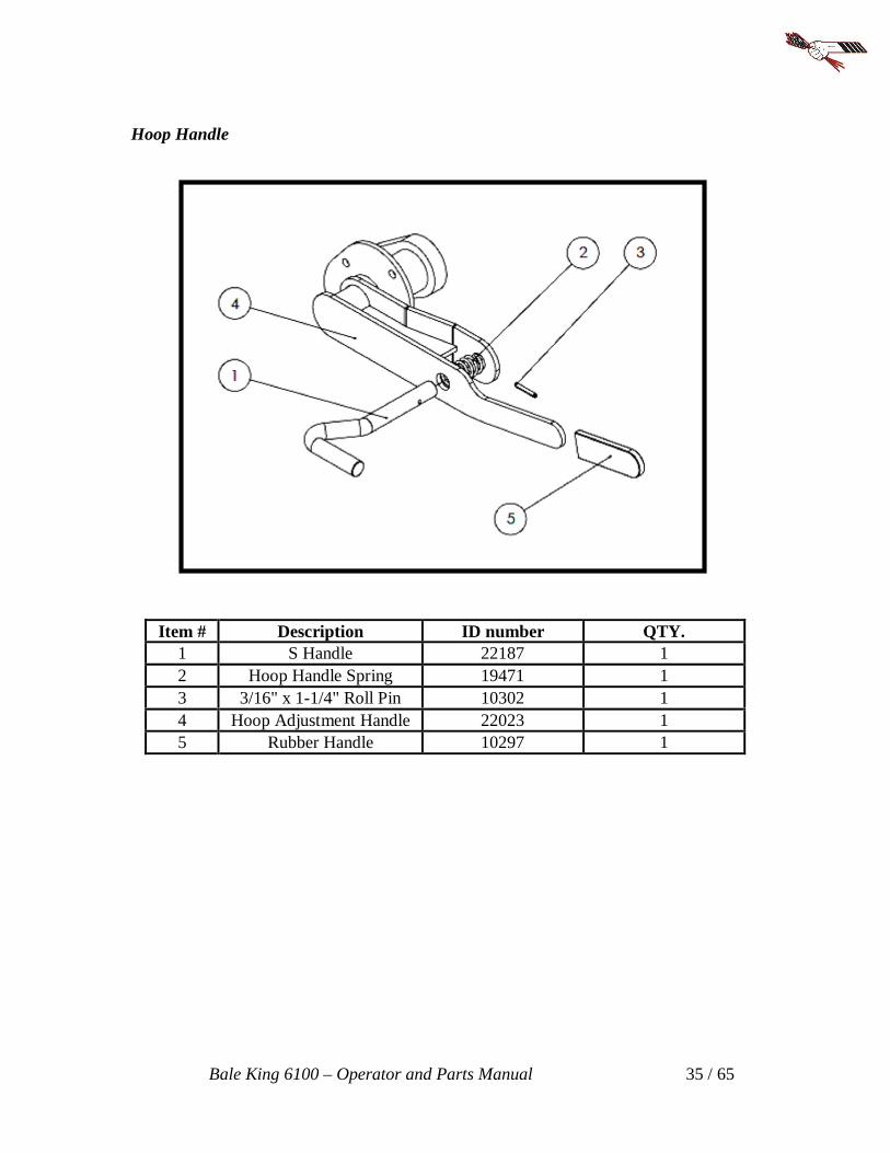
Hoop Handle
Item # Description ID number QTY. 1 S Handle 22187 1 2 Hoop Handle Spring 19471 1 3 3/16" x 1-1/4" Roll Pin 10302 1 4 Hoop Adjustment Handle 22023 1 5 Rubber Handle 10297 1
Bale King 6100 – Operator and Parts Manual 36 / 65
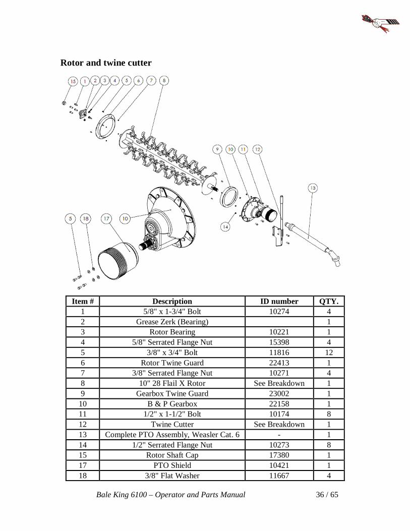
Rotor and twine cutter
Item # Description ID number QTY. 1 5/8" x 1-3/4" Bolt 10274 4 2 Grease Zerk (Bearing) 1 3 Rotor Bearing 10221 1 4 5/8" Serrated Flange Nut 15398 4 5 3/8" x 3/4" Bolt 11816 12 6 Rotor Twine Guard 22413 1 7 3/8" Serrated Flange Nut 10271 4 8 10" 28 Flail X Rotor See Breakdown 1 9 Gearbox Twine Guard 23002 1
10 B & P Gearbox 22158 1 11 1/2" x 1-1/2" Bolt 10174 8 12 Twine Cutter See Breakdown 1 13 Complete PTO Assembly, Weasler Cat. 6 - 1 14 1/2" Serrated Flange Nut 10273 8 15 Rotor Shaft Cap 17380 1 17 PTO Shield 10421 1 18 3/8" Flat Washer 11667 4
Bale King 6100 – Operator and Parts Manual 37 / 65
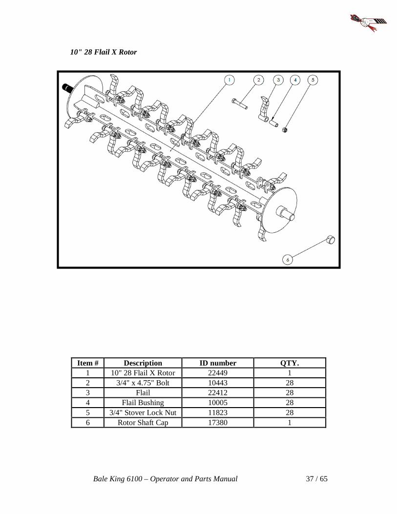
10" 28 Flail X Rotor
Item # Description ID number QTY. 1 10" 28 Flail X Rotor 22449 1 2 3/4" x 4.75" Bolt 10443 28 3 Flail 22412 28 4 Flail Bushing 10005 28 5 3/4" Stover Lock Nut 11823 28 6 Rotor Shaft Cap 17380 1

Bale King 6100 – Operator and Parts Manual 38 / 65
Gearbox Assembly

Bale King 6100 – Operator and Parts Manual 39 / 65
ITEM # DESCRIPTION ID NO QTY.
1 Housing 22158 1 2 End Cap 22158 1 3 Output Gear 22158 1 4 Input Gear 22158 1 5 Output Shaft 22158 1 6 Input Shaft 22158 1 7 Bearing(32009) 10497 2 8 Bearing(32012) 10496 2 9 Seal 45x60x8 24013 1
10 Seal 60x100x10 10498 1 11 3/8 NPT Pipe Plug 24014 2 12 3/8 NPT Relief Plug 24015 1 13 M8x25 Bolt Gr8.8 24026 6 14 M8 Lock Washer 24016 6 15 O-Ring 24017 1 16 O-Ring 24018 1 17 Shim 125x164x0.1 24022 2 18 Shim 125x164x0.3 24023 2 19 Name Plate(Bridgeview) --- --- 20 End Cap 22158 1 21 Seal 60x85x10 10500 1 22 Shim 68x74.5x0.1 24024 2 23 Shim 68x74.5x0.3 24025 2 24 1/4-28 UNF Grease Nipple 12080 1 25 M10x25 Bolt Gr8.8 15087 4 26 M10 Lock Washer 24021 4 27 Press Cup 24020 1

Bale King 6100 – Operator and Parts Manual 40 / 65
Twine cutter
Item # Description ID number QTY. 1 Rubber Handle 17587 1 2 Twine Cutter Handle 20862 1 3 1/4" Flat Washer 11666 2 4 1/4" x 3/4" Bolt 11809 4 5 1/4" Serrated Flange Nut 11812 4 6 Twine Cutter Holder Inside 176901 1 7 Twine Cutter Blade 17438 1 8 Twine Cutter Holder Outside 176911 1

Bale King 6100 – Operator and Parts Manual 41 / 65
Complete PTO Assembly, Weasler Cat. 6
Item # Description ID number QTY. 1 Safety Slide Lock Repair Kit 17567 1 2 WWCV Auto-Lock Yoke ASM 1-3/8"-21 Spline 20549 1 3 CV Cross and Bearing Kit 20550 2 4 CV Center Housing 20551 1 5 Yoke and Shaft Assembly Tractor Side 20552 1 6 Guard Repair Kit Tractor Side 20553 1 7 Outer Guard Assembly Tractor Side (Incl. item #6 ) 17583 1 8 Inner Guard Assembly Implement. Side (Incl. item # 9) 17585 1 9 Guard Repair Kit Implement Side 17272 1
10 Yoke and tube Assembly Implement Side 17584 1 11 Cross and Bearing Kit 17573 1 12 Shear Assembly 17581 1 13 Shear Bolt, 3/8" x 2" NC Grade 5 11817 1 14 5/8" x 3-1/2" NF Grade 8 Bolt 2 15 5/8" NF Lock Nut 2 16 WWCV Auto-Lock Assembly 1-3/4" - Spline 20556 1
Note: CV U-joint cross has equal length arms (4.19"). Bearing cup diameter (1.38").

Bale King 6100 – Operator and Parts Manual 42 / 65
PTO holder and manual
Item # Description ID number QTY. 1 1/2" Serrated Flange Nut 10273 1 2 1/2" Flat Washer 11668 1 3 Manual Cover Mount 22439 1 4 1/2" x 1-1/4" Bolt 10240 1 5 Operator Manual Cover 22409 1 6 1/4" x 3/4" Bolt 11809 4 7 3/8" Serrated Flange Nut 10271 8 8 PTO holder long channel 22836 1 9 3/8" x 3/4" Bolt 11816 7 10 5/16" x 3" Bolt 22844 1 11 Hose Clamp Top 1/2" Hose 21725 1 12 Hose Clamp Top 1/4" Hose 22182 1 13 Hydraulic Hose Clamp 1/2" 21561 6 14 Hydraulic Hose Clamp 1/4" 22181 2 15 5/16" x 3/4" Bolt 20903 4 16 5/16" Serrated Flange Nut. 11814 4 17 3/8" Nylon Lock Nut 10806 1 18 Front Plate 22838 1 19 PTO Transport Lock 22450 1 20 3/8" x 1" Bolt 13806 1 21 1/4" Serrated Flange Nut 11812 4 22 5/16"x3 1/2" Bolt 13765 1

Bale King 6100 – Operator and Parts Manual 43 / 65
Hitch
Item # Description ID number QTY. 1 3/4" Stover Lock Nut 11823 19 2 3/4" x 2.0" Bolt 13800 18 3 Hitch 23404 1 4 1.0" x 6.25" Bolt 23326 3 5 1" Stover Lock Nut 21746 3 6 7000 LBS Jack 23677 1 7 3/4" x 6" Bolt GR.8 23170 1 8 Casting Hitch (7500 LBS) 23404 1 9 Hitch Clevis 22441 1 11 21000 LBS Safety Chain 23559 1
Bale King 6100 – Operator and Parts Manual 44 / 65
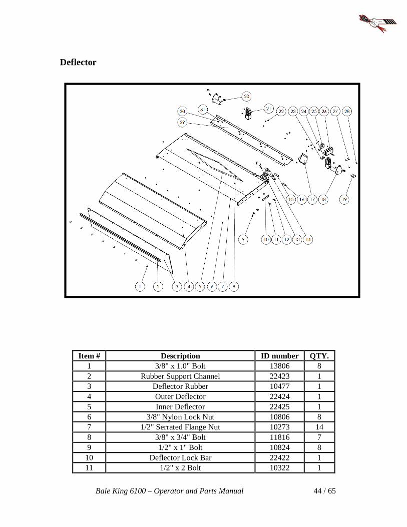
Deflector
Item # Description ID number QTY. 1 3/8" x 1.0" Bolt 13806 8 2 Rubber Support Channel 22423 1 3 Deflector Rubber 10477 1 4 Outer Deflector 22424 1 5 Inner Deflector 22425 1 6 3/8" Nylon Lock Nut 10806 8 7 1/2" Serrated Flange Nut 10273 14 8 3/8" x 3/4" Bolt 11816 7 9 1/2" x 1" Bolt 10824 8
10 Deflector Lock Bar 22422 1 11 1/2" x 2 Bolt 10322 1

Bale King 6100 – Operator and Parts Manual 45 / 65
12 1/2" x 2-1/2" Threaded Pin 13231 2 13 Cotter Pin (3/16" x 1-1/4") 11669 4 14 Hydraulic Cylinder (1.5 x 6 x 1) 21711 1 15 Cylinder Pin: 3/4" x 3-3/4" (3" Usable) 22008 1 16 Cylinder Pin: 3/4" x 3-1/2" (2-3/4" Usable) 22001 1 17 Deflector Fill Plate 22945 1 18 Deflector Pivot 22426 2 19 5/16" x 3.0" Socket Head Bolt 11783 4 20 Push-in Grommets 5/16" ID 21428 4 21 Electrical Diverter Valve 11743 2 22 3/8" x 3/4" Carriage Bolt 14072 6 23 5/16" Serrated Flange Nut 11814 8 24 5/16" Flat Washer 12496 4 25 Pilot Operated Check Valve 19114 1 26 Junction Box 13668 1 27 5/16" x 1.0" Bolt 20906 2 28 5/16" x 1-3/4" Bolt 21726 2 29 Hose Cover Panel 22436 1 30 3/8" Flat Washer 11667 10 31 3/8" Serrated Flange Nut 10271 9

Bale King 6100 – Operator and Parts Manual 46 / 65
Axles
Item # Description ID number QTY. 1 Torflex axles 22850 1 2 Inner Bearing 23567 2 3 Outer Bearing 23568 2 4 Inner Cup 23571 2 5 Outer Cup 23570 2 6 Seal 23569 2 7 Tire 14L-16.1SL (12 Ply) 22851 2 8 Rims W11C x 16.1 x 8 23742 2 9 Hubs 8 on 8 23572 2
10 Washer For Spindle 23564 2 11 Castle Nut 23566 2 12 Cotter Pin 23565 2 13 Dust Cap 23563 2 14 Twine Guard 23744 2 15 Grease Zerk (Hubs) 10270 2 16 Wheel Nut 23183 16 17 Wheel Stud 23572 16 18 1/2" x 1-1/4" Bolt 10240 8 19 1/2" Serrated Flange Nut 10273 8 20 3/4" Flat Washer 13317 4 21 3/4" Stover Lock Nut 11823 4 22 3/2" x 2.0" Bolt 13800 4

Bale King 6100 – Operator and Parts Manual 47 / 65
Hoist
Item # Description ID number QTY. 1 1/4" x 2-1/4" Roll Pin 23544 4 2 Top Pin (20-7/8") 23418 1 3 Bottom Pin (27-5/8") 23419 1 4 5/16" x 1-3/4" Bolt 21726 4 5 Wire Clamp 13629 1 6 Hose Clamp Top Mount 21725 4 7 Hydraulic Hose Clamp 1/2" 21561 8 8 Cylinder Pin (15-11/16") 23417 1 9 Linkage Pin (22-7/8") 23416 1
10 Hydraulic cylinder (4 x 14 x 2) 23094 1 11 Bottom Linkage 23743 1 12 Grease Zerk 16364 8 13 Top Linkage 23741 1 14 Grease Zerk (90o Degrees) 16389 1

Bale King 6100 – Operator and Parts Manual 48 / 65
Main deck

Bale King 6100 – Operator and Parts Manual 49 / 65
Item # Description ID number QTY 1 Idler Wheel Assembly See Breakdown 2 2 Light Assembly See Breakdown -- 3 Chain Motor Assembly See Breakdown -- 4 3/8" x 3-1/4" Bolt 23325 2 5 Pivot Pins 23594 2 6 3/8" Nylon Lock Nut 10806 2 7 Grease Zerk 16364 2
2082 Chain With Tab 23693 2 8 2082 Connector 23093 2
9 Main Deck 23748 1
Idler Wheel Assembly
Item # Description ID number QTY. 1 Snap ring Idler Wheel 23755 1 2 Idler Bushing 23756 2 3 Idler Wheel Bearing 23757 2 4 Idler Wheel 23758 1 5 Grease Zerk 16364 1 6 5/8" x 4-1/2" Grease 23597 1 7 Idler Wheel Clevis 23745 1 8 5/8" Heavy Flat Washer 17972 2 9 5/8" Lock Washer 13792 1
10 5/8" Nut 10176 2

Bale King 6100 – Operator and Parts Manual 50 / 65
Light assembly
Item # Description ID number QTY.
1 1/4" x 1.0" Bolt 11810 8 2 Right Light 22969 1 3 1/2" x 7-1/2" Bolt 13640 2 4 Right Light Bracket 23746 1 5 1/2" Flat Washer 11668 4 6 Compression Spring 20973 2 7 1/2" Nylon Lock Nut 10241 2 8 5/16" x 1.0" Bolt 20906 2 9 Junction Box 13668 1
10 5/16" Serrated Flange Nut 11815 2 11 Plastic SMV Sign kit 22411 1 12 Left Light 22968 1 13 Left Light Bracket 23749 1 14 1/4" Serrated Flange Nut 11812 8

Bale King 6100 – Operator and Parts Manual 51 / 65
Chain Motor Assembly
Item # Description ID number QTY. 1 1/4" Serrated Flange Nut 11812 2 2 Flow Divider (2082 Chain) 11742 1 3 1/4" Flat Washer 11666 2 4 1/4" x 2-3/4" Bolt 11811 2 5 5/8" Lock Washer 13792 2 6 5/8" x 1-3/4" Bolt NF Grade 8 10274 2 7 5/8" Flat Washer 13975 2 8 8 Tooth Sprocket 23747 2 9 1/2" x 4.0" Bolt 23540 8
10 Hydraulic Motor 22586 2 11 1/2" Nylon Lock Nut 10241 8 12 5/16" x 1-3/4" Bolt 21726 2 13 Hose Clamp Top 1/2" 21725 2 14 Hydraulic Hose Clamp 1/2" 21561 4

Bale King 6100 – Operator and Parts Manual 52 / 65
Loading fork
Item # Description ID number QTY. 1 Back Fork 23697 1 2 Grease Zerk 16364 2 3 Hydraulic Cylinder (3 x 18 x 1.5) 21717 2 4 Hydraulic Hose Clamp 1/2" 21561 14 5 Hose Clamp Top 1/2" 21725 7 6 5/16" x 1-3/4" Bolt 21726 7 7 3/8" x 2-3/4" Bolt 20908 2 8 Fork Pivot Pin 22006 2 9 3/8" Nylon Lock Nut 10806 2
10 Cotter Pin 93/16" x 1-1/2") 10072 8 11 Spring Bushing ( 1" Pin) 23708 4 12 Cylinder Pin (1" x 4-1/16") 22190 2 13 Wiring Clamp 13629 4 14 Cylinder Pin (1" x 3-1/2") 22291 2

Bale King 6100 – Operator and Parts Manual 53 / 65
Fine chop
Item # Description ID number QTY. 1 3/8" x 1" Bolt 13806 10 2 Fine Chop Mount (Rear) 22444 1 3 3/8" Serrated Flange Nut 10271 10 4 Fine Chop Bar 22442 1 5 1/4" x 3/4" Bolt 11809 26 6 1/2" Nylon Lock Nut 10241 1 7 1/2" Flat Washer 11668 1 8 Fine Chop Handle Spring 21713 1 9 1/2" x 2-1/2" Bolt 10804 1
10 Fine Chop Handle 22446 1 11 Rubber Handle 10297 1 12 Fine Chop Blade 10404 13 13 1/4" Serrated Flange Nut 11812 26 14 Fine Chop Handle Mount 22445 1 15 Fine Chop Mount (Front) 22443 1 16 Fine Chop Slot Cover 22438 1

Bale King 6100 – Operator and Parts Manual 54 / 65
Decal

Bale King 6100 – Operator and Parts Manual 55 / 65
Item # Description ID number QTY. 1 PTO Caution 12219 2 2 Stand Clear of Lift 12229 2 3 Side Discharge 12230 4 4 PIMA/AMC 12239 1 5 Red Reflective 13324 3 6 Amber Reflective 13325 3 7 Bale King 6100 22843 2 8 Hoop Adjustment 22165 1 9 Deflector Lock 22292 1
7
8 9

Bale King 6100 – Operator and Parts Manual 56 / 65
Hydraulics & Wiring Diagram

Bale King 6100 – Operator and Parts Manual 57 / 65
Chain Motor

Bale King 6100 – Operator and Parts Manual 58 / 65
Tilt/Fork/Deflector

Bale King 6100 – Operator and Parts Manual 59 / 65
Light Diagram

Bale King 6100 – Operator and Parts Manual 60 / 65
Diverter Diagram
Machine side

Bale King 6100 – Operator and Parts Manual 61 / 65
Tractor Side (Control Box #23988

Notes ______________________________________________________________________
______________________________________________________________________
______________________________________________________________________
______________________________________________________________________
______________________________________________________________________
______________________________________________________________________
______________________________________________________________________
______________________________________________________________________
______________________________________________________________________
______________________________________________________________________
______________________________________________________________________
______________________________________________________________________
______________________________________________________________________
______________________________________________________________________
______________________________________________________________________
______________________________________________________________________
______________________________________________________________________
______________________________________________________________________
______________________________________________________________________
______________________________________________________________________
______________________________________________________________________
______________________________________________________________________
______________________________________________________________________

BRIDGEVIEW MANUFACTURING INC. P.O. BOX 4, HWY 22
GERALD, SASK. S0A 1B0 CANADA
Ph: 306-745-2711 Fax: 306-745-336
Email: [email protected] www.bridgeviewmanufacturing.com